WO2016125842A1 - 心拍信号検出装置、およびそれに用いる気道内気体流量測定装置 - Google Patents
心拍信号検出装置、およびそれに用いる気道内気体流量測定装置 Download PDFInfo
- Publication number
- WO2016125842A1 WO2016125842A1 PCT/JP2016/053293 JP2016053293W WO2016125842A1 WO 2016125842 A1 WO2016125842 A1 WO 2016125842A1 JP 2016053293 W JP2016053293 W JP 2016053293W WO 2016125842 A1 WO2016125842 A1 WO 2016125842A1
- Authority
- WO
- WIPO (PCT)
- Prior art keywords
- gas flow
- flow rate
- sensor
- circuit
- airflow
- Prior art date
- Legal status (The legal status is an assumption and is not a legal conclusion. Google has not performed a legal analysis and makes no representation as to the accuracy of the status listed.)
- Ceased
Links
Images


Classifications
-
- A—HUMAN NECESSITIES
- A61—MEDICAL OR VETERINARY SCIENCE; HYGIENE
- A61B—DIAGNOSIS; SURGERY; IDENTIFICATION
- A61B1/00—Instruments for performing medical examinations of the interior of cavities or tubes of the body by visual or photographical inspection, e.g. endoscopes; Illuminating arrangements therefor
- A61B1/273—Instruments for performing medical examinations of the interior of cavities or tubes of the body by visual or photographical inspection, e.g. endoscopes; Illuminating arrangements therefor for the upper alimentary canal, e.g. oesophagoscopes, gastroscopes
-
- A—HUMAN NECESSITIES
- A61—MEDICAL OR VETERINARY SCIENCE; HYGIENE
- A61B—DIAGNOSIS; SURGERY; IDENTIFICATION
- A61B5/00—Measuring for diagnostic purposes; Identification of persons
- A61B5/72—Signal processing specially adapted for physiological signals or for diagnostic purposes
- A61B5/7271—Specific aspects of physiological measurement analysis
- A61B5/7278—Artificial waveform generation or derivation, e.g. synthesizing signals from measured signals
-
- A—HUMAN NECESSITIES
- A61—MEDICAL OR VETERINARY SCIENCE; HYGIENE
- A61B—DIAGNOSIS; SURGERY; IDENTIFICATION
- A61B1/00—Instruments for performing medical examinations of the interior of cavities or tubes of the body by visual or photographical inspection, e.g. endoscopes; Illuminating arrangements therefor
- A61B1/267—Instruments for performing medical examinations of the interior of cavities or tubes of the body by visual or photographical inspection, e.g. endoscopes; Illuminating arrangements therefor for the respiratory tract, e.g. laryngoscopes, bronchoscopes
- A61B1/2676—Bronchoscopes
-
- A—HUMAN NECESSITIES
- A61—MEDICAL OR VETERINARY SCIENCE; HYGIENE
- A61B—DIAGNOSIS; SURGERY; IDENTIFICATION
- A61B5/00—Measuring for diagnostic purposes; Identification of persons
- A61B5/02—Detecting, measuring or recording for evaluating the cardiovascular system, e.g. pulse, heart rate, blood pressure or blood flow
- A61B5/024—Measuring pulse rate or heart rate
- A61B5/0245—Measuring pulse rate or heart rate by using sensing means generating electric signals, i.e. ECG signals
-
- A—HUMAN NECESSITIES
- A61—MEDICAL OR VETERINARY SCIENCE; HYGIENE
- A61B—DIAGNOSIS; SURGERY; IDENTIFICATION
- A61B5/00—Measuring for diagnostic purposes; Identification of persons
- A61B5/08—Measuring devices for evaluating the respiratory organs
- A61B5/087—Measuring breath flow
-
- A—HUMAN NECESSITIES
- A61—MEDICAL OR VETERINARY SCIENCE; HYGIENE
- A61B—DIAGNOSIS; SURGERY; IDENTIFICATION
- A61B5/00—Measuring for diagnostic purposes; Identification of persons
- A61B5/68—Arrangements of detecting, measuring or recording means, e.g. sensors, in relation to patient
- A61B5/6801—Arrangements of detecting, measuring or recording means, e.g. sensors, in relation to patient specially adapted to be attached to or worn on the body surface
- A61B5/6802—Sensor mounted on worn items
- A61B5/6803—Head-worn items, e.g. helmets, masks, headphones or goggles
-
- A—HUMAN NECESSITIES
- A61—MEDICAL OR VETERINARY SCIENCE; HYGIENE
- A61B—DIAGNOSIS; SURGERY; IDENTIFICATION
- A61B5/00—Measuring for diagnostic purposes; Identification of persons
- A61B5/68—Arrangements of detecting, measuring or recording means, e.g. sensors, in relation to patient
- A61B5/6846—Arrangements of detecting, measuring or recording means, e.g. sensors, in relation to patient specially adapted to be brought in contact with an internal body part, i.e. invasive
- A61B5/6847—Arrangements of detecting, measuring or recording means, e.g. sensors, in relation to patient specially adapted to be brought in contact with an internal body part, i.e. invasive mounted on an invasive device
- A61B5/6852—Catheters
-
- A—HUMAN NECESSITIES
- A61—MEDICAL OR VETERINARY SCIENCE; HYGIENE
- A61B—DIAGNOSIS; SURGERY; IDENTIFICATION
- A61B5/00—Measuring for diagnostic purposes; Identification of persons
- A61B5/72—Signal processing specially adapted for physiological signals or for diagnostic purposes
- A61B5/7235—Details of waveform analysis
- A61B5/7253—Details of waveform analysis characterised by using transforms
- A61B5/7257—Details of waveform analysis characterised by using transforms using Fourier transforms
-
- G—PHYSICS
- G01—MEASURING; TESTING
- G01F—MEASURING VOLUME, VOLUME FLOW, MASS FLOW OR LIQUID LEVEL; METERING BY VOLUME
- G01F1/00—Measuring the volume flow or mass flow of fluid or fluent solid material wherein the fluid passes through a meter in a continuous flow
- G01F1/68—Measuring the volume flow or mass flow of fluid or fluent solid material wherein the fluid passes through a meter in a continuous flow by using thermal effects
- G01F1/684—Structural arrangements; Mounting of elements, e.g. in relation to fluid flow
- G01F1/688—Structural arrangements; Mounting of elements, e.g. in relation to fluid flow using a particular type of heating, cooling or sensing element
- G01F1/69—Structural arrangements; Mounting of elements, e.g. in relation to fluid flow using a particular type of heating, cooling or sensing element of resistive type
Definitions
- the present invention can easily detect a heartbeat signal that reflects the cardiac activation of a living body without using an electrode attached to the living body, and more preferably can evaluate the physiological function of the heart.
- the present invention relates to a heartbeat signal detection device.
- the biological heartbeat signal is important biological information.
- an electrocardiographic induction device that detects an electrocardiogram obtained through a plurality of ECG electrodes attached to a living body as a heartbeat signal has been used.
- the apparatus described in Patent Document 1 and Patent Document 2 is the same.
- This electrocardiogram is also referred to as an electrocardiogram-induced waveform or ECG waveform, and the R-wave contained therein is easy to detect because it has the characteristic of having a very clear pulse shape.
- ECG waveform electrocardiogram-induced waveform
- the R-wave contained therein is easy to detect because it has the characteristic of having a very clear pulse shape.
- the present invention has been made in the background of the above circumstances, and the object of the present invention is to provide a cardiac action of a living body, preferably a stroke volume, without using an ECG electrode attached to the living body. Another object of the present invention is to provide a heartbeat signal detecting device that can easily detect a heartbeat signal that reflects the above.
- a respiratory waveform of the lung that is, a ventilation waveform, showing a temporal change in the amount of inhaled air and the amount of exhaled air exhausted from the lung of the living body.
- a pulsation component that pulsates in synchronization with the heartbeat is superimposed on the ventilation waveform of the lung, and that the pulsation component corresponds to a volume change of the lung heart.
- the lungs and heart are housed in the thoracic cavity isolated by the relatively rigid rib cage surrounded by the ribs, sternum, and thoracic vertebra and the diaphragm that closes the lower opening of the rib cage.
- the volume change is smaller than the lung volume change due to breathing exercise, it is clearly superimposed on the lung ventilation waveform because of the short exercise cycle, so the ventilation waveform, which is the gas flow rate in the airway including the mouth and nasal cavity of the living body, is It has been found that if detected, a heartbeat signal is extracted therefrom.
- the present invention has been made based on such knowledge.
- the gist of the present invention is (a) a heartbeat signal detection device for detecting a heartbeat signal of a living body, (b) an airflow sensor for detecting the flow of exhalation and inspiration of the living body, c) a gas flow calculation control unit that outputs a respiration signal that reflects the respiration movement of the living body based on an output signal from the air flow sensor; and (d) a respiration from the respiration signal output from the gas flow calculation control unit. And a waveform analysis control unit that extracts a frequency component synchronized with the beat of the heart of the living body superimposed on the signal and outputs a heartbeat signal representing the beat.
- the waveform analysis control unit extracts a frequency component synchronized with the heartbeat of the living body superimposed on the breathing signal from the breathing signal output from the gas flow calculation control unit, and the beat A heartbeat signal representing is output. For this reason, by using the heartbeat signal, it is possible to easily detect a heartbeat signal representing the heartbeat of the living body without using an ECG electrode attached to the living body. That is, even an infant whose skin is weak and it is difficult to apply the ECG electrode to the skin for a long time for electrocardiographic measurement can easily obtain a heartbeat signal.
- heart rate signals reflecting actual volume changes of the heart that is, cardiac output
- cardiac output the presence or absence of heart pulsation can be confirmed with higher reliability compared to the conventional method using an electrocardiogram-induced waveform.
- the airflow sensor may be attached to any part such as a nostril or in vitro as long as it is a part that can detect the exhalation and inhalation gas flow of the living body. Absent.
- the endotracheal intubation tube or a connection tube that connects the endotracheal intubation tube and the ventilator is provided outside the living body.
- the airflow sensor is used in the mask or nasal cannula or in the mask or nasal cannula and a ventilator. It is provided in the connecting pipe between.
- the airflow sensor comprises a circuit base film formed on the inner surface with a heater element composed of an electric resistance element whose electric resistance changes according to temperature, such as a platinum resistance element or a gold resistance element.
- the electric resistance of the heater which is mounted along the inner wall surface of the pipe through which the gas flows and with a predetermined gap with respect to the inner wall face and is energized and heated, changes according to the flow velocity of the gas flowing through the pipe. Based on the above, the gas flow rate in the pipe is detected.
- a space is formed between the heater and the pipe for thermal insulation transmitted from the heater in the pipe direction.
- the heater is attached to the inner wall of the tube along the inner wall of the tube and with a predetermined gap from the inner wall surface. Therefore, in order to detect the gas flow rate with a line instead of a point, the flow rate can be measured even with a winding pipe, and a space for thermal insulation is formed between the heater and the pipe. Responsiveness to heat is determined by the heat capacity, and as a result, a high-speed response of 100 milliseconds or less can be realized.
- the gas flow rate measurement circuit having a bridge circuit (electric bridge) including the heater element as one or two of the four resistance elements, and the output of the gas flow rate measurement circuit reflecting the resistance value of the heater element.
- a gas flow calculation control unit that calculates a gas flow rate or a gas flow rate based on an output signal of the gas flow rate measurement circuit from a previously stored relationship between the signal and the gas flow rate or gas flow rate.
- the waveform analysis control unit is configured such that the respiratory motion output from the gas flow calculation control unit, that is, a respiratory signal reflecting the entire lung volume, is superimposed on the respiratory signal.
- the frequency component of the pulmonary volume component pulsating from the above is removed, and a ventilation component signal representing the lung volume component derived from the thorax and diaphragm of the living body is output.
- the respiratory signal and the heartbeat signal can be obtained simultaneously, it is possible to monitor the respiratory heartbeat reflecting the cardiac function with a single device, and in emergency lifesaving with time, place, and human constraints. There is an advantage that medical work can be performed in a short time.
- a heartbeat signal evaluation control unit for evaluating a functional abnormality or anatomical abnormality of the two chambers and two chambers constituting the heart based on the heartbeat signal analyzed by the waveform analysis control unit.
- the heartbeat signal evaluation control unit calculates a correlation coefficient between the heartbeat signal analyzed by the waveform analysis control unit and the abnormality evaluation pattern stored in advance, and the correlation coefficient exceeds a preset determination value. Based on this, abnormal function or anatomical abnormality of the two chambers and two chambers constituting the heart is evaluated. In this way, not only a heartbeat signal can be obtained, but also the functional abnormality or anatomical abnormality of the two chambers and two chambers constituting the heart can be known based on the heartbeat signal.
- an airflow gas flow rate measuring device for measuring the gas flow rate in the airway at the distal end portion of the flexible sheath including the airflow sensor,
- the flexible A cylindrical first sensor substrate provided integrally or separately at the distal end of the airflow measurement catheter passed through the sheath; and (c) wound in a cylindrical shape on the outer peripheral surface of the first sensor substrate.
- a flexible first circuit base film fixed in a state; and (d) one or two first heater elements formed on an outer peripheral surface of the first circuit base film;
- the gas flow rate measuring device Projecting from the tip of the fluid measurement catheter Is a enlarged basket diameter by is to contain.
- the outer peripheral surface of the flexible first circuit substrate film fixed in a cylindrically wound state on the outer peripheral surface of the first sensor substrate. Since the first heater element is formed and the diameter-expanding basket whose diameter is expanded by the operation wire passing through the fluid measurement catheter being pushed out, the first air flow sensor is positioned at the center in the airway.
- the flow resistance in the airway is small compared to the conventional type in which the measurement gas is passed between the vent hole formed in the side surface of the cylindrical sensor substrate fixed to the catheter and the opening at the other end.
- the structure is such that mucus stays and is not clogged in the airway, the gas flow rate can be measured accurately and easily.
- an airflow gas flow rate measuring device for measuring the gas flow rate in the airway at the distal end portion of the flexible sheath including the airflow sensor, (b) for the fluid measurement An operation wire provided through the catheter, and (c) a plurality of elastic wires in which the distal end portion and the rear end portion are bundled together, provided at the distal end portion of the operation wire, and the distal end of the catheter for fluid measurement
- a diameter-enlarging basket that expands by being protruded from, (d) a columnar or cylindrical second sensor substrate provided at the tip of the diameter-enlarged basket, and (e) the second sensor substrate.
- the air flow sensor having a heater element
- the door is to contain. According to the gas flow measuring apparatus in the airway configured as described above, the outer peripheral surface of the flexible second circuit substrate film fixed in a cylindrically wound state on the outer peripheral surface of the second sensor substrate.
- the second heater element is formed and the diameter-expanding basket whose diameter is expanded by the operation wire passing through the fluid measurement catheter being pushed out
- the second air flow sensor is positioned at the center in the airway, so that one end The flow resistance in the airway is small compared to the conventional type in which the measurement gas is passed between the vent hole formed in the side surface of the cylindrical sensor substrate fixed to the catheter and the opening at the other end.
- the structure is such that mucus retention and clogging in the bronchi are unlikely to occur, the gas flow rate can be measured accurately and easily.
- an airflow gas flow rate measuring device for measuring the gas flow rate in the airway at the distal end portion of the flexible sheath including the airflow sensor, (b) for the airflow measurement
- a cylindrical first sensor base provided integrally or separately on the distal end of the catheter; and (c) flexibility fixed in a state of being wound in a cylindrical shape on the outer peripheral surface of the first sensor base.
- a first air flow sensor having (d) one or two first heater elements formed on the outer peripheral surface of the first circuit base film, and through the fluid measuring catheter.
- the operation wire provided and (e) a plurality of elastic wires in which the distal end portion and the rear end portion are bundled with each other, are provided at the distal end portion of the operation wire, and are projected from the distal end of the fluid measuring catheter.
- Expanded bus that expands diameter (F) a columnar or cylindrical second sensor substrate provided at the tip of the diameter-enlarged basket; and (g) a cylindrical shape wound on the outer peripheral surface of the second sensor substrate.
- a second airflow sensor comprising: a flexible second circuit base film fixed in a state; and (h) one or two second heater elements formed on an outer peripheral surface of the second circuit base film. Is to include.
- the first heater element is formed, and the second heater element is formed on the outer peripheral surface of the flexible second circuit substrate film fixed in a cylindrically wound state on the outer peripheral surface of the second sensor substrate.
- the diameter-enlarging basket that expands when the operation wire passing through the fluid-measuring catheter is pushed out and positions the first air flow sensor and the second air flow sensor in the center of the airway.
- the flow resistance in the airway is reduced, and Less likely to cause mucus retention or clogging in the airways Because it is concrete, gas flow rate is accurately and easily measured.
- the heater element located on the upstream side of the gas in the airway of the first heater element and the second heater element.
- the flexible first circuit substrate film is fixed in a state of being wound in a cylindrical shape on an outer peripheral surface of the first sensor substrate via a spacer.
- a gap is formed between at least a portion of the circuit substrate film where the first heater element is formed and the outer peripheral surface of the first sensor substrate.
- the flexible second circuit substrate film is fixed in a state of being wound in a cylindrical shape on the outer peripheral surface of the second sensor substrate via a spacer, whereby the second circuit substrate film is flexible.
- a gap is formed between at least a portion of the circuit substrate film where the second heater element is formed and the outer peripheral surface of the second sensor substrate.
- a pair of the first heater elements is formed on the first circuit base film.
- a first gas flow velocity measurement having a pair of bridge circuits each composed of four resistance elements each including the pair of first heater elements and a differential amplifier that outputs an output signal corresponding to an output signal difference between the pair of bridge circuits.
- a circuit and a first gas flow rate calculation control unit that calculates a first gas flow rate signal representing a gas flow rate in the airway based on an output signal from a previously stored relationship are included.
- This first gas flow signal represents the direction of gas flow in one breath with one peak and valley regardless of the direction of gas flow in the airway within one breathing cycle. Information indicating the direction is obtained. Further, the gas flow rate can be calculated from the output of the bridge circuit having the heater element on the upstream side of the flow.
- a pair of the second heater elements is formed on the second circuit base film.
- a second gas flow velocity measurement having a pair of bridge circuits each composed of four resistance elements each including the pair of second heater elements and a differential amplifier that outputs an output signal corresponding to an output signal difference between the pair of bridge circuits.
- a circuit and a second gas flow rate calculation control unit that calculates a second gas flow rate signal representing the gas flow rate in the airway based on the output signal from a previously stored relationship are included.
- This second gas flow rate signal represents the direction of gas flow in one breath with one mountain and valley regardless of the direction of gas flow in the airway within one breathing cycle. Direction information is obtained. Further, the gas flow rate can be calculated from the output of the bridge circuit having the heater element on the upstream side of the flow.
- an airflow gas flow measuring device for measuring the gas flow rate in the airway at the distal end portion of the flexible sheath including the airflow sensor,
- the flexible sheath A cylindrical first sensor substrate provided integrally or separately on the distal end of the airflow measurement catheter passed through the device, and
- an operation wire inserted and removed from the distal end of the first sensor substrate;
- the distal end portion and the rear end portion are composed of a plurality of elastic wires bundled together, provided at the distal end portion of the operation wire, and expanded in diameter by being projected from the distal end of the fluid measuring catheter.
- the airflow sensor is located in the center of the expansion basket in the axial direction and in the center of the cross section, and the airflow sensor is located upstream of the expansion basket in the expiratory section, the gas flow rate in the expiratory section is more accurate. Is measured.
- an airway gas flow rate measuring device for measuring the gas flow rate in the airway at the distal end portion of the flexible sheath is not a respiratory flow in which a heartbeat signal of a living body is detected, for example, an airflow in a hollow organ of the living body or It can also be used for detection of fluid flow rate or flow velocity such as liquid flow.
- Such an aspect of the invention for other uses is configured as follows as a biological organ fluid flow rate measuring device.
- a biological organ fluid flow rate measuring device for measuring a fluid flow rate in a biological organ at a distal end portion of a flexible sheath, the (b) the flexible A cylindrical first sensor substrate provided integrally or separately at the distal end of the airflow measurement catheter passed through the sheath; and (c) wound in a cylindrical shape on the outer peripheral surface of the first sensor substrate.
- An air flow sensor having a flexible first circuit base film fixed in a state; and (d) one or two first heater elements formed on the outer peripheral surface of the first circuit base film; e) an operation wire provided through the fluid measuring catheter; and (f) a plurality of elastic wires in which a front end portion and a rear end portion are bundled together, and provided at a front end portion of the operation wire, Protruding from the tip of the fluid measurement catheter And the diameter basket expanded in Rukoto is to contain.
- the outer peripheral surface of the flexible first circuit substrate film fixed in a state of being wound in a cylindrical shape on the outer peripheral surface of the first sensor substrate.
- the first heater element is formed on the diameter of the basket and the diameter-enlarged basket that is expanded by the operation wire passing through the fluid measurement catheter is pushed out, the first air flow sensor is positioned at the center of the airway.
- the measurement gas is passed between the vent hole formed in the side surface of the cylindrical sensor base material, one end of which is fixed to the catheter, and the other end, the inside of the hollow organ of the living body Since the flow resistance is reduced and the mucus stays and clogs in the hollow organ of the living body is difficult to occur, the gas flow rate can be measured accurately and easily.
- a biological organ fluid flow rate measuring device for measuring a fluid flow rate in a biological organ at a distal end portion of a flexible sheath, including the air flow sensor, wherein (b) And (c) an operation wire provided through the flexible sheath, and (c) a plurality of elastic wires in which a front end portion and a rear end portion are bundled with each other, and provided at the front end portion of the operation wire.
- a diameter-expanding basket that expands by protruding from the distal end of the measurement catheter; (d) a columnar or cylindrical second sensor substrate provided at the distal end of the diameter-expanding basket; A flexible second circuit substrate film fixed in a cylindrically wound state on the outer peripheral surface of the second sensor substrate; and (f) 1 formed on the outer peripheral surface of the second circuit substrate film.
- two second heater elements The sensor is to contain. According to the fluid flow measuring device in the living organ configured as described above, the outer peripheral surface of the flexible second circuit substrate film fixed in a cylindrically wound state on the outer peripheral surface of the second sensor substrate.
- the second heater element is formed on the inner diameter of the second airflow sensor, the diameter-enlarged basket that expands the diameter of the operation wire passing through the flexible sheath is positioned at the center of the airway.
- the measurement gas is passed between the vent hole formed in the side surface of the cylindrical sensor base material, one end of which is fixed to the catheter, and the other end, the inside of the hollow organ of the living body Since the flow resistance is reduced and the mucus stays and clogs in the hollow organ of the living body is difficult to occur, the gas flow rate can be measured accurately and easily.
- a biological organ fluid flow rate measuring device for measuring the gas flow rate in the airway at the distal end of the flexible sheath
- the flexible sheath is A cylindrical first sensor base provided integrally or separately at the tip, and (c) a flexible first fixed in a cylindrically wound state on the outer peripheral surface of the first sensor base.
- a first airflow sensor having one circuit base film, and (d) one or two first heater elements formed on the outer peripheral surface of the first circuit base film, and provided through the fluid measurement catheter.
- a plurality of elastic wires whose front end and rear end are bundled together, provided at the front end of the operation wire, and protruding from the front end of the fluid measuring catheter.
- a diameter-enlarging basket that expands in diameter (f) A columnar or cylindrical second sensor substrate provided at the tip of the diameter-enlarged basket; and (g) a flexible fixed in a state of being wound in a cylindrical shape on the outer peripheral surface of the second sensor substrate.
- a second airflow sensor having (h) one or two second heater elements formed on the outer peripheral surface of the second circuit substrate film.
- the diameter-enlarged basket that is formed and expands when the operation wire that passes through the flexible sheath is pushed out positions the first airflow sensor and the second airflow sensor in the center of the airway, so that one end is a catheter.
- the flow resistance in the hollow organ of the living body is reduced. Mucus retention and clogging in hollow organs of living bodies . Doing so may but is unlikely to occur structure, the fluid flow rate is accurately and easily measured.
- the first air heater element is located upstream of the gas in the airway of the first heater element and the second heater element.
- the flexible first circuit substrate film has an outer peripheral surface of the first sensor substrate via a spacer. Between the portion of the first circuit substrate film where at least the first heater element is formed and the outer peripheral surface of the first sensor substrate. A gap is formed in Thereby, since the heat insulation between the said 1st heater element formed in the 1st circuit base film and the said 1st sensor base material is improved, gas flow rate is measured more correctly. Moreover, since the heat responsiveness is determined by the heat capacity of the first heater element itself, a high-speed response can be obtained.
- the flexible second circuit base film is an outer peripheral surface of the second sensor base through a spacer. Between the portion of the second circuit substrate film where at least the second heater element is formed and the outer peripheral surface of the second sensor substrate. A gap is formed in Thereby, since the heat insulation between the said 2nd heater element formed in the 2nd circuit base film and the said 2nd sensor base material is improved, gas flow rate is measured more correctly. In addition, since the heat responsiveness is determined by the heat capacity of the second heater element itself, a high-speed response can be obtained.
- a pair of the first heater elements are formed on the first circuit base film.
- a first gas flow velocity measurement having a pair of bridge circuits each composed of four resistance elements each including the pair of first heater elements and a differential amplifier that outputs an output signal corresponding to an output signal difference between the pair of bridge circuits.
- a circuit and a first gas flow rate calculation control unit that calculates a first gas flow rate signal representing a gas flow rate in the airway based on an output signal from a previously stored relationship are included.
- This first gas flow signal represents the direction of gas flow in one breath with one peak and valley regardless of the direction of gas flow in the airway within one breathing cycle. Information indicating the direction is obtained. Further, the gas flow rate can be calculated from the output of the bridge circuit having the heater element on the upstream side of the flow.
- a pair of the second heater elements are formed on the second circuit base film.
- a second gas flow velocity measurement having a pair of bridge circuits each composed of four resistance elements each including the pair of second heater elements and a differential amplifier that outputs an output signal corresponding to an output signal difference between the pair of bridge circuits.
- a circuit and a second gas flow rate calculation control unit that calculates a second gas flow rate signal representing the gas flow rate in the airway based on the output signal from a previously stored relationship are included.
- This second gas flow rate signal represents the direction of gas flow in one breath with one mountain and valley regardless of the direction of gas flow in the airway within one breathing cycle. Direction information is obtained. Further, the gas flow rate can be calculated from the output of the bridge circuit having the heater element on the upstream side of the flow.
- an airflow gas flow rate measuring device for measuring the gas flow rate in the airway at the distal end portion of the flexible sheath, including (a) the airflow sensor, A cylindrical first sensor base provided integrally or separately at the tip of the airflow measurement catheter passed through the flexible sheath, and (c) an operation to be taken in and out from the tip of the first sensor base.
- the air flow sensor and a first heater element 1 or 2 which is formed on the outer peripheral surface of the first circuit substrate film comprises.
- the airflow sensor is located in the center of the expansion basket in the axial direction and in the center of the cross section, and the airflow sensor is located upstream of the expansion basket in the expiratory section, the gas flow rate in the expiratory section is more accurate. Is measured.
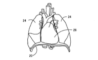
- FIG. 1 is a schematic diagram illustrating a living thorax.
- 2 is a schematic diagram illustrating the lung and heart housed in the rib cage of FIG. 1. It is a figure explaining the structure of the heart rate signal detection apparatus of one Example of this invention, and the principal part of the control function of the electronic control apparatus contained in it. It is a perspective view explaining the mechanical structure of the airflow sensor used for FIG. It is a perspective view which shows the example in which the airflow sensor of FIG. 4 was provided in the mask which covers the nose and mouth of a biological body. It is a circuit diagram explaining the structure of the gas flow electric circuit which drives the airflow sensor of FIG. It is a figure explaining the relationship calculated
- FIG. 6 is a perspective view showing an example of an airflow sensor according to another embodiment of the present invention, in which a pair of detection resistance elements for measuring a flow rate by changing a resistance value are provided on both sides of a heater element, corresponding to FIG. 4.
- FIG. 5 is a perspective view illustrating an example of an airflow sensor according to another embodiment of the present invention, in which a pair of heater elements and a pair of temperature compensation elements are provided, and corresponds to FIG. 4.
- FIG. 1 is a schematic diagram illustrating a lung and an airway of a living body. It is the schematic which shows the catheter protruded from the front-end
- FIG. 23 is a perspective view showing an operation in which the air flow sensor of FIG. 22 deploys the diameter-enlargement basket from the air-flow measurement catheter provided at the distal end portion, and (a) shows a state before the diameter-expansion basket is projected from the air-flow measurement catheter. (B) shows the state in the middle of projecting the enlarged basket from the catheter for airflow measurement, and (c) shows the state after projecting the enlarged basket from the catheter for airflow measurement.
- FIG. 26 is a VV sectional view of the airflow sensor of FIG. 25. It is a figure which expand
- FIG. 25 It is a figure which shows the responsiveness of the airflow sensor shown by FIG. 25 and FIG. It is a circuit diagram explaining the structure of the gas flow velocity measurement circuit containing the heater element of the airflow sensor of FIG. It is a figure which shows the gas flow rate in an airway calculated
- FIG. 25 is a perspective view illustrating a configuration of an airway gas flow rate measuring device when the airflow sensor of the embodiment of FIG. 33 is used, and corresponds to FIG. 24. It is a perspective view explaining the structure of the airflow sensor of the other Example of this invention, Comprising: It is a figure corresponded in FIG.
- the living body 10 is isolated by a relatively rigid rib cage 18 surrounded by the ribs 12, the sternum 14, and the thoracic vertebra 16 and a diaphragm 20 that closes the lower opening of the rib cage 18.
- the lung 24 and the heart 26 are accommodated in the thoracic cavity. Although the volume change of the heart 26 due to pulsation is smaller than the volume change of the lung 24 due to breathing exercise, the exercise cycle is short, so the ventilation waveform of the lung 24 is changed.
- a respiratory waveform that is a gas flow velocity or gas flow rate passing through the trachea 28 of the living body 10 is detected, a heartbeat signal is extracted therefrom. Details will be described below.
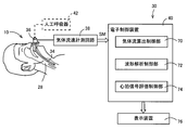
- FIG. 3 is a diagram for explaining the configuration of the heartbeat signal detection device 30 and the functions of the electronic control device 40 provided in the heartbeat signal detection device 30 according to an embodiment of the present invention.
- the heartbeat signal detection device 30 corresponds to an airflow sensor 36 attached to an endotracheal intubation tube 34 inserted into the trachea 28 of the living body 10 and a gas flow rate passing through the airflow sensor 36 based on a signal from the airflow sensor 36.
- a gas flow velocity measurement circuit 38 that outputs a measurement signal SM to be output, an electronic control device 40 that extracts a heartbeat signal SH representing a volume change of the heart 26 from the measurement signal SM output from the gas flow velocity measurement circuit 38, and an electronic control device And a display device 76 for displaying the heart rate, the waveform of the heartbeat signal SH, the respiratory waveform, the evaluation of the heartbeat waveform, and the like, which are the signal processing results of 40.
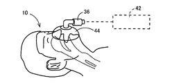
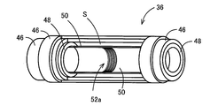
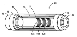
- FIG. 4 is a perspective view showing an example of the mechanical configuration of the airflow sensor 36.
- the airflow sensor 36 is attached to the base of the endotracheal intubation tube 34 in FIG. 3, but may be any device that detects the flow rate of gas passing through the trachea 28 of the living body 10.
- You may provide in the site
- 5 may be provided in a mask 44 covering the nose and mouth of the living body 10 shown in FIG. 5, a flexible tube connecting the mask 44 and the ventilator 42, or a connection adapter. 3 and 5, the ventilator 42 is connected as necessary, and is not necessarily provided.
- the airflow sensor 36 includes a two-layered tubular case 46 that can be connected to the endotracheal intubation tube 34 and the ventilator 42, and a center in the circular tubular case 46.
- a pair of tubular spacers 48 mounted at a predetermined interval in the axial direction and an inner wall surface of the case 46 having a central portion in the central axial direction by being fixed to the inner peripheral surface of the pair of tubular spacers 48
- a circuit substrate film 50 having electrical insulation and flexibility, such as parylene resin, epoxy resin, polyimide resin, and the like, which is attached (fixed) along the inner wall surface with a predetermined gap S therebetween,
- the circuit base film 50 is formed on the inner surface in the central axis direction by photolithography, and is composed of an electric resistance element such as a platinum resistance element or a gold resistance element whose electric resistance changes according to temperature.
- a gas flow rate in the circular tubular case 46 is determined based on the fact that the electric resistance of the heater elements 52a and 52b that are provided with a pair of heater elements 52a and 52b and that is heated by energization changes according to the gas flow rate flowing through the pipes. It is to detect.
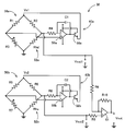
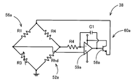
- FIG. 6 is a configuration example of the gas flow velocity measurement circuit 38 and shows a constant temperature type measurement circuit.
- the gas flow velocity measurement circuit 38 is composed of four resistors R1, R2, R3, and a heater element 52a (resistance value Rhd), and a first bridge circuit 56a to which a first bridge power supply voltage Vs1 is applied.
- a first measurement circuit 60a that amplifies the output voltage Vout1 of the first bridge circuit 56a by the first feedback amplifier 59a and causes a current corresponding to the signal to flow to the first bridge circuit 56a through the first transistor 58a.
- the gas flow rate measurement circuit 38 includes four resistors R5, R6, R7, and a heater element 52b (resistance value Rhu).
- the output voltage Vout2 of the two-bridge circuit 56b is amplified by the second feedback amplifier 59b, and a second measurement circuit 60b is provided that causes a current corresponding to the signal to flow to the second bridge circuit 56b through the second transistor 58b.
- the output voltage Vout1 and the output voltage Vout2 represent the air velocity.
- the gas flow velocity measuring circuit 38 further includes a differential amplifier 61 that amplifies the difference voltage between the output voltage Vout1 of the first bridge circuit 56a and the output voltage Vout2 of the second bridge circuit 56b and outputs the output voltage Vout.
- the resistor R3 is a variable resistor that adjusts the balanced state of the first bridge circuit 56a
- the resistor R7 is a variable resistor that adjusts the balanced state of the second bridge circuit 56b.
- the temperature of the first heater element 52a decreases and its resistance value Rhd decreases.
- the first bridge power supply voltage Vs1 is increased by the first feedback amplifier 59a so as to return the first bridge circuit 56a to the original equilibrium state, the temperature of the first heater element 52a is increased, and the first heater element 52a The temperature is maintained at a constant temperature.
- the temperature of the second heater element 52b decreases and its resistance value Rhu decreases, so that the second bridge circuit 56b is brought into the initial equilibrium state.
- the second bridge power supply voltage Vs2 is increased by the feedback amplifier 59b so that the temperature of the second heater element 52b is raised, and the temperature of the heater element 52b is maintained at a constant temperature.
- the output voltage Vout which is output from the differential amplifier 61 and represents the difference voltage between the output voltage Vout1 of the first bridge circuit 56a and the output voltage Vout2 of the second bridge circuit 56b, is a pair of heater elements 52a in the gas flow velocity measuring circuit 38.
- a signal reflecting the difference in resistance change at 52b that is, a waveform representing the forward and backward gas flow directions in the trachea 28. That is, the signal represents the direction of gas flow expressed as a waveform composed of one peak and valley in one respiratory cycle.
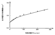
- the gas flow rate FR (cc / min) is a first curve including the heater elements 52a and 52b based on the relationship between the calibration curve obtained in advance shown in FIG. 7, that is, the gas flow rate FS (cm / sec) and the square value of the output voltage.
- the output voltage Vout1 and the output voltage Vout2 from the bridge circuits 56a and 56b it is calculated based on the output voltage output from the bridge circuit where the heater element is located on the upstream side.
- One of the output voltage Vout1 and the output voltage Vout2 is selected based on whether the output voltage Vout of the gas flow velocity measuring circuit 38 is positive or negative.
- the airflow sensor is obtained by multiplying the output voltage Vout1 and the output voltage Vout2 representing the gas flow velocity FS (cm / sec) output from the gas flow velocity measurement circuit 38 by the flow cross-sectional area C (constant) in the airflow sensor 36 obtained in advance.
- the gas flow rate FR (cc / min) flowing through the inside 36 is determined. Note that a gas flow rate FS (cm / sec) may be used instead of the gas flow rate that is the horizontal axis of the relationship shown in FIG.
- the electronic control device 40 is constituted by a so-called microcomputer in which the CPU executes a program stored in advance in the ROM or RAM, and the electronic control device 40 functions as a control function means.
- the control function means includes the following gas flow calculation control unit 70, waveform analysis control unit 72, and heart rate signal evaluation control unit 74, and the heart rate as a signal processing result, the waveform of the heart rate signal SH, the respiratory waveform, and the heart rate waveform. Are displayed on the screen of the display device 76.
- the gas flow calculation control unit 70 squares the gas flow rate FR (cc / min) or gas flow rate FS (cm / sec) flowing through the air flow sensor 36 and the output voltage Vout of the gas flow rate measurement circuit 38 shown in FIG.
- the gas flow rate FR (cc / min) is calculated based on the output voltage Vout (gas flow rate signal) output from the gas flow velocity measurement circuit 38 from the previously stored relationship with the value Vout 2, and the gas flow velocity FS.
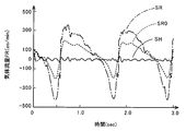
- a change signal of the gas flow rate FR that is, a respiration signal SR representing the lung volume reflecting the respiration motion is output.
- the respiration signal SR of FIG. 8 shows a periodic change of the gas flow rate FR synchronized with respiration, that is, a respiration waveform of the lung 24 of the living body.
- the waveform analysis control unit 72 extracts the heartbeat signal SH indicating the heartbeat waveform from the breathing signal SR on which the heartbeat waveform is superimposed, based on the frequency characteristics of the heartbeat waveform having a higher fundamental frequency than the breathing waveform represented by the breathing signal SR. To do.
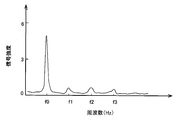
- the waveform analysis control unit 72 performs frequency analysis of the waveform represented by the heartbeat signal SH superimposed on the respiration signal SR in synchronization with the beat of the heart 26 by Fourier transform, and the heartbeat as shown in FIG.
- the fundamental frequency f0, the first harmonic f1, the second harmonic f2, and the third harmonic f3, which are frequency components of the heartbeat signal SH appearing in the frequency spectrum of the signal SH, are obtained in advance, and as shown in FIG.
- the heartbeat signal SH superimposed on the respiration signal SR is collected using, for example, an ECG waveform as a trigger.
- the heartbeat signal SH estimated in this way and the actually measured measurement waveform are displayed so as to overlap each other.
- the waveforms in FIGS. 9 and 10 are obtained from rats.
- the waveform analysis control unit 72 removes a frequency component synchronized with the pulsation of the heart 26 of the living body 10 superimposed on the respiration signal SR from the respiration signal SR output from the airflow sensor 36, that is, the heartbeat signal SH.
- the ventilation component signal SR0 representing the lung volume component derived from the rib cage 18 and the diaphragm 20 of the living body 10 is output.
- the waveform analysis control unit 72 passes the respiration signal SR through, for example, a low-pass filter or a band-pass filter that passes a frequency lower than the frequency component constituting the heartbeat signal SH, so that the respiration heartbeat signal SH shown in FIG.
- the ventilation component signal SR0 representing the lung volume component derived from the rib cage 18 and the diaphragm 20 of the living body 10 is output.
- the waveform analysis control unit 72 extracts a frequency component constituting it from the frequency spectrum of the respiratory signal SR output from the airflow sensor 36, and the heartbeat signal SH is not superimposed by inverse Fourier transform from the frequency component.
- a ventilation component signal SR0 representing a lung volume component derived from the ten thoraxes 18 and the diaphragm 20 is output.
- the heart rate signal evaluation control unit 74 calculates the heart rate HR of the living body 10 from the generation period of the heart rate signal SH, and determines abnormality when the heart rate HR deviates from an upper limit value or a lower limit value of a preset reference range, for example.
- the abnormality of the heart rate HR is output from the screen of the display device 76.
- the heartbeat signal evaluation control unit 74 calculates an amplitude value A of the heartbeat signal SH, and performs abnormality determination when the amplitude value A deviates from an upper limit value or a lower limit value of a preset reference range.
- the abnormality of the amplitude value A is output from the screen of the display device 76.
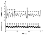
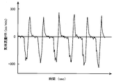
- FIG. 11 is a diagram comparing the heart rate signal SH and ECG obtained simultaneously from a rat. It is shown that the circled numbers 1 to 18 of the peak of the upper heart rate signal SH and the circled numbers 1 to 18 of the R-wave of the lower ECG are preferably matched.
- the heartbeat signal evaluation control unit 74 evaluates functional abnormalities or anatomical abnormalities of the two chambers and two chambers constituting the heart 26 based on the heartbeat signal SH analyzed by the waveform analysis control unit 72, and determines the abnormal state.
- the display shown is output from the screen of the display device 76.
- the heartbeat signal evaluation control unit 74 calculates, for example, a correlation coefficient C between the heartbeat waveform represented by the heartbeat signal SH calculated by the waveform analysis control unit 72 and a plurality of types of abnormality evaluation patterns stored in advance, and the phase A functional abnormality or anatomical abnormality of the two chambers and two chambers constituting the heart 26 indicated by the abnormality evaluation pattern in which the relationship number C exceeds a preset determination value is determined, and the degree of the abnormality is evaluated.
- the heartbeat waveform indicated by the heartbeat signal SH represents the sum of the volume changes in the two chambers and two chambers constituting the heart 26. Therefore, any abnormal function or dissection in the two chambers or two chambers having different volume change timings. This is because it reflects the abnormal information.
- PEEP Positive end-expiratory pressure
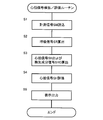
- FIG. 12 is a flowchart for explaining a main part of the control operation of the electronic control unit 40, that is, a heartbeat signal detection / evaluation routine.
- step S1 (hereinafter, step is omitted) corresponding to the gas flow calculation control unit, the output voltage Vout of the gas flow velocity measurement circuit 38, that is, the measurement signal SM corresponding to the gas flow velocity passing through the air flow sensor 36 is at least of the living body 10. It is read in a period longer than one respiratory cycle.
- step S2 corresponding to the gas flow calculation control unit 70, for example, the gas flow rate FR (cc / min) flowing through the air flow sensor 36 and the square value of the output voltage Vout of the gas flow velocity measurement circuit 38 shown in FIG.
- the respiration signal SR representing the change waveform of the gas flow rate FR, that is, the respiration waveform of FIG. 8 is calculated.
- the heartbeat signal SH indicating the heartbeat waveform from the respiration signal SR on which the heartbeat waveform is superimposed. Is extracted.
- the frequency analysis of the waveform represented by the heartbeat signal SH superimposed on the respiration signal SR in synchronization with the beat of the heart 26 is performed by Fourier transform and appears in the frequency spectrum of the heartbeat signal SH as shown in FIG.
- the fundamental frequency f0, the first harmonic f1, the second harmonic f2, and the third harmonic f3, which are frequency components of the heartbeat signal SH, are obtained in advance, and as shown in FIG. 10, inverse Fourier transform is used from these frequency components.
- the heartbeat signal SH is synthesized.
- the heartbeat signal SH superimposed on the respiration signal SR is collected using, for example, an ECG waveform as a trigger.
- the heartbeat signal SH estimated in this way and the actually measured measurement waveform are displayed so as to overlap each other, as if they are the same waveform.
- the waveforms in FIGS. 9 and 10 are obtained from rats. Further, a frequency component synchronized with the pulsation of the heart 26 of the living body 10 superimposed on the respiration signal SR is removed from the respiration signal SR output from the airflow sensor 36, that is, the heartbeat signal SH is removed, and the lungs of the living body 10 are removed.
- the ventilation component signal SR0 representing the lung volume component derived from the thorax 18 and the diaphragm 20 of the living body 10 on which the heartbeat signal SH is not superimposed is calculated, which represents a respiration waveform indicating only the change in the gas flow rate FR corresponding to the volume change due to 24. . Then, by passing the respiratory signal SR through, for example, a low-pass filter or a band-pass filter that passes a frequency lower than the frequency component constituting the heartbeat signal SH, the heartbeat signal SH is removed from the respiratory signal SR shown in FIG. A ventilation component signal SR0 representing a lung volume component derived from the thorax 18 and the diaphragm 20 of the living body 10 on which the heartbeat signal SH is not superimposed is calculated.
- the frequency component which comprises it is extracted from the frequency spectrum of the respiration signal SR output from the airflow sensor 36, and is derived from the rib cage 18 and the diaphragm 20 of the living body 10 on which the heartbeat signal SH is not superimposed by inverse Fourier transform from the frequency component.
- a ventilation component signal SR0 representing the lung volume component of is calculated.
- the heart rate HR of the living body 10 is calculated from the generation period of the heart rate signal SH, and for example, the heart rate HR is an upper limit value or a lower limit value of a preset reference range. Abnormality judgment is performed when it deviates from. Also, the amplitude value A of the heartbeat signal SH is calculated. For example, when the amplitude value A deviates from an upper limit value or a lower limit value of a preset reference range, an abnormality determination of the cardiac output is performed. Further, based on the heartbeat signal SH analyzed by the waveform analysis control unit 72, the abnormal function or anatomical abnormality of the two chambers and two chambers constituting the heart 26 is evaluated.
- a correlation coefficient C between a heartbeat waveform represented by the heartbeat signal SH and a plurality of types of abnormality evaluation patterns stored in advance is calculated, and an abnormality evaluation pattern in which the correlation coefficient C exceeds a preset determination value is indicated.
- a function abnormality or anatomical abnormality of the two chambers and two chambers constituting the heart 26 is determined, and the degree of the abnormality is evaluated.
- an abnormality in the heart rate HR, an amplitude value A (cardiac output), an abnormality in the function of the two chambers and two chambers constituting the heart 26, or an anatomical abnormality is output from the screen of the display device 76.
- an pharmacological effect of the circulatory system drug having a chronotropic action for changing the heart rate but also the pharmacological effect of the circulatory system drug having an inotropic action for changing the cardiac output can be evaluated.
- the medicinal effects of cardiovascular drugs having an inotropic action that changes cardiac output, which was impossible with ECG (electrocardiogram) can be evaluated.
- PEEP Positive end-expiratory pressure
- the waveform analysis control unit 72 superimposes the respiratory signal SR output from the gas flow calculation control unit 70 on the respiratory signal SR.
- a frequency component synchronized with the 26 beats is extracted, and a heartbeat signal SH representing the beat is output.
- the heartbeat signal SH it is possible to easily detect the heartbeat signal SH representing the output of the heart 26 of the living body 10 without using an ECG electrode attached to the living body 10. That is, the heart rate signal SH can be easily obtained even for an infant whose skin is weak and it is difficult to apply the ECG electrode to the skin for a long time for electrocardiographic measurement.
- the heart rate signal SH reflecting the actual volume change of the heart 26, that is, the cardiac output can be obtained, the presence or absence of pulsation of the heart 26 is more reliable than the conventional method using the electrocardiographic induction waveform.
- clinical evaluation of cardiovascular drugs that not only change heart rate HR but also change cardiac output is possible. An effect is also obtained.
- the airflow sensor 36 has, on the inner surface, a heater element 52 composed of an electric resistance element whose electric resistance changes according to temperature, for example, a platinum resistance element or a gold resistance element.
- the formed circuit board film 50 is mounted in a tubular case 46 through which gas flows along the inner wall surface of the circuit substrate film 50 with a predetermined gap S from the inner wall surface, and the electric current of the heater element 52 that is energized and heated.
- the flow rate of gas in the tubular case 46 is detected based on the resistance changing according to the flow rate of gas flowing in the pipe.
- the heater element 52 is arranged along the inner wall shape of the case 46 with a predetermined gap S from the inner wall surface. Since it is attached to the inner wall of the tubular case 46, the flow rate can be measured even with a winding pipe in order to detect the flow rate with a line instead of a point, and between the heater element 52 and the tubular case 46. Since the space for thermal insulation is formed, the responsiveness to heat is determined by the heat capacity of the heater element 52 itself, and a high-speed response can be realized.
- the airflow sensor 36 includes bridge circuits (electric bridges) 56a and 56b including the heater elements 52a and 52b as one of the four resistance elements, and the bridge circuit 56a and From the relationship of FIG. 7 stored in advance between the square value Vout 2 of the output voltage Vout of the gas flow velocity measuring circuit 38 and the gas flow rate FR reflecting the output voltages Vout1 and Vout2 of 56b, the actual gas flow velocity measuring circuit 38 A gas flow rate is detected based on the output voltage Vout. For this reason, there is an advantage that the measurement of the gas flow rate FR is performed with high accuracy.
- the waveform analysis control unit 72 beats the heart 26 of the living body 10 superimposed on the respiration signal SR from the respiration signal SR output from the gas flow calculation control unit 70.
- a frequency component synchronized with the movement is removed, and a ventilation component signal SR0 representing a lung volume component derived from the thorax 18 and the diaphragm 20 of the living body 10 is output.
- the ventilation component signal SR0 and the heart rate signal SH can be obtained simultaneously, there is an advantage that medical work in emergency lifesaving with a time limit can be performed in a short time.
- the heartbeat signal detection device 30 of the present embodiment functional abnormalities or anatomical abnormalities in the two chambers and two chambers constituting the heart 26 are evaluated based on the heartbeat signal SH analyzed by the waveform analysis control unit 72.
- a heartbeat signal evaluation control unit 74 is provided. For this reason, not only the heartbeat signal SH can be obtained, but also the functional abnormality or anatomical abnormality of the two chambers and two chambers constituting the heart 26 can be known based on the heartbeat signal SH.
- FIG. 13 is a perspective view showing the airflow sensor 36 having one heater element 52a, and corresponds to FIG.
- FIG. 14 is a diagram showing a resistance change characteristic TCR showing a resistance value change rate with respect to the temperature of the heater element 52a (change rate when the value of 30 ° C. is set to 1.00).
- FIG. 15 is a circuit diagram showing a configuration of a gas flow rate measurement circuit for driving the airflow sensor 36 having one heater element 52a, and corresponds to FIG. In FIG.
- the gas flow velocity measuring circuit 38 is composed of four resistors R1, R2, R3, and a heater element 52a (resistor Rhd), and a first bridge circuit 56a to which a first bridge power supply voltage Vs1 is applied. And a first measurement circuit 60a that amplifies the output voltage Vout1 of the first bridge circuit 56a by the first feedback amplifier 59a and causes a current corresponding to the signal to flow to the first bridge circuit 56a through the first transistor 58a. .
- the output voltage Vout1 represents the air velocity.
- the resistor R3 is a variable resistor that adjusts the equilibrium state of the first bridge circuit 56a.
- FIG. 16 shows an example in which a pair of detection resistance elements 53a and 53b for measuring the flow rate by changing the resistance value are provided on both sides of the heater element 52a.
- the heater element 52a and the detection resistance elements 53a and 53b are separated from each other. Therefore, the flow rate measurement accuracy is improved as compared with the airflow sensor 36 having a single heater element 52a. be able to.
- a measurement circuit shown in FIG. 6 is connected to the detection resistance elements 53a and 53b, and a heating control circuit for heating the heater element 52a to a constant temperature is connected to the heater element 52a.
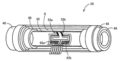
- the airflow sensor 36 having the pair of heater elements 52a and 52b shown in FIG. 4 may be provided with a pair of temperature compensation elements 62a and 62b as shown in FIG.
- FIG. 18 shows a first measurement circuit 50 a that is a part of the measurement circuit 60.
- the temperature compensation elements 62a and 62b have an electric resistance value about 10 times or more that of the heater elements 52a and 52b, and self-heating is suppressed. Since the temperature compensation elements 62a and 62b are formed by sputtering under the same conditions on the same substrate as the heater elements 52a and 52b, they have the same resistance temperature characteristics as the heater elements 52a and 52b.
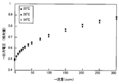
- FIG. 19 shows the output voltage characteristics with respect to the flow rate when the temperature compensation elements 62a and 62b are used by changing the gas temperature.
- FIG. 20 shows the output voltage with respect to the flow rate when the temperature compensation elements 62a and 62b are not used. The characteristics are obtained by changing the gas temperature.
- the output voltage at 34 ° C. decreased by 50% compared to the output voltage at 20 ° C., whereas in FIG. 19, it decreased by 2% or less.
- FIG. 21 is a diagram for explaining the configuration of the airway gas flow rate measuring device 110 and the airflow sensor 126 provided therein, and the function of the electronic control device 112 provided in the airway gas flow rate measuring device 110, respectively.
- the airflow gas flow measurement device 110 includes a bronchoscope 114, an electronic control device 112, a display output device 116, and an airflow sensor 126.
- the airflow sensor 126 is a two heater element type as shown in FIG. 4 of the first embodiment, a one heater element type as shown in FIG. 13 of the second embodiment, a type as shown in FIG. 16 of the third embodiment, and the fourth embodiment. 17 may be any of the two heater element type with a pair of temperature compensation elements as shown in FIG. 17, but the fifth embodiment shows an example constituted by the two heater element type.
- the bronchoscope 114 includes a flexible sheath 122 that is inserted into the airway 120 of the living body 118 as shown in FIG.
- an airflow measurement catheter 124 provided so as to be able to protrude from the distal end through the flexible sheath 122
- an airflow sensor 126 provided at the distal end portion of the airflow measurement catheter 124
- a gas flow rate in the airway is measured using an operation wire 128 provided so as to be able to be protruded from the distal end through the airflow measurement catheter 124 and a diameter-enlarged basket 129 provided at the distal end of the operation wire 128.
- a light source 125 and a CCD camera 127 are provided on the distal end surface of the flexible sheath 122 in addition to the opening of the longitudinal hole 123 for passing the airflow measurement catheter 124.
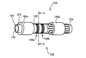
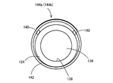
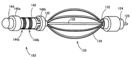
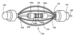
- FIG. 24 shows an enlarged view of the airflow sensor 126 provided at the distal end portion of the airflow measurement catheter 124 protruding from the flexible sheath 122 and the diameter expansion basket 129 protruding from the distal end of the airflow measurement catheter 124. It is a perspective view.
- an enlarged basket 129 is provided at the tip of the airflow measurement catheter 124 at the tip of the airflow sensor 126.
- the diameter-enlarged basket 129 has a plurality of elastic wires 134 whose front end and rear end are bundled together by a front end tip 130 and a rear end tip 132, and is fixed to the front end of the airflow measurement catheter 124.
- the airflow measurement catheter 124 is protruded from the distal end surface of the flexible sheath 122, and the airflow sensor 126 is exposed in the airway 120, as shown in FIG. 25 (b).
- the airflow sensor 126 provided at the distal end of the airflow passage and connected to the flexible sheath 122 side of the enlarged diameter basket 129 is positioned at the center of the airway 120.
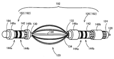
- FIG. 26 is a perspective view illustrating the configuration of the airflow sensor 126
- FIG. 27 is a cross-sectional view of the airflow sensor 126.
- the airflow sensor 126 is wound through a pair of spacers 140 at the distal end portion of the airflow measurement catheter 124 that functions as a first sensor base material, for example, parylene resin or epoxy resin.
- a pair of heater elements 144a and 144b which are formed by photo-etching, etc.
- the pair of annular fixing members 146a and 146b are resin parts that fix the end portion of the circuit base film 142 in the central axis direction to the distal end portion of the airflow measurement catheter 124 by adhering or crimping, and measure the airflow with an adhesive, for example.
- the catheter 124 is fixed to the distal end portion.
- the pair of annular fixing members 146a and 146b are made of heat shrink resin, they are pressed against the distal end portion of the airflow measurement catheter 124 by heat shrinkage.
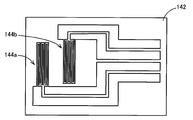
- FIG. 27 shows a pair of spacers 140 interposed between the circuit base film 142 and the outer peripheral surface of the distal end portion of the airflow measurement catheter 124, whereby at least a pair of the circuit base film 142 is provided.
- a gap S is formed between the portion where the heater elements 144a and 144b are formed and the outer peripheral surface of the distal end portion of the airflow measurement catheter 124, and the pair of heater elements 144a and 144b are thermally insulated.
- FIG. 28 shows a developed circuit base film 142 wound through a pair of spacers 140 at the distal end portion of the airflow measurement catheter 124.
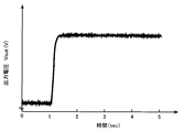
- FIG. 29 shows, for example, changes in resistance values of the heater elements 144a and 144b, that is, changes in the output voltage Vout of the gas flow rate measuring circuit 150 described later, obtained when the gas flow is experimentally started.
- the output voltage Vout in FIG. 29 shows high responsiveness due to the low heat capacity of the heater elements 144a and 144b and the heat insulating action by the gap S.
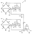
- FIG. 30 is a configuration example of the gas flow velocity measurement circuit 150 and shows a constant temperature type measurement circuit.
- a gas flow velocity measuring circuit 150 is composed of four resistors R1, R2, R3 and a heater element 144a (resistance value Rhd), and a first bridge circuit 152 to which a first bridge power supply voltage Vs1 is applied.
- a first measurement circuit 158 that amplifies the output voltage Vout1 of the first bridge circuit 152 by a first feedback amplifier 156 and causes a current corresponding to the signal to flow to the first bridge circuit 152 by the first transistor 154. .
- the gas flow velocity measurement circuit 150 includes four resistors R5, R6, R7, and a heater element 144b (resistance value Rhu), and a second bridge circuit 162 to which a second bridge power supply voltage Vs2 is applied,
- a second measurement circuit 168 is provided that amplifies the output voltage Vout2 of the two-bridge circuit 162 by the second feedback amplifier 166 and causes a current corresponding to the signal to flow to the second bridge circuit 162 by the second transistor 164.
- the gas flow velocity measurement circuit 150 further includes a differential amplifier 170 that amplifies the difference voltage between the output voltage Vout1 of the first bridge circuit 152 and the output voltage Vout2 of the second bridge circuit 162 and outputs the output voltage Vout. Yes.
- the resistor R3 is a variable resistor that adjusts the balanced state of the first bridge circuit 152
- the resistor R7 is a variable resistor that adjusts the balanced state of the second bridge circuit 162.
- the temperature of the first heater element 144a decreases and its resistance value Rhd decreases.
- the first bridge power supply voltage Vs1 is increased by the feedback amplifier 56 so as to return the first bridge circuit 152 to the initial equilibrium state, the temperature of the first heater element 144a is increased, and the temperature of the first heater element 144a is increased. Maintained at a constant temperature.
- the temperature of the second heater element 144b decreases and its resistance value Rhu decreases, so that the second bridge circuit 162 is brought into the initial equilibrium state.
- the feedback amplifier 166 increases the second bridge power supply voltage Vs2 so that the temperature of the first heater element 144b increases, and the temperature of the heater element 144b is maintained at a constant temperature.
- the output voltage Vout which is output from the differential amplifier 170 and represents the difference voltage between the output voltage Vout1 of the first bridge circuit 152 and the output voltage Vout2 of the second bridge circuit 162, is determined by the gas flow rate measurement circuit 150 by the pair of heater elements 144a.
- a signal that reflects the difference in resistance change at 144b that is, a waveform that represents the direction of forward and backward gas flow in the airway 120. That is, the signal represents the direction of gas flow expressed as a waveform composed of one peak and valley in one respiratory cycle.
- the gas flow rate FR (cc / min) is calculated from a calibration curve obtained in advance similar to that shown in FIG. 7, that is, the relationship between the gas flow rate FS (cm / sec) and the square value of the output voltage, and the heater elements 152a and 152b.
- the output voltage Vout1 and the output voltage Vout2 from the first bridge circuits 156a and 156b including the output voltage Vout2 are calculated based on the output voltage output from the bridge circuit where the heater element is located on the upstream side.
- One of the output voltage Vout1 and the output voltage Vout2 is selected based on whether the output voltage Vout of the gas flow velocity measuring circuit 38 is positive or negative.
- An air flow sensor is obtained by multiplying an output voltage Vout1 and an output voltage Vout2 representing the gas flow velocity FS (cm / sec) output from the gas flow velocity measurement circuit 38 by a flow cross-sectional area C (constant) in the airflow sensor 126 determined in advance.
- a gas flow rate FR (cc / min) flowing through 126 is determined. Note that a gas flow rate FS (cm / sec) may be used instead of the gas flow rate that is the vertical axis of the relationship shown in FIG.
- any one of the output voltage Vout1 of the first bridge circuit 152, the output voltage (V) of the first feedback amplifier 156, the output current of the first feedback amplifier 156, and the output current of the first voltage regulator 154 Since this also reflects the change in the resistance value Rhd of the heater element 144a, the change in the resistance value Rhd of the heater element 144a can be obtained from any of them.
- the second measurement circuit 168 Therefore, the output signals of the first measurement circuit 158 and the second measurement circuit 168 may represent gas flow rates corresponding to them.
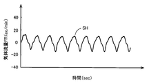
- FIG. 31 shows an experimental example in which the airflow sensor 126 and the gas flow velocity measurement circuit 150 are used to determine the respiration of the rat as the gas flow rate FR (cc / min) passing through the airflow sensor 126.
- the image processing circuit 172 includes an image sensor that converts an image obtained through the CCD camera 127 into an electronic signal, and an image in the airway 120 that is an image converted into an electronic signal by the image sensor. Output to the electronic control unit 112.
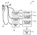
- the electronic control unit 112 is configured by a so-called microcomputer in which the CPU executes a program stored in a ROM or RAM in advance, and includes a gas flow rate calculation control unit 174 as its control function realization means, and a signal processing result
- the gas flow rate in the airway 120 or the gas flow rate FR is displayed on the screen of the display output device 116.
- the gas flow rate calculation control unit 174 calculates the inner diameter of the airway 120 corresponding to the position of the airflow sensor 126 from the image in the airway 120 input from the image processing circuit 172.
- the gas flow rate calculation control unit 174 is a parameter that reflects the gas flow rate FR (cc / min) flowing through the airflow sensor 126 and the output voltages of the first and second bridge circuits 152 and 162 shown in FIG.
- a previously determined relationship between the square value, for example, the square value Vout 2 of the output voltage Vout of the measurement circuit 150 is stored in advance for each inner diameter of the airway 120, and the airway 120 captured from the distal end of the flexible sheath 122.
- the gas flow rate FR is calculated, a gas flow signal representing a change waveform of the gas flow rate FR, and a numerical value representing the gas flow rate FR, for example, an average value, a maximum value, The small value, and outputs to the display output unit 116.
- FIG. 31 shows an example of the waveform of the gas flow signal collected from the rat.
- the airflow measurement catheter 124 is fixed in a state of being wound in a cylindrical shape on the outer peripheral surface of the distal end portion (first sensor base material) of the airflow measurement catheter 124.
- Heater elements (first heater elements) 144a and 144b are formed on the outer peripheral surface of a flexible circuit base film (first circuit base film) 142, and an operation wire 128 passing through the fluid measurement catheter 124 is provided.
- the diameter-enlarging basket 129 that expands by being pushed out positions the airflow sensor (first airflow sensor) 126 in the center of the airway 120, so that one end of the cylindrical sensor base material fixed to the catheter is used.
- the flow resistance in the airway 120 is reduced, and the mucus in the airway 120 is reduced. Since distillation and clogging is difficult to structure occurs, the gas flow rate is accurately and easily measured.
- the circuit base film (first circuit base film) 142 is connected to the distal end portion (first sensor base) of the airflow measurement catheter 124 via the spacer 140. Material) is fixed in a state of being wound in a cylindrical shape, so that at least the heater elements 144a and 144b (first heater elements) of the circuit base film (first circuit base film) 142 are provided. A gap S is formed between the formed portion and the outer peripheral surface of the distal end portion (first sensor base material) of the airflow measurement catheter 124.
- a pair of heater elements 144a and 144b are formed on the circuit base film (first circuit base film) 142. Yes.
- a gas flow rate measuring circuit (first gas flow rate measuring circuit) 150 having a differential amplifier 170 that outputs an output signal corresponding to the output signal difference of the circuit 162, and the first bridge circuit 152 and the second A gas flow rate calculation control unit (first gas flow rate calculation control unit) 174 that calculates a gas flow rate signal (first gas flow rate signal) representing a gas flow rate in the airway 120 based on the output signals Vout1 and Vout2 of the bridge circuit 162; ,included.
- This gas flow rate signal is a waveform that represents the direction of gas flow in one breath as one peak and valley regardless of the direction of gas flow in the airway within one breath cycle. That is, since the gas flow rate in one breath is represented by one peak and valley, the gas flow rate in the airway 120 that is easy to understand can be obtained.
- FIG. 32 is a perspective view for explaining an airflow sensor 182 used in the airway gas flow rate measuring device 110 of another embodiment, and corresponds to FIG.
- the air flow sensor 182 of the present embodiment is configured in the same manner as the air flow sensor 126 described above, but instead of the air flow sensor 126, it is fixed to the tip 130 of the diameter expansion basket 129, and in the measurement state, the diameter expansion is performed.
- the operation wire 128 is connected to the front end tip 130 of the enlarged basket 129 and the rear end tip 132 is slidably attached to the operation wire 128. Is different.
- the tip chip 130 has the same diameter as the airflow measurement catheter 124 that functions as the second sensor base material, but is connected to a separate cylindrical base material 184, and is connected to the cylindrical resin base material 184.
- An airflow sensor 182 configured similarly to the airflow sensor 126 is provided.
- the diameter-enlarged basket 129 is accommodated in the vertical through hole 136 of the airflow measurement catheter 124, and the cylindrical base member 184 or the tip to which the cylindrical base material 184 is fixed.
- the tip 130 is substantially in contact with the distal end surface of the airflow measurement catheter 124.
- the airflow sensor 182 of the present embodiment is connected to the gas flow velocity measuring circuit 150 as in FIGS. 21 and 30 of the above-described embodiment, and the electronic control unit 112 is based on a signal from the gas flow velocity measuring circuit 150.
- the gas flow rate calculation control unit 74 measures the gas flow rate and displays it on the display output device 116.
- a flexible circuit substrate film (second circuit) fixed in a state of being wound in a cylindrical shape on the outer peripheral surface of a columnar substrate (second sensor substrate) 184.
- Heater elements (second heater elements) 144a and 144b are formed on the outer peripheral surface of the base material film 142, and the diameter-expanding basket expands the diameter by operating the operation wire 128 that passes through the fluid measurement catheter 124.
- the 129 positions the airflow sensor (second airflow sensor) 182 in the center of the airway 120, so that a vent hole formed in the side surface of the cylindrical sensor base with one end fixed to the catheter and an opening at the other end Compared to the conventional type in which the measurement gas is passed between the gas and the gas, the flow resistance in the airway 120 is reduced, and the mucus stays and clogs in the airway 120 is less likely to occur. The amount is accurately and easily measured. In particular, since the airflow sensor 182 is located on the distal end side of the diameter expansion basket 129 and the airflow sensor 182 is located on the upstream side of the diameter expansion basket 129 in the expiration period, the gas flow rate in the expiration period is more accurately measured. .
- the circuit base film (second circuit base film) 142 is cylindrical on the outer peripheral surface of the columnar base material (second sensor base) 184 via the spacer 140.
- the heater elements 144a and 144b (second heater elements) of the circuit base film (second circuit base film) 142 and the circle are formed.
- a gap S is formed between the columnar base material (second sensor base material) 184 and the outer peripheral surface.
- the circuit base film (second circuit base film) 142 is formed with a pair of heater elements 144a and 144b (second heater elements).
- a gas flow rate measuring circuit (second gas flow rate measuring circuit) 150 having a differential amplifier 170 that outputs an output signal corresponding to the output signal difference of the circuit 162, and the first bridge circuit 152 and the second A gas flow rate calculation control unit (second gas flow rate calculation control unit) 174 that calculates a gas flow rate signal (second gas flow rate signal) representing a gas flow rate in the airway 120 based on the output signals Vout1 and Vout2 of the bridge circuit 162; Provided. Since this gas flow rate signal represents the gas flow rate in one breath by one peak and valley regardless of the flow direction of the gas in the airway in one breathing cycle, an easily understandable gas flow rate in the airway 120 is obtained.
- FIG. 33 is a perspective view for explaining an airflow sensor 192 used in the airway gas flow rate measuring device 110 of another embodiment of the present invention, and corresponds to FIG.
- the airflow sensor 192 of the present embodiment is configured by combining the airflow sensor 126 of the fifth embodiment and the airflow sensor 182 of the sixth embodiment.
- FIG. 34 is a diagram corresponding to FIG. 21 for explaining the configuration of the in-airway gas flow rate measuring device 110 of the present embodiment.
- a first gas flow velocity measurement circuit 150a and a second gas flow velocity measurement circuit 150b are respectively connected to the air flow sensor 126 and the air flow sensor 182, and are similar to the gas flow velocity measurement circuit 150 of the above-described embodiment.
- Each is composed.
- the first gas flow rate calculation control unit 174a and the second gas flow rate calculation control unit 174b have the same functions as the gas flow rate calculation control unit 174 of the above-described embodiment.
- the same effects as those of the airway gas flow measuring device 110 and the airway gas flow measuring device 180 of the fifth embodiment can be obtained.
- the airflow sensor 182 is located on the distal end side of the enlarged basket 129 and the airflow sensor 182 is located on the upstream side of the enlarged basket 129 in the expiratory section, the gas flow rate in the expiratory section is accurately measured.
- the airflow sensor 126 is located on the proximal end side of the enlarged basket 129 and the airflow sensor 126 is located on the upstream side of the enlarged basket 129 in the intake section, the gas flow rate in the intake section is accurately measured. .
- FIG. 35 is a perspective view for explaining an airflow sensor 202 used in the airway gas flow rate measuring device 110 of another embodiment of the present invention, and corresponds to FIG.
- the airflow sensor 202 of the present embodiment is configured in the same manner as the airflow sensor 126 described above, but unlike the airflow sensor 126, the operation wire is positioned so as to be located at the center in the longitudinal direction of the diameter-enlarged basket 129. 128 and is positioned at the center of the cross section of the enlarged basket 129 in the measurement state, and when the operation wire 128 is pulled, the enlarged basket 129 and the air flow sensor 202 are placed in the air flow measuring catheter 124. It is different in that it is housed in the room.
- the airflow sensor 202 of the present embodiment is connected to the gas flow velocity measuring circuit 150 and the electronic control unit 112 based on a signal from the gas flow velocity measuring circuit 150, as in FIGS.
- the gas flow rate calculation control unit 74 measures the gas flow rate and displays it on the display output device 116.
- the airflow sensor 202 of this embodiment is a cylindrical airflow measurement catheter (first sensor base material) provided integrally or separately at the distal end of the airflow measurement catheter 124 that is passed through the flexible sheath 122. 124, an operation wire 128 that is taken in and out from the distal end of the airflow measurement catheter 124, and a plurality of elastic wires 134 in which the distal end portion and the rear end portion are bundled together, and provided at the distal end portion of the operation wire 126.
- first sensor base material provided integrally or separately at the distal end of the airflow measurement catheter 124 that is passed through the flexible sheath 122.
- an operation wire 128 that is taken in and out from the distal end of the airflow measurement catheter 124
- a plurality of elastic wires 134 in which the distal end portion and the rear end portion are bundled together, and provided at the distal end portion of the operation wire 126.
- a diameter-enlarging basket 129 that expands by being protruded from the distal end of the fluid measuring catheter 124, and a portion of the operation wire 126 that is located in the center of the diameter-enhancing basket 129 in the longitudinal direction in the diameter-enlarging basket 129
- a flexible circuit base film 142 (first circuit base film) fixed in a state of being wound in a cylindrical shape, and a circuit base film 42 and airflow sensor 202 and a first heater element formed on the outer peripheral surface 1 or 2, provided with.
- the airflow sensor 202 of the present embodiment since the airflow sensor 120 is positioned at the center in the airway 120, the flow resistance in the airway 120 is reduced, and the mucus stays in the airway 120 and does not easily clog. Therefore, the gas flow rate is accurately and easily measured.
- the airflow sensor 202 since the airflow sensor 202 is located at the center in the axial direction and the center of the transverse section in the enlarged basket 129, and the airflow sensor 202 is located upstream of the enlarged basket 129 in the expiratory section, the gas in the expiratory section The flow rate is measured more accurately.
- the waveform analysis control unit 72 synthesizes the heartbeat signal SH from the frequency components of the heartbeat synchronization waveform included in the frequency spectrum obtained from the respiratory waveform.
- the heartbeat signal SH may be extracted from the respiratory signal SR through a bandpass filter having a pass frequency band including the fundamental frequency of the heartbeat signal SH.
- the accuracy of the waveform of the heartbeat signal SH extracted in this way is not so high, for example, when the heart rate HR is calculated, the purpose can be sufficiently achieved.
- the cardiac output is estimated from the amplitude of the heartbeat signal SH.
- the tip of the airflow measurement catheter 124 itself functions as the first sensor base or the second sensor base of the airflow sensor 126.
- Another member that is connected to the distal end in the longitudinal direction or that covers the outer peripheral side may function as the first sensor base material or the second sensor of the airflow sensor 126.
- the sensor base material of the airflow sensor 126 may be provided integrally or separately at the distal end portion of the airflow measurement catheter passed through the flexible sheath.
- the enlarged basket and the air flow sensor are connected to each other and provided at the distal end portion of the operation wire 126.
- the air flow sensor 202 the bronchoscope is flexible with the whole being housed in the air flow measuring catheter 124.
- a system in which the diameter-enlarged basket 129 expands by protruding from the distal end of the airflow measurement catheter 124 from the airflow measurement catheter 124 through the operation wire 126 at the site where the airflow is measured through the conductive sheath 122 may be used.
- the airflow sensors 126, 182 and 192 other than the airflow sensor 202 are implemented.
- a temperature compensation circuit is appropriately provided as necessary in order to suppress the influence on the measured value of the gas temperature.
- the airflow sensor 36 described in the first to fourth embodiments and the basket type airflow sensors 126, 182, 192, and 202 described in the fifth to eighth embodiments are infused with a balloon catheter, a swan gantz catheter, and an infusion device. It may be attached to a duct or the like and used to detect the flow rate in the urinary tract, the flow rate in the blood vessel, and the flow rate of the infusion.
Landscapes
- Health & Medical Sciences (AREA)
- Life Sciences & Earth Sciences (AREA)
- Engineering & Computer Science (AREA)
- Physics & Mathematics (AREA)
- Surgery (AREA)
- Medical Informatics (AREA)
- General Health & Medical Sciences (AREA)
- Heart & Thoracic Surgery (AREA)
- Biophysics (AREA)
- Molecular Biology (AREA)
- Pathology (AREA)
- Animal Behavior & Ethology (AREA)
- Biomedical Technology (AREA)
- Public Health (AREA)
- Veterinary Medicine (AREA)
- Physiology (AREA)
- Cardiology (AREA)
- Pulmonology (AREA)
- Signal Processing (AREA)
- Optics & Photonics (AREA)
- Nuclear Medicine, Radiotherapy & Molecular Imaging (AREA)
- Radiology & Medical Imaging (AREA)
- General Physics & Mathematics (AREA)
- Fluid Mechanics (AREA)
- Computer Vision & Pattern Recognition (AREA)
- Artificial Intelligence (AREA)
- Psychiatry (AREA)
- Otolaryngology (AREA)
- Gastroenterology & Hepatology (AREA)
- Mathematical Physics (AREA)
- Measurement Of The Respiration, Hearing Ability, Form, And Blood Characteristics Of Living Organisms (AREA)
- Measuring Pulse, Heart Rate, Blood Pressure Or Blood Flow (AREA)
- Measuring Volume Flow (AREA)
Priority Applications (3)
| Application Number | Priority Date | Filing Date | Title |
|---|---|---|---|
| US15/548,286 US10765377B2 (en) | 2015-02-03 | 2016-02-03 | Heartbeat-signal detecting device |
| JP2016573411A JP6399614B2 (ja) | 2015-02-03 | 2016-02-03 | 心拍信号検出装置 |
| EP16746673.9A EP3254617B1 (en) | 2015-02-03 | 2016-02-03 | Heartbeat signal detecting device and airway flow rate measuring device used for same |
Applications Claiming Priority (4)
| Application Number | Priority Date | Filing Date | Title |
|---|---|---|---|
| JP2015019748 | 2015-02-03 | ||
| JP2015-019747 | 2015-02-03 | ||
| JP2015019747 | 2015-02-03 | ||
| JP2015-019748 | 2015-02-03 |
Publications (1)
| Publication Number | Publication Date |
|---|---|
| WO2016125842A1 true WO2016125842A1 (ja) | 2016-08-11 |
Family
ID=56564181
Family Applications (1)
| Application Number | Title | Priority Date | Filing Date |
|---|---|---|---|
| PCT/JP2016/053293 Ceased WO2016125842A1 (ja) | 2015-02-03 | 2016-02-03 | 心拍信号検出装置、およびそれに用いる気道内気体流量測定装置 |
Country Status (4)
| Country | Link |
|---|---|
| US (1) | US10765377B2 (enExample) |
| EP (1) | EP3254617B1 (enExample) |
| JP (2) | JP6399614B2 (enExample) |
| WO (1) | WO2016125842A1 (enExample) |
Cited By (2)
| Publication number | Priority date | Publication date | Assignee | Title |
|---|---|---|---|---|
| JP2019194538A (ja) * | 2018-05-01 | 2019-11-07 | 国立大学法人名古屋大学 | 流れ測定装置 |
| JP6999141B1 (ja) | 2020-07-06 | 2022-01-18 | 株式会社コスモスウェブ | 生体情報収集システム及びセンサユニット |
Families Citing this family (4)
| Publication number | Priority date | Publication date | Assignee | Title |
|---|---|---|---|---|
| EP3750477A1 (en) * | 2015-05-07 | 2020-12-16 | Ecom Medical, Inc. | Systems and method for fabricating invasive ecg probe |
| US11147515B2 (en) | 2016-02-16 | 2021-10-19 | Ecom Medical, Inc. | Systems and methods for obtaining cardiovascular parameters |
| DE102020131836A1 (de) * | 2020-12-01 | 2022-06-02 | Löwenstein Medical Technology S.A. | Beatmungsgerät und Überwachungssystem |
| CN113273978B (zh) * | 2021-05-21 | 2022-04-29 | 电子科技大学 | 一种基于超宽带雷达的人体呼吸和心跳频率的检测方法 |
Citations (2)
| Publication number | Priority date | Publication date | Assignee | Title |
|---|---|---|---|---|
| JP2007525267A (ja) * | 2004-02-25 | 2007-09-06 | レスメド リミテッド | 睡眠障害呼吸の加圧治療を行なうための装置を使用する心臓の監視及び治療 |
| JP2009168480A (ja) * | 2008-01-11 | 2009-07-30 | Univ Nagoya | 流量センサ |
Family Cites Families (7)
| Publication number | Priority date | Publication date | Assignee | Title |
|---|---|---|---|---|
| US5518002A (en) | 1993-10-22 | 1996-05-21 | Medtrac Technologies, Inc. | Portable electronic spirometric device |
| EP2305116A1 (en) * | 1993-11-05 | 2011-04-06 | ResMed Ltd. | Control of CPAP Treatment |
| US6634363B1 (en) * | 1997-04-07 | 2003-10-21 | Broncus Technologies, Inc. | Methods of treating lungs having reversible obstructive pulmonary disease |
| JP3896405B2 (ja) | 2000-01-24 | 2007-03-22 | 日本光電工業株式会社 | 2電極/3電極変換接続器 |
| JP4587008B2 (ja) | 2000-07-24 | 2010-11-24 | 大名 魏 | 標準12誘導心電図の構築方法および心電図検査装置 |
| US7536908B2 (en) * | 2004-03-11 | 2009-05-26 | Siargo, Ltd. | Micromachined thermal mass flow sensors and insertion type flow meters and manufacture methods |
| GB2462304B (en) | 2008-07-31 | 2010-12-01 | Laerdal Medical As | Device and method for detecting heart beats in a patient using the airway pressure |
-
2016
- 2016-02-03 JP JP2016573411A patent/JP6399614B2/ja active Active
- 2016-02-03 US US15/548,286 patent/US10765377B2/en not_active Expired - Fee Related
- 2016-02-03 WO PCT/JP2016/053293 patent/WO2016125842A1/ja not_active Ceased
- 2016-02-03 EP EP16746673.9A patent/EP3254617B1/en active Active
-
2018
- 2018-08-30 JP JP2018162170A patent/JP6635614B2/ja active Active
Patent Citations (2)
| Publication number | Priority date | Publication date | Assignee | Title |
|---|---|---|---|---|
| JP2007525267A (ja) * | 2004-02-25 | 2007-09-06 | レスメド リミテッド | 睡眠障害呼吸の加圧治療を行なうための装置を使用する心臓の監視及び治療 |
| JP2009168480A (ja) * | 2008-01-11 | 2009-07-30 | Univ Nagoya | 流量センサ |
Cited By (4)
| Publication number | Priority date | Publication date | Assignee | Title |
|---|---|---|---|---|
| JP2019194538A (ja) * | 2018-05-01 | 2019-11-07 | 国立大学法人名古屋大学 | 流れ測定装置 |
| JP7084576B2 (ja) | 2018-05-01 | 2022-06-15 | 国立大学法人東海国立大学機構 | 流れ測定装置 |
| JP6999141B1 (ja) | 2020-07-06 | 2022-01-18 | 株式会社コスモスウェブ | 生体情報収集システム及びセンサユニット |
| JP2022024225A (ja) * | 2020-07-06 | 2022-02-09 | 株式会社コスモスウェブ | 生体情報収集システム及びセンサユニット |
Also Published As
| Publication number | Publication date |
|---|---|
| JP6399614B2 (ja) | 2018-10-03 |
| EP3254617B1 (en) | 2021-03-17 |
| EP3254617A1 (en) | 2017-12-13 |
| EP3254617A4 (en) | 2018-09-12 |
| JPWO2016125842A1 (ja) | 2018-02-22 |
| US20180014792A1 (en) | 2018-01-18 |
| US10765377B2 (en) | 2020-09-08 |
| JP6635614B2 (ja) | 2020-01-29 |
| JP2018202195A (ja) | 2018-12-27 |
Similar Documents
| Publication | Publication Date | Title |
|---|---|---|
| JP6635614B2 (ja) | 気道内気体流量測定装置 | |
| JP6993005B2 (ja) | 肺機能検査装置及びその方法 | |
| JP7291751B2 (ja) | 生理学的パラメータを求めるシステム | |
| US7814906B2 (en) | Method and relevant apparatus for nasal ventilation, particularly for flow-synchronised neonatal assisted ventilation | |
| JP3641431B2 (ja) | 患者監視装置及びその使用法 | |
| JP6247217B2 (ja) | 初期段階の呼気における口呼吸の検出 | |
| JP5181291B2 (ja) | 呼吸機能測定装置 | |
| JP2022002737A (ja) | 睡眠呼吸障害のスクリーニング、診断および監視のためのシステムおよび方法 | |
| US20090306529A1 (en) | Adaptive temperature sensor for breath monitoring device | |
| CN106456053A (zh) | 用于气道疾病评估的呼出气的选择、分段及分析 | |
| JP2011522618A (ja) | 呼吸監視装置に適応可能な温度検出器 | |
| JP2019509791A (ja) | 中心静脈圧マノメトリの使用を介した呼吸パラメーター推定及び非同調検出アルゴリズムの強化 | |
| CN110742612A (zh) | 用于分析的呼吸选择 | |
| US20220218928A1 (en) | Method for evaluating volume responsiveness and medical device | |
| JP2023518805A (ja) | 肺炎またはその他の健康状態を予測、識別、および/または管理するための装置 | |
| JP6912388B2 (ja) | 逐次パラメータ推定を介する患者呼吸状態をモニタリングする非侵襲的方法 | |
| CN114052700B (zh) | 用于确定区域性肺顺应性的装置和方法 | |
| JP5410970B2 (ja) | 哺乳動物に対して使用される人工呼吸器の調節の不具合を検出するための装置 | |
| US20160361012A1 (en) | Methods and applications for detection of breath flow and the system thereof | |
| WO2019152699A1 (en) | Devices and methods for monitoring physiologic parameters | |
| JP2009542391A5 (enExample) | ||
| CN109963503A (zh) | 用于确定用于血压测量设备的校准参数的装置和方法 | |
| WO2018032042A1 (en) | Apparatus and methods for monitoring cardio-respiratory disorders | |
| ES3014959T3 (en) | Method and arrangement for respiratory measurement | |
| JP2019194538A (ja) | 流れ測定装置 |
Legal Events
| Date | Code | Title | Description |
|---|---|---|---|
| 121 | Ep: the epo has been informed by wipo that ep was designated in this application |
Ref document number: 16746673 Country of ref document: EP Kind code of ref document: A1 |
|
| WWE | Wipo information: entry into national phase |
Ref document number: 15548286 Country of ref document: US |
|
| ENP | Entry into the national phase |
Ref document number: 2016573411 Country of ref document: JP Kind code of ref document: A |
|
| NENP | Non-entry into the national phase |
Ref country code: DE |
|
| REEP | Request for entry into the european phase |
Ref document number: 2016746673 Country of ref document: EP |