WO2016125759A1 - 発熱体 - Google Patents
発熱体 Download PDFInfo
- Publication number
- WO2016125759A1 WO2016125759A1 PCT/JP2016/052964 JP2016052964W WO2016125759A1 WO 2016125759 A1 WO2016125759 A1 WO 2016125759A1 JP 2016052964 W JP2016052964 W JP 2016052964W WO 2016125759 A1 WO2016125759 A1 WO 2016125759A1
- Authority
- WO
- WIPO (PCT)
- Prior art keywords
- layer
- less
- water
- mass
- heating element
- Prior art date
- Legal status (The legal status is an assumption and is not a legal conclusion. Google has not performed a legal analysis and makes no representation as to the accuracy of the status listed.)
- Ceased
Links
Images

Classifications
-
- A—HUMAN NECESSITIES
- A61—MEDICAL OR VETERINARY SCIENCE; HYGIENE
- A61F—FILTERS IMPLANTABLE INTO BLOOD VESSELS; PROSTHESES; DEVICES PROVIDING PATENCY TO, OR PREVENTING COLLAPSING OF, TUBULAR STRUCTURES OF THE BODY, e.g. STENTS; ORTHOPAEDIC, NURSING OR CONTRACEPTIVE DEVICES; FOMENTATION; TREATMENT OR PROTECTION OF EYES OR EARS; BANDAGES, DRESSINGS OR ABSORBENT PADS; FIRST-AID KITS
- A61F7/00—Heating or cooling appliances for medical or therapeutic treatment of the human body
- A61F7/02—Compresses or poultices for effecting heating or cooling
- A61F7/03—Compresses or poultices for effecting heating or cooling thermophore, i.e. self-heating, e.g. using a chemical reaction
-
- A—HUMAN NECESSITIES
- A61—MEDICAL OR VETERINARY SCIENCE; HYGIENE
- A61F—FILTERS IMPLANTABLE INTO BLOOD VESSELS; PROSTHESES; DEVICES PROVIDING PATENCY TO, OR PREVENTING COLLAPSING OF, TUBULAR STRUCTURES OF THE BODY, e.g. STENTS; ORTHOPAEDIC, NURSING OR CONTRACEPTIVE DEVICES; FOMENTATION; TREATMENT OR PROTECTION OF EYES OR EARS; BANDAGES, DRESSINGS OR ABSORBENT PADS; FIRST-AID KITS
- A61F7/00—Heating or cooling appliances for medical or therapeutic treatment of the human body
- A61F7/02—Compresses or poultices for effecting heating or cooling
- A61F7/03—Compresses or poultices for effecting heating or cooling thermophore, i.e. self-heating, e.g. using a chemical reaction
- A61F7/032—Compresses or poultices for effecting heating or cooling thermophore, i.e. self-heating, e.g. using a chemical reaction using oxygen from the air, e.g. pocket-stoves
- A61F7/034—Flameless
-
- C—CHEMISTRY; METALLURGY
- C09—DYES; PAINTS; POLISHES; NATURAL RESINS; ADHESIVES; COMPOSITIONS NOT OTHERWISE PROVIDED FOR; APPLICATIONS OF MATERIALS NOT OTHERWISE PROVIDED FOR
- C09K—MATERIALS FOR MISCELLANEOUS APPLICATIONS, NOT PROVIDED FOR ELSEWHERE
- C09K5/00—Heat-transfer, heat-exchange or heat-storage materials, e.g. refrigerants; Materials for the production of heat or cold by chemical reactions other than by combustion
- C09K5/16—Materials undergoing chemical reactions when used
- C09K5/18—Non-reversible chemical reactions
Definitions
- the present invention relates to a heating element.
- Patent Documents 1 to 3 Techniques using heating elements as described in Patent Documents 1 to 3 are known as techniques relating to a heating device that uses heat generated by an oxidation reaction of an oxidizable metal to impart a warm feeling to human skin or the like. .
- Patent Document 1 as a heating element, a powder composition composed of components commonly used in chemical warmers such as iron powder, water-absorbing polymer, silica gel, and saline is filled in a moisture-permeable non-woven bag. Thus, a water vapor generator is described.
- the heating elements described in Patent Document 2 and Patent Document 3 are formed by mixing a heat-generating powder into a slurry by mixing excess water and a thickener and a water-absorbing layer.
- the present invention A heat generating layer containing an oxidizable metal, a water absorbing agent and water; A fiber layer having a maximum water retention of 500% or less; Comprising a structure containing The water content in the heat generation layer is 10% by mass or more and 60% by mass or less, A heating element is provided in which the hardness of the structure measured under the following conditions is 10 g / mm or more and 200 g / mm or less. (conditions) Prepare a test piece obtained by cutting the structure so as to have a square surface with a side of 2 cm, and a cylindrical tube with an inner diameter of 1 cm, so that the central portion of the square surface and the central portion of the cylindrical tube overlap. The test piece is disposed on the cylindrical tube.
- the tip of the plunger is lowered from the upper part of the test piece to the inner center of the cylindrical tube at a speed of 5 cm / min, and a fracture test is performed.
- a rupture test the maximum value of the rupture stress until the test piece breaks is detected, and this is defined as a [g].
- the hardness is obtained by dividing a by the average thickness b [mm] of the heat generating layer.
- the present invention also provides: A heat generating layer containing an oxidizable metal, a water absorbing agent and water; A fiber layer having a maximum water retention of 500% or less; A heating element comprising a structure containing Preparing the fiber layer; Preparing an exothermic powder composition containing an oxidizable metal, a water absorbing agent, and water; Forming a layer containing the exothermic powder composition on top of the fiber layer to obtain a laminate of the fiber layer and the exothermic powder composition; Compressing the laminate and forming the fixed heat generating layer on top of the fiber layer; Including Provided is a method for producing a heating element, wherein the content of water in the heating layer is 10% by mass or more and 60% by mass or less.
- the present invention also provides a heating tool provided with the above heating element.
- the exothermic composition used in the heating element described in Patent Document 1 is conventionally used in chemical warmers, but since the form is powder, the exothermic composition tends to be biased in the bag, As a result, abnormal heat generation may occur, or it may be difficult to generate heat.
- a heat-generating composition that is high in moisture and contains a thickener is laminated on the sheet-like water-absorbing layer, so that it is easy to maintain the sheet shape. Uneven heat generation is less likely to occur.
- abnormal heat generation is prevented even when a large amount of the exothermic composition is filled in one heating tool at the time of manufacture, or even if it is unevenly distributed in a specific location. And can exhibit good heat generation characteristics.
- the target heat generation is achieved by adjusting the water content contained in the water retention layer and the water content contained in the heat generation layer to an appropriate range.
- the characteristic is obtained.
- the water absorption degree of the water retaining layer, the amount of water in the slurry of the heating powder, the viscosity due to the thickener, etc. are appropriately controlled.
- coat it will apply
- the present invention provides a heating element that suppresses the unevenness of the exothermic powder, suppresses the generation of the exothermic temperature in the heat generating layer, and can be easily manufactured with simple manufacturing conditions. Let it be an issue.
- the present inventor is a method in which the water absorbing layer is not used by means different from the techniques described in Patent Document 2 and Patent Document 3 as a heating element in which the bias in the bag of the heat generating composition is suppressed. It was investigated. First, it was examined that the exothermic composition powder was supported on a nonwoven fabric. As a result, it has been found that the powder unevenness cannot be suppressed by merely making the powder exist between the fibers even if the prescriptions such as the moisture content are examined.
- the present inventor can easily fabricate by using a structure in which a heat-generating layer having a certain hardness is provided on the fiber using a hydrophobic fiber layer, and suppresses the unevenness of the heat-generating powder.
- the present inventors have found that a heating element in which the generation temperature unevenness and abnormal heat generation in the heat generation layer are suppressed is provided.
- the present invention it is possible to provide a heating element that can be easily manufactured, suppresses the unevenness of the exothermic powder, and suppresses the generation temperature unevenness and abnormal heat generation in the heat generating layer.
- FIG. 1 is a cross-sectional view schematically showing a heating element 10 according to the embodiment.
- the heating element 10 includes a structure containing a heating layer 11 and a fiber layer 12, and the fiber layer 12 has a characteristic that the maximum water retention rate is 500% or less.
- the heat generating layer 11 contains an oxidizable metal 21, a water absorbing agent 22, and water.
- the heating element 10 has a feature that the structure has a specific hardness as described later.
- the heating element 10 is composed of only two layers of a heating layer 11 and a fiber layer 12.
- the heating layer 11 and the heating layer 11 are within the scope not departing from the object of the present invention.
- a layer other than the heat generating layer 11 and the fiber layer 12 may be provided between the fiber layers 12 or the outermost layer of the heating element 10.
- the heat generating element 10 as shown in FIG. It is preferable to provide a structure in which the fiber layer 12 is laminated so as to be in contact with each other.
- the heating element 10 generates heat due to the oxidation reaction of the oxidizable metal 21 and imparts a sufficient thermal effect, and can have a performance of, for example, a heating temperature of 38 to 70 ° C. in the measurement according to JIS S4100. .
- the oxidizable metal 21 is a metal that generates heat of oxidation reaction, and examples thereof include powders and fibers of one or more metals selected from the group consisting of iron, aluminum, zinc, manganese, magnesium, and calcium. It is done. Among these, iron powder is preferable from the viewpoints of handleability, safety, manufacturing cost, storage stability, and stability. Examples of the iron powder include one or more selected from the group consisting of reduced iron powder and atomized iron powder.
- the oxidizable metal 21 preferably has an average particle size of 10 ⁇ m or more, more preferably 20 ⁇ m or more when powdered, from the viewpoint that the oxidation reaction is efficiently performed. From the same viewpoint, the average particle diameter of the oxidizable metal 21 is preferably 200 ⁇ m or less, and more preferably 150 ⁇ m or less.
- the particle size of the oxidizable metal 21 refers to the maximum length in the form of powder, and is measured by classification using a sieve, a dynamic light scattering method, a laser diffraction method, or the like.
- the average particle diameter of the oxidizable metal 21 is preferably 10 ⁇ m or more and 200 ⁇ m or less, and more preferably 20 ⁇ m or more and 150 ⁇ m or less.
- the content of the oxidizable metal 21 in the heat generating layer 11 is preferably 100 g / m 2 or more in terms of basis weight from the viewpoint of increasing the heat generation temperature of the heat generating element 10 to a desired temperature. 200 g / m 2 or more, more preferably 300 g / m 2 or more. Further, from the same viewpoint, it is preferably 3000 g / m 2 or less, more preferably 2000 g / m 2 or less, and further preferably 1500 g / m 2 or less.
- the content of the oxidizable metal 21 in the heat generating layer 11 can be obtained by an ash test according to JIS P8128 or a thermogravimetric measuring instrument.
- the content of the oxidizable metal 21 in the heat generating layer 11 is preferably 100 g / m 2 or more and 3000 g / m 2 or less, and 200 g / m 2 or more and 2000 g / m 2 or less, expressed as basis weight. More preferably, it is 300 g / m 2 or more and 1500 g / m 2 or less.
- the water absorbing agent 22 has water retention ability, oxygen supply ability, and catalytic ability, and for example, a carbon material can be used.
- a carbon material can be used.
- one or more materials selected from the group consisting of activated carbon, acetylene black, and graphite can be used, but activated carbon is preferably used because it easily adsorbs oxygen when wet.
- 1 type, or 2 or more types of fine powder or small granular materials selected from the group consisting of coconut shell charcoal, wood charcoal, and peat charcoal are more preferably used. From the viewpoint of easily raising the heat generation temperature of the heating element 10 to a desired temperature, wood charcoal is more preferable.
- the water absorbing agent 22 preferably has an average particle size of 10 ⁇ m or more, and more preferably 12 ⁇ m or more. Further, from the same viewpoint, the water absorbing agent 22 preferably has an average particle size of 200 ⁇ m or less, and more preferably 100 ⁇ m or less. In addition, the average particle diameter of the water absorbing agent 22 refers to the maximum length in the form of powder, and is measured by a dynamic light scattering method, a laser diffraction method, or the like. The water absorbing agent 22 is preferably in the form of powder, but may be in a form other than powder, for example, in the form of fiber. The water absorbing agent 22 preferably has an average particle size of 10 ⁇ m or more and 200 ⁇ m or less, and more preferably an average particle size of 12 ⁇ m or more and 100 ⁇ m or less.
- the content of the water-absorbing agent 22 in the heat generating layer 11 is 1 part by mass or more with respect to 100 parts by mass of the oxidizable metal 21 from the viewpoint of sufficiently obtaining water supply to the heat generating layer 11. Is preferably 3 parts by mass or more, more preferably 5 parts by mass or more. Further, the content of the water absorbing agent 22 in the heat generating layer 11 is 40 parts by mass or less with respect to 100 parts by mass of the oxidizable metal 21 from the viewpoint of sufficiently obtaining oxygen supply to the heat generating layer 11. It is preferable that it is 30 parts by mass or less, and more preferably 25 parts by mass or less.
- the content of the water absorbing agent 22 in the heat generating layer 11 is preferably 1 part by mass or more and 40 parts by mass or less with respect to 100 parts by mass of the oxidizable metal 21, and 3 parts by mass. It is more preferably 30 parts by mass or less, and further preferably 5 parts by mass or more and 25 parts by mass or less.
- content of the water absorbing agent 22 in the heat generating layer 11 is preferably 30 g / m 2 or more, more preferably 40 g / m 2 or more, and more preferably 50 g / m 2 or more in terms of basis weight. More preferably it is.
- the content of the water-absorbing agent 22 is preferably 400 g / m 2 or less, more preferably 300 g / m 2 or less, and even more preferably 250 g / m 2 or less, expressed as basis weight. . Further, the content of the water-absorbing agent 22 is preferably 30 g / m 2 or more and 400 g / m 2 or less, more preferably 40 g / m 2 or more and 300 g / m 2 or less, expressed as basis weight, and 50 g / m 2. it is more preferably m is 2 or more 250 g / m 2 or less.
- a water-absorbing polymer or a water-absorbing powder can also be used as the water-absorbing agent 22 for the purpose of further improving the water-absorbing property.
- the water-absorbing polymer include hydrophilic polymers having a cross-linked structure capable of absorbing and retaining a liquid 20 times or more of their own weight.
- the water-absorbing powder include vermiculite, sawdust, silica gel, and pulp powder.
- the content of water in the heat generating layer 11 is 10% by mass or more, preferably 15% by mass or more, and preferably 20% by mass or more from the viewpoint of appropriately controlling the degree of heat generation of the heat generating layer 11. Is more preferable. From the same viewpoint, the content of water in the heat generating layer 11 is 60% by mass or less, preferably 50% by mass or less, and more preferably 40% by mass or less.
- the water content in the heat generating layer 11 can be calculated from the amount of water used when the heat generating layer 11 is produced, or the water contained in the produced heat generating layer 11 is completely evaporated. It can also be calculated from the weight change at that time.
- the exothermic layer 11 can further contain a reaction accelerator.
- a reaction accelerator By including the reaction accelerator, the oxidation reaction of the oxidizable metal 21 can be easily maintained.
- the oxide film formed on the oxidizable metal 21 with the oxidation reaction can be destroyed to promote the oxidation reaction.
- the reaction accelerator include one or more materials selected from the group consisting of alkali metals, alkaline earth metal sulfates, and chlorides. Among them, a group consisting of various chlorides such as sodium chloride, potassium chloride, calcium chloride, magnesium chloride, ferrous chloride and ferric chloride, and sodium sulfate from the viewpoint of excellent conductivity, chemical stability and production cost. It is preferable to use 1 type or 2 types or more materials chosen from these.
- the content of the reaction accelerator in the heat generating layer 11 is preferably 0.5 parts by mass or more with respect to 100 parts by mass of the oxidizable metal 21 from the viewpoint of maintaining a sufficient calorific value for a long time. 1 part by mass or more is more preferable. From the same viewpoint, the content of the reaction accelerator in the heat generating layer 11 is preferably 10 parts by mass or less, more preferably 8 parts by mass or less, and further preferably 7 parts by mass or less. preferable. Further, the content of the reaction accelerator in the heat generating layer 11 is preferably 0.5 parts by mass or more and 10 parts by mass or less, preferably 1 part by mass or more and 8 parts by mass or less, with respect to 100 parts by mass of the oxidizable metal 21. More preferably, it is 1 part by mass or more and 7 parts by mass or less.
- the exothermic layer 11 includes a thickener, a surfactant, a drug, a flocculant, a colorant, a paper strength enhancer, a pH control agent, a bulking agent, etc., as necessary, as long as the effects of the present invention are not impaired. It can also be included.
- the heat generating layer 11 of this embodiment may contain a fiber material in the layer, it is preferable that the quantity is controlled from a viewpoint of suppressing the bias
- the mass of the oxidizable metal 21 per unit area (1 cm 2), per unit area (1 cm 2) of the mass of fibrous material ratio is preferably 0.018 or less, more preferably 0.015 or less, still more preferably 0.01 or less, still more preferably 0.005 or less, More preferably, it is 0.002 or less.
- the mass of the fiber material / the mass of the oxidizable metal is substantially zero (the fiber material is not substantially contained in the intermediate region of the heat generating layer 11).
- examples of the fiber material include a hydrophobic fiber, which will be described later, and a fiber made from a hydrophilic material.
- the intermediate region of the heat generating layer 11 is a point having a distance of 0.4 ⁇ T in the thickness direction when measured from one surface of the heat generating layer 11 when the thickness of the heat generating layer 11 is T.
- the average thickness of the heat generating layer 11 is preferably 0.1 mm or more, more preferably 0.3 mm or more, and further preferably 0.5 mm or more, from the viewpoint of realizing appropriate heat generation performance. From the same viewpoint, the average thickness of the heat generating layer 11 is preferably 2 mm or less, more preferably 1.5 mm or less, and even more preferably 1 mm or less.
- the heat generating body 10 has the laminated structure of the heat generating layer 11 and the fiber layer 12 as shown in FIG.
- the average thickness of the heat generating layer 11 is, for example, JIS 7507 calipers, 25 ° C., 50 In an environment of ⁇ 5% RH, the structure is cut into a size of 1 cm ⁇ 1 cm, and after removing the fiber layer 12 from the laminated structure, the heat generation layer 11 is sandwiched in the thickness direction by jaws, and a pressure of 1. It can be measured at 0N. As will be described later, in the heating element 10 of this embodiment, the oxidizable metal 21, the water absorbing agent 22, and the fiber material constituting the fiber layer 12 are combined at the interface between the heating layer 11 and the fiber layer 12. A composite region (not shown) may be formed. In the present specification, when the composite region as described above is formed, the average thickness of the heat generating layer 11 can be defined after including the composite region.
- the fiber layer 12 with which the heat generating body 10 of this embodiment is provided is demonstrated.
- the fiber layer 12 has a characteristic that the maximum retention rate of water measured by a method described later is 500% or less.
- Such a fiber layer 12 includes, for example, a hydrophobic fiber to be described later, and is preferably composed of a fiber including 90% by mass or more of the hydrophobic fiber.
- the content of the hydrophobic fiber in the fiber layer 12 is more preferably 95 from the viewpoint of suppressing the moisture change of the heat generating layer and the bias of the heat generating powder, and suppressing the generation of the heat generation temperature and the abnormal heat generation in the heat generating layer. It is at least mass%, more preferably at least 98 mass%, even more preferably at least 100 mass%.
- hydrophobic fibers examples include polyethylene terephthalate (PET) fibers that have not been hydrophilized, polyethylene fibers that have not been hydrophilized, and polypropylene that has not been hydrophilized; 1 type selected from the group consisting of PP) fiber, polyester fiber that has not been hydrophilized, nylon fiber that has not been hydrophilized, and acrylic fiber that has not been hydrophilized Alternatively, two or more kinds of fibers can be used. Moreover, even if the hydrophilic fiber is used, it is treated as a hydrophobic fiber in the present embodiment as long as the fiber surface is hydrophobicized by the above-described material or the like and exhibits hydrophobicity. Moreover, this fiber layer 12 may be comprised from the fiber sheet of one layer, for example, and two or more layers may be laminated
- the fibers other than the hydrophobic fibers include fibers made from a hydrophilic material, specifically, rayon, cotton, cupra, hemp, wool, silk, acetate, cellulose, wood pulp, Non-wood pulp fibers; polymers having hydrophilic groups such as hydroxyl groups, carboxyl groups, sulfonic acid groups, amide groups, amino acid groups, such as polyvinyl alcohol, polyethylene glycol, cellulose acetate, polyacrylamide, melamine resins, nylon, hydrophilic Examples thereof include fibers made of a hydrophilic polymer such as polyurethane.
- the fiber layer 12 of the present embodiment can also be constituted by mixing fibers made from these hydrophilic materials as raw materials, less than 10% by mass, preferably less than 5% by mass, more preferably less than 2% by mass.
- the hydrophobic fibers in the fiber layer 12 preferably have an average fiber length of 0.5 mm or more and 0.8 mm or more from the viewpoint of securing the strength of the nonwoven fabric and facilitating fixing of the exothermic powder. preferable.
- the hydrophobic fiber in the fiber layer 12 has an average fiber length of preferably 6 mm or less, more preferably 4 mm or less, from the viewpoint of stably fixing the exothermic powder.
- the hydrophobic fibers in the fiber layer 12 preferably have an average fiber length of 0.5 mm or more and 6 mm or less, and more preferably 0.8 mm or more and 4 mm or less.
- m is the maximum water retention rate (%) of the fiber layer 12
- m 1 is the mass (mg) of the test piece in the standard state
- m 2 is the test piece wetted, dipped or dropped. The latter mass (mg).
- the maximum water retention rate of the fiber layer 12 is preferably 400% or less, more preferably 300% or less, and further preferably 150%, from the viewpoint of further suppressing the deviation of the heat generation temperature of the heat generation layer 11. Or less, more preferably 50% or less.
- the lower limit value of the maximum water retention rate of the fiber layer 12 is not particularly limited, but is, for example, 5% or more, preferably 10% or more.
- the fiber layer 12 has a basis weight of preferably 4 g / m 2 or more, more preferably 10 g / m 2 or more, and further preferably 24 g / m 2 or more.
- the fiber layer 12 preferably has a basis weight of less 600 g / m 2, more preferably 550 g / m 2 or less, and more preferably 500 g / m 2 or less.
- the fiber layer 12 preferably has a basis weight of 4 g / m 2 or more and 600 g / m 2 or less, more preferably 10 g / m 2 or more and 550 g / m 2 or less, and more preferably 24 g / m 2 or more and 500 g. / M 2 or less is more preferable.
- the mass ratio of the mass of the heat generating layer 11 and the mass of the fiber layer 12 (the mass of the heat generating layer / the mass of the fiber layer) can be appropriately set depending on the product to be manufactured. From the viewpoint of conversion, it is preferably 0.5 or more, more preferably 1 or more.
- the mass ratio of the mass of the heat generation layer 11 and the mass of the fiber layer 12 (the mass of the heat generation layer / the mass of the fiber layer) is preferably 100 or less from the viewpoint of suppressing the unevenness of the heat generation powder. It is more preferably 40 or less, and further preferably 30 or less.
- the fiber layer 12 in this embodiment is a fiber layer in which the test value in the following "water absorption test” shows 10,000 seconds or more.
- the water absorption test is a method according to the JIS L1907 (drop method) fiber product water absorption test birec method. Specifically, a 5 ⁇ 5 cm fiber sheet piece (without a heat generation layer) is placed on a 4 cm diameter cylinder, and one drop of water (about 0.04 mL) from a height 1 cm above the fiber sheet. ) After dropping, the time (seconds) required from when the water droplet reaches the fiber sheet piece until the specular reflection of water disappears is measured. The time (seconds) required is taken as the water absorption test value.
- the fiber layer 12 having a larger value obtained by the water absorption test has higher hydrophobicity, and when the heat generation layer 11 and the fiber layer 12 are laminated so as to be in contact with each other, it is difficult to absorb moisture in the heat generation layer 11. Even when the heating element 10 of this embodiment is stored for a long period of time, the moisture change of the heating layer 11 is suppressed, the bias of the heating powder is suppressed, and the bias of the heating temperature and the occurrence of abnormal heat generation in the heating layer 11 are suppressed. It can be a heating element. From this viewpoint, in the heating element 10 of this embodiment, the fiber layer 12 preferably has a water absorption test value of 10,000 seconds or more, more preferably 13000 seconds or more. More preferably, it indicates 15000 seconds or more. In addition, the fiber layer 12 preferably has a water absorption test value of 30000 seconds or less, and 28000 seconds or less, from the viewpoint of having an appropriate affinity with the heat generating layer 11. Is more preferable, and more preferably 25000 seconds or less.
- the heating element 10 of the present embodiment includes a structure containing the above-described heating layer 11 and the fiber layer 12.
- the hardness of the structure is controlled to a specific value.
- this structure has a hardness measured under the following conditions of 10 g / mm or more and 40 g / mm or more from the viewpoint of suppressing variation of components in the entire heat generating layer 11. It is preferable that it is 50 g / mm or more.
- the structure has a hardness measured under the following conditions of 200 g / mm or less, preferably 150 g / mm or less, and more preferably 120 g / mm or less. preferable.
- the hardness of the structure is measured under the following conditions.
- test piece obtained by cutting the structure so as to have a square surface with a side of 2 cm, and a cylindrical tube with an inner diameter of 1 cm, so that the central portion of the square surface and the central portion of the cylindrical tube overlap, The test piece is disposed on the cylindrical tube. Subsequently, using a 1 mm diameter cylindrical plunger, the tip of the plunger is lowered from the upper part of the test piece to the inner center of the cylindrical tube at a speed of 5 cm / min, and a fracture test is performed. In this rupture test, the maximum value of the rupture stress until the test piece breaks is detected, and this is defined as a [g]. The hardness is obtained by dividing a by the average thickness b [mm] of the heat generating layer.
- the heating element 10 has a composite region in which the oxidizable metal 21, the water absorbing agent 22, and the fiber material constituting the fiber layer are combined at the interface between the heat generation layer 11 and the fiber layer 12.
- the thickness including this region is the thickness of the heat generating layer 11. As described above, the hardness can be obtained.
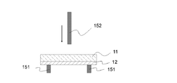
- FIG. 2 is a cross-sectional view schematically showing a structure hardness measuring apparatus used for the above-described measurement.
- a test piece of a structure containing the heat generating layer 11 and the fiber layer 12 is prepared. Separately from this test piece, a cylindrical tube 151 having an inner diameter of 1 cm is prepared, and the central portion of the square surface of the test piece and the central portion of the inner diameter of the cylindrical tube 151 are overlapped on the cylindrical tube 151. Deploy.
- the height of the cylindrical tube 151 is selected to be 20 mm or more and 50 mm or less from the viewpoint of eliminating variations in measured values and ensuring workability. 20 mm or more is preferable from the point of measuring accurately, and 50 mm or less is preferable from the viewpoint of workability.
- a fracture test is performed.
- This test can be performed using a FUDOH rheometer RTC-3010D-CW manufactured by Rheotech Co., Ltd.
- the maximum value of the breaking stress until the test piece breaks is detected, and this is defined as a [g].
- This is divided by the average thickness b [mm] of the heat generating layer 11, that is, a [g] / b [mm] (Formula 1)
- the hardness [g / mm] can be obtained by calculating based on the formula of
- FIG. 1 shows an aspect in which the heat generation layer 11 is provided in direct contact with the fiber layer 12.
- the fiber layer is included in the heat generation layer 11.
- the exothermic layer 11 may be fixed to the fiber layer 12 by entering a part of the fibers in the fiber 12.
- a composite region (not shown) in which a fiber material constituting the oxidizable metal 21, the water absorbing agent 22 and the fiber layer 12 is formed at the interface between the heat generating layer 11 and the fiber layer 12 is formed. It can be.
- the effect of the heat generating body 10 of this embodiment is demonstrated.
- the structure including the heating layer 11 and the fiber layer 12 has a specific hardness, even if the heating layer 11 is cracked by an external force, It can suppress that the component contained in is unevenly distributed. Therefore, heat can be stably generated to a desired temperature over the entire area of the heat generating layer 11.
- the fiber layer 12 has a certain hydrophobicity, the moisture content of the raw material when forming the heating layer 11 is almost reflected in the moisture content in the heating layer 11, and as a result, included in the heating layer 11. It becomes easy to adjust the water content, and the product can be designed easily. That is, it can be said that the heat generating layer 11 of the heating element 10 of the present embodiment can stably generate heat to a desired temperature due to a synergistic effect of the effects exhibited by these configurations.
- the heating element 10 can be manufactured as follows, for example. That is, a heat generation powder composition containing the fiber layer 12, the oxidizable metal 21, the water absorbing agent 22, water, and other optional components is prepared, and a layer containing the heat generation powder composition is formed on the fiber layer 12. Then, a laminated body is formed. Then, it can produce by compressing with a specific pressure and fixing the heat generating layer 11 to the fiber layer 12.
- the exothermic powder composition can be prepared by mixing all the above-mentioned components at once. At this time, in order to suppress the oxidation of the oxidizable metal 21 during the manufacturing process, a means for maintaining a non-oxidizing atmosphere may be employed as necessary.
- the step of compressing and forming the heat generating layer 11 is a process of forming the heat generating layer 11 having a desired hardness from the viewpoint of obtaining the heat generating layer 11 having a desired hardness from 50 kg / cm 2 or more. It is preferable to compress at 200 kg / cm 2 or more.
- the laminate of the fiber layer 12 and the layer containing the heat generating powder composition is preferably compressed at a pressure of 600 kg / cm 2 or less, and a pressure of 400 kg / cm 2 or less. More preferably, the compression is performed.
- the heating element 10 can be manufactured. That is, after the exothermic powder composition is formed into a thin film, compression is performed to obtain a exothermic layer 11 having a plate shape and specific hardness, and the obtained exothermic layer 11 is a fiber layer provided with an adhesive layer. The heating element 10 can also be obtained by sticking to 12.
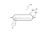
- FIG. 3 is a schematic cross-sectional view showing an example of a heating tool 100 including the heating element 10 shown in FIG.
- the heating tool 100 includes a heating element 10 including a heating layer 11 and a fiber layer 12, and a bag body 20 that is at least partially permeable and accommodates the heating element 10.
- the heating element 10 having the heating layer 11 and the fiber layer 12 is placed in a bag body 20 having air permeability at least partially, and the periphery of the bag body 20 is joined. Takes a sealed structure.
- the bag body 20 is preferably composed of a first bag body sheet 20a and a second bag body sheet 20b.
- the first bag body sheet 20a and the second bag sheet 20b each have an extension area extending outward from the periphery of the heating element 10, and are preferably joined in each extension area. .
- This joining is preferably a continuous airtight joining at the periphery.
- the bag body 20 formed by joining the first bag body sheet 20a and the second bag body sheet 20b has a space for housing the heating element 10 therein.
- the heating element 10 is accommodated in this space.
- the heating element 10 may be in a fixed state with respect to the bag body 20 or may be in a non-fixed state.
- the air permeability of the first bag sheet 20a (according to JIS P8117. The same applies hereinafter) is preferably 50,000 seconds / 100 mL or less, and more preferably 10,000 seconds / 100 mL or less. More preferably, it is 5,000 seconds / 100 mL or less.
- the air permeability of the first bag sheet 20a is preferably 100 seconds / 100 mL or more, more preferably 1,000 seconds / 100 mL or more, and 2,000 seconds / 100 mL or more. Is more preferable.
- the first bag sheet 20a having such air permeability for example, it is preferable to use a porous sheet made of a synthetic resin having moisture permeability but not water permeability. Specifically, a stretched film containing calcium carbonate or the like in polyethylene can be used. When such a porous sheet is used, various fiber sheets including one or more nonwoven fabrics selected from needle punched nonwoven fabric, air-through nonwoven fabric, and spunbonded nonwoven fabric are laminated on the outer surface of the porous sheet. Then, the texture of the first bag sheet 20a may be enhanced.
- the first bag body sheet 20a may be a gas permeable sheet that is partially or entirely permeable, or may be a non-air permeable sheet that does not have gas permeability. A sheet having higher air permeability than the sheet 20b (that is, a sheet having low air permeability) is preferable.
- the air permeability of the first bag sheet 20a is preferably 100 seconds / 100 mL or more and 50,000 seconds / 100 mL or less, more preferably 1,000 seconds / 100 mL or more and 10,000 seconds / 100 mL or less, More preferably, it is 000 seconds / 100 mL or more and 5,000 seconds / 100 mL or less.
- the second bag body sheet 20b may be a gas permeable sheet that is partially or entirely permeable, or may be a non-air permeable sheet that does not have gas permeability.
- a sheet having a lower air permeability than the sheet 20a (that is, a sheet having a higher air permeability) is preferable.
- the second bag sheet 20b is a non-permeable sheet, a single layer or multilayer synthetic resin film, a needle punched nonwoven fabric, an air-through nonwoven fabric, and a spunbond on the outer surface of the single layer or multilayer synthetic resin film
- Various kinds of fiber sheets including one type or two or more types of non-woven fabric selected from non-woven fabrics may be laminated to enhance the texture of the second bag sheet 20b.
- a two-layer film composed of a polyethylene film and a polyethylene terephthalate film, a laminate film composed of a polyethylene film and a nonwoven fabric, a laminate film composed of a polyethylene film and a pulp sheet, etc. are used.
- a film is even more preferred.
- the air permeability of the second bag sheet 20b is set to 5 on the condition that the air permeability of the second bag sheet 20b is lower than the air permeability of the first bag sheet 20a. 000 seconds / 100 mL or more, more preferably 8,000 seconds / 100 mL or more.
- the air permeability of the second bag sheet 20b is preferably 150,000 seconds / 100 mL or less, and more preferably 100,000 seconds / 100 mL or less.
- the air permeability of the second bag sheet 20b is preferably 5,000 seconds / 100 mL or more and 150,000 seconds / 100 mL or less, and is 8,000 seconds / 100 mL or more and 100,000 seconds / 100 mL or less. More preferably.
- the air permeability of the first bag sheet 20a is 5,000 seconds / 100 mL or more and 20,000 seconds / 100 mL or less
- the air permeability of the second bag sheet 20b is 8,000 seconds / 100 mL or more. It is particularly preferable to set it to 100,000 seconds / 100 mL or less.
- the oxidation reaction of the oxidizable metal 21 can be improved, and a large amount of water vapor can be generated from the first bag sheet 20a side.
- the exothermic layer 11 is placed on the first bag sheet 20a side and the fiber layer 12 is placed on the second bag sheet 20b side, and the periphery is hermetically sealed, the oxidation reaction of the oxidizable metal 21 is good.
- the heating element 10 accommodated in the bag body 20 may be one or may be accommodated in a multilayer state in which a plurality of sheets are laminated.
- the bag body 20 may be laminated with various fiber sheets in order to enhance the texture.
- the bag body 20 is further accommodated in an exterior body (not shown) having air permeability, so that the texture and usability are increased. May be increased.
- the exterior body is preferably composed of a first exterior sheet and a second exterior sheet, the first exterior sheet covers one surface of the bag body 20, and the second exterior sheet covers the other side of the bag body 20.
- the first exterior sheet and the second exterior sheet are joined and preferably hermetically joined in an extended region that extends outward from the periphery of the bag body 20. Preferably it is.
- a space for accommodating the bag body 20 is formed inside the exterior body, and the heating element 10 surrounded by the bag body 20 can be accommodated in this space.
- the bag body 20 may be fixed to the exterior body, or may be in an unfixed state.
- the air permeability of the exterior body sheet that is, the first exterior sheet and the second exterior sheet is set to 3,000 seconds / 100 mL or less on condition that the air permeability of the first bag body sheet 20a is higher. It is preferable to set it to 1 second / 100 mL or more and 100 seconds / 100 mL or less. By setting such air permeability, the oxidation reaction of the oxidizable metal 21 can be improved, and a large amount of water vapor can be generated.
- first and second exterior sheets constituting the exterior body have air permeability
- various fiber sheets including nonwoven fabrics the type is not particularly limited. 1 type, or 2 or more types selected from an air through nonwoven fabric and a spun bond nonwoven fabric can be used.
- the heating device 100 can be a steam heating device capable of generating water vapor along with the oxidation reaction of the oxidizable metal 21 because the bag body 20 has air permeability and the exterior body also has air permeability.
- the heating tool 100 has an adhesive layer (not shown) formed by applying an adhesive to the outer surface of the exterior body, for example, the surface of the first exterior sheet or the second exterior sheet constituting the exterior body. You may have.
- the adhesive layer is used to attach the heating tool 100 to human skin or clothing.
- the pressure-sensitive adhesive constituting the pressure-sensitive adhesive layer the same materials as used so far in the technical field including hot melt pressure-sensitive adhesive can be used.
- the heating device 100 is preferably hermetically housed in a packaging bag (not shown) having oxygen barrier properties until just before use.
- the heating tool 100 is applied directly to the human body or attached to clothing and is suitably used for warming the human body.
- Examples of the application site in the human body include shoulders, neck, eyes, eye circumference, waist, elbows, knees, thighs, lower legs, abdomen, lower abdomen, hands, and soles.
- the present invention is applied to various articles and suitably used for heating and keeping warm.
- the heating element 10 described above can be used for a heating tool having a configuration other than that shown in FIG. 3 and for other uses.
- the present invention further discloses the following heating element, manufacturing method, or application.
- a heat generating layer containing an oxidizable metal, a water absorbing agent, and water;
- Comprising a structure containing The water content in the heat generation layer is 10% by mass or more and 60% by mass or less,
- the heat generating body whose hardness measured on condition of the following of the structure is 10 g / mm or more and 200 g / mm or less.
- (conditions) Prepare a test piece obtained by cutting the structure so as to have a square surface with a side of 2 cm, and a cylindrical tube with an inner diameter of 1 cm, so that the central portion of the square surface and the central portion of the cylindrical tube overlap. The test piece is disposed on the cylindrical tube.
- the tip of the plunger is lowered from the upper part of the test piece to the inner center of the cylindrical tube at a speed of 5 cm / min, and a fracture test is performed.
- a rupture test the maximum value of the rupture stress until the test piece breaks is detected, and this is defined as a [g].
- the hardness is obtained by dividing a by the average thickness b [mm] of the heat generating layer.
- the fiber layer has a water absorption test value measured according to JIS L1907 (dropping method) of preferably 10,000 seconds or more, more preferably 13000 seconds or more, and The heating element according to ⁇ 1>, which preferably exhibits 15000 seconds or more.
- the fiber layer has a water absorption test value measured according to JIS L1907 (drop method), preferably 30000 seconds or less, more preferably 28000 seconds or less, and Preferably, the heating element according to ⁇ 1> or ⁇ 2>, which indicates 25000 seconds or less.
- ⁇ 4> The heating element according to any one of ⁇ 1> to ⁇ 3>, wherein the structure is formed by laminating the heating layer and the fiber layer so as to contact each other.
- the structure includes a composite region in which the oxidizable metal, the water-absorbing agent, and a fiber material constituting the fiber layer are combined at an interface between the heat generation layer and the fiber layer.
- the average thickness of the heat generating layer is preferably 0.1 mm or more, more preferably 0.3 mm or more, and further preferably 0.5 mm or more, and any one of ⁇ 1> to ⁇ 5>
- the heating element according to one.
- the average thickness of the heat generating layer is preferably 2 mm or less, more preferably 1.5 mm or less, and even more preferably 1 mm or less, according to any one of ⁇ 1> to ⁇ 6>. Heating element.
- ⁇ 8> The heating element according to any one of ⁇ 1> to ⁇ 7>, wherein the water absorbing agent preferably includes a carbon material.
- the oxidizable metal is in a powder form, and an average particle diameter is preferably 10 ⁇ m or more, more preferably 20 ⁇ m or more.
- ⁇ 10> The heating element according to any one of ⁇ 1> to ⁇ 9>, wherein the oxidizable metal is in a powder form, and an average particle diameter is preferably 200 ⁇ m or less, more preferably 150 ⁇ m or less. .
- the fiber layer is preferably a polyethylene terephthalate (PET) fiber that has not been hydrophilized, a polyethylene fiber that has not been hydrophilized, or a polypropylene that has not been hydrophilized.
- PET polyethylene terephthalate
- PP polypropylene
- the heating element according to any one of ⁇ 1> to ⁇ 10>, which includes one or two or more types of fibers.
- the mass ratio of the mass of the heat generation layer to the mass of the fiber layer is preferably 0.5 or more, more preferably 1 or more.
- the mass ratio of the mass of the heat generation layer to the mass of the fiber layer is preferably 100 or less, more preferably 40 or less, and still more preferably.
- the exothermic layer contains a reaction accelerator, and the content of the reaction accelerator is preferably 0.5 parts by mass or more, more preferably 100 parts by mass of the oxidizable metal content. Is a heating element according to any one of ⁇ 1> to ⁇ 13>, which is 1 part by mass or more.
- the exothermic layer contains a reaction accelerator, and the content of the reaction accelerator is preferably 10 parts by mass or less, more preferably 8 parts per 100 parts by mass of the oxidizable metal.
- the content of the water absorbing agent in the heat generating layer is preferably 1 part by mass or more, more preferably 3 parts by mass or more, with respect to 100 parts by mass of the oxidizable metal.
- the heating element according to any one of ⁇ 1> to ⁇ 15> more preferably 5 parts by mass or more.
- the content of the water absorbing agent in the heat generating layer is preferably 40 parts by mass or less, more preferably 30 parts by mass or less, with respect to 100 parts by mass of the oxidizable metal.
- the fiber layer preferably contains 90% by mass or more of hydrophobic fibers, more preferably 95% by mass or more, further preferably 98% by mass or more, and even more preferably 100% by mass, ⁇ 1 >
- the heating element according to any one of ⁇ 17> is preferably 40 parts by mass or less, more preferably 30 parts by mass or less, with respect to 100 parts by mass of the oxidizable metal.
- the fiber layer preferably contains 90% by mass or more of hydrophobic fibers, more preferably 95% by mass or more, further preferably 98% by mass or more, and even more
- the ratio of the mass of fibrous material per unit area (1 cm 2) (mass / oxidizable fibrous material).
- the mass of the metal is preferably 0.018 or less, more preferably 0.015 or less, still more preferably 0.01 or less, still more preferably 0.005 or less, and still more preferably 0.00.
- the heating element according to any one of ⁇ 1> to ⁇ 18>, which is 002 or less and particularly preferably substantially 0.
- ⁇ 20> The heating element according to any one of ⁇ 1> to ⁇ 19>, wherein the hardness of the structure is preferably 40 g / mm or more, and more preferably 50 g / mm or more.
- the hardness of the structure is preferably 150 g / mm or less, more preferably 120 g / mm or less.
- the content of water in the heating layer is preferably 15% by mass or more, more preferably 20% by mass or more. .
- the maximum water retention rate of the fiber layer is preferably 400% or less, more preferably 300% or less, still more preferably 150% or less, and still more preferably 50% or less.
- ⁇ 25> The heating element according to any one of ⁇ 1> to ⁇ 24>, wherein the maximum retention rate of water in the fiber layer is 5% or more, preferably 10% or more.
- a heating tool comprising the heating element according to any one of ⁇ 1> to ⁇ 25>.
- a heat generating layer containing an oxidizable metal, a water absorbing agent and water A fiber layer having a maximum water retention of 500% or less;
- a heating element comprising a structure containing Preparing the fiber layer; Preparing an exothermic powder composition containing an oxidizable metal, a water absorbing agent, and water; Forming a layer containing the exothermic powder composition on top of the fiber layer to obtain a laminate of the fiber layer and the exothermic powder composition; Compressing the laminate and forming the fixed heat generating layer on top of the fiber layer; Including The method for producing a heating element, wherein the content of water in the heating layer is 10% by mass or more and 60% by mass or less.
- the hardness of the structure measured under the following conditions is 10 g / mm or more, preferably 40 g / mm or more, more preferably 50 g / mm or more, and 200 g / mm or less.
- the method for producing a heating element according to ⁇ 27> preferably 150 g / mm or less, more preferably 120 g / mm or less.
- (conditions) Prepare a test piece obtained by cutting the structure so as to have a square surface with a side of 2 cm, and a cylindrical tube with an inner diameter of 1 cm, so that the central portion of the square surface and the central portion of the cylindrical tube overlap. The test piece is disposed on the cylindrical tube.
- the hardness is obtained by dividing a by the average thickness b [mm] of the heat generating layer.
- the step of forming the heat generating layer is preferably performed by compressing the laminate with a pressure of 50 kg / cm 2 or more, and more preferably compressing with a pressure of 200 kg / cm 2 or more. > Or ⁇ 28>.
- the step of forming the heat generating layer is preferably performed by compressing the laminate with a pressure of 600 kg / cm 2 or less, more preferably with a pressure of 400 kg / cm 2 or less, ⁇ 27 >
- the manufacturing method of the heat generating body as described in any one of ⁇ 29>.
- the fiber layer is preferably a polyethylene terephthalate (PET) fiber that has not been hydrophilized, a polyethylene fiber that has not been hydrophilized, or a polypropylene that has not been hydrophilized.
- PET polyethylene terephthalate
- the fiber layer has a water absorption test value measured according to JIS L1907 (dropping method) of preferably 10,000 seconds or more, more preferably 13,000 seconds or more, and Preferably, the method for producing a heating element according to any one of ⁇ 27> to ⁇ 32>, which indicates 15000 seconds or more.
- the water absorption test value of the fiber layer measured according to JIS L1907 is preferably 30000 seconds or less, more preferably 28000 seconds or less, and even more preferably 25000 seconds or less.
- the exothermic layer contains a reaction accelerator, and the content of the reaction accelerator is preferably 0.5 parts by mass or more with respect to 100 parts by mass of the oxidizable metal, more preferably. Is 1 mass part or more, The manufacturing method of the heat generating body as described in any one of ⁇ 27> thru
- the exothermic layer contains a reaction accelerator, and the content of the reaction accelerator is preferably 10 parts by mass or less, more preferably 8 parts by mass or less, and further preferably 7 parts by mass or less.
- the content of the reaction accelerator is preferably 10 parts by mass or less, more preferably 8 parts by mass or less, and further preferably 7 parts by mass or less.
- the fiber layer preferably contains 90% by mass or more of hydrophobic fibers, more preferably 95% by mass or more, further preferably 98% by mass or more, and even more preferably 100% by mass, ⁇ 27 > The manufacturing method of the heat generating body as described in any one of ⁇ 36>.
- the ratio of the mass of the fiber material per unit area (1 cm 2 ) to the mass of the oxidizable metal per unit area (1 cm 2 ) in the intermediate region of the heat generating layer (mass of fiber material / oxidizability)
- the mass of the metal is preferably 0.018 or less, more preferably 0.015 or less, still more preferably 0.01 or less, still more preferably 0.005 or less, and still more preferably 0.00.
- the heating element production method according to any one of ⁇ 27> to ⁇ 37>, which is 002 or less, and particularly preferably substantially 0.
- ⁇ 39> The heating element according to any one of ⁇ 27> to ⁇ 38>, wherein the content of water in the heating layer is preferably 15% by mass or more, more preferably 20% by mass or more. Manufacturing method.
- ⁇ 40> The heating element according to any one of ⁇ 27> to ⁇ 39>, wherein the content of water in the heating layer is preferably 50% by mass or less, more preferably 40% by mass or less. Manufacturing method.
- ⁇ 41> The maximum water retention rate of the fiber layer is preferably 400% or less, more preferably 300% or less, still more preferably 150% or less, and even more preferably 50% or less.
- ⁇ 27> The manufacturing method of the heat generating body as described in any one of ⁇ 40>.
- ⁇ 42> The method for producing a heating element according to any one of ⁇ 27> to ⁇ 41>, wherein the maximum water retention rate of the fiber layer is 5% or more, preferably 10% or more.
- Examples 1 to 8, Comparative Examples 1 to 6 A heating element having the structure shown in FIG. 1 was produced according to the following procedure.
- Iron powder (Iron powder RKH, DOWA IP CREATION Co., Ltd.) Average particle size 45 ⁇ m -Activated carbon: (Carborafine, manufactured by Nippon Enviro Chemicals Co., Ltd.) Average particle size of 40 ⁇ m
- the nonwoven fabric shown in Table 1 was prepared as a fiber layer, and a 5 cm x 5 cm sheet was produced. On the other hand, it tried to produce the laminated structure by spraying the exothermic powder composition described in Table 1 and compressing it with the pressure described in Table 1. In Comparative Examples 1 and 2, the compression step as described above was not performed.
- Examples of the nonwoven fiber material include fibers having a PP (polypropylene) content of 100% by mass in Examples 1 to 8 and Comparative Examples 1 to 4, fibers having a rayon content of 100% by mass in Comparative Example 5, and Comparative Example 6 Used a fiber having a cellulose content of 100% by mass.
- the maximum retention rate of the water measured according to the above-mentioned method and the measured value of a water absorption test are shown in Table 1.
- one side has a gas permeability of 2500 seconds / 100 mL (first bag sheet), and the other side.
- the first bag sheet and the heat generating layer are in contact with the inside of the bag body whose periphery is made of a non-permeable sheet (second bag sheet) and whose periphery is sealed so that the inner space is 6 cm ⁇ 6 cm.
- a heating tool was produced. The above operation was performed in a nitrogen atmosphere.
- a test piece was produced by cutting out the structure obtained in the process of producing the heating tool in each of the examples and comparative examples 5 and 6 so as to have a square surface with a side of 2 cm.
- a FUDOH rheometer RTC-3010D-CW manufactured by Rheotech Co., Ltd. using a 1 mm diameter cylindrical plunger, the tip of the plunger was lowered from the top of the above test piece at a speed of 5 cm / min, and fractured.
- a test was conducted.
- a cylindrical tube having an inner diameter of 1 cm is prepared, the test piece is arranged on the cylindrical tube so that the central portion of the square surface of the test piece and the central portion of the cylindrical tube overlap, and the plunger was lowered to the inner center of the cylindrical tube.
- the maximum value of the break stress until the test piece broke was detected.
- the average thickness of the heat generating layer was obtained by using a JIS 7507 caliper, cutting the heating element into a size of 1 cm ⁇ 1 cm in an environment of 25 ° C. and 50 ⁇ 5% RH, and removing the fiber layer from the heating element.
- the exothermic layer was sandwiched in the thickness direction with a jaw and measured at a pressure of 1.0 N.
- the hardness of the structure was calculated by dividing the measured value of the maximum breaking stress of the structure by the average thickness of the heat generating layer.
- Adhesion test In order to examine the adhesion between the heat generation layer and the fiber layer, the following evaluation was performed. Table 1 shows the amount of the powder composition spilled in each evaluation. These were performed in a nitrogen atmosphere. Adhesion test 1: When the heating tool was installed vertically on the ground, the amount of powder composition spilled was measured by opening the bag. Adhesion test 2: A heating tool was installed at a height of 10 cm from the ground, dropped vertically 10 times, then opened, and the amount of powder composition spilled was measured.
- thermometer LT8A manufactured by Gram Co., Ltd. was used as a thermometer, and in an air atmosphere, the heating temperature at the upper part of the heating layer and the lower part of the heating layer The exothermic temperature was measured. Specifically, the heating element was installed perpendicularly to the ground, and the surface temperature of the first bag sheet at the portion corresponding to 1 cm upper part and 1 cm lower part from the center of the heating layer was measured. The “heat generation temperature” here is the highest temperature reached. The measurement results are shown in Table 1.
Landscapes
- Health & Medical Sciences (AREA)
- Chemical & Material Sciences (AREA)
- Engineering & Computer Science (AREA)
- Physics & Mathematics (AREA)
- Thermal Sciences (AREA)
- General Health & Medical Sciences (AREA)
- Veterinary Medicine (AREA)
- Vascular Medicine (AREA)
- Life Sciences & Earth Sciences (AREA)
- Animal Behavior & Ethology (AREA)
- Biomedical Technology (AREA)
- Public Health (AREA)
- Heart & Thoracic Surgery (AREA)
- Emergency Medicine (AREA)
- General Chemical & Material Sciences (AREA)
- Chemical Kinetics & Catalysis (AREA)
- Combustion & Propulsion (AREA)
- Materials Engineering (AREA)
- Organic Chemistry (AREA)
- Thermotherapy And Cooling Therapy Devices (AREA)
Abstract
本発明の発熱体(10)は、被酸化性金属(21)、吸水剤(22)及び水を含む発熱層(11)と、水の最大保持率が500%以下である繊維層(12)と、を含有する構造物を備え、発熱層(11)中の水の含有量は、10質量%以上60質量%以下であり、前記構造物の、以下の条件で測定される硬度が10g/mm以上200g/mm以下である。 (条件) 前記構造物を一辺2cmの正方形の面を有するように切り出した試験片と、内径1cmの円筒管を用意し、前記正方形の面の中心部と、前記円筒管の中央部とが重なるようにして、前記円筒管上に前記試験片を配置する。 続いて、1mm径の円柱形状のプランジャーを用い、前記試験片の上部から前記円筒管の内側中心に前記プランジャーの先端を5cm/minの速度で下降させ、破断試験を行う。 この破断試験にて、前記試験片が破断するまでの破断応力の最大値を検出し、これをa[g]とする。 このaを発熱層(11)の平均厚みb[mm]で除することで、前記硬度を求める。
Description
本発明は、発熱体に関する。
被酸化性金属の酸化反応による発熱を利用し、人間の皮膚等に温感を付与する温熱具に関する技術として、特許文献1~3に記載のような発熱体を用いた技術が知られている。
特許文献1には、発熱体として、鉄粉、吸水性ポリマー、シリカゲル及び食塩水という、一般に化学カイロで使用されている成分からなる粉体の組成物を、透湿性の不織布の袋に充填することにより、水蒸気発生体としたものが記載されている。特許文献2や特許文献3に記載の発熱体は、発熱粉体に過剰の水及び増粘剤を混合してスラリー状としたものと吸水層を積層して形成されている。
本発明は、
被酸化性金属、吸水剤及び水を含む発熱層と、
水の最大保持率が500%以下である繊維層と、
を含有する構造物を備え、
前記発熱層中の水の含有量は、10質量%以上60質量%以下であり、
前記構造物の、以下の条件で測定される硬度が10g/mm以上200g/mm以下である、発熱体を提供する。
(条件)
前記構造物を一辺2cmの正方形の面を有するように切り出した試験片と、内径1cmの円筒管を用意し、前記正方形の面の中心部と、前記円筒管の中央部とが重なるようにして、前記円筒管上に前記試験片を配置する。
続いて、1mm径の円柱形状のプランジャーを用い、前記試験片の上部から前記円筒管の内側中心に前記プランジャーの先端を5cm/minの速度で下降させ、破断試験を行う。
この破断試験にて、前記試験片が破断するまでの破断応力の最大値を検出し、これをa[g]とする。
このaを前記発熱層の平均厚みb[mm]で除することで、前記硬度を求める。
被酸化性金属、吸水剤及び水を含む発熱層と、
水の最大保持率が500%以下である繊維層と、
を含有する構造物を備え、
前記発熱層中の水の含有量は、10質量%以上60質量%以下であり、
前記構造物の、以下の条件で測定される硬度が10g/mm以上200g/mm以下である、発熱体を提供する。
(条件)
前記構造物を一辺2cmの正方形の面を有するように切り出した試験片と、内径1cmの円筒管を用意し、前記正方形の面の中心部と、前記円筒管の中央部とが重なるようにして、前記円筒管上に前記試験片を配置する。
続いて、1mm径の円柱形状のプランジャーを用い、前記試験片の上部から前記円筒管の内側中心に前記プランジャーの先端を5cm/minの速度で下降させ、破断試験を行う。
この破断試験にて、前記試験片が破断するまでの破断応力の最大値を検出し、これをa[g]とする。
このaを前記発熱層の平均厚みb[mm]で除することで、前記硬度を求める。
また、本発明は、
被酸化性金属、吸水剤及び水を含む発熱層と、
水の最大保持率が500%以下である繊維層と、
を含有する構造物を備える発熱体の製造方法であって、
前記繊維層を準備する工程と、
被酸化性金属、吸水剤、及び水を含む発熱粉体組成物を準備する工程と、
前記繊維層の上部に、前記発熱粉体組成物を含む層を形成し、前記繊維層と前記発熱粉体組成物との積層体を得る工程と、
前記積層体を圧縮し、前記繊維層の上部に、固定化された前記発熱層を形成する工程と、
を含み、
前記発熱層中の水の含有量は、10質量%以上60質量%以下である、発熱体の製造方法を提供する。
被酸化性金属、吸水剤及び水を含む発熱層と、
水の最大保持率が500%以下である繊維層と、
を含有する構造物を備える発熱体の製造方法であって、
前記繊維層を準備する工程と、
被酸化性金属、吸水剤、及び水を含む発熱粉体組成物を準備する工程と、
前記繊維層の上部に、前記発熱粉体組成物を含む層を形成し、前記繊維層と前記発熱粉体組成物との積層体を得る工程と、
前記積層体を圧縮し、前記繊維層の上部に、固定化された前記発熱層を形成する工程と、
を含み、
前記発熱層中の水の含有量は、10質量%以上60質量%以下である、発熱体の製造方法を提供する。
また、本発明は、上記の発熱体を備える、温熱具を提供する。
本発明の特徴および利点は、以下に述べる好適な実施の形態、およびそれに付随する以下の図面によってさらに明らかになる。
特許文献1に記載の発熱体に使用されている発熱組成物は、従来から化学カイロに用いられていたものであるが、形態が粉体であるため袋内において発熱組成物が偏り易く、その結果異常発熱が発生したり、逆に発熱し難くかったりとムラが生じる可能性があった。
その点、特許文献2や特許文献3に記載の技術においては、高水分でありかつ増粘剤を含有する発熱組成物がシート状の吸水層に積層されており、シート形状を維持し易いため発熱の偏りがある程度生じ難くなっている。また、特許文献3に記載の技術においては、製造時に発熱組成物が1つの温熱具に多量に充填されてしまったり、特定の箇所に多量に偏在してしまったりする場合でも、異常発熱が防止され、良好な発熱特性を発揮することができる。
その点、特許文献2や特許文献3に記載の技術においては、高水分でありかつ増粘剤を含有する発熱組成物がシート状の吸水層に積層されており、シート形状を維持し易いため発熱の偏りがある程度生じ難くなっている。また、特許文献3に記載の技術においては、製造時に発熱組成物が1つの温熱具に多量に充填されてしまったり、特定の箇所に多量に偏在してしまったりする場合でも、異常発熱が防止され、良好な発熱特性を発揮することができる。
ここで、特許文献2や特許文献3に記載の技術においては、保水層に含まれる水の含有量と、発熱層に含まれる水の含有量を適切な範囲に調整することで、目的の発熱特性が得られるようにしている。そのためには、発熱体の製造後に、発熱粉体のスラリー中の水分を吸水シートへ移行させ、発熱層と吸水シート中の水分量を適切な量に安定化させることが必要である。すなわち、一定の品質の発熱体とするためには、発熱体を作製する際に、保水層の吸水度合や、発熱粉体のスラリー中の水分量や増粘剤による粘度等を適切に制御しながら塗布を行うこととなる。
このような状況を鑑み、本発明は、発熱粉体の偏りを抑制し、発熱層における発熱温度の偏りの発生が抑制され、かつ製造条件が簡便で容易に作製できる発熱体を提供することを課題とする。
この点について、本発明者は、発熱組成物の袋内での偏りが抑制された発熱体として、前記特許文献2や特許文献3に記載の技術とは異なる手段で、吸水層を使用しない方法を検討した。まず、不織布に発熱組成物の粉体を担持させることを検討した。その結果、粉体を単に繊維間に存在させるのみでは、水分量等の処方上の検討をしても粉体の偏りを抑制できないことが判明した。また、この場合に親水性の不織布を用いたのでは、発熱体製造後に時間が経つと、発熱組成物中の水分が不織布の繊維へ移行してしまうため、発熱性能を良好に維持できないこと、及び発熱組成物中の水分量が減少することで粉体の偏りがさらに促進されてしまうことが判明した。
検討の結果、本発明者は、疎水性を有する繊維層を用い、この繊維に一定の硬度を有する発熱層を設けるという構成を採用することにより、容易に作製でき、発熱粉体の偏りを抑制し、発熱層における発熱温度の偏りや異常発熱の発生が抑制された発熱体が提供されることを見出した。
本発明によれば、容易に作製でき、発熱粉体の偏りを抑制し、発熱層における発熱温度の偏りや異常発熱の発生が抑制された発熱体を提供することができる。
以下、本発明の実施の形態について、適宜、図面を用いて説明する。尚、すべての図面において、同様な構成要素には同様の符号を付し、適宜説明を省略する。
また、本明細書中において「~」は特に断りがなければ以上から以下を表す。
また、本明細書中において「~」は特に断りがなければ以上から以下を表す。
まず、本実施形態に係る発熱体について説明する。
図1は、実施の形態に係る発熱体10を模式的に示した断面図である。発熱体10は、発熱層11と、繊維層12とを含有する構造物を備えており、繊維層12は水の最大保持率が500%以下である、という特性を有する。また、発熱層11は、被酸化性金属21、吸水剤22、及び水を含有する。
さらに、発熱体10において、後述するように構造物は特定の硬度を有する、という特徴を具備する。
なお、図1には、発熱体10として発熱層11と、繊維層12の二層のみで構成されるものが示されているが、本発明の目的に反しない範囲において、この発熱層11と繊維層12の層間、あるいは発熱体10の最外層に、発熱層11、繊維層12以外の層を備えてもよい。
なお、本実施形態においては、発熱体10の調製のしやすさ、また、発熱層11の発熱の偏りを抑制する観点から、発熱体10として、図1に示されるような、発熱層11と繊維層12とが互いに接するように積層されてなる構造物を備えていることが好ましい。
図1は、実施の形態に係る発熱体10を模式的に示した断面図である。発熱体10は、発熱層11と、繊維層12とを含有する構造物を備えており、繊維層12は水の最大保持率が500%以下である、という特性を有する。また、発熱層11は、被酸化性金属21、吸水剤22、及び水を含有する。
さらに、発熱体10において、後述するように構造物は特定の硬度を有する、という特徴を具備する。
なお、図1には、発熱体10として発熱層11と、繊維層12の二層のみで構成されるものが示されているが、本発明の目的に反しない範囲において、この発熱層11と繊維層12の層間、あるいは発熱体10の最外層に、発熱層11、繊維層12以外の層を備えてもよい。
なお、本実施形態においては、発熱体10の調製のしやすさ、また、発熱層11の発熱の偏りを抑制する観点から、発熱体10として、図1に示されるような、発熱層11と繊維層12とが互いに接するように積層されてなる構造物を備えていることが好ましい。
発熱体10は、被酸化性金属21の酸化反応によって発熱して十分な温熱効果を付与するものであり、JIS S4100に準拠した測定において、たとえば発熱温度38~70℃の性能を有することができる。
被酸化性金属21は、酸化反応熱を発する金属であり、例えば、鉄、アルミニウム、亜鉛、マンガン、マグネシウム、及びカルシウムからなる群から選ばれる1種又は2種以上の金属の粉末や繊維が挙げられる。なかでも、取り扱い性、安全性、製造コスト、保存性及び安定性の点から鉄粉が好ましい。鉄粉としては、例えば、還元鉄粉、及びアトマイズ鉄粉からなる群から選ばれる1種又は2種以上が挙げられる。
被酸化性金属21は、酸化反応が効率的に行われるという観点から、粉末状にした場合の平均粒径が10μm以上であることが好ましく、20μm以上であることがより好ましい。同様の観点から、被酸化性金属21の平均粒径は200μm以下であることが好ましく、150μm以下であることがより好ましい。なお、被酸化性金属21の粒径は、粉体の形態における最大長さをいい、篩による分級、動的光散乱法、レーザー回折法等により測定される。
また、被酸化性金属21を粉末状にした場合、被酸化性金属21の平均粒径は10μm以上200μm以下であることが好ましく、20μm以上150μm以下であることがより好ましい。
また、被酸化性金属21を粉末状にした場合、被酸化性金属21の平均粒径は10μm以上200μm以下であることが好ましく、20μm以上150μm以下であることがより好ましい。
発熱層11中における被酸化性金属21の含有量は、発熱体10の発熱温度を所望の温度に上昇させることができる観点から、坪量で表して、100g/m2以上であることが好ましく、200g/m2以上であることがより好ましく、300g/m2以上であることがさらに好ましい。また、同様の観点から、3000g/m2以下であることが好ましく、2000g/m2以下であることがより好ましく、1500g/m2以下であることがさらに好ましい。
ここで、発熱層11中の被酸化性金属21の含有量は、JIS P8128に準じる灰分試験や、熱重量測定器で求めることができる。他に外部磁場を印加すると磁化が生じる性質を利用して振動試料型磁化測定試験等により定量することができる。
また、発熱層11中における被酸化性金属21の含有量は、坪量で表して、100g/m2以上3000g/m2以下であることが好ましく、200g/m2以上2000g/m2以下であることがより好ましく、300g/m2以上1500g/m2以下であることがさらに好ましい。
ここで、発熱層11中の被酸化性金属21の含有量は、JIS P8128に準じる灰分試験や、熱重量測定器で求めることができる。他に外部磁場を印加すると磁化が生じる性質を利用して振動試料型磁化測定試験等により定量することができる。
また、発熱層11中における被酸化性金属21の含有量は、坪量で表して、100g/m2以上3000g/m2以下であることが好ましく、200g/m2以上2000g/m2以下であることがより好ましく、300g/m2以上1500g/m2以下であることがさらに好ましい。
吸水剤22は、保水能、酸素供給能、及び、触媒能を有するものであり、たとえば、炭素材料を用いることができる。具体的には、活性炭、アセチレンブラック、及び黒鉛からなる群から選ばれる1種又は2種以上の材料を用いることができるが、湿潤時に酸素を吸着しやすいことから、活性炭が好ましく用いられる。また、椰子殻炭、木粉炭、及びピート炭からなる群から選ばれる1種又は2種以上の微細な粉末状物又は小粒状物がより好ましく用いられる。発熱体10の発熱温度を所望の温度に上昇させやすくする観点から、木粉炭がさらに好ましい。
吸水剤22は、被酸化性金属21と均一に混合される観点から、平均粒径が10μm以上であることが好ましく、12μm以上であることがより好ましい。また、同様の観点から、吸水剤22は、平均粒径が200μm以下であることが好ましく、100μm以下であることがより好ましい。
なお、吸水剤22の平均粒径は、粉体の形態における最大長さをいい、動的光散乱法、レーザー回折法等により測定される。吸水剤22は粉体状の形態のものを用いることが好ましいが、粉体状以外の形態のものを用いることもでき、たとえば、繊維状の形態のものを用いることもできる。
また、吸水剤22は、平均粒径が10μm以上200μm以下であることが好ましく、平均粒径が12μm以上100μm以下であることがより好ましい。
なお、吸水剤22の平均粒径は、粉体の形態における最大長さをいい、動的光散乱法、レーザー回折法等により測定される。吸水剤22は粉体状の形態のものを用いることが好ましいが、粉体状以外の形態のものを用いることもでき、たとえば、繊維状の形態のものを用いることもできる。
また、吸水剤22は、平均粒径が10μm以上200μm以下であることが好ましく、平均粒径が12μm以上100μm以下であることがより好ましい。
発熱層11中における吸水剤22の含有量は、発熱層11への水分供給が十分に得られる観点から、被酸化性金属21の含有量100質量部に対して、1質量部以上であることが好ましく、3質量部以上であることがより好ましく、5質量部以上であることがさらに好ましい。また、発熱層11中における吸水剤22の含有量は、発熱層11への酸素供給が十分に得られる観点から、被酸化性金属21の含有量100質量部に対して、40質量部以下であることが好ましく、30質量部以下であることがより好ましく、25質量部以下であることがさらに好ましい。
同様の観点から、発熱層11中における吸水剤22の含有量は、被酸化性金属21の含有量100質量部に対して、1質量部以上40質量部以下であることが好ましく、3質量部以上30質量部以下であることがより好ましく、5質量部以上25質量部以下であることがさらに好ましい。
なお、発熱層11中における吸水剤22の含有量は、坪量で表して、30g/m2以上であることが好ましく、40g/m2以上であることがより好ましく、50g/m2以上であることがさらに好ましい。また、吸水剤22の含有量は、坪量で表して、400g/m2以下であることが好ましく、300g/m2以下であることがより好ましく、250g/m2以下であることがさらに好ましい。また、吸水剤22の含有量は、坪量で表して、30g/m2以上400g/m2以下あることが好ましく、40g/m2以上300g/m2以下であることがより好ましく、50g/m2以上250g/m2以下であることがさらに好ましい。
同様の観点から、発熱層11中における吸水剤22の含有量は、被酸化性金属21の含有量100質量部に対して、1質量部以上40質量部以下であることが好ましく、3質量部以上30質量部以下であることがより好ましく、5質量部以上25質量部以下であることがさらに好ましい。
なお、発熱層11中における吸水剤22の含有量は、坪量で表して、30g/m2以上であることが好ましく、40g/m2以上であることがより好ましく、50g/m2以上であることがさらに好ましい。また、吸水剤22の含有量は、坪量で表して、400g/m2以下であることが好ましく、300g/m2以下であることがより好ましく、250g/m2以下であることがさらに好ましい。また、吸水剤22の含有量は、坪量で表して、30g/m2以上400g/m2以下あることが好ましく、40g/m2以上300g/m2以下であることがより好ましく、50g/m2以上250g/m2以下であることがさらに好ましい。
なお、吸水剤22として、上記の炭素材料の他に、吸水性のさらなる向上を目的として、吸水性を有するポリマーや、吸水性を有する粉体も併用することができる。
吸水性を有するポリマーとしては、自重の20倍以上の液体を吸収・保持できる架橋構造を有する親水性のポリマーが挙げられ、吸水性を有する粉体としては、バーミキュライト、おがくず、シリカゲル、及びパルプ粉末からなる群から選ばれる1種又は2種以上の粉体が挙げられる。吸水剤22として、上記の炭素材料の他に吸水性ポリマーや吸水性粉体を併用する場合、その含有量は、発熱層11中の水100質量部に対して2~10質量部であることが好ましい。
吸水性を有するポリマーとしては、自重の20倍以上の液体を吸収・保持できる架橋構造を有する親水性のポリマーが挙げられ、吸水性を有する粉体としては、バーミキュライト、おがくず、シリカゲル、及びパルプ粉末からなる群から選ばれる1種又は2種以上の粉体が挙げられる。吸水剤22として、上記の炭素材料の他に吸水性ポリマーや吸水性粉体を併用する場合、その含有量は、発熱層11中の水100質量部に対して2~10質量部であることが好ましい。
発熱層11中の水の含有量は、発熱層11の発熱の度合いを適度に制御する観点から、10質量%以上であり、15質量%以上であることが好ましく、20質量%以上であることがより好ましい。同様の観点から、発熱層11中の水の含有量は、60質量%以下であり、50質量%以下であることが好ましく、40質量%以下であることがより好ましい。
なお、この発熱層11中の水の含有量は、発熱層11を作製する際に用いた水の量から計算することもできるし、作製された発熱層11に含まれる水分を完全に蒸発させ、その際における重量変化から計算することもできる。
なお、この発熱層11中の水の含有量は、発熱層11を作製する際に用いた水の量から計算することもできるし、作製された発熱層11に含まれる水分を完全に蒸発させ、その際における重量変化から計算することもできる。
発熱層11は、さらに、反応促進剤を含むことができる。反応促進剤を含ませることで、被酸化性金属21の酸化反応を持続させやすくすることができる。また、反応促進剤を用いることにより、酸化反応に伴い被酸化性金属21に形成される酸化被膜を破壊して、酸化反応を促進することができる。反応促進剤には、例えばアルカリ金属、アルカリ土類金属の硫酸塩、及び塩化物からなる群から選ばれる1種又は2種以上の材料が挙げられる。中でも、導電性、化学的安定性、生産コストに優れる点から、塩化ナトリウム、塩化カリウム、塩化カルシウム、塩化マグネシウム、第1塩化鉄、第2塩化鉄等の各種塩化物、及び硫酸ナトリウムからなる群から選ばれる1種又は2種以上の材料を用いることが好ましい。
発熱層11中の反応促進剤の含有量は、十分な発熱量を長時間持続させる点から、被酸化性金属21の含有量100質量部に対して0.5質量部以上であることが好ましく、1質量部以上であることがより好ましい。また、同様の観点から、発熱層11中の反応促進剤の含有量は、10質量部以下であることが好ましく、8質量部以下であることがより好ましく、7質量部以下であることがさらに好ましい。
また、発熱層11中の反応促進剤の含有量は、被酸化性金属21の含有量100質量部に対して0.5質量部以上10質量部以下であることが好ましく、1質量部以上8質量部以下であることがより好ましく、1質量部以上7質量部以下であることがさらに好ましい。
また、発熱層11中の反応促進剤の含有量は、被酸化性金属21の含有量100質量部に対して0.5質量部以上10質量部以下であることが好ましく、1質量部以上8質量部以下であることがより好ましく、1質量部以上7質量部以下であることがさらに好ましい。
発熱層11には、本発明の効果を阻害しない範囲で、必要に応じて、増粘剤、界面活性剤、薬剤、凝集剤、着色剤、紙力増強剤、pHコントロール剤、嵩高剤等を含むこともできる。
また、本実施形態の発熱層11は、その層中に繊維材を含んでもよいが、発熱層11における発熱温度の偏りをより抑制する観点からは、その量が制御されていることが好ましい。
より具体的に、発熱層11の中間領域において、単位面積(1cm2)あたりの被酸化性金属21の質量に対して、単位面積(1cm2)あたりの繊維材の質量の比率(繊維材の質量/被酸化性金属の質量)が、好ましくは0.018以下であり、より好ましくは0.015以下であり、さらに好ましくは0.01以下であり、さらに好ましくは0.005以下であり、いっそう好ましくは0.002以下である。また、本実施形態においては、(繊維材の質量/被酸化性金属の質量)が実質的に0であること(発熱層11の中間領域に実質的に繊維材が含まれていないこと)が殊更に好ましい。
なお、ここでの繊維材は、後述する疎水性繊維や親水性の素材を原料とする繊維などを挙げることができる。
また、発熱層11の中間領域とは、発熱層11の厚みをTとしたときに、発熱層11全体から、一方の面から計測して厚み方向に0.4×Tの距離を有する点の集合体で形成される領域と、他方の面から計測して厚み方向に0.4×Tの距離を有する点の集合体で形成される領域を除いた領域を指す。
より具体的に、発熱層11の中間領域において、単位面積(1cm2)あたりの被酸化性金属21の質量に対して、単位面積(1cm2)あたりの繊維材の質量の比率(繊維材の質量/被酸化性金属の質量)が、好ましくは0.018以下であり、より好ましくは0.015以下であり、さらに好ましくは0.01以下であり、さらに好ましくは0.005以下であり、いっそう好ましくは0.002以下である。また、本実施形態においては、(繊維材の質量/被酸化性金属の質量)が実質的に0であること(発熱層11の中間領域に実質的に繊維材が含まれていないこと)が殊更に好ましい。
なお、ここでの繊維材は、後述する疎水性繊維や親水性の素材を原料とする繊維などを挙げることができる。
また、発熱層11の中間領域とは、発熱層11の厚みをTとしたときに、発熱層11全体から、一方の面から計測して厚み方向に0.4×Tの距離を有する点の集合体で形成される領域と、他方の面から計測して厚み方向に0.4×Tの距離を有する点の集合体で形成される領域を除いた領域を指す。
発熱層11の平均厚みは、適度な発熱性能を実現する観点から、0.1mm以上であることが好ましく、0.3mm以上であることがより好ましく、0.5mm以上であることがさらに好ましい。同様の観点から、発熱層11の平均厚みは、2mm以下であることが好ましく、1.5mm以下であることがより好ましく、1mm以下であることがさらに好ましい。
なお、発熱体10が図1に示されるような発熱層11と繊維層12との積層構造を有する場合、発熱層11の平均厚みは、たとえば、JIS 7507のノギスを使用し、25℃、50±5%RHの環境下にて、構造物を1cm×1cmの大きさに切断し、この積層構造物から繊維層12を除去した後、発熱層11をジョウにより厚み方向に挟み、圧力1.0Nにて測定することができる。
なお、後述するように、本実施形態の発熱体10は、発熱層11と繊維層12との界面に、被酸化性金属21、吸水剤22及び繊維層12を構成する繊維材が複合された複合領域(図示せず)が形成されることがある。
本明細書において、上記のような複合領域が形成される場合は、この複合領域までを含めた上で、発熱層11の平均厚みを定義することができる。
なお、発熱体10が図1に示されるような発熱層11と繊維層12との積層構造を有する場合、発熱層11の平均厚みは、たとえば、JIS 7507のノギスを使用し、25℃、50±5%RHの環境下にて、構造物を1cm×1cmの大きさに切断し、この積層構造物から繊維層12を除去した後、発熱層11をジョウにより厚み方向に挟み、圧力1.0Nにて測定することができる。
なお、後述するように、本実施形態の発熱体10は、発熱層11と繊維層12との界面に、被酸化性金属21、吸水剤22及び繊維層12を構成する繊維材が複合された複合領域(図示せず)が形成されることがある。
本明細書において、上記のような複合領域が形成される場合は、この複合領域までを含めた上で、発熱層11の平均厚みを定義することができる。
続いて、本実施形態の発熱体10に備えられる繊維層12について説明する。
本実施形態において、繊維層12は、後述の方法により測定される水の最大保持率が500%以下であるという特性を有する。
本実施形態において、繊維層12は、後述の方法により測定される水の最大保持率が500%以下であるという特性を有する。
このような繊維層12は、たとえば、後述する疎水性繊維を含むものであり、好ましくは疎水性繊維を90質量%以上含む繊維から構成されるものである。繊維層12中の疎水性繊維の含有量は、発熱層の水分変化及び発熱粉体の偏りを抑制し、発熱層における発熱温度の偏りや異常発熱の発生を抑制する点から、より好ましくは95質量%以上であり、さらに好ましくは98質量%以上であり、殊更に好ましくは100質量%である。
疎水性繊維としては、たとえば親水化処理をしていないポリエチレンテレフタレート(Polyethylene terephthalate;PET)繊維、親水化処理をしていないポリエチレン(Polyethylene;PE)繊維、親水化処理をしていないポリプロピレン(Polypropylene;PP)繊維、親水化処理をしていないポリエステル(Polyester)繊維、親水化処理をしていないナイロン(Nylon)繊維、親水化処理をしていないアクリル(Acryl)繊維からなる群から選ばれる1種又は2種以上の繊維を用いることができる。また、親水性繊維を用いていても、その繊維表面が上記素材等で疎水化処理されていることにより、疎水性を呈するものであれば、本実施形態における疎水性繊維として扱う。
また、この繊維層12は、例えば、一層の繊維シートから構成されていてもよいし、二層以上が積層されていてもよい。
また、この繊維層12は、例えば、一層の繊維シートから構成されていてもよいし、二層以上が積層されていてもよい。
なお、前記疎水性繊維以外の繊維としては、例えば親水性の素材を原料とする繊維が挙げられ、具体的には、レーヨン、コットン、キュプラ、麻、ウール、シルク、アセテート、セルロース、木材パルプ、非木材パルプ等の繊維;水酸基、カルボキシル基、スルホン酸基、アミド基、アミノ酸基等の親水性基を有するポリマー、例えばポリビニルアルコール、ポリエチレングリコール、酢酸セルロース、ポリアクリルアミド、メラミン樹脂、ナイロン、親水性ポリウレタン等の親水性ポリマーからなる繊維等が挙げられる。本実施形態の繊維層12は、これら親水性の素材を原料とする繊維を10質量%未満、好ましくは5質量%未満、より好ましくは2質量%未満混合させて構成することもできる。
繊維層12における疎水性繊維は、不織布の強度を確保し、発熱粉体を固定化し易くする観点から、その平均繊維長が0.5mm以上であることが好ましく、0.8mm以上であることが好ましい。また、繊維層12における疎水性繊維は、発熱粉体を安定的に固定化する観点から、その平均繊維長が6mm以下であることが好ましく、4mm以下であることがより好ましい。
また、繊維層12における疎水性繊維は、その平均繊維長が0.5mm以上6mm以下であることが好ましく、0.8mm以上4mm以下であることがより好ましい。
また、繊維層12における疎水性繊維は、その平均繊維長が0.5mm以上6mm以下であることが好ましく、0.8mm以上4mm以下であることがより好ましい。
本実施形態において、繊維層12の水の最大保持率は、以下のように測定することができる。
すなわち、JIS L1930:2010一般不織布試験測定方法の「6.9.2保水率」の項目に従い、以下の式に基づき繊維層12の水の最大保持率を求めることができる。
m = 100×(m2-m1)/m1
なお、ここで、mは繊維層12の水の最大保持率(%)、m1は試験片の標準状態での質量(mg)、m2は試験片を湿潤し、水をしたたり落とした後の質量(mg)である。
なお、このJIS L1930:2010一般不織布試験測定方法の「6.9.2保水率」の項目に従うにあたって、100mm×100mmの大きさの試験片が用意できない場合は、より小さなサイズなもの(30mm×30mm)を採取して、測定することができる。
また、試験片が余分な水分を含有している場合には、まず、80℃で20分間乾燥させた後の質量をm1とする。水に浸漬する時間について、15分では試験片から水がしたたり落ちない場合は、試験片から水がしたたり落ちる時間まで水に浸漬することとする。また、試験片を水から取り出して、水がしたたり落ちだしてから、1分後の質量をm2とする。
すなわち、JIS L1930:2010一般不織布試験測定方法の「6.9.2保水率」の項目に従い、以下の式に基づき繊維層12の水の最大保持率を求めることができる。
m = 100×(m2-m1)/m1
なお、ここで、mは繊維層12の水の最大保持率(%)、m1は試験片の標準状態での質量(mg)、m2は試験片を湿潤し、水をしたたり落とした後の質量(mg)である。
なお、このJIS L1930:2010一般不織布試験測定方法の「6.9.2保水率」の項目に従うにあたって、100mm×100mmの大きさの試験片が用意できない場合は、より小さなサイズなもの(30mm×30mm)を採取して、測定することができる。
また、試験片が余分な水分を含有している場合には、まず、80℃で20分間乾燥させた後の質量をm1とする。水に浸漬する時間について、15分では試験片から水がしたたり落ちない場合は、試験片から水がしたたり落ちる時間まで水に浸漬することとする。また、試験片を水から取り出して、水がしたたり落ちだしてから、1分後の質量をm2とする。
また、繊維層12の水の最大保持率は、発熱層11の発熱温度の偏りをより抑制する観点から、好ましくは400%以下であり、より好ましくは300%以下であり、さらに好ましくは150%以下であり、殊更に好ましくは50%以下である。
繊維層12の水の最大保持率の下限値は、特に制限されるものではないが、たとえば5%以上であり、好ましくは10%以上である。
繊維層12の水の最大保持率の下限値は、特に制限されるものではないが、たとえば5%以上であり、好ましくは10%以上である。
また、繊維層12は、その坪量が4g/m2以上であることが好ましく、10g/m2以上であることがより好ましく、24g/m2以上であることがさらに好ましい。また、繊維層12は、その坪量が600g/m2以下であることが好ましく、550g/m2以下であることがより好ましく、500g/m2以下であることがさらに好ましい。
また、繊維層12は、その坪量が4g/m2以上600g/m2以下であることが好ましく、10g/m2以上550g/m2以下であることがより好ましく、24g/m2以上500g/m2以下であることがさらに好ましい。
また、繊維層12は、その坪量が4g/m2以上600g/m2以下であることが好ましく、10g/m2以上550g/m2以下であることがより好ましく、24g/m2以上500g/m2以下であることがさらに好ましい。
本実施形態において、発熱層11の質量と、繊維層12の質量との質量比(発熱層の質量/繊維層の質量)は、作製する製品によって適宜設定することができるが、発熱体をコンパクト化する観点から、0.5以上であることが好ましく、1以上であることがより好ましい。
また、発熱層11の質量と、繊維層12の質量との質量比(発熱層の質量/繊維層の質量)は、発熱粉体の偏りを抑制する観点から、100以下であることが好ましく、40以下であることがより好ましく、30以下であることがさらに好ましい。
また、発熱層11の質量と、繊維層12の質量との質量比(発熱層の質量/繊維層の質量)は、発熱粉体の偏りを抑制する観点から、100以下であることが好ましく、40以下であることがより好ましく、30以下であることがさらに好ましい。
また、本実施形態における繊維層12は、次に示す「吸水性試験」における試験値が10000秒以上を示す繊維層であることが好ましい。
<吸水性試験>
吸水性試験は、JIS L1907(滴下法)繊維製品の吸水性試験バイレック法に準ずる方法である。具体的には、直径4cmの円筒の上に5×5cmの繊維シート片(発熱層を積層していないもの)を置き、繊維シートより1cm上方の高さから水を1滴(約0.04mL)滴下し、水滴が繊維シート片に到達してから水の鏡面反射がなくなるまでに要する時間(秒)を測定する。この要した時間(秒)を吸水性試験値とする。水を滴下した直後に、水を滴下した側とは逆の面から、水の一部あるいは全てが透過した場合は、吸水性試験値は得られない(0秒)とする。測定環境は25℃、40±5%RHとする。なお、ここでいう、水を滴下した側とは逆の面から、水の一部あるいは全てが透過するとは、滴下した水が、滴下された側とは逆の面に水滴となって存在することを意味する。
<吸水性試験>
吸水性試験は、JIS L1907(滴下法)繊維製品の吸水性試験バイレック法に準ずる方法である。具体的には、直径4cmの円筒の上に5×5cmの繊維シート片(発熱層を積層していないもの)を置き、繊維シートより1cm上方の高さから水を1滴(約0.04mL)滴下し、水滴が繊維シート片に到達してから水の鏡面反射がなくなるまでに要する時間(秒)を測定する。この要した時間(秒)を吸水性試験値とする。水を滴下した直後に、水を滴下した側とは逆の面から、水の一部あるいは全てが透過した場合は、吸水性試験値は得られない(0秒)とする。測定環境は25℃、40±5%RHとする。なお、ここでいう、水を滴下した側とは逆の面から、水の一部あるいは全てが透過するとは、滴下した水が、滴下された側とは逆の面に水滴となって存在することを意味する。
かかる吸水性試験によって得られた値が大きい繊維層12ほどその疎水性が高く、発熱層11と繊維層12とが互いに接するように積層する場合は、発熱層11中の水分を吸収し難く、本実施形態の発熱体10を長期保存した場合でも、発熱層11の水分変化が抑制され、発熱粉体の偏りを抑制し、発熱層11における発熱温度の偏りや異常発熱の発生が抑制された発熱体とすることができる。この観点から、本実施形態の発熱体10においては、繊維層12は、その吸水性試験値が10000秒以上を示すものであることが好ましく、13000秒以上を示すものであることがより好ましく、15000秒以上を示すものであることがさらに好ましい。また、繊維層12は、その吸水性試験値が、発熱層11との適度な親和性を持たせる観点から、30000秒以下を示すものであることが好ましく、28000秒以下を示すものであることがより好ましく、25000秒以下を示すものであることがさらに好ましい。
本実施形態の発熱体10は、前述の発熱層11と、繊維層12とを含有する構造物を備えるものである。本実施形態においては、この構造物についての硬度が特定の値に制御される。
具体的に本実施形態においては、この構造物は、発熱層11全域における成分のばらつきを抑制する観点から、以下の条件で測定される硬度が10g/mm以上であり、40g/mm以上であることが好ましく、50g/mm以上であることがより好ましい。同様の観点から、本実施形態においては、構造物は、以下の条件で測定される硬度が200g/mm以下であり、150g/mm以下であることが好ましく、120g/mm以下であることがより好ましい。
なお、構造物の硬度は、次に示す条件により測定する。
具体的に本実施形態においては、この構造物は、発熱層11全域における成分のばらつきを抑制する観点から、以下の条件で測定される硬度が10g/mm以上であり、40g/mm以上であることが好ましく、50g/mm以上であることがより好ましい。同様の観点から、本実施形態においては、構造物は、以下の条件で測定される硬度が200g/mm以下であり、150g/mm以下であることが好ましく、120g/mm以下であることがより好ましい。
なお、構造物の硬度は、次に示す条件により測定する。
(条件)
構造物を一辺2cmの正方形の面を有するように切り出した試験片と、内径1cmの円筒管を用意し、前記正方形の面の中心部と、前記円筒管の中央部とが重なるようにして、前記円筒管上に前記試験片を配置する。
続いて、1mm径の円柱形状のプランジャーを用い、前記試験片の上部から前記円筒管の内側中心に前記プランジャーの先端を5cm/minの速度で下降させ、破断試験を行う。
この破断試験にて、前記試験片が破断するまでの破断応力の最大値を検出し、これをa[g]とする。
このaを前記発熱層の平均厚みb[mm]で除することで、前記硬度を求める。
構造物を一辺2cmの正方形の面を有するように切り出した試験片と、内径1cmの円筒管を用意し、前記正方形の面の中心部と、前記円筒管の中央部とが重なるようにして、前記円筒管上に前記試験片を配置する。
続いて、1mm径の円柱形状のプランジャーを用い、前記試験片の上部から前記円筒管の内側中心に前記プランジャーの先端を5cm/minの速度で下降させ、破断試験を行う。
この破断試験にて、前記試験片が破断するまでの破断応力の最大値を検出し、これをa[g]とする。
このaを前記発熱層の平均厚みb[mm]で除することで、前記硬度を求める。
なお、後述するように、発熱体10においては、発熱層11と繊維層12との界面において、被酸化性金属21、吸水剤22及び繊維層を構成する繊維材が複合された複合領域を有することがある。
上記の硬度の測定条件におけるbの値について、硬度は、この複合領域にも影響を受けるものであるため、この複合領域の厚みがある場合は、この領域を含んだ厚みを発熱層11の厚みであるものとして、上記の硬度を求めることができる。
上記の硬度の測定条件におけるbの値について、硬度は、この複合領域にも影響を受けるものであるため、この複合領域の厚みがある場合は、この領域を含んだ厚みを発熱層11の厚みであるものとして、上記の硬度を求めることができる。
この測定方法について、図2を示しながら説明する。図2には、上記のような測定に用いられる、構造物の硬度の測定装置の概略を断面図にて示している。
この測定においては、まず、発熱層11と繊維層12とを含有する構造物の試験片を用意する。そして、この試験片とは別に、内径1cmの円筒管151を用意し、試験片の正方形の面の中心部と、円筒管151の内径の中央部とが重なるようにして、円筒管151上に配置する。円筒管151の高さは、測定値のばらつきをなくし、また、作業性を担保する観点から、20mm以上50mm以下のものが選ばれる。正確に測定する点から20mm以上が好ましく、作業性の点から50mm以下が好ましい。
続いて、1mm径の円柱形状のプランジャー152を用い、試験片の上部からプランジャー152の先端を5cm/minの速度で下降させ、破断試験を行う。
この試験は、株式会社レオテック製FUDOHレオメーターRTC-3010D-CWを用いて行うことができる。
この試験において、試験片が破断するまでの破断応力の最大値を検出し、これをa[g]とする。これを発熱層11の平均厚みb[mm]で除する、すなわち、
a[g]/b[mm] ・・・(式1)
の式に基づいて計算することで、硬度[g/mm]を求めることができる。
この試験は、株式会社レオテック製FUDOHレオメーターRTC-3010D-CWを用いて行うことができる。
この試験において、試験片が破断するまでの破断応力の最大値を検出し、これをa[g]とする。これを発熱層11の平均厚みb[mm]で除する、すなわち、
a[g]/b[mm] ・・・(式1)
の式に基づいて計算することで、硬度[g/mm]を求めることができる。
本実施形態の発熱体10の具体的な態様として、図1には、発熱層11が繊維層12に直接接して設けられた態様が示されているが、たとえば、発熱層11中に繊維層12中の繊維の一部が入り込むことにより、発熱層11が繊維層12に固定化されていてもよい。本発明の実施態様においては、製造の簡便性、コストの観点から、発熱層11中に繊維層12中の繊維の一部が入り込むことにより固定化されていることが好ましい。
具体的に、発熱層11と繊維層12との界面に、被酸化性金属21、吸水剤22及び繊維層12を構成する繊維材が複合された複合領域(図示せず)が形成されたものとすることができる。
具体的に、発熱層11と繊維層12との界面に、被酸化性金属21、吸水剤22及び繊維層12を構成する繊維材が複合された複合領域(図示せず)が形成されたものとすることができる。
ここで、本実施形態の発熱体10の作用効果について説明する。
本実施形態の発熱体10は、発熱層11と繊維層12とを含有する構造物が特定の硬度を有しているため、仮に発熱層11が外力により割れてしまっても、発熱層11中に含まれる成分が偏在してしまうことを抑制することができる。そのため、発熱層11の全域にわたって、安定的に所望の温度まで発熱をさせることができる。
また、繊維層12は一定の疎水性を有するため、発熱層11を形成させる際における原料の水分含有量が、発熱層11における水分含有量にほぼ反映され、結果として、発熱層11に含まれる水分含有量を調整しやすくなり、容易に製品を設計することができる。
すなわち、これらの構成の奏する効果の相乗効果により、本実施形態の発熱体10の発熱層11は所望の温度まで安定的に発熱できるものといえる。
本実施形態の発熱体10は、発熱層11と繊維層12とを含有する構造物が特定の硬度を有しているため、仮に発熱層11が外力により割れてしまっても、発熱層11中に含まれる成分が偏在してしまうことを抑制することができる。そのため、発熱層11の全域にわたって、安定的に所望の温度まで発熱をさせることができる。
また、繊維層12は一定の疎水性を有するため、発熱層11を形成させる際における原料の水分含有量が、発熱層11における水分含有量にほぼ反映され、結果として、発熱層11に含まれる水分含有量を調整しやすくなり、容易に製品を設計することができる。
すなわち、これらの構成の奏する効果の相乗効果により、本実施形態の発熱体10の発熱層11は所望の温度まで安定的に発熱できるものといえる。
つづいて、発熱体10の製造方法の一例について説明する。
発熱体10は、たとえば、以下のようにして製造することができる。すなわち、繊維層12と、被酸化性金属21、吸水剤22、水、その他任意成分を含む発熱粉体組成物を用意し、繊維層12上に、この発熱粉体組成物を含む層を形成し、積層体を形成する。その後、特定の圧力により圧縮し、発熱層11を繊維層12に固定化することにより作製することができる。
発熱体10は、たとえば、以下のようにして製造することができる。すなわち、繊維層12と、被酸化性金属21、吸水剤22、水、その他任意成分を含む発熱粉体組成物を用意し、繊維層12上に、この発熱粉体組成物を含む層を形成し、積層体を形成する。その後、特定の圧力により圧縮し、発熱層11を繊維層12に固定化することにより作製することができる。
発熱粉体組成物は、前述した成分をすべて一度に混合することで調製することができる。このとき、製造過程での被酸化性金属21の酸化を抑制するために、必要に応じて非酸化性雰囲気に保つ手段を採用してもよい。
ここで、圧縮を行い、発熱層11を形成する工程は、所望の硬度を有する発熱層11を得る点から、繊維層12と発熱粉体組成物を含む層の積層体を50kg/cm2以上で圧縮することが好ましく、200kg/cm2以上で圧縮することがより好ましい。また、効率的に発熱層11を得る観点から、繊維層12と発熱粉体組成物を含む層の積層体を600kg/cm2以下の圧力で圧縮することが好ましく、400kg/cm2以下の圧力で圧縮することがより好ましい。
また、上述の方法においては、繊維層12上に発熱粉体組成物を含む層を形成し、得られた積層体を圧縮する方法が採用されているが、この方法とは別に、以下の方法により発熱体10を作製することができる。
すなわち、発熱粉体組成物を薄膜状に形成した上で、圧縮を行い、板状で特定の硬度を有する発熱層11を得、この得られた発熱層11を接着層が設けられた繊維層12に貼付することにより、発熱体10を得ることもできる。
すなわち、発熱粉体組成物を薄膜状に形成した上で、圧縮を行い、板状で特定の硬度を有する発熱層11を得、この得られた発熱層11を接着層が設けられた繊維層12に貼付することにより、発熱体10を得ることもできる。
なお、前者の方法を採用した場合、発熱粉体組成物を含む層を繊維層12上に形成した際に、繊維層12の有する繊維と発熱粉体組成物との間には適度な相互作用が起こる。そのため、この状態から圧縮を行うことにより、発熱層11と繊維層12との間で堅固な連結が達成でき、また、適度な剥離強度を達成することができる。
この詳細なメカニズムは定かではないものの、繊維層12の有する繊維の空隙に、発熱粉体組成物に含まれる粉体の一部が取り込まれ、この状態から圧縮を行うことにより、この繊維の端部が特定の硬度となった発熱層11の塊の中に捕捉され、被酸化性金属21、吸水剤22及び繊維層12を構成する繊維材が複合された複合領域が形成されることが考えられる。
この詳細なメカニズムは定かではないものの、繊維層12の有する繊維の空隙に、発熱粉体組成物に含まれる粉体の一部が取り込まれ、この状態から圧縮を行うことにより、この繊維の端部が特定の硬度となった発熱層11の塊の中に捕捉され、被酸化性金属21、吸水剤22及び繊維層12を構成する繊維材が複合された複合領域が形成されることが考えられる。
続いて、本実施形態に係る温熱具について説明する。
図3は、図1で示す発熱体10を備えた温熱具100の一例を示す模式的な断面図である。図示するように、この温熱具100は、発熱層11と繊維層12とを備える発熱体10と、少なくとも一部に透気性を有し、発熱体10を収容する袋体20とを備える。
図3は、図1で示す発熱体10を備えた温熱具100の一例を示す模式的な断面図である。図示するように、この温熱具100は、発熱層11と繊維層12とを備える発熱体10と、少なくとも一部に透気性を有し、発熱体10を収容する袋体20とを備える。
より具体的には、この温熱具100は、発熱層11と、繊維層12とを有する発熱体10を、少なくとも一部に透気性を有する袋体20に入れて袋体20の周囲が接合され密封された構造をとる。
袋体20は、好ましくは、第一の袋体シート20aと第二の袋体シート20bとから構成される。
第一の袋体シート20aと第二の袋体シート20bとは、発熱体10の周縁から外方に延出する延出域をそれぞれ有し、各延出域において接合されていることが好ましい。この接合は周縁において連続した気密の接合であることが好ましい。第一の袋体シート20aと第二の袋体シート20bとの接合によって形成された袋体20は、その内部に発熱体10を収容するための空間を有している。この空間内に発熱体10が収容されている。発熱体10は、袋体20に対して固定された状態であってもよいし、固定されていない状態であってもよい。
第一の袋体シート20aは、その一部又は全部が透気性を有していることが好ましい。
第一の袋体シート20aの透気度(JIS P8117に準拠する。以下同様。)は、50,000秒/100mL以下であることが好ましく、10,000秒/100mL以下であることがより好ましく、5,000秒/100mL以下であることがさらに好ましい。また、第一の袋体シート20aの透気度は、100秒/100mL以上であることが好ましく、1,000秒/100mL以上であることがより好ましく、2,000秒/100mL以上であることがさらに好ましい。
第一の袋体シート20aの透気度(JIS P8117に準拠する。以下同様。)は、50,000秒/100mL以下であることが好ましく、10,000秒/100mL以下であることがより好ましく、5,000秒/100mL以下であることがさらに好ましい。また、第一の袋体シート20aの透気度は、100秒/100mL以上であることが好ましく、1,000秒/100mL以上であることがより好ましく、2,000秒/100mL以上であることがさらに好ましい。
このような透気度を有する第一の袋体シート20aとしては、例えば透湿性は有するが透水性を有さない合成樹脂製の多孔性シートを用いることが好適である。具体的には、ポリエチレンに炭酸カルシウム等を含有させ延伸したフィルムを用いることができる。かかる多孔性シートを用いる場合には、多孔性シートの外面にニードルパンチ不織布、エアスルー不織布、及び、スパンボンド不織布から選択される1種又は2種以上の不織布を始めとする各種の繊維シートをラミネートして、第一の袋体シート20aの風合いを高めてもよい。第一の袋体シート20aは、その一部又は全部が透気性を有する透気性シートであってもよいし、透気性を有しない非透気性シートであってもよいが、第二の袋体シート20bよりも透気性の高いシート(即ち透気度の低いシート)であることが好ましい。
また、第一の袋体シート20aの透気度は、100秒/100mL以上50,000秒/100mL以下が好ましく、1,000秒/100mL以上10,000秒/100mL以下がより好ましく、2,000秒/100mL以上5,000秒/100mL以下がさらに好ましい。
第二の袋体シート20bは、その一部又は全部が透気性を有する透気性シートであってもよいし、透気性を有しない非透気性シートであってもよいが、第一の袋体シート20aよりも透気性の低いシート(即ち透気度の高いシート)であることが好ましい。
第二の袋体シート20bを非透気性シートとする場合、一層又は多層の合成樹脂製のフィルムや、該一層又は多層の合成樹脂製のフィルムの外面にニードルパンチ不織布、エアスルー不織布、及びスパンボンド不織布から選択される1種又は2種以上の不織布を始めとする各種の繊維シートをラミネートして、第二の袋体シート20bの風合いを高めてもよい。具体的には、ポリエチレンフィルムとポリエチレンテレフタレートフィルムからなる2層フィルム、ポリエチレンフィルムと不織布とからなるラミネートフィルム、ポリエチレンフィルムとパルプシートからなるラミネートフィルムなどが用いられるが、ポリエチレンフィルムとパルプシートからなるラミネートフィルムが殊更に好ましい。
第二の袋体シート20bが透気性シートである場合には、第一の袋体シート20aと同一のものを用いてもよいし、異なるものを用いてもよい。異なるものを用いる場合、第二の袋体シート20bの透気性が、第一の袋体シート20aの透気性よりも低いことを条件として、第二の袋体シート20bの透気度を、5,000秒/100mL以上とすることが好ましく、8,000秒/100mL以上とすることがより好ましい。また、第二の袋体シート20bの透気度は、150,000秒/100mL以下であることが好ましく、100,000秒/100mL以下であることがより好ましい。
また、第二の袋体シート20bの透気度は、5,000秒/100mL以上150,000秒/100mL以下とすることが好ましく、8,000秒/100mL以上100,000秒/100mL以下とすることがより好ましい。
なかでも、第一の袋体シート20aの透気度を5,000秒/100mL以上20,000秒/100mL以下とし、第二の袋体シート20bの透気度を8,000秒/100mL以上100,000秒/100mL以下とすることが殊更好ましい。このような透気度とすることで、被酸化性金属21の酸化反応が良好となる上、第一の袋体シート20a側から多量の水蒸気を発生することを可能とし得る。
発熱層11が第一の袋体シート20a側、繊維層12が第二の袋体シート20b側となるよう、それぞれ入れて、周縁部を密閉シールすると、被酸化性金属21の酸化反応が良好となる上、第一の袋体シート20a側から多量の水蒸気を発生することを可能とし得るため、好ましい。
なかでも、第一の袋体シート20aの透気度を5,000秒/100mL以上20,000秒/100mL以下とし、第二の袋体シート20bの透気度を8,000秒/100mL以上100,000秒/100mL以下とすることが殊更好ましい。このような透気度とすることで、被酸化性金属21の酸化反応が良好となる上、第一の袋体シート20a側から多量の水蒸気を発生することを可能とし得る。
発熱層11が第一の袋体シート20a側、繊維層12が第二の袋体シート20b側となるよう、それぞれ入れて、周縁部を密閉シールすると、被酸化性金属21の酸化反応が良好となる上、第一の袋体シート20a側から多量の水蒸気を発生することを可能とし得るため、好ましい。
袋体20に収容されている発熱体10は、1枚でもよく、複数枚を積層させた多層状態で収容してもよい。
袋体20は、前述のとおり、その風合いを高めるため各種の繊維シートをラミネートしてもよいが、さらに透気性を有する外装体(図示せず)に収容されることで、その風合いや使用性を高めてもよい。外装体は、好ましくは、第一の外装シートと第二の外装シートとから構成され、第一の外装シートにより袋体20の一方の面を覆い、第二の外装シートにより袋体20の他方の面を覆って、袋体20の周縁から外方に延出する延出域において、第一の外装シートと第二の外装シートとが接合され、好ましくは密閉接合されることによって形成されていることが好ましい。これにより、外装体の内部には、袋体20を収容するための空間が形成され、この空間内に袋体20で包囲された発熱体10を収容することができる。袋体20は、外装体に対して固定された状態であってもよいし、非固定状態であってもよい。
外装体シート、すなわち、第一の外装シート及び第二の外装シートの透気度は、第一の袋体シート20aの透気性よりも高いことを条件として、3,000秒/100mL以下に設定することが好ましく、1秒/100mL以上100秒/100mL以下に設定することがより好ましい。このような透気度とすることで、被酸化性金属21の酸化反応が良好となる上、多量の水蒸気を発生することを可能とし得る。
外装体を構成する第一、第二の外装シートは、透気性を有していれば、例えば、不織布を始めとする各種の繊維シート等、種類は特に限定されないが、例えば、ニードルパンチ不織布、エアスルー不織布、スパンボンド不織布から選択される1種又は2種以上を用いることができる。
温熱具100は、袋体20が透気性を有し、外装体も透気性を有することにより、被酸化性金属21の酸化反応とともに水蒸気の発生が可能な蒸気温熱具とすることができる。
温熱具100は、外装体の外面、例えば、外装体を構成する第1の外装シート又は第2の外装シートの表面に、粘着剤が塗工されて形成された粘着層(図示せず)を有していてもよい。粘着層は、温熱具100を人体の肌や衣類等に取り付けるために用いられる。粘着層を構成する粘着剤としては、ホットメルト粘着剤を始めとする当該技術分野において、これまで用いられてきたものと同じ物を用いることができる。
温熱具100は、使用直前まで酸素バリア性を有する包装袋(図示せず)内に密封収容されることが好ましい。
温熱具100は、人体に直接適用されるか、又は衣類に装着されて、人体の加温に好適に用いられる。人体における適用部位としては、例えば、肩、首、目、目の周囲、腰、肘、膝、大腿、下腿、腹、下腹部、手、足裏などが挙げられる。また、人体のほかに、各種の物品に適用されてその加温や保温等にも好適に用いられる。
なお、上記の発熱体10は、図3に示す以外の他の構成の温熱具や、他の用途に用いることもできる。
上述した実施形態に関し、本発明はさらに以下の発熱体、製造方法、或いは用途を開示する。
<1> 被酸化性金属、吸水剤及び水を含む発熱層と、
水の最大保持率が500%以下である繊維層と、
を含有する構造物を備え、
前記発熱層中の水の含有量は、10質量%以上60質量%以下であり、
前記構造物の、以下の条件で測定される硬度が10g/mm以上200g/mm以下である、発熱体。
(条件)
前記構造物を一辺2cmの正方形の面を有するように切り出した試験片と、内径1cmの円筒管を用意し、前記正方形の面の中心部と、前記円筒管の中央部とが重なるようにして、前記円筒管上に前記試験片を配置する。
続いて、1mm径の円柱形状のプランジャーを用い、前記試験片の上部から前記円筒管の内側中心に前記プランジャーの先端を5cm/minの速度で下降させ、破断試験を行う。
この破断試験にて、前記試験片が破断するまでの破断応力の最大値を検出し、これをa[g]とする。
このaを前記発熱層の平均厚みb[mm]で除することで、前記硬度を求める。
水の最大保持率が500%以下である繊維層と、
を含有する構造物を備え、
前記発熱層中の水の含有量は、10質量%以上60質量%以下であり、
前記構造物の、以下の条件で測定される硬度が10g/mm以上200g/mm以下である、発熱体。
(条件)
前記構造物を一辺2cmの正方形の面を有するように切り出した試験片と、内径1cmの円筒管を用意し、前記正方形の面の中心部と、前記円筒管の中央部とが重なるようにして、前記円筒管上に前記試験片を配置する。
続いて、1mm径の円柱形状のプランジャーを用い、前記試験片の上部から前記円筒管の内側中心に前記プランジャーの先端を5cm/minの速度で下降させ、破断試験を行う。
この破断試験にて、前記試験片が破断するまでの破断応力の最大値を検出し、これをa[g]とする。
このaを前記発熱層の平均厚みb[mm]で除することで、前記硬度を求める。
<2> 前記繊維層は、JIS L1907(滴下法)に準じて測定される吸水性試験値が、好ましくは10000秒以上を示すものであり、より好ましくは13000秒以上を示すものであり、さらに好ましくは15000秒以上を示すものである、<1>に記載の発熱体。
<3> 前記繊維層は、JIS L1907(滴下法)に準じて測定される吸水性試験値が、好ましくは30000秒以下を示すものであり、より好ましくは28000秒以下を示すものであり、さらに好ましくは25000秒以下を示すものである、<1>又は<2>に記載の発熱体。
<4> 前記構造物は、前記発熱層と前記繊維層とが互いに接するように積層されてなるものである、<1>ないし<3>のいずれか一つに記載の発熱体。
<5> 前記構造物において、前記発熱層と前記繊維層との界面に、前記被酸化性金属、前記吸水剤及び前記繊維層を構成する繊維材が複合された複合領域を有する、<4>に記載の発熱体。
<6> 前記発熱層の平均厚みが、好ましくは0.1mm以上であり、より好ましくは0.3mm以上であり、さらに好ましくは0.5mm以上である、<1>ないし<5>のいずれか一つに記載の発熱体。
<7> 前記発熱層の平均厚みが、好ましくは2mm以下であり、より好ましくは1.5mm以下であり、さらに好ましくは1mm以下である、<1>ないし<6>のいずれか一つに記載の発熱体。
<8> 前記吸水剤が好ましくは炭素材料を含む、<1>ないし<7>のいずれか一つに記載の発熱体。
<9> 前記被酸化性金属が粉末状であり、平均粒径が、好ましくは10μm以上であり、より好ましくは20μm以上である<1>ないし<8>のいずれか一つに記載の発熱体。
<10> 前記被酸化性金属が粉末状であり、平均粒径が、好ましくは200μm以下であり、より好ましくは150μm以下である<1>ないし<9>のいずれか一つに記載の発熱体。
<11> 前記繊維層が、好ましくは親水化処理をしていないポリエチレンテレフタレート(Polyethylene terephthalate;PET)繊維、親水化処理をしていないポリエチレン(Polyethylene;PE)繊維、親水化処理をしていないポリプロピレン(Polypropylene;PP)繊維、親水化処理をしていないポリエステル(Polyester)繊維、親水化処理をしていないナイロン(Nylon)繊維、親水化処理をしていないアクリル(Acryl)繊維からなる群から選ばれる1種又は2種以上の繊維を含む、<1>ないし<10>のいずれか一つに記載の発熱体。
<12> 前記発熱層の質量と、前記繊維層の質量との質量比(発熱層の質量/繊維層の質量)が、好ましくは0.5以上であり、より好ましくは1以上である、<1>ないし<11>のいずれか一つに記載の発熱体。
<13> 前記発熱層の質量と、前記繊維層の質量との質量比(発熱層の質量/繊維層の質量)が、好ましくは100以下であり、より好ましくは40以下であり、さらに好ましくは30以下である、<1>ないし<12>のいずれか一つに記載の発熱体。
<14> 前記発熱層が反応促進剤を含み、前記反応促進剤の含有量が、前記被酸化性金属の含有量100質量部に対して、好ましくは0.5質量部以上であり、より好ましくは1質量部以上である、<1>ないし<13>のいずれか一つに記載の発熱体。
<15> 前記発熱層が反応促進剤を含み、前記反応促進剤の含有量が、前記被酸化性金属の含有量100質量部に対して、好ましくは10質量部以下であり、より好ましくは8質量部以下であり、さらに好ましくは7質量部以下である、<1>ないし<14>のいずれか一つに記載の発熱体。
<16> 前記発熱層中における前記吸水剤の含有量が、前記被酸化性金属の含有量100質量部に対して、好ましくは1質量部以上であり、より好ましくは3質量部以上であり、さらに好ましくは5質量部以上である、<1>ないし<15>のいずれか一つに記載の発熱体。
<17> 前記発熱層中における前記吸水剤の含有量が、前記被酸化性金属の含有量100質量部に対して、好ましくは40質量部以下であり、より好ましくは30質量部以下であり、さらに好ましくは25質量部以下である、<1>ないし<16>のいずれか一つに記載の発熱体。
<18> 前記繊維層が、疎水性繊維を、好ましくは90質量%以上含み、より好ましくは95質量%以上含み、さらに好ましくは98質量%以上含み、殊更に好ましくは100質量%含む、<1>ないし<17>のいずれか一つに記載の発熱体。
<19> 前記発熱層の中間領域において、単位面積(1cm2)あたりの被酸化性金属の質量に対する、単位面積(1cm2)あたりの繊維材の質量の比率(繊維材の質量/被酸化性金属の質量)が、好ましくは0.018以下であり、より好ましくは0.015以下であり、さらに好ましくは0.01以下であり、さらに好ましくは0.005以下であり、いっそう好ましくは0.002以下であり、殊更好ましくは実質的に0である、<1>ないし<18>のいずれか一つに記載の発熱体。
<20> 前記構造物の、前記硬度が、好ましくは40g/mm以上であり、より好ましくは50g/mm以上である、<1>ないし<19>のいずれか一つに記載の発熱体。
<21> 前記構造物の、前記硬度が、好ましくは150g/mm以下であり、より好ましくは120g/mm以下である、<1>ないし<20>のいずれか一つに記載の発熱体。
<22> 前記発熱層中の水の含有量が、好ましくは15質量%以上であり、より好ましくは20質量%以上である、<1>ないし<21>のいずれか一つに記載の発熱体。
<23> 前記発熱層中の水の含有量が、好ましくは50質量%以下であり、より好ましくは40質量%以下である、<1>ないし<22>のいずれか一つに記載の発熱体。
<24> 前記繊維層の水の最大保持率が、好ましくは400%以下であり、より好ましくは300%以下であり、さらに好ましくは150%以下であり、殊更に好ましくは50%以下である、<1>ないし<23>のいずれか一つに記載の発熱体。
<25> 前記繊維層の水の最大保持率が、5%以上であり、好ましくは10%以上である、<1>ないし<24>のいずれか一つに記載の発熱体。
<26> <1>ないし<25>のいずれか一つに記載の発熱体を備える、温熱具。
<27> 被酸化性金属、吸水剤及び水を含む発熱層と、
水の最大保持率が500%以下である繊維層と、
を含有する構造物を備える発熱体の製造方法であって、
前記繊維層を準備する工程と、
被酸化性金属、吸水剤、及び水を含む発熱粉体組成物を準備する工程と、
前記繊維層の上部に、前記発熱粉体組成物を含む層を形成し、前記繊維層と前記発熱粉体組成物との積層体を得る工程と、
前記積層体を圧縮し、前記繊維層の上部に、固定化された前記発熱層を形成する工程と、
を含み、
前記発熱層中の水の含有量は、10質量%以上60質量%以下である、発熱体の製造方法。
<28> 前記構造物の、以下の条件で測定される硬度が、10g/mm以上であり、好ましくは40g/mm以上であり、より好ましくは50g/mm以上であり、また、200g/mm以下であり、好ましくは150g/mm以下であり、より好ましくは120g/mm以下である、<27>に記載の発熱体の製造方法。
(条件)
前記構造物を一辺2cmの正方形の面を有するように切り出した試験片と、内径1cmの円筒管を用意し、前記正方形の面の中心部と、前記円筒管の中央部とが重なるようにして、前記円筒管上に前記試験片を配置する。
続いて、1mm径の円柱形状のプランジャーを用い、前記試験片の上部から前記円筒管の内側中心に前記プランジャーの先端を5cm/minの速度で下降させ、破断試験を行う。
この破断試験にて、前記試験片が破断するまでの破断応力の最大値を検出し、これをa[g]とする。
このaを前記発熱層の平均厚みb[mm]で除することで、前記硬度を求める。
<29> 前記発熱層を形成する前記工程は、前記積層体に好ましくは50kg/cm2以上の圧力で圧縮し、より好ましくは200kg/cm2以上の圧力で圧縮することにより行われる、<27>または<28>に記載の発熱体の製造方法。
<30> 前記発熱層を形成する前記工程は、前記積層体に好ましくは600kg/cm2以下の圧力で圧縮し、より好ましくは400kg/cm2以下の圧力で圧縮することにより行われる、<27>ないし<29>のいずれか一つに記載の発熱体の製造方法。
<31> 前記吸水剤が好ましくは炭素材料を含む、<27>ないし<30>のいずれか一つに記載の発熱体の製造方法。
<32> 前記繊維層は、好ましくは親水化処理をしていないポリエチレンテレフタレート(Polyethylene terephthalate;PET)繊維、親水化処理をしていないポリエチレン(Polyethylene;PE)繊維、親水化処理をしていないポリプロピレン(Polypropylene;PP)繊維、親水化処理をしていないポリエステル(Polyester)繊維、親水化処理をしていないナイロン(Nylon)繊維、親水化処理をしていないアクリル(Acryl)繊維からなる群から選ばれる1種又は2種以上の繊維を含む、<27>ないし<31>のいずれか一つに記載の発熱体の製造方法。
<33> 前記繊維層は、JIS L1907(滴下法)に準じて測定される吸水性試験値が、好ましくは10000秒以上を示すものであり、より好ましくは13000秒以上を示すものであり、さらに好ましくは15000秒以上を示すものである、<27>ないし<32>のいずれか一つに記載の発熱体の製造方法。
<34> 前記繊維層の、JIS L1907(滴下法)に準じて測定される吸水性試験値が、好ましくは30000秒以下を示し、より好ましくは28000秒以下を示し、さらに好ましくは25000秒以下を示す、<27>ないし<33>のいずれか一つに記載の発熱体の製造方法。
<35> 前記発熱層が反応促進剤を含み、前記反応促進剤の含有量が、前記被酸化性金属の含有量100質量部に対して、好ましくは0.5質量部以上であり、より好ましくは1質量部以上である、<27>ないし<34>のいずれか一つに記載の発熱体の製造方法。
<36> 前記発熱層が反応促進剤を含み、前記反応促進剤の含有量が、好ましくは10質量部以下であり、より好ましくは8質量部以下であり、さらに好ましくは7質量部以下である、<27>ないし<35>のいずれか一つに記載の発熱体の製造方法。
<37> 前記繊維層が、疎水性繊維を、好ましくは90質量%以上含み、より好ましくは95質量%以上含み、さらに好ましくは98質量%以上含み、殊更に好ましくは100質量%含む、<27>ないし<36>のいずれか一つに記載の発熱体の製造方法。
<38> 前記発熱層の中間領域において、単位面積(1cm2)あたりの被酸化性金属の質量に対する、単位面積(1cm2)あたりの繊維材の質量の比率(繊維材の質量/被酸化性金属の質量)が、好ましくは0.018以下であり、より好ましくは0.015以下であり、さらに好ましくは0.01以下であり、さらに好ましくは0.005以下であり、いっそう好ましくは0.002以下であり、殊更好ましくは実質的に0である、<27>ないし<37>のいずれか一つに記載の発熱体の製造方法。
<39> 前記発熱層中の水の含有量が、好ましくは15質量%以上であり、より好ましくは20質量%以上である、<27>ないし<38>のいずれか一つに記載の発熱体の製造方法。
<40> 前記発熱層中の水の含有量が、好ましくは50質量%以下であり、より好ましくは40質量%以下である、<27>ないし<39>のいずれか一つに記載の発熱体の製造方法。
<41> 前記繊維層の水の最大保持率が、好ましくは400%以下であり、より好ましくは300%以下であり、さらに好ましくは150%以下であり、殊更に好ましくは50%以下である、<27>ないし<40>のいずれか一つに記載の発熱体の製造方法。
<42> 前記繊維層の水の最大保持率が、5%以上であり、好ましくは10%以上である、<27>ないし<41>のいずれか一つに記載の発熱体の製造方法。
<3> 前記繊維層は、JIS L1907(滴下法)に準じて測定される吸水性試験値が、好ましくは30000秒以下を示すものであり、より好ましくは28000秒以下を示すものであり、さらに好ましくは25000秒以下を示すものである、<1>又は<2>に記載の発熱体。
<4> 前記構造物は、前記発熱層と前記繊維層とが互いに接するように積層されてなるものである、<1>ないし<3>のいずれか一つに記載の発熱体。
<5> 前記構造物において、前記発熱層と前記繊維層との界面に、前記被酸化性金属、前記吸水剤及び前記繊維層を構成する繊維材が複合された複合領域を有する、<4>に記載の発熱体。
<6> 前記発熱層の平均厚みが、好ましくは0.1mm以上であり、より好ましくは0.3mm以上であり、さらに好ましくは0.5mm以上である、<1>ないし<5>のいずれか一つに記載の発熱体。
<7> 前記発熱層の平均厚みが、好ましくは2mm以下であり、より好ましくは1.5mm以下であり、さらに好ましくは1mm以下である、<1>ないし<6>のいずれか一つに記載の発熱体。
<8> 前記吸水剤が好ましくは炭素材料を含む、<1>ないし<7>のいずれか一つに記載の発熱体。
<9> 前記被酸化性金属が粉末状であり、平均粒径が、好ましくは10μm以上であり、より好ましくは20μm以上である<1>ないし<8>のいずれか一つに記載の発熱体。
<10> 前記被酸化性金属が粉末状であり、平均粒径が、好ましくは200μm以下であり、より好ましくは150μm以下である<1>ないし<9>のいずれか一つに記載の発熱体。
<11> 前記繊維層が、好ましくは親水化処理をしていないポリエチレンテレフタレート(Polyethylene terephthalate;PET)繊維、親水化処理をしていないポリエチレン(Polyethylene;PE)繊維、親水化処理をしていないポリプロピレン(Polypropylene;PP)繊維、親水化処理をしていないポリエステル(Polyester)繊維、親水化処理をしていないナイロン(Nylon)繊維、親水化処理をしていないアクリル(Acryl)繊維からなる群から選ばれる1種又は2種以上の繊維を含む、<1>ないし<10>のいずれか一つに記載の発熱体。
<12> 前記発熱層の質量と、前記繊維層の質量との質量比(発熱層の質量/繊維層の質量)が、好ましくは0.5以上であり、より好ましくは1以上である、<1>ないし<11>のいずれか一つに記載の発熱体。
<13> 前記発熱層の質量と、前記繊維層の質量との質量比(発熱層の質量/繊維層の質量)が、好ましくは100以下であり、より好ましくは40以下であり、さらに好ましくは30以下である、<1>ないし<12>のいずれか一つに記載の発熱体。
<14> 前記発熱層が反応促進剤を含み、前記反応促進剤の含有量が、前記被酸化性金属の含有量100質量部に対して、好ましくは0.5質量部以上であり、より好ましくは1質量部以上である、<1>ないし<13>のいずれか一つに記載の発熱体。
<15> 前記発熱層が反応促進剤を含み、前記反応促進剤の含有量が、前記被酸化性金属の含有量100質量部に対して、好ましくは10質量部以下であり、より好ましくは8質量部以下であり、さらに好ましくは7質量部以下である、<1>ないし<14>のいずれか一つに記載の発熱体。
<16> 前記発熱層中における前記吸水剤の含有量が、前記被酸化性金属の含有量100質量部に対して、好ましくは1質量部以上であり、より好ましくは3質量部以上であり、さらに好ましくは5質量部以上である、<1>ないし<15>のいずれか一つに記載の発熱体。
<17> 前記発熱層中における前記吸水剤の含有量が、前記被酸化性金属の含有量100質量部に対して、好ましくは40質量部以下であり、より好ましくは30質量部以下であり、さらに好ましくは25質量部以下である、<1>ないし<16>のいずれか一つに記載の発熱体。
<18> 前記繊維層が、疎水性繊維を、好ましくは90質量%以上含み、より好ましくは95質量%以上含み、さらに好ましくは98質量%以上含み、殊更に好ましくは100質量%含む、<1>ないし<17>のいずれか一つに記載の発熱体。
<19> 前記発熱層の中間領域において、単位面積(1cm2)あたりの被酸化性金属の質量に対する、単位面積(1cm2)あたりの繊維材の質量の比率(繊維材の質量/被酸化性金属の質量)が、好ましくは0.018以下であり、より好ましくは0.015以下であり、さらに好ましくは0.01以下であり、さらに好ましくは0.005以下であり、いっそう好ましくは0.002以下であり、殊更好ましくは実質的に0である、<1>ないし<18>のいずれか一つに記載の発熱体。
<20> 前記構造物の、前記硬度が、好ましくは40g/mm以上であり、より好ましくは50g/mm以上である、<1>ないし<19>のいずれか一つに記載の発熱体。
<21> 前記構造物の、前記硬度が、好ましくは150g/mm以下であり、より好ましくは120g/mm以下である、<1>ないし<20>のいずれか一つに記載の発熱体。
<22> 前記発熱層中の水の含有量が、好ましくは15質量%以上であり、より好ましくは20質量%以上である、<1>ないし<21>のいずれか一つに記載の発熱体。
<23> 前記発熱層中の水の含有量が、好ましくは50質量%以下であり、より好ましくは40質量%以下である、<1>ないし<22>のいずれか一つに記載の発熱体。
<24> 前記繊維層の水の最大保持率が、好ましくは400%以下であり、より好ましくは300%以下であり、さらに好ましくは150%以下であり、殊更に好ましくは50%以下である、<1>ないし<23>のいずれか一つに記載の発熱体。
<25> 前記繊維層の水の最大保持率が、5%以上であり、好ましくは10%以上である、<1>ないし<24>のいずれか一つに記載の発熱体。
<26> <1>ないし<25>のいずれか一つに記載の発熱体を備える、温熱具。
<27> 被酸化性金属、吸水剤及び水を含む発熱層と、
水の最大保持率が500%以下である繊維層と、
を含有する構造物を備える発熱体の製造方法であって、
前記繊維層を準備する工程と、
被酸化性金属、吸水剤、及び水を含む発熱粉体組成物を準備する工程と、
前記繊維層の上部に、前記発熱粉体組成物を含む層を形成し、前記繊維層と前記発熱粉体組成物との積層体を得る工程と、
前記積層体を圧縮し、前記繊維層の上部に、固定化された前記発熱層を形成する工程と、
を含み、
前記発熱層中の水の含有量は、10質量%以上60質量%以下である、発熱体の製造方法。
<28> 前記構造物の、以下の条件で測定される硬度が、10g/mm以上であり、好ましくは40g/mm以上であり、より好ましくは50g/mm以上であり、また、200g/mm以下であり、好ましくは150g/mm以下であり、より好ましくは120g/mm以下である、<27>に記載の発熱体の製造方法。
(条件)
前記構造物を一辺2cmの正方形の面を有するように切り出した試験片と、内径1cmの円筒管を用意し、前記正方形の面の中心部と、前記円筒管の中央部とが重なるようにして、前記円筒管上に前記試験片を配置する。
続いて、1mm径の円柱形状のプランジャーを用い、前記試験片の上部から前記円筒管の内側中心に前記プランジャーの先端を5cm/minの速度で下降させ、破断試験を行う。
この破断試験にて、前記試験片が破断するまでの破断応力の最大値を検出し、これをa[g]とする。
このaを前記発熱層の平均厚みb[mm]で除することで、前記硬度を求める。
<29> 前記発熱層を形成する前記工程は、前記積層体に好ましくは50kg/cm2以上の圧力で圧縮し、より好ましくは200kg/cm2以上の圧力で圧縮することにより行われる、<27>または<28>に記載の発熱体の製造方法。
<30> 前記発熱層を形成する前記工程は、前記積層体に好ましくは600kg/cm2以下の圧力で圧縮し、より好ましくは400kg/cm2以下の圧力で圧縮することにより行われる、<27>ないし<29>のいずれか一つに記載の発熱体の製造方法。
<31> 前記吸水剤が好ましくは炭素材料を含む、<27>ないし<30>のいずれか一つに記載の発熱体の製造方法。
<32> 前記繊維層は、好ましくは親水化処理をしていないポリエチレンテレフタレート(Polyethylene terephthalate;PET)繊維、親水化処理をしていないポリエチレン(Polyethylene;PE)繊維、親水化処理をしていないポリプロピレン(Polypropylene;PP)繊維、親水化処理をしていないポリエステル(Polyester)繊維、親水化処理をしていないナイロン(Nylon)繊維、親水化処理をしていないアクリル(Acryl)繊維からなる群から選ばれる1種又は2種以上の繊維を含む、<27>ないし<31>のいずれか一つに記載の発熱体の製造方法。
<33> 前記繊維層は、JIS L1907(滴下法)に準じて測定される吸水性試験値が、好ましくは10000秒以上を示すものであり、より好ましくは13000秒以上を示すものであり、さらに好ましくは15000秒以上を示すものである、<27>ないし<32>のいずれか一つに記載の発熱体の製造方法。
<34> 前記繊維層の、JIS L1907(滴下法)に準じて測定される吸水性試験値が、好ましくは30000秒以下を示し、より好ましくは28000秒以下を示し、さらに好ましくは25000秒以下を示す、<27>ないし<33>のいずれか一つに記載の発熱体の製造方法。
<35> 前記発熱層が反応促進剤を含み、前記反応促進剤の含有量が、前記被酸化性金属の含有量100質量部に対して、好ましくは0.5質量部以上であり、より好ましくは1質量部以上である、<27>ないし<34>のいずれか一つに記載の発熱体の製造方法。
<36> 前記発熱層が反応促進剤を含み、前記反応促進剤の含有量が、好ましくは10質量部以下であり、より好ましくは8質量部以下であり、さらに好ましくは7質量部以下である、<27>ないし<35>のいずれか一つに記載の発熱体の製造方法。
<37> 前記繊維層が、疎水性繊維を、好ましくは90質量%以上含み、より好ましくは95質量%以上含み、さらに好ましくは98質量%以上含み、殊更に好ましくは100質量%含む、<27>ないし<36>のいずれか一つに記載の発熱体の製造方法。
<38> 前記発熱層の中間領域において、単位面積(1cm2)あたりの被酸化性金属の質量に対する、単位面積(1cm2)あたりの繊維材の質量の比率(繊維材の質量/被酸化性金属の質量)が、好ましくは0.018以下であり、より好ましくは0.015以下であり、さらに好ましくは0.01以下であり、さらに好ましくは0.005以下であり、いっそう好ましくは0.002以下であり、殊更好ましくは実質的に0である、<27>ないし<37>のいずれか一つに記載の発熱体の製造方法。
<39> 前記発熱層中の水の含有量が、好ましくは15質量%以上であり、より好ましくは20質量%以上である、<27>ないし<38>のいずれか一つに記載の発熱体の製造方法。
<40> 前記発熱層中の水の含有量が、好ましくは50質量%以下であり、より好ましくは40質量%以下である、<27>ないし<39>のいずれか一つに記載の発熱体の製造方法。
<41> 前記繊維層の水の最大保持率が、好ましくは400%以下であり、より好ましくは300%以下であり、さらに好ましくは150%以下であり、殊更に好ましくは50%以下である、<27>ないし<40>のいずれか一つに記載の発熱体の製造方法。
<42> 前記繊維層の水の最大保持率が、5%以上であり、好ましくは10%以上である、<27>ないし<41>のいずれか一つに記載の発熱体の製造方法。
以上、本発明の実施形態について述べたが、これらは本発明の例示であり、上記以外の様々な構成を採用することができる。
(実施例1~8、比較例1~6)
図1で示される構造の発熱体を以下の手順に従って作製した。
図1で示される構造の発熱体を以下の手順に従って作製した。
[発熱粉体組成物の調製]
鉄粉、活性炭、5%食塩水を用意し、表1に示した配合比率にて、窒素雰囲気下、20mLのバイアル瓶の中で混合することで発熱粉体組成物を調製した。
なお、表1には5cm×5cmのシートに展開した際における各組成の質量を記載している。
また、鉄粉、活性炭の種類、製品名及び製造元は以下の通りである。また、5%食塩水は、大塚化学株式会社製局方塩化ナトリウム(塩化ナトリウム)を5質量%となるように水道水で溶解し作製した。
・鉄粉:(鉄粉RKH、DOWA IP CREATION株式会社製)平均粒径45μm
・活性炭:(カルボラフィン、日本エンバイロケミカルズ株式会社製)平均粒径40μm
鉄粉、活性炭、5%食塩水を用意し、表1に示した配合比率にて、窒素雰囲気下、20mLのバイアル瓶の中で混合することで発熱粉体組成物を調製した。
なお、表1には5cm×5cmのシートに展開した際における各組成の質量を記載している。
また、鉄粉、活性炭の種類、製品名及び製造元は以下の通りである。また、5%食塩水は、大塚化学株式会社製局方塩化ナトリウム(塩化ナトリウム)を5質量%となるように水道水で溶解し作製した。
・鉄粉:(鉄粉RKH、DOWA IP CREATION株式会社製)平均粒径45μm
・活性炭:(カルボラフィン、日本エンバイロケミカルズ株式会社製)平均粒径40μm
[発熱体及び温熱具の作製]
繊維層として表1に示す不織布を用意し、5cm×5cmのシートを作製した。これに対し、表1に記載された発熱粉体組成物を散布し、また、表1に記載された圧力にて圧縮することにより積層された構造物の作製を試みた。なお、比較例1、2においては、上記のような圧縮工程は行わなかった。
なお、不織布繊維素材としては、実施例1~8及び比較例1~4においてはPP(ポリプロピレン)含有量100質量%の繊維、比較例5においてはレーヨン含有量100質量%の繊維、比較例6においてはセルロース含有量100質量%の繊維を用いた。
なお、この不織布繊維素材について、前述の方法に従い測定された水の最大保持率と、吸水性試験の測定値を表1に示している。
このようにして得られた繊維層と発熱層とから形成される構造物(発熱体)について、一方の面が透気度2500秒/100mLの透気性シート(第一の袋体シート)、他方の面が非透気性シート(第二の袋体シート)からなり、内部空間が6cm×6cmとなるように周囲をシールした袋体の内部に、第一の袋体シートと発熱層とが接するように収容し、温熱具を作製した。
なお、以上の操作は窒素雰囲気下にて行った。
繊維層として表1に示す不織布を用意し、5cm×5cmのシートを作製した。これに対し、表1に記載された発熱粉体組成物を散布し、また、表1に記載された圧力にて圧縮することにより積層された構造物の作製を試みた。なお、比較例1、2においては、上記のような圧縮工程は行わなかった。
なお、不織布繊維素材としては、実施例1~8及び比較例1~4においてはPP(ポリプロピレン)含有量100質量%の繊維、比較例5においてはレーヨン含有量100質量%の繊維、比較例6においてはセルロース含有量100質量%の繊維を用いた。
なお、この不織布繊維素材について、前述の方法に従い測定された水の最大保持率と、吸水性試験の測定値を表1に示している。
このようにして得られた繊維層と発熱層とから形成される構造物(発熱体)について、一方の面が透気度2500秒/100mLの透気性シート(第一の袋体シート)、他方の面が非透気性シート(第二の袋体シート)からなり、内部空間が6cm×6cmとなるように周囲をシールした袋体の内部に、第一の袋体シートと発熱層とが接するように収容し、温熱具を作製した。
なお、以上の操作は窒素雰囲気下にて行った。
[評価]
以上のようにして得られた発熱体については、以下に従い、物性の測定と評価を行っている。
以上のようにして得られた発熱体については、以下に従い、物性の測定と評価を行っている。
(構造物の硬度)
前記温熱具の作製過程で得られた構造物について、以下に示す方法にて構造物の破断応力の最大値と、発熱層の平均厚みとを測定し、これらから構造物の硬度を算出した。表1には、測定された破断応力の最大値、発熱層の平均厚み、また、これらから算出される構造物の硬度を示した。
なお、比較例1、2においては、圧縮工程を実施していないことから発熱層としての硬度が測定できるものでなく、比較例3、4においては、圧縮工程を行っても粉体の形状を保ったままであったので、上記のような硬度の測定は行っていない。
前記温熱具の作製過程で得られた構造物について、以下に示す方法にて構造物の破断応力の最大値と、発熱層の平均厚みとを測定し、これらから構造物の硬度を算出した。表1には、測定された破断応力の最大値、発熱層の平均厚み、また、これらから算出される構造物の硬度を示した。
なお、比較例1、2においては、圧縮工程を実施していないことから発熱層としての硬度が測定できるものでなく、比較例3、4においては、圧縮工程を行っても粉体の形状を保ったままであったので、上記のような硬度の測定は行っていない。
(構造物の破断応力の最大値の測定)
各実施例および比較例5、6における温熱具の作製過程で得られた構造物を一辺2cmの正方形の面を有するように切り出して試験片を作製した。ついで、株式会社レオテック製FUDOHレオメーターRTC-3010D-CWを用い、1mm径の円柱形のプランジャーを用い、上記の試験片の上部からプランジャーの先端を5cm/minの速度で下降させ、破断試験を行った。
この測定に際しては、内径1cmの円筒管を用意し、試験片の正方形の面の中心部と、円筒管の中央部とが重なるようにして、円筒管上に試験片を配置し、前記プランジャーを円筒管の内側中心に降下させた。
この破断試験にて、試験片が破断するまでの破断応力の最大値を検出した。
各実施例および比較例5、6における温熱具の作製過程で得られた構造物を一辺2cmの正方形の面を有するように切り出して試験片を作製した。ついで、株式会社レオテック製FUDOHレオメーターRTC-3010D-CWを用い、1mm径の円柱形のプランジャーを用い、上記の試験片の上部からプランジャーの先端を5cm/minの速度で下降させ、破断試験を行った。
この測定に際しては、内径1cmの円筒管を用意し、試験片の正方形の面の中心部と、円筒管の中央部とが重なるようにして、円筒管上に試験片を配置し、前記プランジャーを円筒管の内側中心に降下させた。
この破断試験にて、試験片が破断するまでの破断応力の最大値を検出した。
(発熱層の平均厚み)
発熱層の平均厚みは、JIS7507のノギスを使用し、25℃、50±5%RHの環境下にて、発熱体を1cm×1cmの大きさに切断し、発熱体から繊維層を除去した後、発熱層をジョウにより厚み方向に挟み、圧力1.0Nにて測定した。
発熱層の平均厚みは、JIS7507のノギスを使用し、25℃、50±5%RHの環境下にて、発熱体を1cm×1cmの大きさに切断し、発熱体から繊維層を除去した後、発熱層をジョウにより厚み方向に挟み、圧力1.0Nにて測定した。
(構造物の硬度)
前述の構造物の破断応力の最大値の測定値を、発熱層の平均厚みで除することで、構造物の硬度を算出した。
前述の構造物の破断応力の最大値の測定値を、発熱層の平均厚みで除することで、構造物の硬度を算出した。
(密着性試験)
発熱層と繊維層との密着性を調べるために、下記に従った評価を行った。表1には、各評価でこぼれ落ちた粉体組成物の量を示した。これらは窒素雰囲気下にて行った。
密着性試験1:温熱具を地面に垂直に設置した際に、粉体組成物がこぼれ落ちた量を、袋体を開けて測定した。
密着性試験2:温熱具を地面から10cmの高さに設置し、垂直に10回落下させた後に袋体を開け、粉体組成物がこぼれ落ちた量を測定した。
発熱層と繊維層との密着性を調べるために、下記に従った評価を行った。表1には、各評価でこぼれ落ちた粉体組成物の量を示した。これらは窒素雰囲気下にて行った。
密着性試験1:温熱具を地面に垂直に設置した際に、粉体組成物がこぼれ落ちた量を、袋体を開けて測定した。
密着性試験2:温熱具を地面から10cmの高さに設置し、垂直に10回落下させた後に袋体を開け、粉体組成物がこぼれ落ちた量を測定した。
(発熱体の発熱温度)
前記「密着性試験2」を行った後の温熱具について、温度計としてグラム株式会社製、温度計LT8Aを用い、空気雰囲気下にて、発熱層の上部の発熱温度と、発熱層の下部の発熱温度を測定した。
具体的には、発熱体を地面に垂直に設置し、発熱層の中心より1cm上部、及び1cm下部に当たる部分の第一の袋体シートの表面温度を測定した。なお、ここでの「発熱温度」は最高到達温度である。
測定結果は表1に示した。
前記「密着性試験2」を行った後の温熱具について、温度計としてグラム株式会社製、温度計LT8Aを用い、空気雰囲気下にて、発熱層の上部の発熱温度と、発熱層の下部の発熱温度を測定した。
具体的には、発熱体を地面に垂直に設置し、発熱層の中心より1cm上部、及び1cm下部に当たる部分の第一の袋体シートの表面温度を測定した。なお、ここでの「発熱温度」は最高到達温度である。
測定結果は表1に示した。
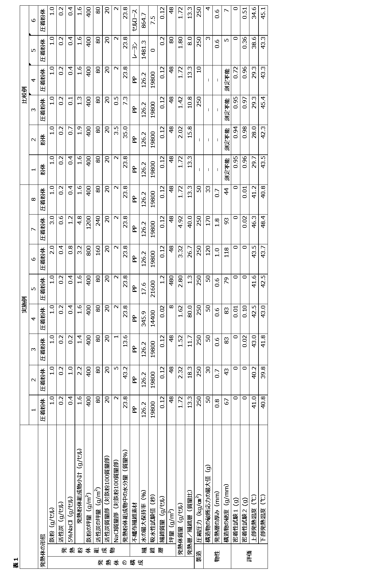
表1にも示されるように、各実施例においては、構造物として特定の硬度を有する発熱体を備えているため、この発熱層全域にわたり、発熱温度の偏りが生じることが抑制された。
これに対し、比較例1~6においては、発熱層中で発熱粉体に偏りが生じており、発熱温度の偏りが観察された。
これに対し、比較例1~6においては、発熱層中で発熱粉体に偏りが生じており、発熱温度の偏りが観察された。
この出願は、2015年2月6日に出願された日本出願特願2015-022720号を基礎とする優先権を主張し、その開示の全てをここに取り込む。
Claims (9)
- 被酸化性金属、吸水剤及び水を含む発熱層と、
水の最大保持率が500%以下である繊維層と、
を含有する構造物を備え、
前記発熱層中の水の含有量は、10質量%以上60質量%以下であり、
前記構造物の、以下の条件で測定される硬度が10g/mm以上200g/mm以下である、発熱体。
(条件)
前記構造物を一辺2cmの正方形の面を有するように切り出した試験片と、内径1cmの円筒管を用意し、前記正方形の面の中心部と、前記円筒管の中央部とが重なるようにして、前記円筒管上に前記試験片を配置する。
続いて、1mm径の円柱形状のプランジャーを用い、前記試験片の上部から前記円筒管の内側中心に前記プランジャーの先端を5cm/minの速度で下降させ、破断試験を行う。
この破断試験にて、前記試験片が破断するまでの破断応力の最大値を検出し、これをa[g]とする。
このaを前記発熱層の平均厚みb[mm]で除することで、前記硬度を求める。 - 前記繊維層は、JIS L1907(滴下法)に準じて測定される吸水性試験値が10000秒以上を示すものである、請求項1に記載の発熱体。
- 前記構造物は、前記発熱層と前記繊維層とが互いに接するように積層されてなるものである、請求項1または2に記載の発熱体。
- 前記構造物において、前記発熱層と前記繊維層との界面に、前記被酸化性金属、前記吸水剤及び前記繊維層を構成する繊維材が複合された複合領域を有する、請求項3に記載の発熱体。
- 前記発熱層の平均厚みが0.1mm以上2mm以下である、請求項1ないし4のいずれか一項に記載の発熱体。
- 被酸化性金属、吸水剤及び水を含む発熱層と、
水の最大保持率が500%以下である繊維層と、
を含有する構造物を備える発熱体の製造方法であって、
前記繊維層を準備する工程と、
被酸化性金属、吸水剤、及び水を含む発熱粉体組成物を準備する工程と、
前記繊維層の上部に、前記発熱粉体組成物を含む層を形成し、前記繊維層と前記発熱粉体組成物との積層体を得る工程と、
前記積層体を圧縮し、前記繊維層の上部に、固定化された前記発熱層を形成する工程と、
を含み、
前記発熱層中の水の含有量は、10質量%以上60質量%以下である、発熱体の製造方法。 - 前記構造物の、以下の条件で測定される硬度が10g/mm以上200g/mm以下である、請求項6に記載の発熱体の製造方法。
(条件)
前記構造物を一辺2cmの正方形の面を有するように切り出した試験片と、内径1cmの円筒管を用意し、前記正方形の面の中心部と、前記円筒管の中央部とが重なるようにして、前記円筒管上に前記試験片を配置する。
続いて、1mm径の円柱形状のプランジャーを用い、前記試験片の上部から前記円筒管の内側中心に前記プランジャーの先端を5cm/minの速度で下降させ、破断試験を行う。
この破断試験にて、前記試験片が破断するまでの破断応力の最大値を検出し、これをa[g]とする。
このaを前記発熱層の平均厚みb[mm]で除することで、前記硬度を求める。 - 前記発熱層を形成する前記工程は、前記積層体に50kg/cm2以上600kg/cm2以下の圧力で圧縮することにより行われる、請求項6または7に記載の発熱体の製造方法。
- 請求項1ないし5のいずれか一項に記載の発熱体を備える、温熱具。
Priority Applications (2)
| Application Number | Priority Date | Filing Date | Title |
|---|---|---|---|
| JP2016573360A JP6404370B2 (ja) | 2015-02-06 | 2016-02-01 | 発熱体 |
| CN201680008838.2A CN107205842B (zh) | 2015-02-06 | 2016-02-01 | 发热体 |
Applications Claiming Priority (2)
| Application Number | Priority Date | Filing Date | Title |
|---|---|---|---|
| JP2015-022720 | 2015-02-06 | ||
| JP2015022720 | 2015-02-06 |
Publications (1)
| Publication Number | Publication Date |
|---|---|
| WO2016125759A1 true WO2016125759A1 (ja) | 2016-08-11 |
Family
ID=56564101
Family Applications (1)
| Application Number | Title | Priority Date | Filing Date |
|---|---|---|---|
| PCT/JP2016/052964 Ceased WO2016125759A1 (ja) | 2015-02-06 | 2016-02-01 | 発熱体 |
Country Status (4)
| Country | Link |
|---|---|
| JP (1) | JP6404370B2 (ja) |
| CN (1) | CN107205842B (ja) |
| TW (1) | TWI700490B (ja) |
| WO (1) | WO2016125759A1 (ja) |
Citations (3)
| Publication number | Priority date | Publication date | Assignee | Title |
|---|---|---|---|---|
| JPH08127532A (ja) * | 1994-10-31 | 1996-05-21 | Takeshi Atai | 温熱貼付剤 |
| JPH08319477A (ja) * | 1995-05-27 | 1996-12-03 | Akio Usui | 発熱体組成物の発熱反応制御方法、発熱体組成物、発熱体、貼付剤、香料放散装置、殺虫剤放散装置又は殺菌剤放散装置 |
| JP2013146555A (ja) * | 2011-12-21 | 2013-08-01 | Kao Corp | 発熱体、及びこれを備えた温熱具 |
Family Cites Families (7)
| Publication number | Priority date | Publication date | Assignee | Title |
|---|---|---|---|---|
| JPH10127679A (ja) * | 1996-10-31 | 1998-05-19 | Mitsubishi Paper Mills Ltd | シート状発熱体 |
| CN1738883A (zh) * | 2002-12-27 | 2006-02-22 | 麦考尔制造株式会社 | 发热组合物和发热体 |
| US8256412B2 (en) * | 2003-07-31 | 2012-09-04 | Kao Corporation | Warming tool in a sheet form |
| CN101161219A (zh) * | 2006-10-13 | 2008-04-16 | 日本派欧尼株式会社 | 发热体和发热体的制造方法 |
| WO2011158919A1 (ja) * | 2010-06-18 | 2011-12-22 | 花王株式会社 | 発熱具 |
| CN202035164U (zh) * | 2011-04-06 | 2011-11-09 | 陈平洋 | 一种发热体 |
| CN202818642U (zh) * | 2012-07-06 | 2013-03-20 | 广东美的环境电器制造有限公司 | 一种发热体 |
-
2016
- 2016-02-01 CN CN201680008838.2A patent/CN107205842B/zh active Active
- 2016-02-01 WO PCT/JP2016/052964 patent/WO2016125759A1/ja not_active Ceased
- 2016-02-01 JP JP2016573360A patent/JP6404370B2/ja active Active
- 2016-02-04 TW TW105103814A patent/TWI700490B/zh active
Patent Citations (3)
| Publication number | Priority date | Publication date | Assignee | Title |
|---|---|---|---|---|
| JPH08127532A (ja) * | 1994-10-31 | 1996-05-21 | Takeshi Atai | 温熱貼付剤 |
| JPH08319477A (ja) * | 1995-05-27 | 1996-12-03 | Akio Usui | 発熱体組成物の発熱反応制御方法、発熱体組成物、発熱体、貼付剤、香料放散装置、殺虫剤放散装置又は殺菌剤放散装置 |
| JP2013146555A (ja) * | 2011-12-21 | 2013-08-01 | Kao Corp | 発熱体、及びこれを備えた温熱具 |
Also Published As
| Publication number | Publication date |
|---|---|
| TW201638573A (zh) | 2016-11-01 |
| CN107205842A (zh) | 2017-09-26 |
| JPWO2016125759A1 (ja) | 2017-08-24 |
| CN107205842B (zh) | 2020-08-28 |
| TWI700490B (zh) | 2020-08-01 |
| JP6404370B2 (ja) | 2018-10-10 |
Similar Documents
| Publication | Publication Date | Title |
|---|---|---|
| JP5296257B2 (ja) | 発熱体、及びこれを備えた温熱具 | |
| JP5296256B2 (ja) | 蒸気温熱具 | |
| WO2018185843A1 (ja) | 温熱具 | |
| JP6095364B2 (ja) | 温熱具 | |
| WO2017061459A1 (ja) | 水蒸気発生体および温熱具 | |
| JP2024015206A (ja) | 水蒸気発生体及び温熱具 | |
| JP2025019276A (ja) | 温熱具 | |
| JP6472917B2 (ja) | 発熱組成物及び発熱体 | |
| WO2019039497A1 (ja) | 温熱具 | |
| JP6404370B2 (ja) | 発熱体 | |
| JP6715104B2 (ja) | 温熱具 | |
| WO2017014271A1 (ja) | 温熱具 | |
| JP5886028B2 (ja) | 温熱具 | |
| JP2017170114A (ja) | 温熱具 | |
| JP2018015290A (ja) | 温熱具 | |
| JP5840554B2 (ja) | 温熱具 | |
| JP2015101719A (ja) | 発熱組成物 | |
| TWI871956B (zh) | 溫熱器具 |
Legal Events
| Date | Code | Title | Description |
|---|---|---|---|
| 121 | Ep: the epo has been informed by wipo that ep was designated in this application |
Ref document number: 16746590 Country of ref document: EP Kind code of ref document: A1 |
|
| ENP | Entry into the national phase |
Ref document number: 2016573360 Country of ref document: JP Kind code of ref document: A |
|
| NENP | Non-entry into the national phase |
Ref country code: DE |
|
| 122 | Ep: pct application non-entry in european phase |
Ref document number: 16746590 Country of ref document: EP Kind code of ref document: A1 |