WO2016125567A1 - Synchronous machine control device and permanent magnet temperature estimation method for synchronous machine - Google Patents
Synchronous machine control device and permanent magnet temperature estimation method for synchronous machine Download PDFInfo
- Publication number
- WO2016125567A1 WO2016125567A1 PCT/JP2016/051231 JP2016051231W WO2016125567A1 WO 2016125567 A1 WO2016125567 A1 WO 2016125567A1 JP 2016051231 W JP2016051231 W JP 2016051231W WO 2016125567 A1 WO2016125567 A1 WO 2016125567A1
- Authority
- WO
- WIPO (PCT)
- Prior art keywords
- temperature
- permanent magnet
- synchronous machine
- stress
- magnetic flux
- Prior art date
Links
Images


Classifications
-
- H—ELECTRICITY
- H02—GENERATION; CONVERSION OR DISTRIBUTION OF ELECTRIC POWER
- H02P—CONTROL OR REGULATION OF ELECTRIC MOTORS, ELECTRIC GENERATORS OR DYNAMO-ELECTRIC CONVERTERS; CONTROLLING TRANSFORMERS, REACTORS OR CHOKE COILS
- H02P29/00—Arrangements for regulating or controlling electric motors, appropriate for both AC and DC motors
- H02P29/60—Controlling or determining the temperature of the motor or of the drive
- H02P29/66—Controlling or determining the temperature of the rotor
- H02P29/662—Controlling or determining the temperature of the rotor the rotor having permanent magnets
-
- H—ELECTRICITY
- H02—GENERATION; CONVERSION OR DISTRIBUTION OF ELECTRIC POWER
- H02P—CONTROL OR REGULATION OF ELECTRIC MOTORS, ELECTRIC GENERATORS OR DYNAMO-ELECTRIC CONVERTERS; CONTROLLING TRANSFORMERS, REACTORS OR CHOKE COILS
- H02P21/00—Arrangements or methods for the control of electric machines by vector control, e.g. by control of field orientation
-
- H—ELECTRICITY
- H02—GENERATION; CONVERSION OR DISTRIBUTION OF ELECTRIC POWER
- H02P—CONTROL OR REGULATION OF ELECTRIC MOTORS, ELECTRIC GENERATORS OR DYNAMO-ELECTRIC CONVERTERS; CONTROLLING TRANSFORMERS, REACTORS OR CHOKE COILS
- H02P6/00—Arrangements for controlling synchronous motors or other dynamo-electric motors using electronic commutation dependent on the rotor position; Electronic commutators therefor
- H02P6/14—Electronic commutators
- H02P6/16—Circuit arrangements for detecting position
-
- H—ELECTRICITY
- H02—GENERATION; CONVERSION OR DISTRIBUTION OF ELECTRIC POWER
- H02P—CONTROL OR REGULATION OF ELECTRIC MOTORS, ELECTRIC GENERATORS OR DYNAMO-ELECTRIC CONVERTERS; CONTROLLING TRANSFORMERS, REACTORS OR CHOKE COILS
- H02P27/00—Arrangements or methods for the control of AC motors characterised by the kind of supply voltage
- H02P27/04—Arrangements or methods for the control of AC motors characterised by the kind of supply voltage using variable-frequency supply voltage, e.g. inverter or converter supply voltage
Definitions
- the present invention relates to a synchronous machine control device, which is a synchronous machine control device having a permanent magnet as a field, and a method of estimating the permanent magnet temperature of the synchronous machine.
- Step ST1 The rotational speed and current / voltage are measured.
- Step ST3 The temperature of the winding is estimated based on the measured values of the rotational speed and current / voltage.
- Step ST4 The resistance of the winding is estimated based on the estimated value of the winding temperature.
- Step ST5 Estimate the temperature of the rotor magnet unit based on the estimated value of the winding temperature.
- Step ST6 A normal value of the induced voltage is estimated based on the estimated value of the winding temperature.
- Step ST7 Estimate the actual value of the induced voltage based on the estimated value of the winding resistance.
- Step ST8 The normal value of the induced voltage coefficient estimated in step ST6 and step ST7 is compared with the actual value, and it is determined that demagnetization has occurred when the difference exceeds a predetermined threshold.
- the prior art has the following problems.
- the demagnetization detection method of the permanent magnet motor disclosed in Patent Document 1 the ratio between the temperature rise of the armature winding and the temperature rise of the rotor permanent magnet is obtained in advance by experiment, and the temperature of the armature winding is determined. Is used to estimate the temperature of the permanent magnet.
- the thermal time constant differs greatly between the armature winding and the permanent magnet, and other factors such as motor operating conditions and cooling performance also affect the temperature rise. For this reason, it is difficult to uniquely determine the temperature rise of the rotor permanent magnet with respect to the temperature rise of the armature winding, and the magnet temperature is accurately estimated based on the temperature of the armature winding for various conditions. There was a problem that it was not easy to do.
- the conventional device shown in Patent Document 2 estimates the magnet temperature in a non-energized state separated from the load. Therefore, the conventional device according to Patent Document 2 has a problem that it is difficult to estimate the magnet temperature in an energized (loaded) state in which the magnet temperature is likely to rise.
- the present invention has been made in order to solve the above-described problems. While driving a synchronous machine having a permanent magnet as a magnetic field, a current that changes without directly attaching a temperature detector to the permanent magnet ( It is an object of the present invention to obtain a synchronous machine control device and a synchronous magnet permanent magnet temperature estimation method capable of estimating the temperature of a permanent magnet with high accuracy under a load) condition.
- a synchronous machine control device includes a synchronous machine having a permanent magnet as a field, a stress estimator that estimates stress applied to the permanent magnet, and an armature linkage magnetic flux based on the stress estimated by the stress estimator.
- the armature linkage flux is calculated based on the rotor position of the synchronous machine, the current command and voltage command used for drive control of the synchronous machine, and the stress demagnetization amount of the armature linkage flux.
- a first magnet temperature estimator for outputting a corrected permanent magnet temperature estimated value in consideration of the stress demagnetization of the armature linkage flux from the estimated armature linkage flux.
- the permanent magnet temperature estimation method for a synchronous machine is a permanent magnet temperature estimation method for a synchronous machine having a permanent magnet as a field, and includes a first step for estimating a stress applied to the permanent magnet, A second step of calculating a stress demagnetization amount of the armature linkage flux based on the stress estimated by the step, a rotor position of the synchronous machine, a current command and a voltage command used for driving control of the synchronous machine, and an electric machine Estimate armature flux linkage based on the stress demagnetization of the interlinkage flux, and estimate the corrected permanent magnet temperature from the estimated armature linkage flux considering the stress demagnetization of the armature linkage flux And a third step of outputting a value.
- the stress demagnetization component is calculated based on the estimated value of the stress applied to the permanent magnet, and the temperature of the permanent magnet estimated based on the estimated value of the armature linkage flux is calculated as the stress demagnetization component. It corrects in consideration and has the composition which obtains the permanent magnet temperature estimate after amendment. As a result, demagnetization due to temperature change of the permanent magnet can be separated from demagnetization due to stress applied to the permanent magnet, and a temperature detector is directly attached to the permanent magnet while driving a synchronous machine having a permanent magnet as a field magnet. In addition, a synchronous machine control device and a synchronous magnet permanent magnet temperature estimation method capable of estimating the temperature of the permanent magnet with high accuracy under changing current (load) conditions can be obtained.
- FIG. 1 shows the hardware constitutions of the drive system which drives the synchronous machine control apparatus which concerns on Embodiment 1 of this invention. It is a whole block diagram of the synchronous machine control apparatus which concerns on Embodiment 1 of this invention. It is a whole block diagram different from FIG. 2 of the synchronous machine control apparatus which concerns on Embodiment 1 of this invention. It is a block diagram which shows an example of the magnet temperature estimator in the synchronous machine control apparatus which concerns on Embodiment 1 of this invention. It is a conceptual diagram of the 1st magnetic flux map which comprises the magnet temperature estimator which concerns on Embodiment 1 of this invention.
- Embodiment 1 of this invention it is a figure which shows an example of the demagnetizing ratio of d-axis magnetic flux (PHI) d with respect to the magnet temperature rise 10 degreeC on the conditions of the electric currents Id and Iq on several dq axes.
- PHI demagnetizing ratio of d-axis magnetic flux
- It is a conceptual diagram of the 2nd magnetic flux map which comprises the magnet temperature estimator which concerns on Embodiment 1 of this invention.
- FIG. 1 is a diagram showing a hardware configuration of a drive system that drives the synchronous machine control device according to Embodiment 1 of the present invention.
- the drive system includes a higher-level system 200 and a power source 23 in addition to the synchronous machine control device 100.
- the synchronous machine control device 100 includes a permanent magnet synchronous machine 1, a power converter 2, a current detector 3, a position detector 4, a processor 101, and a storage device 102 as hardware.
- the storage device 102 includes a volatile storage device such as a random access memory and a nonvolatile auxiliary storage device such as a flash memory.
- the storage device 102 may include a volatile storage device such as a random access memory and an auxiliary storage device such as a hard disk instead of the nonvolatile auxiliary storage device.
- the processor 101 executes the program input from the storage device 102. Since the storage device 102 includes an auxiliary storage device and a volatile storage device, a program is input to the processor 101 from the auxiliary storage device via the volatile storage device. Further, the processor 101 may output data such as a calculation result to the volatile storage device of the storage device 102, or may store the data in the auxiliary storage device via the volatile storage device.
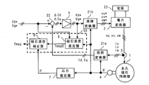
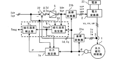
- FIG. 2 is an overall configuration diagram of the synchronous machine control device according to Embodiment 1 of the present invention.
- the synchronous machine control device includes a permanent magnet synchronous machine 1, a power converter 2, a current detector 3, a position detector 4, a current controller 5, a magnet temperature estimator 6, a stress estimator 7, a magnet temperature corrector 8, and coordinates.
- Converters 21a and 21b and an adder / subtractor 22 are provided.
- a combination of the magnet temperature estimator 6 and the magnet temperature corrector 8 is referred to as a magnet temperature calculator 50.
- the synchronous machine control device according to the first embodiment assumes that a current command on a current command coordinate or a torque command is given from a higher-level system from a higher-level system not shown in FIG.
- the current command coordinate is a rotation orthogonal biaxial coordinate (dq axis), which will be described later, and in the following description, the current command coordinate is abbreviated as “on dq axis”,
- the current command for each axis corresponds to Id * and Iq *.
- the host system when the present invention is applied to an electric vehicle (EV), a hybrid vehicle vehicle including both an internal combustion engine and a motor, or an electric vehicle such as a railway vehicle.
- EV electric vehicle
- hybrid vehicle vehicle including both an internal combustion engine and a motor
- electric vehicle such as a railway vehicle.
- notch accelerator
- brake input amount
- vehicle speed vehicle speed
- various input amounts from a driver operator
- FA factory automation
- elevator applications there is a host system that generates a current command based on various factors in factory automation (FA) and elevator applications.
- FA factory automation
- the estimated temperature value Tmag of the permanent magnet that forms the field of the synchronous machine 1 estimated by the synchronous machine control device of the present invention is transmitted to a higher system, and this estimated temperature value is used to control the higher system. May be used.
- the host system that provides the current command is not limited, and therefore, the description of the host system is limited to the above-described example.
- the current controller 5, magnet temperature estimator 6, stress estimator 7, magnet temperature corrector 8, coordinate converters 21 a and 21 b, and adder / subtractor 22 shown in FIG. 2 are processors that execute programs stored in the storage device 102. 101 or a processing circuit such as a system LSI (not shown).
- a plurality of processors 101 and a plurality of storage devices 102 may execute the above functions in cooperation, or a plurality of processing circuits may execute the above functions in cooperation. Further, the above functions may be executed in cooperation with a combination of a plurality of processors 101 and a plurality of storage devices 102 and a plurality of processing circuits.
- the synchronous machine 1 in Embodiment 1 shown in FIG. 2 has a permanent magnet as a field magnet.
- a permanent magnet as a field magnet.
- the power converter 2 converts the power supplied from the power supply 23 into multiphase AC power and outputs a multiphase AC voltage. More specifically, the power converter 2 is connected to the armature winding of the synchronous machine 1 and performs a conversion operation including a known PWM (pulse width modulation) inverter.
- PWM pulse width modulation
- the coordinate converter 21b uses the voltage command obtained from the current controller 5 (strictly, the voltage command output from the current controller 5) based on the rotor position ⁇ of the synchronous machine 1 obtained by the position detector 4. The coordinate conversion is performed to generate a multiphase AC voltage command. Then, the power converter 2 outputs a multiphase voltage to the synchronous machine 1 based on the multiphase AC voltage command generated by the coordinate converter 21b, and drives the synchronous machine 1.
- an output current is generated in the armature winding of the synchronous machine 1.
- the output current generated in the armature winding is hereinafter referred to as an armature current.
- the power source 23 of the first embodiment includes a power source that outputs a DC voltage, a battery such as a battery, or a power source that obtains a DC voltage from a single-phase or three-phase AC power source using a known converter. 23.
- the armature current that is the output current of the synchronous machine 1 is detected by a current detector 3 including a current sensor.
- the current detector 3 detects an armature current of all phases among the three-phase armature currents iu, iv, iw of the synchronous machine 1, or
- the position detector 4 in FIG. 2 shows an example in which the rotor position ⁇ of the synchronous machine 1 is detected using a known resolver, encoder, or the like.
- the position detector 4 is not limited to this configuration, and may be configured to estimate the rotor position ⁇ by calculation using a voltage command, an armature current, or the like by applying a known adaptive observer or the like. It is.
- the rotor position ⁇ of the synchronous machine 1 generally indicates an angle in the N-pole direction of the permanent magnet with respect to the axis taken with reference to the u-phase armature winding.
- the rotation orthogonal biaxial coordinates that rotate at the rotational speed of the synchronous machine 1 are defined as dq axes, and as usual, the d axis is in the N pole direction of the permanent magnet, that is, the field.
- the magnetic flux direction is defined, and the q axis is defined as an orthogonal direction advanced by 90 ° with respect to the d axis. The following description also follows the definition of this coordinate axis.
- FIG. 3 is an overall configuration diagram different from FIG. 2 of the synchronous machine control device according to Embodiment 1 of the present invention.
- the synchronous machine control device shown in FIG. 3 includes a position detector 4a that obtains the rotor position ⁇ by estimation calculation instead of the position detector 4 in FIG. Since the configuration of the position detector 4a can be realized by the configuration shown in Patent Documents 3 and 4, for example, the details are omitted.
- FIG. 2 and FIG. 3 are only the portion related to the position detectors 4 and 4a, and the other configurations are the same.
- the coordinate converter 21a converts the armature currents iu, iv, iw of the synchronous machine 1 into currents Id, Iq on the dq axis based on the rotor position ⁇ by the calculation of the following equation (1). .
- the current controller 5 outputs the voltage commands Vd * and Vq * on the dq axis so that the currents Id and Iq on the dq axis match the desired current commands Id * and Iq *. Specifically, the current controller 5 calculates the proportionality of the following equation (2) based on the deviation between the current commands Id * and Iq * on the dq axis and the currents Id and Iq on the dq axis. Integration control (PI control) is performed to generate voltage commands (current feedback control commands) Vd * and Vq * on the dq axes.
- PI control voltage commands
- Kpd is a current control d-axis proportional gain
- Kid is a current control d-axis integral gain
- Kpq is a current control q-axis proportional gain
- Kiq is a current control q-axis integral gain
- s is a Laplace operator. I mean. The reciprocal 1 / s of the Laplace operator s means one time integration.
- the current controller 5 calculates a voltage feedforward term using motor parameters such as an inductance value and a resistance value and the rotational speed ⁇ , and applies a known voltage non-interference control that is added to the current feedback control command.
- the voltage commands Vd * and Vq * on the dq axes may be obtained.
- the current controller 5 In order to perform the voltage feedforward control, the current controller 5 needs to obtain a rotational speed ⁇ that is not described as an input to the current controller 5 in FIG. 2 (FIG. 3). In this case, the current controller 5 can obtain the rotational speed ⁇ by performing a differentiation operation on the rotor position ⁇ detected by the position detector 4 (or 4a).
- the voltage commands Vd * and Vq * on the dq axes output from the current controller 5 are converted into voltage commands vu * and vu * based on the rotor position ⁇ by the following equation (3) in the coordinate converter 21b. After being converted into vv * and vw *, it is output to the power converter 2.
- the power converter 2 outputs the voltages vu, vv, and vw to the synchronous machine 1 by a known PWM (pulse width modulation) method or the like based on the voltage commands vu *, vv *, and vw *.
- PWM pulse width modulation
- the magnet temperature estimator 6, the stress estimator 7, and the magnet temperature corrector 8, which are necessary for estimating the temperature of the permanent magnet that forms the field of the synchronous machine 1, will be described.
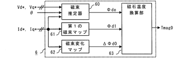
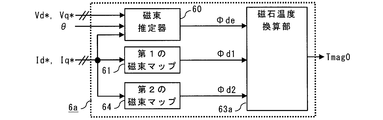
- FIG. 4 is a configuration diagram showing an example of the magnet temperature estimator 6 in the synchronous machine control device according to Embodiment 1 of the present invention.
- the magnet temperature estimator 6 according to the first embodiment includes a magnetic flux estimator 60, a first magnetic flux map 61, a magnetic flux change map 62, and a magnet temperature conversion unit 63. .
- the magnet temperature conversion unit 63 calculates the d-axis magnetic flux estimated value ⁇ de estimated by the magnetic flux estimator 60 and the first magnetic flux map when the synchronous machine 1 is driven with the current commands Id * and Iq * on the dq axes. Based on 61 and the magnetic flux change map 62, the permanent magnet temperature estimated value Tmag0 of the synchronous machine 1 before correction is output.
- Tmag0 is the estimated permanent magnet temperature value of the synchronous machine 1 "before correction"
- Tmag0 is corrected by a stress estimator 7 and a magnet temperature corrector 8, which will be described later, which are one of the features of the synchronous machine control apparatus according to Embodiment 1 of the present invention, and the corrected synchronous machine 1 is corrected.
- Tmag is obtained and the accuracy of the permanent magnet temperature estimated value of the synchronous machine 1 is improved.
- the magnetic flux estimator 60 calculates the rotational speed ⁇ calculated based on the rotor position ⁇ detected by the position detector 4 (or 4a), the voltage commands Vd *, Vq *, and dq on the dq axes. Based on the current commands Id * and Iq * (currents Id and Iq on the dq axis may be used instead of Id * and Iq *), a state quantity related to the armature linkage magnetic flux ⁇ is estimated.
- the armature interlinkage magnetic flux ⁇ refers to a combined magnetic flux of the permanent magnet magnetic flux ⁇ m and the magnetic flux (armature reaction magnetic flux) ⁇ a generated by the armature current.
- ⁇ d and ⁇ q are obtained by calculation of the following expression (4), which is a relational expression with the q-axis component ⁇ q (hereinafter referred to as q-axis magnetic flux) of the armature linkage magnetic flux ⁇ .
- Ld is an inductance in the d-axis direction (hereinafter referred to as d-axis inductance)
- Lq is an inductance in the q-axis direction (hereinafter referred to as q-axis inductance)
- R is a resistance.
- the resistance R is mainly the resistance of the armature winding of the synchronous machine 1, and when the influence of the wiring resistance between the synchronous machine 1 and the power converter 2 is so large that it cannot be ignored, this wiring resistance is also The resistance value is considered.
- Laplace operator s means one time derivative, but the derivative term need not be considered in the steady state.
- the magnetic flux estimator 60 uses the voltage commands Vd * and Vq * on the dq axes instead of the voltages Vd and Vq on the dq axes, and calculates the electric machine by the following equation (6).
- the d-axis component ⁇ de of the estimated value ⁇ e of the interlinkage flux ⁇ e (hereinafter referred to as an estimated value of the d-axis flux)
- the q-axis component ⁇ qe of the estimated value ⁇ e of the armature linkage flux ⁇ (hereinafter, the estimated value of the q-axis flux) (Notation).
- the magnetic flux estimator 60 obtains the absolute value
- a predetermined permanent magnet magnetic flux value ( ⁇ m0) is given as an initial value of ⁇ de at the start of driving of the synchronous machine 1.
- the rotor position ⁇ detected by the position detector 4 (or 4a) is included in the input to the magnetic flux estimator 60 in FIG. This assumes that the process of obtaining the rotational speed ⁇ by performing the differential operation using the rotor position ⁇ is included in the process of the magnetic flux estimator 60. Therefore, if the processing for obtaining the rotational speed ⁇ is performed by another component, it is not always necessary to include the rotor position ⁇ as an input of the magnetic flux estimator 60.
- the term including the Laplace operator s in the above equation (4) may be ignored on the assumption that the change in current is gradual.
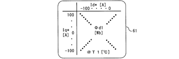
- FIG. 5 is a conceptual diagram of a first magnetic flux map 61 constituting the magnet temperature estimator according to Embodiment 1 of the present invention.
- This first magnetic flux map 61 shows that the permanent magnet of the synchronous machine 1 has a temperature T1 in the entire range of the current commands Id * and Iq * on the dq axes necessary for driving the synchronous machine 1 in the entire operation region.
- the correlation between the current commands Id * and Iq * on the dq axis and the d-axis component of the armature flux linkage ⁇ (referred to as ⁇ d1) in the state of It is obtained and mapped using.
- mapping instead of the current commands Id * and Iq *, association with the currents Id and Iq on the dq axis may be performed, and the same applies to the following mapping.
- the current commands Id * and Iq * on the dq axes can be obtained by using the d-axis component ⁇ d1 of the armature linkage flux ⁇ under the condition that the permanent magnet of the synchronous machine 1 is at the temperature T1. Converted to
- the conversion value is estimated using linear interpolation or approximation based on the first magnetic flux map 61.
- a value can be output.
- an estimated value can be output by using the same method.
- FIG. 6 is a conceptual diagram of the magnetic flux change map 62 constituting the magnet temperature estimator according to Embodiment 1 of the present invention.
- This magnetic flux change map 62 shows the current command Id * on the dq axis in the entire range of the current command Id *, Iq * on the dq axis necessary for driving the synchronous machine 1 in the entire operation region.
- the current commands Id * and Iq * on the dq axes are the armatures when the permanent magnet of the synchronous machine 1 changes by ⁇ T0 from the temperature T1 to the temperature T2 different from the temperature T1.
- the amount of change ⁇ d0 of the d-axis component of the linkage flux ⁇ is converted.
- the temperatures T1 and T2 are preferably set to the upper and lower limits of the temperature change range of the permanent magnet that can be changed by driving the synchronous machine 1 (forming the field of the synchronous machine 1). In the present invention, the magnitude relationship between the temperatures T1 and T2 does not matter.
- the magnet temperature conversion unit 63 calculates the d-axis magnetic flux estimated value ⁇ de at the temperature T1 estimated by the magnetic flux estimator 60 when the synchronous machine 1 is driven with the current commands Id * and Iq * on the dq axes. From the d-axis component ⁇ d1 of the armature linkage flux ⁇ obtained from the first magnetic flux map 61 and the change amount ⁇ d0 of the d-axis component of the armature linkage flux ⁇ obtained from the flux change map 62, Based on Expression (8), the permanent magnet temperature estimated value Tmag0 of the synchronous machine 1 before correction is generated.
- the magnet temperature estimator 6 allows the permanent machine 1 before correction when the synchronous machine 1 is driven with the current commands Id * and Iq * on the dq axes.
- An estimated magnet temperature value Tmag0 can be obtained.
- the magnet temperature estimator 6 uses the absolute value
- the first magnetic flux map 61a is used for the synchronous machine in the entire range of the current commands Id * and Iq * on the dq axes necessary for driving the synchronous machine 1 in the entire operation region.
- ) when the permanent magnet of 1 is at the temperature T1 is experimentally known or known. Obtain and map using a magnetic field analysis tool.
- the current commands Id * and Iq * on the dq axes can be obtained by calculating the absolute value of the armature linkage magnetic flux ⁇ under the condition that the permanent magnet of the synchronous machine 1 is at the temperature T1. Converted to ⁇ 1
- the magnetic flux change map 62a is on the dq axis in the entire range of the current commands Id * and Iq * on the dq axis necessary for driving the synchronous machine 1 in the entire operation region.
- the current commands Id * and Iq * are constant
- ) is obtained and mapped using an actual experimental experiment or a known magnetic field analysis tool.
- the current commands Id * and Iq * on the dq axes can be obtained by changing the armature interlinkage magnetic flux ⁇ when the permanent magnet of the synchronous machine 1 is changed by ⁇ T0 from the temperature T1 to the temperature T2.
- the magnet temperature estimator 6 estimates the armature flux linkage estimated by the magnetic flux estimator 60 when the synchronous machine 1 is driven by the current commands Id * and Iq * on the dq axes.
- the permanent magnet temperature estimated value Tmag0 of the synchronous machine 1 before correction can be obtained from the change amount
- the correlation between the permanent magnet magnetic flux ⁇ m, that is, the d-axis magnetic flux ⁇ d and the temperature Tm of the permanent magnet differs depending on the magnetic saturation state of the synchronous machine 1 that changes depending on the magnitude of the armature current.
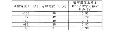
- FIG. 7 is a diagram showing an example of a demagnetization ratio of the d-axis magnetic flux ⁇ d with respect to a magnet temperature increase of 10 ° C. under the conditions of a plurality of currents Id and Iq on the dq axes in the first embodiment of the present invention. is there.
- the permanent magnet magnetic flux ⁇ m changes due to the temperature change of the permanent magnet, and the magnetic saturation state slightly changes. For this reason, even when the currents Id and Iq on the dq axis are constant, if the temperature of the permanent magnet changes, the values of the d axis inductance Ld and the q axis inductance Lq also change.
- both the d-axis inductance Ld and the permanent magnet magnetic flux ⁇ m are changed.
- the magnitude of the change of the d-axis inductance Ld and the permanent magnet magnetic flux ⁇ m with respect to the magnet temperature change is dq-axis. It differs depending on the currents Id and Iq (that is, load conditions).
- the magnet temperature estimator 6 in the first embodiment includes the magnetic flux estimator 60, the first magnetic flux map 61, the magnetic flux change map 62, and the magnet temperature conversion unit 63. Then, when the synchronous machine 1 is driven by the current commands Id * and Iq * on the dq axes, the magnet temperature estimator 6 calculates the d-axis magnetic flux estimated value ⁇ de estimated by the magnetic flux estimator 60 and the first Based on the magnetic flux map 61 and the magnetic flux change map 62, the permanent magnet temperature estimated value Tmag0 of the synchronous machine 1 before correction is output.
- the magnetic flux change with respect to the magnet temperature change is Appears on the d-axis side. For this reason, the sensitivity of the magnetic flux change with respect to the magnet temperature change can be improved, and the temperature estimation accuracy of the permanent magnet is improved.
- FIG. 8 is a block diagram showing an example of the magnet temperature estimator 6a in the synchronous machine control device according to Embodiment 1 of the present invention.
- the magnet temperature estimator 6a according to the first embodiment includes a magnetic flux estimator 60, a first magnetic flux map 61, a second magnetic flux map 64, and a magnet temperature conversion unit 63a. ing.
- the magnet temperature conversion unit 63a when the synchronous machine 1 is driven by the current commands Id * and Iq * on the dq axes, and the d-axis magnetic flux estimated value ⁇ de estimated by the magnetic flux estimator 60, and the first magnetic flux map. Based on 61 and the second magnetic flux map 64, the permanent magnet temperature estimated value Tmag0 of the synchronous machine 1 before correction is output.
- the first magnetic flux map 61 has the same configuration as that shown in FIG.
- the correlation between the temperature Tm of the permanent magnet and the d-axis magnetic flux ⁇ d under various current Id and Iq conditions is obtained from the two correlation information “the correlation with the component (referred to as ⁇ d2)”. This is different from the magnet temperature estimator 6 having the configuration shown in FIG.
- FIG. 9 is a conceptual diagram of the second magnetic flux map 64 constituting the magnet temperature estimator 6a according to Embodiment 1 of the present invention.
- the second magnetic flux map 64 shows that the permanent magnet of the synchronous machine 1 has a temperature T2 in the entire range of the current commands Id * and Iq * on the dq axes necessary for driving the synchronous machine 1 in the entire operation region.
- the correlation between the current commands Id * and Iq * on the dq axis and the d-axis component ⁇ d2 of the armature flux linkage ⁇ in the state of the above is obtained and mapped using actual experimental experiments or a well-known magnetic field analysis tool It is a thing.
- the current commands Id * and Iq * on the dq axes can be obtained by using the d-axis component ⁇ d2 of the armature linkage flux ⁇ when the permanent magnet of the synchronous machine 1 is at the temperature T2. Converted to
- the permanent magnet temperature estimated value Tmag0 of the synchronous machine 1 before correction is generated.
- the magnet temperature estimator 6a allows the permanent machine 1 before correction when the synchronous machine 1 is driven with the current commands Id * and Iq * on the dq axes.
- An estimated magnet temperature value Tmag0 can be obtained.
- the permanent magnet temperature of the synchronous machine 1 before correction is obtained by using the absolute value
- the estimated value Tmag0 can be obtained.
- a magnetic flux map showing a correlation between the current commands Id * and Iq * on the dq axes and the d-axis component of the armature linkage magnetic flux ⁇ under a temperature condition different from the temperatures T1 and T2 is provided. It is good also as a simple structure. Needless to say, if the temperature condition for obtaining the magnetic flux map increases, the accuracy of estimating the permanent magnet temperature of the synchronous machine 1 is improved. However, if the number of maps becomes large, a large amount of labor is required to create the maps, so the number of maps is kept to the minimum necessary.
- the magnet temperature estimator 6 takes into account that the correlation between the d-axis magnetic flux ⁇ d and the temperature Tm of the permanent magnet varies depending on the magnetic saturation state of the synchronous machine 1. In consideration of the armature current dependency of the change in the d-axis magnetic flux ⁇ d with respect to the magnet temperature change, the permanent magnet temperature estimated value Tmag0 of the synchronous machine 1 before correction is output.
- the stress estimator 7 and the magnet temperature corrector 8 are provided. Then, the magnet temperature corrector 8 converts the permanent magnet temperature estimated value Tmag0 of the synchronous machine 1 before correction estimated by the magnet temperature estimator 6 (or 6a) into a permanent magnet estimated by the stress estimator 7. Based on the stress, a stress demagnetization component is calculated, and the stress demagnetization component is converted into a temperature correction amount and corrected.
- FIG. 10 is a contour diagram showing the stress distribution in the structural analysis result when the rotor 30 of the synchronous machine 1 having the permanent magnet 31 according to the first embodiment of the present invention is rotating at a certain rotational speed.
- the rotor 30 of the synchronous machine 1 rotates, stress is generated in the permanent magnet 31 by centrifugal force.
- the rotor 30 is a partial model in order to shorten the analysis time.
- the permanent magnet 31 is held in the slot 32 of the rotor 30 and deformed into a bow shape by centrifugal force. As a result, tensile stress is generated on the outer peripheral side, and compressive stress is generated on the inner peripheral side.
- FIG. 11 is a diagram showing the rate of change of the magnetic flux density Br with respect to the applied compressive stress as an experimental result when the compressive stress is applied to the permanent magnet in Embodiment 1 of the present invention.
- the rate of change of the magnetic flux density Br decreases as the stress increases. That is, when stress is applied to the permanent magnet, demagnetization occurs.
- the demagnetization is about 0.2%.
- FIG. 12 is a block diagram showing an example of the stress estimator 7 for the permanent magnet 31 in the synchronous machine control device according to Embodiment 1 of the present invention.
- the stress estimator 7 shown in FIG. 12 calculates the rotational speed ⁇ from the rotor position ⁇ of the synchronous machine 1 detected by the position detector 4 (or 4a) by the first stress estimator 70, and performs structural analysis.
- the stress value ⁇ applied to the permanent magnet is estimated by referring to the structural analysis data 71 which is the relationship between the obtained stress generated in the permanent magnet 31 and the rotational speed ⁇ .
- the structural analysis data 71 can be a calculation formula representing the relationship between the rotational speed and the stress obtained from the structural analysis shown in FIG. 10, or a map of stress values corresponding to each rotational speed.
- FIG. 13 is a configuration diagram showing an example of the magnet temperature corrector 8 in the synchronous machine control device according to Embodiment 1 of the present invention.
- a magnet temperature corrector 8 shown in FIG. 13 includes a magnetic flux estimation unit 80 and a magnet temperature conversion unit 81.
- the magnetic flux estimation unit 80 derives the change amount ⁇ de of the armature interlinkage magnetic flux due to the stress demagnetization from the relationship between the stress ⁇ obtained by the permanent magnet pressurization experiment and the residual magnetization Br. Then, the magnet temperature conversion unit 81 converts the change amount ⁇ de of the armature interlinkage magnetic flux due to the stress demagnetization into a temperature correction amount, corrects the permanent magnet temperature estimated value Tmag0, and corrects the corrected permanent magnet temperature estimated value Tmag. Is output.
- the output permanent magnet temperature estimated value Tmag may be transmitted to an upper system not described in the first embodiment, and this estimated value may be used for controlling the upper system.
- this estimated value may be used for controlling the upper system.
- an example in which the permanent magnet temperature estimated value Tmag is fed back to the host system and the current command on the dq axis is corrected will be described in a fourth embodiment to be described later, and the permanent magnet temperature estimated value Tmag is An example of using this to limit the torque command will be described in a fifth embodiment to be described later.
- the above is the description of the synchronous machine control device according to the first embodiment.
- the magnet temperature is estimated while accurately grasping the change in the armature linkage magnetic flux with respect to the change in the magnet temperature that varies depending on the current command (magnetic saturation state of the synchronous machine). Yes. Accordingly, there is an effect that the temperature of the permanent magnet can be accurately estimated under any current (load) condition without directly attaching the temperature detector to the permanent magnet.
- the demagnetization generated by the stress applied to the permanent magnet which may cause a temperature estimation error, is corrected so that the thermal demagnetization due to the temperature change of the permanent magnet and the demagnetization due to the stress applied to the permanent magnet can be separated. Thereby, the effect which the magnet temperature estimation precision improves is also acquired.
- FIG. 14 is an overall configuration diagram of a synchronous machine control device according to Embodiment 2 of the present invention.
- the synchronous machine control device uses a magnet temperature estimator 6 for the stress estimator 7 of the synchronous machine control device according to the first embodiment shown in FIG. 2.
- the stress estimator 7a is configured to take the estimated temperature Tmag0 of the permanent magnet and the current commands Id * and Iq * as inputs.
- FIG. 15 is a block diagram showing an example of the stress estimator 7a of the permanent magnet 31 in the synchronous machine control device according to Embodiment 2 of the present invention.
- the stress estimator 7a calculates the rotational speed ⁇ from the rotor position ⁇ of the synchronous machine 1 and estimates the stress ⁇ 1 applied to the permanent magnet from the result of the structural analysis.
- a second stress estimation unit 72 for estimating the stress ⁇ 2 applied to the permanent magnet based on the temperature Tmag0 of the permanent magnet estimated by the magnet temperature estimator 6, and a torque applied to the permanent magnet from the torque generated by the current command
- a third stress estimation unit 73 for estimating the stress ⁇ 3 and a magnet stress calculation unit 74 for calculating the stress ⁇ applied to the permanent magnet by adding the outputs ⁇ 1 to ⁇ 3 from the respective stress estimation units.
- the second embodiment when estimating the stress applied to the permanent magnet, not only the stress estimated from the rotational speed of the rotor of the synchronous machine, but also the dimensional change caused by the temperature change of the permanent magnet.
- the thermal stress caused by the torque and the stress caused by the torque generated by the drive current are also taken into consideration. As a result, it is possible to further improve the accuracy of estimating the stress applied to the permanent magnet.
- FIG. 16 is an overall configuration diagram of a synchronous machine control device according to Embodiment 3 of the present invention.
- the synchronous machine control device inputs the permanent magnet temperature estimated value Tmag corrected by the magnet temperature corrector 8 to the stress estimator 7 b, so that the temperature of the permanent magnet A stress ⁇ (thermal stress) generated due to a dimensional change accompanying the change is estimated.
- the magnet temperature corrector 8 performs recursive temperature correction by correcting the permanent magnet temperature Tmag0 before correction using the stress ⁇ . Since the operations relating to the other configurations are the same as those in FIG. 2 of the first embodiment, the same reference numerals are given and the description thereof is omitted.
- the stress estimator 7b changes the dimensional stress based on the linear expansion coefficient of the material. Estimated by considering structural analysis. The above is the description of the synchronous machine control device according to the third embodiment.
- the third embodiment when estimating the permanent magnet temperature, it is possible to separate the thermal demagnetization due to the temperature change of the permanent magnet and the demagnetization due to the thermal stress related to the temperature dependence on the permanent magnet. As described above, the demagnetization amount generated by the stress applied to the permanent magnet that may cause a temperature estimation error is corrected. As a result, it is possible to improve the temperature estimation accuracy of the permanent magnet.
- the stress ⁇ thermal stress generated by the dimensional change accompanying the temperature change of the permanent magnet is estimated, and the temperature correction of the permanent magnet is performed recursively. As a result, more accurate temperature estimation is possible.
- FIG. 17 is an overall configuration diagram of a synchronous machine control device according to Embodiment 4 of the present invention.
- the synchronous machine control device has a current that corrects the current command on the dq axis in accordance with the estimated permanent magnet temperature Tmag corrected by the magnet temperature corrector 8.
- the command corrector 9 is further provided.
- the current command before correction on the input side of the current command corrector 9 is Id0 *, Iq0 *, and the corrected current command on the output side of the current command corrector 9
- the current command is Id * and Iq *.
- One of the purposes for estimating the temperature Tm of the permanent magnet of the synchronous machine 1 is to correct the torque change due to demagnetization.
- the current commands Id * and Iq * are corrected within the allowable temperature range where irreversible demagnetization does not occur, the torque output of the synchronous machine 1 is adjusted, and the torque change is corrected. It is configured.
- the torque ⁇ output from the synchronous machine 1 is calculated by the following equation (11).
- Pm is the number of pole pairs of the synchronous machine 1.
- the current command corrector 9 adjusts the current commands Id * and Iq * so as to compensate for the torque change based on the permanent magnet temperature estimated value Tmag.
- the current command is corrected when the temperature of the permanent magnet forming the field of the synchronous machine rises. As a result, it is possible to correct a torque change due to thermal demagnetization and improve torque accuracy.
- FIG. 18 is an overall configuration diagram of a synchronous machine control device according to Embodiment 5 of the present invention.
- the synchronous machine control device has a torque command limit that limits the torque command to the synchronous machine 1 according to the permanent magnet temperature estimated value Tmag corrected by the magnet temperature corrector 8. And a current command generator 11 that generates a current command based on the limited torque command.
- the torque command before limitation on the input side of the torque command limiter 10 is ⁇ 0 *
- the torque command after limitation on the output side of the torque command limiter 10 is ⁇ *. .
- the torque command limiter 10 limits the torque command for the synchronous machine 1 according to the corrected permanent magnet temperature estimated value Tmag, and decreases the armature current (effective value). It is set as the structure which suppresses the further temperature rise.
- the torque command limiter 10 limits the torque command ⁇ 0 * before the limit in the host system as shown in the first embodiment according to the corrected permanent magnet temperature estimated value Tmag, and the torque after the limit Output as command ⁇ *.
- the correlation between the estimated permanent magnet temperature value Tmag and the torque command limit value is set according to the driving conditions such as the rotation speed of the synchronous machine 1, which is related to the iron loss, the heat capacity of the synchronous machine 1, and the cooling performance.
- the torque command limiter 10 determines that the permanent magnet temperature has gradually approached the temperature leading to irreversible demagnetization, and lowers the torque command.
- the torque command limiter 10 performs a process such as “0” and then outputs a torque command ⁇ * after limitation.
- the torque command limiter 10 may be configured to gradually decrease the torque command limit value as the permanent magnet temperature estimated value Tmag increases.
- the current command generator 11 in FIG. 18 generates the current commands Id * and Iq * on the dq axes, which are control commands, based on the torque command after the limit ⁇ *.
- the current command generator 11 generates an appropriate current command Id * on the dq axis that matches a desired condition (for example, maximum efficiency condition, minimum current condition, etc.) with respect to the limited torque command ⁇ *.
- Iq * may be output.
- the current commands Id * and Iq * should be selected so that the current for the same torque is minimized. Is more suitable.
- the optimum values of the current commands Id * and Iq * on the dq axes corresponding to various torques of the synchronous machine 1 are measured and mapped in advance, and the torque command ⁇ * after limitation is set during operation. May be referred to from time to time to obtain current commands Id * and Iq * on the dq axes according to ⁇ *.
- the above is the description of the synchronous machine control device according to the fifth embodiment.
- the torque command is limited when the temperature of the permanent magnet forming the field of the synchronous machine rises.
- the armature current effective value
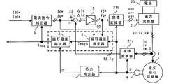
- FIG. 19 is an overall configuration diagram of a synchronous machine control device according to Embodiment 6 of the present invention.
- the synchronous machine control device inputs the stress ⁇ applied to the permanent magnet estimated by the stress estimator 7 to the magnet temperature estimator 6b, so that the temperature of the permanent magnet Estimate Tmag. That is, the magnet temperature estimator 6b has the functions of both the magnet temperature estimator 6 and the magnet temperature corrector 8 shown in FIG. 2 in the first embodiment, and the magnet temperature calculator 50 combining these two functions. Play the same role.
- FIG. 20 is a block diagram showing an example of a magnet temperature estimator 6b in the synchronous machine control device according to Embodiment 6 of the present invention.
- the magnet temperature estimator 6b includes a magnetic flux estimator 60a, a first magnetic flux map 61, a magnetic flux change map 62, and a magnet temperature conversion unit 63. Then, when the synchronous machine 1 is driven by the current commands Id * and Iq * on the dq axes, the magnet temperature conversion unit 63 calculates the d-axis magnetic flux estimated value ⁇ de estimated by the magnetic flux estimator 60a and the first Based on the magnetic flux map 61 and the magnetic flux change map 62, the permanent magnet temperature estimated value Tmag of the synchronous machine 1 is output.
- the magnetic flux estimator 60a calculates the rotational speed ⁇ calculated based on the rotor position ⁇ detected by the position detector 4, the voltage commands Vd * and Vq * on the dq axes, and the current command Id on the dq axes. *, Iq * (currents Id and Iq on the dq axis may be used instead of Id * and Iq *), and the stress ⁇ applied to the permanent magnet estimated by the stress estimator 7
- the state quantity related to the armature flux linkage ⁇ is estimated.
- the magnet temperature corrector 8 has a magnetic flux estimation unit 80, and stress reduction is performed with respect to the permanent magnet temperature Tmag 0 estimated in consideration of thermal demagnetization. The correction based on the change amount ⁇ de of the armature interlinkage magnetic flux due to the magnetism was performed.
- the magnetic flux estimator 60a in the magnet temperature estimator 6b directly takes the d-axis magnetic flux estimated value ⁇ de into consideration in consideration of stress demagnetization. presume.
- FIG. 21 is a block diagram showing an example of a magnet temperature estimator 6c in the synchronous machine control device according to Embodiment 6 of the present invention.
- the magnet temperature estimator 6c includes a magnetic flux estimator 60a, a first magnetic flux map 61, a second magnetic flux map 64, and a magnet temperature conversion unit 63a. Then, when the synchronous machine 1 is driven by the current commands Id * and Iq * on the dq axes, the magnet temperature conversion unit 63a uses the d-axis magnetic flux estimated value ⁇ de estimated by the magnetic flux estimator 60a and the first Based on the magnetic flux map 61 and the second magnetic flux map 64, the permanent magnet temperature estimated value Tmag of the synchronous machine 1 before correction is output.
- the stress demagnetization generated due to the stress applied to the permanent magnet is also taken into consideration, so that the magnet temperature estimation accuracy is improved.
- the position detector 4a described in FIG. 3 of the first embodiment may be used to estimate and calculate the rotor position ⁇ . .
- the magnet temperature estimators 6b and 6c and the magnet temperature calculator 50 correspond to the first magnet temperature estimator, and the magnet temperature estimators 6 and 6a are the second magnet temperature estimators. It corresponds to an estimator.
Abstract
Description
ステップST1:回転速度および電流・電圧を測定する。
ステップST3:回転速度および電流・電圧の前記測定値に基づいて、巻線の温度を推定する。
ステップST4:巻線温度の推定値に基づいて、巻線の抵抗を推定する。
ステップST5:巻線温度の推定値に基づいて、回転子磁石部の温度を推定する。
ステップST6:巻線温度の推定値に基づいて、誘起電圧の正常値を推定する。
ステップST7:巻線抵抗の推定値に基づいて、誘起電圧の実際の値を推定する。
ステップST8:ステップST6およびステップST7において推定した誘起電圧係数の正常値と実際の値を比較して、その差が所定の閾値を超えているときに減磁が生じていると判断する。 As an example of a synchronous machine control device that solves such a problem, there is a conventional device that sequentially performs the following steps to determine the demagnetization state of the rotor magnet unit (for example, a patent) Reference 1).
Step ST1: The rotational speed and current / voltage are measured.
Step ST3: The temperature of the winding is estimated based on the measured values of the rotational speed and current / voltage.
Step ST4: The resistance of the winding is estimated based on the estimated value of the winding temperature.
Step ST5: Estimate the temperature of the rotor magnet unit based on the estimated value of the winding temperature.
Step ST6: A normal value of the induced voltage is estimated based on the estimated value of the winding temperature.
Step ST7: Estimate the actual value of the induced voltage based on the estimated value of the winding resistance.
Step ST8: The normal value of the induced voltage coefficient estimated in step ST6 and step ST7 is compared with the actual value, and it is determined that demagnetization has occurred when the difference exceeds a predetermined threshold.
・負荷から切り離されて無通電状態で回転する状態の回転子の回転数を検出する。
・検出された回転数に基づいて、回転子の磁石温度を推定する。
・推定された磁石温度に基づいて、同期機(永久磁石電動機)に対する電流指令を補正するための補正量を求め、補正量に基づいて同期機を駆動する。 As another example of a similar control device, there is a conventional device that estimates the temperature of the permanent magnet from the sum of the rotational speed, iron loss, and mechanical loss by performing the following control (for example, , See Patent Document 2).
・ Detects the rotational speed of the rotor that is disconnected from the load and rotates in a non-energized state.
-Estimate the magnet temperature of the rotor based on the detected rotational speed.
A correction amount for correcting the current command to the synchronous machine (permanent magnet motor) is obtained based on the estimated magnet temperature, and the synchronous machine is driven based on the correction amount.
特許文献1に示された永久磁石電動機の減磁検出方法においては、電機子巻線の温度上昇と回転子永久磁石の温度上昇との比をあらかじめ実験により求めておき、電機子巻線の温度に基づいて永久磁石の温度を推定している。 However, the prior art has the following problems.
In the demagnetization detection method of the permanent magnet motor disclosed in
図1は、本発明の実施の形態1に係る同期機制御装置を駆動する駆動システムのハードウエア構成を示す図である。図1において、この駆動システムは、同期機制御装置100に加えてさらに上位のシステム200、および電源23を備える。同期機制御装置100は、ハードウエアとして、永久磁石同期機1、電力変換器2、電流検出器3、位置検出器4、プロセッサ101、および記憶装置102を備える。
FIG. 1 is a diagram showing a hardware configuration of a drive system that drives the synchronous machine control device according to


具体的には、永久磁石温度推定値Tmagを上位のシステムにフィードバックし、d-q軸上の電流指令を補正する例を、後述の実施の形態4で説明し、永久磁石温度推定値Tmagを用いてトルク指令に制限をかける例を、後述の実施の形態5で説明する。以上が、実施の形態1における同期機制御装置の説明である。 The output permanent magnet temperature estimated value Tmag may be transmitted to an upper system not described in the first embodiment, and this estimated value may be used for controlling the upper system.
Specifically, an example in which the permanent magnet temperature estimated value Tmag is fed back to the host system and the current command on the dq axis is corrected will be described in a fourth embodiment to be described later, and the permanent magnet temperature estimated value Tmag is An example of using this to limit the torque command will be described in a fifth embodiment to be described later. The above is the description of the synchronous machine control device according to the first embodiment.
次に、本発明の実施の形態2に係る同期機制御装置について説明する。
図14は、本発明の実施の形態2に係る同期機制御装置の全体構成図である。
Next, a synchronous machine control device according to
FIG. 14 is an overall configuration diagram of a synchronous machine control device according to
次に、本発明の実施の形態3に係る同期機制御装置について説明する。
図16は、本発明の実施の形態3に係る同期機制御装置の全体構成図である。
Next, a synchronous machine control device according to
FIG. 16 is an overall configuration diagram of a synchronous machine control device according to
次に、本発明の実施の形態4に係る同期機制御装置について説明する。
図17は、本発明の実施の形態4に係る同期機制御装置の全体構成図である。
Next, a synchronous machine control device according to
FIG. 17 is an overall configuration diagram of a synchronous machine control device according to
次に、本発明の実施の形態5に係る同期機制御装置について説明する。
図18は、本発明の実施の形態5に係る同期機制御装置の全体構成図である。
Next, a synchronous machine control device according to
FIG. 18 is an overall configuration diagram of a synchronous machine control device according to
次に、本発明の実施の形態6に係る同期機制御装置について説明する。
図19は、本発明の実施の形態6に係る同期機制御装置の全体構成図である。
Next, a synchronous machine control device according to
FIG. 19 is an overall configuration diagram of a synchronous machine control device according to
Claims (14)
- 界磁として永久磁石を有する同期機と、
前記永久磁石にかかる応力を推定する応力推定器と、
前記応力推定器により推定された前記応力に基づいて電機子鎖交磁束の応力減磁分を演算し、前記同期機の回転子位置、前記同期機の駆動制御に用いられる電流指令と電圧指令、および前記電機子鎖交磁束の応力減磁分に基づいて、電機子鎖交磁束を推定し、推定した前記電機子鎖交磁束から前記電機子鎖交磁束の応力減磁分を考慮した補正後の永久磁石温度推定値を出力する第1磁石温度推定器と
を備える同期機制御装置。 A synchronous machine having a permanent magnet as a field,
A stress estimator for estimating a stress applied to the permanent magnet;
Based on the stress estimated by the stress estimator, the stress demagnetization component of the armature linkage magnetic flux is calculated, the rotor position of the synchronous machine, the current command and the voltage command used for the drive control of the synchronous machine, Based on the stress demagnetization amount of the armature linkage magnetic flux, the armature linkage flux is estimated, and after the correction considering the stress demagnetization amount of the armature linkage flux from the estimated armature linkage flux A synchronous machine control device comprising: a first magnet temperature estimator that outputs a permanent magnet temperature estimated value of - 前記第1磁石温度推定器は、
前記同期機の回転子位置、および前記同期機の駆動制御に用いられる電流指令と電圧指令に基づいて、電機子鎖交磁束を推定し、推定した前記電機子鎖交磁束から前記同期機の前記永久磁石の温度を推定する第2磁石温度推定器と、
前記応力推定器により推定された前記永久磁石にかかる応力に基づいて電機子鎖交磁束の応力減磁分を演算し、前記電機子鎖交磁束の応力減磁分を温度補正量に換算し、前記第2磁石温度推定器により推定された前記永久磁石の温度に対して前記温度補正量による補正を施し、前記補正後の永久磁石温度推定値を出力する磁石温度補正器と
を有する請求項1に記載の同期機制御装置。 The first magnet temperature estimator is
Based on the rotor position of the synchronous machine and the current command and voltage command used for driving control of the synchronous machine, the armature linkage magnetic flux is estimated, and the estimated armature linkage magnetic flux is used to estimate the armature linkage flux. A second magnet temperature estimator for estimating the temperature of the permanent magnet;
Based on the stress applied to the permanent magnet estimated by the stress estimator, the stress demagnetization amount of the armature linkage magnetic flux is calculated, the stress demagnetization amount of the armature linkage flux is converted into a temperature correction amount, The magnet temperature corrector which correct | amends by the said temperature correction amount with respect to the temperature of the said permanent magnet estimated by the said 2nd magnet temperature estimator, and outputs the permanent magnet temperature estimated value after the correction | amendment. A synchronous machine control device according to claim 1. - 前記第2磁石温度推定器は、
前記永久磁石の温度が第1の温度の条件下における、前記電流指令と、前記電機子鎖交磁束との相関である第1の磁束マップと、
前記永久磁石の温度が第1の温度から第2の温度まで変化した時の、前記電流指令と、前記電機子鎖交磁束の変化量との相関である磁束変化マップと
をあらかじめ記憶しておき、前記第1の磁束マップおよび前記磁束変化マップを用いて、推定した前記電機子鎖交磁束に応じた前記永久磁石の温度を推定する
請求項2に記載の同期機制御装置。 The second magnet temperature estimator is
A first magnetic flux map that is a correlation between the current command and the armature interlinkage magnetic flux under a condition where the temperature of the permanent magnet is a first temperature;
A magnetic flux change map that is a correlation between the current command and the amount of change in the armature flux linkage when the temperature of the permanent magnet changes from the first temperature to the second temperature is stored in advance. The synchronous machine control device according to claim 2, wherein the temperature of the permanent magnet according to the estimated armature flux linkage is estimated using the first magnetic flux map and the magnetic flux change map. - 前記第2磁石温度推定器は、
前記永久磁石の温度が第1の温度の条件下における、前記電流指令と、前記電機子鎖交磁束との相関である第1の磁束マップと、
前記永久磁石の温度が第2の温度の条件下における、前記電流指令と、前記電機子鎖交磁束との相関である第2の磁束マップと
をあらかじめ記憶しておき、前記第1の磁束マップおよび前記第2の磁束マップを用いて、推定した前記電機子鎖交磁束に応じた前記永久磁石の温度を推定する
請求項2に記載の同期機制御装置。 The second magnet temperature estimator is
A first magnetic flux map that is a correlation between the current command and the armature interlinkage magnetic flux under a condition where the temperature of the permanent magnet is a first temperature;
Under the condition that the temperature of the permanent magnet is a second temperature, the current command and a second magnetic flux map that is a correlation between the armature linkage magnetic fluxes are stored in advance, and the first magnetic flux map is stored. The synchronous machine control device according to claim 2, wherein the temperature of the permanent magnet according to the estimated armature flux linkage is estimated using the second magnetic flux map. - 前記応力推定器は、前記同期機の前記回転子位置に基づいて前記同期機の回転速度を算出し、算出した前記回転速度に基づいて前記永久磁石にかかる応力を推定する
請求項2から4のいずれか1項に記載の同期機制御装置。 5. The stress estimator calculates a rotation speed of the synchronous machine based on the rotor position of the synchronous machine, and estimates a stress applied to the permanent magnet based on the calculated rotation speed. The synchronous machine control device according to any one of claims. - 前記応力推定器は、
前記同期機の前記回転子位置に基づいて前記同期機の回転速度を算出し、算出した前記回転速度に基づいて前記永久磁石にかかる応力を第1の応力として推定し、
前記第2磁石温度推定器により推定された前記永久磁石の温度に基づいて永久磁石にかかる応力を第2の応力として推定し、
前記電流指令により発生するトルクから前記永久磁石にかかる応力を第3の応力として推定し、
前記第1の応力、前記第2の応力、前記第3の応力を合算することで前記永久磁石にかかる応力を推定する
請求項2から4のいずれか1項に記載の同期機制御装置。 The stress estimator is
Calculating a rotational speed of the synchronous machine based on the rotor position of the synchronous machine, estimating a stress applied to the permanent magnet based on the calculated rotational speed as a first stress,
Estimating the stress applied to the permanent magnet as the second stress based on the temperature of the permanent magnet estimated by the second magnet temperature estimator;
A stress applied to the permanent magnet is estimated as a third stress from the torque generated by the current command,
The synchronous machine control device according to any one of claims 2 to 4, wherein the stress applied to the permanent magnet is estimated by adding the first stress, the second stress, and the third stress. - 前記応力推定器は、前記磁石温度補正器により補正された前記補正後の永久磁石温度推定値に基づいて前記永久磁石にかかる応力を推定する
請求項2から4のいずれか1項に記載の同期機制御装置。 The synchronization according to any one of claims 2 to 4, wherein the stress estimator estimates a stress applied to the permanent magnet based on the corrected permanent magnet temperature estimated value corrected by the magnet temperature corrector. Machine control device. - 前記磁石温度補正器により補正された前記補正後の永久磁石温度推定値に応じて前記電流指令を補正する電流指令補正器
をさらに備える請求項2から7のいずれか1項に記載の同期機制御装置。 The synchronous machine control according to any one of claims 2 to 7, further comprising: a current command corrector that corrects the current command in accordance with the corrected permanent magnet temperature estimated value corrected by the magnet temperature corrector. apparatus. - 前記磁石温度補正器により補正された前記補正後の永久磁石温度推定値に応じて前記同期機に対するトルク指令を制限するトルク指令制限器と、
前記トルク指令制限器によって制限された前記トルク指令に基づいて前記電流指令を生成する電流指令生成器と
をさらに備える請求項2から8のいずれか1項に記載の同期機制御装置。 A torque command limiter that limits a torque command to the synchronous machine according to the corrected permanent magnet temperature estimated value corrected by the magnet temperature corrector;
The synchronous machine control device according to any one of claims 2 to 8, further comprising: a current command generator that generates the current command based on the torque command limited by the torque command limiter. - 前記第1磁石温度推定器は、
前記永久磁石の温度が第1の温度の条件下における、前記電流指令と、前記電機子鎖交磁束との相関である第1の磁束マップと、
前記永久磁石の温度が第1の温度から第2の温度まで変化した時の、前記電流指令と、前記電機子鎖交磁束の変化量との相関である磁束変化マップと
をあらかじめ記憶しておき、前記第1の磁束マップおよび前記磁束変化マップを用いて、推定した前記電機子鎖交磁束に応じた前記補正後の永久磁石温度推定値を出力する
請求項1に記載の同期機制御装置。 The first magnet temperature estimator is
A first magnetic flux map that is a correlation between the current command and the armature interlinkage magnetic flux under a condition where the temperature of the permanent magnet is a first temperature;
A magnetic flux change map that is a correlation between the current command and the amount of change in the armature flux linkage when the temperature of the permanent magnet changes from the first temperature to the second temperature is stored in advance. The synchronous machine control device according to claim 1, wherein the corrected permanent magnet temperature estimated value corresponding to the estimated armature flux linkage is output using the first magnetic flux map and the magnetic flux change map. - 前記第1磁石温度推定器は、
前記永久磁石の温度が第1の温度の条件下における、前記電流指令と、前記電機子鎖交磁束との相関である第1の磁束マップと、
前記永久磁石の温度が第2の温度の条件下における、前記電流指令と、前記電機子鎖交磁束との相関である第2の磁束マップと
をあらかじめ記憶しておき、前記第1の磁束マップおよび前記第2の磁束マップを用いて、推定した前記電機子鎖交磁束に応じた前記補正後の永久磁石温度推定値を出力する
請求項1に記載の同期機制御装置。 The first magnet temperature estimator is
A first magnetic flux map that is a correlation between the current command and the armature interlinkage magnetic flux under a condition where the temperature of the permanent magnet is a first temperature;
Under the condition that the temperature of the permanent magnet is a second temperature, the current command and a second magnetic flux map that is a correlation between the armature linkage magnetic fluxes are stored in advance, and the first magnetic flux map is stored. The synchronous machine control device according to claim 1, wherein the corrected permanent magnet temperature estimated value corresponding to the estimated armature flux linkage is output using the second magnetic flux map. - 前記応力推定器は、前記同期機の前記回転子位置に基づいて前記同期機の回転速度を算出し、算出した前記回転速度に基づいて前記永久磁石にかかる応力を推定する
請求項1、10、11のいずれか1項に記載の同期機制御装置。 The stress estimator calculates a rotation speed of the synchronous machine based on the rotor position of the synchronous machine, and estimates a stress applied to the permanent magnet based on the calculated rotation speed. The synchronous machine control device according to any one of 11. - 界磁として永久磁石を有する同期機の永久磁石温度推定方法であって、
前記永久磁石にかかる応力を推定する第1ステップと、
前記第1ステップにより推定された前記応力に基づいて電機子鎖交磁束の応力減磁分を演算する第2ステップと、
前記同期機の回転子位置、前記同期機の駆動制御に用いられる電流指令と電圧指令、および前記電機子鎖交磁束の応力減磁分に基づいて、電機子鎖交磁束を推定し、推定した前記電機子鎖交磁束から前記電機子鎖交磁束の応力減磁分を考慮した補正後の永久磁石温度推定値を出力する第3ステップと
を有する同期機の永久磁石温度推定方法。 A method for estimating a permanent magnet temperature of a synchronous machine having a permanent magnet as a field,
A first step of estimating a stress applied to the permanent magnet;
A second step of calculating a stress demagnetization amount of the armature flux linkage based on the stress estimated in the first step;
Based on the rotor position of the synchronous machine, the current command and voltage command used for drive control of the synchronous machine, and the stress demagnetization amount of the armature linkage magnetic flux, the armature linkage flux is estimated and estimated. And a third step of outputting a corrected permanent magnet temperature estimated value in consideration of a stress demagnetization amount of the armature linkage flux from the armature linkage flux. - 前記第3ステップは、前記同期機の回転子位置、および前記同期機の駆動制御に用いられる電流指令と電圧指令に基づいて、電機子鎖交磁束を推定する第4ステップと、
前記第4ステップにより推定された前記電機子鎖交磁束から前記同期機の永久磁石温度を推定する第5ステップと、
前記第2ステップにより演算された前記電機子鎖交磁束の応力減磁分を温度補正量に換算し、前記第5ステップにより推定された前記永久磁石温度に対して前記温度補正量による補正を施し、前記補正後の永久磁石温度推定値を出力する第6ステップと
を有する請求項13に記載の同期機の永久磁石温度推定方法。 The third step is a fourth step of estimating an armature linkage flux based on a rotor position of the synchronous machine and a current command and a voltage command used for driving control of the synchronous machine;
A fifth step of estimating a permanent magnet temperature of the synchronous machine from the armature flux linkage estimated by the fourth step;
The stress demagnetization amount of the armature flux linkage calculated in the second step is converted into a temperature correction amount, and the permanent magnet temperature estimated in the fifth step is corrected by the temperature correction amount. A method for estimating a permanent magnet temperature of a synchronous machine according to claim 13, further comprising: a sixth step of outputting the corrected permanent magnet temperature estimated value.
Priority Applications (2)
| Application Number | Priority Date | Filing Date | Title |
|---|---|---|---|
| US15/547,546 US10418929B2 (en) | 2015-02-02 | 2016-01-18 | Synchronous machine control device and permanent magnet temperature estimation method for synchronous machine |
| JP2016573261A JP6218976B2 (en) | 2015-02-02 | 2016-01-18 | Synchronous machine control device and permanent magnet temperature estimation method for synchronous machine |
Applications Claiming Priority (2)
| Application Number | Priority Date | Filing Date | Title |
|---|---|---|---|
| JP2015018277 | 2015-02-02 | ||
| JP2015-018277 | 2015-02-02 |
Publications (1)
| Publication Number | Publication Date |
|---|---|
| WO2016125567A1 true WO2016125567A1 (en) | 2016-08-11 |
Family
ID=56563918
Family Applications (1)
| Application Number | Title | Priority Date | Filing Date |
|---|---|---|---|
| PCT/JP2016/051231 WO2016125567A1 (en) | 2015-02-02 | 2016-01-18 | Synchronous machine control device and permanent magnet temperature estimation method for synchronous machine |
Country Status (3)
| Country | Link |
|---|---|
| US (1) | US10418929B2 (en) |
| JP (1) | JP6218976B2 (en) |
| WO (1) | WO2016125567A1 (en) |
Cited By (6)
| Publication number | Priority date | Publication date | Assignee | Title |
|---|---|---|---|---|
| JP2018046615A (en) * | 2016-09-13 | 2018-03-22 | 株式会社豊田中央研究所 | Temperature estimation device, interlinkage magnetic flux estimation device and motor controller |
| JP6320603B1 (en) * | 2017-06-20 | 2018-05-09 | 三菱電機株式会社 | AC rotating machine control device |
| CN111211719A (en) * | 2018-11-06 | 2020-05-29 | 株洲中车时代电气股份有限公司 | Method and system for estimating temperature of rotor magnetic steel of permanent magnet synchronous motor |
| WO2021240883A1 (en) * | 2020-05-28 | 2021-12-02 | 日立Astemo株式会社 | Motor control device and motor control method |
| WO2021245904A1 (en) * | 2020-06-05 | 2021-12-09 | 三菱電機株式会社 | Motor temperature and torque estimation device, and motor control device |
| WO2024053177A1 (en) * | 2022-09-05 | 2024-03-14 | 日立Astemo株式会社 | Motor control device |
Families Citing this family (7)
| Publication number | Priority date | Publication date | Assignee | Title |
|---|---|---|---|---|
| JP6950755B2 (en) * | 2018-01-26 | 2021-10-13 | 日産自動車株式会社 | Inverter control method and inverter control device |
| JP6980716B2 (en) * | 2019-03-29 | 2021-12-15 | 株式会社日立製作所 | Permanent magnet synchronous machine drive, permanent magnet synchronous machine torque compensation method, and electric vehicle |
| US11211851B2 (en) * | 2019-05-10 | 2021-12-28 | Rockwell Automation Technologies, Inc. | System and method for providing safe limited force producing power in a motor |
| DE102019131280A1 (en) * | 2019-11-20 | 2021-05-20 | Dr. Ing. H.C. F. Porsche Aktiengesellschaft | Method for operating an electrical machine, electrical machine, motor vehicle, method for operating a motor vehicle |
| WO2021127806A1 (en) * | 2019-12-23 | 2021-07-01 | 潍柴动力股份有限公司 | Temperature compensation method and apparatus for output torque of permanent magnet synchronous electric motor |
| KR20220049947A (en) * | 2020-10-15 | 2022-04-22 | 현대자동차주식회사 | Iron loss reduction control apparatus and method for motor permanent magnet overtemperature protection |
| CN112737426B (en) * | 2020-12-29 | 2022-10-18 | 新乡市夏烽电器有限公司 | Temperature rise model reconstruction-based deep well permanent magnet synchronous motor demagnetization prevention control method |
Citations (4)
| Publication number | Priority date | Publication date | Assignee | Title |
|---|---|---|---|---|
| JP2010011640A (en) * | 2008-06-27 | 2010-01-14 | Hitachi Ltd | Permanent magnet type rotary electric machine |
| JP2010041842A (en) * | 2008-08-06 | 2010-02-18 | Toshiba Corp | Permanent-magnet type rotary electric machine and permanent-magnet type motor drive system |
| JP2012095534A (en) * | 2012-02-16 | 2012-05-17 | Hitachi Ltd | Permanent magnet-type rotary electric machine |
| CN103051088A (en) * | 2013-01-24 | 2013-04-17 | 哈尔滨理工大学 | Axial-segmented solid permanent-magnet rotor |
Family Cites Families (6)
| Publication number | Priority date | Publication date | Assignee | Title |
|---|---|---|---|---|
| JP4672236B2 (en) | 2001-04-24 | 2011-04-20 | 三菱電機株式会社 | Control device for synchronous motor |
| JP2005192325A (en) | 2003-12-25 | 2005-07-14 | Yaskawa Electric Corp | Method for detecting demagnetization of permanent-magnet electric motor |
| BRPI0924515B1 (en) | 2009-03-26 | 2020-09-15 | Mitsubishi Electric Corporation | CONTROLLER FOR A ROTARY AC MACHINE |
| DE112013000640T5 (en) | 2012-01-20 | 2014-10-23 | Mitsubishi Electric Corporation | Control device and control method for a permanent magnet motor |
| JP5693652B2 (en) * | 2013-05-13 | 2015-04-01 | 三菱電機株式会社 | Synchronous machine controller |
| JP6277013B2 (en) * | 2014-02-21 | 2018-02-07 | 日立オートモティブシステムズ株式会社 | Actuator control device |
-
2016
- 2016-01-18 WO PCT/JP2016/051231 patent/WO2016125567A1/en active Application Filing
- 2016-01-18 US US15/547,546 patent/US10418929B2/en active Active
- 2016-01-18 JP JP2016573261A patent/JP6218976B2/en active Active
Patent Citations (4)
| Publication number | Priority date | Publication date | Assignee | Title |
|---|---|---|---|---|
| JP2010011640A (en) * | 2008-06-27 | 2010-01-14 | Hitachi Ltd | Permanent magnet type rotary electric machine |
| JP2010041842A (en) * | 2008-08-06 | 2010-02-18 | Toshiba Corp | Permanent-magnet type rotary electric machine and permanent-magnet type motor drive system |
| JP2012095534A (en) * | 2012-02-16 | 2012-05-17 | Hitachi Ltd | Permanent magnet-type rotary electric machine |
| CN103051088A (en) * | 2013-01-24 | 2013-04-17 | 哈尔滨理工大学 | Axial-segmented solid permanent-magnet rotor |
Cited By (8)
| Publication number | Priority date | Publication date | Assignee | Title |
|---|---|---|---|---|
| JP2018046615A (en) * | 2016-09-13 | 2018-03-22 | 株式会社豊田中央研究所 | Temperature estimation device, interlinkage magnetic flux estimation device and motor controller |
| JP6320603B1 (en) * | 2017-06-20 | 2018-05-09 | 三菱電機株式会社 | AC rotating machine control device |
| CN111211719A (en) * | 2018-11-06 | 2020-05-29 | 株洲中车时代电气股份有限公司 | Method and system for estimating temperature of rotor magnetic steel of permanent magnet synchronous motor |
| WO2021240883A1 (en) * | 2020-05-28 | 2021-12-02 | 日立Astemo株式会社 | Motor control device and motor control method |
| WO2021245904A1 (en) * | 2020-06-05 | 2021-12-09 | 三菱電機株式会社 | Motor temperature and torque estimation device, and motor control device |
| JPWO2021245904A1 (en) * | 2020-06-05 | 2021-12-09 | ||
| JP7341339B2 (en) | 2020-06-05 | 2023-09-08 | 三菱電機株式会社 | Motor temperature and torque estimation device and motor control device |
| WO2024053177A1 (en) * | 2022-09-05 | 2024-03-14 | 日立Astemo株式会社 | Motor control device |
Also Published As
| Publication number | Publication date |
|---|---|
| US10418929B2 (en) | 2019-09-17 |
| JPWO2016125567A1 (en) | 2017-04-27 |
| US20180269822A1 (en) | 2018-09-20 |
| JP6218976B2 (en) | 2017-10-25 |
Similar Documents
| Publication | Publication Date | Title |
|---|---|---|
| JP6218976B2 (en) | Synchronous machine control device and permanent magnet temperature estimation method for synchronous machine | |
| JP5420006B2 (en) | Synchronous machine controller | |
| JP5693652B2 (en) | Synchronous machine controller | |
| JP5357232B2 (en) | Synchronous machine controller | |
| JP6367332B2 (en) | Inverter control device and motor drive system | |
| JP5781235B2 (en) | Synchronous machine controller | |
| JP2008029082A (en) | Rotating electric machine control unit, method and program for controlling rotating electric machine | |
| JP4652176B2 (en) | Control device for permanent magnet type rotating electrical machine | |
| JP4425091B2 (en) | Motor position sensorless control circuit | |
| JP5788057B1 (en) | Synchronous machine controller | |
| KR100921115B1 (en) | Control System Of Permanent Magnet Synchronous Motor And Method Thereof | |
| JP2013078214A (en) | Controlling device of permanent magnet synchronous motor | |
| JP4053511B2 (en) | Vector controller for wound field synchronous machine | |
| JP5050387B2 (en) | Motor control device | |
| JP5726273B2 (en) | Synchronous machine control device having permanent magnet state estimation function and method thereof | |
| JP4884342B2 (en) | Induction motor control device | |
| JP2008148437A (en) | Controller for permanent magnet type synchronous motor | |
| JP6183194B2 (en) | Motor control device | |
| JP7251424B2 (en) | INVERTER DEVICE AND INVERTER DEVICE CONTROL METHOD | |
| JP5332305B2 (en) | Control device for permanent magnet type synchronous motor | |
| JP5326284B2 (en) | Control device for synchronous motor | |
| JP4127957B2 (en) | Electric motor control device | |
| JP2010200544A (en) | Ac motor controller and control method | |
| JP2010022189A (en) | Position sensorless control circuit for motor | |
| JP2009268183A (en) | Drive apparatus for three-phase ac motor |
Legal Events
| Date | Code | Title | Description |
|---|---|---|---|
| 121 | Ep: the epo has been informed by wipo that ep was designated in this application |
Ref document number: 16746398 Country of ref document: EP Kind code of ref document: A1 |
|
| ENP | Entry into the national phase |
Ref document number: 2016573261 Country of ref document: JP Kind code of ref document: A |
|
| WWE | Wipo information: entry into national phase |
Ref document number: 15547546 Country of ref document: US |
|
| NENP | Non-entry into the national phase |
Ref country code: DE |
|
| 122 | Ep: pct application non-entry in european phase |
Ref document number: 16746398 Country of ref document: EP Kind code of ref document: A1 |