WO2016121261A1 - 車両用駆動装置 - Google Patents
車両用駆動装置 Download PDFInfo
- Publication number
- WO2016121261A1 WO2016121261A1 PCT/JP2015/085418 JP2015085418W WO2016121261A1 WO 2016121261 A1 WO2016121261 A1 WO 2016121261A1 JP 2015085418 W JP2015085418 W JP 2015085418W WO 2016121261 A1 WO2016121261 A1 WO 2016121261A1
- Authority
- WO
- WIPO (PCT)
- Prior art keywords
- torque
- clutch
- engine
- stroke
- speed
- Prior art date
- Legal status (The legal status is an assumption and is not a legal conclusion. Google has not performed a legal analysis and makes no representation as to the accuracy of the status listed.)
- Ceased
Links
Images








Classifications
-
- F—MECHANICAL ENGINEERING; LIGHTING; HEATING; WEAPONS; BLASTING
- F02—COMBUSTION ENGINES; HOT-GAS OR COMBUSTION-PRODUCT ENGINE PLANTS
- F02D—CONTROLLING COMBUSTION ENGINES
- F02D29/00—Controlling engines, such controlling being peculiar to the devices driven thereby, the devices being other than parts or accessories essential to engine operation, e.g. controlling of engines by signals external thereto
-
- F—MECHANICAL ENGINEERING; LIGHTING; HEATING; WEAPONS; BLASTING
- F02—COMBUSTION ENGINES; HOT-GAS OR COMBUSTION-PRODUCT ENGINE PLANTS
- F02D—CONTROLLING COMBUSTION ENGINES
- F02D29/00—Controlling engines, such controlling being peculiar to the devices driven thereby, the devices being other than parts or accessories essential to engine operation, e.g. controlling of engines by signals external thereto
- F02D29/02—Controlling engines, such controlling being peculiar to the devices driven thereby, the devices being other than parts or accessories essential to engine operation, e.g. controlling of engines by signals external thereto peculiar to engines driving vehicles; peculiar to engines driving variable pitch propellers
-
- F—MECHANICAL ENGINEERING; LIGHTING; HEATING; WEAPONS; BLASTING
- F16—ENGINEERING ELEMENTS AND UNITS; GENERAL MEASURES FOR PRODUCING AND MAINTAINING EFFECTIVE FUNCTIONING OF MACHINES OR INSTALLATIONS; THERMAL INSULATION IN GENERAL
- F16D—COUPLINGS FOR TRANSMITTING ROTATION; CLUTCHES; BRAKES
- F16D48/00—External control of clutches
- F16D48/02—Control by fluid pressure
Definitions
- the present invention relates to a vehicle drive device including a manual transmission and a manual clutch.
- Patent Document 1 in a vehicle equipped with a manual transmission and a manual clutch, a technology that can easily start the vehicle has been proposed.
- the engine rotation speed is controlled to a target engine rotation speed higher than the idling rotation speed.
- the target engine speed is determined based on the clutch stroke.
- the present invention has been made in view of such circumstances, and suppresses generation of engine stall and engine noise when the vehicle starts in a vehicle drive device including a manual transmission and a manual clutch.
- An object of the present invention is to provide a vehicle drive device that can perform the above-described operation.
- the invention of the vehicle drive device includes an input shaft to which engine torque generated by the engine is input, and an output shaft that is rotationally connected to drive wheels of the vehicle.
- a manual transmission in which a plurality of shift stages each having a different gear ratio obtained by dividing the rotational speed of the input shaft by the rotational speed of the output shaft is provided, and provided between the engine and the input shaft,
- a clutch that makes a clutch torque that is a torque transmitted between an engine and the input shaft variable, and a stroke of a clutch operating member for variably operating the clutch torque or a clutch stroke that is a stroke of the clutch are detected.
- the clutch stroke is detected based on the clutch stroke detected by the clutch stroke detector.
- a clutch stroke speed calculation unit that calculates a clutch stroke speed that is a change amount per unit time of the stroke, the clutch stroke detected by the clutch stroke detection unit, and the clutch stroke calculated by the clutch stroke speed calculation unit Based on the speed, a target engine torque calculation unit that calculates a target engine torque at the time of start of the vehicle, and the engine torque generated by the engine at the time of start of the vehicle is calculated by the target engine torque calculation unit.
- An engine control unit that controls the engine so as to achieve the target engine torque.
- the target engine torque calculation unit calculates the target engine torque at the start of the vehicle based on the clutch stroke and the clutch stroke speed. Thereby, the target engine torque in which the torque corresponding to the clutch stroke speed is added is calculated. Therefore, when the vehicle starts, the engine response delay is offset by the torque corresponding to the increase / decrease of the clutch stroke speed before the engine response delay to the change of the clutch torque due to the operation of the clutch operation member occurs. Response delay is suppressed. As a result, a decrease and an increase in engine rotation speed due to engine response delay are suppressed, and engine stall and engine noise during vehicle start-up are suppressed.
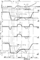
- FIG. 5 is a diagram showing a “clutch torque map” representing a relationship between a clutch stroke Stc and a clutch torque Tc. It is a time chart at the time of start of a vehicle, and is input shaft rotational speed Ni, engine rotational speed Ne, accelerator stroke Sta, clutch stroke Stc, predicted clutch stroke Stcp, clutch stroke speed Spc, correction torque Tcr, clutch torque Tc, predicted clutch torque. It is a figure showing Tcp, engine torque Te, and target engine torque Teg in time series.
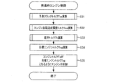
- 3 is a flowchart of “clutch / engine cooperative control” executed by a control unit shown in FIG. 1.
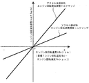
- FIG. 6 is a diagram showing a “correction torque map” that represents the relationship among clutch stroke speed Spc, engine rotation speed Ne, and correction torque Tcr.
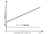
- 2 is a flowchart of “engine rotation speed adjustment torque calculation processing” executed by a control unit shown in FIG. 1. It is the figure which showed the "target engine speed map” showing the relationship between the accelerator stroke Sta and the target engine speed Net.
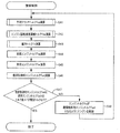
- FIG. 6 is a diagram showing an “engine rotation speed adjustment torque map” that represents a relationship between an engine differential rotation speed ⁇ Ne and an engine rotation speed adjustment torque Tea. It is a flowchart of "a maintenance torque calculation process” which the control part shown in FIG. 1 performs. It is a flowchart of "return control” performed by the control unit shown in FIG.
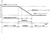
- FIG. 6 is a time chart of “return control”, and is a diagram showing a target engine torque Teg, a return control engine torque Tert, and a required engine torque Ter in a time series.
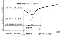
- FIG. 6 is a time chart of “return control”, and is a diagram showing a target engine torque Teg, a return control engine torque Tert, and a required engine torque Ter in a time series.
- FIG. 9 is a time chart for explaining the effect of the second embodiment, and is a diagram showing a clutch stroke Stc, a predicted clutch stroke Stcp, a clutch stroke speed Spc, an engine torque Ne, and a target engine torque Teg in time series.
- FIG. 1 A vehicle 100 equipped with a vehicle drive device 1 according to an embodiment of the present invention will be described with reference to FIG.
- thick lines indicate mechanical connections between the devices, and arrows with broken lines indicate control signal lines.
- an engine 2 a clutch 3, a manual transmission 4, and a differential 17 are provided in series in the vehicle 100 in this order.
- the differential 17 is connected to drive wheels 18R and 18L of the vehicle 100.
- Drive wheels 18R and 18L are front wheels or rear wheels, or front and rear wheels of vehicle 100.
- the vehicle 100 includes a control unit 10, an accelerator pedal 51, an accelerator stroke sensor 52, a clutch pedal 53, a clutch stroke sensor 54, and a master cylinder 55.
- the accelerator pedal 51 is for variably operating the engine torque Te generated by the engine 2.
- the accelerator stroke sensor 52 detects an accelerator stroke Sta that is a stroke of the accelerator pedal 51, and outputs the detection result to the control unit 10.
- Engine 2 is a gasoline engine, diesel engine, or the like that uses hydrocarbon fuel such as gasoline or light oil and generates engine torque Te.
- the engine 2 includes a crankshaft 21, a fuel supply device 23, an engine rotation speed sensor 24, and an oil temperature sensor 25.
- the engine 2 is provided with a throttle valve 22 and an ignition device (not shown) for igniting an air-fuel mixture in a cylinder (not shown).
- the crankshaft 21 is rotationally driven by a piston (not shown).
- the throttle valve 22 is provided in an intake manifold (not shown) communicating with the cylinder of the engine 2.
- the throttle valve 22 adjusts the amount of air (air mixture amount) drawn into the cylinder.
- the fuel supply device 23 is provided on an intake manifold or a cylinder head (not shown) of the engine 2.
- the fuel supply device 23 is a device that supplies fuel such as gasoline or light oil.
- the engine rotation speed sensor 24 detects the engine rotation speed Ne, which is the rotation speed of the crankshaft 21, and outputs the detection result to the control unit 10.
- the oil temperature sensor 25 detects the oil temperature t of the engine oil that lubricates the engine 2 and outputs the detection result to the control unit 10.
- the crankshaft 21 is rotatably connected to a generator 26 and a compressor 27a of an air conditioner 27.
- Generator 26 generates electric power necessary for vehicle 100.
- the clutch pedal 53 (clutch operating member) is for making the clutch 3 disengaged or connected and variably operating a clutch torque Tc described later.
- the master cylinder 55 generates an operating pressure corresponding to the stroke of the clutch pedal 53.
- the clutch stroke sensor 54 (clutch stroke detection unit) detects the clutch stroke Stc, which is the stroke of the clutch pedal 53, and outputs the detection result to the control unit 10.
- the clutch 3 is provided between the crankshaft 21 of the engine 2 and the input shaft 41 of the manual transmission 4.
- the clutch 3 is a manual clutch that connects or disconnects the crankshaft 21 and the input shaft 41 by the operation of the clutch pedal 53 by the driver.
- the clutch 3 can change a clutch torque Tc that is a torque transmitted between the crankshaft 21 and the input shaft 41.
- the clutch 3 includes a flywheel 31, a clutch disk 32, a clutch cover 33, a diaphragm spring 34, a pressure plate 35, a release bearing 37, and a slave cylinder 38.
- the flywheel 31 has a disc shape and is connected to the crankshaft 21.
- the clutch disk 32 is disposed closer to the manual transmission 4 than the flywheel 31 and faces the flywheel 31.
- the clutch disk 32 has a disk shape, and friction materials 32a are provided on both surfaces of the outer peripheral portion thereof.
- the clutch disk 32 is spline-fitted to the tip of the input shaft 41 so as to be movable in the axial direction and not to be relatively rotatable. With such a configuration, the clutch disk 32 contacts the flywheel 31 or is separated from the flywheel 31.
- the clutch cover 33 includes a flat cylindrical cylindrical portion 33a and a ring-shaped ring portion 33b extending from the end of the cylindrical portion 33a on the manual transmission 4 side toward the rotation center of the input shaft 41. Yes.
- the cylindrical portion 33 a is connected to the flywheel 31.
- the clutch cover 33 rotates integrally with the flywheel 31.
- the pressure plate 35 is provided on the opposite side of the flywheel 31 so as to face the clutch disk 32 and to be movable in the axial direction with respect to the clutch cover 33 and not to be relatively rotatable.
- the pressure plate 35 has a disk shape with an insertion hole 35a formed at the center.
- the input shaft 41 is inserted into the insertion hole 35 a of the pressure plate 35.
- the diaphragm spring 34 includes a ring-shaped base portion 34a and a plurality of leaf spring portions 34b extending inward from the inner peripheral edge of the base portion 34a.
- the leaf spring part 34b is inclined so as to gradually move away from the base part 34a toward the inner side.
- the tip of the leaf spring portion 34 b can be elastically deformed along the axial direction of the input shaft 41.
- the diaphragm spring 34 is provided between the pressure plate 35 and the ring portion 33 b of the clutch cover 33 with the tip of the leaf spring portion 34 b compressed in the axial direction.
- the base 34 a of the diaphragm spring 34 is in contact with the pressure plate 35.
- An intermediate portion of the leaf spring portion 34 b of the diaphragm spring 34 is connected to the inner peripheral edge of the ring portion 33 b of the clutch cover 33.
- An input shaft 41 is inserted through the center of the diaphragm spring 34.
- the release bearing 37 is attached to the housing (not shown) of the clutch 3.
- An input shaft 41 is inserted through the center of the release bearing 37, and the release bearing 37 is movable in the axial direction with respect to the input shaft 41.
- the release bearing 37 includes a first member 37a and a second member 37b that face each other and can rotate relative to each other.
- the first member 37 a is in contact with the tip of the leaf spring portion 34 b of the diaphragm spring 34.
- the slave cylinder 38 has a push rod 38a that moves forward and backward by the operating pressure in the slave cylinder 38.
- the tip of the push rod 38 a is in contact with the second member 37 b of the release bearing 37.
- the slave cylinder 38 and the master cylinder 55 are connected by an operating pressure pipe 58.
- FIG. 2 is a “clutch torque map” showing the relationship between the clutch stroke Stc and the clutch torque Tc.
- the clutch stroke Stc when the clutch pedal 53 is fully depressed is 0, and the clutch stroke Stc when the clutch pedal 53 is not depressed is the maximum clutch stroke Stcmax.
- the clutch torque Tc decreases.
- the clutch stroke Stc becomes smaller than the touch point Pt
- the clutch torque Tc becomes 0, and the clutch 3 enters the disconnected state. In this state, the rotation speeds of the crankshaft 21 and the input shaft 41 do not match, and the crankshaft 21 and the input shaft 41 are rotating independently.
- the complete engagement point Pe and the touch point Pt will be described later.
- the manual transmission 4 is provided between clutch 3 and differential 17.
- the manual transmission 4 includes an input shaft 41 and an output shaft 42.
- the input shaft 41 is connected to the clutch disk 32.
- the input shaft 41 receives the engine torque Te from the engine 2 when the clutch 3 is connected.
- the output shaft 42 is rotationally connected to the drive wheels 18R and 18L via the differential 17.
- the manual transmission 4 has a plurality of different gear ratios obtained by dividing the rotational speed of the input shaft 41 (hereinafter abbreviated as input shaft rotational speed Ni) by the rotational speed of the output shaft 42 (hereinafter abbreviated as output shaft rotational speed No).
- the gear stage is a stepped transmission that is formed by being selectively switched by a selection mechanism (not shown).
- the manual transmission 4 includes a shift operation mechanism 47 that converts the operation force applied to the shift lever 45 by the driver into a force that operates the selection mechanism.
- the manual transmission 4 has a driven gear (not shown) that is rotationally connected to the input shaft 41 synchronized with the output shaft 42 or a drive gear (not shown) that is rotationally connected to the output shaft 42 during shifting.
- a well-known synchronizer mechanism (not shown) is provided for synchronization.
- the manual transmission 4 is provided with a neutral sensor 46 that detects whether the manual transmission 4 is in a neutral state in which no gear stage is formed and outputs the detection result to the control unit 10.
- An input shaft rotation speed sensor 43 that detects the input shaft rotation speed Ni and outputs the detection result to the control unit 10 is provided in the vicinity of the input shaft 41.
- An output shaft rotational speed sensor 44 that detects the output shaft rotational speed No and outputs the detection result to the control unit 10 is provided in the vicinity of the output shaft 42.
- the control unit 10 performs overall control of the vehicle 100.
- the control unit 10 has a storage unit (all not shown) composed of a CPU, RAM, ROM, nonvolatile memory, and the like.
- the CPU executes a program corresponding to the flowchart described below.
- the RAM temporarily stores variables necessary for executing the program.
- the storage unit stores the program and various maps.
- the control unit 10 calculates the required engine torque Ter based on the accelerator stroke Sta detected by the accelerator stroke sensor 52.
- the control unit 10 adjusts the fuel supply amount of the fuel supply device 23 so that the engine torque Te generated by the engine 2 becomes the required engine torque Ter, and the throttle valve 22 Is adjusted to control the ignition device (hereinafter simply referred to as “control engine 2”).
- the control unit 10 adjusts the fuel supply amount of the fuel supply device 23 so that the engine torque Te generated by the engine 2 becomes the required engine torque Ter (hereinafter, simply “ The engine 2 is controlled ”).
- the engine rotational speed Ne is maintained at an idling rotational speed (for example, 700 rpm).
- the control unit 10 calculates the clutch torque Tc corresponding to the clutch stroke Stc detected by the clutch stroke sensor 54 with reference to the “clutch torque map” representing the relationship between the clutch stroke Stc and the clutch torque Tc shown in FIG. To do.
- the “clutch torque map” shown in FIG. 2 will be described.
- the “clutch torque map” includes the touch point Pt and the complete engagement point Pe as described above.
- the touch point Pt is a point where the clutch torque Tc starts increasing from 0 when the clutch stroke Stc increases from a region smaller than the touch point Pt. That is, when the clutch stroke Stc reaches the touch point Pt from a region smaller than the touch point Pt, the clutch disk 32 biased by the diaphragm spring 34 comes into contact with the flywheel 31, and the clutch torque Tc starts increasing from zero. .
- the clutch stroke Stc is smaller than the touch point Pt
- the clutch torque Tc is 0, and the clutch 3 is a non-transmission region where the clutch torque Tc cannot be transmitted.
- the region where the clutch stroke Stc is larger than the touch point Pt is a transmission region where the clutch 3 can transmit the clutch torque Tc.
- the complete engagement point Pe is a point where the clutch torque Tc reaches the maximum clutch torque Tcmax when the clutch stroke Stc increases from a region smaller than the complete engagement point Pe.
- the maximum clutch torque Tcmax is the maximum clutch torque Tc that can be generated by the clutch 3.
- the clutch torque Tc is the maximum clutch torque Tcmax, and is a complete engagement region where the clutch 3 is completely engaged (connected).
- the region where the clutch stroke Stc is between the complete engagement point Pe and the touch point Pt, that is, the region between the complete engagement region and the non-transmission region is a half-clutch region.
- the clutch torque Tc increases from 0 to the maximum clutch torque Tcmax as the clutch stroke Stc increases.
- the half clutch region is divided into a first region, a second region, and a third region in the direction in which the clutch stroke Stc increases.
- the amount of increase in the clutch torque Tc with respect to the amount of increase in the clutch stroke Stc is larger than in the first region and the third region.
- the slope of the curve representing the relationship between the clutch stroke Stc and the clutch torque Tc is larger in the second region than in the first region and the third region.
- the control unit 10 subtracts the input shaft rotational speed Ni detected by the input shaft rotational speed sensor 43 from the engine rotational speed Ne detected by the engine rotational speed sensor 24, whereby the crankshaft 21 and the input shaft 41.
- a differential rotational speed that is, a differential clutch rotational speed ⁇ Nc that is a differential rotational speed between the flywheel 31 of the clutch 3 and the clutch disk 32 is calculated.
- the control unit 10 calculates the vehicle speed V of the vehicle 100 based on the output shaft rotational speed No detected by the output shaft rotational speed sensor 44.
- the configuration including the engine 2, the clutch 3, the manual transmission 4, the control unit 10, the clutch pedal 53, the clutch stroke sensor 54, the accelerator pedal 51, the accelerator stroke sensor 52, the master cylinder 55, and the working pressure pipe 58 is as described above. It is the vehicle drive device 1 of this embodiment.
- the predicted clutch torque Tcp is calculated by the following equation (2).
- Tcp Tc + Tcr (2)
- Tc Clutch torque
- the correction torque Tcr is a torque for correcting the clutch torque Tc to the predicted clutch torque Tcp.
- the correction torque Tcr is a change amount per unit time of the clutch stroke Stc with reference to a “correction torque map” (correction torque relationship) that represents the relationship between the clutch stroke speed Spc and the correction torque Tcr shown in FIG. Calculation is performed based on the clutch stroke speed Spc.
- the predicted clutch torque Tcp calculated in this way can be said to be a predicted value of the future clutch torque Tc.
- the engine rotation speed adjustment torque Tea is a torque for changing the engine rotation speed Ne to the target engine rotation speed Net.
- the target engine rotation speed Net is the target engine rotation speed Ne when the vehicle 100 starts, and is an appropriate engine rotation speed Ne when the vehicle 100 starts. As will be described later, the target engine speed Net is calculated according to the accelerator stroke Sta.
- the maintenance torque Tk is a torque necessary to maintain the engine rotational speed Ne.
- the behavior of the vehicle drive device 1 when the driver performs the following operations (1) to (3) when the vehicle 100 is started will be described.
- (1) When the driver depresses the accelerator pedal 51 in a state where the clutch pedal 53 is fully depressed (T4 to T5 in FIG. 3).
- the accelerator stroke Sta increases from 0, the target engine speed Net is calculated, and the engine speed increase required torque Ten is calculated.
- the target engine torque Teg is calculated by the calculated engine speed increase required torque Ten and the above equation (3).
- the engine rotation speed Ne becomes the target engine rotation speed Net that is an appropriate rotation speed of the engine 2 when the vehicle 100 starts. 2 is controlled.
- a rapid increase in the engine speed Ne (indicated by a one-dot chain line indicated by f1 in FIG. 3) is prevented.
- step S11 when the control unit 10 determines that the vehicle speed V of the vehicle 100 is equal to or less than a specified speed V1 (for example, 20 km) based on the detection result from the output shaft rotation speed sensor 44 (step S11: YES). ), The program proceeds to step S12. On the other hand, when it is determined that the vehicle speed V of the vehicle 100 is faster than the specified speed V1 (step S11: NO), the control unit 10 advances the program to step S60. When the vehicle 100 is stopped or when the vehicle 100 is starting and the vehicle 100 is traveling at a low speed equal to or lower than the specified speed V1, the program proceeds to step S12.
- a specified speed V1 for example, 20 km
- the vehicle 100 is traveling at a speed higher than the specified speed V1. If so, the program proceeds to step S60.
- step S12 when the control unit 10 determines that the gear stage is formed in the manual transmission 4 based on the detection result from the neutral sensor 46 (step S12: YES), the program proceeds to step S13. .
- step S12: NO the program proceeds to step S60. That is, in the manual transmission 4, when the first speed or reverse, which is the gear position at the start of the vehicle 100, is formed, the program proceeds to step S13.
- step S13 when the control unit 10 determines that the driver is executing a start operation for starting the vehicle 100 shown below (step S13: YES), the control unit 10 advances the program to step S20. On the other hand, when the control unit 10 determines that the driver is not executing the start operation (step S13: NO), the control unit 10 advances the program to step S60. The control unit 10 determines that the driver is executing the start operation when it is determined that any one of the start operations shown in the following (A) to (C) is satisfied. On the other hand, when it is determined that the following conditions (A) to (C) are not satisfied, the control unit 10 determines that the driver is not executing the start operation.
- the accelerator stroke Sta is equal to or greater than a specified accelerator stroke Stap (for example, 1 mm).
- a specified accelerator stroke Stcd for example, 2 mm, shown in FIG. 2 mm, shown in FIG. 2 mm, shown in FIG. 2
- the specified clutch stroke Stcd is a stroke smaller than the clutch stroke Stc at the touch point Pt, as shown in FIG.
- the clutch stroke speed Spc obtained by time differentiation of the clutch stroke Stc is equal to or higher than a specified clutch stroke speed Spcp (for example, 5 mm / s).
- step S20 when the control unit 10 determines that the clutch differential rotation speed ⁇ Nc is equal to or greater than a specified differential rotation speed ⁇ N1 (for example, 100 rpm) (step S20: YES), the program is transferred to step S30. Proceed. On the other hand, when determining that the clutch differential rotation speed ⁇ Nc is slower than the specified differential rotation speed ⁇ N1 (step S20: NO), the control unit 10 advances the program to step S40.
- a specified differential rotation speed ⁇ N1 for example, 100 rpm
- step S30 the control unit 10 executes “starting engine control” for controlling the engine 2 so that the engine torque Te generated by the engine 2 becomes the target engine torque Teg described above.
- This “starting engine control” will be described later in detail using the flowchart shown in FIG. As described above, when the vehicle 100 is in a start state (steps S11, S12, and S13 are all YES) and the absolute value of the clutch differential rotation speed ⁇ Nc is equal to or greater than the specified differential rotation speed ⁇ N1 (step S20: YES). Then, “starting engine control” is executed.
- step S40 the control unit 10 executes “return control” for gradually changing the engine torque Te generated by the engine 2 from the target engine torque Teg to the required engine torque Ter.
- “Return control” is executed. The “return control” will be described later in detail using the flowchart shown in FIG.
- step S31 the control unit 10 (predicted clutch torque calculating unit) executes “predicted clutch torque calculating process” to calculate the predicted clutch torque Tcp.
- the “predicted clutch torque calculation process” will be described below using the flowchart shown in FIG.
- step S111 the controller 10 (clutch torque calculator) calculates a clutch torque Tc corresponding to the clutch stroke Stc detected by the clutch stroke sensor 54 with reference to the “clutch torque map” (shown in FIG. 2). .
- step S112 the control unit 10 (clutch stroke speed calculation unit) calculates a clutch stroke speed Spc, which is a change amount per unit time of the clutch stroke Stc, based on the clutch stroke Stc detected by the clutch stroke sensor 54. . Specifically, the control unit 10 calculates a value obtained by subtracting the clutch stroke Stc detected in the previous step S112 from the clutch stroke Stc detected in the current step S112, and an elapsed time from the previous step S112 to the current step S112. The clutch stroke speed Spc is calculated by dividing by.
- step S113 the control unit 10 (correction torque calculation unit) is detected by the clutch stroke speed Spc and the engine rotation speed sensor 24 calculated in step S112 with reference to the “correction torque map” (shown in FIG. 7).
- a correction torque Tcr corresponding to the engine speed Ne is calculated.
- the “correction torque map” shown in FIG. 7 will be described.
- the “correction torque map” represents the relationship among the clutch stroke speed Spc, the engine rotation speed Ne, and the correction torque Tcr.
- the “correction torque map” is set so that the correction torque Tcr becomes a positive value when the clutch stroke speed Spc is a positive value.
- the “correction torque map” is set so that the correction torque Tcr becomes a negative value when the clutch stroke speed Spc is a negative value.
- the “correction torque map” is set so that the absolute value of the correction torque Tcr increases as the absolute value of the clutch stroke speed Spc increases. However, in the region where the absolute value of the clutch stroke speed Spc is large, the amount of change (slope) of the correction torque Tcr with respect to the amount of change of the clutch stroke speed Spc is larger than in the region where the absolute value of the clutch stroke speed Spc is small. .
- the “correction torque map” has an “accelerator operation correction torque map” when the accelerator pedal 51 is operated, and an “accelerator non-operation correction torque map” when the accelerator pedal 51 is not operated. ing.
- the absolute value of the correction torque Tcr in the “acceleration non-operation correction torque map” is set to be larger than the absolute value of the correction torque Tcr in the “acceleration operation correction torque map”.
- the absolute value of the correction torque Tcr is set to increase as the engine speed Ne decreases.
- the control unit 10 determines that the accelerator pedal 51 is operated based on the detection result from the accelerator stroke sensor 52
- the control unit 10 refers to the “accelerator operation correction torque map”.
- the correction torque Tcr is calculated.
- the control unit 10 determines that the accelerator pedal 51 is not operated based on the detection result from the accelerator stroke sensor 52
- “accelerator non-operation correction torque map” is calculated with reference to FIG.
- step S114 the control unit 10 (predicted clutch torque calculating unit) calculates the predicted clutch torque Tcp by substituting the calculated clutch torque Tc and the corrected torque Tcr into the above equation (2) and adding them. To do.
- step S114 ends, the “predicted clutch torque calculation process” ends, and the control unit 10 advances the program to step S32 in FIG.
- step S32 the control unit 10 (engine rotation speed adjustment torque calculation unit) executes “engine rotation speed adjustment torque processing” to calculate the engine rotation speed adjustment torque Tea.
- the “engine speed adjustment torque calculation process” will be described below using the flowchart shown in FIG.
- the control unit 10 refers to the “target engine rotation speed map” shown in FIG. 9 and performs target engine rotation corresponding to the accelerator stroke Sta detected by the accelerator stroke sensor 52.
- the speed Net is calculated.
- the “target engine speed map” is a map that represents the relationship between the accelerator stroke Sta and the target engine speed Net.
- the “target engine speed map” is set so that the target engine speed Net increases as the accelerator stroke Sta increases.
- the target engine speed Net when the accelerator stroke Sta is 0 is set to be faster than the idling speed.
- the target engine speed Net when the accelerator stroke Sta is the maximum is set slower than the maximum engine speed Ne.
- step S212 the controller 10 subtracts the current engine rotation speed Ne detected by the engine rotation speed sensor 24 from the target engine rotation speed Net calculated in step S211 to calculate the engine differential rotation speed ⁇ Ne.
- the control unit 10 (engine rotation speed adjustment torque calculation unit) refers to the “engine rotation speed adjustment torque map” shown in FIG. 10 and performs engine rotation corresponding to the engine differential rotation speed ⁇ Ne calculated in step S212.
- the speed adjustment torque Tea is calculated.
- the “engine rotation speed adjustment torque map” is a map representing the relationship between the engine differential rotation speed ⁇ Ne and the engine rotation speed adjustment torque Tea.
- the “engine rotation speed adjustment torque map” is set so that the engine rotation speed adjustment torque Tea is a positive value when the engine differential rotation speed ⁇ Ne is a positive value.
- the “engine rotation speed adjustment torque map” is set so that the engine rotation speed adjustment torque Tea is a negative value when the engine differential rotation speed ⁇ Ne is a negative value.
- the absolute value of the engine rotational speed adjustment torque Tea is set to increase as the absolute value of the engine differential rotational speed ⁇ Ne increases.
- the “engine rotational speed adjustment torque map” includes an “accelerator operating engine rotational speed adjustment torque map” and an “accelerator non-operating engine rotational speed adjustment torque map”.
- the “engine speed adjustment torque map when the accelerator is not operated” has a larger gradient than the “engine speed adjustment torque map when the accelerator is operated”, which is obtained by dividing the engine speed adjustment torque Tea by the engine differential speed ⁇ Ne. .
- the absolute value of the engine rotation speed adjustment torque Tea is greater in the “accelerator non-operation engine rotation speed adjustment torque map” than in the “accelerator operation engine rotation speed adjustment torque map”.
- step S213 the “engine rotation speed adjustment torque calculation process” ends, and the control unit 10 advances the program to step S33 of FIG.
- step S ⁇ b> 33 the control unit 10 (maintenance torque calculation unit) executes “maintenance torque calculation processing” to calculate the maintenance torque Tk.
- the “maintenance torque calculation process” will be described below with reference to the flowchart shown in FIG.
- the control unit 10 starts the “maintenance torque calculation process”
- the program proceeds to step S311.
- step S ⁇ b> 311 the control unit 10 (load calculation unit) refers to an “engine friction torque map” (not shown), and detects the oil temperature t of the engine oil detected by the oil temperature sensor 25 and the engine speed sensor 24. An engine friction torque Tef corresponding to the detected engine speed Ne is calculated.
- the “engine friction torque map” is a map representing the relationship among the oil temperature t, the engine rotational speed Ne, and the engine friction torque Tef.
- the “engine friction torque map” is set so that the calculated engine friction torque Tef increases as the detected oil temperature t decreases.
- the “engine friction torque map” is set such that the calculated engine friction torque Tef increases as the detected engine rotational speed Ne increases.
- step S312 the control unit 10 (load calculation unit) calculates the auxiliary machine torque Ta.
- the auxiliary machine torque Ta is a torque necessary for driving the auxiliary machine connected to the crankshaft 21 of the engine 2 and is a total of the friction torque and the inertia torque of the auxiliary machine.
- the control unit 10 refers to a “compressor auxiliary machine torque map” (not shown), and the compressor auxiliary machine torque Tac corresponding to the engine rotational speed Ne detected by the engine rotational speed sensor 24. Is calculated.
- the “compressor accessory torque map” is a map that represents the relationship between the engine rotational speed Ne and the compressor accessory torque Tac. Further, the “compressor accessory torque map” is set so that the calculated compressor accessory torque Tac increases as the detected engine speed Ne increases. When the air conditioner 27 is in the OFF state, the control unit 10 calculates the compressor accessory torque Tac as 0.
- the control unit 10 performs the auxiliary auxiliary machine torque Tag of the generator 26 which is one of the auxiliary machines, and other auxiliary machines connected to the crankshaft 21 of the engine 2. Calculate the auxiliary torque of the machine. Then, the control unit 10 adds the auxiliary machine torques such as the compressor auxiliary machine torque Tac and the generator auxiliary machine torque Tag to calculate the auxiliary machine torque Ta.
- step S313 the control unit 10 calculates the adjustment torque T ⁇ .
- the adjustment torque T ⁇ is a torque necessary for maintaining the engine rotation speed Ne in addition to the engine friction torque Tef and the auxiliary machine torque Ta, and is calculated based on information such as the engine rotation speed Ne.
- step S314 the control unit 10 (maintenance torque calculation unit) calculates a maintenance torque Tk based on the following equation (4).
- Tk Tef + Ta + T ⁇ (4)
- Tk Maintenance torque Tef: Engine friction torque
- Ta Auxiliary machine torque
- T ⁇ Adjustment torque
- step S34 the control unit 10 (target engine torque calculation unit) substitutes the calculated clutch torque Tcp, engine rotation speed adjustment torque Tea, and maintenance torque Tk calculated above into the above equation (1). In total, the target engine torque Teg is calculated.
- step S35 the control unit 10 (engine control unit) controls the engine 2 so that the engine torque Te generated by the engine 2 becomes the target engine torque Teg.
- step S35 ends the “starting engine control” ends, and the program returns to step S11.
- step S41 the control unit 10 (predicted clutch torque calculation unit) calculates the predicted clutch torque Tcp by the same process as the process of step S31 shown in FIG. 5 described above.
- step S42 the control unit 10 (engine rotation speed adjustment torque calculation unit) calculates the engine rotation speed adjustment torque Tea by the same process as the process of step S32 shown in FIG.
- step S43 the control unit 10 (maintenance torque calculation unit) calculates the maintenance torque Tk by the same process as the process of step S33 shown in FIG.
- step S44 the control unit 10 (target engine torque calculation unit) calculates the target engine torque Teg by the same process as the process of step S34 shown in FIG. 5 described above.
- step S45 the control unit 10 calculates the required engine torque Ter based on the accelerator stroke Sta detected by the accelerator stroke sensor 52.
- the return control start elapsed time b (shown in FIG. 13) is an elapsed time from the start of execution of “return control” (T1 in FIG. 13).
- step S47 determines in step S47 that the torque difference ⁇ T between the engine torque Tert during return control calculated in step S46 and the required engine torque Ter calculated in step S45 is equal to or less than a specified torque (for example, 1 Nm).
- a specified torque for example, 1 Nm.
- step S48 the control unit 10 controls the engine 2 so that the engine torque Te generated by the engine 2 becomes the engine torque Tert during return control calculated in step S46.
- the engine torque Te generated by the engine 2 gradually changes from the target engine torque Teg to the required engine torque Ter during the return time a.
- step S47: YES the torque difference between the engine torque Tert at the return control and the required engine torque Ter becomes equal to or less than the specified torque
- step S60 the engine 2 is controlled such that the engine torque Te generated by the engine 2 becomes the required engine torque Ter.
- step S47 the program proceeds to step S60 in FIG. 4 without waiting for the return time a to elapse.
- step S60 as described above, the engine 2 is controlled such that the engine torque Te generated by the engine 2 becomes the required engine torque Ter.
- the control unit 10 target engine torque calculation unit
- the control unit 10 is based on the clutch stroke Stc and the clutch stroke speed Spc according to the above equations (1) and (2) (the above equation (3)).
- a target engine torque Teg is calculated.
- the target engine torque Teg is calculated in consideration of the correction torque Tcr that is the torque corresponding to the clutch stroke speed Spc. For this reason, before the response delay of the engine 2 with respect to the change of the clutch torque Tc due to the operation of the clutch pedal 53 (clutch operating member) occurs, the engine 2 is corrected by the correction torque Tcr that is the torque corresponding to the increase / decrease of the clutch stroke speed Spc.
- the response delay of the engine 2 is offset and the response delay of the engine 2 is suppressed. As a result, the decrease and increase in the engine rotation speed Ne caused by the response delay of the engine 2 are suppressed, and the engine stall and the noise generation in the engine 2 when the vehicle 100 starts are suppressed.
- the clutch stroke speed Spc increases (f15 in FIG. 3).
- the predicted clutch torque Tcp is calculated by adding the correction torque Tcr (f16 in FIG. 3) based on the increase in the clutch stroke speed Spc to the clutch torque Tc calculated based on the clutch stroke Stc by the above equation (2). Is done.
- the target engine torque Teg is calculated based on the predicted clutch torque Tcp by the above equation (1).
- the engine 2 is controlled so that the engine torque Te becomes the target engine torque Teg.
- a command for reducing the engine torque by the absolute value of the correction torque Tcr calculated based on the torque corresponding to the response delay of the engine 2, that is, the decrease in the clutch stroke speed Spc is input to the engine 2.
- the response delay of the engine 2 is canceled by the correction torque Tcr, and the response delay of the engine 2 is suppressed.
- an increase in the engine rotation speed Ne (f12 in FIG. 3) due to the response delay of the engine 2 is suppressed, noise generated in the engine 2 due to the increase in the engine rotation speed Ne, and unnecessary fuel consumption in the engine 2 Is suppressed.
- Control unit 10 calculates correction torque Tcr based on clutch stroke speed Spc. Then, the control unit 10 (predicted clutch torque calculation unit) calculates the predicted clutch torque Tcp based on the clutch torque Tc and the correction torque Tcr by the above equation (2). Then, the control unit 10 (target engine torque calculation unit) calculates the target engine torque Teg based on the predicted clutch torque Tcp by the above equation (1). In the present embodiment, the control unit 10 (correction torque calculation unit) calculates the correction torque Tcr based on the clutch stroke speed Spc by referring to the “correction torque map” (correction torque relationship) shown in FIG. ing.
- control unit 10 correction torque calculation unit
- Tcr correction torque map
- the control unit 10 can calculate an appropriate correction torque Tcr by referring to an appropriate “correction torque map” corresponding to the response delay of the engine 2.
- the response delay of the engine 2 is appropriately suppressed. That is, the response delay of the engine 2 is not eliminated, and the response of the engine 2 is suppressed from becoming excessive.
- the “correction torque map” (correction torque relationship) is set such that the absolute value of the correction torque Tcr increases as the engine speed Ne decreases.
- the control unit 10 calculates the correction torque Tcr having a larger absolute value as the rotation speed of the engine 2 detected by the engine rotation speed sensor 24 becomes slower. For this reason, the response delay of the engine 2 in the region where the engine rotation speed Ne is slow is suppressed.
- the engine rotation speed Ne is high, it is possible to suppress the engine rotation speed Ne from increasing or decreasing excessively.
- the “correction torque map” (related to the correction torque) indicates that the clutch stroke speed Spc is larger in the region where the absolute value of the clutch stroke speed Spc is larger than in the region where the absolute value of the clutch stroke speed Spc is small.
- the amount of change in the correction torque Tcr with respect to Spc is set large.
- the control unit 10 determines the target engine torque Teg based on the clutch stroke speed Spc even when the clutch stroke Stc is in the non-transmission region (shown in FIG. 2) and has not reached the touch point Pt. Is calculated. Thus, even when the clutch stroke Stc is in the non-transmission region and the clutch torque Tc is not actually generated, the target engine torque Teg is calculated based on the clutch stroke speed Spc, and the engine torque Te is calculated as the target engine torque Teg. Thus, the engine 2 is controlled. For this reason, the response delay of the engine 2 is reliably suppressed.
- the absolute value of the correction torque Tcr in the “accelerator non-operation correction torque map” is “accelerator operation correction torque relationship” (accelerator operation correction torque relationship).
- the driver entrusts the vehicle 100 to control the engine 2 when the vehicle 100 starts. For this reason, compared with the case where the driver is operating the accelerator pedal 51, even if the absolute value of the correction torque Tcr is calculated to be large, the driver does not feel uncomfortable.
- the absolute value of the correction torque Tcr is calculated to be large, so that the response delay of the engine 2 is further suppressed. For this reason, in a state where the driver does not operate the accelerator pedal 51, the driver's uncomfortable feeling is suppressed, and the occurrence of engine stall at the start of the vehicle 100 and the acceleration delay of the vehicle 100 are more reliably suppressed. .
- the control unit 10 calculates an engine rotation speed adjustment torque Tea that is a torque for setting the engine rotation speed Ne to the target engine rotation speed Net in step S213 of FIG. Then, the control unit 10 (target engine torque calculation unit) calculates the target engine torque Teg based on the engine rotation speed adjustment torque Tea.
- the engine rotational speed Ne deviates from the target engine rotational speed Net
- the engine rotational speed Ne becomes the target engine rotational speed Net that is the target engine rotational speed Ne when the vehicle 100 starts.
- the engine 2 is controlled. For this reason, the occurrence of engine stall when the vehicle 100 starts and the acceleration delay of the vehicle 100 are more reliably suppressed.
- the “target engine rotational speed map” (target engine rotational speed relationship) is set so that the target engine rotational speed Net increases as the accelerator stroke Sta increases.
- a faster target engine speed Net is calculated as the amount of operation of the accelerator pedal 51 (accelerator stroke Sta) by the driver increases.
- the engine 2 is controlled to the engine rotation speed Ne according to the driver's intention, and the driver does not feel uncomfortable. That is, in the “engine control at start-up”, if the operation of the accelerator pedal 51 by the driver is not reflected in the control of the engine 2, even if the driver steps on the accelerator pedal 51, the engine speed Ne does not increase. The driver feels uncomfortable.
- the target engine speed Net corresponding to the accelerator stroke Sta is calculated, and the engine speed Ne increases. For this reason, the driver does not feel uncomfortable.
- the target engine speed Net when the accelerator stroke Sta is 0 is set to be faster than the idling speed.
- the engine rotation speed Ne is controlled to be higher than the idling rotation speed. For this reason, generation
- the target engine speed Net when the accelerator stroke Sta is the maximum is set slower than the maximum engine speed Ne.
- the “engine speed adjustment torque map when the accelerator is not operated” is obtained by dividing the engine speed adjustment torque Tea by the engine differential speed ⁇ Ne with respect to the “accelerator engine speed adjustment torque map”. The tilt is increased.
- the control unit 10 engine rotation speed adjustment torque calculation unit
- the “accelerator operation” is performed.
- the engine rotation speed adjustment torque Tea is calculated.
- control unit 10 engine rotation speed adjustment torque calculation unit
- the engine rotation speed adjustment torque Tea is calculated with reference to the “accelerator non-operation engine rotation speed adjustment torque map”.
- the accelerator pedal 51 is not operated, the engine rotation speed adjustment torque Tea having a larger absolute value is calculated than when the accelerator pedal 51 is depressed.
- the driver entrusts the vehicle 100 to control the engine 2 when the vehicle 100 starts.
- the control unit 10 calculates an engine friction torque Tef and an auxiliary machine torque Ta, which are loads acting on the engine 2, in steps S311 and S312 of FIG. Then, in step S314 of FIG. 11, the control unit 10 (maintenance torque calculation unit) maintains the maintenance torque Tk that is a torque necessary to maintain the engine rotational speed Ne based on the engine friction torque Tef and the auxiliary machine torque Ta. Is calculated. And the control part 10 (target engine torque calculating part) calculates the target engine torque Teg based on the maintenance torque Tk in step S34 of FIG.
- Predicted clutch torque calculation process of the second embodiment The “predicted clutch torque calculation process” of the second embodiment will be described below with reference to the flowchart shown in FIG. 15 to describe differences from the “predicted clutch torque calculation process” (shown in FIG. 6) of the first embodiment.
- the predicted clutch stroke Stcp is calculated from the clutch stroke Stc and the clutch stroke speed Spc.
- a predicted clutch torque Tcp corresponding to the predicted clutch stroke Stcp is calculated.
- step S115 in FIG. 15 the control unit 10 (predicted clutch stroke calculation unit) calculates the predicted clutch stroke Stcp by substituting the clutch stroke Stc and the clutch stroke speed Spc into the following equation (6).
- Stcp Stc + Spc ⁇ A (6)
- Stcp Predicted clutch stroke Stc: Clutch stroke Spc: Clutch stroke speed A: Coefficient The coefficient A is a set value set so that the response delay of the engine 2 is eliminated.
- a value (Spc ⁇ A) obtained by multiplying the clutch stroke speed Spc by the coefficient A can be said to be a predicted value of the increase / decrease amount of the future clutch stroke Stc.
- the predicted clutch stroke Stcp is a predicted value of the future clutch stroke Stc.
- step S116 the control unit 10 (predicted clutch torque calculation unit) refers to a “clutch torque map” representing the relationship between the clutch stroke Stc and the clutch torque Tc shown in FIG. Then, the control unit 10 (predicted clutch torque calculating unit) sets the predicted clutch stroke Stcp calculated in step S115 as the clutch stroke Stc, and calculates the clutch torque Tc corresponding to the clutch stroke Stc. Then, the control unit 10 (predicted clutch torque calculation unit) calculates the calculated clutch torque Tc as the predicted clutch torque Tcp.
- the control unit 10 uses the above equation (6) to predict the future clutch stroke Stc based on the clutch stroke Stc and the clutch stroke speed Spc.
- the predicted clutch stroke Stcp is calculated (step S115 in FIG. 15).
- the control part 10 predictive clutch torque calculating part
- the control unit 10 sets the predicted clutch stroke Stcp as the clutch stroke Stc, and calculates the clutch torque Tc corresponding to the clutch stroke Stc.
- control unit 10 calculates the calculated clutch torque Tc as the predicted clutch torque Tcp (step S116 in FIG. 15). Then, the control unit 10 (target engine torque calculation unit) calculates the target engine torque Teg based on the predicted clutch torque Tcp (step S34 in FIG. 5). Then, the control unit 10 (engine control unit) controls the engine 2 so that the engine torque Te becomes the target engine torque Teg (step S56 in FIG. 5).
- the engine 2 is controlled so that the engine torque Te becomes the target engine torque Teg calculated based on the predicted clutch stroke Stcp. For this reason, as shown in FIG. 16, in a situation where the clutch stroke Stc increases, the predicted clutch stroke at time T1 before time T2 at which the target engine torque Teg calculated based on the clutch stroke Stc starts increasing. The target engine torque Teg calculated based on Stcp increases.
- the coefficient A in the above equation (6) is set so that the time difference between the time T1 and the time T2 becomes the response delay time of the engine 2. For this reason, the response delay of the engine 2 is offset by the target engine torque Teg that starts increasing at time T1 before time T2, and the start of increase in engine torque Te is delayed.
- the engine torque is increased or decreased by the clutch torque Tca, Tcb corresponding to the torque (Spc ⁇ A) corresponding to the torque corresponding to the response delay of the engine 2, that is, the clutch stroke speed Spc multiplied by the coefficient A
- the response delay of the engine 2 is canceled by the clutch torques Tca and Tcb, and the response delay of the engine 2 is suppressed.
- the engine 2 is controlled so that the engine torque Te becomes the target engine torque Teg calculated based on the predicted clutch stroke Stcp that is a predicted value of the future clutch stroke Stc. The delay is suppressed and the engine 2 reacts with good response.
- step S113 of FIG. 6 the control unit 10 (correction torque calculation unit) corresponds to the clutch stroke speed Spc and the engine rotation speed Ne based on the “correction torque map” (shown in FIG. 7).
- the correction torque Tcr to be calculated is calculated.
- the control unit 10 determines the clutch stroke speed Spc and the engine rotation based on the relational expression (correction torque relationship) representing the relationship among the clutch stroke speed Spc, the engine rotation speed Ne, and the correction torque Tcr. There is no problem even when the correction torque Tcr corresponding to the speed Ne is calculated.
- step S211 of FIG. 8 the control unit 10 (target engine speed calculation unit), based on the “target engine speed map” (shown in FIG. 9), the target corresponding to the accelerator stroke Sta.
- the engine speed Net is calculated.
- the target corresponding to the accelerator stroke Sta is determined by the control unit 10 (target engine rotation speed calculation unit) based on a relational expression (target engine rotation speed relationship) that represents the relationship between the accelerator stroke Sta and the target engine rotation speed Net.
- the embodiment for calculating the engine speed Net may be used.
- the control unit 10 determines the engine differential rotation speed ⁇ Ne based on the “engine rotation speed adjustment torque map” (shown in FIG. 10).
- the engine speed adjustment torque Tea corresponding to is calculated.
- the control unit 10 determines that the engine difference based on the relational expression (engine rotation speed adjustment torque relationship) that represents the relationship between the engine differential rotation speed ⁇ Ne and the engine rotation speed adjustment torque Tea. There is no problem even in an embodiment in which the engine rotation speed adjustment torque Tea corresponding to the rotation speed ⁇ Ne is calculated.
- the clutch stroke sensor 54 detects the stroke of the clutch pedal 53 as the clutch stroke Stc.
- the clutch stroke sensor 54 may be a sensor that detects the stroke of the clutch 3 as the clutch stroke Stc.
- the clutch stroke sensor 54 detects the stroke of any one of the clutch disk 32, the pressure plate 35, the release bearing 37, and the slave cylinder 38.
- the operating force of the clutch pedal 53 is transmitted to the release bearing 37 via the master cylinder 55, the operating pressure pipe 58 and the slave cylinder 38.
- the operating force of the clutch pedal 53 is transmitted to the release bearing 37 via mechanical elements such as a wire, a rod, and a gear.
- the clutch operating member that transmits the operating force of the driver to the clutch 3 is the clutch pedal 53.
- the clutch operating member is not limited to the clutch pedal 53, and may be a clutch lever, for example.
- an accelerator grip for adjusting the accelerator stroke Sta may be used instead of the accelerator pedal 51 for adjusting the accelerator stroke Sta.
Landscapes
- Engineering & Computer Science (AREA)
- General Engineering & Computer Science (AREA)
- Mechanical Engineering (AREA)
- Chemical & Material Sciences (AREA)
- Combustion & Propulsion (AREA)
- Physics & Mathematics (AREA)
- Fluid Mechanics (AREA)
- Hydraulic Clutches, Magnetic Clutches, Fluid Clutches, And Fluid Joints (AREA)
- Control Of Vehicle Engines Or Engines For Specific Uses (AREA)
Abstract
マニュアルトランスミッション及びマニュアル式のクラッチを備えた車両用駆動装置において、車両の発進時におけるエンジンストール及びエンジンにおける騒音の発生を抑制することができる車両用駆動装置を提供する。車両用駆動装置は、クラッチストロークStcの単位時間当たりの変化量であるクラッチストローク速度Spcを演算するクラッチストローク速度演算部と、クラッチストロークStc及びクラッチストローク速度Spcに基づいて、車両の発進時における目標エンジントルクTegを演算する目標エンジントルク演算部と、車両の発進時に、エンジンが発生するエンジントルクTeが、目標エンジントルクTegとなるようにエンジン2を制御するエンジン制御部と、を有する構成とした。
Description
本発明は、マニュアルトランスミッション及びマニュアル式のクラッチを備えた車両用駆動装置に関するものである。
マニュアルトランスミッション及びマニュアル式のクラッチを備えた車両においては、車両を発進させる際に運転者は、クラッチペダルを踏込んでクラッチを切断し、マニュアルトランスミッションを1速へシフトする。そして、運転者は、アクセルペダルを踏込んでエンジン回転速度を上昇させつつ、クラッチペダルを徐々に戻してクラッチを徐々に係合させ、エンジントルクを駆動輪に伝達させる。このように、運転者は、アクセルペダルの踏込みと、クラッチペダルの戻しとを同時に操作することにより、車両の円滑な発進を行なっている。
車両を発進させる際に、運転者がクラッチペダルを急激に戻すと、エンジンストールする。一方で、車両を発進させる際に、運転者がアクセルペダルを大きく踏み込むと、エンジンの回転速度が急激に上昇して、エンジンにおいて騒音が発生する。
そこで、特許文献1に示されるように、マニュアルトランスミッション及びマニュアル式のクラッチを備えた車両において、車両の発進を容易に行なうことができる技術が提案されている。この特許文献1に示される技術では、車両の発進時において、エンジンの回転速度がアイドリング回転速度よりも高い目標エンジン回転速度に制御される。この目標エンジン回転速度は、クラッチストロークに基づいて決定される。
しかしながら、特許文献1に示される技術では、エンジンの回転速度のみを制御しているため、エンジンの回転速度の低下や上昇が検知されてから、エンジンの回転速度が目標エンジン回転速度に上昇される制御が実行される。例えば、運転者が急激にクラッチペダルを離してクラッチを急激に繋ぐような操作をした場合に、エンジンの回転速度の低下が検知されてから、エンジンの回転速度が目標エンジン回転速度に上昇される制御が実行される。このため、スロットルバルブの応答遅れや、エンジンの燃焼室に吸入される混合気の吸気慣性に起因するエンジンの応答遅れ(例えば0.1~0.5秒)により、エンジンの回転速度の上昇が遅れ、エンジンストールする場合も起こり得る。一方で、運転者が急激にアクセルペダルを踏み込んだ場合には、エンジンの回転速度の上昇が検知されてから、エンジンの回転速度が目標エンジン回転速度に低下される制御が実行される。このため、上述したエンジンの応答遅れによって、エンジンの回転速度が上昇し、エンジンにおいて騒音が発生する。
本発明は、このような事情に鑑みてなされたものであり、マニュアルトランスミッション及びマニュアル式のクラッチを備えた車両用駆動装置において、車両の発進時におけるエンジンストール及びエンジンにおける騒音の発生を抑制することができる車両用駆動装置を提供することを目的とする。
上述した課題を解決するためになされた、請求項1に係る車両用駆動装置の発明は、エンジンが発生するエンジントルクが入力される入力軸と、車両の駆動輪に回転連結された出力軸とを備え、前記入力軸の回転速度を前記出力軸の回転速度で除した変速比がそれぞれ異なる複数の変速段が形成されるマニュアルトランスミッションと、前記エンジンと前記入力軸との間に設けられ、前記エンジンと前記入力軸との間において伝達されるトルクであるクラッチトルクを可変とするクラッチと、前記クラッチトルクを可変に操作するためのクラッチ操作部材のストローク又は前記クラッチのストロークであるクラッチストロークを検出するクラッチストローク検出部によって検出された前記クラッチストロークに基づいて、前記クラッチストロークの単位時間当たりの変化量であるクラッチストローク速度を演算するクラッチストローク速度演算部と、前記クラッチストローク検出部によって検出された前記クラッチストローク及び前記クラッチストローク速度演算部によって演算された前記クラッチストローク速度に基づいて、前記車両の発進時における目標エンジントルクを演算する目標エンジントルク演算部と、前記車両の発進時に、前記エンジンが発生する前記エンジントルクが、前記目標エンジントルク演算部によって演算された前記目標エンジントルクとなるように前記エンジンを制御するエンジン制御部と、を有する。
このように、目標エンジントルク演算部は、クラッチストローク及びクラッチストローク速度に基づいて車両の発進時における目標エンジントルクを演算する。これにより、クラッチストローク速度に対応したトルクが加味された目標エンジントルクが演算される。このため、車両の発進時において、クラッチ操作部材の操作によるクラッチトルクの変化に対するエンジンの応答遅れが発生する前に、クラッチストローク速度の増減分に対応したトルクによってエンジンの応答遅れが相殺され、エンジンの応答遅れが抑制される。この結果、エンジンの応答遅れに起因するエンジンの回転速度の低下及び上昇が抑制され、車両の発進時におけるエンジンストール及びエンジンにおける騒音の発生が抑制される。
(車両の説明)
図1に基づき、本発明の実施形態による車両用駆動装置1が搭載された車両100について説明する。図1において、太線は各装置間の機械的な接続を示し、破線による矢印は制御用の信号線を示している。図1に示すように、車両100には、エンジン2、クラッチ3、マニュアルトランスミッション4、デファレンシャル17が、この順番に、直列に設けられている。デファレンシャル17には、車両100の駆動輪18R、18Lが接続されている。なお、駆動輪18R、18Lは、車両100の前輪又は後輪、或いは、前後輪である。また、車両100は、制御部10、アクセルペダル51、アクセルストロークセンサ52、クラッチペダル53、クラッチストロークセンサ54、及びマスタシリンダ55を有している。
図1に基づき、本発明の実施形態による車両用駆動装置1が搭載された車両100について説明する。図1において、太線は各装置間の機械的な接続を示し、破線による矢印は制御用の信号線を示している。図1に示すように、車両100には、エンジン2、クラッチ3、マニュアルトランスミッション4、デファレンシャル17が、この順番に、直列に設けられている。デファレンシャル17には、車両100の駆動輪18R、18Lが接続されている。なお、駆動輪18R、18Lは、車両100の前輪又は後輪、或いは、前後輪である。また、車両100は、制御部10、アクセルペダル51、アクセルストロークセンサ52、クラッチペダル53、クラッチストロークセンサ54、及びマスタシリンダ55を有している。
アクセルペダル51は、エンジン2が発生するエンジントルクTeを可変に操作するためのものである。アクセルストロークセンサ52は、アクセルペダル51のストロークであるアクセルストロークStaを検出し、その検出結果を制御部10に出力する。
エンジン2は、ガソリンや軽油等の炭化水素系燃料を使用し、エンジントルクTeを発生するガソリンエンジンやディーゼルエンジン等である。エンジン2は、クランクシャフト21、燃料供給装置23、エンジン回転速度センサ24、及び油温センサ25を有している。なお、エンジン2がガソリンエンジンである場合には、エンジン2には、スロットルバルブ22、及びシリンダ(不図示)内の混合気を点火するための点火装置(不図示)が設けられている。クランクシャフト21は、ピストン(不図示)により回転駆動される。
スロットルバルブ22は、エンジン2のシリンダに連通しているインテークマニホールド(不図示)に設けられている。スロットルバルブ22は、シリンダに吸入される空気量(混合気量)を調整するものである。燃料供給装置23は、インテークマニホールドやエンジン2のシリンダヘッド(不図示)に設けられている。燃料供給装置23は、ガソリンや軽油等の燃料を供給する装置である。
エンジン回転速度センサ24は、クランクシャフト21の回転速度であるエンジン回転速度Neを検出して、その検出結果を制御部10に出力する。油温センサ25は、エンジン2を潤滑するエンジンオイルの油温tを検出して、その検出結果を制御部10に出力する。
クランクシャフト21には、ジェネレータ26及びエアコンディショナー27のコンプレッサ27aが回転連結されている。ジェネレータ26は、車両100に必要な電力を発電する。
クラッチペダル53(クラッチ操作部材)は、クラッチ3を切断状態又は接続状態とし、後述するクラッチトルクTcを可変に操作するためのものである。マスタシリンダ55は、クラッチペダル53のストロークに応じた作動圧を発生させる。クラッチストロークセンサ54(クラッチストローク検出部)は、クラッチペダル53のストロークであるクラッチストロークStcを検出し、その検出結果を制御部10に出力する。
クラッチ3は、エンジン2のクランクシャフト21とマニュアルトランスミッション4の入力軸41との間に設けられている。クラッチ3は、運転者によるクラッチペダル53の操作により、クランクシャフト21と入力軸41とを接続又は切断するマニュアル式のクラッチである。クラッチ3は、クランクシャフト21と入力軸41との間において伝達されるトルクであるクラッチトルクTcを可変とすることができる。クラッチ3は、フライホイール31、クラッチディスク32、クラッチカバー33、ダイヤフラムスプリング34、プレッシャプレート35、レリーズベアリング37、及びスレーブシリンダ38を有している。
フライホイール31は、円板状であり、クランクシャフト21に連結されている。クラッチディスク32は、フライホイール31よりもマニュアルトランスミッション4側に配置され、フライホイール31と対向している。クラッチディスク32は、円板状であり、その外周部の両面に摩擦材32aが設けられている。クラッチディスク32は、入力軸41の先端に軸線方向移動可能且つ相対回転不能にスプライン嵌合している。このような構成によって、クラッチディスク32は、フライホイール31に接触し、又はフライホイール31から離間する。
クラッチカバー33は、扁平な円筒状の円筒部33aと、この円筒部33aのマニュアルトランスミッション4側の端部から入力軸41の回転中心方向に延出するリング状のリング部33bとから構成されている。円筒部33aは、フライホイール31に連結している。このため、クラッチカバー33は、フライホイール31と一体に回転する。プレッシャプレート35は、フライホイール31の反対側において、クラッチディスク32と対向して、クラッチカバー33に対して軸線方向移動可能且つ相対回転不能に設けられている。プレッシャプレート35は、中心に挿通穴35aが形成された円板状である。プレッシャプレート35の挿通穴35aには、入力軸41が挿通している。
ダイヤフラムスプリング34は、リング状の基部34aと、この基部34aの内周縁から、内側に向かって延出する複数の板バネ部34bとから構成されている。板バネ部34bは、内側方向に向かって基部34aから徐々に離れるように傾斜している。板バネ部34bの先端は、入力軸41の軸線方向に沿って弾性変形可能となっている。ダイヤフラムスプリング34は、板バネ部34bの先端が軸線方向に圧縮された状態で、プレッシャプレート35とクラッチカバー33のリング部33bとの間に設けられている。ダイヤフラムスプリング34の基部34aは、プレッシャプレート35と当接している。ダイヤフラムスプリング34の板バネ部34bの中間部分は、クラッチカバー33のリング部33bの内周縁に接続されている。ダイヤフラムスプリング34の中心には、入力軸41が挿通している。
レリーズベアリング37は、クラッチ3のハウジング(不図示)に取り付けられている。レリーズベアリング37の中心には入力軸41が挿通し、レリーズベアリング37は入力軸41に対して軸線方向移動可能となっている。レリーズベアリング37は、互いに対向し、相対回転可能な第一部材37aと第二部材37bとを備えている。第一部材37aは、ダイヤフラムスプリング34の板バネ部34bの先端と当接している。
スレーブシリンダ38には、スレーブシリンダ38内の作動圧により進退するプッシュロッド38aを有している。プッシュロッド38aの先端は、レリーズベアリング37の第二部材37bと当接している。スレーブシリンダ38とマスタシリンダ55とは、作動圧配管58により接続されている。
クラッチペダル53が踏まれていない状態では、マスタシリンダ55及びスレーブシリンダ38のいずれにも作動圧は発生していない。この状態では、クラッチディスク32は、プレッシャプレート35を介してダイヤフラムスプリング34によって、フライホイール31側に付勢されて、フライホイール31に押し付けられている。このため、摩擦材32aとフライホイール31との摩擦力、及び摩擦材32aとプレッシャプレート35との摩擦力により、クランクシャフト21、フライホイール31、クラッチディスク32、クラッチカバー33、プレッシャプレート35、及び入力軸41が一体回転し、クラッチ3が接続状態となっている。
一方で、クラッチペダル53が踏まれ、マスタシリンダ55内に作動圧が発生すると、スレーブシリンダ38内に作動圧が発生する。すると、スレーブシリンダ38のプッシュロッド38aがレリーズベアリング37をダイヤフラムスプリング34側に押圧する。これにより、板バネ部34bがリング部33bの内周縁との接続部分を支点として変形し、ダイヤフラムスプリング34の付勢力が小さくなる。この結果、ダイヤフラムスプリング34の基部34aがプレッシャプレート35を介してクラッチディスク32をフライホイール31側に付勢する付勢力が小さくなり、クラッチトルクTcが低下する。クラッチペダル53が完全に踏まれると(クラッチストロークStcが0)、クラッチトルクTcは0となり、クラッチ3が切断状態となる。
図2は、クラッチストロークStcとクラッチトルクTcの関係を表した「クラッチトルクマップ」である。図2においては、クラッチペダル53が完全に踏まれた状態のクラッチストロークStcが0、クラッチペダル53が踏まれていない状態のクラッチストロークStcが最大クラッチストロークStcmaxとしている。図2に示すように、クラッチペダル53が踏まれて、クラッチストロークStcが完全係合点Peよりも減少するに従って、クラッチトルクTcは小さくなる。そして、クラッチストロークStcがタッチ点Ptよりも小さくなると、クラッチトルクTcは0となり、クラッチ3は切断状態となる。この状態では、クランクシャフト21と入力軸41の回転速度は一致せず、クランクシャフト21と入力軸41は独立して回転している状態となる。なお、完全係合点Pe及びタッチ点Ptについては、後述する。
マニュアルトランスミッション4は、クラッチ3とデファレンシャル17との間に設けられている。マニュアルトランスミッション4は、入力軸41及び出力軸42を備えている。入力軸41は、クラッチディスク32と連結している。入力軸41は、クラッチ3の接続時において、エンジン2からのエンジントルクTeが入力される。出力軸42は、デファレンシャル17を介して駆動輪18R、18Lに回転連結されている。マニュアルトランスミッション4は、入力軸41の回転速度(以下、入力軸回転速度Niと略す)を出力軸42の回転速度(以下、出力軸回転速度Noと略す)で除した変速比がそれぞれ異なる複数の変速段が、選択機構(不図示)によって選択的に切り替えられて形成される有段変速機である。
マニュアルトランスミッション4は、運転者によってシフトレバー45に付与された操作力を、選択機構を作動させる力に変換するシフト操作機構47を備えている。マニュアルトランスミッション4には、変速時において、入力軸41に回転連結されたドリブンギヤ(不図示)を出力軸42に同期させ、又は入力軸41を出力軸42に回転連結されたドライブギヤ(不図示)に同期させる周知のシンクロナイザ機構(不図示)が設けられている。マニュアルトランスミッション4には、マニュアルトランスミッション4において、いずれの変速段が形成されていないニュートラル状態であるか否かを検出し、その検出結果を制御部10に出力するニュートラルセンサ46が設けられている。入力軸41の近傍には、入力軸回転速度Niを検出し、その検出結果を制御部10に出力する入力軸回転速度センサ43が設けられている。出力軸42の近傍には、出力軸回転速度Noを検出し、その検出結果を制御部10に出力する出力軸回転速度センサ44が設けられている。
制御部10は、車両100を統括制御するものである。制御部10は、CPU、RAM、ROMや不揮発性メモリー等で構成された記憶部(いずれも不図示)を有している。CPUは、以下に説明するフローチャート対応したプログラムを実行する。RAMは同プログラムの実行に必要な変数を一時的に記憶するものである。記憶部は上記プログラムや各種マップを記憶している。
後述する「通常エンジン制御」時において、制御部10(エンジン制御部)は、アクセルストロークセンサ52によって検出されたアクセルストロークStaに基づいて、要求エンジントルクTerを演算する。エンジン2がガソリンエンジンである場合には、制御部10は、エンジン2が発生するエンジントルクTeが要求エンジントルクTerとなるように、燃料供給装置23の燃料供給量を調整するとともに、スロットルバルブ22の開度(スロットル開度Pt)を調整し、点火装置を制御する(以下、単に「エンジン2を制御する」と略す)。エンジン2がディーゼルエンジンである場合には、制御部10は、エンジン2が発生するエンジントルクTeが要求エンジントルクTerとなるように、燃料供給装置23の燃料供給量を調整する(以下、単に「エンジン2を制御する」と略す)。なお、アクセルペダル51が踏まれていない場合には(アクセルストロークSta=0)、エンジン回転速度Neはアイドリング回転速度(例えば、700r.p.m.)に維持される。
制御部10は、図2に示すクラッチストロークStcとクラッチトルクTcとの関係を表した「クラッチトルクマップ」参照して、クラッチストロークセンサ54によって検出されたクラッチストロークStcに対応するクラッチトルクTcを演算する。
ここで、図2に示す「クラッチトルクマップ」について説明する。図2に示すように、「クラッチトルクマップ」には、上述したようにタッチ点Ptと完全係合点Peが存在する。タッチ点Ptとは、クラッチストロークStcがタッチ点Ptよりも小さい領域から増大した場合に、クラッチトルクTcが0から増大を開始する点である。つまり、クラッチストロークStcがタッチ点Ptよりも小さい領域からタッチ点Ptに達すると、ダイヤフラムスプリング34によって付勢されたクラッチディスク32がフライホイール31に接触し、クラッチトルクTcが0から増大を開始する。クラッチストロークStcがタッチ点Ptよりも小さい領域は、クラッチトルクTcは0となっていて、クラッチ3がクラッチトルクTcを伝達不能な非伝達領域となっている。一方で、クラッチストロークStcがタッチ点Ptよりも大きい領域は、クラッチ3がクラッチトルクTcを伝達可能な伝達領域となっている。
完全係合点Peとは、クラッチストロークStcが完全係合点Peよりも小さい領域から増大した場合に、クラッチトルクTcが最大クラッチトルクTcmaxに達する点である。なお、最大クラッチトルクTcmaxは、クラッチ3が発生させることができる最大のクラッチトルクTcである。クラッチストロークStcが完全係合点Peよりも大きい領域では、クラッチトルクTcは最大クラッチトルクTcmaxとなっていて、クラッチ3が完全に係合(接続)している完全係合領域となっている。
クラッチストロークStcが完全係合点Peとタッチ点Ptとの間の領域、つまり、完全係合領域と非伝達領域との間の領域は、半クラッチ領域となっている。半クラッチ領域では、クラッチストロークStcが増大するに従って、クラッチトルクTcが0から最大クラッチトルクTcmaxまで増大する。半クラッチ領域は、クラッチストロークStcが増大する方向に向かって、第1領域、第2領域、第3領域に分割されている。第2領域(中間領域)は、第1領域や第3領域と比較して、クラッチストロークStcの増加量に対するクラッチトルクTcの増加量は大きくなっている。言い換えると、第2領域は、第1領域や第3領域と比較して、クラッチストロークStcとクラッチトルクTcの関係を表した曲線の傾きが大きくなっている。
制御部10は、エンジン回転速度センサ24によって検出されたエンジン回転速度Neから、入力軸回転速度センサ43によって検出された入力軸回転速度Niを減算することにより、クランクシャフト21と入力軸41との差回転速度、つまり、クラッチ3のフライホイール31とクラッチディスク32との差回転速度であるクラッチ差回転速度ΔNcを演算する。制御部10は、出力軸回転速度センサ44によって検出された出力軸回転速度Noに基づいて、車両100の車速Vを演算する。
上記した、エンジン2、クラッチ3、マニュアルトランスミッション4、制御部10、クラッチペダル53、クラッチストロークセンサ54、アクセルペダル51、アクセルストロークセンサ52、マスタシリンダ55、及び作動圧配管58を含めた構成が、本実施形態の車両用駆動装置1である。
(本実施形態の概要)
以下に、図3に示すタイムチャートを用いて、本実施形態の概要について説明する。
車両100の発進時においては、エンジン2は、エンジントルクTeが下式(1)によって演算された目標エンジントルクTegとなるように制御される。
Teg=Tcp+Tea+Tk…(1)
Teg:目標エンジントルク
Tcp:予測クラッチトルク
Tea:エンジン回転速度調整トルク
Tk:維持トルク
以下に、図3に示すタイムチャートを用いて、本実施形態の概要について説明する。
車両100の発進時においては、エンジン2は、エンジントルクTeが下式(1)によって演算された目標エンジントルクTegとなるように制御される。
Teg=Tcp+Tea+Tk…(1)
Teg:目標エンジントルク
Tcp:予測クラッチトルク
Tea:エンジン回転速度調整トルク
Tk:維持トルク
予測クラッチトルクTcpは、下式(2)によって演算される。
Tcp=Tc+Tcr…(2)
Tcp:予測クラッチトルク
Tc:クラッチトルク
Tcr:補正トルク
補正トルクTcrは、クラッチトルクTcを予測クラッチトルクTcpに補正するためのトルクである。補正トルクTcrは、図7に示すクラッチストローク速度Spcと補正トルクTcrとの関係を表した「補正トルクマップ」(補正トルク関係)を参照して、クラッチストロークStcの単位時間当たりの変化量であるクラッチストローク速度Spcに基づいて演算される。このように演算された予測クラッチトルクTcpは、未来のクラッチトルクTcの予測値であるといえる。
Tcp=Tc+Tcr…(2)
Tcp:予測クラッチトルク
Tc:クラッチトルク
Tcr:補正トルク
補正トルクTcrは、クラッチトルクTcを予測クラッチトルクTcpに補正するためのトルクである。補正トルクTcrは、図7に示すクラッチストローク速度Spcと補正トルクTcrとの関係を表した「補正トルクマップ」(補正トルク関係)を参照して、クラッチストロークStcの単位時間当たりの変化量であるクラッチストローク速度Spcに基づいて演算される。このように演算された予測クラッチトルクTcpは、未来のクラッチトルクTcの予測値であるといえる。
エンジン回転速度調整トルクTeaとは、エンジン回転速度Neを、目標エンジン回転速度Netにするためのトルクである。目標エンジン回転速度Netは、車両100の発進時における目標とされるエンジン回転速度Neであり、車両100の発進時において適切なエンジン回転速度Neである。後述するように、目標エンジン回転速度Netは、アクセルストロークStaに応じて演算される。
維持トルクTkとは、エンジン回転速度Neを維持するのに必要なトルクである。
維持トルクTkとは、エンジン回転速度Neを維持するのに必要なトルクである。
上式(1)の予測クラッチトルクTcpに上式(2)の予測クラッチトルクTcpを代入すると、下式(3)が導かれる。
Teg=Tc+Tcr+Tea+Tk…(3)
Teg:目標エンジントルク
Tc:クラッチトルク
Tcr:補正トルク
Tea:エンジン回転速度調整トルク
Tk:維持トルク
Teg=Tc+Tcr+Tea+Tk…(3)
Teg:目標エンジントルク
Tc:クラッチトルク
Tcr:補正トルク
Tea:エンジン回転速度調整トルク
Tk:維持トルク
車両100の発進時において、運転者が以下に示す(1)~(3)の操作を行った場合の車両用駆動装置1の挙動について説明する。(1)運転者が、クラッチペダル53を完全に踏んでいる状態において、アクセルペダル51を踏んだ場合(図3のT4~T5)。
この場合には、運転者によるアクセルペダル51の踏み込みに伴って、アクセルストロークStaが0から増大し、目標エンジン回転速度Netが演算され、エンジン回転速度上昇必要トルクTenが演算される。そして、演算されたエンジン回転速度上昇必要トルクTen及び上式(3)によって目標エンジントルクTegが演算される。このため、運転者が大きくアクセルペダル51を踏み込んだ場合であっても、エンジン回転速度Neが、車両100の発進時において適切なエンジン2の回転速度である目標エンジン回転速度Netとなるようにエンジン2が制御される。この結果、エンジン回転速度Neの急激な上昇(図3のf1に示す一点鎖線示)が防止される。
この場合には、運転者によるアクセルペダル51の踏み込みに伴って、アクセルストロークStaが0から増大し、目標エンジン回転速度Netが演算され、エンジン回転速度上昇必要トルクTenが演算される。そして、演算されたエンジン回転速度上昇必要トルクTen及び上式(3)によって目標エンジントルクTegが演算される。このため、運転者が大きくアクセルペダル51を踏み込んだ場合であっても、エンジン回転速度Neが、車両100の発進時において適切なエンジン2の回転速度である目標エンジン回転速度Netとなるようにエンジン2が制御される。この結果、エンジン回転速度Neの急激な上昇(図3のf1に示す一点鎖線示)が防止される。
(2)運転者が、車両100を発進させるために、完全に踏んでいるクラッチペダル53を戻して、クラッチ3を半クラッチ状態にする場合(図3のT5~T6)。
この場合には、クラッチトルクTcの増大に伴って、目標エンジントルクTegが増大する。このため、クラッチトルクTcの増大に伴うエンジン回転速度Neの低下(図3のf2に示す一点鎖線示)が抑制される。この結果、エンジン2の停止(エンジンストール)が抑制され、車両100の発進時における車両100の減速が抑制される。そして、クラッチストローク速度Spcは0から増大する(図3のf15)ので、補正トルクTcrも0から増大し(図3のf16)、補正トルクTcrの増大に伴って、上式(3)によって演算される目標エンジントルクTegが増大する。このように、目標エンジントルクTegは、補正トルクTcrの増大分も増大するので、エンジン2の応答遅れに起因するエンジン回転速度Neの低下(図3のf3の一点鎖線示)が抑制され、エンジンストールがより確実に抑制され、車両100の発進時における車両100の減速がより抑制される。なお、図3のf4に示す一点鎖線は、補正トルクTcrが目標エンジントルクTegに加算されなかった場合のエンジントルクTeである。
この場合には、クラッチトルクTcの増大に伴って、目標エンジントルクTegが増大する。このため、クラッチトルクTcの増大に伴うエンジン回転速度Neの低下(図3のf2に示す一点鎖線示)が抑制される。この結果、エンジン2の停止(エンジンストール)が抑制され、車両100の発進時における車両100の減速が抑制される。そして、クラッチストローク速度Spcは0から増大する(図3のf15)ので、補正トルクTcrも0から増大し(図3のf16)、補正トルクTcrの増大に伴って、上式(3)によって演算される目標エンジントルクTegが増大する。このように、目標エンジントルクTegは、補正トルクTcrの増大分も増大するので、エンジン2の応答遅れに起因するエンジン回転速度Neの低下(図3のf3の一点鎖線示)が抑制され、エンジンストールがより確実に抑制され、車両100の発進時における車両100の減速がより抑制される。なお、図3のf4に示す一点鎖線は、補正トルクTcrが目標エンジントルクTegに加算されなかった場合のエンジントルクTeである。
(3)クラッチ3が半クラッチ状態にある場合に(図3のT6~T8)、運転者が不用意にクラッチペダル53を踏み込み、クラッチストロークStcが減少した場合(図3のf6示)。
この場合には、エンジン回転速度Neの上昇を待たずに、クラッチトルクTcの減少(図3のf7示)に伴い目標エンジントルクTegが減少するので、エンジン回転速度Neの上昇(図3のf8示)が抑制される。また、運転者がクラッチペダル53を踏むと、クラッチストローク速度Spcが減少し(図3のf9示)、補正トルクTcrが減少して(図3のf10示)、目標エンジントルクTegが更に減少する(図3のf11示)。このため、エンジン2の応答遅れに起因するエンジン回転速度Neの上昇(図3のf12に示す二点鎖線)が更に抑制される。このため、エンジン回転速度Neの上昇に伴う騒音の発生や、エンジン2における無駄な燃料消費が抑制されるとともに、エンジン回転速度Neが入力軸回転速度Niから乖離することに起因するクラッチ3の係合時のショックの発生が抑制される。
この場合には、エンジン回転速度Neの上昇を待たずに、クラッチトルクTcの減少(図3のf7示)に伴い目標エンジントルクTegが減少するので、エンジン回転速度Neの上昇(図3のf8示)が抑制される。また、運転者がクラッチペダル53を踏むと、クラッチストローク速度Spcが減少し(図3のf9示)、補正トルクTcrが減少して(図3のf10示)、目標エンジントルクTegが更に減少する(図3のf11示)。このため、エンジン2の応答遅れに起因するエンジン回転速度Neの上昇(図3のf12に示す二点鎖線)が更に抑制される。このため、エンジン回転速度Neの上昇に伴う騒音の発生や、エンジン2における無駄な燃料消費が抑制されるとともに、エンジン回転速度Neが入力軸回転速度Niから乖離することに起因するクラッチ3の係合時のショックの発生が抑制される。
(クラッチ・エンジン協調制御)
上記したようなクラッチ3とエンジン2の協調制御である「クラッチ・エンジン協調制御」について、図4に示すフローチャートを用いて説明する。
エンジン2が始動すると、制御部10は、図4に示す「クラッチ・エンジン協調制御」を開始させて、プログラムをステップS11に進める。
上記したようなクラッチ3とエンジン2の協調制御である「クラッチ・エンジン協調制御」について、図4に示すフローチャートを用いて説明する。
エンジン2が始動すると、制御部10は、図4に示す「クラッチ・エンジン協調制御」を開始させて、プログラムをステップS11に進める。
ステップS11において、制御部10は、出力軸回転速度センサ44からの検出結果に基づいて、車両100の車速Vが規定速度V1(例えば20km)以下であると判断した場合には(ステップS11:YES)、プログラムをステップS12に進める。一方で、制御部10は、車両100の車速Vが規定速度V1よりも速いと判断した場合には(ステップS11:NO)、プログラムをステップS60に進める。車両100が停車している場合や、車両100が発進中であり車両100が規定速度V1以下の低速で走行している場合には、プログラムはステップS12に進む。一方で、後述するように、エンジン回転速度Neと入力軸回転速度Niとが同期した車両100の発進後において(図3のT8)、車両100が規定速度V1よりも速い速度で走行している場合には、プログラムはステップS60に進む。
ステップS12において、制御部10は、ニュートラルセンサ46からの検出結果に基づいて、マニュアルトランスミッション4において変速段が形成されていると判断した場合には(ステップS12:YES)、プログラムをステップS13に進める。一方で、制御部10は、マニュアルトランスミッション4において変速段が形成されておらず、ニュートラル状態であると判断した場合には(ステップS12:NO)、プログラムをステップS60に進める。つまり、マニュアルトランスミッション4において、車両100の発進時の変速段である1速やリバースが形成されている場合には、プログラムはステップS13に進む。
ステップS13において、制御部10は、運転者が以下に示す車両100を発進させるための発進操作を実行していると判断した場合には(ステップS13:YES)、プログラムをステップS20に進める。一方で、制御部10は、運転者が発進操作を実行していないと判断した場合には(ステップS13:NO)、プログラムをステップS60に進める。制御部10は、以下に示す(A)~(C)に示す発進操作のいずれかの条件を満たすと判断した場合に、運転者が発進操作を実行していると判断する。一方で、制御部10は、以下に示す(A)~(C)の条件の全てを満たさないと判断した場合には、運転者が発進操作を実行していないと判断する。
(A)アクセルストロークStaが規定アクセルストロークStap(例えば1mm)以上。
(B)クラッチストロークStcが規定クラッチストロークStcd(例えば2mm、図2示)以上であり、且つ、完全係合点Pe(図2示)のクラッチストロークStcよりも小さい場合。
なお、規定クラッチストロークStcdは、図2に示すように、タッチ点PtのクラッチストロークStcよりも小さいストロークである。
(C)クラッチストロークStcを時間微分したクラッチストローク速度Spcが規定クラッチストローク速度Spcp(例えば、5mm/s)以上。
(A)アクセルストロークStaが規定アクセルストロークStap(例えば1mm)以上。
(B)クラッチストロークStcが規定クラッチストロークStcd(例えば2mm、図2示)以上であり、且つ、完全係合点Pe(図2示)のクラッチストロークStcよりも小さい場合。
なお、規定クラッチストロークStcdは、図2に示すように、タッチ点PtのクラッチストロークStcよりも小さいストロークである。
(C)クラッチストロークStcを時間微分したクラッチストローク速度Spcが規定クラッチストローク速度Spcp(例えば、5mm/s)以上。
ステップS20において、制御部10は、クラッチ差回転速度ΔNcが規定差回転速度ΔN1(例えば100r.p.m.)以上であると判断した場合には(ステップS20:YES)、プログラムをステップS30に進める。一方で、制御部10は、クラッチ差回転速度ΔNcが規定差回転速度ΔN1よりも遅いと判断した場合には(ステップS20:NO)、プログラムをステップS40に進める。
ステップS30において、制御部10は、エンジン2が発生するエンジントルクTeが上述した目標エンジントルクTegとなるように、エンジン2を制御する「発進時エンジン制御」を実行する。この「発進時エンジン制御」については、図5に示すフローチャートを用いて、後で詳細に説明する。このように、車両100が発進状態であり(ステップS11、S12、S13のいずれもがYES)、クラッチ差回転速度ΔNcの絶対値が規定差回転速度ΔN1以上(ステップS20:YES)である場合に、「発進時エンジン制御」が実行される。
ステップS40において、制御部10は、エンジン2が発生するエンジントルクTeを、目標エンジントルクTegから要求エンジントルクTerに徐変させる「復帰制御」を実行する。このように、車両100が発進状態であり(ステップS11、S12、S13のいずれもがYES)、クラッチ差回転速度ΔNcの絶対値が規定差回転速度ΔN1よりも遅い場合に(ステップS20:NO)、「復帰制御」が実行される。「復帰制御」については、図12に示すフローチャートを用いて後で詳細に説明する。
ステップS60において、制御部10は、「通常エンジン制御」を実行する。つまり、制御部10は、アクセルストロークセンサ52によって検出されたアクセルストロークStaに基づいて、要求エンジントルクTerを演算する。そして、制御部10は、エンジン2が発生するエンジントルクTeが要求エンジントルクTerとなるように、エンジン2を制御する。なお、アクセルペダル51が踏まれていない場合には(アクセルストロークSta=0)、制御部10は、エンジン回転速度Neがアイドリング回転速度となるようにエンジン2を制御する。
(発進時エンジン制御)
以下に、図5に示すフローチャートを用いて、「発進時エンジン制御」について説明する。制御部10は、「発進時エンジン制御」を開始させると、プログラムをステップS31に進める。
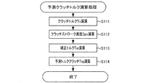
ステップS31において、制御部10(予測クラッチトルク演算部)は、「予測クラッチトルク演算処理」を実行して、予測クラッチトルクTcpを演算する。以下に、図6に示すフローチャートを用いて、「予測クラッチトルク演算処理」について説明する。
制御部10は、「予測クラッチトルク演算処理」を開始させると、プログラムをステップS111に進める。
ステップS111において、制御部10(クラッチトルク演算部)は、「クラッチトルクマップ」(図2示)を参照して、クラッチストロークセンサ54によって検出されたクラッチストロークStcに対応するクラッチトルクTcを演算する。
以下に、図5に示すフローチャートを用いて、「発進時エンジン制御」について説明する。制御部10は、「発進時エンジン制御」を開始させると、プログラムをステップS31に進める。
ステップS31において、制御部10(予測クラッチトルク演算部)は、「予測クラッチトルク演算処理」を実行して、予測クラッチトルクTcpを演算する。以下に、図6に示すフローチャートを用いて、「予測クラッチトルク演算処理」について説明する。
制御部10は、「予測クラッチトルク演算処理」を開始させると、プログラムをステップS111に進める。
ステップS111において、制御部10(クラッチトルク演算部)は、「クラッチトルクマップ」(図2示)を参照して、クラッチストロークセンサ54によって検出されたクラッチストロークStcに対応するクラッチトルクTcを演算する。
ステップS112において、制御部10(クラッチストローク速度演算部)は、クラッチストロークセンサ54によって検出されたクラッチストロークStcに基づいて、クラッチストロークStcの単位時間当たりの変化量であるクラッチストローク速度Spcを演算する。具体的には、制御部10は、今回ステップS112において検出されたクラッチストロークStcから前回ステップS112において検出されたクラッチストロークStcを減算した値を、前回のステップS112から今回のステップS112までの経過時間で除すことにより、クラッチストローク速度Spcを演算する。
ステップS113において、制御部10(補正トルク演算部)は、「補正トルクマップ」(図7示)を参照して、ステップS112において演算されたクラッチストローク速度Spc及びエンジン回転速度センサ24によって検出されたエンジン回転速度Neに対応する補正トルクTcrを演算する。ここで、図7に示す「補正トルクマップ」について説明する。図7に示すように、「補正トルクマップ」は、クラッチストローク速度Spc、エンジン回転速度Ne、及び補正トルクTcrの関係を表している。「補正トルクマップ」は、クラッチストローク速度Spcが正の値である場合には、補正トルクTcrが正の値となるように設定されている。また、「補正トルクマップ」は、クラッチストローク速度Spcが負の値である場合には、補正トルクTcrが負の値となるように設定されている。また、「補正トルクマップ」は、クラッチストローク速度Spcの絶対値が大きくなるに従って、補正トルクTcrの絶対値が大きくなるように設定されている。但し、クラッチストローク速度Spcの絶対値が大きい領域では、クラッチストローク速度Spcの絶対値が小さい領域に比べて、クラッチストローク速度Spcの変化量に対する補正トルクTcrの変化量(傾き)が大きくなっている。なお、クラッチストローク速度Spcの絶対値が規定値以下では、補正トルクTcrが0となっている不感帯が設けられている実施形態であっても差し支え無い。「補正トルクマップ」は、アクセルペダル51が操作されている場合の「アクセル操作時補正トルクマップ」と、アクセルペダル51が操作されていない場合の「アクセル非操作時補正トルクマップ」とを有している。「アクセル非操作時補正トルクマップ」の補正トルクTcrの絶対値は、「アクセル操作時補正トルクマップ」の補正トルクTcrの絶対値よりも大きく設定されている。「アクセル操作時補正トルクマップ」では、エンジン回転速度Neが遅くなるに従って、補正トルクTcrの絶対値が大きくなるように設定されている。制御部10(補正トルク演算部)は、アクセルストロークセンサ52からの検出結果に基づいて、アクセルペダル51が操作されていると判断した場合には、「アクセル操作時補正トルクマップ」を参照して、補正トルクTcrを演算する。一方で、制御部10(補正トルク演算部)は、アクセルストロークセンサ52からの検出結果に基づいて、アクセルペダル51が操作されていないと判断した場合には、「アクセル非操作時補正トルクマップ」を参照して、補正トルクTcrを演算する。
ステップS114において、制御部10(予測クラッチトルク演算部)は、演算されたクラッチトルクTc及び補正トルクTcrを上式(2)に代入して、これらを加算することにより、予測クラッチトルクTcpを演算する。ステップS114が終了すると、「予測クラッチトルク演算処理」が終了し、制御部10は、プログラムを図5のステップS32に進める。
ステップS32において、制御部10(エンジン回転速度調整トルク演算部)は、「エンジン回転速度調整トルク処理」を実行して、エンジン回転速度調整トルクTeaを演算する。以下に、図8に示すフローチャートを用いて、「エンジン回転速度調整トルク演算処理」について説明する。制御部10が、「エンジン回転速度調整トルク演算処理」を開始させると、プログラムをステップS211に進める。
ステップS211において、制御部10(目標エンジン回転速度演算部)は、図9に示す「目標エンジン回転速度マップ」を参照して、アクセルストロークセンサ52によって検出されたアクセルストロークStaに対応する目標エンジン回転速度Netを演算する。「目標エンジン回転速度マップ」は、アクセルストロークStaと目標エンジン回転速度Netとの関係を表したマップである。「目標エンジン回転速度マップ」は、アクセルストロークStaが大きくなるに従って、目標エンジン回転速度Netが速くなるように設定されている。なお、アクセルストロークStaが0の場合の目標エンジン回転速度Netは、アイドリング回転速度よりも速く設定されている。アクセルストロークStaが最大の場合の目標エンジン回転速度Netは、最大のエンジン回転速度Neよりも遅く設定されている。
ステップS212において、制御部10は、ステップS211において演算した目標エンジン回転速度Netからエンジン回転速度センサ24によって検出された現時点のエンジン回転速度Neを減算して、エンジン差回転速度ΔNeを演算する。
ステップS213において、制御部10(エンジン回転速度調整トルク演算部)は、図10に示す「エンジン回転速度調整トルクマップ」を参照して、ステップS212において演算したエンジン差回転速度ΔNeに対応するエンジン回転速度調整トルクTeaを演算する。「エンジン回転速度調整トルクマップ」は、エンジン差回転速度ΔNeとエンジン回転速度調整トルクTeaとの関係を表したマップである。「エンジン回転速度調整トルクマップ」は、エンジン差回転速度ΔNeが正の値である場合には、エンジン回転速度調整トルクTeaが正の値となるように設定されている。また、「エンジン回転速度調整トルクマップ」は、エンジン差回転速度ΔNeが負の値である場合には、エンジン回転速度調整トルクTeaが負の値となるように設定されている。また、エンジン差回転速度ΔNeの絶対値が大きくなるに従って、エンジン回転速度調整トルクTeaの絶対値が大きくなるように設定されている。「エンジン回転速度調整トルクマップ」は、「アクセル操作時エンジン回転速度調整トルクマップ」と「アクセル非操作時エンジン回転速度調整トルクマップ」とを有している。「アクセル非操作時エンジン回転速度調整トルクマップ」は、「アクセル操作時エンジン回転速度調整トルクマップ」に対して、エンジン回転速度調整トルクTeaをエンジン差回転速度ΔNeで除算した傾きが大きくなっている。言い換えると、「アクセル非操作時エンジン回転速度調整トルクマップ」は、「アクセル操作時エンジン回転速度調整トルクマップ」に比べて、エンジン回転速度調整トルクTeaの絶対値が大きくなっている。
制御部10(エンジン回転速度調整トルク演算部)は、アクセルストロークセンサ52からの検出結果に基づいて、アクセルペダル51が操作されている(踏まれている)と判断した場合には、「アクセル操作時エンジン回転速度調整トルクマップ」を参照して、エンジン回転速度調整トルクTeaを演算する。一方で、制御部10(エンジン回転速度調整トルク演算部)は、アクセルストロークセンサ52からの検出結果に基づいて、アクセルペダル51が操作されていない(踏まれていない)と判断した場合には、「アクセル非操作時エンジン回転速度調整トルクマップ」を参照して、エンジン回転速度調整トルクTeaを演算する。これにより、アクセルペダル51が操作されていない場合には、アクセルペダル51が踏まれている場合よりも、より絶対値が大きな値のエンジン回転速度調整トルクTeaが演算される。ステップS213が終了すると、「エンジン回転速度調整トルク演算処理」が終了し、制御部10は、プログラムを図5のステップS33に進める。
ステップS33において、制御部10(維持トルク演算部)は、「維持トルク演算処理」を実行して、維持トルクTkを演算する。以下に、図11に示すフローチャートを用いて、「維持トルク演算処理」について説明する。
制御部10が、「維持トルク演算処理」を開始させると、プログラムをステップS311に進める。
ステップS311において、制御部10(負荷演算部)は、「エンジンフリクショントルクマップ」(不図示)を参照して、油温センサ25によって検出されたエンジンオイルの油温t及びエンジン回転速度センサ24によって検出されたエンジン回転速度Neに対応するエンジンフリクショントルクTefを演算する。なお、「エンジンフリクショントルクマップ」は、油温t、エンジン回転速度Ne、及びエンジンフリクショントルクTefの関係を表したマップである。また、「エンジンフリクショントルクマップ」は、検出された油温tが低くなるに従って、演算されるエンジンフリクショントルクTefが大きくなるように設定されている。また、「エンジンフリクショントルクマップ」は、検出されたエンジン回転速度Neが速くなるに従って、演算されるエンジンフリクショントルクTefが大きくなるように設定されている。
制御部10が、「維持トルク演算処理」を開始させると、プログラムをステップS311に進める。
ステップS311において、制御部10(負荷演算部)は、「エンジンフリクショントルクマップ」(不図示)を参照して、油温センサ25によって検出されたエンジンオイルの油温t及びエンジン回転速度センサ24によって検出されたエンジン回転速度Neに対応するエンジンフリクショントルクTefを演算する。なお、「エンジンフリクショントルクマップ」は、油温t、エンジン回転速度Ne、及びエンジンフリクショントルクTefの関係を表したマップである。また、「エンジンフリクショントルクマップ」は、検出された油温tが低くなるに従って、演算されるエンジンフリクショントルクTefが大きくなるように設定されている。また、「エンジンフリクショントルクマップ」は、検出されたエンジン回転速度Neが速くなるに従って、演算されるエンジンフリクショントルクTefが大きくなるように設定されている。
ステップS312において、制御部10(負荷演算部)は、補機トルクTaを演算する。補機トルクTaとは、エンジン2のクランクシャフト21に連結している補機を駆動するために必要なトルクであり、前記補機のフリクショントルク及びイナーシャトルクの総計である。以下に、補機の1つであるエアコンディショナー27のコンプレッサ27aのコンプレッサ補機トルクTacの演算方法について説明する。制御部10は、エアコンディショナー27がON状態では、「コンプレッサ補機トルクマップ」(不図示)を参照して、エンジン回転速度センサ24によって検出されたエンジン回転速度Neに対応するコンプレッサ補機トルクTacを演算する。なお、「コンプレッサ補機トルクマップ」は、エンジン回転速度Neとコンプレッサ補機トルクTacとの関係を表したマップである。また、「コンプレッサ補機トルクマップ」は、検出されたエンジン回転速度Neが速くなるに従って、演算されるコンプレッサ補機トルクTacが大きくなるように設定されている。エアコンディショナー27がOFF状態では、制御部10は、コンプレッサ補機トルクTacを0と演算する。
コンプレッサ補機トルクTacの演算手法と同様の方法で、制御部10は、補機の1つであるジェネレータ26のジェネレータ補機トルクTagや、その他、エンジン2のクランクシャフト21に連結している補機の補機トルクを演算する。そして、制御部10は、コンプレッサ補機トルクTacやジェネレータ補機トルクTag等の補機トルクを合算して、補機トルクTaを演算する。
ステップS313において、制御部10は、調整トルクTαを演算する。調整トルクTαは、エンジンフリクショントルクTef及び補機トルクTa以外に、エンジン回転速度Neを維持するのに必要なトルクであり、エンジン回転速度Ne等の情報に基づいて演算される。
ステップS314において、制御部10(維持トルク演算部)は、下式(4)に基づいて、維持トルクTkを演算する。
Tk=Tef+Ta+Tα…(4)
Tk…維持トルク
Tef…エンジンフリクショントルク
Ta…補機トルク
Tα…調整トルク
ステップS314が終了すると、「維持トルク演算処理」が終了し、プログラムは、図5のステップS34に進む。
Tk=Tef+Ta+Tα…(4)
Tk…維持トルク
Tef…エンジンフリクショントルク
Ta…補機トルク
Tα…調整トルク
ステップS314が終了すると、「維持トルク演算処理」が終了し、プログラムは、図5のステップS34に進む。
ステップS34において、制御部10(目標エンジントルク演算部)は、上記演算した、予測クラッチトルクTcp、エンジン回転速度調整トルクTea、及び維持トルクTkを上式(1)に代入することにより、これらを合算して、目標エンジントルクTegを演算する。
ステップS35において、制御部10(エンジン制御部)は、エンジン2が発生するエンジントルクTeが目標エンジントルクTegとなるように、エンジン2を制御する。ステップS35が終了すると、「発進時エンジン制御」が終了し、プログラムはステップS11に戻る。
(復帰制御)
以下に、図12に示すフローチャートを用いて、「復帰制御」について説明する。制御部10は、「復帰制御」を開始させると、プログラムをステップS41に進める。
ステップS41において、制御部10(予測クラッチトルク演算部)は、上述した図5に示すステップS31の処理と同一の処理によって、予測クラッチトルクTcpを演算する。
ステップS42において、制御部10(エンジン回転速度調整トルク演算部)は、上述した図5に示すステップS32の処理と同一の処理によって、エンジン回転速度調整トルクTeaを演算する。
ステップS43において、制御部10(維持トルク演算部)は、上述した図5に示すステップS33の処理と同一の処理によって、維持トルクTkを演算する。
ステップS44において、制御部10(目標エンジントルク演算部)は、上述した図5に示すステップS34の処理と同一の処理によって、目標エンジントルクTegを演算する。
ステップS45において、制御部10は、アクセルストロークセンサ52によって検出されたアクセルストロークStaに基づいて、要求エンジントルクTerを演算する。
以下に、図12に示すフローチャートを用いて、「復帰制御」について説明する。制御部10は、「復帰制御」を開始させると、プログラムをステップS41に進める。
ステップS41において、制御部10(予測クラッチトルク演算部)は、上述した図5に示すステップS31の処理と同一の処理によって、予測クラッチトルクTcpを演算する。
ステップS42において、制御部10(エンジン回転速度調整トルク演算部)は、上述した図5に示すステップS32の処理と同一の処理によって、エンジン回転速度調整トルクTeaを演算する。
ステップS43において、制御部10(維持トルク演算部)は、上述した図5に示すステップS33の処理と同一の処理によって、維持トルクTkを演算する。
ステップS44において、制御部10(目標エンジントルク演算部)は、上述した図5に示すステップS34の処理と同一の処理によって、目標エンジントルクTegを演算する。
ステップS45において、制御部10は、アクセルストロークセンサ52によって検出されたアクセルストロークStaに基づいて、要求エンジントルクTerを演算する。
ステップS46において、制御部10は、ステップS44で演算した目標エンジントルクTeg及びステップS45で演算した要求エンジントルクTerに基づいて、復帰制御時エンジントルクTert(図13示)を演算する。具体的には、制御部10は、ステップS44で演算した目標エンジントルクTeg及びステップS45で演算した要求エンジントルクTerを、下式(5)に代入することにより、復帰制御時エンジントルクTertを演算する。
Tert=Teg×(a-b)+Ter×b…(5)
Tert:復帰制御時エンジントルク
Teg:目標エンジントルク
Ter:要求エンジントルク
a:復帰時間
b:復帰制御開始経過時間
復帰時間a(図13示)とは、「復帰制御」の実行により、エンジン2が発生するエンジントルクTeが、目標エンジントルクTegから要求エンジントルクTerに復帰するのに要する時間(例えば、1秒)である。
復帰制御開始経過時間b(図13示)とは、「復帰制御」の実行が開始されて(図13のT1)からの経過時間である。
Tert=Teg×(a-b)+Ter×b…(5)
Tert:復帰制御時エンジントルク
Teg:目標エンジントルク
Ter:要求エンジントルク
a:復帰時間
b:復帰制御開始経過時間
復帰時間a(図13示)とは、「復帰制御」の実行により、エンジン2が発生するエンジントルクTeが、目標エンジントルクTegから要求エンジントルクTerに復帰するのに要する時間(例えば、1秒)である。
復帰制御開始経過時間b(図13示)とは、「復帰制御」の実行が開始されて(図13のT1)からの経過時間である。
ステップS47において、制御部10は、ステップS46で演算した復帰制御時エンジントルクTertとステップS45で演算した要求エンジントルクTerとのトルク差ΔTが規定トルク(例えば、1Nm)以下であると判断した場合には(ステップS47:YES)、「復帰制御」を終了させて、プログラムを図4のステップS60に進める。一方で、制御部10は、ステップS46で演算した復帰制御時エンジントルクTertとステップS45で演算した要求エンジントルクTerとのトルク差ΔTが規定トルクよりも大きいと判断した場合には(ステップS47:NO)、プログラムをステップS48に進める。上記規定トルクは小さい値(例えば、1Nm)であり、上記トルク差Δが規定トルク以下となった場合には、復帰制御時エンジントルクTertと要求エンジントルクTerとが殆ど同一になったと同視できる。
ステップS48において、制御部10は、エンジン2が発生するエンジントルクTeが、ステップS46で演算した復帰制御時エンジントルクTertとなるように、エンジン2を制御する。「復帰制御」の実行によって、図13に示すように、復帰時間aの間に、エンジン2が発生するエンジントルクTeが、目標エンジントルクTegから要求エンジントルクTerに徐変する。そして、復帰制御時エンジントルクTertと要求エンジントルクTerとのトルク差ΔTが規定トルク以下となり(ステップS47:YES)、復帰制御時エンジントルクTertと要求エンジントルクTerとが殆ど同一になった場合に(図13のT2)、プログラムは図4のステップS60に進む。そして、ステップS60において、上述したように、エンジン2が発生するエンジントルクTeが要求エンジントルクTerとなるように、エンジン2が制御される。
図14に示すように、目標エンジントルクTegが要求エンジントルクTerよりも大きい場合において、「復帰制御」中に、要求エンジントルクTerが上昇して、復帰制御時エンジントルクTertと要求エンジントルクTerとのトルク差ΔTが規定トルク以下となった場合には(ステップS47:YES)、復帰時間aの経過を待たずに、プログラムは図4のステップS60に進む。そして、ステップS60において、上述したように、エンジン2が発生するエンジントルクTeが要求エンジントルクTerとなるように、エンジン2が制御される。
(本実施形態の効果)
上述した説明から明らかなように、制御部10(目標エンジントルク演算部)は、上式(1)及び(2)(上式(3))によって、クラッチストロークStc及びクラッチストローク速度Spcに基づいて目標エンジントルクTegを演算する。これにより、クラッチストローク速度Spcに対応したトルクである補正トルクTcrが加味された目標エンジントルクTegが演算される。このため、クラッチペダル53(クラッチ操作部材)の操作によるクラッチトルクTcの変化に対するエンジン2の応答遅れが発生する前に、クラッチストローク速度Spcの増減分に対応したトルクである補正トルクTcrによってエンジン2の応答遅れが相殺され、エンジン2の応答遅れが抑制される。この結果、エンジン2の応答遅れに起因するエンジン回転速度Neの低下及び上昇が抑制され、車両100の発進時におけるエンジンストール及びエンジン2における騒音の発生が抑制される。
上述した説明から明らかなように、制御部10(目標エンジントルク演算部)は、上式(1)及び(2)(上式(3))によって、クラッチストロークStc及びクラッチストローク速度Spcに基づいて目標エンジントルクTegを演算する。これにより、クラッチストローク速度Spcに対応したトルクである補正トルクTcrが加味された目標エンジントルクTegが演算される。このため、クラッチペダル53(クラッチ操作部材)の操作によるクラッチトルクTcの変化に対するエンジン2の応答遅れが発生する前に、クラッチストローク速度Spcの増減分に対応したトルクである補正トルクTcrによってエンジン2の応答遅れが相殺され、エンジン2の応答遅れが抑制される。この結果、エンジン2の応答遅れに起因するエンジン回転速度Neの低下及び上昇が抑制され、車両100の発進時におけるエンジンストール及びエンジン2における騒音の発生が抑制される。
具体的には、車両100の発進中において、運転者がクラッチペダル53を戻した場合には、クラッチストローク速度Spcが増大する(図3のf15)。すると、上式(2)によって、クラッチストロークStcに基づいて演算されたクラッチトルクTcにクラッチストローク速度Spcの増大分に基づく補正トルクTcr(図3のf16)が加算されて予測クラッチトルクTcpが演算される。そして、上式(1)によって、予測クラッチトルクTcpに基づいて目標エンジントルクTegが演算される。そして、エンジントルクTeが目標エンジントルクTegとなるように、エンジン2が制御される。このように、エンジン2の応答遅れを見込んだ分のトルク、つまり、クラッチストローク速度Spcの増大分に基づいて演算された補正トルクTcrだけエンジントルクTeを増大させる指令がエンジン2に入力される。このため、補正トルクTcrによってエンジン2の応答遅れが相殺され、エンジン2の応答遅れが抑制される。この結果、車両100の発進時におけるエンジンストールの発生や、車両100の加速遅れが抑制される。
また、車両100の発進時に、運転者がアクセルペダル51を踏んでいて、クラッチ3が半クラッチとなっている状態で(図3のT6~T8)、運転者がクラッチペダル53を踏み込んだ場合には、クラッチストローク速度Spcが減少する(図3のf9)。すると、上式(1)、(2)(上式(3))によって、クラッチストロークStcに基づいて演算されたクラッチトルクTcに、クラッチストローク速度Spcの減少分に基づいて演算された補正トルクTcr(図3のf10)の絶対値が減算されて目標エンジントルクTegが演算される。そして、エンジントルクTeが目標エンジントルクTegとなるように、エンジン2が制御される。このように、エンジン2の応答遅れを見込んだ分のトルク、つまり、クラッチストローク速度Spcの減少分に基づいて演算された補正トルクTcrの絶対値だけエンジントルクを減少させる指令がエンジン2に入力される。このため、補正トルクTcrによってエンジン2の応答遅れが相殺され、エンジン2の応答遅れが抑制される。この結果、エンジン2の応答遅れに起因するエンジン回転速度Neの上昇(図3のf12)が抑制され、エンジン回転速度Neの上昇に伴うエンジン2における騒音の発生や、エンジン2における無駄な燃料消費が抑制される。
制御部10(補正トルク演算部)は、クラッチストローク速度Spcに基づいて、補正トルクTcrを演算する。そして、制御部10(予測クラッチトルク演算部)は、上式(2)によって、クラッチトルクTc及び補正トルクTcrに基づいて、予測クラッチトルクTcpを演算する。そして、制御部10(目標エンジントルク演算部)は、上式(1)によって、予測クラッチトルクTcpに基づいて、目標エンジントルクTegを演算する。本実施形態では、制御部10(補正トルク演算部)は、図7に示す「補正トルクマップ」(補正トルク関係)を参照することにより、クラッチストローク速度Spcに基づいて、補正トルクTcrを演算している。これにより、制御部10(補正トルク演算部)は、エンジン2の応答遅れに対応した適正な「補正トルクマップ」を参照することにより、適正な補正トルクTcrを演算することができる。このため、エンジン2の応答遅れが適正に抑制される。つまり、エンジン2の応答遅れが解消されないことや、エンジン2の応答が過剰となることが抑制される。
エンジン回転速度Neが遅くなるに従って、エンジン2の応答遅れは増大する。そこで、図7に示すように、「補正トルクマップ」(補正トルク関係)は、エンジン回転速度Neが遅くなるに従って、補正トルクTcrの絶対値が大きくなるように設定されている。これにより、制御部10(補正トルク演算部)は、エンジン回転速度センサ24によって検出されたエンジン2の回転速度が遅くなるに従って、絶対値がより大きい値の補正トルクTcrを演算する。このため、エンジン回転速度Neが遅い領域におけるエンジン2の応答遅れが抑制される。また、エンジン回転速度Neが速い領域において、エンジン回転速度Neが過敏に増減することが抑制される。
クラッチストローク速度Spcの絶対値が大きい領域では、クラッチストローク速度Spcの絶対値が小さい領域に比べて、エンジン2の応答遅れはより長くなる。そこで、図7に示すように、「補正トルクマップ」(補正トルク関係)は、クラッチストローク速度Spcの絶対値が大きい領域では、クラッチストローク速度Spcの絶対値が小さい領域に比べて、クラッチストローク速度Spcに対する補正トルクTcrの変化量が大きく設定されている。これにより、クラッチストローク速度Spcの絶対値が大きい領域では、クラッチストローク速度Spcの絶対値が小さい領域と比べて、クラッチストローク速度Spcの絶対値の増加に対して補正トルクTcrの絶対値の増加量がより大きな補正トルクTcrが演算される。このため、クラッチストローク速度Spcの絶対値が大きい領域において、エンジン2の応答遅れが抑制される。一方で、クラッチストローク速度Spcの絶対値が小さい領域では、クラッチストローク速度Spcの絶対値が大きい領域と比べて、クラッチストローク速度Spcの絶対値の増加に対して補正トルクTcrの絶対値の増加量がより小さな補正トルクTcrが演算される。このため、クラッチストローク速度Spcの絶対値が小さい領域において、エンジン回転速度Neが過敏に増減することが抑制される。
制御部10(目標エンジントルク演算部)は、クラッチストロークStcが非伝達領域(図2示)にあり、タッチ点Ptに到達していない場合においても、クラッチストローク速度Spcに基づいて目標エンジントルクTegを演算する。これにより、クラッチストロークStcが非伝達領域にあり、クラッチトルクTcが実際に発生していない状態でも、クラッチストローク速度Spcに基づいて目標エンジントルクTegが演算され、エンジントルクTeが目標エンジントルクTegとなるようにエンジン2が制御される。このため、エンジン2の応答遅れが確実に抑制される。
図7に示すように、「アクセル非操作時補正トルクマップ」(アクセル非操作時補正トルク関係)の補正トルクTcrの絶対値は、「アクセル操作時補正トルク関係」(アクセル操作時補正トルク関係)の補正トルクTcrの絶対値よりも大きく設定されている。車両100の発進時に、運転者がアクセルペダル51を操作していない状態では、運転者は車両100の発進時におけるエンジン2の制御を車両100に委ねている。このため、運転者がアクセルペダル51を操作している場合と比べて、補正トルクTcrの絶対値が大きく演算されても、運転者は違和感を覚えにくい。そして、運転者がアクセルペダル51を操作していない状態では、補正トルクTcrの絶対値が大きく演算されるので、エンジン2の応答遅れがより抑制される。このため、運転者がアクセルペダル51を操作していない状態において、運転者の違和感が抑制されつつ、車両100の発進時におけるエンジンストールの発生や、車両100の加速遅れがより確実に抑制される。
制御部10(エンジン回転速度調整トルク演算部)は、図8のステップS213において、エンジン回転速度Neを目標エンジン回転速度Netにするためのトルクであるエンジン回転速度調整トルクTeaを演算する。そして、制御部10(目標エンジントルク演算部)は、エンジン回転速度調整トルクTeaに基づいて、目標エンジントルクTegを演算する。これにより、エンジン回転速度Neが目標エンジン回転速度Netから乖離した場合に、エンジン回転速度Neが車両100の発進時における目標とされるエンジン回転速度Neである目標エンジン回転速度Netとなるように、エンジン2が制御される。このため、車両100の発進時におけるエンジンストールの発生や、車両100の加速遅れがより確実に抑制される。
図9に示すように、「目標エンジン回転速度マップ」(目標エンジン回転速度関係)は、アクセルストロークStaが大きくなるに従って、目標エンジン回転速度Netが速くなるように設定されている。これにより、図8のステップS211において、運転者によるアクセルペダル51の操作量(アクセルストロークSta)が大きくなるに従って、より速い目標エンジン回転速度Netが演算される。このため、「発進時エンジン制御」において、エンジン2が、運転者の意図に沿ったエンジン回転速度Neに制御され、運転者が違和感を覚えない。つまり、「発進時エンジン制御」において、運転者によるアクセルペダル51の操作が全くエンジン2の制御に反映されないとすると、運転者がアクセルペダル51を踏み込んだとしても、エンジン回転速度Neが上昇しないので、運転者が違和感を覚える。一方で、本実施形態では、「発進時エンジン制御」において、運転者がアクセルペダル51を踏み込むと、アクセルストロークStaに応じた目標エンジン回転速度Netが演算され、エンジン回転速度Neが上昇する。このため、運転者が違和感を覚えない。
本実施形態では、アクセルストロークStaが0の場合の目標エンジン回転速度Netは、アイドリング回転速度よりも速く設定されている。これにより、運転者がアクセルペダル51を踏んでいない場合であっても、エンジン回転速度Neがアイドリング回転速度よりも速い回転速度に制御される。このため、エンジンストールの発生がより確実に抑制される。また、本実施形態では、アクセルストロークStaが最大の場合の目標エンジン回転速度Netは、最大のエンジン回転速度Neよりも遅く設定されている。これにより、車両100の発進時において、運転者がアクセルペダル51を過度に踏み込んだ場合であっても、エンジン回転速度Neの上昇が抑制される。このため、エンジン2における騒音の発生や、エンジン2における無駄な燃料消費が抑制される。また、エンジン回転速度Neが速い状態でクラッチ3が係合されることに起因するクラッチ3の破損が抑制される。
図10に示すように、「アクセル非操作時エンジン回転速度調整トルクマップ」は、「アクセル操作時エンジン回転速度調整トルクマップ」に対して、エンジン回転速度調整トルクTeaをエンジン差回転速度ΔNeで除算した傾きが大きくなっている。制御部10(エンジン回転速度調整トルク演算部)は、アクセルストロークセンサ52からの検出結果に基づいて、アクセルペダル51が操作されている(踏まれている)と判断した場合には、「アクセル操作時エンジン回転速度調整トルクマップ」を参照して、エンジン回転速度調整トルクTeaを演算する。一方で、制御部10(エンジン回転速度調整トルク演算部)は、アクセルストロークセンサ52からの検出結果に基づいて、アクセルペダル51が操作されていない(踏まれていない)と判断した場合には、「アクセル非操作時エンジン回転速度調整トルクマップ」を参照して、エンジン回転速度調整トルクTeaを演算する。これにより、アクセルペダル51が操作されていない場合には、アクセルペダル51が踏まれている場合よりも、より絶対値が大きな値のエンジン回転速度調整トルクTeaが演算される。車両100の発進時に、運転者がアクセルペダル51を操作していない状態では、運転者は車両100の発進時におけるエンジン2の制御を車両100に委ねている。このため、運転者がアクセルペダル51を操作している場合と比べて、エンジン回転速度調整トルクTeaの絶対値が大きく演算されても、運転者は違和感を覚えにくい。そして、運転者がアクセルペダル51を操作していない状態では、エンジン回転速度調整トルクTeaの絶対値が大きく演算されるので、エンジン回転速度Neの目標エンジン回転速度Netからの乖離がより迅速に解消される。このため、運転者がアクセルペダル51を操作していない状態において、運転者の違和感が抑制されつつ、車両100の発進時におけるエンジンストールの発生や、車両100の加速遅れがより確実に抑制される。
制御部10(負荷演算部)は、図11のステップS311、S312において、エンジン2に作用する負荷であるエンジンフリクショントルクTefや補機トルクTaを演算する。そして、制御部10(維持トルク演算部)は、図11のステップS314において、エンジンフリクショントルクTefや補機トルクTaに基づいて、エンジン回転速度Neを維持するのに必要なトルクである維持トルクTkを演算する。そして、制御部10(目標エンジントルク演算部)は、図5のステップS34において、維持トルクTkに基づいて、目標エンジントルクTegを演算する。これにより、エンジン2により駆動される補機であるコンプレッサ27aの稼働や稼働の停止、或いはジェネレータ26による発電量の変動によって、エンジン2に作用する負荷が変動した場合に、当該負荷に基づいた維持トルクTkが演算される。このため、車両100の発進時にエンジン2に作用する負荷が変動した場合であっても、エンジン2に作用する負荷に基づいた維持トルクTkが加味された適正な目標エンジントルクTegが演算される。この結果、車両100の発進時におけるエンジンストールの発生や、エンジン回転速度Neの上昇、車両100の加速遅れがより確実に抑制される。
(第二実施形態の予測クラッチトルク演算処理)
以下に、第二実施形態の「予測クラッチトルク演算処理」について、図15に示すフローチャートを用いて、第一実施形態の「予測クラッチトルク演算処理」(図6示)と異なる点について説明する。第二実施形態の「予測クラッチトルク演算処理」では、クラッチストロークStc及びクラッチストローク速度Spcから予測クラッチストロークStcpが演算される。そして、図2に示す「クラッチトルクマップ」が参照されて、この予測クラッチストロークStcpに対応する予測クラッチトルクTcpが演算される。
以下に、第二実施形態の「予測クラッチトルク演算処理」について、図15に示すフローチャートを用いて、第一実施形態の「予測クラッチトルク演算処理」(図6示)と異なる点について説明する。第二実施形態の「予測クラッチトルク演算処理」では、クラッチストロークStc及びクラッチストローク速度Spcから予測クラッチストロークStcpが演算される。そして、図2に示す「クラッチトルクマップ」が参照されて、この予測クラッチストロークStcpに対応する予測クラッチトルクTcpが演算される。
図15のステップS115において、制御部10(予測クラッチストローク演算部)は、下式(6)にクラッチストロークStc及びクラッチストローク速度Spcを代入することにより、予測クラッチストロークStcpを演算する。
Stcp=Stc+Spc×A…(6)
Stcp:予測クラッチストローク
Stc:クラッチストローク
Spc:クラッチストローク速度
A:係数
なお、係数Aは、エンジン2の応答遅れが解消されるように設定された設定値である。
Stcp=Stc+Spc×A…(6)
Stcp:予測クラッチストローク
Stc:クラッチストローク
Spc:クラッチストローク速度
A:係数
なお、係数Aは、エンジン2の応答遅れが解消されるように設定された設定値である。
クラッチペダル53が踏まれ、クラッチストロークStcが増加する場合には、現在のクラッチストロークStc(図2のp1)に、クラッチストローク速度Spcに係数Aを乗算した値(Spc×A)を加算した値の予測クラッチストロークStcp(図2のp2)が演算される。一方で、クラッチペダル53が戻され、クラッチストロークStcが減少する場合には、現在のクラッチストロークStc(図2のp1)からクラッチストローク速度Spcに係数Aを乗算した値(Spc×A)の絶対値を減算した値の予測クラッチストロークStcp(図2のp3)が演算される。このようなクラッチストローク速度Spcに係数Aを乗算した値(Spc×A)は、未来のクラッチストロークStcの増減量の予測値であるといえる。そして、予測クラッチストロークStcpは、未来のクラッチストロークStcの予測値であるといえる。
ステップS116において、制御部10(予測クラッチトルク演算部)は、図2に示すクラッチストロークStcとクラッチトルクTcとの関係を表した「クラッチトルクマップ」を参照する。そして、制御部10(予測クラッチトルク演算部)は、ステップS115で演算した予測クラッチストロークStcpをクラッチストロークStcとし、このクラッチストロークStcに対応するクラッチトルクTcを演算する。そして、制御部10(予測クラッチトルク演算部)は、この演算したクラッチトルクTcを、予測クラッチトルクTcpとして演算する。
クラッチペダル53が踏まれ、クラッチストロークStcが増加する場合には、クラッチストローク速度Spcに係数Aを乗算した値(Spc×A)に相当するクラッチトルクTcaが現在のクラッチトルクTcに加算されて予測クラッチトルクTcp(図2のp4)が演算される。一方で、クラッチペダル53が戻され、クラッチストロークStcが減少する場合には、クラッチストローク速度Spcに係数Aを乗算した値(Spc×A)に相当するクラッチトルクTcbが現在のクラッチトルクTcから減算されて予測クラッチトルクTcp(図2のp5)が演算される。このように、現在のクラッチストロークStcにクラッチストローク速度Spcに係数Aを乗算した値(Spc×A)を加算した値である予測クラッチストロークStcpは、未来のクラッチストロークStcの予測値であるといえる。
(第二実施形態の効果)
以上の説明から明らかなように、制御部10(予測クラッチストローク演算部)は、上式(6)を用いて、クラッチストロークStc及びクラッチストローク速度Spcに基づいて、未来のクラッチストロークStcの予測値である予測クラッチストロークStcpを演算する(図15のステップS115)。そして、制御部10(予測クラッチトルク演算部)は、図2に示す「クラッチトルクマップ」を参照する。そして、制御部10(予測クラッチトルク演算部)は、予測クラッチストロークStcpをクラッチストロークStcとし、このクラッチストロークStcに対応するクラッチトルクTcを演算する。そして、制御部10(予測クラッチトルク演算部)は、この演算したクラッチトルクTcを、予測クラッチトルクTcpとして演算する(図15のステップS116)。そして、制御部10(目標エンジントルク演算部)は、予測クラッチトルクTcpに基づいて、目標エンジントルクTegを演算する(図5のステップS34)。そして、制御部10(エンジン制御部)は、エンジントルクTeが目標エンジントルクTegとなるように、エンジン2を制御する(図5のステップS56)。
以上の説明から明らかなように、制御部10(予測クラッチストローク演算部)は、上式(6)を用いて、クラッチストロークStc及びクラッチストローク速度Spcに基づいて、未来のクラッチストロークStcの予測値である予測クラッチストロークStcpを演算する(図15のステップS115)。そして、制御部10(予測クラッチトルク演算部)は、図2に示す「クラッチトルクマップ」を参照する。そして、制御部10(予測クラッチトルク演算部)は、予測クラッチストロークStcpをクラッチストロークStcとし、このクラッチストロークStcに対応するクラッチトルクTcを演算する。そして、制御部10(予測クラッチトルク演算部)は、この演算したクラッチトルクTcを、予測クラッチトルクTcpとして演算する(図15のステップS116)。そして、制御部10(目標エンジントルク演算部)は、予測クラッチトルクTcpに基づいて、目標エンジントルクTegを演算する(図5のステップS34)。そして、制御部10(エンジン制御部)は、エンジントルクTeが目標エンジントルクTegとなるように、エンジン2を制御する(図5のステップS56)。
このように、エンジントルクTeが、予測クラッチストロークStcpに基づいて演算された目標エンジントルクTegとなるように、エンジン2が制御される。このため、図16に示すように、クラッチストロークStcが増大する状況では、クラッチストロークStcに基づいて演算された目標エンジントルクTegが増大を開始する時刻T2よりも前の時刻T1で、予測クラッチストロークStcpに基づいて演算された目標エンジントルクTegが増大する。上式(6)の係数Aは、時刻T1と時刻T2の時間差がエンジン2の応答遅れ時間となるように設定されている。このため、エンジン2の応答遅れが、時刻T2よりも前の時刻T1で増大を開始する目標エンジントルクTegによって相殺され、エンジントルクTeの増大開始が遅れることが抑制される。クラッチストロークStcが減少する場合でも、クラッチストロークStc基づいて演算された目標エンジントルクTegが減少を開始する時刻よりも前の時刻で、予測クラッチストロークStcpに基づいて演算された目標エンジントルクTegが減少を開始する。このため、エンジン2の応答遅れが抑制される。
言い換えて説明すると、エンジン2の応答遅れを見込んだ分のトルク、つまり、クラッチストローク速度Spcに係数Aを乗算した値(Spc×A)に相当するクラッチトルクTca、Tcbだけエンジントルクを増大又は減少させる指令がエンジン2に入力されることにより、上記クラッチトルクTca、Tcbによってエンジン2の応答遅れが相殺され、エンジン2の応答遅れが抑制される。このように、エンジントルクTeが、未来のクラッチストロークStcの予測値である予測クラッチストロークStcpに基づいて演算された目標エンジントルクTegとなるように、エンジン2が制御されるので、エンジン2の応答遅れが抑制され、エンジン2が応答良く反応する。
(別の実施形態)
以上説明した実施形態では、図6のステップS113において、制御部10(補正トルク演算部)は、「補正トルクマップ」(図7示)に基づいて、クラッチストローク速度Spc及びエンジン回転速度Neに対応する補正トルクTcrを演算している。しかし、制御部10(補正トルク演算部)が、クラッチストローク速度Spc、エンジン回転速度Ne、及び補正トルクTcrの関係を表した関係式(補正トルク関係)に基づいて、クラッチストローク速度Spc及びエンジン回転速度Neに対応する補正トルクTcrを演算する実施形態であっても差し支え無い。
以上説明した実施形態では、図6のステップS113において、制御部10(補正トルク演算部)は、「補正トルクマップ」(図7示)に基づいて、クラッチストローク速度Spc及びエンジン回転速度Neに対応する補正トルクTcrを演算している。しかし、制御部10(補正トルク演算部)が、クラッチストローク速度Spc、エンジン回転速度Ne、及び補正トルクTcrの関係を表した関係式(補正トルク関係)に基づいて、クラッチストローク速度Spc及びエンジン回転速度Neに対応する補正トルクTcrを演算する実施形態であっても差し支え無い。
以上説明した実施形態では、図8のステップS211において、制御部10(目標エンジン回転速度演算部)は、「目標エンジン回転速度マップ」(図9示)に基づいて、アクセルストロークStaに対応する目標エンジン回転速度Netを演算している。しかし、制御部10(目標エンジン回転速度演算部)が、アクセルストロークStaと目標エンジン回転速度Netとの関係を表した関係式(目標エンジン回転速度関係)に基づいて、アクセルストロークStaに対応する目標エンジン回転速度Netを演算する実施形態であっても差し支え無い。
以上説明した実施形態では、図8のステップS213において、制御部10(エンジン回転速度調整トルク演算部)は、「エンジン回転速度調整トルクマップ」(図10示)に基づいて、エンジン差回転速度ΔNeに対応するエンジン回転速度調整トルクTeaを演算している。しかし、制御部10(エンジン回転速度調整トルク演算部)が、エンジン差回転速度ΔNeとエンジン回転速度調整トルクTeaとの関係を表した関係式(エンジン回転速度調整トルク関係)に基づいて、エンジン差回転速度ΔNeに対応するエンジン回転速度調整トルクTeaを演算する実施形態であっても差し支え無い。
以上説明した実施形態では、クラッチストロークセンサ54は、クラッチペダル53のストロークをクラッチストロークStcとして検出している。しかし、クラッチストロークセンサ54は、クラッチ3のストロークをクラッチストロークStcとして検出するセンサであっても差し支え無い。この実施形態の場合には、クラッチストロークセンサ54は、クラッチディスク32、プレッシャプレート35、レリーズベアリング37、及びスレーブシリンダ38のいずれかストロークを検出する。
以上説明した実施形態では、クラッチペダル53の操作力は、マスタシリンダ55、作動圧配管58及びスレーブシリンダ38を介して、レリーズベアリング37に伝達させる。しかし、クラッチペダル53の操作力が、ワイヤ、ロッド、ギヤ等の機械的要素を介して、レリーズベアリング37に伝達される実施形態であっても差し支え無い。
以上説明した実施形態では、クラッチ3に運転者の操作力を伝達するクラッチ操作部材は、クラッチペダル53である。しかし、クラッチ操作部材は、クラッチペダル53に限定されず、例えば、クラッチレバーであっても差し支え無い。同様に、アクセルストロークStaを調整するアクセルペダル51の代わりに、例えば、アクセルストロークStaを調整するアクセルグリップであっても差し支え無い。そして、本実施形態の車両用駆動装置1を、自動二輪車やその他車両に適用しても、本発明の技術的思想が適用可能なことは言うまでもない。
1…車両用駆動装置、2…エンジン、3…クラッチ、4…マニュアルトランスミッション、10…制御部(クラッチストローク速度演算部、目標エンジントルク演算部、エンジン制御部、クラッチトルク演算部、クラッチストローク速度演算部、補正トルク演算部、予測クラッチトルク演算部、予測クラッチストローク演算部、エンジン回転速度調整トルク演算部、目標エンジントルク回転速度演算部、負荷演算部、維持トルク演算部)、18R,18L…駆動輪、24…エンジン回転速度センサ(エンジン回転速度検出部)、41…入力軸、42…出力軸、51…アクセルペダル(アクセル操作部)、52…アクセルストロークセンサ(アクセルストローク検出部)、53…クラッチペダル(クラッチ操作部材)、54…クラッチストロークセンサ(クラッチストローク検出部)、100…車両
Claims (10)
- エンジンが発生するエンジントルクが入力される入力軸と、車両の駆動輪に回転連結された出力軸とを備え、前記入力軸の回転速度を前記出力軸の回転速度で除した変速比が異なる複数の変速段が形成されるマニュアルトランスミッションと、
前記エンジンと前記入力軸との間に設けられ、前記エンジンと前記入力軸との間において伝達されるトルクであるクラッチトルクを可変とするクラッチと、
前記クラッチトルクを可変に操作するためのクラッチ操作部材のストローク又は前記クラッチのストロークであるクラッチストロークを検出するクラッチストローク検出部によって検出された前記クラッチストロークに基づいて、前記クラッチストロークの単位時間当たりの変化量であるクラッチストローク速度を演算するクラッチストローク速度演算部と、
前記クラッチストローク検出部によって検出された前記クラッチストローク及び前記クラッチストローク速度演算部によって演算された前記クラッチストローク速度に基づいて、前記車両の発進時における目標エンジントルクを演算する目標エンジントルク演算部と、
前記車両の発進時に、前記エンジンが発生する前記エンジントルクが、前記目標エンジントルク演算部によって演算された前記目標エンジントルクとなるように前記エンジンを制御するエンジン制御部と、を有する車両用駆動装置。 - 前記クラッチストローク検出部によって検出された前記クラッチストロークに基づいて、前記クラッチトルクを演算するクラッチトルク演算部と、
前記クラッチストローク速度演算部によって演算された前記クラッチストローク速度に基づいて、前記クラッチトルクを補正するための補正トルクを演算する補正トルク演算部と、
前記クラッチトルク演算部によって演算された前記クラッチトルク及び前記補正トルク演算部によって演算された前記補正トルクに基づいて、前記クラッチトルクの予測値である予測クラッチトルクを演算する予測クラッチトルク演算部と、を有し、
前記目標エンジントルク演算部は、前記予測クラッチトルク演算部によって演算された前記予測クラッチトルクに基づいて、前記目標エンジントルクを演算する請求項1に記載の車両用駆動装置。 - 前記エンジンの回転速度を検出するエンジン回転速度検出部を有し、
前記補正トルク演算部は、前記クラッチストローク速度、前記エンジンの回転速度、及び前記補正トルクの関係を表した補正トルク関係に基づいて、前記クラッチストローク速度演算部によって演算された前記クラッチストローク速度、及び前記エンジン回転速度検出部によって検出された前記エンジンの回転速度に対応する前記補正トルクを演算し、
前記補正トルク関係は、前記エンジンの回転速度が遅くなるに従って、前記補正トルクの絶対値が大きくなるように設定されている請求項2に記載の車両用駆動装置。 - 前記補正トルク演算部は、前記クラッチストローク速度と前記補正トルクとの関係を表した補正トルク関係に基づいて、前記クラッチストローク速度演算部によって演算された前記クラッチストローク速度に対応する前記補正トルクを演算し、
前記補正トルク関係は、前記クラッチストローク速度の絶対値が大きい領域では、前記クラッチストローク速度の絶対値が小さい領域に比べて、前記クラッチストローク速度の変化量に対する前記補正トルクの変化量が大きく設定されている請求項2に記載の車両用駆動装置。 - 前記エンジントルクを可変に操作するためのアクセル操作部のストロークであるアクセルストロークをアクセルストローク検出部により検出し、
前記補正トルク演算部は、前記クラッチストローク速度と前記補正トルクとの関係を表した補正トルク関係に基づいて、前記クラッチストローク速度演算部によって演算された前記クラッチストローク速度に対応する前記補正トルクを演算し、
前記補正トルク関係は、前記アクセル操作部が操作されている場合のアクセル操作時補正トルク関係と、前記アクセル操作部が操作されていない場合のアクセル非操作時補正トルク関係とを有し、
前記アクセル非操作時補正トルク関係の前記補正トルクの絶対値は、前記アクセル操作時補正トルク関係の前記補正トルクの絶対値よりも大きく設定され、
前記補正トルク演算部は、
前記アクセルストローク検出部によって検出された前記アクセルストロークに基づいて、前記アクセル操作部が操作されていると判断した場合には、前記アクセル操作時補正トルク関係に基づいて前記補正トルクを演算し、
前記アクセルストローク検出部によって検出された前記アクセルストロークに基づいて、前記アクセル操作部が操作されていないと判断した場合には、前記アクセル非操作時補正トルク関係に基づいて前記補正トルクを演算する請求項2に記載の車両用駆動装置。 - 前記クラッチストローク検出部によって検出された前記クラッチストローク及び前記クラッチストローク速度演算部によって演算された前記クラッチストローク速度に基づいて、前記クラッチストロークの予測値である予測クラッチストロークを演算する予測クラッチストローク演算部と、
前記クラッチストロークと前記クラッチトルクとの関係を表したクラッチトルクマップを参照して、前記予測クラッチストローク演算部によって演算された前記予測クラッチストロークを前記クラッチストロークとし、当該クラッチストロークに対応する前記クラッチトルクを演算し、この演算した前記クラッチトルクを前記クラッチトルクの予測値である予測クラッチトルクとして演算する予測クラッチトルク演算部と、を有し、
前記目標エンジントルク演算部は、前記予測クラッチトルク演算部によって演算された前記予測クラッチトルクに基づいて、前記目標エンジントルクを演算する請求項1に記載の車両用駆動装置。 - 前記エンジンの回転速度を検出するエンジン回転速度検出部によって検出された前記エンジンの回転速度に基づいて、前記エンジンの回転速度を前記車両の発進時における前記エンジンの目標とする回転速度である目標エンジン回転速度にするためのトルクであるエンジン回転速度調整トルクを演算するエンジン回転速度調整トルク演算部を有し、
前記目標エンジントルク演算部は、前記エンジン回転速度調整トルク演算部によって演算された前記エンジン回転速度調整トルクに基づいて、前記目標エンジントルクを演算する請求項1~請求項6のいずれか一項に記載の車両用駆動装置。 - 前記エンジントルクを可変に操作するためのアクセル操作部のストロークであるアクセルストロークをアクセルストローク検出部により検出し、
前記アクセルストロークと前記目標エンジン回転速度との関係を表した目標エンジン回転速度関係に基づいて、前記アクセルストローク検出部によって検出された前記アクセルストロークに対応する前記目標エンジン回転速度を演算する目標エンジン回転速度演算部を有し、
前記目標エンジン回転速度関係は、前記アクセルストロークが大きくなるに従って、前記目標エンジン回転速度が速くなるように設定されている請求項7に記載の車両用駆動装置。 - 前記エンジントルクを可変に操作するためのアクセル操作部のストロークであるアクセルストロークをアクセルストローク検出部により検出し、
前記エンジン回転速度調整トルク演算部は、前記アクセルストローク検出部によって検出された前記アクセルストロークに基づいて、前記アクセル操作部が操作されていないと判断した場合には、前記アクセル操作部が操作されていると判断した場合と比べて、前記エンジン回転速度調整トルクの絶対値が大きくなるように前記エンジン回転速度調整トルクを演算する請求項7又は請求項8に記載の車両用駆動装置。 - 前記エンジンに作用する負荷を演算する負荷演算部と、
前記負荷演算部によって演算された前記負荷に基づいて、前記エンジンの回転速度を維持するのに必要なトルクである維持トルクを演算する維持トルク演算部と、を有し、
前記目標エンジントルク演算部は、前記維持トルク演算部によって演算された前記維持トルクに基づいて、前記目標エンジントルクを演算する請求項1~請求項9のいずれか一項に記載の車両用駆動装置。
Applications Claiming Priority (2)
| Application Number | Priority Date | Filing Date | Title |
|---|---|---|---|
| JP2015013163A JP2016138488A (ja) | 2015-01-27 | 2015-01-27 | 車両用駆動装置 |
| JP2015-013163 | 2015-01-27 |
Publications (1)
| Publication Number | Publication Date |
|---|---|
| WO2016121261A1 true WO2016121261A1 (ja) | 2016-08-04 |
Family
ID=56542894
Family Applications (1)
| Application Number | Title | Priority Date | Filing Date |
|---|---|---|---|
| PCT/JP2015/085418 Ceased WO2016121261A1 (ja) | 2015-01-27 | 2015-12-17 | 車両用駆動装置 |
Country Status (2)
| Country | Link |
|---|---|
| JP (1) | JP2016138488A (ja) |
| WO (1) | WO2016121261A1 (ja) |
Families Citing this family (1)
| Publication number | Priority date | Publication date | Assignee | Title |
|---|---|---|---|---|
| JP2021014833A (ja) * | 2019-07-12 | 2021-02-12 | いすゞ自動車株式会社 | 車両の発進制御装置及び、発進制御方法 |
Citations (3)
| Publication number | Priority date | Publication date | Assignee | Title |
|---|---|---|---|---|
| JP2001182756A (ja) * | 1999-12-24 | 2001-07-06 | Aisin Seiki Co Ltd | クラッチ制御装置 |
| JP2004316432A (ja) * | 2003-04-10 | 2004-11-11 | Toyota Motor Corp | 車両用駆動力源の制御装置 |
| JP2014084813A (ja) * | 2012-10-25 | 2014-05-12 | Aisin Seiki Co Ltd | 車両用駆動装置 |
-
2015
- 2015-01-27 JP JP2015013163A patent/JP2016138488A/ja active Pending
- 2015-12-17 WO PCT/JP2015/085418 patent/WO2016121261A1/ja not_active Ceased
Patent Citations (3)
| Publication number | Priority date | Publication date | Assignee | Title |
|---|---|---|---|---|
| JP2001182756A (ja) * | 1999-12-24 | 2001-07-06 | Aisin Seiki Co Ltd | クラッチ制御装置 |
| JP2004316432A (ja) * | 2003-04-10 | 2004-11-11 | Toyota Motor Corp | 車両用駆動力源の制御装置 |
| JP2014084813A (ja) * | 2012-10-25 | 2014-05-12 | Aisin Seiki Co Ltd | 車両用駆動装置 |
Also Published As
| Publication number | Publication date |
|---|---|
| JP2016138488A (ja) | 2016-08-04 |
Similar Documents
| Publication | Publication Date | Title |
|---|---|---|
| JP6036473B2 (ja) | 車両用駆動装置 | |
| CN102947120B (zh) | 车辆的起步控制装置 | |
| US20170028990A1 (en) | Control device for vehicle | |
| WO2013150641A1 (ja) | 車両の発進クラッチ制御装置 | |
| JP5849928B2 (ja) | 車両用駆動装置 | |
| JP5653316B2 (ja) | 車両用クラッチ制御装置 | |
| JP5849929B2 (ja) | 車両用駆動装置 | |
| JP5849930B2 (ja) | 車両用駆動装置 | |
| JP2017061236A (ja) | 車両用駆動装置 | |
| WO2014174939A1 (ja) | 車両用駆動装置 | |
| JP2016138488A (ja) | 車両用駆動装置 | |
| JP2010276117A (ja) | 自動クラッチの制御装置 | |
| JP2017166338A (ja) | 車両用駆動装置 | |
| EP2565429B1 (en) | Vehicle engine controller | |
| JP6102499B2 (ja) | クラッチ操作状態判定装置 | |
| JP2013036486A (ja) | 車両用クラッチ制御装置 | |
| WO2016088223A1 (ja) | 車両用駆動装置 | |
| US20240209907A1 (en) | Vehicle, method for controlling vehicle and controller for vehicle | |
| JP2016114000A (ja) | 車両用駆動装置 | |
| JP2018076950A (ja) | 車両用駆動装置 | |
| JP2020204279A (ja) | 車両のエンジン制御装置 | |
| JP2017110710A (ja) | 車両用クラッチの制御装置 | |
| JP2011226550A (ja) | クラッチ制御装置 | |
| WO2016121162A1 (ja) | クラッチトルクマップ演算装置 | |
| JP2018091383A (ja) | 車両の制御装置 |
Legal Events
| Date | Code | Title | Description |
|---|---|---|---|
| 121 | Ep: the epo has been informed by wipo that ep was designated in this application |
Ref document number: 15880153 Country of ref document: EP Kind code of ref document: A1 |
|
| NENP | Non-entry into the national phase |
Ref country code: DE |
|
| 122 | Ep: pct application non-entry in european phase |
Ref document number: 15880153 Country of ref document: EP Kind code of ref document: A1 |