WO2016121243A1 - 作業機械の操作支援装置 - Google Patents
作業機械の操作支援装置 Download PDFInfo
- Publication number
- WO2016121243A1 WO2016121243A1 PCT/JP2015/084728 JP2015084728W WO2016121243A1 WO 2016121243 A1 WO2016121243 A1 WO 2016121243A1 JP 2015084728 W JP2015084728 W JP 2015084728W WO 2016121243 A1 WO2016121243 A1 WO 2016121243A1
- Authority
- WO
- WIPO (PCT)
- Prior art keywords
- work
- amount
- calculation
- result
- time
- Prior art date
- Legal status (The legal status is an assumption and is not a legal conclusion. Google has not performed a legal analysis and makes no representation as to the accuracy of the status listed.)
- Ceased
Links
Images











Classifications
-
- B—PERFORMING OPERATIONS; TRANSPORTING
- B60—VEHICLES IN GENERAL
- B60R—VEHICLES, VEHICLE FITTINGS, OR VEHICLE PARTS, NOT OTHERWISE PROVIDED FOR
- B60R16/00—Electric or fluid circuits specially adapted for vehicles and not otherwise provided for; Arrangement of elements of electric or fluid circuits specially adapted for vehicles and not otherwise provided for
- B60R16/02—Electric or fluid circuits specially adapted for vehicles and not otherwise provided for; Arrangement of elements of electric or fluid circuits specially adapted for vehicles and not otherwise provided for electric constitutive elements
-
- E—FIXED CONSTRUCTIONS
- E02—HYDRAULIC ENGINEERING; FOUNDATIONS; SOIL SHIFTING
- E02F—DREDGING; SOIL-SHIFTING
- E02F9/00—Component parts of dredgers or soil-shifting machines, not restricted to one of the kinds covered by groups E02F3/00 - E02F7/00
- E02F9/20—Drives; Control devices
-
- E—FIXED CONSTRUCTIONS
- E02—HYDRAULIC ENGINEERING; FOUNDATIONS; SOIL SHIFTING
- E02F—DREDGING; SOIL-SHIFTING
- E02F9/00—Component parts of dredgers or soil-shifting machines, not restricted to one of the kinds covered by groups E02F3/00 - E02F7/00
- E02F9/26—Indicating devices
Definitions
- the present invention relates to an operation support device for supporting the operation of a work machine used for dismantling work, building work, civil engineering work, and the like.
- Work machines such as hydraulic excavators and cranes are required to be usable in various operations, and are required to work efficiently in various operations.
- Patent Document 1 a construction machine is known that has a function of displaying guidance that promotes improvement in fuel consumption with a viewpoint of energy saving in order to perform efficient work.
- a set target value is set for a frequency distribution of a predetermined state value related to the operation status of the construction machine, the predetermined state value is detected, and the frequency distribution of the predetermined state value detected by the detecting unit Is calculated, the calculated frequency distribution is compared with the set target value set by the setting means, and a message prepared in advance is output according to the comparison result.
- Patent Document 1 it is possible to perform an efficient work for improving the fuel consumption of the work machine by displaying a message that prompts the improvement of the fuel consumption.
- Patent Document 1 is mainly intended to improve the fuel consumption, and as a result, there may be a problem that the work time increases or the work amount decreases.
- Patent Document 1 does not disclose a method for comprehensively evaluating the efficiency of work performed by the operator so far, and the operator cannot grasp his / her skill level. For this reason, the efficiency of work efficiency and the level of skill level depend on the operator's own judgment, and are not necessarily supported from the viewpoint of improving work efficiency and skill level.
- An object of the present invention is to provide an operation support device for a work machine that can improve not only fuel consumption but also work efficiency and skill level of an operator including work time and work amount.
- the present invention provides an operation support device for a work machine, the first measurement device for measuring a state value necessary to calculate the work amount of the work machine, and the work machine A second measuring device for measuring a state value necessary for calculating the working time; a third measuring device for measuring a state value required for calculating the power consumption of the work machine; and the first measuring device.
- a state quantity computing device that computes the work amount, the work time, and the power consumption based on the state values measured by the second measuring device and the third measuring device;
- a work result calculation device for calculating a work result representing work efficiency based on the work amount, the work time and the power consumption, and a work result for outputting the work result calculated by the work result calculation device output It is characterized in that a location.
- work results for comprehensive evaluation of work efficiency and skill level are calculated from the work quantity, work time, and fuel consumption state quantities, and It can be presented.
- the operator can grasp his / her work efficiency and skill level, and can improve the work efficiency and skill level.
- an operator can grasp his / her work results in consideration of not only fuel consumption but also work amount and work time, and can improve work efficiency and skill level. .
- FIGS. 1 to 11 A first embodiment of a work machine operation support apparatus according to the present invention will be described with reference to FIGS.
- FIGS. 1 to 11 a case where the present invention is applied to a hydraulic excavator as a work machine will be described as an example.
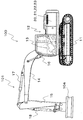
- FIG. 1 is a side view showing an example of an appearance of a work machine provided with an operation support apparatus according to the first embodiment of the present invention.
- a hydraulic excavator 100 includes a traveling body 11 having a left traveling body and a right traveling body, and a revolving body 12 that is turnably mounted on the traveling body 11, and a front portion of the revolving body 12.
- a cab 13 is attached to the vehicle.
- a work front 101 that is rotatable up and down is attached to the front portion of the revolving structure 12.
- a fuel tank 20, an engine 21, a main pump 22, a hydraulic oil tank 23, and the like are attached to the rear part of the revolving body 12.
- the work front 101 is attached to the swing body 12 so as to be pivotable up and down, an arm 15 attached to the boom 14 so as to be pivotable up and down, and attached to the arm 15 so as to be pivotable up and down.
- a work tool 102 is attached to the boom 14 so as to be pivotable up and down.
- the boom 14 is rotated in the vertical direction by a boom cylinder 16 connected to the revolving body 12 and the boom 14.
- the arm 15 is rotated in the vertical direction by an arm cylinder 17 connected to the boom 14 and the arm 15.
- the work tool 102 is rotated in the vertical direction by a work tool cylinder 18 connected to the arm 15 and the work tool 102.
- a boom angle sensor 14A provided in the vicinity of the connecting portion between the swing body 12 and the boom 14, and an arm angle sensor provided in the vicinity of the connecting portion between the boom 14 and the arm 15 are used.
- 15A and a work tool angle sensor 102A provided in the vicinity of the connecting portion between the arm 15 and the work tool 102.
- FIG. 2 shows an example of the control circuit of the work machine shown in FIG.
- the main pump 22 is driven by the engine 21.
- Fuel necessary for driving the engine 21 is supplied from the fuel tank 20.
- the fuel consumption at this time is measured by the fuel consumption measuring device 37.
- a boom lever operation amount measuring device 33a that measures the operation amount of the boom operation lever 30 as a voltage value
- an arm lever operation amount measuring device 33b that measures the operation amount of the arm operation lever 31 as a voltage value
- a work tool lever operation amount measuring device 33c that measures the operation amount of 32 as a voltage value.
- the drive direction and opening area of the control valves 24a, 24b, 24c are adjusted according to the voltage values measured by these lever operation amount measuring devices 33a-33c, and the pressure oil discharged from the main pump 22 is controlled by the control valves 24a, 24b, The fuel is supplied to the boom cylinder 16, the arm cylinder 17, and the work tool cylinder 18 through 24c.
- the boom cylinder 16 includes a pressure measuring device 34a for measuring the pressure on the bottom side in the boom cylinder 16 and a pressure measuring device 34b for measuring the pressure on the rod side.
- the arm cylinder 17 includes a pressure measuring device 35a for measuring the pressure on the bottom side in the arm cylinder 17 and a pressure measuring device 35b for measuring the pressure on the rod side.
- the work tool cylinder 18 includes a pressure measuring device 36a for measuring the pressure on the bottom side in the work tool cylinder 18 and a pressure measuring device 36b for measuring the pressure on the rod side.
- Measurement signals output from the various measuring instruments described above are input to the controller 200 and used for the operation of the operation support apparatus 201.
- the calculation result is displayed on the monitor device 303.
- the first measuring device for measuring the state value necessary for calculating the work amount of the excavator 100 is the boom angle sensor 14A, the arm angle sensor 15A, the work tool angle sensor 102A, the pressure measuring instrument 34a, and the pressure measurement. It is comprised by the device 34b.
- the second measuring device that measures a state value necessary for calculating the working time of the hydraulic excavator 100 includes a lever operation amount measuring device 33a, a lever operation amount measuring device 33b, and a lever operation amount measuring device 33c.
- the third measuring device that measures a state value necessary for calculating the fuel consumption (power consumption) of the excavator 100 is constituted by a fuel consumption measuring device 37.
- control valves 24a, 24b, and 24c are controlled by the controller 200 to valve positions (spool positions) corresponding to the operation amounts of the boom operation lever 30, the arm operation lever 31, and the work tool operation lever 32.
- FIG. 3 is a schematic diagram showing the arrangement of the operation levers.
- the right operation lever 38 shown in FIG. 3 also serves as the boom operation lever 30 and the work tool operation lever 32.
- the pressure oil having a flow rate corresponding to the operation amount is supplied to the bottom side oil chamber 16 a of the boom cylinder 16.
- pressure oil having a flow rate corresponding to the operation amount is supplied to the rod side oil chamber 16 b of the boom cylinder 16.
- the pressure oil at a flow rate corresponding to the operation amount is supplied to the bottom side oil chamber 18 a of the work tool cylinder 18.
- pressure oil having a flow rate corresponding to the operation amount is supplied to the rod side oil chamber 18b of the work tool cylinder 18.
- the left operation lever 39 shown in FIG. 3 also serves as the arm operation lever 31 and the turning operation lever.
- pressure oil having a flow rate corresponding to the operation amount is supplied to the bottom-side oil chamber 17 a of the arm cylinder 17.
- pressure oil having a flow rate corresponding to the operation amount is supplied to the rod-side oil chamber 17 b of the arm cylinder 17.
- the turning body 12 is assigned to the turning operation with respect to the traveling body 11.
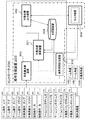
- FIG. 4 shows the configuration of the operation support apparatus 201 for the work machine in the present embodiment.
- signals 40 to 47 which are input to the operation support device 201 in the controller 200 are the lever operation amounts of the right operation lever 38 and the left operation lever 39 measured by the lever operation amount measuring devices 33a, 33b, 33c and the like.
- Signals 70 to 75 are pressure signals on the bottom side and the rod side of each cylinder measured by the pressure measuring devices 34a, 34b, 35a, 35b, 36a, 36b of the boom cylinder 16, the arm cylinder 17, and the work implement cylinder 18. is there.
- a signal 90 is a fuel consumption signal measured by the fuel consumption measuring device 37.
- Signals 14B, 15B, and 102B are angle detection signals of the angle sensors 14A, 15A, and 102A for obtaining the posture of the work front 101.
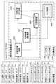
- the work machine operation support device 201 includes a state quantity calculation device 300, a work result calculation device 301, a work result output device 302, a monitor device 303, and a main storage device 304.
- the state quantity calculation device 300 includes a boom angle sensor 14A, an arm angle sensor 15A, a work tool angle sensor 102A, pressure measuring devices 34a, 34b, 35a, 35b, 36a, 36b, lever operation amount measuring devices 33a, 33b, 33c, and fuel.
- the above-mentioned signals (state values) measured by the consumption meter 37 are acquired, and the state quantities of the work amount, work time, and fuel consumption amount are calculated based on the values of the signals. Further, the calculated amount of work, work time, and fuel consumption are output to the main storage device 304.
- the main storage device 304 stores each state quantity calculated by the state quantity calculation device 300 and work results calculated by the work result calculation device 301 described later. In addition, the stored work results and each state quantity are output in response to the request of the work result calculation device 301.
- the work result calculation device 301 calculates a work result representing work efficiency based on the work amount, the work time, and the fuel consumption amount calculated by the state amount calculation device 300.
- the calculated work results are output to the main storage device 304 and the work result output device 302.
- the work result output device 302 outputs the work result calculated by the work result calculation device 301 to the monitor device 303. In addition to the work results, the work result output device 302 outputs the work amount, work time, and fuel consumption used at the time of the work result calculation to the monitor device 303.
- the monitor device 303 is provided inside the cab 13 of the excavator 100, and displays the work results output by the work result output device 302. In addition to the work results, the monitor device 303 displays the state quantities of work amount, work time, and fuel consumption.
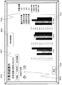
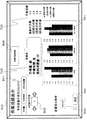
- FIG. 5 shows an example of a display screen of the monitor device 303 in this embodiment.
- the display screen of the monitor device 303 includes a work result calculation switch 800, a work result display area 700 for displaying work results, a state quantity display area 701 for displaying each measured state quantity, and a setting for setting display.
- the number of operations is the number of times the operation result calculation switch 800 is pressed. For example, when 3 is input to the past work result display setting area 802, the past three work results are displayed in the work result display area 700 from the work results calculated by the work result calculation device 301.
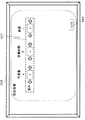
- FIG. 6 shows an example of a setting display screen displayed when the setting switch 704 of the monitor device 303 in this embodiment is pressed.
- the setting display screen includes a weight setting area 807 for setting the weight of each state quantity used in the work performance calculation device 301, and a return switch 820 that returns to the display screen of FIG. 5 when pressed. .
- the calculation processing of the state quantity calculation device 300 shown in FIG. 7 is executed at a preset sampling time from the start to the stop of the engine 21, and the work amount, fuel consumption, work time (operation lever at each time) 38, 39 is output).
- the state quantity computing device 300 uses the relations shown in FIGS. 8A to 8C to operate lever operation amount signals 40 to 47, cylinder pressure signals 70 to 75, fuel consumption amount signal 90, and angle sensor detection signals.
- Each signal value (state value) of 14B, 15B, and 102B is converted into each physical quantity (step S500).
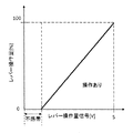
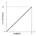
- the operation amounts of the boom operation lever 30, the arm operation lever 31, and the work tool operation lever 32 are calculated from the relationship between the lever operation amount signal and the lever operation amount as shown in FIG. 8A.
- the cylinder pressures of the boom cylinder 16, the arm cylinder 17, and the work tool cylinder 18 are calculated from the relationship between the pressure signal of each cylinder and the cylinder pressure as shown in FIG. 8B.
- the fuel consumption required to drive the engine 21 is calculated from the relationship between the fuel consumption signal and the fuel consumption as shown in FIG. 8C.
- step S501 the operation amount of each operation lever is read.
- Step S502 it is determined whether or not any one of the lever operation amount signals read in the previous step S501 is greater than or equal to a preset dead zone (see FIG. 8A).
- Step S502 When it is determined that any lever operation amount is equal to or greater than the dead zone, “operation is performed” is identified, and the process proceeds to step S503. On the other hand, when it is determined that any lever operation amount is less than the dead zone, the process proceeds to step S506.
- step S502 If it is determined that “operation is present” in step S502, it is then determined whether or not the lever operation amount one sample before is “operation is present” (step S503). When it is determined that the lever operation amount one sample before is “operated”, the process proceeds to step S504, and when it is determined “no operation”, the process proceeds to step S506.
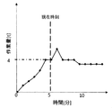
- step S503 If it is determined in step S503 that the lever operation amount one sample before is “with operation”, then the number of times “with operation” is added (step S504). Thereafter, the product of the number of times “operation is performed” and the sampling time are calculated (step S505). This calculation result becomes the working time at each time. For example, if the sampling time is 1 minute and the time after engine start is 5 minutes, as shown in FIG. 9A, the lever operation amount at that time (indicated as current time in FIG. 9A) and the lever operation amount one sample before Is “operated” three times.
- the posture of the work front 101 is calculated from the measurement signals measured by the boom angle sensor 14A, the arm angle sensor 15A, and the work tool angle sensor 102A. Further, the load applied to the work tool 102 is calculated from the calculated posture of the work front 101 and the pressure signal of the boom cylinder 16 converted in step S500.
- the calculated load is set as a work amount at each time (step S506). For example, in the case of 5 minutes after the engine is started, the work amount is as shown in FIG. 9B (displayed as current time).
- the calculation of the posture in step S506 may be performed, for example, at a timing when a work amount measurement switch (not shown) is pressed, or at any timing other than the sampling time, for example, every predetermined time. You may make it do.
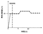
- step S500 the fuel consumption converted from the fuel consumption signal in step S500 is regarded as the fuel consumption at each time (step S507). In the case of 5 minutes after the engine is started, it becomes as shown in FIG. 9C (displayed as current time).
- step S508 the state quantities of the work time obtained in step S505, the work amount obtained in step S506, and the fuel consumption obtained in step S507 are output to the main storage device 304 (step S508).
- the work performance calculation device 301 determines whether or not the work performance calculation switch 800 as shown in FIG. 5 has been pressed (step S510). If it is determined that the button has been pressed, the process proceeds to step S511. If it is determined that the button has not been pressed, the process ends.
- each state quantity for a preset time from the past to the present (for example, 5 minutes) is acquired from the main storage device 304 (step S511).
- Each state quantity acquired from the main storage device 304 is a preset time from the past to the present, but it is specified by the number of operations as from the previous operation to this time instead of the time specification, and for the specified period. You may make it acquire the state quantity of time.
- step S512 a time average value of the work amount and the fuel consumption amount is calculated (step S512).
- each state quantity used when calculating the work performance is normalized with a preset value (for example, work quantity, work time, fuel consumption obtained in the same work in the past) to be a value from 0 to 1. Turn into.
- ⁇ , ⁇ , and ⁇ in Expression 1 are the weights set in the weight setting area 807 on the setting screen in FIG. 6 displayed when the setting switch 704 in FIG. 5 is pressed, and can be arbitrarily changed. Value.
- step S5 the calculated work result and each state quantity used at the time of the work result calculation are stored in the main storage device 304. Thereafter, a signal is sent to the work result output device 302 indicating that the calculation has been completed (step S516).
- the work results are calculated on the premise that the larger the work amount, the lower the work time and the fuel consumption, the more efficient, the work time and the fuel consumption are calculated as reciprocal numbers.
- the work results can be calculated using either a real number or an inverse number according to the preconditions.
- the work amount and the fuel consumption amount among the state quantities used at the time of calculating the work results are the average values per time from the past to the present, and the maximum value and the minimum value therebetween. You may make it calculate work results using.
- work performance is calculated by adding each state quantity, it may be calculated by multiplication.
- the work result output device 302 determines whether or not a calculation end signal has been received from the work result calculation device 301 as shown in FIG. 5 (step S520). If it is determined that the button has been pressed, the process proceeds to step S521. If it is determined that the button has not been pressed, the process ends.
- step S520 If it is determined in step S520 that the work result calculation switch 800 has been pressed, the work results calculated by the work result calculation device 301 and the state quantities used in the work result calculation calculated by the state amount calculation device 300 are stored in the main memory. Reading from the device 304 (step S521).
- step S522 the state quantity to be displayed is determined by the state quantity display selection area 801 in FIG. 5 (step S522).
- step S523 the past work results according to the values input in the work result display setting area 802 and the state quantities determined in step S522 are read from the main storage device 304 (step S523). ).
- step S521 and step S523 and the state quantities are combined and output to the monitor device 303 (step S524).
- the monitor device 303 displays the work results in the work result display area 700 according to the display screen of FIG. 5, and displays each state quantity used in the work result calculation in the state quantity display area 701.
- the horizontal axis of the graph of each state quantity in the state quantity display area 701 of the present embodiment is the number of operations, and the vertical axis is each normalized state quantity.
- the processing by the work result output device 302 is executed by receiving the calculation end signal from the work result calculation device 301.
- another switch for outputting work results is provided, and the signal from this switch is The processing may be executed by receiving.
- ⁇ Summary of this example> In the work machine operation support apparatus of the present embodiment configured and operated as described above, when the work result calculation switch 800 is pressed for the work performed by the excavator 100, a preset time (for example, The average value per hour of the amount of work and the amount of fuel consumption in 5 minutes) and the respective state quantities in between are obtained, and the work results are calculated from these state quantities. The work result calculated on that and each state quantity used at the time of work result calculation are displayed.
- a preset time for example, The average value per hour of the amount of work and the amount of fuel consumption in 5 minutes
- each state quantity, past work results, and each state quantity used when calculating the work results are displayed together, so that the operator can improve his work efficiency and skill level. Can be confirmed, and further improvement in work efficiency and skill level can be expected.
- 5 and 6 are display screens assuming a touch panel, but a similar display can be realized even with a normal monitor device.
- the display screen of the monitor device 303 is the mode shown in FIG. 5 and FIG. 6, but the arrangement of the areas is not limited to this. Further, the type of area to be displayed is not limited to these.
- the work machine operation support apparatus of the present embodiment has substantially the same configuration as the work machine operation support apparatus of the first embodiment described above, except for the contents described below, and details thereof are omitted.
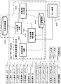
- FIG. 12 shows the configuration of the work machine operation support apparatus 202 in the present embodiment. The difference from FIG. 4 is that an influence degree computing device 305 is added.
- an influence degree calculation device 305 is a device that calculates an influence degree that indicates the relative influence degree of each state quantity on the work results, and each state quantity used in the work result calculation and the work result calculation apparatus 301.
- the degree of influence is calculated from the calculated work results by a calculation method described later.
- the work result output device 302 outputs the influence of the work amount, work time, and fuel consumption on the work result calculated by the influence degree calculation device 305 to the monitor device 303.
- the influence calculation device 305 determines whether or not a signal indicating that the calculation is completed is received from the work performance calculation device 301 (step S529). If not received, the process ends. If received, the process proceeds to the next step S530. In the next step S530, the work result and each state quantity calculated by the work result calculation device 301 are acquired from the main storage device 304 (step S530).
- step S531 the degree of influence of each state quantity on the work result is calculated from the work result and each state quantity used when calculating the work result by the calculation methods shown in the following formulas 2 to 4 (step S531).
- the degree of influence calculated as above is evaluated as “good” because the influence degree of the working time is the largest, “bad” because the influence degree of the work amount is next smallest, and the fuel consumption amount is evaluated as “medium”. .
- step S532 the evaluation result of the degree of influence obtained in step S532 is output to the work result output device 302 (step S533).
- the work result output device 302 in the present embodiment outputs the above-described influence degree evaluation results to the monitor device 303.
- FIG. 5 An example of the display of the monitor device 303 in this embodiment is shown in FIG. The difference from FIG. 5 is that an influence display section 702 and an influence display selection section 803 are added.
- Whether or not to display the evaluation result of the influence degree on the influence degree display part 702 is determined by the selection of the influence degree display selection part 803.
- the second embodiment of the work machine operation support apparatus according to the present invention can provide substantially the same effect as the first embodiment of the work machine operation support apparatus described above.
- the work amount contributed less to the work result than the fuel consumption amount and the work time. That is.
- devising to increase the amount of work such as increasing the amount of excavated soil per time more than before, improving work results than shortening work time and improving fuel consumption It is expected to be effective to do so. That is, the operator can grasp which state quantity is improved to improve the work result, and as a result, work efficiency can be improved, and the skill level of the operator can be improved.
- the degree of influence in this embodiment is a relative index indicating which index of work amount, work time, and fuel consumption is better than other indices, and the balance of these three indices is well balanced. It is an index to do. Therefore, when all of the work amount, the work time, and the fuel consumption amount are bad on average, the work result is bad, and the influence degree of each state quantity is displayed so that there is almost no difference. In this case, it will be understood that overall improvement of the work amount, work time, and fuel consumption is necessary. Also, if the amount of work and the working time are very good, but the fuel consumption is average, the work result is good and the influence level indicates that the fuel consumption is bad. You can see at a glance that you should focus on improving the quantity.
- the evaluation result of the influence degree of each state quantity when displayed, it is displayed as “good / medium / bad”, but the display example is not limited to this. For example, it can be displayed as “Large, Medium, Small”, “First, Second, Third”, and the calculated influence can be displayed numerically.
- the display form is arbitrary as long as the degree can be relatively determined.
- the work machine operation support apparatus of the present embodiment has substantially the same configuration as the work machine operation support apparatus of the first embodiment described above, except for the contents described below, and details thereof are omitted.
- FIG. 15 shows the configuration of the work machine operation support apparatus 203 in this embodiment. The difference from FIG. 4 is that a calculation period setting device 306 is added.
- a calculation period setting device 306 is a device for setting a period during which the state quantity calculation device 300 calculates each state quantity for work within a period set by a method described later.
- the state quantity computing device 300 obtains each state quantity during the reference period set by the computation period setting device 306.
- FIG. 5 An example of a display screen of the monitor device 303 in the present embodiment is shown in FIG. The difference from FIG. 5 is that a calculation period selection unit 804 is added in the display screen.
- the work performance calculation device 301 described above is in accordance with the calculation period (1 minute, 1 hour, 1 day, 1 month) selected by the calculation period selection unit 804 that selects the calculation period. Sets the period for obtaining each state quantity used when calculating work results.
- 1 minute, 1 hour, 1 day, and 1 month are shown as options.
- the setting period options are not limited to this, and the period can be set arbitrarily.
- the work performance calculation device 301 determines whether or not the work performance calculation switch 800 as shown in FIG. 5 has been pressed (step S540). If it is determined that the button has been pressed, the process proceeds to step S541. If it is determined that the button has not been pressed, the process ends.
- step S540 When it is determined in step S540 that the work performance calculation switch 800 has been pressed, the calculation period set by the calculation period setting device 306 is read (step S541).
- step S542 each state quantity of the work performed within the calculation period read in step S541 is acquired (step S542).
- step S542 using each state quantity acquired in step S542, the respective state quantities and work results are calculated in the same procedure as shown in steps S512 to S515 in FIG. 10 of the first embodiment, and the calculated work results and Each state quantity used at the time of work result calculation is stored in the main storage device 304 (step S546). Thereafter, a signal indicating that the calculation is completed is output to the work result output device 302 (step S547).
- the third embodiment of the work machine operation support apparatus of the present invention can provide substantially the same effect as the first embodiment of the work machine operation support apparatus described above.
- the work machine operation support apparatus of the present embodiment has substantially the same configuration as the work machine operation support apparatus of the first embodiment described above, except for the contents described below, and details thereof are omitted.
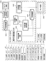
- FIG. 18 shows the configuration of the work machine operation support apparatus 204 in the present embodiment. The difference from FIG. 4 is that an external communication device 310 for communicating with the external storage device 900 is added.
- the external communication device 310 uses the work amount, work time, and fuel consumption state quantities used by the work result calculation device 301 when calculating the work result, and the calculated work results as a hydraulic excavator 100. And a function for receiving from the external storage device 900 the operation results of the operator of the other machine and each state quantity used when calculating the work results. Communication with the external storage device 900 is performed using the method. A known method can be used for communication between the external communication device 310 and the external storage device 900.
- the external storage device 900 stores the work results, work amount, work time, and fuel consumption amount transmitted from the external communication device 310 for each work machine.
- FIG. 5 An example of a display screen of the monitor device 303 in the present embodiment is shown in FIG.
- the difference from FIG. 5 is that a comparison / selection switch 810 with the operator of the other machine is added in the display screen, the work results of the operator of the other machine in the work result display area 700 and the state quantity display area 701, Each state quantity used at the time of calculating the work results is displayed together with its own work results and each state quantity used at the time of calculating the work results.
- the work result output device 302 displays the work results of other operators stored in the external storage device 900 via the external communication device 310 and the work results. Receives each state quantity used in the calculation.
- the work result output device 302 displays, in addition to its own work results and the respective state quantities used when calculating the work results, the received operator's work results and other state quantities used when calculating the work results. 19 are displayed in the work result display area 700 and the state quantity display area 701, respectively.
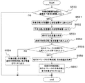
- step S552 transmits the work results and the respective state quantities to the external storage device 900
- step S555 for determining whether or not the comparison selection switch 810 with the operator of the other machine has been pressed
- Step S556 for receiving the operator's work results and the respective state quantities used in the calculation of the work results
- step S557 for outputting the own work results and the work results of the operator of the other machine to the monitor device 303 are added. is there.
- the work performance output device 302 first determines whether or not a signal indicating that the computation has been completed is received from the work performance computation device 301 (step S550). If it is determined that it has been received, the process proceeds to step S551. If it is determined that it has not been received, the process ends.
- step S550 If it is determined in step S550 that the work performance calculation switch 800 has been pressed, the work performance output device 302 reads the calculated work performance and each state quantity used in the work performance calculation from the main storage device 304 (step S551). .
- the calculated work result and each state quantity used when calculating the work result are output to the external storage device 900 via the external communication device 310 (step S552).
- the external storage device 900 stores the calculated work results and each state quantity used at the time of the work result calculation for each work machine.
- the state quantity to be displayed is determined from the ON / OFF state of each state quantity in the state quantity display selection area 801 shown in FIG. 20 (step S553).
- Step S554 the past work results according to the values input in the past work result display setting area 802 and the past work quantities used in the work result calculation are read from the main memory 304 according to step S553.
- step S555 it is determined whether or not the comparison / selection switch 810 with the operator of the other machine has been pressed. If it is determined that the comparison selection switch 810 has been pressed, the process proceeds to step S556. If it is determined that the comparison selection switch 810 has not been pressed, the process proceeds to step S559.
- step S556 the preset work results of the operator of the other machine and the respective state quantities used when calculating the work results are received from the external storage device 900 via the external communication device 310.
- step S524 of the work result output device 302 of the first embodiment shown in FIG. 11 and the respective state quantities used in the work result calculation are used as the past work results and the past work results calculation.
- the used state quantities are combined and output to the monitor device 303, and the operation results of the operator of the other machine and the state quantities used when calculating the work results are output to the monitor device 303 (step S557).
- step S555 determines whether the comparison selection switch 810 with the operator of the other machine has been pressed.
- step S524 of the work result output apparatus 302 of the first embodiment shown in FIG. the work result and each state quantity used at the time of calculating the work result and the past work result and each state quantity used at the time of calculating the past work result are output to the monitor device 303 (step S559).
- the fourth embodiment of the work machine operation support apparatus according to the present invention can provide substantially the same effect as the first embodiment of the work machine operation support apparatus described above.
- the work machine operation support apparatus of the present embodiment has substantially the same configuration as the work machine operation support apparatus of the fourth embodiment described above, except for the contents described below, and details thereof are omitted.
- FIG. 21 shows the configuration of the operation support device 205 for the work machine in this embodiment.
- the difference between FIG. 21 and FIG. 18 is that a work result comparison device 901 for creating a report for comparing the work results of each operator and a monitor device 709 for displaying a report for comparing the work results of each operator are added. is there.
- the external storage device 900 stores the work results, work amount, work time, and fuel consumption amount transmitted from the external communication device 310 for each work machine.
- the work result comparison device 901 compares the work results for each work machine stored in the external storage device 900, and ranks the work results of each work machine, such as which work machine is superior, Create a report.
- the monitor device 709 displays a report of comparison results of each work machine compared by the work performance comparison device 901.
- FIG. 22 shows an example of a report displayed on the monitor device 709 in this embodiment.
- a display area 710 the work results from the number of times of the preset operation of the selected operator to the immediately preceding work and the operators of other machines set in advance (for example, the highest-ranking operator and the reference operator) are displayed. Display work results numerically.
- each state quantity used when calculating the above-mentioned work results is displayed.
- the work results stored in the external storage device 900 are compared with the work results of the selected operator to display the ranking of the work results of the selected operator to be calculated.
- the fifth embodiment of the work machine operation support apparatus according to the present invention can provide substantially the same effects as the first embodiment of the work machine operation support apparatus described above.
- an operator selected by an administrator stationed outside the work machine for example, a management station or an office
- the work results, the respective state quantities used when the work results are calculated, and the ranking of the operator's work results can be confirmed.
- the work results of each work machine can be managed in an integrated manner, and this report can be fed back to each operator to contribute to the improvement of work results in the entire site where the work machine operates.
- the operator can receive his / her work results as a report at the end of the work, and even if the work results are not confirmed on the work machine, the operator can be notified of the work results, so that the operator can be more sure. It is possible to promote improvement of work performance.
- the work result comparison device 901 compares the state quantities used for the calculation of work results for each work machine in addition to the work results for each work machine stored in the external storage device 900. State quantity ranking can be performed.
- the work machine operation support apparatus of the present embodiment has substantially the same configuration as the work machine operation support apparatus of the first embodiment described above, except for the contents described below, and details thereof are omitted.
- FIG. 23 shows a display example of the setting screen when the setting switch 704 in FIG. 5 is pressed.
- FIG. 23 differs from FIG. 6 in that a calculation method selection unit 806 and a target value setting area 811 are added.
- the operator selects the calculation method of the calculation method selection unit 806 as having a target value, and sets the target value for each state quantity in the target value setting area 811. .
- the work result calculation device 301 is a work that represents work efficiency based on the work amount, the work time, and the fuel consumption amount calculated by the state amount calculation device 300.
- the calculation is performed by normalizing the target value set in the target value setting area 811 and outputting the result to the main storage device 304 and the work result output device 302.
- Step S564 output to 302 and step S565 for normalizing each state quantity with the target value of each state quantity are added.
- the work performance calculation device 301 determines whether or not the work performance calculation switch 800 as shown in FIG. 5 has been pressed (step S560). If it is determined that the button has been pressed, the process proceeds to step S561. If it is determined that the button has not been pressed, the process ends.
- step S560 If it is determined in step S560 that the work performance calculation switch 800 has been pressed, each state quantity for a preset time (for example, 5 minutes) from the past to the present is acquired from the main storage device 304 (step S561).
- a preset time for example, 5 minutes
- step S562 the time average value of the work amount and the fuel consumption amount is calculated (step S562).
- step S563 it is determined whether the calculation method selection unit 806 shown in FIG. 23 is selected as having no target value (1) or having a target value (2) (step S563).
- the target value is transmitted to the work result output device 302 (step S564).
- the time average value of the work amount and the fuel consumption calculated in step S562 and the work time acquired in step S561 are normalized by the target value of each state amount input in the target value setting area 811 of FIG. (Step S565).
- the work amount can be calculated as in the following equation 8.
- step S565 using each state quantity normalized in step S565, the work result is calculated using the above-described equation 1 in the same manner as in step S514 of the first embodiment (step S566).
- step S567 the calculated work result and each state quantity used at the time of the work result calculation are stored in the main storage device 304 (step S567). Thereafter, a signal is sent to the work result output device 302 to notify the completion of the calculation (step S568).
- step S563 When it is determined in step S563 that “no target value (1)” is selected, the time average value of the work amount and the fuel consumption calculated in step S562 is normalized (step S568), and then step S568 is performed. Using each state quantity normalized in step 1, the work result is calculated using the above-described equation 1 in the same manner as step S514 in the first embodiment (step S566).
- FIG. 25 An example of processing performed by the work result output device 302 in this embodiment is shown in FIG. 25 as a flowchart.
- the difference from FIG. 11 is that, when a calculation end signal is received from the work performance calculation device 301, the calculation method selected by the calculation method selection unit 806 is determined in step S571, and the target is set according to the calculation method selection unit 806.
- Step S572 is added in which the target value input to the value setting area 811, the calculated work result, and each state quantity used in the work result calculation are read from the main storage device 304.
- the work performance output device 302 determines whether or not an operation end signal has been received from the work performance calculation device 301 as shown in FIG. 5 (step S570). If it is determined that it has been received, the process proceeds to step S571. If it is determined that it has not been received, the process ends.
- step S570 If it is determined in step S570 that the work performance calculation switch 800 has received, it is determined whether the calculation method selection unit 806 shown in FIG. 23 is selected as having no target value (1) or having a target value (2). Determination is made (step S571).
- step S572 When it is determined that the work result calculation method “with target value (2)” has been selected, the target value input in the target value setting area 811, the calculated work result, and each state quantity used in the work result calculation And output to the main memory 304 (step S572).
- the state quantity to be displayed is determined from the state quantity ON / OFF state of the state quantity display selection area 801 in FIG. 5 (step S573), and the past according to the value input in the past work result display setting area 802 is determined. And the past state quantities used for the work result calculation are read from the main memory 304 (step S574). Thereafter, the calculated work result and each state quantity used at the time of the work result calculation are combined with the past work result and each state quantity used at the time of the past work result calculation, and output to the monitor device 303 (step S575).
- the monitor device 303 displays the work results in the work result display area 700 according to the display screen of FIG. 5, and displays each state quantity used in the work result calculation in the state quantity display area 701.
- step S571 If it is determined in step S571 that “no target value (1)” has been selected, the calculated work results and the state quantities used in the work result calculation are output to the main storage device 304 (step S576). Then, the process proceeds to step S573.
- the sixth embodiment of the work machine operation support apparatus according to the present invention can provide substantially the same effect as the first embodiment of the work machine operation support apparatus described above.
- the posture of the work front 101 (the angles of the boom 14, the arm 15, and the work tool 102) is set to the boom angle sensor 14A, the arm angle sensor 15A, and the work tool angle sensor 102A.
- the amount of work is calculated by calculating from the measured signal and comparing the posture and the pressure signal of the boom cylinder 16, but the calculation method is arbitrary as long as the amount of work can be calculated.
- a load cell can be mounted on the work tool 102 mounting portion of the work front 101, and the work amount can be measured with the load cell.
- the posture of the work front 101 is calculated from stroke signals of stroke measuring instruments (not shown) of the respective cylinders 16 to 18, and the posture of the work front 101 is compared with the pressure signal of the boom cylinder 16 converted in step S500.
- the amount of work applied to the work tool 102 can be calculated.
- the work amount is measured when the work amount measurement switch is pressed.
- the structure is arbitrary as long as the work amount can be measured.
- the work amount can be measured in a preset posture.
- the work time is calculated from the lever operation amount signals 40 to 47, but the structure is arbitrary as long as the work time can be calculated.
- the camera is installed at a position where the work front 101 of the work machine can be measured, the camera is used to detect whether the front is moving, and the time during which the work front 101 is operating is measured as the work time. can do.
- the state quantity display method displayed in the state quantity display area 701 is the screen as shown in FIG. 5, FIG. 14, FIG. 16, or FIG. It is not limited.
- the state quantity such as a numerical value display, a scatter diagram, a radar chart, and a pie chart
- the display form can be arbitrarily selected.
- the work results are displayed numerically in the work result display area 700, display forms such as a scatter diagram, a radar chart, and a pie chart other than the numerical values are arbitrary.
- the work front 101 is provided with the work front 101 attached to the arm 15 as shown in FIG. 1 so as to be pivotable up and down.
- the work front 101 is not limited to this.
- the work front 101 may be configured to have at least one actuator, and the configuration thereof is arbitrary, such as the number of fronts, the number of front joints, and the type of work tool.
- the configuration of the operating device is the mode shown in FIG. 3, but the mode of the operating device is not limited to this.
- the operating device may be an operating device that can instruct driving of each actuator, and its geometric arrangement is also arbitrary. Further, an arbitrary configuration can be taken for the relationship between the operation shaft of the operation lever and the operation actuator of the work front.
- the power source is not limited to the engine, and an electric motor using a built-in battery or an external power source as a power source is used.
- the main pump can be driven.
- the power consumption is not “fuel consumption” but “power consumption”, and the power consumption is measured by the power consumption meter.
- the power consumption is the fuel consumption and the power consumption.
- the hydraulic excavator has been described as an example of the work machine.
- the work machine is not limited to the hydraulic excavator, and the present invention can be applied to work machines such as a wheel loader, a dump truck, and a bulldozer.
- An operation support device for a work machine can be applied.
- Work result output device 303: Monitor device, 304 ... main memory, 305 ... Influence level calculation device, 306 ... Calculation period setting device, 310 ... an external communication device, 700 ... work result display area, 701 ... state quantity display area, 702 ... Influence level display section, 704 ... Setting switch, 709 ... monitor device, 800 ... Work result calculation switch, 801 ... state quantity display selection area, 802 ... Past work results display setting area, 803 ... Influence display selection section, 804 ... Calculation period selection unit, 806: Calculation method selection unit, 807 ... Weight setting area, 810 ... Comparison selection switch, 811 ... Target value setting area, 820 ... Return switch, 900 ... an external storage device, 901 ... Work performance comparison device.
Landscapes
- Engineering & Computer Science (AREA)
- Mining & Mineral Resources (AREA)
- Civil Engineering (AREA)
- General Engineering & Computer Science (AREA)
- Structural Engineering (AREA)
- Mechanical Engineering (AREA)
- Component Parts Of Construction Machinery (AREA)
- Operation Control Of Excavators (AREA)
Abstract
燃料消費量だけではなく、作業時間や作業量を含むオペレータの作業効率・スキルレベルの向上を図ることができる作業機械の操作支援装置を提供する。 油圧ショベル100が行った作業に対して、作業成績演算スイッチ800が押下された場合に、あらかじめ設定された過去から現在までの時間(たとえば5分)における作業量と燃料消費量の時間平均値と作業時間を求めるとともに、これら各状態量から作業成績を演算する。その後、演算した作業成績と作業成績演算時に使用した各状態量を表示する。
Description
本発明は、解体作業や建築作業、土木作業等に使用される作業機械の操作を支援するための操作支援装置に係わる。
油圧ショベルやクレーンなどの作業機械は、様々な作業で使用できることが求められており、各種作業において効率的に作業を行うことが求められている。
従来では、例えば特許文献1のように、効率的な作業を行うために、省エネルギー化に観点を置き、燃料消費量の改善を促すガイダンスを表示する機能を備えた建設機械が知られている。
具体的には、特許文献1では、建設機械の運転状況に関する所定状態値の頻度分布に対する設定目標値を設定し、所定状態値を検出して、検出手段により検出された所定状態値の頻度分布を計算し、計算された頻度分布と設定手段により設定された設定目標値とを比較し、その比較結果に応じて、予め用意してあるメッセージを出力している。
上記特許文献1の記載によれば、特に燃料消費量の改善を促すメッセージを表示することによって作業機械の燃料消費量を改善するための効率の良い作業を行うことが可能になるとされている。
しかしながら、この特許文献1は燃料消費量を改善することが主な目的であり、その結果、作業時間が増加する、あるいは、作業量が減少するといった問題が起こり得る。
すなわち、特許文献1にはこれまでにオペレータが行った作業の効率を総合的に評価する手法が開示されておらず、オペレータは自らのスキルレベルを把握できない。このため、作業効率の良し悪し、スキルレベルの高低は、オペレータ自身の判断に依存し、作業効率、スキルレベルの向上という観点では必ずしもサポートされているとは言えない。
本発明は、燃料消費量だけではなく、作業時間や作業量を含むオペレータの作業効率・スキルレベルの向上を図ることができる作業機械の操作支援装置を提供することを目的とする。
上記目的を達成するために、本発明は、作業機械の操作支援装置であって、前記作業機械の作業量を演算するために必要な状態値を計測する第1計測装置と、前記作業機械の作業時間を演算するために必要な状態値を計測する第2計測装置と、前記作業機械の動力消費量を演算するために必要な状態値を計測する第3計測装置と、前記第1計測装置、前記第2計測装置および前記第3計測装置によって計測された各状態値に基づいて前記作業量、前記作業時間および前記動力消費量を演算する状態量演算装置と、この状態量演算装置で演算された前記作業量、前記作業時間および前記動力消費量に基づいて作業の効率を表す作業成績を演算する作業成績演算装置と、この作業成績演算装置で演算された前記作業成績を出力する作業成績出力装置とを備えたことを特徴とするものである。
かかる構成により、作業機械が使用される様々な作業において、作業量、作業時間、燃料消費量の各状態量から作業効率・スキルレベルを総合的に評価するための作業成績を演算し、オペレータに提示することが可能となる。この作業成績を参照することで、オペレータは自らの作業効率・スキルレベルを把握することができ、作業効率・スキルレベルの向上を図ることができる。
本発明によれば、オペレータは、燃料消費量だけでなく作業量や作業時間も考慮された自身の作業成績を把握することができ、作業効率・スキルレベルの向上を図ることができるようになる。
以下に本発明の作業機械の操作支援装置の実施例を、図面を用いて説明する。
<第1の実施例>
本発明の作業機械の操作支援装置の第1の実施例を、図1乃至図11を用いて説明する。なお、図1乃至図11においては、作業機械として油圧ショベルに適用した場合を例に挙げて説明する。
本発明の作業機械の操作支援装置の第1の実施例を、図1乃至図11を用いて説明する。なお、図1乃至図11においては、作業機械として油圧ショベルに適用した場合を例に挙げて説明する。
<全体構成>
図1は本発明の第1の実施例に係わる操作支援装置が備えられた作業機械の外観の一例を示す側面図である。
図1は本発明の第1の実施例に係わる操作支援装置が備えられた作業機械の外観の一例を示す側面図である。
図1において、油圧ショベル100は、左走行体及び右走行体を備えた走行体11と、走行体11上に旋回可能に取り付けられた旋回体12とを有し、その旋回体12の前部に運転室13が取り付けられている。また、旋回体12の前部には上下回動自在な作業フロント101が取り付けられている。旋回体12の後部には燃料タンク20、エンジン21、メインポンプ22、作動油タンク23等が取り付けられている。
<フロント構成>
作業フロント101は旋回体12に対して上下回動自在に取り付けられたブーム14と、このブーム14に上下回動自在に取り付けられたアーム15と、このアーム15に上下回動自在に取り付けられた作業具102とを備えている。このうち、ブーム14は、旋回体12とブーム14とに連結されたブームシリンダ16によって上下方向に回動される。アーム15は、ブーム14とアーム15とに連結されたアームシリンダ17によって上下方向に回動される。作業具102は、アーム15と作業具102とに連結された作業具シリンダ18によって上下方向に回動される。
作業フロント101は旋回体12に対して上下回動自在に取り付けられたブーム14と、このブーム14に上下回動自在に取り付けられたアーム15と、このアーム15に上下回動自在に取り付けられた作業具102とを備えている。このうち、ブーム14は、旋回体12とブーム14とに連結されたブームシリンダ16によって上下方向に回動される。アーム15は、ブーム14とアーム15とに連結されたアームシリンダ17によって上下方向に回動される。作業具102は、アーム15と作業具102とに連結された作業具シリンダ18によって上下方向に回動される。
また、作業フロント101の姿勢を算出するために、旋回体12とブーム14との連結部近傍に設けられたブーム角度センサ14A、ブーム14とアーム15との連結部近傍に設けられたアーム角度センサ15A及びアーム15と作業具102との連結部近傍に設けられた作業具角度センサ102Aを備えている。
<制御回路の基本構成>
図1の作業機械の制御回路の一例を図2示す。
図1の作業機械の制御回路の一例を図2示す。
図2の制御回路において、メインポンプ22はエンジン21により駆動される。燃料タンク20よりエンジン21を駆動するのに必要な燃料が供給される。このときの燃料消費量は燃料消費量計測器37にて計測される。
また、ブーム操作レバー30の操作量を電圧値として計測するブームレバー操作量計測器33aと、アーム操作レバー31の操作量を電圧値として計測するアームレバー操作量計測器33bと、作業具操作レバー32の操作量を電圧値として計測する作業具レバー操作量計測器33cとを備えている。これら各レバー操作量計測器33a~33cで計測された電圧値に従ってコントロール弁24a,24b,24cの駆動方向および開口面積が調整され、メインポンプ22から吐出された圧油がコントロール弁24a,24b,24cを経てブームシリンダ16,アームシリンダ17,作業具シリンダ18に対して各々供給される。
また、ブームシリンダ16は、ブームシリンダ16内のボトム側の圧力を計測する圧力計測器34a、ロッド側の圧力を計測する圧力計測器34bを備えている。同様に、アームシリンダ17は、アームシリンダ17内のボトム側の圧力を計測する圧力計測器35a、ロッド側の圧力を計測する圧力計測器35bを備えている。同様に、作業具シリンダ18は、作業具シリンダ18内のボトム側の圧力を計測する圧力計測器36a、ロッド側の圧力を計測する圧力計測器36bを備えている。
前述の各種計測器から出力された計測信号はコントローラ200に入力され、操作支援装置201の演算に使用される。この演算結果はモニタ装置303に表示される。このうち、油圧ショベル100の作業量を演算するために必要な状態値を計測する第1計測装置は、ブーム角度センサ14A,アーム角度センサ15A,作業具角度センサ102A,圧力計測器34a,圧力計測器34bによって構成される。また、油圧ショベル100の作業時間を演算するために必要な状態値を計測する第2計測装置は、レバー操作量計測器33a,レバー操作量計測器33b,レバー操作量計測器33cによって構成される。また、油圧ショベル100の燃料消費量(動力消費量)を演算するために必要な状態値を計測する第3計測装置は、燃料消費量計測器37によって構成される。
<シリンダ駆動>
図2において、ブームシリンダ16のボトム側油室16aへメインポンプ22から吐出された圧油が供給された場合には、ブーム14は旋回体12に対して上方向に回動駆動される。反対にロッド側油室16bにメインポンプ22から吐出された圧油が供給された場合には、ブーム14は旋回体12に対して下方向に回動駆動される。
図2において、ブームシリンダ16のボトム側油室16aへメインポンプ22から吐出された圧油が供給された場合には、ブーム14は旋回体12に対して上方向に回動駆動される。反対にロッド側油室16bにメインポンプ22から吐出された圧油が供給された場合には、ブーム14は旋回体12に対して下方向に回動駆動される。
アームシリンダ17のボトム側油室17aへ圧油が供給された場合には、アーム15はブーム14に対して下方向に回動駆動される。反対にロッド側油室17bに供給された場合には、アーム15はブーム14に対して上方向に回動駆動される。
作業具シリンダ18のボトム側油室18aへ圧油が供給された場合には、作業具102はアーム15に対して下方向に回動駆動される。反対にロッド側油室18bに供給された場合には、作業具102はアーム15に対して上方向に回動駆動される。
<操作系>
コントロール弁24a,24b,24cは、コントローラ200によって、ブーム操作レバー30、アーム操作レバー31、作業具操作レバー32の操作量に応じた弁位置(スプール位置)に制御される。
コントロール弁24a,24b,24cは、コントローラ200によって、ブーム操作レバー30、アーム操作レバー31、作業具操作レバー32の操作量に応じた弁位置(スプール位置)に制御される。
コントロール弁24a,24b,24cの制御に必要な、ブーム操作レバー30の操作量はレバー操作量計測器33a、アーム操作レバー31の操作量はレバー操作量計測器33b、作業具操作レバー32の操作量はレバー操作量計測器33cにて計測される。図3に各操作レバーの配置を表す模式図を示す。
図3に示す右操作レバー38は、ブーム操作レバー30および作業具操作レバー32を兼ねている。右操作レバー38が図3中30(a)の方向へ操作されると、操作量に応じた流量の圧油がブームシリンダ16のボトム側油室16aへ供給される。反対に、右操作レバー38が図3中30(b)の方向へ操作されると、操作量に応じた流量の圧油がブームシリンダ16のロッド側油室16bへ供給される。右操作レバー38が図3中32(a)の方向に操作されると、操作量に応じた流量の圧油が作業具シリンダ18のボトム側油室18aへ供給される。反対に、右操作レバー38が図3中32(b)の方向に操作されると、操作量に応じた流量の圧油が作業具シリンダ18のロッド側油室18bへ供給される。
図3に示す左操作レバー39は、アーム操作レバー31および旋回操作レバーを兼ねている。左操作レバー39が図3中31(a)の方向に操作されると、操作量に応じた流量の圧油がアームシリンダ17のボトム側油室17aへ供給される。反対に、左操作レバー39が図3中31(b)の方向に操作されると、操作量に応じた流量の圧油がアームシリンダ17のロッド側油室17bへ供給される。左操作レバー39の前後方向の操作については.旋回体12の走行体11に対する旋回動作に割り当てられている。左操作レバー39が図3中旋回右方向に操作されると旋回体12は走行体11に対して右方向に旋回し、左操作レバー39が図3中旋回左方向へ操作されると旋回体12は走行体11に対して左方向に旋回する。
<操作支援装置201の基本構成>
図4に、本実施例における作業機械の操作支援装置201の構成を示す。
図4に、本実施例における作業機械の操作支援装置201の構成を示す。
図4において、コントローラ200内の操作支援装置201の入力となる信号40~47は、レバー操作量計測器33a,33b,33c等で計測される右操作レバー38および左操作レバー39のレバー操作量信号である。また、信号70~75はブームシリンダ16、アームシリンダ17、作業具シリンダ18の圧力計測器34a,34b,35a,35b,36a,36bで計測される各シリンダのボトム側とロッド側の圧力信号である。また、信号90は燃料消費量計測器37で計測される燃料消費量信号である。また、信号14B,15B,102Bは、作業フロント101の姿勢を求めるための各角度センサ14A,15A,102Aの角度検出信号である。
図4に示すように、作業機械の操作支援装置201は、状態量演算装置300と、作業成績演算装置301と、作業成績出力装置302と、モニタ装置303と、主記憶装置304とで構成される。
状態量演算装置300は、ブーム角度センサ14A、アーム角度センサ15A、作業具角度センサ102A、圧力計測器34a,34b,35a,35b,36a,36b、レバー操作量計測器33a,33b,33cおよび燃料消費量計測器37によって計測された前述の各信号(状態値)を取得し、各信号の値に基づいて作業量、作業時間および燃料消費量の各状態量を演算する。また、演算した作業量、作業時間および燃料消費量の各状態量を主記憶装置304に出力する。
主記憶装置304は、状態量演算装置300で演算された各状態量と、後述する作業成績演算装置301で演算された作業成績とを記憶する。また、作業成績演算装置301の求めに応じて記憶している作業成績や各状態量を出力する。
作業成績演算装置301は、状態量演算装置300で演算された作業量、作業時間および燃料消費量の各状態量に基づいて作業の効率を表す作業成績を演算する。演算した作業成績は、主記憶装置304や作業成績出力装置302に対して出力する。
作業成績出力装置302は、作業成績演算装置301で演算された作業成績をモニタ装置303に対して出力する。また、作業成績出力装置302は、作業成績に加えて、作業成績演算時に使用した作業量、作業時間、燃料消費量をモニタ装置303に対して出力する。
モニタ装置303は、油圧ショベル100の運転室13内部に設けられており、作業成績出力装置302の出力した作業成績を表示する。また、モニタ装置303は、作業成績に加えて、作業量、作業時間、燃料消費量の各状態量を表示する。
<モニタ装置の画面構成>
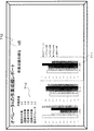
図5に、本実施例におけるモニタ装置303の表示画面の一例を示す。
図5に、本実施例におけるモニタ装置303の表示画面の一例を示す。
図5において、モニタ装置303の表示画面は、作業成績演算スイッチ800と作業成績を表示する作業成績表示領域700と計測した各状態量とを表示する状態量表示領域701と、表示設定をする設定スイッチ704と、各状態量を表示するか否かを選択する状態量表示選択領域801と、作業成績演算装置301で演算した作業成績と合わせて表示したい過去の作業成績の作業回数を指定する過去の作業成績表示設定領域802とで構成される。
なお、本実施例において、作業回数は、作業成績演算スイッチ800の押下回数である。また、例えば、過去の作業成績表示設定領域802に3が入力された場合、作業成績演算装置301で演算した作業成績から過去3回分の作業成績が作業成績表示領域700に表示される。
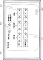
また、本実施例におけるモニタ装置303の設定スイッチ704が押下された場合に表示される設定表示画面の一例を図6に示す。
図6において、設定表示画面は、作業成績演算装置301で使用する各状態量の重みを設定する重み設定領域807と、押下することで図5の表示画面に戻る復帰スイッチ820で構成されている。
次に、本実施例における作業機械の操作支援装置201の動作を、状態量演算装置300、作業成績演算装置301および作業成績出力装置302の各部を参照して説明する。
<状態量演算装置の処理動作>
まず、状態量演算装置300が行う演算処理の一例について図7に示すフローチャートを用いて説明する。
まず、状態量演算装置300が行う演算処理の一例について図7に示すフローチャートを用いて説明する。
図7に示す状態量演算装置300の演算処理は、エンジン21の始動時から停止時まで、あらかじめ設定されたサンプリングタイムで実行され、各時刻における、作業量、燃料消費量、作業時間(操作レバー38,39が操作された時間の総和)を出力する。
まず、状態量演算装置300は、図8A乃至図8Cに示す各関係を用いて、レバー操作量信号40~47、各シリンダの圧力信号70~75、燃料消費量信号90および各角度センサ検出信号14B,15B,102Bの各信号値(状態値)を各々の物理量に変換する(ステップS500)。
例えば、図8Aに示すようなレバー操作量信号とレバー操作量との関係から、ブーム操作レバー30、アーム操作レバー31、作業具操作レバー32の各々の操作量を演算する。また、図8Bに示すような各シリンダの圧力信号とシリンダ圧力との関係から、ブームシリンダ16、アームシリンダ17、作業具シリンダ18のシリンダ圧力を演算する。また、図8Cに示すような燃料消費量信号と燃料消費量との関係から、エンジン21を駆動するのに要した燃料の消費量を演算する。
次に、各操作レバーの操作量を読み込む(ステップS501)。
次に、図8Aに示すように、先のステップS501において読み込んだ各操作レバーの操作量のうち、何れか一つのレバー操作量信号があらかじめ設定された不感帯以上であるか否かを判定する(ステップS502)。そして、何れかのレバー操作量が不感帯以上と判定されるときには「操作あり」と識別し、ステップS503に処理を進める。これに対し、何れのレバー操作量も不感帯未満であると判定されるときは、ステップS506に処理を進める。
ステップS502において「操作あり」と判定された場合は、次いで、1サンプル前のレバー操作量が「操作あり」か否かを判定する(ステップS503)。1サンプル前のレバー操作量が「操作あり」と判定されるときはステップS504に処理を進め、「操作なし」と判定されるときはステップS506に処理を進める。
ステップS503において1サンプル前のレバー操作量が「操作あり」と判定された場合は、次いで、「操作あり」となる回数を加算する(ステップS504)。その後、この「操作あり」となる回数とサンプリングタイムの積を演算する(ステップS505)。この演算結果が各時刻の作業時間となる。例えば、サンプリングタイムが1分で、エンジン始動後の時刻が5分の場合、図9Aに示すようにその時点(図9Aでは現在時刻と表示)でのレバー操作量と1サンプル前のレバー操作量が「操作あり」となる回数が3回である。
次に、例えば特開2012-103029号公報に記載されたように、ブーム角度センサ14A、アーム角度センサ15Aおよび作業具角度センサ102Aにて計測された計測信号から作業フロント101の姿勢を演算する。また、この演算された作業フロント101の姿勢と、ステップS500で変換したブームシリンダ16の圧力信号とから作業具102にかかる荷重を演算する。この演算した荷重を各時刻の作業量とする(ステップS506)。例えば、エンジン始動後5分の場合、作業量は図9B(現在時刻と表示)のようになる。なお、このステップS506における姿勢の演算は、例えば不図示の作業量計測スイッチが押下されたタイミングで行われるようにしても良いし、サンプリングタイムとは別の任意のタイミング、例えば所定時間経過ごとに行うようにしても良い。
次に、ステップS500において燃料消費量信号から変換した燃料消費量を、各時刻の燃料消費量とみなす(ステップS507)。エンジン始動後5分の場合、図9C(現在時刻と表示)のようになる。
次に、ステップS505で求めた作業時間、ステップS506で求めた作業量、ステップS507で求めた燃料消費量の各状態量を主記憶装置304に出力する(ステップS508)。
<作業成績演算装置の処理動作>
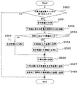
次に、本実施例における作業成績演算装置301の演算処理を図10に示すフローチャートを用いて説明する。
次に、本実施例における作業成績演算装置301の演算処理を図10に示すフローチャートを用いて説明する。
まず、作業成績演算装置301は、図5に示すような作業成績演算スイッチ800が押下されたか否かを判定する(ステップS510)。押下されたと判定されるときはステップS511に処理を進め、押下されていないと判定されるときは処理を終了する。
ステップS510において作業成績演算スイッチ800が押下されたと判定された場合、あらかじめ設定された過去から現在までの時間(例えば5分)における各状態量を主記憶装置304から取得する(ステップS511)。なお、主記憶装置304から取得する各状態量はあらかじめ設定された過去から現在までの時間としているが、時間指定ではなく前回の作業から今回までのように作業回数で指定し、その指定期間の時間の状態量を取得するようにしても良い。
次に、ステップS511で取得した各状態量のうち、作業量と燃料消費量の時間平均値を演算する(ステップS512)。
次に、ステップS511で取得した作業時間、ステップS512で演算した作業量および燃料消費量の時間平均値を正規化する(ステップS513)。本実施例においては、作業成績演算時に使用する各状態量は0から1の値になるようにあらかじめ設定した値(たとえば、過去同一作業で取得した作業量、作業時間、燃料消費量)で正規化する。
次に、ステップS513で正規化した各状態量を用いて次式1にて作業成績を演算する(ステップS514)。作業成績の演算式を式1に示す。

ここで、式1のα、β、γは図5の設定スイッチ704が押下された時に表示される図6の設定画面上の重み設定領域807で設定された重みとし、任意に変更が可能な値である。
次に、演算した作業成績と作業成績演算時に使用した各状態量を、主記憶装置304に格納する(ステップS515)。その後、作業成績出力装置302に対し演算が終了したことを伝える信号を出力する(ステップS516)。
なお、作業量は値が大きいほど、作業時間と燃料消費量は値が小さいほど効率的であるという前提で作業成績を算出しているため、作業時間と燃料消費量は逆数として演算したが、前提条件が異なることが想定される場合は、前提条件に応じて実数、又は、逆数いずれかを用いて作業成績を演算することができる。
さらに、式1において、作業成績演算時に使用した各状態量のうち作業量と燃料消費量は、あらかじめ設定された過去から現在までの時間当たりの平均値としたが、その間の最大値、最小値を用いて作業成績を演算するようにしても良い。
また、各状態量を加算することで作業成績を演算したが、乗算によって演算するようにしても良い。
<作業成績出力装置の処理動作>
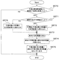
次に、本実施例における作業成績出力装置302が行う処理の一例を図11に示すフローチャートを用いて説明する。
次に、本実施例における作業成績出力装置302が行う処理の一例を図11に示すフローチャートを用いて説明する。
まず、作業成績出力装置302は、図5に示すような作業成績演算装置301から演算終了の信号を受信したか否かを判定する(ステップS520)。押下されたと判定されるときはステップS521に処理を進め、押下されていないと判定されるときは処理を終了する。
ステップS520において作業成績演算スイッチ800が押下されたと判定された場合、作業成績演算装置301で演算された作業成績および状態量演算装置300で演算された作業成績演算時に使用した各状態量を主記憶装置304から読み込む(ステップS521)。
次に、図5の状態量表示選択領域801により、表示する状態量を決定する(ステップS522)。
次に、作業成績表示設定領域802に入力された値に従った過去の作業成績と、その作業成績演算に使用し、ステップS522において決定された各状態量を主記憶装置304から読み込む(ステップS523)。
次に、ステップS521及びステップS523で読み込んだ作業成績と各状態量とを合せてモニタ装置303に出力する(ステップS524)。モニタ装置303では、図5の表示画面に従って、作業成績表示領域700に作業成績を表示し、作業成績演算時に使用した各状態量を状態量表示領域701に表示する。本実施例の状態量表示領域701の各状態量のグラフの横軸は作業回数であり、縦軸は正規化された各状態量である。
なお、作業成績演算装置301からの演算終了信号を受信することで作業成績出力装置302による処理が実行されるようにしたが、作業成績出力用の別のスイッチを設け、このスイッチからの信号を受信することにより処理を実行するようにしても良い。
<本実施例のまとめ>
上記のように構成され動作する本実施例の作業機械の操作支援装置では、油圧ショベル100が行った作業に対して、作業成績演算スイッチ800が押下された場合に、あらかじめ設定された時間(例えば5分)における作業量と燃料消費量の時間当たりの平均値とその間の各状態量を求めるとともに、これら各状態量から作業成績を演算する。その上で演算した作業成績と作業成績演算時に使用した各状態量を表示する。
上記のように構成され動作する本実施例の作業機械の操作支援装置では、油圧ショベル100が行った作業に対して、作業成績演算スイッチ800が押下された場合に、あらかじめ設定された時間(例えば5分)における作業量と燃料消費量の時間当たりの平均値とその間の各状態量を求めるとともに、これら各状態量から作業成績を演算する。その上で演算した作業成績と作業成績演算時に使用した各状態量を表示する。
これにより、油圧ショベル100のオペレータに対して自身の作業成績を通知することができ、効率的な作業が行われているか否かを総合的に評価することが可能となる。したがって、燃料消費量だけではなく、作業時間や作業量を含むオペレータの作業効率・スキルレベルの向上(改善)に寄与することができる。
また、前述の作業成績に加えて各状態量と過去の作業成績とその作業成績演算時に使用した各状態量を合わせて表示することで、オペレータは、自身の作業効率の改善、スキルレベルの向上も確認でき、更なる作業効率、スキルレベルの向上が期待できる。
なお、図5および図6はタッチパネルを想定した表示画面となっているが、通常のモニタ装置でも同様の表示を実現することができる。
また、本実施例において、モニタ装置303の表示画面は図5および図6に示した態様としたが、各領域の配置はこの限りではない。また表示する領域の種類もこれらに限定されない。
<第2の実施例>
本発明の作業機械の操作支援装置の第2の実施例を図12乃至図14を用いて説明する。
本発明の作業機械の操作支援装置の第2の実施例を図12乃至図14を用いて説明する。
本実施例の作業機械の操作支援装置は、以下に記述する内容以外については前述した第1の実施例の作業機械の操作支援装置と略同じ構成であり、詳細は省略する。
<操作支援装置の基本構成>
図12に本実施例における作業機械の操作支援装置202の構成を示す。図4との相違点は、影響度演算装置305が追加されたことにある。
図12に本実施例における作業機械の操作支援装置202の構成を示す。図4との相違点は、影響度演算装置305が追加されたことにある。
図12において、影響度演算装置305は、作業成績に対する各状態量の相対的な影響度合いを表す影響度を演算する装置であり、作業成績演算時に使用した各状態量と作業成績演算装置301で演算した作業成績から、後述する演算方法で影響度を演算する。
また、作業成績出力装置302は、影響度演算装置305によって演算された作業成績に対する作業量、作業時間、燃料消費量の影響度をモニタ装置303に対して出力する。
<影響度演算装置の処理動作>
次に、影響度演算装置305が行う演算処理を図13に示すフローチャートを用いて説明する。
次に、影響度演算装置305が行う演算処理を図13に示すフローチャートを用いて説明する。
まず、影響度演算装置305は、作業成績演算装置301から演算が終了した旨の信号を受信したかどうかを判定する(ステップS529)。受信していない場合には処理を終了し、受信している場合には次のステップS530へ移行する。次のステップS530では、作業成績演算装置301で演算した作業成績と各状態量を主記憶装置304から取得する(ステップS530)。
次に、作業成績と作業成績演算時に使用した各状態量から次式2~4に示す演算方法で作業成績に対する各状態量の影響度を演算する(ステップS531)。



次に、演算した影響度を相互に比較し「良、中、悪」で評価する(ステップS532)。たとえば、作業量=0.75、作業時間=0.8、燃料消費量=0.83となった場合、α,β,γ=1とすると式1より作業成績=3.2と演算され、求めた各値を式2~4にそれぞれ代入することで各状態量の作業成績に対する影響度は以下の式5~7のように演算される。



上記のように演算した影響度は、作業時間の影響度が一番大きく「良」、次に作業量の影響度が一番小さいため「悪」、燃料消費量は「中」として評価される。
次に、ステップS532で求めた影響度の評価結果を、作業成績出力装置302に出力する(ステップS533)。
<作業成績出力装置の処理動作>
本実施例における作業成績出力装置302は、第1の実施例での動作に加えて、前述の影響度の評価結果をモニタ装置303に出力する。
本実施例における作業成績出力装置302は、第1の実施例での動作に加えて、前述の影響度の評価結果をモニタ装置303に出力する。
<モニタ装置の画面構成>
本実施例におけるモニタ装置303の表示の一例を図14に示す。図5との相違点は、影響度表示部702と影響度表示選択部803が追加されたことにある。
本実施例におけるモニタ装置303の表示の一例を図14に示す。図5との相違点は、影響度表示部702と影響度表示選択部803が追加されたことにある。
影響度表示選択部803の選択によって、影響度表示部702に影響度の評価結果を表示するか否かを決定する。
<本実施例のまとめ>
本発明の作業機械の操作支援装置の第2の実施例においても、前述した作業機械の操作支援装置の第1の実施例とほぼ同様な効果が得られる。
本発明の作業機械の操作支援装置の第2の実施例においても、前述した作業機械の操作支援装置の第1の実施例とほぼ同様な効果が得られる。
加えて、作業成績に対する各状態量の影響度を知ることが可能となる。
例えば、本実施例においては、作業量の影響度が「悪」となるため、作業成績に対する
3つの指標のうち、作業量が燃料消費量や作業時間に比べ作業成績への寄与が小さかったということである。この場合は、例えば1回あたりの掘削土量をこれまでより増やすなど作業量を多くするよう工夫することが、作業時間を短くすることや燃料消費量をより良くすることよりも作業成績を改善するために有効であると見込まれることになる。つまり、オペレータはどの状態量を改善すれば作業成績が良くなり、結果として作業効率を向上させることができるか把握することが可能となり、オペレータのスキルレベルの向上を図ることができる。
3つの指標のうち、作業量が燃料消費量や作業時間に比べ作業成績への寄与が小さかったということである。この場合は、例えば1回あたりの掘削土量をこれまでより増やすなど作業量を多くするよう工夫することが、作業時間を短くすることや燃料消費量をより良くすることよりも作業成績を改善するために有効であると見込まれることになる。つまり、オペレータはどの状態量を改善すれば作業成績が良くなり、結果として作業効率を向上させることができるか把握することが可能となり、オペレータのスキルレベルの向上を図ることができる。
なお、本実施例における影響度は、作業量、作業時間、燃料消費量のどの指標が他の指標に比べて良好であるかを示す相対的な指標であり、これら3つの指標のバランスをよくするための指標となっている。そのため、作業量、作業時間、燃料消費量のすべてが平均的に悪いと、作業成績が悪く、各状態量の影響度にほとんど差がないように表示される。この場合には、作業量、作業時間、燃料消費量の全体的な改善が必要であることが分かることになる。また、作業量および作業時間が非常に良好であるのに対して燃料消費量が平均的であれば、作業成績は良好であり、影響度では燃料消費量が悪いと表示され、この場合燃料消費量の改善に注力すればよいことが一目で分かることになる。
なお、本実施例においては、各状態量の影響度の評価結果を表示する際に「良・中・悪」として表示したが、表示例はこの限りではない。例えば、「大、中、小」や、「1位、2位、3位」のように表示することや、演算した影響度を数値で表示することができ、作業成績に対する各状態量の影響度を相対的に判定することができれば表示形態は任意である。
<第3の実施例>
本発明の作業機械の操作支援装置の第3の実施例を図15乃至図17を用いて説明する。
本発明の作業機械の操作支援装置の第3の実施例を図15乃至図17を用いて説明する。
本実施例の作業機械の操作支援装置は、以下に記述する内容以外については前述した第1の実施例の作業機械の操作支援装置と略同じ構成であり、詳細は省略する。
<操作支援装置の基本構成>
図15に本実施例における作業機械の操作支援装置203の構成を示す。図4との相違点は、演算期間設定装置306が追加された点にある。
図15に本実施例における作業機械の操作支援装置203の構成を示す。図4との相違点は、演算期間設定装置306が追加された点にある。
図15において、演算期間設定装置306は、後述する方法で設定された期間内の作業に対して、状態量演算装置300が各状態量を演算する期間を設定するための装置である。
また、状態量演算装置300は、演算期間設定装置306で設定された基準期間の間の各状態量を求める。
<モニタ装置の画面構成>
次に、本実施例におけるモニタ装置303の表示画面の一例を図16に示す。図5との相違点は、表示画面内に演算期間選択部804が追加された点にある。
次に、本実施例におけるモニタ装置303の表示画面の一例を図16に示す。図5との相違点は、表示画面内に演算期間選択部804が追加された点にある。
本実施例における演算期間設定装置306は、演算期間を選択する演算期間選択部804によって選択された演算期間(1分、1時間、1日、1ヵ月)に従って、前述の作業成績演算装置301が作業成績演算時に使用する各状態量を求める期間を設定する。
本実施においては、1分、1時間、1日、1ヵ月を選択肢として示したが、設定期間の選択肢はこの限りではなく、期間は任意に設定可能である。
<作業成績演算装置の処理動作>
本実施例における作業成績演算装置301が行う演算処理の一例を図17に示すフローチャートを用いて説明する。図17の図10との相違点は、演算期間設定装置306で設定された演算期間を読み込むステップS541が追加された点である。
本実施例における作業成績演算装置301が行う演算処理の一例を図17に示すフローチャートを用いて説明する。図17の図10との相違点は、演算期間設定装置306で設定された演算期間を読み込むステップS541が追加された点である。
まず、作業成績演算装置301は、図5に示すような作業成績演算スイッチ800が押下されたか否かを判定する(ステップS540)。押下されたと判定されるときはステップS541に処理を進め、押下されていないと判定されるときは処理を終了する。
ステップS540において作業成績演算スイッチ800が押下されたと判定された場合、演算期間設定装置306にて設定された演算期間を読み込む(ステップS541)。
次に、ステップS541で読み込んだ演算期間内に行われた作業の各状態量を取得する(ステップS542)。
その後、ステップS542で取得した各状態量を用いて、第1の実施例の図10のステップS512~S515に示す手順と同様の手順で各状態量および作業成績を演算し、演算した作業成績と作業成績演算時に使用した各状態量を主記憶装置304に格納する(ステップS546)。その後、演算が終了した旨を伝える信号を作業成績出力装置302に出力する(ステップS547)。
<本実施例のまとめ>
本発明の作業機械の操作支援装置の第3の実施例においても、前述した作業機械の操作支援装置の第1の実施例とほぼ同様な効果が得られる。
本発明の作業機械の操作支援装置の第3の実施例においても、前述した作業機械の操作支援装置の第1の実施例とほぼ同様な効果が得られる。
加えて、作業成績の演算時に使用する各状態量の期間を任意に設定できることから、1日の作業の中で、作業量の異なる掘削積込み作業や整形作業を切り替えて行うような場合においても、作業成績の演算時に使用する各状態量の期間を設定することで、各作業における作業成績を演算することも可能となり、各作業毎の作業効率・スキルレベルの向上を図ることができ、更なるオペレータの作業効率・スキルレベルの向上を促すことができる。
<第4の実施例>
本発明の作業機械の操作支援装置の第4の実施例を図18乃至図20を用いて説明する。
本発明の作業機械の操作支援装置の第4の実施例を図18乃至図20を用いて説明する。
本実施例の作業機械の操作支援装置は、以下に記述する内容以外については前述した第1の実施例の作業機械の操作支援装置と略同じ構成であり、詳細は省略する。
<操作支援装置の基本構成>
図18に本実施例における作業機械の操作支援装置204の構成を示す。図4との相違点は、外部記憶装置900と通信するための外部通信装置310が追加された点である。
図18に本実施例における作業機械の操作支援装置204の構成を示す。図4との相違点は、外部記憶装置900と通信するための外部通信装置310が追加された点である。
外部通信装置310は、作業成績出力装置302の求めに応じ、作業成績演算装置301が作業成績演算時に用いた作業量、作業時間および燃料消費量の各状態量および演算した作業成績を油圧ショベル100の外部にある外部記憶装置900に送信する機能と、他機のオペレータの作業成績とその作業成績の演算時に使用した各状態量を外部記憶装置900から受信する機能を有しており、後述する方法を用いて外部記憶装置900との通信を行う。この外部通信装置310と外部記憶装置900との通信は、公知の方法を用いることができる。
外部記憶装置900は、外部通信装置310から送信された作業成績、作業量、作業時間、燃料消費量を作業機械ごとに記憶する。
<モニタ装置303の画面構成>
次に、本実施例におけるモニタ装置303の表示画面の一例を図19に示す。図5との相違点は、表示画面内に他機のオペレータとの比較選択スイッチ810が追加された点と、作業成績表示領域700と状態量表示領域701に他機のオペレータの作業成績、その作業成績演算時に使用した各状態量が自身の作業成績と作業成績演算時に使用した各状態量とが合わせて表示される点にある。
次に、本実施例におけるモニタ装置303の表示画面の一例を図19に示す。図5との相違点は、表示画面内に他機のオペレータとの比較選択スイッチ810が追加された点と、作業成績表示領域700と状態量表示領域701に他機のオペレータの作業成績、その作業成績演算時に使用した各状態量が自身の作業成績と作業成績演算時に使用した各状態量とが合わせて表示される点にある。
図19に示すような比較選択スイッチ810が押下されると、作業成績出力装置302は外部通信装置310を介して、外部記憶装置900に記憶された他機のオペレータの作業成績とその作業成績の演算時に使用した各状態量を受信する。作業成績出力装置302は、自身の作業成績とその作業成績演算時に使用した各状態量に加えて、この受信した他機のオペレータの作業成績とその作業成績演算時に使用した各状態量を、図19に示すようにそれぞれ作業成績表示領域700と状態量表示領域701に表示する。
<作業成績出力装置-外部通信装置-の処理動作>
本実施例における作業成績出力装置302が行う処理の一例を図20に示すフローチャートを用いて説明する。図11との相違点は、作業成績と各状態量を外部記憶装置900に送信するステップS552、他機のオペレータとの比較選択スイッチ810が押下されたか否かを判定するステップS555、他機のオペレータの作業成績と、その作業成績の演算時に使用した各状態量を受信するステップS556、自身の作業成績と他機のオペレータの作業成績をモニタ装置303に出力するステップS557が追加された点である。
本実施例における作業成績出力装置302が行う処理の一例を図20に示すフローチャートを用いて説明する。図11との相違点は、作業成績と各状態量を外部記憶装置900に送信するステップS552、他機のオペレータとの比較選択スイッチ810が押下されたか否かを判定するステップS555、他機のオペレータの作業成績と、その作業成績の演算時に使用した各状態量を受信するステップS556、自身の作業成績と他機のオペレータの作業成績をモニタ装置303に出力するステップS557が追加された点である。
図20において、まず作業成績出力装置302は、作業成績演算装置301から演算が終了した旨の信号を受信したか否かを判定する(ステップS550)。受信していると判定されるときはステップS551に処理を進め、受信していないと判定されるときは処理を終了する。
ステップS550において作業成績演算スイッチ800が押下されたと判定される場合は、作業成績出力装置302は、演算した作業成績と作業成績演算時に使用した各状態量を主記憶装置304から読み込む(ステップS551)。
次に、演算した作業成績と作業成績演算時に使用した各状態量を外部通信装置310を介して外部記憶装置900に対して出力する(ステップS552)。外部記憶装置900は、演算した作業成績と作業成績演算時に使用した各状態量を作業機械ごとに記憶しておく。
次に、図20に示す状態量表示選択領域801の各状態量のON/OFF状態から、表示する状態量を決定する(ステップS553)。
次に、過去の作業成績表示設定領域802に入力された値に従った過去の作業成績と、その作業成績演算に使用し、ステップS553に応じた過去の各状態量を主記憶装置304から読み込む(ステップS554)。
次に、他機のオペレータとの比較選択スイッチ810が押下されたか否かを判定する(ステップS555)。比較選択スイッチ810が押下されたと判定されるときはステップS556に処理を進め、比較選択スイッチ810が押下されていないと判定されるときは処理をステップS559に進める。
次に、あらかじめ設定した他機のオペレータの作業成績とその作業成績の演算時に使用した各状態量を外部通信装置310を介して外部記憶装置900から受信する(ステップS556)。
次いで、図11に示した第1の実施例の作業成績出力装置302のステップS524と同様に演算した作業成績と作業成績演算時に使用した各状態量を過去の作業成績と過去の作業成績演算時に使用した各状態量とを合わせてモニタ装置303へ出力するとともに、他機のオペレータの作業成績とその作業成績の演算時に使用した各状態量をモニタ装置303に出力する(ステップS557)。
これに対し、ステップS555の判定で他機のオペレータとの比較選択スイッチ810が押下されていないと判定された場合は、図11に示した第1の実施例の作業成績出力装置302のステップS524と同様に、作業成績とその作業成績演算時に使用した各状態量と、過去の作業成績と過去の作業成績演算時に使用した各状態量をモニタ装置303に出力する(ステップS559)。
<本実施例のまとめ>
本発明の作業機械の操作支援装置の第4の実施例においても、前述した作業機械の操作支援装置の第1の実施例とほぼ同様な効果が得られる。
本発明の作業機械の操作支援装置の第4の実施例においても、前述した作業機械の操作支援装置の第1の実施例とほぼ同様な効果が得られる。
加えて、他機のオペレータの作業成績と自身の作業成績を合わせて表示することが可能となる。これにより、オペレータは自身の作業成績と各状態量を他機のオペレータと比較、例えば自身の作業成績より高い作業成績のオペレータとの比較が可能となり、作業効率・スキルレベルの更なる向上が期待できる。
<第5の実施例>
本発明の作業機械の操作支援装置の第5の実施例を図21および図22を用いて説明する。
本発明の作業機械の操作支援装置の第5の実施例を図21および図22を用いて説明する。
本実施例の作業機械の操作支援装置は、以下に記述する内容以外については前述した第4の実施例の作業機械の操作支援装置と略同じ構成であり、詳細は省略する。
<操作支援装置の基本構成>
図21に本実施例における作業機械の操作支援装置205の構成を示す。図21と図18との相違点は、各オペレータの作業成績を比較するレポートを作成する作業成績比較装置901、各オペレータの作業成績を比較するレポートを表示するモニタ装置709が追加された点である。
図21に本実施例における作業機械の操作支援装置205の構成を示す。図21と図18との相違点は、各オペレータの作業成績を比較するレポートを作成する作業成績比較装置901、各オペレータの作業成績を比較するレポートを表示するモニタ装置709が追加された点である。
外部記憶装置900は、外部通信装置310から送信された作業成績、作業量、作業時間、燃料消費量を作業機械ごとに記憶する。
作業成績比較装置901は、外部記憶装置900に記憶された作業機械ごとの作業成績を比較し、何れの作業機械の作業成績が優れているかなど、各作業機械の作業成績の順位付けを行い、レポートを作成する。
モニタ装置709は、作業成績比較装置901で比較した各作業機械の比較結果のレポートを表示する。
<モニタ装置709の画面構成、レポートの表示方法>
図22に本実施例におけるモニタ装置709に表示されるレポートの一例を示す。
図22に本実施例におけるモニタ装置709に表示されるレポートの一例を示す。
図示しない各オペレータの比較スイッチが押下されると、図22に示すような画面がモニタ装置709に表示される。
図22において、表示領域710では、選択したオペレータのあらかじめ設定した作業回数前から直前の作業までの作業成績と、あらかじめ設定した他機のオペレータ(例えば、最高順位のオペレータ、基準となるオペレータ)の作業成績を数値で表示する。表示領域711では前述の作業成績を演算する際に使用した各状態量を表示する。表示領域712では、外部記憶装置900内に保存された作業成績と、選択したオペレータの作業成績を比較することで、演算する選択したオペレータの作業成績の順位を表示する。
<本実施例のまとめ>
本発明の作業機械の操作支援装置の第5の実施例においても、前述した作業機械の操作支援装置の第1の実施例とほぼ同様な効果が得られる。
本発明の作業機械の操作支援装置の第5の実施例においても、前述した作業機械の操作支援装置の第1の実施例とほぼ同様な効果が得られる。
加えて、本実施例の作業機械の操作支援装置によれば、第4の実施例の効果に加えて、作業機械の外部、例えば管理局や事務所等に駐在する管理者が、選択したオペレータの作業成績と、作業成績演算時に使用した各状態量と、当該オペレータの作業成績の順位を確認することができる。これにより各作業機械の作業成績を一元的に管理することができ、このレポートを各オペレータにフィードバックすることで作業機械の稼働する現場全体での作業成績の向上に貢献することができる。また、オペレータは、作業終了時に自分の作業成績をレポートとして受け取ることができ、作業機械上で作業成績を確認していない場合においても、オペレータに作業成績を知らせることが可能となり、より確実にオペレータの作業成績向上を促すことが可能となる。
なお、作業成績比較装置901は、外部記憶装置900に記憶された作業機械ごとの作業成績に加えて、作業成績の演算に使用した各状態量を作業機械ごとに比較し、各作業機械の各状態量の順位付けを行うことができる。
<第6の実施例>
本発明の作業機械の操作支援装置の第6の実施例を図23乃至図25を用いて説明する。
本発明の作業機械の操作支援装置の第6の実施例を図23乃至図25を用いて説明する。
本実施例の作業機械の操作支援装置は、以下に記述する内容以外については前述した第1の実施例の作業機械の操作支援装置と略同じ構成であり、詳細は省略する。
<モニタ装置の画面構成>
図23に図5の設定スイッチ704が押下された時の設定画面の表示例を示す。
図23に図5の設定スイッチ704が押下された時の設定画面の表示例を示す。
図23において、図6との相違点は演算方法選択部806および目標値設定領域811が追加された点にある。各状態量の明確な目標値が存在している作業の場合、オペレータは演算方法選択部806の演算方法を目標値ありと選択し、目標値設定領域811に各状態量の目標値を設定する。
本実施例の作業機械の操作支援装置では、作業成績演算装置301は、状態量演算装置300で演算された作業量、作業時間および燃料消費量の各状態量に基づいて作業の効率を表す作業成績を演算する際に、目標値設定領域811で設定された目標値で正規化して演算し、主記憶装置304や作業成績出力装置302に対して出力する。
<作業成績演算装置の処理動作>
本実施例における作業成績演算装置301の演算処理の一例をフローチャートとして図24に示す。図10との相違点は、演算方法選択部806にて選択された演算方法を判定するステップS563、演算方法選択部806に応じて目標値設定領域811に入力された目標値を作業成績出力装置302に出力するステップS564、各状態量の目標値で各状態量を正規化するステップS565が追加された点である。
本実施例における作業成績演算装置301の演算処理の一例をフローチャートとして図24に示す。図10との相違点は、演算方法選択部806にて選択された演算方法を判定するステップS563、演算方法選択部806に応じて目標値設定領域811に入力された目標値を作業成績出力装置302に出力するステップS564、各状態量の目標値で各状態量を正規化するステップS565が追加された点である。
まず、作業成績演算装置301は、図5に示すような作業成績演算スイッチ800が押下されたか否かを判定する(ステップS560)。押下されたと判定されるときはステップS561に処理を進め、押下されていないと判定されるときは処理を終了する。
ステップS560において作業成績演算スイッチ800が押下されたと判定された場合、あらかじめ設定された過去から現在までの時間(たとえば5分)における各状態量を主記憶装置304から取得する(ステップS561)。
次に、ステップS561で取得した各状態量のうち、作業量と燃料消費量の時間平均値を演算する(ステップS562)。
次に、図23に示す演算方法選択部806の選択が目標値なし(1)と目標値あり(2)のいずれが選択されているかを判定する(ステップS563)。
「目標値あり(2)」の作業成績演算方法が選択されたと判定されるときは、目標値を作業成績出力装置302に送信する(ステップS564)。
次に、ステップS562で演算した作業量と燃料消費量の時間平均値と、ステップS561で取得した作業時間を図23の目標値設定領域811に入力された各状態量の目標値で正規化する(ステップS565)。たとえば、作業量の時間平均値が1[t]、図23の目標値設定領域811の作業量の目標値が4[t]となる場合、作業量は次式8のように計算できる。

次に、ステップS565で正規化した各状態量を用いて、第1の実施例のステップS514と同様に上述の式1を用いて作業成績を演算する(ステップS566)。
次に、演算した作業成績と作業成績演算時に使用した各状態量を、主記憶装置304に格納する(ステップS567)。その後、作業成績出力装置302に演算が終了した旨を伝える信号を出力する(ステップS568)。
また、ステップS563で「目標値なし(1)」が選択されたと判定されるときは、ステップS562で演算した作業量と燃料消費量の時間平均値を正規化し(ステップS568)、その後、ステップS568で正規化した各状態量を用いて、第1の実施例のステップS514と同様に上述の式1を用いて作業成績を演算する(ステップS566)。
<作業成績出力装置の処理動作>
本実施例における作業成績出力装置302が行う処理の一例をフローチャートとして図25に示す。図11との相違点は、作業成績演算装置301から演算終了信号を受信した場合に、演算方法選択部806にて選択された演算方法を判定するステップS571、演算方法選択部806に応じて目標値設定領域811に入力された目標値と演算した作業成績と作業成績演算時に使用した各状態量を主記憶装置304から読み込むステップS572が追加された点である。
本実施例における作業成績出力装置302が行う処理の一例をフローチャートとして図25に示す。図11との相違点は、作業成績演算装置301から演算終了信号を受信した場合に、演算方法選択部806にて選択された演算方法を判定するステップS571、演算方法選択部806に応じて目標値設定領域811に入力された目標値と演算した作業成績と作業成績演算時に使用した各状態量を主記憶装置304から読み込むステップS572が追加された点である。
まず、作業成績出力装置302は、図5に示すように作業成績演算装置301から演算終了信号を受信したか否かを判定する(ステップS570)。受信したと判定されるときはステップS571に処理を進め、受信していないと判定されるときは処理を終了する。
ステップS570において作業成績演算スイッチ800が受信したと判定された場合、図23に示す演算方法選択部806の選択が目標値なし(1)と目標値あり(2)のいずれが選択されているかを判定する(ステップS571)。
「目標値あり(2)」の作業成績演算方法が選択されたと判定されるときは、目標値設定領域811に入力された目標値と演算した作業成績と作業成績演算時に使用した各状態量を、主記憶装置304に出力する(ステップS572)。
その後、図5の状態量表示選択領域801の状態量のON/OFF状態から、表示する状態量を決定(ステップS573)し、過去の作業成績表示設定領域802に入力された値に従った過去の作業成績と、その作業成績演算に使用した過去の各状態量を主記憶装置304から読み込む(ステップS574)。その後、演算した作業成績と作業成績演算時に使用した各状態量を過去の作業成績と過去の作業成績演算時に使用した各状態量とを合わせてモニタ装置303に出力する(ステップS575)。モニタ装置303では、図5の表示画面に従って、作業成績表示領域700に作業成績を表示し、作業成績演算時に使用した各状態量を状態量表示領域701に表示する。
また、ステップS571で「目標値なし(1)」が選択されたと判定されるときは、演算した作業成績と作業成績演算時に使用した各状態量を、主記憶装置304に出力(ステップS576)し、ステップS573に処理を進める。
<本実施例のまとめ>
本発明の作業機械の操作支援装置の第6の実施例においても、前述した作業機械の操作支援装置の第1の実施例とほぼ同様な効果が得られる。
本発明の作業機械の操作支援装置の第6の実施例においても、前述した作業機械の操作支援装置の第1の実施例とほぼ同様な効果が得られる。
加えて、各状態量の明確な目標値が存在する作業において、作業成績演算時に使用する各状態量を各状態量の目標値で正規化することができる。そして目標値で正規化した各状態量を用いて作業成績を演算することで、効率的な作業が行われているか否かをより正確に評価することが可能となる。また、作業成績と作業成績演算時に使用した各状態量を表示することで、オペレータは改善すべき状態量をより正確に把握できるため、作業効率・スキルレベルの更なる向上を促すことができる。
<その他>
なお、本発明は上記の実施例に限られず、種々の変形、応用が可能なものである。上述の実施例は本発明を分かりやすく説明するために詳細に説明したものであり、必ずしも説明した全ての構成を備えるものに限定されるものではない。
なお、本発明は上記の実施例に限られず、種々の変形、応用が可能なものである。上述の実施例は本発明を分かりやすく説明するために詳細に説明したものであり、必ずしも説明した全ての構成を備えるものに限定されるものではない。
例えば、上述の実施例の状態量演算装置300では、作業フロント101の姿勢(ブーム14、アーム15、作業具102の角度)を、ブーム角度センサ14A、アーム角度センサ15Aおよび作業具角度センサ102Aにて計測された計測信号から演算し、その姿勢とブームシリンダ16の圧力信号とを比較することで作業量を演算する構成としたが、作業量を演算できる構成であれば演算方法は任意である。例えば、作業フロント101の作業具102取付け部にロードセルを装着し、ロードセルで作業量を計測する構成とすることができる。また、各シリンダ16~18の図示しないストローク計測器のストローク信号から、作業フロント101の姿勢を演算し、作業フロント101の姿勢とステップS500で変換したブームシリンダ16の圧力信号と比較することで、作業具102にかかる作業量を演算する構成とすることができる。
また、上述の実施例の状態量演算装置300では、作業量計測スイッチが押下された場合に作業量を計測する構成としたが、作業量を計測できればその構成は任意である。例えば、あらかじめ設定した姿勢時に作業量を計測する構成とすることができる。
更に、上述の実施例の状態量演算装置300では、レバー操作量信号40~47から作業時間を演算する構成としたが、作業時間を演算できる構成であればその構成は任意である。例えば、作業機械の作業フロント101を計測できる位置にカメラを設置し、カメラを用いてフロントが動いているか否かを検出し、作業フロント101が動作している時間を作業時間として計測する構成とすることができる。
また、上述の実施例では、状態量表示領域701に表示する状態量の表示方法を図5、図14、図16または図19のような画面としたが、状態量を表示する構成はこれに限定されない。例えば、数値の表示、散布図、レーダチャート、円グラフなど、状態量を表示する構成であればその表示形態は任意に選択することができる。同様に、作業成績表示領域700には、作業成績を数値で表示したが、数値以外の散布図、レーダチャート、円グラフなどその表示形態は任意である。
更に、上述の実施例では、作業機械としての油圧ショベルに取り付けられた作業フロント101の作業具102として、いわゆるバケットが取り付けられている場合について説明したが、作業具102は作業機械の作業内容に応じて任意に交換可能である。例えば、図26に示すようなグラップル103、図27に示すようなリフティングマグネット104や、カッタ、ブレーカ、その他の作業具のいずれか1つに任意に交換可能であり、交換後の油圧ショベルに対しても本発明の作業機械の操作支援装置を適用することができる。
また、上述の実施例では、作業フロント101として、図1に示すようなアーム15に上下回動自在に取り付けられた作業フロント101が設けられた構成としたが、作業フロント101はこの限りではない。作業フロント101は最低限1つのアクチュエータを有する構成であればよく、フロント数やフロント関節数、作業具の種類など、その構成は任意である。
更に、上述の実施例では操作装置の構成を図3に示した態様としたが、操作装置の態様はこの限りではない。操作装置は、各アクチュエータの駆動を指示可能な操作デバイスであれば良く、その幾何配置も任意である。また、操作レバーの操作軸と作業フロントの動作アクチュエータの関係についても任意の構成が取りうる。
また、上述の実施例では、油圧ショベルの動力源としてメインポンプを駆動するエンジンを用いる場合について説明したが、動力源はエンジンに限られず、内蔵バッテリまたは外部電源を電力源とする電動モータを用いてメインポンプを駆動することができる。この場合、動力消費量は「燃料消費量」ではなく「電力消費量」とし、電力消費量計測器によって電力消費量を計測する。また、ハイブリッド式油圧ショベルの場合、動力消費量は燃料消費量および電力消費量とする。
更に、上述の実施例では、作業機械として油圧ショベルを例に示して説明したが、作業機械は油圧ショベルに限定されず、ホイールローダやダンプトラック、ブルドーザーなどの作業機械に対しても本発明の作業機械の操作支援装置を適用することができる。
11…走行体、
12…旋回体、
13…運転室、
14…ブーム、
14A…ブーム角度センサ、
14B,15B,102B…角度検出信号、
15…アーム、
15A…アーム角度センサ、
16…ブームシリンダ、
16a,17a,18a…ボトム側油室、
16b,17b,18b…ロッド側油室、
17…アームシリンダ、
18…作業具シリンダ、
20…燃料タンク、
21…エンジン、
22…メインポンプ、
23…作動油タンク、
24…コントロール弁、
30…ブーム操作レバー、
31…アーム操作レバー、
32…作業具操作レバー、
33a…ブームレバー操作量計測器、
33b…アームレバー操作量計測器、
33c…作業具レバー操作量計測器、
34a,34b,35a,35b,36a,36b…圧力計測器、
37…燃料消費量計測器、
38…右操作レバー、
39…左操作レバー、
40~47…レバー操作量信号、
70~75…圧力信号、
90…燃料消費量信号、
100…油圧ショベル、
101…作業フロント、
102…作業具、
102A…作業具角度センサ、
103…グラップル、
104…リフティングマグネット、
200…コントローラ、
201,202,203,204,205…操作支援装置、
300…状態量演算装置、
301…作業成績演算装置、
302…作業成績出力装置、
303…モニタ装置、
304…主記憶装置、
305…影響度演算装置、
306…演算期間設定装置、
310…外部通信装置、
700…作業成績表示領域、
701…状態量表示領域、
702…影響度表示部、
704…設定スイッチ、
709…モニタ装置、
800…作業成績演算スイッチ、
801…状態量表示選択領域、
802…過去の作業成績表示設定領域、
803…影響度表示選択部、
804…演算期間選択部、
806…演算方法選択部、
807…重み設定領域、
810…比較選択スイッチ、
811…目標値設定領域、
820…復帰スイッチ、
900…外部記憶装置、
901…作業成績比較装置。
12…旋回体、
13…運転室、
14…ブーム、
14A…ブーム角度センサ、
14B,15B,102B…角度検出信号、
15…アーム、
15A…アーム角度センサ、
16…ブームシリンダ、
16a,17a,18a…ボトム側油室、
16b,17b,18b…ロッド側油室、
17…アームシリンダ、
18…作業具シリンダ、
20…燃料タンク、
21…エンジン、
22…メインポンプ、
23…作動油タンク、
24…コントロール弁、
30…ブーム操作レバー、
31…アーム操作レバー、
32…作業具操作レバー、
33a…ブームレバー操作量計測器、
33b…アームレバー操作量計測器、
33c…作業具レバー操作量計測器、
34a,34b,35a,35b,36a,36b…圧力計測器、
37…燃料消費量計測器、
38…右操作レバー、
39…左操作レバー、
40~47…レバー操作量信号、
70~75…圧力信号、
90…燃料消費量信号、
100…油圧ショベル、
101…作業フロント、
102…作業具、
102A…作業具角度センサ、
103…グラップル、
104…リフティングマグネット、
200…コントローラ、
201,202,203,204,205…操作支援装置、
300…状態量演算装置、
301…作業成績演算装置、
302…作業成績出力装置、
303…モニタ装置、
304…主記憶装置、
305…影響度演算装置、
306…演算期間設定装置、
310…外部通信装置、
700…作業成績表示領域、
701…状態量表示領域、
702…影響度表示部、
704…設定スイッチ、
709…モニタ装置、
800…作業成績演算スイッチ、
801…状態量表示選択領域、
802…過去の作業成績表示設定領域、
803…影響度表示選択部、
804…演算期間選択部、
806…演算方法選択部、
807…重み設定領域、
810…比較選択スイッチ、
811…目標値設定領域、
820…復帰スイッチ、
900…外部記憶装置、
901…作業成績比較装置。
Claims (6)
- 作業機械の操作支援装置であって、
前記作業機械の作業量を演算するために必要な状態値を計測する第1計測装置と、
前記作業機械の作業時間を演算するために必要な状態値を計測する第2計測装置と、
前記作業機械の動力消費量を演算するために必要な状態値を計測する第3計測装置と、
前記第1計測装置、前記第2計測装置および前記第3計測装置によって計測された各状態値に基づいて前記作業量、前記作業時間および前記動力消費量を演算する状態量演算装置と、
この状態量演算装置で演算された前記作業量、前記作業時間および前記動力消費量に基づいて作業の効率を表す作業成績を演算する作業成績演算装置と、
この作業成績演算装置で演算された前記作業成績を出力する作業成績出力装置とを備えた
ことを特徴とする作業機械の操作支援装置。 - 請求項1に記載の作業機械の操作支援装置において、
前記作業機械の運転室内部に設けられ、前記作業成績出力装置の出力した前記作業成績を表示する表示装置を更に備え、
前記作業成績出力装置は、前記作業成績に加えて、前記作業量、前記作業時間、前記動力消費量を前記表示装置に対して出力し、
前記表示装置は、前記作業成績に加えて、前記作業量、前記作業時間、前記動力消費量を表示する
ことを特徴とする作業機械の操作支援装置。 - 請求項1または2に記載の作業機械の操作支援装置において、
前記作業成績に対する前記作業量、前記作業時間、前記動力消費量の影響度を相対的に演算する影響度演算装置を更に備え、
前記作業成績出力装置は、前記影響度演算装置によって演算された前記作業成績に対する前記作業量、前記作業時間、前記動力消費量の影響度を出力する
ことを特徴とする作業機械の操作支援装置。 - 請求項1または2に記載の作業機械の操作支援装置において、
前記作業成績を演算する基準期間を設定する演算期間設定装置を更に備え、
前記状態量演算装置は、前記演算期間設定装置で設定された前記基準期間の間の前記作業量、前記作業時間および前記動力消費量を求める
ことを特徴とする作業機械の操作支援装置。 - 請求項1または2に記載の作業機械の操作支援装置において、
前記作業機械の外部に対して前記作業成績、前記作業量、前記作業時間、前記動力消費量を送信する外部通信装置を更に備えた
ことを特徴とする作業機械の操作支援装置。 - 請求項5に記載の作業機械の操作支援装置において、
前記外部通信装置から送信された前記作業成績、前記作業量、前記作業時間、前記動力消費量を作業機械ごとに記憶する外部記憶装置と、
この外部記憶装置に記憶された作業成績を他の作業機械の作業成績と比較する作業成績比較装置と、
この作業成績比較装置で比較した結果を表示する外部表示装置とを更に備えた
ことを特徴とする作業機械の操作支援装置。
Applications Claiming Priority (2)
| Application Number | Priority Date | Filing Date | Title |
|---|---|---|---|
| JP2015-016031 | 2015-01-29 | ||
| JP2015016031A JP6430272B2 (ja) | 2015-01-29 | 2015-01-29 | 作業機械の操作支援装置 |
Publications (1)
| Publication Number | Publication Date |
|---|---|
| WO2016121243A1 true WO2016121243A1 (ja) | 2016-08-04 |
Family
ID=56542877
Family Applications (1)
| Application Number | Title | Priority Date | Filing Date |
|---|---|---|---|
| PCT/JP2015/084728 Ceased WO2016121243A1 (ja) | 2015-01-29 | 2015-12-10 | 作業機械の操作支援装置 |
Country Status (2)
| Country | Link |
|---|---|
| JP (1) | JP6430272B2 (ja) |
| WO (1) | WO2016121243A1 (ja) |
Cited By (3)
| Publication number | Priority date | Publication date | Assignee | Title |
|---|---|---|---|---|
| CN112654753A (zh) * | 2018-07-31 | 2021-04-13 | 株式会社小松制作所 | 指标值确定装置及指标值确定方法 |
| EP3666584A4 (en) * | 2018-09-28 | 2021-04-21 | Hitachi Construction Machinery Tierra Co., Ltd. | ELECTRICALLY POWERED CONSTRUCTION MACHINE |
| CN118911229A (zh) * | 2024-07-16 | 2024-11-08 | 山东临工工程机械有限公司 | 挖掘机档位选择控制用数据采集装置及其选择控制方法 |
Families Citing this family (11)
| Publication number | Priority date | Publication date | Assignee | Title |
|---|---|---|---|---|
| JP6425618B2 (ja) * | 2015-06-01 | 2018-11-21 | 日立建機株式会社 | 作業機械の操作支援装置 |
| JP6617088B2 (ja) * | 2016-09-13 | 2019-12-04 | 日立建機株式会社 | 油圧ショベルの作業効率指標表示システム |
| JP7152148B2 (ja) * | 2017-12-18 | 2022-10-12 | 住友重機械工業株式会社 | 建設機械 |
| JP2019120193A (ja) * | 2018-01-05 | 2019-07-22 | 日立建機株式会社 | 作業機械の燃料消費量測定システム |
| JP7293822B2 (ja) | 2019-04-05 | 2023-06-20 | コベルコ建機株式会社 | 技能評価システム及び技能評価方法 |
| JP2020170474A (ja) * | 2019-04-05 | 2020-10-15 | コベルコ建機株式会社 | スキル情報提示システム及びスキル情報提示方法 |
| JP7302244B2 (ja) | 2019-04-05 | 2023-07-04 | コベルコ建機株式会社 | スキル情報提示システム及びスキル情報提示方法 |
| JP7455632B2 (ja) * | 2020-03-30 | 2024-03-26 | 住友重機械工業株式会社 | ショベル及びショベルの管理装置 |
| JP7845606B2 (ja) * | 2021-10-19 | 2026-04-14 | 住友建機株式会社 | ショベル、ショベルの管理システム、ショベルの管理装置 |
| US20250003201A1 (en) | 2021-12-03 | 2025-01-02 | Kobelco Construction Machinery Co., Ltd. | Image display system, image display composite system, and image display method |
| JP2025006200A (ja) * | 2023-06-29 | 2025-01-17 | 株式会社小松製作所 | 作業機械の表示制御システム |
Citations (4)
| Publication number | Priority date | Publication date | Assignee | Title |
|---|---|---|---|---|
| JP4173121B2 (ja) * | 2003-09-02 | 2008-10-29 | 株式会社小松製作所 | 建設機械の運転システム |
| WO2009119715A1 (ja) * | 2008-03-26 | 2009-10-01 | 株式会社小松製作所 | 建設機械の送受信システムにおける運転操作ガイダンス装置 |
| JP2009235833A (ja) * | 2008-03-28 | 2009-10-15 | Komatsu Ltd | 建設機械の運転評価システム及び運転評価方法 |
| JP2012144308A (ja) * | 2011-01-07 | 2012-08-02 | Sumitomo Heavy Ind Ltd | 荷役作業車両の管理装置及び管理方法 |
-
2015
- 2015-01-29 JP JP2015016031A patent/JP6430272B2/ja active Active
- 2015-12-10 WO PCT/JP2015/084728 patent/WO2016121243A1/ja not_active Ceased
Patent Citations (4)
| Publication number | Priority date | Publication date | Assignee | Title |
|---|---|---|---|---|
| JP4173121B2 (ja) * | 2003-09-02 | 2008-10-29 | 株式会社小松製作所 | 建設機械の運転システム |
| WO2009119715A1 (ja) * | 2008-03-26 | 2009-10-01 | 株式会社小松製作所 | 建設機械の送受信システムにおける運転操作ガイダンス装置 |
| JP2009235833A (ja) * | 2008-03-28 | 2009-10-15 | Komatsu Ltd | 建設機械の運転評価システム及び運転評価方法 |
| JP2012144308A (ja) * | 2011-01-07 | 2012-08-02 | Sumitomo Heavy Ind Ltd | 荷役作業車両の管理装置及び管理方法 |
Cited By (6)
| Publication number | Priority date | Publication date | Assignee | Title |
|---|---|---|---|---|
| CN112654753A (zh) * | 2018-07-31 | 2021-04-13 | 株式会社小松制作所 | 指标值确定装置及指标值确定方法 |
| CN112654753B (zh) * | 2018-07-31 | 2022-07-29 | 株式会社小松制作所 | 指标值确定装置及指标值确定方法 |
| US11905685B2 (en) | 2018-07-31 | 2024-02-20 | Komatsu Ltd. | Index-value determination device and index-value determination method |
| EP3666584A4 (en) * | 2018-09-28 | 2021-04-21 | Hitachi Construction Machinery Tierra Co., Ltd. | ELECTRICALLY POWERED CONSTRUCTION MACHINE |
| US11136743B2 (en) | 2018-09-28 | 2021-10-05 | Hitachi Construction Machinery Tierra Co., Ltd | Electric construction machine |
| CN118911229A (zh) * | 2024-07-16 | 2024-11-08 | 山东临工工程机械有限公司 | 挖掘机档位选择控制用数据采集装置及其选择控制方法 |
Also Published As
| Publication number | Publication date |
|---|---|
| JP6430272B2 (ja) | 2018-11-28 |
| JP2016141940A (ja) | 2016-08-08 |
Similar Documents
| Publication | Publication Date | Title |
|---|---|---|
| JP6430272B2 (ja) | 作業機械の操作支援装置 | |
| JP6333598B2 (ja) | ショベル支援装置及びショベル | |
| AU2018200481B2 (en) | Stress or accumulated damage monitoring system | |
| US8185290B2 (en) | Data acquisition system indexed by cycle segmentation | |
| AU2009221767B2 (en) | Adaptive payload monitoring system | |
| CN105275043B (zh) | 挖土机支援装置 | |
| US8135518B2 (en) | Linkage control system with position estimator backup | |
| JP4705099B2 (ja) | 作業機械 | |
| JP7022018B2 (ja) | 作業機械 | |
| CN113761673A (zh) | 用于确定由工作机械执行的工作过程的过程数据的方法和系统 | |
| JPWO2017159748A1 (ja) | ショベル | |
| JP6675809B2 (ja) | ショベル支援装置 | |
| KR101625682B1 (ko) | 건설기계의 연비표시장치와 연비표시방법 및 표준연비 산출방법 | |
| CN204140543U (zh) | 液压缸中的位置传感器组件 | |
| JP7069945B2 (ja) | 建設機械の作動油量測定装置 | |
| JP5009827B2 (ja) | 作業機械 | |
| CN108331065A (zh) | 挖土机 | |
| JP2020122371A (ja) | 作業機械 | |
| JP2016223201A (ja) | 作業機械の操作支援装置 | |
| JP2023061194A (ja) | ショベル、ショベルの管理システム、ショベルの管理装置 | |
| CN121205257A (zh) | 一种挖掘机的控制方法、装置、控制设备及挖掘机 | |
| CN121079468A (zh) | 监测挖掘操作的方法 |
Legal Events
| Date | Code | Title | Description |
|---|---|---|---|
| 121 | Ep: the epo has been informed by wipo that ep was designated in this application |
Ref document number: 15880135 Country of ref document: EP Kind code of ref document: A1 |
|
| NENP | Non-entry into the national phase |
Ref country code: DE |
|
| 32PN | Ep: public notification in the ep bulletin as address of the adressee cannot be established |
Free format text: NOTING OF LOSS OF RIGHTS PURSUANT TO RULE 112(1) EPC (EPO FORM 1205A DATED 28/11/2017) |
|
| 122 | Ep: pct application non-entry in european phase |
Ref document number: 15880135 Country of ref document: EP Kind code of ref document: A1 |