WO2016121069A1 - 作業車両 - Google Patents
作業車両 Download PDFInfo
- Publication number
- WO2016121069A1 WO2016121069A1 PCT/JP2015/052581 JP2015052581W WO2016121069A1 WO 2016121069 A1 WO2016121069 A1 WO 2016121069A1 JP 2015052581 W JP2015052581 W JP 2015052581W WO 2016121069 A1 WO2016121069 A1 WO 2016121069A1
- Authority
- WO
- WIPO (PCT)
- Prior art keywords
- boom
- vertical plate
- rotary encoder
- cylinder
- angle detector
- Prior art date
- Legal status (The legal status is an assumption and is not a legal conclusion. Google has not performed a legal analysis and makes no representation as to the accuracy of the status listed.)
- Ceased
Links
Images





Classifications
-
- E—FIXED CONSTRUCTIONS
- E02—HYDRAULIC ENGINEERING; FOUNDATIONS; SOIL SHIFTING
- E02F—DREDGING; SOIL-SHIFTING
- E02F9/00—Component parts of dredgers or soil-shifting machines, not restricted to one of the kinds covered by groups E02F3/00 - E02F7/00
- E02F9/26—Indicating devices
-
- E—FIXED CONSTRUCTIONS
- E02—HYDRAULIC ENGINEERING; FOUNDATIONS; SOIL SHIFTING
- E02F—DREDGING; SOIL-SHIFTING
- E02F3/00—Dredgers; Soil-shifting machines
- E02F3/04—Dredgers; Soil-shifting machines mechanically-driven
- E02F3/28—Dredgers; Soil-shifting machines mechanically-driven with digging tools mounted on a dipper- or bucket-arm, i.e. there is either one arm or a pair of arms, e.g. dippers, buckets
- E02F3/30—Dredgers; Soil-shifting machines mechanically-driven with digging tools mounted on a dipper- or bucket-arm, i.e. there is either one arm or a pair of arms, e.g. dippers, buckets with a dipper-arm pivoted on a cantilever beam, i.e. boom
- E02F3/32—Dredgers; Soil-shifting machines mechanically-driven with digging tools mounted on a dipper- or bucket-arm, i.e. there is either one arm or a pair of arms, e.g. dippers, buckets with a dipper-arm pivoted on a cantilever beam, i.e. boom working downwardly and towards the machine, e.g. with backhoes
-
- E—FIXED CONSTRUCTIONS
- E02—HYDRAULIC ENGINEERING; FOUNDATIONS; SOIL SHIFTING
- E02F—DREDGING; SOIL-SHIFTING
- E02F9/00—Component parts of dredgers or soil-shifting machines, not restricted to one of the kinds covered by groups E02F3/00 - E02F7/00
- E02F9/08—Superstructures; Supports for superstructures
- E02F9/0808—Improving mounting or assembling, e.g. frame elements, disposition of all the components on the superstructures
-
- E—FIXED CONSTRUCTIONS
- E02—HYDRAULIC ENGINEERING; FOUNDATIONS; SOIL SHIFTING
- E02F—DREDGING; SOIL-SHIFTING
- E02F9/00—Component parts of dredgers or soil-shifting machines, not restricted to one of the kinds covered by groups E02F3/00 - E02F7/00
- E02F9/08—Superstructures; Supports for superstructures
- E02F9/0833—Improving access, e.g. for maintenance, steps for improving driver's access, handrails
-
- E—FIXED CONSTRUCTIONS
- E02—HYDRAULIC ENGINEERING; FOUNDATIONS; SOIL SHIFTING
- E02F—DREDGING; SOIL-SHIFTING
- E02F9/00—Component parts of dredgers or soil-shifting machines, not restricted to one of the kinds covered by groups E02F3/00 - E02F7/00
- E02F9/08—Superstructures; Supports for superstructures
- E02F9/0858—Arrangement of component parts installed on superstructures not otherwise provided for, e.g. electric components, fenders, air-conditioning units
- E02F9/0883—Tanks, e.g. oil tank, urea tank, fuel tank
-
- E—FIXED CONSTRUCTIONS
- E02—HYDRAULIC ENGINEERING; FOUNDATIONS; SOIL SHIFTING
- E02F—DREDGING; SOIL-SHIFTING
- E02F9/00—Component parts of dredgers or soil-shifting machines, not restricted to one of the kinds covered by groups E02F3/00 - E02F7/00
- E02F9/14—Booms only for booms with cable suspension arrangements; Cable suspensions
-
- E—FIXED CONSTRUCTIONS
- E02—HYDRAULIC ENGINEERING; FOUNDATIONS; SOIL SHIFTING
- E02F—DREDGING; SOIL-SHIFTING
- E02F9/00—Component parts of dredgers or soil-shifting machines, not restricted to one of the kinds covered by groups E02F3/00 - E02F7/00
- E02F9/26—Indicating devices
- E02F9/264—Sensors and their calibration for indicating the position of the work tool
- E02F9/265—Sensors and their calibration for indicating the position of the work tool with follow-up actions (e.g. control signals sent to actuate the work tool)
Definitions
- the present invention relates to a work vehicle.
- a working vehicle such as a hydraulic excavator is provided with a lower traveling body having a crawler belt and an upper revolving body having a revolving frame and a working machine.
- the work machine includes a boom, an arm, a bucket, and the like.
- the boom is provided to be rotatable with respect to the revolving frame
- the arm is provided to be rotatable with respect to the boom
- the bucket is provided to be rotatable with respect to the arm.
- the boom, arm, and bucket are rotated by a hydraulic cylinder.
- the stroke length of the hydraulic cylinder is measured in order to detect the position / posture of the work implement.
- the cylinder which can detect stroke length is used for the hydraulic cylinder which rotates a boom.
- This cylinder is configured to detect the stroke position of a hydraulic cylinder by the rotation of a rotating roller on a cylinder rod. Since a minute slip occurs between the rotating roller and the cylinder rod, an error occurs between the stroke length obtained from the detection result of the position sensor and the actual stroke length.
- a rotary encoder is provided on the rotating shaft of the boom as an example of an angle detector. The time when the angle of the boom becomes a predetermined reference angle is detected by the rotary encoder, and the error generated in the cylinder is corrected.
- An object of the present invention is to provide a work vehicle that can effectively utilize a space outside a vertical plate.
- a work vehicle includes a frame, a boom, an angle detector, and a link member.
- the frame has a pair of first vertical plates and second vertical plates facing each other.
- the boom is rotatably supported by the first vertical plate and the second vertical plate.
- the angle detector is provided at a position different from the rotation axis of the boom.
- the link member transmits the rotation angle of the boom to the angle detector according to the rotation of the boom.
- the angle detector can be installed at a position different from the rotation axis of the boom.
- the position of an angle detector can be moved from the rotating shaft of a boom.
- the space of the rotating shaft side outside of the first vertical plate.
- the reducing agent tank can be installed in the space outside the first vertical plate.
- a work vehicle according to a second invention is the work vehicle according to the first invention, and the angle detector is disposed above the rotation axis.
- the components can be arranged close to the side of the first vertical plate, so that the space outside the first vertical plate can be used effectively.
- a work vehicle according to a third invention is the work vehicle according to the first invention, and further includes a tank.
- the tank is disposed on the frame and on the side of the first vertical plate.
- the angle detector is disposed above the tank.
- a work vehicle according to a fourth aspect is the work vehicle according to the third aspect, wherein the tank is a reducing agent tank.
- the reducing agent tank can be arranged close to the side of the first vertical plate.
- a work vehicle is the work vehicle according to the first aspect of the present invention, further comprising a support member.
- the support member is a plate-like member that is fixed to the first vertical plate and supports the angle detector.
- the angle detector is disposed on the second vertical plate side of the support member.
- components such as a reducing agent tank can be arranged close to the outside of the first vertical plate, and the first vertical plate The space outside the board can be used effectively.
- a work vehicle according to a sixth aspect is the work vehicle according to the first aspect, wherein the angle detector is disposed on the second vertical plate side of the first vertical plate.
- the angle detector is arranged on the second vertical plate side of the first vertical plate, components such as a reducing agent tank can be arranged close to the outside of the first vertical plate, The space outside the vertical plate can be used effectively.
- a work vehicle according to a seventh invention is the work vehicle according to the first invention, wherein the link member includes a first member connected to the angle detector and a second member connected to the boom. .
- the 1st member and the 2nd member are connected so that rotation is mutually possible.
- the first member is disposed in parallel to a straight line connecting the connecting portion between the second member and the boom and the rotating shaft of the boom, and the second member includes a connecting portion between the angle detector and the first member, It is arranged in parallel to a straight line connecting the rotation axis.
- a parallel link is constructed, the rotation angle of the boom and the angle detected by the angle detector have a one-to-one correspondence, and the rotation angle of the boom and the detection angle by the angle detector have the same value.
- the parallelism allows a mechanical error and includes a mechanical error and has a spread.
- the work vehicle which can utilize effectively the space of the outer side of a vertical board can be provided.
- FIG. 1 is an external perspective view of a hydraulic excavator according to an embodiment of the present invention.
- the front view which looked at the hydraulic excavator of FIG. 1 from the front side.
- the side view of the hydraulic excavator of FIG. FIG. 2 is a partially enlarged perspective view of the hydraulic excavator in FIG. 1.
- FIG. 2 is a partially enlarged perspective view of the hydraulic excavator in FIG. 1.
- the perspective view which shows the state which closed the cover of the reducing agent tank of FIG.
- the figure which shows the structure of the boom cylinder of the hydraulic shovel of FIG.
- FIG. 7A The side view which shows the state which removed the cover which covers a rotary encoder from FIG. 7A.
- the cross-sectional block diagram which shows the 2nd member of the link part of FIG.
- the side view which shows the structure of the link member vicinity of FIG.
- the side view which shows the structure of the link member vicinity of FIG.
- the side view which shows the structure of the link member vicinity of FIG.
- FIG. 1 is a diagram showing a hydraulic excavator 100 according to an embodiment of the present invention.
- the excavator 100 includes a vehicle body 1 and a work machine 4.
- the vehicle body 1 includes a traveling body 2 and a turning body 3.
- the traveling body 2 includes a pair of traveling devices 2a and 2b.
- Each traveling device 2a, 2b has crawler belts 2d, 2e.
- the crawler belts 2d and 2e are driven by the driving force from the engine, and the excavator 100 travels.
- the swivel body 3 has a swivel frame 10 placed on the traveling body 2, and is provided so as to be able to swivel with respect to the traveling body 2.
- a cab 5 as a cab is provided at the front left side position of the revolving structure 3 and above the revolving frame 10.
- a handrail 31 is installed on the top plate of the cab 5, and a GNSS (Global Navigation Satellite System) antenna 30 is provided on the handrail 31.
- the GNSS antenna 30 can obtain current position information of the work vehicle.
- the front-rear direction means the front-rear direction of the cab 5.
- the front-rear direction of the vehicle body 1 is the same as the front-rear direction of the cab 5, that is, the revolving structure 3.
- the left-right direction or the side means the vehicle width direction of the vehicle body 1.
- the swivel body 3 includes a reducing agent tank 15, a fuel tank, an engine, and the like disposed on the swivel frame 10, and a counterweight 6 is provided at the rear thereof.
- the work machine 4 includes a boom 7, an arm 8, and an excavation bucket 9, and is attached to the front center position of the swing body 3.
- the work machine 4 is disposed on the right side of the right side surface 5 a of the cab 5.
- a base end portion of the boom 7 is rotatably connected to the revolving structure 3.
- the distal end portion of the boom 7 is rotatably connected to the proximal end portion of the arm 8.
- a distal end portion of the arm 8 is rotatably connected to the excavation bucket 9.
- Boom cylinders 21 and 21 ′ are provided between the turning frame 10 and the boom 7.
- a cylinder connecting portion 7 a to which the boom cylinder 21 is connected is provided at the approximate center of the boom 7.
- the boom 7 includes a first boom portion 7b on the rear side from the cylinder connecting portion 7a and a second boom portion 7c on the front side from the cylinder connecting portion 7a.
- the boom 7 is bent so as to protrude upward in the vicinity of the cylinder connecting portion 7a.
- the arm cylinder 22 is provided between the boom 7 and the arm 8.
- a bucket cylinder 23 is provided between the arm 8 and the excavation bucket 9.
- the boom cylinder 21, the arm cylinder 22, and the bucket cylinder 23 are all hydraulic cylinders. By driving these hydraulic cylinders, the boom 7, the arm 8 and the excavation bucket 9 are rotated, and the work machine 4 is driven. Thereby, operations such as excavation are performed.
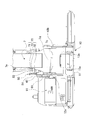
- FIG. 2A is a partial front view of the excavator 100 shown in FIG. 1 as viewed from the front side.
- the boom cylinders 21, 21 ′, the cab 5 and the like are omitted.
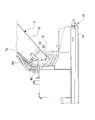
- FIG. 2B is a side view of FIG. 2A.
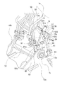
- FIG. 3 is a partially enlarged view showing the vicinity of the base end portion of the boom 7.
- a reducing agent tank 15 described later is omitted for explanation.
- the revolving frame 10 has a bottom plate 11 and a pair of first vertical plate 12a and second vertical plate 12b.
- the bottom plate 11 is disposed on the upper side of the traveling body 2.
- the first vertical plate 12 a and the second vertical plate 12 b are erected from the bottom plate 11 at the center of the front end of the bottom plate 11.
- the first vertical plate 12a and the second vertical plate 12b are disposed in parallel with the front-rear direction and face each other.
- the first vertical plate 12a is disposed on the right side, and the second vertical plate 12b is disposed on the left side.
- the base end portion 7d of the boom 7 is disposed between the first vertical plate 12a and the second vertical plate 12b, and rotates to the first vertical plate 12a and the second vertical plate 12b. Supported as possible.
- the rotating shaft of the boom 7 is shown as a shaft 7s.
- a reducing agent tank 15 is provided on the right side of the first vertical plate 12a in the vicinity of the first vertical plate 12a. A part of the reducing agent tank 15 is located at the same height as the shaft 7s. In a side view, the reducing agent tank 15 is disposed so as to overlap the shaft 7s.
- the reducing agent tank 15 stores a reducing agent precursor used to reduce nitrogen oxides in the exhaust from the engine. In the present specification, the precursor of the reducing agent is simply referred to as “reducing agent”. Examples of the reducing agent include urea water.
- FIG. 4 is an enlarged perspective view showing the vicinity of the proximal end portion of the hydraulic excavator shown in FIG.
- FIG. 5 is a view showing a state in which the cover of the reducing agent tank 15 is closed from the state shown in FIG.
- the reducing agent tank 15 has a tank body 15a, a water supply port 15b, and a cover 15c that can be opened and closed to cover the tank body 15a and the water supply port 15b.
- the water supply port 15b is located on the left side of the tank body 15a.
- the reducing agent supplied from the water supply port 15b is stored in the tank body 15a.
- the cover 15c is configured such that the front side can be turned up and down with the rear end side as a fulcrum.
- the detection error of the rotation angle of the boom 7 by the boom cylinder 21 is detected.
- a rotary encoder 40 for correcting the above is provided.
- a link member 50 for transmitting the rotation of the boom 7 is connected to the rotary encoder 40. The details of the rotary encoder 40 and the link member 50 will be described later, and the boom cylinder 21 that is corrected using the rotary encoder 40 will be described.
- FIG. 6A is a diagram schematically illustrating the configuration of the boom cylinder 21.
- the boom cylinder 21 used in the excavator 100 of the present embodiment is a cylinder that can detect the stroke of the cylinder rod 21b.
- two cylinders are provided on both sides of the boom 7, and at least one cylinder should just be a cylinder which can detect a stroke.
- a boom cylinder 21 that can detect a stroke is provided on the right side, and a boom cylinder 21 ′ that does not have a stroke detection function (a position sensor 24 described later) is provided on the left side.
- the boom cylinder 21 has a cylinder tube 21a, a cylinder rod 21b, a piston 21c, and a position sensor 24.
- the piston 21c is slidably disposed in the cylinder tube 21a.
- the piston 21c is fixed to the cylinder rod 21b.
- the tip 21h of the cylinder rod 21b is rotatably connected to a cylinder connecting portion 7a provided at the approximate center of the boom 7.
- the lower end 21i of the cylinder tube 21a is rotatably fixed to the cylinder connecting plate 13a shown in FIG. 2A.
- the cylinder connecting plate 13 a is arranged upright near the center of the front end of the bottom plate 11.
- a cylinder connecting plate 13b is erected from the bottom plate 11 so as to face the cylinder connecting plate 13a.
- the lower end of the cylinder tube of the boom cylinder 21 ' is disposed on the cylinder connecting plate 13b.
- the space in the cylinder tube 21a is divided into a first space 21d and a second space 21e by a piston 21c.
- the first space 21d is a space on the side where the cylinder rod 21b is disposed
- the second space 21e is a space on the opposite side of the first space 21d with the piston 21c interposed therebetween.
- the cylinder tube 21a is formed with a first supply port 21f for supplying hydraulic oil from a hydraulic pump (not shown) to the first space 21d and a second supply port 21g for supplying hydraulic oil from the hydraulic pump to the second space 21e. ing.
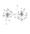
- FIG. 6B is a diagram showing the configuration of the position sensor 24.
- the position sensor 24 includes a rotation roller 24a and a rotation sensor unit 24b.
- the peripheral surface of the rotating roller 24a is in contact with the surface of the cylinder rod 21b, and rotates around the shaft 24c according to the movement of the cylinder rod 21b.
- the stroke amount of the cylinder rod 21b is detected by detecting the rotation amount of the rotating roller 24a.
- the rotation sensor unit 24 b includes a columnar magnet 241 and a Hall IC 242.
- the magnet 241 is provided coaxially with the rotating roller 24a and rotates together with the rotating roller 24a.
- the magnet 241 includes a semi-cylindrical N pole 241a and a semi-cylindrical S pole 241b.
- the Hall IC 242 is a sensor that is provided at a position along the rotation axis of the magnet 241 and detects the magnetic flux density as an electric signal.
- the magnet 241 is rotated by the rotation of the rotating roller 24a, and the magnetic force detected by the Hall IC 242 varies with one rotation as one cycle.
- This magnetic force fluctuation signal is output to the controller 80, and the amount of rotation of the rotating roller 24a is calculated. Thereby, the stroke amount of the cylinder rod 21b is detected, and the rotation angle of the boom 7 is calculated.
- an error may occur due to the slip between the rotating roller 24 a and the cylinder rod 21 b, and this error is corrected based on the angle detected by the rotary encoder 40.
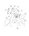
- FIG. 7A is a side view of the first vertical plate 12a as viewed from the left side.
- FIG. 7B is a side view showing a state in which the cover 90 covering the rotary encoder 40 is removed. As shown in FIGS. 3 and 7B, the rotary encoder 40 is fixed to the first vertical plate 12a via a bracket 60.
- the bracket 60 has a first bracket member 61 and a second bracket member 62 as shown in FIG.
- the 1st bracket member 61 is a plate-shaped member, Comprising: It fixes to the part ahead rather than the axis
- the first bracket member 61 is fixed to the outer surface 12s of the first vertical plate 12a (the surface on the opposite side of the second vertical plate 12b) by bolts 63.
- the first bracket member 61 extends upward.
- the second bracket member 62 is a plate-like member, and is fixed to the inner side surface 61a (the surface on the second vertical plate 12b side) of the first bracket member 61 with a bolt 64.
- the second bracket member 62 is disposed on the rear side of the first bracket member 61.
- the rotary encoder 40 is disposed on the inner side surface 62a of the second bracket member 62 (the surface facing the second vertical plate 12b direction).
- the rotary encoder 40 is covered with a cover 90 from the inside as shown in FIG. 7A. Thereby, entry of dirt, dust, etc. can be prevented. Detection of the angle by the rotary encoder 40 is known.
- a detection method for example, a method in which light passing through a slit is received by a light receiving element and an angle is detected based on the timing of light reception can be employed.
- the link member 50 is fixed to the boom 7 via a link fixing member 70 fixed to the side surface of the boom 7. As shown in FIG. 3, the link member 50 includes a first member 51 and a second member 52.
- the first member 51 is an elongated plate-like member. Of the both ends of the first member 51, the first end portion 51 a (see FIG. 3) is connected to the shaft portion 44 of the rotary encoder 40.
- the second member 52 includes a first ball joint 521, a second ball joint 522, and a connection member 523 that connects the first ball joint 521 and the second ball joint 522.
- FIG. 8 is a schematic view of the second member 52 shown in FIG. 3 as viewed from above, and is a partial cross-sectional view of the first ball joint 521 and the second ball joint 522.
- the first ball joint 521 is fixed to the second end 51 b of the first member 51 by a bolt 83 so as to be rotatable.
- the second ball joint 522 is fixed to the link fixing member 70 by a bolt 84.
- the first ball joint 521 has a support portion 521a and a ball portion 521b.
- the support portion 521a is connected to the connection member 523.
- the support portion 521a has a substantially spherical support space 521c formed at the tip, and the ball portion 521b is rotatably supported in the support space 521c.
- a through hole 521d is formed in the ball portion 521b, and a bolt 83 is inserted into the through hole 521d.
- a bolt hole 51c having a thread on the inside is formed in the second end 51b of the first member 51.
- a bolt 83 passing through the through hole 521d is inserted into the bolt hole 51c.
- a washer 85 is disposed between the bolt head 53a of the bolt 83 and the ball portion 521b, and a washer 86 is disposed between the ball portion 521b and the second end portion 51b.
- the second member 52 Since the first ball joint 521 is disposed on the boom 7 side (also referred to as the inner side or the direction toward the second vertical plate 12b) from the second end 51b of the first member 51, the second member 52 is The first member 51 is disposed closer to the boom 7 side. With such a configuration, the first member 51 and the second member 52 are connected to each other so as to be rotatable.
- the axis serving as the rotation center is indicated as 50a in FIGS. 7A, 7B, and 8.
- the link fixing member 70 is a Z-shaped member formed by bending an elongated plate-like member.
- the link fixing member 70 is arrange
- the link fixing member 70 includes a boom side fixing portion 71, a vertical portion 73, a link connecting portion 72, and a rib 75.
- the boom side fixing portion 71 is fixed to the side surface 7 e of the boom 7 with a bolt 74.
- the vertical portion 73 is formed from the rear end of the boom side fixing portion 71 toward the side surface 7e in a substantially vertical direction (right direction).
- the link connecting portion 72 is formed so as to extend from the distal end of the vertical portion 73 toward the base end portion 7 d side of the boom 7.
- the second ball joint 522 has a support portion 522a and a ball portion 522b.
- the support portion 522a is connected to the connection member 523.
- the support portion 522a has a substantially spherical support space 522c formed at the tip, and the ball portion 522b is rotatably supported in the support space 522c.
- a through hole 522d is formed in the ball portion 522b, and a bolt 84 is inserted into the through hole 522d.
- the rib 75 is erected on the outer side surface 72a of the link connecting portion 72 of the link fixing member 70 (the surface on the opposite side of the second vertical plate 12b).
- Bolt holes 75 a are formed in the ribs 75.
- a bolt 84 penetrating through the through hole 522d is inserted into the bolt hole 75a.
- a washer 87 is disposed between the bolt head 84a of the bolt 84 and the ball portion 522b, and a washer 88 is disposed between the ball portion 521b and the second end portion 51b.
- the central axis of the second ball joint 522 is shown as the axis 50b.
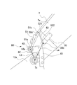
- FIG. 9 is a schematic view of the vicinity of the encoder as seen from the right side.
- the rotary encoder 40 is hidden by the second bracket member 62, but is indicated by a solid line in order to show the positional relationship between the rotary encoder 40, the link member 50, and the shaft 7 s.
- FIGS. 10A and 10B The same applies to FIGS. 10A and 10B.
- the first member 51 when viewed from the right side (perpendicular to the first vertical plate 12 a), the first member 51 includes a shaft 7 s that is a rotating shaft of the boom 7, a second member 52, and a link fixing member
- the length is the same as the line segment La connecting the shaft 50b, which is a connecting portion of 70, and is arranged in parallel with the line segment La.
- the second member 52 has the same length as the line segment Lb connecting the axis 44a that is the center of the shaft portion 44 of the rotary encoder 40 and the axis 7s that is the rotation axis of the boom 7, and is arranged in parallel with the line segment Lb.
- the straight line connecting the shaft 44a, the shaft 7s, the shaft 50b, and the shaft 50a forms a parallelogram.
- 10A and 10B are schematic views showing the state of the link member 50 when the boom 7 is rotated.
- the link member 50 when the boom 7 is in a predetermined position is indicated by a solid line.
- the link member 50 when the boom 7 rotates most upward is indicated by a two-dot chain line.
- the link member 50 when the boom 7 is rotated downward is indicated by a two-dot chain line.
- the link member 50 is kept parallel to the line segment La and the second member 52 is connected to the line segment Lb as the boom 7 rotates. It rotates while keeping parallel.
- the boom 7 When the boom 7 is rotated, it is obtained by connecting the shaft 44a, the shaft 7s, the shaft 50b, and the shaft 50a in a straight line in order when viewed from the right side surface (perpendicular to the first vertical plate 12a).
- the square always maintains a parallelogram.
- the second end portion 51b of the first member 51 connected to the second member 52 rotates on the circumference (one-dot chain line) around the first end portion 51a that is a connection portion with the rotary encoder 40. To do.
- the first member 51 is kept parallel to the line segment La, and the second member 52 is kept parallel to the line segment Lb.
- the rotation angle of the first member 51 corresponds to one to one.
- the rotation angle of the first member 51 when the boom 7 is rotated upward from the predetermined position is indicated by ⁇ in FIG. 10A, and the rotation angle of the boom 7 at that time is also ⁇ .
- the rotation angle of the first member 51 when the boom 7 is rotated downward from the predetermined position is indicated by ⁇ in FIG. 10B, and the rotation angle of the boom 7 at that time is also ⁇ .
- the link member 50 also moves as the boom 7 rotates.
- the rotation angle of the first member 51 of the link member 50 corresponds to the rotation angle of the rotation of the boom 7 in a pair.
- the hydraulic excavator 100 (an example of a work vehicle) according to the above embodiment includes a turning frame 10 (an example of a frame), a boom 7, a rotary encoder 40 (an example of an angle detector), and a link member 50.
- the swivel frame 10 has a pair of first vertical plate 12a and second vertical plate 12b facing each other.
- the boom 7 is rotatably supported by the first vertical plate 12a and the second vertical plate 12b.
- the rotary encoder 40 is provided at a position different from the shaft 7s (an example of a rotating shaft).
- the link member 50 transmits the rotation angle of the boom 7 to the rotary encoder 40 according to the rotation of the boom 7.
- the rotary encoder 40 can be installed at a position different from the axis 7s that is the rotation axis of the boom 7. Thereby, the position of the rotary encoder 40 can be moved from the rotating shaft of the boom 7 according to the components arranged in the vicinity of the shaft 7 s that is the rotation center of the boom 7. For this reason, the space on the shaft 7s side of the boom 7 (outside the first vertical plate 12a) can be effectively utilized.
- the rotary encoder 40 is disposed above the shaft 7s.
- the components can be arranged close to the side of the first vertical plate 12a, so that the space on the side of the shaft 7s (outside of the first vertical plate 12a) can be effectively utilized.
- the excavator 100 of the above embodiment further includes a reducing agent tank 15 (an example of a tank).
- the reducing agent tank 15 is disposed on the revolving frame 10 and on the side of the first vertical plate 12a.
- the rotary encoder 40 is disposed above the reducing agent tank 15. Thereby, tanks such as the reducing agent tank 15 and the fuel tank can be arranged close to the side of the first vertical plate 12a, so that the space outside the first vertical plate 12a can be effectively used.
- the excavator 100 of the above embodiment further includes a bracket 60 (an example of a support member).
- the bracket 60 is a plate-like member that is fixed to the first vertical plate 12 a and supports the rotary encoder 40.
- the rotary encoder 40 is disposed on the second vertical plate 12 b side of the bracket 60.
- components such as the reducing agent tank 15 can be arranged close to the outside of the first vertical plate 12a. The space outside the first vertical plate 12a can be used effectively.
- the link member 50 includes the first member 51 coupled to the rotary encoder 40 and the second member 52 coupled to the boom 7.
- the 1st member 51 and the 2nd member 52 are connected so that rotation is mutually possible.
- the first member 51 is disposed in parallel to a straight line La connecting the shaft 50b (an example of a connecting portion between the second member and the boom) and the shaft 7s (an example of a rotating shaft of the boom). It arrange
- a parallel link can be comprised, the rotation angle of the boom 7 and the angle detected by the rotary encoder 40 can be corresponded one to one, and the rotation angle of the boom 7 and the detection angle by the rotary encoder 40 can be made the same value.
- the parallelism allows a mechanical error and includes a mechanical error and has a spread.
- the link member 50 is connected to the boom 7 via the link fixing member 70, but the link member 50 is directly connected to the boom 7 depending on the distance between the link member 50 and the side surface of the boom 7. May be.
- the first member 51 is connected to the rotary encoder 40 at the first end portion 51a and connected to the second member 52 at the second end portion 51b. Further, it may extend beyond the connecting portion between the rotary encoder 40 and the second member 52.
- the bracket 60 is configured by connecting two members, the first bracket member 61 and the second bracket member 62, but may be a single member.
- the structure of the first bracket member 61 to which the rotary encoder 40 is attached is more complicated than the second bracket member 62.
- the first bracket member 61 is used as a common component, and the size of the second bracket member 62, which is a plate-like member, can be easily applied to work vehicles of different types or sizes.
- FIG. 11 is a diagram illustrating a state in which the rotary encoder 40 is attached to the first vertical plate 12a ′.
- the first vertical plate 12a ′ shown in FIG. 11 is formed to extend upward as compared with the first vertical plate 12a of the first embodiment, and the inner side of the first vertical plate 12a ′ (second vertical plate 12b).
- the rotary encoder 40 is attached to the surface 12s ′.
- the link member 50 of the present invention is applied to the rotary encoder 40 (an example of an angle detector) for calibrating the position sensor 24 of the boom cylinder 21, but provided on the shaft 8 a of the arm 8.
- the present invention may be applied to the rotary encoder.
- an example of the rotating member corresponds to the arm 8
- an example of the frame corresponds to the boom 7.
- the rotary encoder 40 for calibrating the position sensor 24 has been described.
- the rotary encoder 40 for calibrating the position sensor 24 is not limited, and in short, the rotation angle of the rotating member. It may be a rotary encoder for detecting.
- the work vehicle of the present invention has an effect of effectively utilizing the space outside the vertical plate and can be applied to a hydraulic excavator or the like.
Landscapes
- Engineering & Computer Science (AREA)
- Mining & Mineral Resources (AREA)
- Civil Engineering (AREA)
- General Engineering & Computer Science (AREA)
- Structural Engineering (AREA)
- Mechanical Engineering (AREA)
- Component Parts Of Construction Machinery (AREA)
- Operation Control Of Excavators (AREA)
Abstract
Description
例えば、特許文献1では、ブームを回動させる油圧シリンダに、ストローク長を検出可能なシリンダが用いられている。
このシリンダは、油圧シリンダのストローク位置をシリンダロッド上の回転ローラの回転により検出する構成である。この回転ローラとシリンダロッドとの間では微小な滑りが生じるため、位置センサの検出結果から得られるストローク長と実際のストローク長との間に誤差が生じる。その誤差を補正するために、ブームの回転軸に角度検出器の一例としてロータリエンコーダが設けられている。ロータリエンコーダによってブームの角度が予め決定された基準角度になった時点を検出し、シリンダで生じる誤差が補正されている。
しかしながら、ブームの回転軸にロータリエンコーダを設ける場合、ロータリエンコーダは、ブームを支持するフレームの縦板の外側に配置されることになる。このため、ロータリエンコーダが縦板から外側に突出することになり、ロータリエンコーダを縦板の外側に配置した場合、縦板の側方に配置される構成部品に干渉する可能性があり、構成部品の配置位置が制限される。従って、構成部品によっては、縦板の外側に配置することが出来ず、縦板の外側のスペースを有効活用できない場合がある。
本発明の目的は、縦板の外側のスペースを有効活用できる作業車両を提供することである。
第1の発明に係る作業車両は、フレームと、ブームと、角度検出器と、リンク部材とを備える。フレームは、互いに対向した一対の第1縦板および第2縦板を有する。ブームは、第1縦板および第2縦板に回動可能に支持される。角度検出器は、ブームの回転軸と異なる位置に設けられる。リンク部材は、ブームの回動に応じてブームの回転角度を角度検出器に伝達する。
また、近年エンジンからの排気ガスを処理する排気処理装置を作業車両に搭載することが要望されている。その場合、上部旋回体に還元剤タンクを設置するスペースを確保する必要があるが、上述の作業車両では、第1縦板の外側のスペースに還元剤タンクを設置できる。
これによって、第1縦板の側方に近接して構成部品を配置できるため、第1縦板の外側のスペースを有効活用できる。
これによって、第1縦板の側方に近接して、還元剤タンクや燃料タンク等のタンクを配置できるため、第1縦板の外側のスペースを有効活用できる。
これによって、第1縦板の側方に近接して還元剤タンクを配置できる。
このように、角度検出器を支持部材の第2縦板側に配置しているため、第1縦板の外側に近接して還元剤タンク等の構成部品を配置することが出来、第1縦板の外側のスペースを有効活用できる。
このように、角度検出器を第1縦板の第2縦板側に配置しているため、第1縦板の外側に近接して還元剤タンク等の構成部品を配置することが出来、第1縦板の外側のスペースを有効活用できる。
これにより、平行リンクが構成され、ブームの回転角度と角度検出器によって検出される角度が一対一に対応し、ブームの回転角度と角度検出器による検出角度が同じ値となる。
上記平行は、機械的な誤差を許容するもので、機械的な誤差を含み広がりがある。
本発明によれば、縦板の外側のスペースを有効活用可能な作業車両を提供することができる。
<1.構成>
(1-1.油圧ショベルの全体構成)
図1は、本発明の実施の形態に係る油圧ショベル100を示す図である。この油圧ショベル100は、車両本体1と、作業機4とを備えている。
旋回体3は、走行体2上に載置されている旋回フレーム10を有し、走行体2に対して旋回可能に設けられている。旋回体3の前部左側位置であって、旋回フレーム10の上側には運転室としてのキャブ5が設けられている。
尚、全体構成の説明において、前後方向とは、キャブ5の前後方向を意味する。車両本体1の前後方向は、キャブ5、すなわち旋回体3の前後方向と一致するものとする。左右方向、或いは側方とは、車両本体1の車幅方向を意味する。
作業機4は、ブーム7、アーム8、掘削バケット9を有し、旋回体3の前部中央位置に取り付けられている。作業機4は、キャブ5の右側面5aの右側に配置されている。ブーム7の基端部は、旋回体3に回動可能に連結されている。ブーム7の先端部はアーム8の基端部に回動可能に連結されている。アーム8の先端部は、掘削バケット9に回動可能に連結されている。
図2Aは、図1に示す油圧ショベル100を前方側から見た部分正面図である。なお、図2Aでは、ブームシリンダ21、21´、キャブ5等が省略されている。図2Bは、図2Aの側面図である。図3は、ブーム7の基端部近傍を示す部分拡大図である。なお、図3では、説明のために後述の還元剤タンク15が省略されている。
図1、図2A、および図2Bに示すように、第1縦板12aの右側には、第1縦板12aに近接して還元剤タンク15が設けられている。還元剤タンク15の一部は軸7sと同じ高さに位置している。側面視において還元剤タンク15は、軸7sに重なるように配置されている。
還元剤タンク15には、エンジンからの排気中の窒素酸化物を低減するために用いられる還元剤の前駆体が貯留される。なお、本明細書では、還元剤の前駆体を単に「還元剤」と称する。還元剤としては、例えば尿素水が挙げられる。
図4及び図5に示すように、還元剤タンク15は、タンク本体15aと、給水口15bと、タンク本体15aと給水口15bを覆う開閉可能なカバー15cとを有している。給水口15bは、タンク本体15aの左側に位置している。給水口15bから供給された還元剤がタンク本体15aに貯留される。カバー15cは、後端側を支点にして、前側が上下に回動可能に構成されている。
図6Aは、ブームシリンダ21の構成を模式的に示す図である。本実施の形態の油圧ショベル100に用いられているブームシリンダ21は、シリンダロッド21bのストロークを検出可能なシリンダである。なお、図1に示すように、ブーム7を挟んで2つのシリンダが設けられており、少なくとも一方のシリンダがストロークを検出可能なシリンダであればよい。本実施の形態では、右側にストロークを検出可能なブームシリンダ21が設けられており、左側にストローク検出機能(後述する位置センサ24)を有していないブームシリンダ21´が設けられている。
ピストン21cは、シリンダチューブ21a内に摺動可能に配置されている。ピストン21cは、シリンダロッド21bと固定されている。シリンダロッド21bの先端21hは、ブーム7の略中央に設けられているシリンダ連結部7aに回転可能に連結されている。シリンダチューブ21aの下端21iは、図2Aに示すシリンダ連結板13aに回動可能に固定されている。図2Aに示すように、シリンダ連結板13aは、底板11の前端中央近傍に立設して配置されている。なお、シリンダ連結板13aに対向して、底板11からシリンダ連結板13bが立設している。このシリンダ連結板13bには、ブームシリンダ21´のシリンダチューブの下端が配置される。
シリンダチューブ21aには、図示しない油圧ポンプから第1空間21dに作動油を供給する第1供給口21fと、油圧ポンプから第2空間21eに作動油を供給する第2供給口21gとが形成されている。
上記ブームシリンダ21では、回転ローラ24aとシリンダロッド21bの間の滑りによって誤差が生じる場合があり、この誤差がロータリエンコーダ40によって検出された角度に基づいて補正される。
図7Aは、第1縦板12aを左側から見た側面図である。図7Bは、ロータリエンコーダ40を覆うカバー90を外した状態を示す側面図である。
図3および図7Bに示すように、ロータリエンコーダ40は、第1縦板12aにブラケット60を介して固定されている。
ロータリエンコーダ40は、第2ブラケット部材62の内側面62a(第2縦板12b方向を向いた面)に配置されている。ロータリエンコーダ40は、図7Aに示すように内側からカバー90で覆われている。これにより、土、埃などの進入を防止することができる。
ロータリエンコーダ40による角度の検出は、公知である。検出方式としては、例えば、スリットを通過する光を受光素子で受光し、受光のタイミングに基づいて角度を検出する方式を採用することができる。
図3に示すように、リンク部材50は、ブーム7の側面に固定されているリンク固定部材70を介して、ブーム7に固定されている。図3に示すように、リンク部材50は、第1部材51と、第2部材52とを有している。
第1部材51は、細長い板状の部材である。第1部材51の両端のうち第1端部51a(図3参照)は、ロータリエンコーダ40の軸部44に接続されている。
第2部材52は、第1ボールジョイント521と、第2ボールジョイント522と、第1ボールジョイント521と第2ボールジョイント522と繋ぐ接続部材523とを有している。
図8は、図3に示す第2部材52を上方から見た模式図であり、第1ボールジョイント521と第2ボールジョイント522の部分断面図である。
第1ボールジョイント521が、第1部材51の第2端部51bに、ボルト83によって回動可能に固定されている。第2ボールジョイント522は、リンク固定部材70にボルト84によって固定されている。
このような構成により、第1部材51と第2部材52は互いに回動可能に連結されている。この回動中心となる軸が、図7A、図7Bおよび図8において50aとして示されている。
リンク固定部材70は、図3に示すように、細長い板状の部材を曲げて形成したZ形状の部材である。リンク固定部材70は、第1ブーム部7bの側面7eに、第1ブーム部7bの長手方向に沿うように配置されている。リンク固定部材70は、ブーム側固定部71と、垂直部73と、リンク接続部72と、リブ75とを有する。
第2ボールジョイント522は、図8に示すように支持部522aと、ボール部522bとを有している。支持部522aは、接続部材523に接続されている。支持部522aには、先端部分に略球形状の支持空間522cが形成されており、支持空間522c内にボール部522bが回転可能に支持されている。ボール部522bには、貫通孔522dが形成されており、貫通孔522dにボルト84が挿入されている。
第2ボールジョイント522の中心軸は軸50bとして図示されている。
図9は、エンコーダ近傍を右側面からみた模式図である。図9では、ロータリエンコーダ40は、第2ブラケット部材62によって隠れているが、ロータリエンコーダ40、リンク部材50および軸7sの配置関係を示すために実線で記載している。以下、図10Aおよび図10Bにおいても同様である。
第2部材52は、ロータリエンコーダ40の軸部44の中心である軸44aと、ブーム7の回転軸である軸7sとを結ぶ線分Lbと同じ長さであり、線分Lbと平行に配置されている。
図10Aおよび図10Bは、ブーム7が回動した際のリンク部材50の状態を示す模式図である。図10Aおよび図10Bには、ブーム7が所定の位置のときのリンク部材50が実線で示されている。図10Aでは、ブーム7が最も上方に回動した際のリンク部材50が二点鎖線で示されている。図10Bでは、ブーム7が最も下方に回動した際のリンク部材50が二点鎖線で示されている。
図10Aおよび図10Bに示すように、ブーム7が回動すると、ブーム7の回動とともにリンク部材50は、第1部材51が線分Laと平行を保ち、第2部材52が線分Lbと平行を保ちながら回動する。ブーム7の回動の際、右側面側(第1縦板12aに対して垂直方向)から見て、軸44aと、軸7sと、軸50bと、軸50aとを順に直線で結んで得られる四角形は常に平行四辺形を保っている。このとき、第2部材52と連結されている第1部材51の第2端部51bは、ロータリエンコーダ40との連結部分である第1端部51aを中心に円周(一点鎖線)上を回転する。
上記所定の位置からブーム7が最も上方に回動した際の第1部材51の回動角度が図10Aにおいてαと示されており、そのときのブーム7の回動角度もαとなる。上記所定の位置からブーム7が最も下方に回動した際の第1部材51の回動角度が図10Bにおいてβと示されており、そのときのブーム7の回動角度もβとなる。
油圧ショベル100の動作時に、ブーム7が上下方向に回動すると、ブーム7の回動に伴ってリンク部材50も動く。上述のようにリンク部材50の第1部材51の回転角度は、ブーム7の回動の回転角度と一対一対に対応する。
(3-1)
上記実施の形態の油圧ショベル100(作業車両の一例)は、旋回フレーム10(フレームの一例)と、ブーム7と、ロータリエンコーダ40(角度検出器の一例)と、リンク部材50とを備える。旋回フレーム10は、互いに対向した一対の第1縦板12aおよび第2縦板12bを有する。ブーム7は、第1縦板12aおよび第2縦板12bに回動可能に支持される。ロータリエンコーダ40は、軸7s(回転軸の一例)と異なる位置に設けられる。リンク部材50は、ブーム7の回動に応じてブーム7の回転角度をロータリエンコーダ40に伝達する。
上記実施の形態の油圧ショベル100では、ロータリエンコーダ40は、軸7sより上方に配置されている。
これによって、第1縦板12aの側方に近接して構成部品を配置できるため、軸7sの側方(第1縦板12aの外側)のスペースを有効活用できる。
上記実施の形態の油圧ショベル100は、還元剤タンク15(タンクの一例)を更に備える。還元剤タンク15は、旋回フレーム10上であって第1縦板12aの側方に配置されている。ロータリエンコーダ40は、還元剤タンク15よりも上方に配置されている。
これによって、第1縦板12aの側方に近接して、還元剤タンク15や燃料タンク等のタンクを配置できるため、第1縦板12aの外側のスペースを有効活用できる。
上記実施の形態の油圧ショベル100は、ブラケット60(支持部材の一例)を更に備えている。ブラケット60は、第1縦板12aに固定され、ロータリエンコーダ40を支持する板状の部材である。ロータリエンコーダ40は、ブラケット60の第2縦板12b側に配置されている。
このように、ロータリエンコーダ40をブラケット60の第2縦板12b側に配置しているため、第1縦板12aの外側に近接して還元剤タンク15等の構成部品を配置することが出来、第1縦板12aの外側のスペースを有効活用できる。
上記実施の形態の油圧ショベル100では、リンク部材50は、ロータリエンコーダ40と連結された第1部材51と、ブーム7と連結された第2部材52と、を有する。第1部材51と第2部材52は、互いに回動可能に連結されている。第1部材51は、軸50b(第2部材とブームとの連結部分の一例)と、軸7s(ブームの回転軸の一例)とを結ぶ直線Laに平行に配置され、第2部材52は、軸44a(角度検出器と第1部材との連結部分の一例)と、軸7s(ブームの回転軸の一例)とを結ぶ直線Lbに平行に配置されている。
上記平行は、機械的な誤差を許容するもので、機械的な誤差を含み広がりがある。
以上、本発明の一実施形態について説明したが、本発明は上記実施形態に限定されるものではなく、発明の要旨を逸脱しない範囲で種々の変更が可能である。
(A)
上記実施の形態では、リンク部材50は、リンク固定部材70を介してブーム7と連結されているが、リンク部材50とブーム7の側面の間の距離によってはリンク部材50がブーム7に直接連結されていてもよい。
(B)
上記実施の形態では、第1部材51は、第1端部51aでロータリエンコーダ40と連結し、第2端部51bで第2部材52と連結していたが、端で連結しなくてもよく、ロータリエンコーダ40および第2部材52との連結部分よりも延びていてもよい。
上記実施の形態では、ブラケット60は、第1ブラケット部材61と第2ブラケット部材62の2つの部材が連結されて構成されているが、1つの部材であってもよい。なお、2つの部材に分けることによって、種類または大きさの異なる作業車両に適用しやすい。詳細には、ロータリエンコーダ40が取り付けられる第1ブラケット部材61の構造は第2ブラケット部材62と比較して複雑である。このため、第1ブラケット部材61を共通部品とし、板状の部材である第2ブラケット部材62の大きさを変更することによって、種類または大きさの異なる作業車両に簡単に適用できる。
上記実施の形態では、ロータリエンコーダ40は、第1縦板12aに固定されたブラケット60に取り付けられているが、第1縦板に直接取り付けられていてもよい。図11は、ロータリエンコーダ40が第1縦板12a´に取り付けられている状態を示す図である。図11に示す第1縦板12a´は、上記実施の形態1の第1縦板12aと比較して上方に延びて形成されており、第1縦板12a´の内側(第2縦板12b側)の面12s´にロータリエンコーダ40が取り付けられている。
上記実施の形態では、ブームシリンダ21の位置センサ24の較正を行うためのロータリエンコーダ40(角度検出器の一例)について、本発明のリンク部材50を適用したが、アーム8の軸8aに設けられているロータリエンコーダに対して本発明を適用してもよい。この場合、回動部材の一例は、アーム8に対応し、フレームの一例は、ブーム7に対応する。
上記実施の形態では、位置センサ24の較正を行うためのロータリエンコーダ40について説明したが、位置センサ24の較正を行うためのロータリエンコーダ40に限らなくてもよく、要するに、回動部材の回転角度を検出するためのロータリエンコーダであってもよい。
上記実施の形態では、作業車両の一例として油圧ショベルを用いてロータリエンコーダ40およびリンク部材50の説明を行ったが、油圧ショベルに限らず、他の作業車両に適用してもよい。
7s 軸(ブームの回転軸の一例)
10 旋回フレーム
11 底板
12a 第1縦板
12b 第2縦板
40 ロータリエンコーダ(角度検出器の一例)
50 リンク部材
Claims (7)
- 互いに対向した第1縦板および第2縦板を有するフレームと、
前記第1縦板および前記第2縦板に回動可能に支持されたブームと、
前記ブームの回転軸と異なる位置に設けられる角度検出器と、
前記ブームの回動に応じて前記ブームの回転角度を前記角度検出器に伝達するリンク部材と、
を備えた作業車両。 - 前記角度検出器は、前記回転軸より上方に配置されている、
請求項1に記載の作業車両。 - 前記フレーム上であって前記第1縦板の側方に配置されたタンクを更に備え、
前記角度検出器は、前記タンクよりも上方に配置されている、
請求項1に記載の作業車両。 - 前記タンクは、還元剤タンクである、
請求項3に記載の作業車両。 - 前記第1縦板に固定され、前記角度検出器を支持する板状の支持部材を更に備え、
前記角度検出器は、前記支持部材の前記第2縦板側に配置されている、
請求項1に記載の作業車両。 - 前記角度検出器は、前記第1縦板の前記第2縦板側に配置されている、
請求項1に記載の作業車両。 - 前記リンク部材は、
前記角度検出器と連結された第1部材と、
前記ブームと連結された第2部材と、を有し、
前記第1部材と前記第2部材は、互いに回動可能に連結されており、
前記第1部材は、前記第2部材と前記ブームとの連結部分と、前記ブームの回転軸とを結ぶ直線に平行に配置され、
前記第2部材は、前記角度検出器と前記第1部材との連結部分と、前記ブームの回転軸とを結ぶ直線に平行に配置されている、
請求項1に記載の作業車両。
Priority Applications (6)
| Application Number | Priority Date | Filing Date | Title |
|---|---|---|---|
| PCT/JP2015/052581 WO2016121069A1 (ja) | 2015-01-29 | 2015-01-29 | 作業車両 |
| KR1020157012601A KR101755361B1 (ko) | 2015-01-29 | 2015-01-29 | 작업 차량 |
| DE112015000013.5T DE112015000013T5 (de) | 2015-01-29 | 2015-01-29 | Arbeitsfahrzeug |
| US14/771,244 US9909282B2 (en) | 2015-01-29 | 2015-01-29 | Work vehicle |
| CN201580000107.9A CN105980636B (zh) | 2015-01-29 | 2015-01-29 | 作业车辆 |
| JP2015510208A JP6294305B2 (ja) | 2015-01-29 | 2015-01-29 | 作業車両 |
Applications Claiming Priority (1)
| Application Number | Priority Date | Filing Date | Title |
|---|---|---|---|
| PCT/JP2015/052581 WO2016121069A1 (ja) | 2015-01-29 | 2015-01-29 | 作業車両 |
Publications (1)
| Publication Number | Publication Date |
|---|---|
| WO2016121069A1 true WO2016121069A1 (ja) | 2016-08-04 |
Family
ID=56542720
Family Applications (1)
| Application Number | Title | Priority Date | Filing Date |
|---|---|---|---|
| PCT/JP2015/052581 Ceased WO2016121069A1 (ja) | 2015-01-29 | 2015-01-29 | 作業車両 |
Country Status (6)
| Country | Link |
|---|---|
| US (1) | US9909282B2 (ja) |
| JP (1) | JP6294305B2 (ja) |
| KR (1) | KR101755361B1 (ja) |
| CN (1) | CN105980636B (ja) |
| DE (1) | DE112015000013T5 (ja) |
| WO (1) | WO2016121069A1 (ja) |
Families Citing this family (4)
| Publication number | Priority date | Publication date | Assignee | Title |
|---|---|---|---|---|
| US11401711B2 (en) | 2017-03-31 | 2022-08-02 | James Alan Klein | Multilayer fire safety tape and related fire retardant building construction framing members |
| CN112179547B (zh) * | 2020-08-12 | 2022-05-24 | 上汽通用五菱汽车股份有限公司 | 六分力传感器旋转式应用装置 |
| US12467239B2 (en) | 2022-05-25 | 2025-11-11 | Caterpillar Inc. | Machine with a boom link and position sensor |
| EP4296434B1 (en) * | 2022-06-22 | 2026-05-06 | Leica Geosystems Technology A/S | Improved determination of an excavator swing boom angle based on intermittent first interim swing boom angles |
Citations (2)
| Publication number | Priority date | Publication date | Assignee | Title |
|---|---|---|---|---|
| JP2004278288A (ja) * | 2003-02-26 | 2004-10-07 | Shin Caterpillar Mitsubishi Ltd | 建設機械におけるアーム角度センサ装置 |
| JP2014214539A (ja) * | 2013-04-26 | 2014-11-17 | 日立建機株式会社 | 作業機のフロント角度検出装置 |
Family Cites Families (7)
| Publication number | Priority date | Publication date | Assignee | Title |
|---|---|---|---|---|
| JP3900449B2 (ja) | 1998-12-08 | 2007-04-04 | 株式会社小松製作所 | 油圧ショベルのアーム角度検出器取付構造 |
| CN1748062A (zh) * | 2003-02-26 | 2006-03-15 | 新卡特彼勒三菱株式会社 | 建筑机械中臂角度传感器装置 |
| JP5562777B2 (ja) * | 2010-09-16 | 2014-07-30 | 日立建機株式会社 | 建設機械 |
| CN202577387U (zh) * | 2011-12-24 | 2012-12-05 | 广西玉柴重工有限公司 | 挖掘机角度测量工作装置 |
| JP5761148B2 (ja) * | 2012-09-26 | 2015-08-12 | コベルコ建機株式会社 | 建設機械の角度検出装置 |
| JP5401616B1 (ja) | 2013-01-18 | 2014-01-29 | 株式会社小松製作所 | 油圧ショベルおよび油圧ショベルの油圧シリンダのストローク計測方法 |
| JP5629015B1 (ja) * | 2013-02-18 | 2014-11-19 | 株式会社小松製作所 | 油圧ショベル |
-
2015
- 2015-01-29 DE DE112015000013.5T patent/DE112015000013T5/de active Pending
- 2015-01-29 KR KR1020157012601A patent/KR101755361B1/ko not_active Expired - Fee Related
- 2015-01-29 JP JP2015510208A patent/JP6294305B2/ja not_active Expired - Fee Related
- 2015-01-29 CN CN201580000107.9A patent/CN105980636B/zh not_active Expired - Fee Related
- 2015-01-29 WO PCT/JP2015/052581 patent/WO2016121069A1/ja not_active Ceased
- 2015-01-29 US US14/771,244 patent/US9909282B2/en not_active Expired - Fee Related
Patent Citations (2)
| Publication number | Priority date | Publication date | Assignee | Title |
|---|---|---|---|---|
| JP2004278288A (ja) * | 2003-02-26 | 2004-10-07 | Shin Caterpillar Mitsubishi Ltd | 建設機械におけるアーム角度センサ装置 |
| JP2014214539A (ja) * | 2013-04-26 | 2014-11-17 | 日立建機株式会社 | 作業機のフロント角度検出装置 |
Also Published As
| Publication number | Publication date |
|---|---|
| DE112015000013T5 (de) | 2016-11-10 |
| JPWO2016121069A1 (ja) | 2017-04-27 |
| KR101755361B1 (ko) | 2017-07-07 |
| US20160362872A1 (en) | 2016-12-15 |
| CN105980636A (zh) | 2016-09-28 |
| US9909282B2 (en) | 2018-03-06 |
| CN105980636B (zh) | 2019-05-03 |
| KR20160106483A (ko) | 2016-09-12 |
| JP6294305B2 (ja) | 2018-03-14 |
Similar Documents
| Publication | Publication Date | Title |
|---|---|---|
| JP7422909B2 (ja) | 作業車両 | |
| JP6294305B2 (ja) | 作業車両 | |
| CN111183551A (zh) | 作业车辆用天线单元以及作业车辆 | |
| JP7596469B2 (ja) | 作業車両 | |
| WO2016047166A1 (ja) | 運搬車両 | |
| WO2013047180A1 (ja) | 建設機械 | |
| JP7615375B2 (ja) | 作業車両 | |
| JP6484595B2 (ja) | 作業車両 | |
| WO2017158779A1 (ja) | アンテナの取付構造およびダンプトラック | |
| JP2012166778A (ja) | 車両における懸架システムのための変位計測システムおよび方法 | |
| CN112993537A (zh) | 作业车辆用天线单元以及作业车辆 | |
| JP2018184783A (ja) | 電気駆動式作業機械のケーブルブラケット | |
| WO2019176314A1 (ja) | 旋回作業車、及び、旋回作業車における施工端部の位置検知方法 | |
| US20140367528A1 (en) | Construction machine | |
| JP7229109B2 (ja) | 作業機械および作業機械の制御方法 | |
| JP7746224B2 (ja) | 旋回作業機、及び旋回作業機の方位検出方法 | |
| JP2006058049A (ja) | 車載用装置 | |
| JP2006266039A (ja) | 旋回作業機 | |
| JP2001213364A (ja) | 作業機の走行装置 | |
| JP2000292143A (ja) | トンネル掘進機の後胴と前胴との相対姿勢計測装置 | |
| JP2015129417A (ja) | 建設機械 |
Legal Events
| Date | Code | Title | Description |
|---|---|---|---|
| ENP | Entry into the national phase |
Ref document number: 2015510208 Country of ref document: JP Kind code of ref document: A |
|
| ENP | Entry into the national phase |
Ref document number: 20157012601 Country of ref document: KR Kind code of ref document: A |
|
| WWE | Wipo information: entry into national phase |
Ref document number: 112015000013 Country of ref document: DE Ref document number: 1120150000135 Country of ref document: DE |
|
| WWE | Wipo information: entry into national phase |
Ref document number: 14771244 Country of ref document: US |
|
| 121 | Ep: the epo has been informed by wipo that ep was designated in this application |
Ref document number: 15879966 Country of ref document: EP Kind code of ref document: A1 |
|
| 122 | Ep: pct application non-entry in european phase |
Ref document number: 15879966 Country of ref document: EP Kind code of ref document: A1 |