WO2016121043A1 - ネットワークシステム、アドレス管理装置及びアドレス管理方法 - Google Patents
ネットワークシステム、アドレス管理装置及びアドレス管理方法 Download PDFInfo
- Publication number
- WO2016121043A1 WO2016121043A1 PCT/JP2015/052435 JP2015052435W WO2016121043A1 WO 2016121043 A1 WO2016121043 A1 WO 2016121043A1 JP 2015052435 W JP2015052435 W JP 2015052435W WO 2016121043 A1 WO2016121043 A1 WO 2016121043A1
- Authority
- WO
- WIPO (PCT)
- Prior art keywords
- address
- communication device
- ipv6
- network system
- mac
- Prior art date
Links
Images


Classifications
-
- H—ELECTRICITY
- H04—ELECTRIC COMMUNICATION TECHNIQUE
- H04L—TRANSMISSION OF DIGITAL INFORMATION, e.g. TELEGRAPHIC COMMUNICATION
- H04L12/00—Data switching networks
- H04L12/28—Data switching networks characterised by path configuration, e.g. LAN [Local Area Networks] or WAN [Wide Area Networks]
Definitions
- This invention relates to an IPv6 (Internet Protocol Version 6) address management technology.
- IPv6 Internet Protocol Version 6
- IoT Internet of Things
- IoT In IoT, not only communication devices such as PCs that have been connected to the Internet so far, but also various other devices are connected to the Internet as communication devices. Therefore, if IoT becomes widespread, more communication devices than before will be connected to the Internet.
- a communication device connected to the Internet needs to be assigned an IP address that can uniquely identify the communication device on the Internet.
- IPv4 Internet Protocol Version 4
- IPv6 Internet Protocol Version 6
- An IPv6 address that is an IP address in IPv6 is 128 bits. Therefore, it can be considered that IPv6 addresses will not be exhausted.
- Patent Document 1 describes that a building name or the like is assigned to some bits of an IPv6 address of a communication device.
- IPv6 it is effective to spread IPv6 in order to spread IoT.
- the existing network configuration has a complicated structure using a large number of two-layer switches, and an IPv6 address automatic setting technique called plug and play in IPv6 cannot be applied. This is one of the reasons why IPv6 is not popularized.
- Patent Document 1 only describes the configuration of an IPv6 address, and does not describe a method for setting an IPv6 address in a communication device.
- An object of the present invention is to simplify the management of a communication device while making it possible to automatically set an IPv6 address for the communication device even in an existing network configuration.
- the network system includes: A network system using IPv6 (Internet Protocol Version 6), A communication device that transmits a router solicitation message including a MAC (Media Access Control) address; An address management device provided for each multicast-capable range, corresponding to a MAC address included in a router solicitation message transmitted by the communication device, from correspondence information in which location information indicating an installation location is associated with each MAC address And an address management device that generates an IPv6 address using the acquired position information, and transmits the generated IPv6 address to the communication device on a router advertisement message.
- IPv6 Internet Protocol Version 6
- a communication device that transmits a router solicitation message including a MAC (Media Access Control) address
- An address management device provided for each multicast-capable range, corresponding to a MAC address included in a router solicitation message transmitted by the communication device, from correspondence information in which location information indicating an installation location is associated with each MAC address
- an address management device that generates an IPv6 address using the acquired position information, and transmits the generated IPv
- the address management device provided for each multicast-capable range when the address management device provided for each multicast-capable range receives the router solicitation message, it generates an IPv6 address, and transmits the generated IPv6 address on the router advertisement message to the communication device.
- an IPv6 address can be automatically set for a communication device even in an existing network configuration.
- an IPv6 address is generated from position information corresponding to the MAC address. As a result, it is possible to collectively manage the installation position and the IP address of the communication device, and the management of the communication device can be simplified.
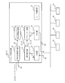
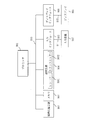
- FIG. 1 is an overall configuration diagram of a network system 10 according to a first embodiment.
- FIG. 3 is a configuration diagram of the address management device 20 when the address management device 20 is a router 17.
- the block diagram of the address management apparatus 20 in case the address management apparatus 20 is the exclusive device 19.
- FIG. Explanatory drawing of the correspondence information 40 and IPv6 address which concern on Embodiment 1.
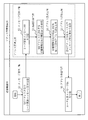
- FIG. 3 is a flowchart showing the operation of the network system 10 according to the first embodiment.
- FIG. 3 is an overall configuration diagram of a network system 10 according to a second embodiment. Explanatory drawing of the correspondence information 40 and IPv6 address which concern on Embodiment 2.
- FIG. FIG. 3 is a diagram illustrating a hardware configuration example of an address management device 20, a communication device 30, and a sub communication device 31 according to the first and second embodiments.
- Embodiment 1 FIG. *** Explanation of premise *** First, plug and play in IPv6 will be described.
- the communication device is assigned a MAC (Media Access Control) address.
- the MAC address is 48 bits. Therefore, there are theoretically 281,474,976,710,656 MAC addresses, and there is almost no possibility of exhaustion at the present time.
- the MAC address is unique for each communication device.
- IPv6 has a procedure for making a stateless association between IPv6 and a MAC address by utilizing the unique MAC address.
- a prefix value is set in the upper 64 bits of the 128-bit IPv6 address.
- the lower 64 bits the upper 16 bits of the MAC address, the padding 16 bits, and the lower 32 bits of the MAC address are set in order.
- the IPv6 address determined by the above procedure is set in the communication device, and the communication device is intended to be capable of IP communication.
- IPv6 has three types of addresses: a global address, a site local address, and a link local address.
- the global address is a unique address among all IPv6 addresses. By using the global address, it is possible to communicate with all the communication devices connected to the IPv6 network.
- the site local address is an address used by being closed in the organization, and is a unique address in the organization. When site local address is used, it is not possible to communicate outside the specified organization.
- the link local address is an address that is closed and used in the second layer network according to an OSI (Open Systems Interconnection) reference model that can be multicast, and is a unique address in the second layer network.
- OSI Open Systems Interconnection
- the second layer network such as a bus type, ring type, repeater hub type, configuration using a switch, or VLAN (Virtual Local Area Network), it is not possible to communicate over a non-multicast capable two-layer connection .
- VLAN Virtual Local Area Network
- IPv6 address a global address is simply referred to as an IPv6 address.
- a communication device newly connected to the second layer network In plug and play in IPv6, a communication device newly connected to the second layer network generates a link local address. Specifically, the communication device sets the value “fe80” expressed in hexadecimal in the upper 64 bits of the 128-bit IPv6 address, and the upper 16 bits of the MAC address, the padding 16 bits, the MAC address in the lower 64 bits A link local address is generated by sequentially setting the lower 32 bits of the address.
- the communication device multicasts the router solicitation message using the generated link local address.
- the IPv6 router transmits a router advertisement message carrying the provider address, which is a prefix value of the IPv6 address, to the communication device.
- the communication device sets the provider address transmitted from the IPv6 router in the upper 64 bits of the IPv6 address of 128 bits, and the upper 16 bits of the MAC address, the padding 16 bits, and the lower 32 bits of the MAC address in the lower 64 bits. Are set in order to generate an IPv6 address. As a result, the communication device can communicate with all the communication devices connected to the IPv6 network.
- IPv6 In plug and play in IPv6, it is assumed that there is an IPv6 router in a closed second layer network capable of multicasting.
- IPv6 is not widespread, a network such as a LAN (Local Area Network) has a complicated structure using a number of two-layer switches. For this reason, there are many cases where there is no IPv6 router within the multicast range, and plug and play in IPv6 does not function.
- Many operating systems are equipped with plug-and-play in IPv6, and if this plug-and-play can function, the spread of IPv6 can be promoted.
- IPv4 addresses are exhausted. However, by using NAT (Network Address Translation), one IPv4 address is shared by many communication devices, and the number of necessary IPv4 addresses is reduced and the use of IPv4 is continued.
- NAT Network Address Translation
- an IPv4 address is assigned to a communication device using a unique IPv4 address system. When communicating with an external communication device, the unique IPv4 address is converted into one shared IPv4 address.
- the operation using NAT has a high safety because the IPv4 address of each communication device is not directly disclosed to the Internet. For this reason, there are examples in which tens of thousands of IPv4 addresses are used. However, considering the merits of IPv6 such that communication devices can directly communicate with each other, it is necessary for IPv6 to spread to spread IoT.
- FIG. 1 is an overall configuration diagram of a network system 10 according to the first embodiment.
- a management network 12 and networks 13 to 15 are connected via an IPv6 network 11.
- the management network 12 is a network of a building management company.
- a facility management computer 16 is connected to the management network 12.
- the facility management computer 16 performs building facility management such as elevator monitoring, escalator monitoring, lighting control, entrance / exit management, air conditioning control, and power management.
- the facility management computer 16 is connected to a communication device 30 such as various controllers and various sensors installed in the building via the IPv6 network 11 in order to perform building facility management.
- the facility management computer 16 needs to manage the installation position, IPv6 address, MAC address, and the like for the communication device 30 connected to the network 13, the network 14, and the network 15 in order to perform building facility management. .
- the networks 13 to 15 are each connected to the IPv6 network 11 via the router 17.
- the network 13 is a bus type, and corresponds to an Ethernet cascade connection and a repeater hub connection.
- the network 14 is a star type and corresponds to a connection using a two-layer switch.
- the network 15 is a ring type and corresponds to IEEE 802.5 or the like.
- the network 14 includes a star network 141 centered on a switch 18a that is a two-layer switch connected to the router 17, and a star network 142 centered on a switch 18b that is a two-layer switch connected to the switch 18a. It consists of and. That is, the network 14 is a star network connected in multiple stages.
- the network 141 and the network 142 are logically independent second layer networks.
- the independent second layer network is a range of the second layer that can be multicast. That is, even if it is multicast on the network 141, it does not reach the network 142, and even if it is multicast on the network 142, it does not reach the network 141.
- the network system 10 is provided with a router 17 or a dedicated device 19 for each independent second layer network, that is, for each range of the second layer that can be multicast.
- the router 17 and the dedicated device 19 are an address management device 20 that sets an IPv6 address in the communication device 30. That is, the network system 10 is provided with the address management device 20 for each independent second layer network, that is, for each range of the second layer that can be multicast.
- FIG. 2 and 3 are configuration diagrams of the address management device 20.
- FIG. 2 shows a case where the address management device 20 is the router 17, and
- FIG. 3 shows a case where the address management device 20 is the dedicated device 19.
- 2 and 3 show a configuration in which the address management device 20 is connected to a bus network as an example. Differences in the network topology do not affect the configuration and operation of the address management device 20.
- the address management device 20 includes a correspondence information storage unit 21, a correspondence information acquisition unit 22, a reception unit 23, an information acquisition unit 24, an address generation unit 25, and a transmission unit 26.
- a router function unit 27 is further provided. The difference between whether the address management device 20 is the router 17 or the dedicated device 19 is whether or not the router function unit 27 that executes processing as a router is provided.
- the correspondence information storage unit 21 is a storage device that stores correspondence information 40.
- the correspondence information 40 is information in which the position information 42 indicating the installation position of the communication device 30 and the device ID 43 that is the identifier of the communication device 30 at the installation position indicated by the position information 42 are associated with each other for each MAC address 44.
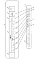
- FIG. 4 is an explanatory diagram of the correspondence information 40 and the IPv6 address 50 according to the first embodiment.
- the correspondence information 40 includes an ID 41, a country ID 421, a prefecture ID 422, a municipality ID 423, a region ID 424, a building ID 425, a floor ID 426, a device ID 43, and a MAC address 44.
- ID 41 is a sequential record number in the table in which the correspondence information 40 is stored.
- the country ID 421, the prefecture ID 422, the municipality ID 423, the region ID 424, the building ID 425, and the floor ID 426 are position information 42 indicating the installation position of the communication device 30.
- the device ID 43 is an identifier of the communication device 30 at the installation position indicated by the position information 42.
- the MAC address 44 is the MAC address of the communication device 30.
- ID 41, country ID 421, prefecture ID 422, municipality ID 423, region ID 424, building ID 425, and floor ID 426 are Integer type data.
- the device ID 43 is Integrer type data.
- the MAC address 44 is CHAR type data.
- the correspondence information acquisition unit 22 acquires the correspondence information 40 required by the address management device 20 from the database storing all the correspondence information 40 in the network system 10 and stores it in the correspondence information storage unit 21.
- the facility management computer 16 includes the database.
- the correspondence information acquisition unit 22 can acquire the correspondence information 40 required by the address management device 20 by searching the database using the installation position of the address management device 20 as a search keyword. At this time, the correspondence information acquisition unit 22 searches the database with the granularity of the management range of the address management device 20. For example, when the address management device 20 manages a plurality of floors of a building, the country ID 421 to the building ID 425 are connected with an AND condition and searched as a search keyword. On the other hand, when the address management device 20 manages a floor with a building, the country ID 421 to the floor ID 426 are connected with an AND condition and searched as a search keyword.
- the receiving unit 23 receives the router request message RS from the communication device 30.
- the router solicitation message RS is a message defined by plug and play in IPv6.
- the router request message RS includes the MAC address of the communication device 30.
- the information acquisition unit 24 acquires the position information 42 and the device ID 43 corresponding to the MAC address included in the router request message RS received by the reception unit 23 from the correspondence information 40 stored in the correspondence information storage unit 21.
- the address generation unit 25 generates the IPv6 address 50 using the position information 42 and the device ID 43 acquired by the information acquisition unit 24. As illustrated in FIG. 4, the address generation unit 25 converts the position information 42 into a numerical value according to the conversion rule to generate a position bit string 51, and converts the device ID 43 into a numerical value according to the conversion rule to generate a device bit string 52. Then, the address generation unit 25 generates an IPv6 address 50 including the position bit string 51 and the device bit string 52. Specifically, the address generation unit 25 generates an IPv6 address 50 in which the provider address 60 assigned to the building management company is the upper 64 bits, and the position bit string 51 and the device bit string 52 are the lower 64 bits.
- the position information 42 is information that hierarchically indicates positions from a wide range to a narrow range.
- positions from the country ID 421 to the floor ID 426 are shown hierarchically.
- the position bit string 51 includes a hierarchy bit string 53 obtained by converting the position indicated by each hierarchy of the position information 42. That is, the position bit string 51 includes a hierarchical bit string 53 obtained by converting each ID from the country ID 421 to the floor ID 426.
- each hierarchical bit string 53 is 1 byte
- the device bit string 52 is 2 bytes.
- the sizes of the hierarchical bit string 53 and the equipment bit string 52 are determined according to the system.
- the transmission unit 26 transmits the IPv6 address 50 generated by the address generation unit 25 on the router advertisement message RA to the communication device 30 that is the transmission source of the router solicitation message RS.
- the router advertisement message RA is a message defined by plug and play in IPv6.
- FIG. 5 is a flowchart showing the operation of the network system 10 according to the first embodiment.
- FIG. 5 shows an operation when the communication device 30 is newly connected to the second layer network managed by the address management device 20.
- correspondence information 40 necessary for the address management device 20 is stored in the correspondence information storage unit 21. Note that there is no difference in operation regardless of the configuration shown in FIGS.
- the operation of the network system 10 according to the first embodiment corresponds to the address management method according to the first embodiment.
- the operation of the network system 10 according to the first embodiment corresponds to the processing procedure of the address management program according to the first embodiment.
- the communication device 30 newly connected to the second layer network transmits a router solicitation message RS including its own MAC address.
- the communication device 30 generates a link local address using the MAC address, and multicasts the router solicitation message RS using the generated link local address.
- the receiving unit 23 receives the router solicitation message RS transmitted in S1.
- the information acquisition unit 24 uses the location information 42 and the device ID 43 corresponding to the MAC address included in the router request message RS received in S2 from the correspondence information 40 stored in the correspondence information storage unit 21. To get.
- the address generation unit 25 In the address generation process of S4, the address generation unit 25 generates the IPv6 address 50 using the position information 42 and the device ID 43 acquired in S3.
- the transmission unit 26 carries the IPv6 address 50 generated in S4 on the router advertisement message RA and transmits it to the communication device 30 that is the transmission source of the router solicitation message RS.
- the communication device 30 newly connected to the second layer network receives the router advertisement message RA transmitted in S5. As a result, the communication device 30 acquires an IPv6 address.
- S2 to S5 are collectively referred to as an address management process.
- the address management device 20 is provided for each range that can be multicast. Therefore, any address management device 20 can receive the router solicitation message RS multicast from the newly connected communication device 30. Therefore, the IPv6 address 50 can be automatically set for the communication device 30 even in the existing network configuration.
- the IPv6 address 50 is generated from the position information 42 corresponding to the MAC address of the communication device 30. Therefore, the installation position of the communication device 30 and the IPv6 address 50 can be managed collectively, and the management of the communication device 30 can be simplified.
- the communication device 30 that has acquired the IPv6 address communicates with another communication device 30 in the second layer network
- the communication device 30 that has acquired the IPv6 address sends a neighbor search message to the other communication device 30. Transmit and receive a neighbor advertisement message from another communication device 30.
- the MAC address is resolved, and it becomes possible to communicate with other communication devices 30 in the second layer network.
- the router solicitation message RS and the router advertisement message RA in IPv6 are used.
- messages having different names may be used as long as the messages have the same role as the router solicitation message RS and the router advertisement message RA.
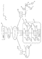
- Embodiment 2 a case in which there is a sub communication device 31 connected to the IPv6 network 11 via the communication device 30 will be described. In the second embodiment, a description will be given focusing on differences from the first embodiment.
- a wireless communication path is installed.
- the communication device 30 is installed as a gateway to the wireless network.
- the sub communication device 31 is connected to the IPv6 network 11 using the communication device 30 as a gateway.
- wireless LANs defined by IEEE 802.11, Bluetooth (registered trademark) and Zigbee (registered trademark) defined by IEEE 802.15, etc.
- STD-T108 There are various types of wireless systems, but mainly used in buildings are wireless LANs defined by IEEE 802.11, Bluetooth (registered trademark) and Zigbee (registered trademark) defined by IEEE 802.15, etc. And STD-T108. Each radio system has a carrier frequency, a modulation scheme, a channel model, access control, and the like.
- FIG. 6 is an overall configuration diagram of the network system 10 according to the second embodiment.
- the network system 10 shown in FIG. 6 is different from the network system 10 shown in FIG. 1 in that it includes a sub communication device 31 connected to the IPv6 network 11 via the communication device 30.
- FIG. 7 is an explanatory diagram of the correspondence information 40 and the IPv6 address 50 according to the second embodiment.
- the correspondence information 40 shown in FIG. 7 is different from the correspondence information 40 shown in FIG. That is, the correspondence information 40 illustrated in FIG. 7 associates the position information 42, the device ID 43, and the sub device ID 45, which is the identifier of the sub communication device 31 in the communication device 30 indicated by the device ID 43, for each MAC address 44. Information.
- the address generation unit 25 of the address management device 20 sets an IPv6 address 50 in which the provider address 60 assigned to the building management company is set to the upper 64 bits, and the position bit string 51, the device bit string 52, and the sub equipment bit string 54 are set to the lower 64 bits. Generate. At this time, the address generation unit 25 sets a predetermined value for the communication device 30 for the bit corresponding to the sub device ID 45.
- each hierarchical bit string 53, device bit string 52, and sub device bit string 54 are 1 byte. Note that the sizes of the hierarchical bit string 53 and the device bit string 52 and the sub device bit string 54 are determined according to the system.
- the communication device 30 generates an IPv6 address 55 for the sub communication device 31 when the sub communication device 31 having itself as a gateway is connected.
- the communication device 30 is a sub device bit string 54 obtained by converting the sub device ID 45 that is an identifier of the sub communication device 31 into a numerical value according to the conversion rule, and a bit string assigned to the sub device ID 45 in the IPv6 address 50 transmitted by the address management device 20. Instead, an IPv6 address 55 for the sub communication device 31 is generated. Then, the communication device 30 transmits the generated IPv6 address 55 to the sub communication device 31.
- the sub device ID 45 is determined by the communication device 30 so as to be unique for each communication device 30 when the sub communication device 31 is connected.
- the communication device 30 changes part of its own IPv6 address 50 to the IPv6 address 55 with respect to the sub communication device 31 having the communication device 30 as a gateway. Is generated. Thereby, the IPv6 address 55 can be automatically set for the sub communication device 31.
- the facility management computer 16 can directly communicate with the sub communication device 31 using the IPv6 address 55.
- the sub communication device 31 is in a sleep state for a certain period so that it can be used for a long time by battery drive. For this reason, when the sub-communication device 31 is accessed from the facility management computer 16 or the like, the IPv6 address valid period may expire. Therefore, delay time arbitration and state management in such a case are implemented in the communication device 30 as a gateway function of the communication device 30.
- the communication device 30 functions as a gateway to the wireless network.
- the communication device 30 may function as a gateway for non-procedural serial communication such as RS-485 instead of a wireless network.
- the IPv6 address 55 can be automatically set for the sub communication device 31 in the same manner.
- FIG. 8 is a diagram illustrating a hardware configuration example of the address management device 20, the communication device 30, and the sub communication device 31 according to the first and second embodiments.
- the address management device 20, the communication device 30, and the sub communication device 31 are computers.
- the address management device 20, the communication device 30, and the sub communication device 31 include hardware such as a processor 901, an auxiliary storage device 902, a memory 903, a communication device 904, an input interface 905, and a display interface 906.
- the processor 901 is connected to other hardware via the signal line 910, and controls these other hardware.
- the input interface 905 is connected to the input device 907 by a cable 911.
- the display interface 906 is connected to the display 908 by a cable 912.
- the processor 901 is an IC (Integrated Circuit) that performs processing.
- the processor 901 is, for example, a CPU (Central Processing Unit), a DSP (Digital Signal Processor), or a GPU (Graphics Processing Unit).
- the auxiliary storage device 902 is, for example, a ROM (Read Only Memory), a flash memory, or an HDD (Hard Disk Drive).
- the memory 903 is, for example, a RAM (Random Access Memory).
- the communication device 904 includes a receiver 9041 that receives data and a transmitter 9042 that transmits data.
- the communication device 904 is, for example, a communication chip or a NIC (Network Interface Card).
- the input interface 905 is a port to which the cable 911 of the input device 907 is connected.
- the input interface 905 is, for example, a USB (Universal Serial Bus) terminal.
- the display interface 906 is a port to which the cable 912 of the display 908 is connected.
- the display interface 906 is, for example, a USB terminal or an HDMI (registered trademark) (High Definition Multimedia Interface) terminal.
- the input device 907 is, for example, a mouse, a keyboard, or a touch panel.
- the display 908 is, for example, an LCD (Liquid Crystal Display).
- the auxiliary storage device 902 includes the above-described correspondence information acquisition unit 22, reception unit 23, information acquisition unit 24, address generation unit 25, transmission unit 26, router function unit 27 (hereinafter, correspondence information acquisition unit 22, reception unit 23, The information acquisition unit 24, the address generation unit 25, the transmission unit 26, and the router function unit 27 are collectively stored as a program that realizes the function of “unit”. This program is loaded into the memory 903, read into the processor 901, and executed by the processor 901. Further, the auxiliary storage device 902 also stores an OS (Operating System). Then, at least a part of the OS is loaded into the memory 903, and the processor 901 executes a program that realizes the function of “unit” while executing the OS. Although one processor 901 is illustrated in FIG.
- the address management device 20, the communication device 30, and the sub communication device 31 may include a plurality of processors 901.
- a plurality of processors 901 may execute a program for realizing the function of “unit” in cooperation with each other.
- information, data, signal values, and variable values indicating the processing results of “part” and information, data, signal values, and variable values stored in the correspondence information storage unit 21 are stored in the memory 903, the auxiliary storage device 902, Alternatively, it is stored as a file in a register or cache memory in the processor 901.
- Parts may be provided by “Circuitry”. Further, “part” may be read as “circuit”, “process”, “procedure”, or “processing”. “Circuit” and “Circuitry” include not only the processor 901 but also other types of processing circuits such as logic IC, GA (Gate Array), ASIC (Application Specific Integrated Circuit), or FPGA (Field-Programmable Gate Array). It is a concept to include.
Landscapes
- Engineering & Computer Science (AREA)
- Computer Networks & Wireless Communication (AREA)
- Signal Processing (AREA)
- Small-Scale Networks (AREA)
- Data Exchanges In Wide-Area Networks (AREA)
Priority Applications (3)
| Application Number | Priority Date | Filing Date | Title |
|---|---|---|---|
| PCT/JP2015/052435 WO2016121043A1 (ja) | 2015-01-29 | 2015-01-29 | ネットワークシステム、アドレス管理装置及びアドレス管理方法 |
| JP2016571587A JP6194128B2 (ja) | 2015-01-29 | 2015-01-29 | ネットワークシステム、アドレス管理装置及びアドレス管理方法 |
| CN201580071303.5A CN107113207B (zh) | 2015-01-29 | 2015-01-29 | 网络系统、地址管理装置以及地址管理方法 |
Applications Claiming Priority (1)
| Application Number | Priority Date | Filing Date | Title |
|---|---|---|---|
| PCT/JP2015/052435 WO2016121043A1 (ja) | 2015-01-29 | 2015-01-29 | ネットワークシステム、アドレス管理装置及びアドレス管理方法 |
Publications (1)
| Publication Number | Publication Date |
|---|---|
| WO2016121043A1 true WO2016121043A1 (ja) | 2016-08-04 |
Family
ID=56542695
Family Applications (1)
| Application Number | Title | Priority Date | Filing Date |
|---|---|---|---|
| PCT/JP2015/052435 WO2016121043A1 (ja) | 2015-01-29 | 2015-01-29 | ネットワークシステム、アドレス管理装置及びアドレス管理方法 |
Country Status (3)
| Country | Link |
|---|---|
| JP (1) | JP6194128B2 (zh) |
| CN (1) | CN107113207B (zh) |
| WO (1) | WO2016121043A1 (zh) |
Cited By (1)
| Publication number | Priority date | Publication date | Assignee | Title |
|---|---|---|---|---|
| CN112291378A (zh) * | 2019-07-25 | 2021-01-29 | 阿自倍尔株式会社 | 地址管理装置及地址管理方法 |
Families Citing this family (3)
| Publication number | Priority date | Publication date | Assignee | Title |
|---|---|---|---|---|
| JP7038915B2 (ja) * | 2019-07-05 | 2022-03-18 | 三菱電機株式会社 | 中継装置およびネットワークシステム |
| CN111614793B (zh) * | 2020-04-22 | 2022-03-04 | 上海御渡半导体科技有限公司 | 一种基于fpga的以太网交换机的mac地址管理装置及方法 |
| CN114095420B (zh) * | 2022-01-20 | 2022-05-31 | 苏州浪潮智能科技有限公司 | 链路聚合方法、装置、电子设备及存储介质 |
Citations (3)
| Publication number | Priority date | Publication date | Assignee | Title |
|---|---|---|---|---|
| JP2005204286A (ja) * | 2003-12-18 | 2005-07-28 | Kddi Corp | 位置情報に基づくipアドレス決定方法及びその受信パケット判定方法、並びに装置及びプログラム |
| JP2007251477A (ja) * | 2006-03-15 | 2007-09-27 | Nec Corp | 情報同報システム、情報同報方法並びにそのプログラム |
| JP2014165761A (ja) * | 2013-02-26 | 2014-09-08 | Nippon Telegr & Teleph Corp <Ntt> | ルータ装置、ユーザ端末装置、通信システム、ルータ広告メッセージ送信方法、及びアドレス情報設定方法 |
Family Cites Families (4)
| Publication number | Priority date | Publication date | Assignee | Title |
|---|---|---|---|---|
| US7929535B2 (en) * | 2006-07-07 | 2011-04-19 | Qualcomm Incorporated | Geolocation-based addressing method for IPv6 addresses |
| CN103095581B (zh) * | 2011-10-31 | 2017-03-22 | 中兴通讯股份有限公司 | 分离终端身份位置标识的系统、方法和服务路由器 |
| CN103108056B (zh) * | 2011-11-15 | 2017-05-24 | 中兴通讯股份有限公司 | 一种实现身份位置分离网络的设备及方法 |
| CN103701950B (zh) * | 2013-12-26 | 2017-09-08 | 中国联合网络通信集团有限公司 | 一种ip地址的分配方法及装置 |
-
2015
- 2015-01-29 CN CN201580071303.5A patent/CN107113207B/zh active Active
- 2015-01-29 WO PCT/JP2015/052435 patent/WO2016121043A1/ja active Application Filing
- 2015-01-29 JP JP2016571587A patent/JP6194128B2/ja active Active
Patent Citations (3)
| Publication number | Priority date | Publication date | Assignee | Title |
|---|---|---|---|---|
| JP2005204286A (ja) * | 2003-12-18 | 2005-07-28 | Kddi Corp | 位置情報に基づくipアドレス決定方法及びその受信パケット判定方法、並びに装置及びプログラム |
| JP2007251477A (ja) * | 2006-03-15 | 2007-09-27 | Nec Corp | 情報同報システム、情報同報方法並びにそのプログラム |
| JP2014165761A (ja) * | 2013-02-26 | 2014-09-08 | Nippon Telegr & Teleph Corp <Ntt> | ルータ装置、ユーザ端末装置、通信システム、ルータ広告メッセージ送信方法、及びアドレス情報設定方法 |
Cited By (1)
| Publication number | Priority date | Publication date | Assignee | Title |
|---|---|---|---|---|
| CN112291378A (zh) * | 2019-07-25 | 2021-01-29 | 阿自倍尔株式会社 | 地址管理装置及地址管理方法 |
Also Published As
| Publication number | Publication date |
|---|---|
| JP6194128B2 (ja) | 2017-09-06 |
| JPWO2016121043A1 (ja) | 2017-04-27 |
| CN107113207B (zh) | 2020-03-13 |
| CN107113207A (zh) | 2017-08-29 |
Similar Documents
| Publication | Publication Date | Title |
|---|---|---|
| JP6660348B2 (ja) | ファブリックネットワーク | |
| US7339895B2 (en) | Gateway device and control method for communication with IP and IPV6 protocols | |
| US7826462B2 (en) | Address assignment apparatus, address assignment method, and computer product | |
| JP6194128B2 (ja) | ネットワークシステム、アドレス管理装置及びアドレス管理方法 | |
| WO2018177409A1 (zh) | 一种报文传输方法及装置 | |
| JP5890076B2 (ja) | マルチインスタンス電力線通信システム | |
| CN110121864B (zh) | 不同网络通信协议之间的网络桥接的方法和设备 | |
| WO2019165775A1 (zh) | 一种局域网设备的搜索方法及搜索系统 | |
| US20070223494A1 (en) | Method for the resolution of addresses in a communication system | |
| WO2014114228A1 (en) | Item aggregation in shortest path bridging mac-in-mac mode (spbm) network | |
| US20140036917A1 (en) | Address resolution mechanism for hybrid communication networks | |
| EP4325807A2 (en) | Duplicate address detection for global ip address or range of link local ip addresses | |
| US8472420B2 (en) | Gateway device | |
| US20170332439A1 (en) | Extending the range of mesh networks | |
| WO2020038443A1 (zh) | 桥接通信的方法和设备 | |
| JP2012156957A (ja) | ネットワークシステム、制御装置、計算機、及び、ネットワーク装置 | |
| WO2015196719A1 (zh) | 一种地址配置方法、装置和设备 | |
| CN108989173B (zh) | 一种报文传输的方法及装置 | |
| CN107547691B (zh) | 地址解析协议报文代理方法和装置 | |
| JP5673133B2 (ja) | Mpls−tp装置のmac探索システム及びmac探索方法 | |
| US10862849B2 (en) | Address resolution system | |
| US20130003600A1 (en) | Configuration of Interfaces Communicatively Coupled to Link-Local Zones in a Network | |
| CN102377835B (zh) | 一种网元群组网络的通信方法和装置 | |
| KR101885618B1 (ko) | Ip기반의 디바이스 자동연결 방법 및 이를 지원하는 장치 | |
| Stolikj et al. | Nomadic service discovery in smart cities |
Legal Events
| Date | Code | Title | Description |
|---|---|---|---|
| 121 | Ep: the epo has been informed by wipo that ep was designated in this application |
Ref document number: 15879940 Country of ref document: EP Kind code of ref document: A1 |
|
| ENP | Entry into the national phase |
Ref document number: 2016571587 Country of ref document: JP Kind code of ref document: A |
|
| NENP | Non-entry into the national phase |
Ref country code: DE |
|
| 122 | Ep: pct application non-entry in european phase |
Ref document number: 15879940 Country of ref document: EP Kind code of ref document: A1 |