WO2016120992A1 - 車体構造 - Google Patents
車体構造 Download PDFInfo
- Publication number
- WO2016120992A1 WO2016120992A1 PCT/JP2015/052177 JP2015052177W WO2016120992A1 WO 2016120992 A1 WO2016120992 A1 WO 2016120992A1 JP 2015052177 W JP2015052177 W JP 2015052177W WO 2016120992 A1 WO2016120992 A1 WO 2016120992A1
- Authority
- WO
- WIPO (PCT)
- Prior art keywords
- vehicle
- frame
- vehicle body
- bolt
- subframe
- Prior art date
- Legal status (The legal status is an assumption and is not a legal conclusion. Google has not performed a legal analysis and makes no representation as to the accuracy of the status listed.)
- Ceased
Links
Images


Classifications
-
- B—PERFORMING OPERATIONS; TRANSPORTING
- B62—LAND VEHICLES FOR TRAVELLING OTHERWISE THAN ON RAILS
- B62D—MOTOR VEHICLES; TRAILERS
- B62D21/00—Understructures, i.e. chassis frame on which a vehicle body may be mounted
-
- B—PERFORMING OPERATIONS; TRANSPORTING
- B62—LAND VEHICLES FOR TRAVELLING OTHERWISE THAN ON RAILS
- B62D—MOTOR VEHICLES; TRAILERS
- B62D25/00—Superstructure or monocoque structure sub-units; Parts or details thereof not otherwise provided for
- B62D25/20—Floors or bottom sub-units
Definitions
- the present invention relates to a vehicle body structure including a front subframe.
- the front subframe that supports vehicle suspension parts and the like is attached to the lower part of the body frame such as a side member that extends in the longitudinal direction of the body.
- the front sub-frame that receives an impact load from the front of the vehicle has a rear portion that abuts against a reinforcing member provided on the vehicle body, and a central portion is bent in a V shape below the vehicle. Leave.
- the front subframe does not bend and does not leave the vehicle body.
- an object of the present invention is to enable the front subframe to be easily detached from the vehicle body when receiving an impact load from the front of the vehicle.
- a reinforcing member having an inclined portion that is inclined at a lower portion of the lower inclined portion of the dash panel so that a lower portion in the vehicle vertical direction is on the vehicle rear side from the upper portion is provided.
- a fixing member for fixing the vehicle rear end portion of the front sub-frame is provided on the attachment member provided on the inclined portion of the reinforcing member.
- an upper portion protruding upward from the front subframe is disposed close to the inclined portion of the reinforcing member.
- the upper portion of the fixture comes into contact with the inclined portion of the reinforcing member and moves downward along with the front subframe along the inclined portion.
- the vehicle rear portion of the front sub-frame is detached from the reinforcing member and easily detached from the vehicle body.
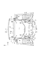
- FIG. 1 is a cross-sectional view taken along the line AA of FIG. 2, showing a vehicle body structure according to an embodiment of the present invention.
- FIG. 2 is a bottom view of the front portion of the vehicle body having the vehicle body structure of FIG. 1 as viewed from below.
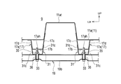
- 3 is a cross-sectional view taken along the line BB of FIG.
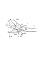
- FIG. 4 is an enlarged cross-sectional view of a main part of FIG.
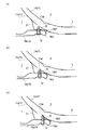
- FIG. 5 is an operation explanatory diagram when a vehicle having the vehicle body structure of FIG. 1 receives an impact from the front.
- FIG. 6 is a cross-sectional view corresponding to FIG. 4 showing another embodiment of the present invention.
- FIG. 1 and 2 show a vehicle body structure of a vehicle front portion according to an embodiment of the present invention.
- the arrow FR indicates the front of the vehicle body
- the arrow LH indicates the left side of the vehicle body
- the arrow UP indicates the upper side of the vehicle body.
- a pair of left and right side members 1 extend in the vehicle longitudinal direction on both sides in the vehicle width direction.
- Bumper reinforcements 5 extending in the vehicle width direction are coupled to the front end portions of the left and right side members 1 via bumper stays 3.
- the bumper stay 3 and the bumper reinforcement 5 are omitted.
- the side member 1 is provided with a side member front portion 1a located substantially in the center of the vehicle body in the vertical direction within the engine compartment 7 at the front portion of the vehicle body.
- the side member 1 on the side of the vehicle compartment 9 behind the engine compartment 7 includes a side member rear portion 1b (see FIG. 2) that is bent downward from the rear end of the side member front portion 1a and positioned at the lower portion of the vehicle body.
- the engine compartment 7 and the vehicle compartment 9 are partitioned by a dash panel 11.
- the dash panel 11 includes a curved portion 11 a as a lower inclined portion that bends so that the lower portion is curved toward the rear, and the rear end of the curved portion 11 a is at the front end of the floor panel 13.
- a floor tunnel 15 shown in FIG. 2 is provided at the center of the floor panel 13 in the vehicle width direction.
- the floor tunnel 15 extends in the vehicle front-rear direction with the floor panel 13 projecting toward the vehicle compartment 9 side.
- the front end portion of the floor tunnel 15 is joined to a tunnel portion 11at protruding toward the vehicle compartment 9 side of the curved portion 11a shown in FIG. 3 which is a BB cross-sectional view of FIG.
- a tunnel member 17 serving as a reinforcing member for reinforcing the tunnel portion 11at and the floor tunnel 15 is provided on the lower surfaces of both sides in the vehicle width direction from the tunnel portion 11at to the vicinity of the front end portion of the floor tunnel 15.
- the tunnel member 17 forms a closed cross section between the tunnel portion 11 at and the floor tunnel 15 at the lower part of both ends in the vehicle width direction of the tunnel portion 11 at and the floor tunnel 15. That is, the tunnel member 17 includes a bottom surface 17b and left and right side surfaces 17c and 17d that rise upward from both ends of the bottom surface 17b in the vehicle width direction. The upper ends of the side surfaces 17c and 17d are bonded and fixed to the tunnel portion 11at and the floor tunnel 15.
- the tunnel member 17 includes a tunnel member curved portion 17 a corresponding to the curved portion 11 a of the dash panel 11.
- the tunnel member bending portion 17a forms an inclined portion that is inclined such that the lower portion in the vehicle vertical direction is on the vehicle rear side with respect to the upper portion.
- the front subframe 19 is located below the side member front 1a.
- the front sub-frame 19 connects a front part 19a extending in the vehicle width direction at the front part of the vehicle body, a rear part 19b located at the rear part of the vehicle body, and the front part 19a and the rear part 19b at both ends in the vehicle width direction. And a pair of left and right side portions 19c.
- the side part 19c is extended in the vehicle body front-back direction.
- the upper region of the front subframe 19 is the engine compartment 7.
- the front portion 19a supports a cooling system component and the like (not shown).
- the cooling system components supported by the front portion 19a are also supported by a pair of left and right side members 21 whose lower portions are coupled to the front end portion of the side member front portion 1a and an upper member 23 that couples the pair of left and right side members 21 to each other. .
- the rear portion 19b supports undercarriage parts and operation system parts (not shown). As shown in FIG. 2, the rear portion 19b is long in the vehicle width direction and the vehicle body front-rear direction and is formed in a substantially rectangular shape as a whole. Projection portions 19b1 projecting obliquely forward on the vehicle width direction outer side are formed at the vehicle body front end portions at both ends in the vehicle width direction of the rear portion 19b, and the projection portions 19b1 are connected to the rear ends of the side portions 19c.
- the upper ends of the front connecting members 25 extending in the vertical direction are connected to the front end portions of the left and right side member front portions 1a, respectively.
- the lower ends of the left and right front connection members 25 are connected to the vehicle width direction end portions of the front portion 19a of the front subframe 19, respectively. That is, the front portion 19a of the front subframe 19 is supported by the side member front portion 1a by the front connecting member 25 at the support point P shown in FIG.
- the upper ends of the central connecting members 27 extending in the vertical direction are connected to the rear ends of the left and right side member front portions 1a, respectively.
- the lower ends of the left and right central connecting members 27 are connected to the vicinity of the protruding portion 19b1 of the rear portion 19b of the front subframe 19, respectively. That is, the front portion of the rear portion 19b of the front subframe 19 is supported by the side member front portion 1a by the central connecting member 27 at the support point Q shown in FIG.
- the substantially center in the vehicle front-rear direction of the rear portion 19b of the front subframe 19 connects the inner end portions of the rear connecting member 29 on both sides in the vehicle width direction.
- the outer ends in the vehicle width direction of the rear connecting members 29 are connected to the left and right side member rear portions 1b, respectively. That is, the center in the vehicle longitudinal direction of the rear portion 19b of the front subframe 19 is supported by the side member rear portion 1b by the rear connecting member 29 at the support point R shown in FIG.
- the rear end portion 19b2 of the rear portion 19b of the front subframe 19 is connected to the tunnel member 17 via a bracket 31 as a mounting member and a bolt 33 as a fixture. That is, the rear end portion 19b2 of the rear portion 19b of the front subframe 19 is supported by the tunnel member 17 by the bracket 31 and the bolt 33 at the support point S shown in FIG.
- the bracket 31 is welded and fixed to the lower surface of the tunnel member curved portion 17a. As shown in an enlarged view in FIG. 4, the bracket 31 includes a bottom surface portion 31 a and a vertical surface portion 31 b that is bent upward from the front end of the bottom surface portion 31 a and extends in the vertical direction. The flanges 31af and 31bf at the end portions of the bottom surface portion 31a and the vertical surface portion 31b are joined and fixed to the lower surface of the tunnel member bending portion 17a.
- the bracket 31 further has substantially triangular side portions 31c on both sides in the vehicle width direction. As shown in FIG. 3, the upper end of the side surface portion 31c is welded and fixed to the lower portions of the side surfaces 17c and 17d of the tunnel member curved portion 17a.
- the rear end portion 19b2 of the rear portion 19b of the front subframe 19 is fastened and fixed by using a bolt 33 and a nut 35 with a flat upper surface 19b3 abutting against the bottom surface portion 31a of the bracket 31.
- the bolt 33 is inserted into a bolt insertion hole penetrating in the vertical direction of the front subframe 19 from the lower side to the upper side, and is fastened to a nut 35 that is welded and fixed onto the bottom surface portion 31 a of the bracket 31.
- a spacer 36 made of a cylindrical collar or anti-vibration rubber is disposed in the front subframe 19 at a portion having a bolt insertion hole, and the bolt 33 is inserted into the spacer 36.
- the tip (upper end) of the bolt 33 is inserted into a through hole 17ah as a recess formed in the lower surface of the tunnel member curved portion 17a.
- the tip (upper end) of the bolt 33 slightly protrudes from the through-hole 17ah into the inner space 37 of the upper tunnel member curved portion 17a, and on the vehicle front side of the edge of the through-hole 17ah on the vehicle rear side, The tip is located. That is, the front end portion of the bolt 33 is located at a position close to the front side of the vehicle with respect to the edge of the through hole 17ah on the rear side of the vehicle.
- the inner space 37 of the tunnel member bending portion 17a has a front space 37a and a rear space 37b with the bolt 33 as a boundary in a side view shown in FIG.
- the rear end portion 19b2 of the rear portion 19b of the front subframe 19 has an inclined surface 19b4 whose upper corner faces the tunnel member curved portion 17a and is inclined along the tunnel member curved portion 17a.
- the inclined surface 19b4 is separated from the tunnel member curved portion 17a.
- the upper portion of the bolt 33 is pressed against the edge of the through-hole 17ah, so that the upper portion is bent as shown in FIG. 5C, or the lower portion is inclined so as to be behind the vehicle rather than the upper portion. , Comes out of the through hole 17ah.
- the bolt 33 that has come out of the through hole 17ah moves to the lower rear side along the lower surface of the tunnel member curved portion 17a.
- the inclined surface 19b4 of the rear end portion 19b2 of the front subframe 19 moves rearward and downward along the tunnel member curved portion 17a while contacting the lower surface of the tunnel member curved portion 17a.
- the contact of the inclined surface 19b4 of the front subframe 19 with the tunnel member curved portion 17a is after the front end side portion of the bolt 33 contacts the edge portion of the through hole 17ah.
- the bolt 33 moves to the lower rear together with the front sub-frame 19 so that the tip is pushed down while contacting the lower surface of the tunnel member curved portion 17a. Since the upper end of the bolt 33 and the inclined surface 19b4 of the front subframe 19 move along the lower surface of the tunnel member curved portion 17a, the movement of the front subframe 19 to the lower rear is further ensured.
- the bracket 31 is also deformed as described above. Due to the deformation of the bracket 31, the fastening state of the front subframe 19 to the bracket 31 by the bolt 33 and the nut 35 is released, and the rear end portion 19b2 of the front subframe 19 is detached from the tunnel member 17 and detached from the vehicle body.
- the rear end portion 19b2 of the front sub frame 19 is detached from the vehicle body, so that the movement of the front sub frame 19 toward the compartment 9 can be suppressed.
- the upper portion of the bolt 33 contacts the tunnel member curved portion 17a, and the front subframe 19 extends along the tunnel member curved portion 17a. And move downward.
- the front subframe 19 has the rear end 19b2. It is detached from the tunnel member 17 and easily detached from the vehicle body.
- the through hole 17ah is formed in the tunnel member curved portion 17a, and the upper portion of the bolt 33 enters the through hole 17ah. For this reason, when the front sub-frame 19 moves backward, the bolt 33 moves more reliably downward while being guided by the through hole 17ah while contacting the edge of the through hole 17ah.
- the upper corner portion of the rear end portion 19b2 of the front sub-frame 19 facing the tunnel member curved portion 17a includes an inclined surface 19b4 that is inclined along the tunnel member curved portion 17a.
- FIG. 6 shows another embodiment of the present invention.
- the bolt 33 ⁇ / b> A is inserted into the bolt insertion hole from above the front subframe 19 downward.
- the tip of the threaded portion of the bolt 33A protrudes below the front subframe 19, and a nut 35A is fastened to the protruding threaded portion.
- the bolt 33 ⁇ / b> A has the head 33 ⁇ / b> Aa fixed to the bottom surface 31 a of the bracket 31 by welding.
- the head 33Aa of the bolt 33A is provided with a protrusion 33Ab at the top, and the protrusion 33Ab is inserted into the through hole 17ah of the tunnel member bending portion 17a, like the tip of the bolt 33 in FIG.
- the protrusion 33Ab of the head 33Aa of the bolt 33A replaces the tip (upper end) of the bolt 33 of FIG. That is, when the vehicle receives an impact from the front and the front subframe 19 moves backward, the protrusion 33Ab moves downward while contacting the edge of the through hole 17ah on the vehicle rear side, and then the lower surface of the tunnel member curved portion 17a. Move down along the bottom.
- the front end side portion of the bolt 33 or the front end side portion of the projection 33Ab of the bolt 33A is separated from the edge of the through hole 17ah on the vehicle rear side. It may be.
- the tip of the bolt 33 or the protrusion 33Ab of the bolt 33A is inserted into the through hole 17ah, but without the through hole 17ah,
- the tip or the protrusion 33Ab of the bolt 33A may be in the state of being close to or in contact with the lower surface of the tunnel member bending portion 17a.
- the bracket 31 for attaching the front subframe 19 to the vehicle body is not limited to the configuration for attaching to the tunnel member 17 that is a reinforcing member.
- the bracket 31 may be attached to the lower surface of the curved portion 11a of the dash panel 11 at a position shifted in the vehicle width direction with respect to the tunnel member 17 via a reinforcing member having an inclined portion.
- the vicinity of the center in the vehicle front-rear direction may be bent in an inverted V shape upward or in a V shape downward. It is done.
- the rear portion 19b of the front subframe 19 is inclined so that the front is higher than the rear.
- the bolt 33 is inclined so that the upper part is located behind the vehicle rather than the lower part, the upper part of the bolt 33 comes into contact with the edge of the through-hole 17ah or the lower surface of the tunnel member curved part 17a at an early stage.
- the rear end portion 19b2 of the front subframe 19 can be moved to the lower rear side earlier.
- the rear portion 19b of the front sub-frame 19 is inclined so that the rear is higher than the front.
- the rear portion 19b of the front sub-frame 19 is inclined so that the rear side of the vehicle is above the front side, so that the inclined surface 19b4 of the rear end portion 19b2 of the front sub-frame 19 is more early than the lower surface of the tunnel member curved portion 17a.
- the rear end portion 19b2 of the front subframe 19 can be moved to the lower rear side earlier.
- the present invention is applied to a vehicle body structure including a front subframe.
Landscapes
- Engineering & Computer Science (AREA)
- Chemical & Material Sciences (AREA)
- Combustion & Propulsion (AREA)
- Transportation (AREA)
- Mechanical Engineering (AREA)
- Body Structure For Vehicles (AREA)
Abstract
ダッシュパネル(11)の下部傾斜部(11a)の下面に、車両前後方向に延設される補強部材(17)が結合される。補強部材(17)の傾斜部(17a)の下面に固定される取付部材(31)に、フロントサブフレーム(19)の車両後端部(19b2)を固定具(33)により締結固定する。車両が前方から衝撃を受けてフロントサブフレーム(19)が後退すると、固定具(33)の上端が傾斜部(17a)に沿って下方に押下げられて、フロントサブフレーム(19)の車両後端部(19b2)が車体から離脱する。
Description
本発明は、フロントサブフレームを備える車体構造に関する。
車両のサスペンション部品などを支持するフロントサブフレームは、車体前後方向に延設されるサイドメンバなどの車体フレームの下部に取り付けられる。特許文献1の車体構造は、車両前方から衝撃荷重を受けたフロントサブフレームが、車体に設けた補強部材に後部が当接して中央部が車両下方にV字状に屈曲し、最終的に車体から離脱する。
しかし、上記従来の車体構造は、車両前部に配置されるエンジンの車両前後方向長さが長いなどの要因で、クラッシュストロークを充分確保できない場合に、フロントサブフレームが屈曲せず車体から離脱しないことがある。
そこで、本発明は、フロントサブフレームが、車両前方から衝撃荷重を受けたときに、車体から容易に離脱できるようにすることを目的としている。
本発明は、ダッシュパネルの下部傾斜部の下部に、車両上下方向の下部が上部よりも車両後方側となるよう傾斜する傾斜部を有する補強部材が設けられる。補強部材の傾斜部に設けられた取付部材に、フロントサブフレームの車両後端部を固定する固定具を備える。固定具は、フロントサブフレームから上方に突出する上部が補強部材の傾斜部に近接配置されている。
本発明によれば、フロントサブフレームが車両前方から衝撃荷重を受けたときに、固定具の上部が補強部材の傾斜部に接触し傾斜部に沿ってフロントサブフレームと共に下方に移動する。これにより、フロントサブフレームの車両後部が補強部材から外れて車体から容易に離脱する。
以下、本発明を実施するための形態について、図面を参照して詳細に説明する。
図1及び図2は、本発明の一実施形態に係わる車両前部の車体構造を示す。図中で矢印FRは車体前方、矢印LHは車体左方、矢印UPは車体上方、をそれぞれ示す。
車体下方から見た図2に示すように、車幅方向両側には車体前後方向に向けて左右一対のサイドメンバ1を延設している。左右のサイドメンバ1の前端部には、バンパステイ3を介して、車幅方向に延設されるバンパレインフォース5を結合している。図1では、バンパステイ3とバンパレインフォース5は省略している。
図1に示すように、サイドメンバ1は、車体前部のエンジンコンパートメント7内で車体上下方向のほぼ中央に位置するサイドメンバ前部1aを備える。エンジンコンパートメント7の後方の車室9側のサイドメンバ1は、サイドメンバ前部1aの後端から下方に屈曲して車体下部に位置するサイドメンバ後部1b(図2参照)を備える。エンジンコンパートメント7と車室9とは、ダッシュパネル11により仕切られている。
図1に示すように、ダッシュパネル11は、下部が後方に向けて湾曲するようにして屈曲する下部傾斜部としての湾曲部11aを備え、湾曲部11aの後端はフロアパネル13の前端部に連結される。フロアパネル13の車幅方向中央には、図2に示すフロアトンネル15が設けられている。フロアトンネル15は、フロアパネル13に対し車室9側に突出した状態で車両前後方向に延設される。フロアトンネル15の前端部は、図1のB-B断面図である図3に示す湾曲部11aの車室9側に突出するトンネル部11atに接合される。
トンネル部11atからフロアトンネル15の前端部付近にわたり、これらの車幅方向両側の下面には、トンネル部11at及びフロアトンネル15を補強する補強部材となるトンネルメンバ17を設けている。トンネルメンバ17は、図3に示すようにトンネル部11at及びフロアトンネル15の車幅方向両端部の下部にて、トンネル部11at及びフロアトンネル15との間で閉断面を形成する。すなわち、トンネルメンバ17は、底面17b及び、底面17bの車幅方向両端から上方に向けて立ち上がる左右の側面17c,17dを備える。側面17c,17dの上端がトンネル部11at及びフロアトンネル15に接合固定される。
トンネルメンバ17は、ダッシュパネル11の湾曲部11aに対応するトンネルメンバ湾曲部17aを備えている。トンネルメンバ湾曲部17aは、車両上下方向の下部が上部よりも車両後方側となるよう傾斜する傾斜部を構成している。
サイドメンバ前部1aの下方にフロントサブフレーム19が位置している。フロントサブフレーム19は、車体前部にて車幅方向に延設されるフロント部19aと、車体後部に位置するリア部19bと、フロント部19aとリア部19bとを車幅方向両端でそれぞれ連結する左右一対のサイド部19cと、を備える。サイド部19cは車体前後方向に延設される。フロントサブフレーム19の上方領域がエンジンコンパートメント7となる。
フロント部19aは、図示しない冷却系部品などを支持する。フロント部19aが支持する冷却系部品は、サイドメンバ前部1aの前端部に下部が結合する左右一対のサイド部材21及び、左右一対のサイド部材21相互を連結する上部部材23にも支持される。
リア部19bは、図示しない足回り部品及び操作系部品を支持する。リア部19bは、図2に示すように、車幅方向及び車体前後方向に長く全体としてほぼ矩形状に形成されている。リア部19bの車幅方向両端の車体前端部には、車幅方向外側の斜め前方に突出する突出部19b1が形成され、突出部19b1をサイド部19cの後端に連結している。
次に、フロントサブフレーム19の車体側への取付構造について説明する。
左右のサイドメンバ前部1aの各前端部に、上下方向に延設される前部連結部材25の上端をそれぞれ連結する。左右の各前部連結部材25の下端は、フロントサブフレーム19のフロント部19aの車幅方向端部にそれぞれ連結する。すなわち、フロントサブフレーム19のフロント部19aは、図2に示す支持点Pにおいて前部連結部材25によりサイドメンバ前部1aに支持される。
左右のサイドメンバ前部1aの各後端部に、上下方向に延設される中央連結部材27の上端をそれぞれ連結する。左右の各中央連結部材27の下端は、フロントサブフレーム19のリア部19bの突出部19b1付近にそれぞれ連結する。すなわち、フロントサブフレーム19のリア部19bの前部は、図2に示す支持点Qにおいて中央連結部材27によりサイドメンバ前部1aに支持される。
フロントサブフレーム19のリア部19bの車両前後方向ほぼ中央は、車幅方向両側にて後部連結部材29の内側端部をそれぞれ連結する。各後部連結部材29の車幅方向外側端部は、左右のサイドメンバ後部1bにそれぞれ連結する。すなわち、フロントサブフレーム19のリア部19bの車両前後方向中央は、図2に示す支持点Rにおいて後部連結部材29によりサイドメンバ後部1bに支持される。
図1に示すように、フロントサブフレーム19のリア部19bの後端部19b2は、取付部材としてのブラケット31及び、固定具としてのボルト33を介してトンネルメンバ17に連結している。すなわち、フロントサブフレーム19のリア部19bの後端部19b2は、図2に示す支持点Sにおいてブラケット31及びボルト33によりトンネルメンバ17に支持されている。
ブラケット31は、トンネルメンバ湾曲部17aの下面に溶接固定されている。ブラケット31は、図4に拡大して示すように、底面部31aと、底面部31aの前端から上方に向けて屈曲して上下方向に延設される縦面部31bとを有する。底面部31aと縦面部31bの各端部のフランジ31af及び31bfを、トンネルメンバ湾曲部17aの下面に接合固定する。
ブラケット31は、さらに車幅方向両側部にほぼ三角形状の側面部31cを有する。側面部31cの上端を、図3に示すようにトンネルメンバ湾曲部17aの側面17c,17dの下部に溶接固定する。
フロントサブフレーム19のリア部19bの後端部19b2は、平坦な上面19b3をブラケット31の底面部31aに当接させて、ボルト33及びナット35を用いて締結固定する。ボルト33は、フロントサブフレーム19の上下方向に貫通するボルト挿入孔に下方から上方に向けて挿入し、ブラケット31の底面部31aの上に溶接固定しているナット35に締結する。
ボルト挿入孔を備える部分のフロントサブフレーム19内には、円筒形状のカラーもしくは防振ゴムなどからなるスペーサ36を配置し、スペーサ36内にボルト33を挿入している。ボルト33の先端(上端)は、トンネルメンバ湾曲部17aの下面に形成してある凹部としての貫通孔17ahに挿入されて入り込んでいる。
ボルト33の先端(上端)は、貫通孔17ahから上方のトンネルメンバ湾曲部17aの内部空間37に僅かに突出し、貫通孔17ahの車両後方側の縁部の車両前方側に、ボルト33の上部となる先端が位置している。つまり、ボルト33の先端側部は、貫通孔17ahの車両後方側の縁部に対し、車両前方側の近接した位置にあって離間している。
トンネルメンバ湾曲部17aの内部空間37は、図4に示す側面視で、ボルト33を境にして、前方空間37aと後方空間37bとを有する。
フロントサブフレーム19のリア部19bの後端部19b2は、上側の角部が、トンネルメンバ湾曲部17aに対向し、トンネルメンバ湾曲部17aに沿って傾斜する傾斜面19b4となっている。傾斜面19b4は、トンネルメンバ湾曲部17aに対して離間している。
次に、作用を説明する。
図4に対応する図5(a)の状態で、車両が前方から後方に向けて受ける衝撃荷重がフロントサブフレーム19に作用すると、フロントサブフレーム19は車両後方へ後退移動する。フロントサブフレーム19の後退移動により、ボルト33の先端側部が、図5(b)のように貫通孔17ahの車両後方側の縁部に接触する。
その後、ボルト33は、上部が貫通孔17ahの縁部に押し付けられることによって、図5(c)のように上部が屈曲するか、あるいは下部が上部よりも車両後方となるよう傾斜した状態となりながら、貫通孔17ahから抜ける。貫通孔17ahから抜けたボルト33は、トンネルメンバ湾曲部17aの下面に沿って下部後方に移動する。
また、フロントサブフレーム19の後退移動により、フロントサブフレーム19の後端部19b2の傾斜面19b4が、トンネルメンバ湾曲部17aの下面に接触しつつトンネルメンバ湾曲部17aに沿って下部後方に移動する。フロントサブフレーム19の傾斜面19b4のトンネルメンバ湾曲部17aへの接触は、ボルト33の先端側部が貫通孔17ahの縁部に接触した後になる。
フロントサブフレーム19が後退移動するときには、ナット35が溶接固定されているブラケット31が変形し、図2に示した各支持点P,Q,Rにおける各支持部も変形する。
ボルト33は、先端がトンネルメンバ湾曲部17aの下面に接触しながら押し下げられるようにしてフロントサブフレーム19と共に下部後方に移動する。ボルト33の上端及びフロントサブフレーム19の傾斜面19b4がトンネルメンバ湾曲部17aの下面に沿って移動することで、フロントサブフレーム19の下部後方への移動がより確実となる。
ボルト33の先端側部が、貫通孔17ahの車両後方側の縁部に接触して後退するときには、貫通孔17ahが変形する。このときブラケット31も前述したように変形する。ブラケット31の変形により、ボルト33及びナット35によるフロントサブフレーム19のブラケット31に対する締結固定状態が解除され、フロントサブフレーム19の後端部19b2がトンネルメンバ17から外れて車体から離脱する。
フロントサブフレーム19の後端部19b2が車体から離脱することで、フロントサブフレーム19の車室9側への移動を抑えることができる。
このように、本実施形態は、フロントサブフレーム19が車両前方から衝撃荷重を受けたときに、ボルト33の上部がトンネルメンバ湾曲部17aに接触しトンネルメンバ湾曲部17aに沿ってフロントサブフレーム19と共に下方に移動する。
この場合、サブフレーム19をV字に屈曲させる必要がなく、エンジンの車両前後方向長さが長いなどの要因で、クラッシュストロークを充分確保できない場合でも、フロントサブフレーム19は、後端部19b2がトンネルメンバ17から外れて車体から容易に離脱する。
本実施形態は、トンネルメンバ湾曲部17aに貫通孔17ahが形成され、貫通孔17ahにボルト33の上部が入り込んでいる。このため、フロントサブフレーム19が後退したときに、ボルト33が貫通孔17ahの縁部に接触しながら、貫通孔17ahにガイドされるようにして下方に向けてより確実に移動する。
貫通孔17ahに代えて凹部や段部としてもよい。しかし、貫通孔17ahとすることで、ボルト33が貫通孔17ahにガイドされて下方への移動がより確実となり、フロントサブフレーム19をより確実に下方に移動させることができる。
本実施形態は、トンネルメンバ湾曲部17aに対向するフロントサブフレーム19の後端部19b2の上側の角部は、トンネルメンバ湾曲部17aに沿って傾斜する傾斜面19b4を備えている。このため、フロントサブフレーム19が後退してトンネルメンバ湾曲部17aに接触したときに、フロントサブフレーム19の後端部19b2を下部後方へより円滑に移動させることができる。
図6は、本発明の他の実施形態を示している。図6に示す実施形態は、ボルト33Aを、フロントサブフレーム19の上から下方に向けてボルト挿入孔に挿入している。ボルト33Aのねじ部先端はフロントサブフレーム19の下方に突出しており、この突出したねじ部にナット35Aを締結する。
ボルト33Aは、頭部33Aaをブラケット31の底面部31aの上に溶接固定している。ボルト33Aの頭部33Aaは、上部に突部33Abを備え、突部33Abを、図4のボルト33の先端と同様に、トンネルメンバ湾曲部17aの貫通孔17ahに挿入している。
したがって、図6の実施形態では、ボルト33Aの頭部33Aaの突部33Abが、図4のボルト33の先端(上端)の代わりとなる。すなわち、車両が前方から衝撃を受け、フロントサブフレーム19が後退したときには、突部33Abが貫通孔17ahの車両後方側の縁部に接触しながら下方に移動し、その後トンネルメンバ湾曲部17aの下面に沿って下部後方に移動する。
図6の実施形態においても、フロントサブフレーム19が後退すると、ブラケット31が変形してボルト33A及びナット35Aによるフロントサブフレーム19のブラケット31に対する締結固定状態が解除される。その後、フロントサブフレーム19の後端部19b2がトンネルメンバ17から外れて車体から容易に離脱する。
以上、本発明の実施形態について説明したが、これらの実施形態は本発明の理解を容易にするために記載された単なる例示に過ぎず、本発明は当該実施形態に限定されるものではない。本発明の技術的範囲は、上記実施形態で開示した具体的な技術事項に限らず、そこから容易に導きうる様々な変形、変更、代替技術なども含むものである。
例えば、上記した各実施形態では、ボルト33の先端側部、またはボルト33Aの突部33Abの先端側部は、貫通孔17ahの車両後方側の縁部に対して離間しているが、接触していてもよい。
また、上記した実施形態では、図4に示すように、ボルト33の先端、またはボルト33Aの突部33Abが、貫通孔17ahに挿入されているが、貫通孔17ahを設けずに、ボルト33の先端、またはボルト33Aの突部33Abが、トンネルメンバ湾曲部17aの下面に近接もしくは接触した状態であってもよい。
また、フロントサブフレーム19を車体に取り付けるブラケット31は、補強部材であるトンネルメンバ17に取り付ける構成に限定されるものではない。例えば、トンネルメンバ17に対し車幅方向にずれた位置のダッシュパネル11の湾曲部11aの下面に、傾斜部を備える補強部材を介してブラケット31を取り付けてもよい。
車両が前方から衝撃を受けたときのフロントサブフレーム19の挙動として、例えば車両前後方向の中央付近が上方に向けて逆V字状に、もしくは下方に向けてV字状に屈曲することが考えられる。
フロントサブフレーム19が上方に向けて屈曲する場合には、フロントサブフレーム19のリア部19bが、前方が後方よりも上部となるよう傾斜する。この場合、ボルト33は上部が下部よりも車両後方となるよう傾斜するので、ボルト33の上部が、貫通孔17ahの縁部、あるいはトンネルメンバ湾曲部17aの下面により早期に接触する。その結果、フロントサブフレーム19の後端部19b2をより早期に下部後方に移動させることができる。
逆に、フロントサブフレーム19が下方に向けて屈曲する場合には、フロントサブフレーム19のリア部19bが、後方が前方よりも上部となるよう傾斜する。この場合、フロントサブフレーム19のリア部19bは車両後方側が前方側よりも上方となるよう傾斜するので、フロントサブフレーム19の後端部19b2の傾斜面19b4がトンネルメンバ湾曲部17aの下面により早期に接触する。その結果、フロントサブフレーム19の後端部19b2をより早期に下部後方に移動させることができる。
本発明は、フロントサブフレームを備える車体構造に適用される。
7 エンジンコンパートメント(フロントサブフレームの上方領域)
9 車室
11 ダッシュパネル
11a ダッシュパネルの湾曲部(下部傾斜部)
17 トンネルメンバ(補強部材)
17a トンネルメンバ湾曲部(補強部材の傾斜部)
17ah トンネルメンバ湾曲部の貫通孔(凹部)
19 フロントサブフレーム
19b2 フロントサブフレームのリア部の後端部(フロントサブフレームの車両後端部)
19b4 フロントサブフレームの後端部の傾斜面
31 ブラケット(取付部材)
33,33A ボルト(固定具)
9 車室
11 ダッシュパネル
11a ダッシュパネルの湾曲部(下部傾斜部)
17 トンネルメンバ(補強部材)
17a トンネルメンバ湾曲部(補強部材の傾斜部)
17ah トンネルメンバ湾曲部の貫通孔(凹部)
19 フロントサブフレーム
19b2 フロントサブフレームのリア部の後端部(フロントサブフレームの車両後端部)
19b4 フロントサブフレームの後端部の傾斜面
31 ブラケット(取付部材)
33,33A ボルト(固定具)
Claims (4)
- 車両のサスペンション部品を支持するフロントサブフレームと、
前記フロントサブフレームの上方領域と当該上方領域の車両後方に位置する車室とを隔て、下部が後方に向けて屈曲して傾斜する下部傾斜部を備えるダッシュパネルと、
前記ダッシュパネルの下部傾斜部の下部に、車両上下方向の下部が上部よりも車両後方側となるよう傾斜する傾斜部を備えて前記ダッシュパネルを補強する補強部材と、
前記補強部材の傾斜部に設けられ、前記フロントサブフレームの車両後端部を取り付けるための取付部材と、
前記取付部材に前記フロントサブフレームの車両後端部を固定する固定具と、を有し、
前記固定具は、前記フロントサブフレームから上方に突出する上部が前記補強部材の傾斜部に近接配置されていることを特徴とする車体構造。 - 前記補強部材の傾斜部に凹部が形成され、前記凹部に前記固定具の前記上部が入り込んでいることを特徴とする請求項1に記載の車体構造。
- 前記凹部は貫通孔であり、前記貫通孔の車両後方側の縁部の車両前方側に、前記固定具の前記上部が位置していることを特徴とする請求項2に記載の車体構造。
- 前記補強部材の傾斜部に対向する前記フロントサブフレームの車両後端部の上側の角部は、前記傾斜部に沿って傾斜する傾斜面を備えていることを特徴とする請求項1ないし3のいずれか1項に記載の車体構造。
Priority Applications (1)
| Application Number | Priority Date | Filing Date | Title |
|---|---|---|---|
| PCT/JP2015/052177 WO2016120992A1 (ja) | 2015-01-27 | 2015-01-27 | 車体構造 |
Applications Claiming Priority (1)
| Application Number | Priority Date | Filing Date | Title |
|---|---|---|---|
| PCT/JP2015/052177 WO2016120992A1 (ja) | 2015-01-27 | 2015-01-27 | 車体構造 |
Publications (1)
| Publication Number | Publication Date |
|---|---|
| WO2016120992A1 true WO2016120992A1 (ja) | 2016-08-04 |
Family
ID=56542650
Family Applications (1)
| Application Number | Title | Priority Date | Filing Date |
|---|---|---|---|
| PCT/JP2015/052177 Ceased WO2016120992A1 (ja) | 2015-01-27 | 2015-01-27 | 車体構造 |
Country Status (1)
| Country | Link |
|---|---|
| WO (1) | WO2016120992A1 (ja) |
Cited By (2)
| Publication number | Priority date | Publication date | Assignee | Title |
|---|---|---|---|---|
| CN109383621A (zh) * | 2017-08-09 | 2019-02-26 | 三菱自动车工业株式会社 | 横梁的安装构造 |
| US20240300580A1 (en) * | 2018-09-27 | 2024-09-12 | Honda Motor Co., Ltd. | Front subframe structure |
Citations (3)
| Publication number | Priority date | Publication date | Assignee | Title |
|---|---|---|---|---|
| JP2005112197A (ja) * | 2003-10-08 | 2005-04-28 | Mitsubishi Motors Corp | 車両のシャシ取付構造 |
| JP2012206653A (ja) * | 2011-03-30 | 2012-10-25 | Honda Motor Co Ltd | 車両の前部車体 |
| JP2014101013A (ja) * | 2012-11-20 | 2014-06-05 | Mazda Motor Corp | 自動車のフロントサブフレームおよびその支持構造 |
-
2015
- 2015-01-27 WO PCT/JP2015/052177 patent/WO2016120992A1/ja not_active Ceased
Patent Citations (3)
| Publication number | Priority date | Publication date | Assignee | Title |
|---|---|---|---|---|
| JP2005112197A (ja) * | 2003-10-08 | 2005-04-28 | Mitsubishi Motors Corp | 車両のシャシ取付構造 |
| JP2012206653A (ja) * | 2011-03-30 | 2012-10-25 | Honda Motor Co Ltd | 車両の前部車体 |
| JP2014101013A (ja) * | 2012-11-20 | 2014-06-05 | Mazda Motor Corp | 自動車のフロントサブフレームおよびその支持構造 |
Cited By (2)
| Publication number | Priority date | Publication date | Assignee | Title |
|---|---|---|---|---|
| CN109383621A (zh) * | 2017-08-09 | 2019-02-26 | 三菱自动车工业株式会社 | 横梁的安装构造 |
| US20240300580A1 (en) * | 2018-09-27 | 2024-09-12 | Honda Motor Co., Ltd. | Front subframe structure |
Similar Documents
| Publication | Publication Date | Title |
|---|---|---|
| US9452785B2 (en) | Vehicle cowl portion structure | |
| JP5597682B2 (ja) | 車体フレーム構造 | |
| JP5329575B2 (ja) | 車両の車体前部 | |
| US10889328B2 (en) | Front subframe structure | |
| JP6212526B2 (ja) | 車体前部構造 | |
| JP5776560B2 (ja) | 自動車の車体前部構造 | |
| KR100462091B1 (ko) | 차체 구조 | |
| JP5377559B2 (ja) | 車両の前部車体 | |
| CN107031725A (zh) | 车身前部构造 | |
| CN110733578B (zh) | 车辆后部构造 | |
| JP6560710B2 (ja) | 車体前部構造 | |
| CN105984509A (zh) | 汽车车身 | |
| CN102310886B (zh) | 车身前部构造 | |
| CN110949516B (zh) | 车体前部结构 | |
| CN106032151A (zh) | C柱加强板下接头连接结构 | |
| CN108706052A (zh) | 车辆前部构造 | |
| JP2008114652A (ja) | 車体後部構造 | |
| JP2014144714A (ja) | 車両の前部車体構造 | |
| JP4379186B2 (ja) | 車体前部構造 | |
| CN106240648A (zh) | 车辆前部结构 | |
| JP4133723B2 (ja) | 自動車の前部車体構造 | |
| CN110949513B (zh) | 车体前部结构 | |
| JP4683061B2 (ja) | ルーフラック取付構造及びルーフラック取付方法 | |
| JP4534991B2 (ja) | 車体前部構造 | |
| JP2010036697A (ja) | 車体前部構造 |
Legal Events
| Date | Code | Title | Description |
|---|---|---|---|
| 121 | Ep: the epo has been informed by wipo that ep was designated in this application |
Ref document number: 15879889 Country of ref document: EP Kind code of ref document: A1 |
|
| NENP | Non-entry into the national phase |
Ref country code: DE |
|
| NENP | Non-entry into the national phase |
Ref country code: JP |
|
| 122 | Ep: pct application non-entry in european phase |
Ref document number: 15879889 Country of ref document: EP Kind code of ref document: A1 |