WO2016120972A1 - Peek材による射出成形方法及び成形品 - Google Patents
Peek材による射出成形方法及び成形品 Download PDFInfo
- Publication number
- WO2016120972A1 WO2016120972A1 PCT/JP2015/052031 JP2015052031W WO2016120972A1 WO 2016120972 A1 WO2016120972 A1 WO 2016120972A1 JP 2015052031 W JP2015052031 W JP 2015052031W WO 2016120972 A1 WO2016120972 A1 WO 2016120972A1
- Authority
- WO
- WIPO (PCT)
- Prior art keywords
- injection molding
- molding method
- molded
- molded product
- peek material
- Prior art date
- Legal status (The legal status is an assumption and is not a legal conclusion. Google has not performed a legal analysis and makes no representation as to the accuracy of the status listed.)
- Ceased
Links
Images














Classifications
-
- B—PERFORMING OPERATIONS; TRANSPORTING
- B29—WORKING OF PLASTICS; WORKING OF SUBSTANCES IN A PLASTIC STATE IN GENERAL
- B29C—SHAPING OR JOINING OF PLASTICS; SHAPING OF MATERIAL IN A PLASTIC STATE, NOT OTHERWISE PROVIDED FOR; AFTER-TREATMENT OF THE SHAPED PRODUCTS, e.g. REPAIRING
- B29C45/00—Injection moulding, i.e. forcing the required volume of moulding material through a nozzle into a closed mould; Apparatus therefor
- B29C45/17—Component parts, details or accessories; Auxiliary operations
- B29C45/76—Measuring, controlling or regulating
- B29C45/77—Measuring, controlling or regulating of velocity or pressure of moulding material
-
- B—PERFORMING OPERATIONS; TRANSPORTING
- B29—WORKING OF PLASTICS; WORKING OF SUBSTANCES IN A PLASTIC STATE IN GENERAL
- B29C—SHAPING OR JOINING OF PLASTICS; SHAPING OF MATERIAL IN A PLASTIC STATE, NOT OTHERWISE PROVIDED FOR; AFTER-TREATMENT OF THE SHAPED PRODUCTS, e.g. REPAIRING
- B29C45/00—Injection moulding, i.e. forcing the required volume of moulding material through a nozzle into a closed mould; Apparatus therefor
- B29C45/0053—Injection moulding, i.e. forcing the required volume of moulding material through a nozzle into a closed mould; Apparatus therefor combined with a final operation, e.g. shaping
- B29C45/0055—Shaping
-
- B—PERFORMING OPERATIONS; TRANSPORTING
- B29—WORKING OF PLASTICS; WORKING OF SUBSTANCES IN A PLASTIC STATE IN GENERAL
- B29C—SHAPING OR JOINING OF PLASTICS; SHAPING OF MATERIAL IN A PLASTIC STATE, NOT OTHERWISE PROVIDED FOR; AFTER-TREATMENT OF THE SHAPED PRODUCTS, e.g. REPAIRING
- B29C45/00—Injection moulding, i.e. forcing the required volume of moulding material through a nozzle into a closed mould; Apparatus therefor
- B29C45/17—Component parts, details or accessories; Auxiliary operations
- B29C45/26—Moulds
- B29C45/27—Sprue channels ; Runner channels or runner nozzles
- B29C45/2725—Manifolds
-
- B—PERFORMING OPERATIONS; TRANSPORTING
- B29—WORKING OF PLASTICS; WORKING OF SUBSTANCES IN A PLASTIC STATE IN GENERAL
- B29C—SHAPING OR JOINING OF PLASTICS; SHAPING OF MATERIAL IN A PLASTIC STATE, NOT OTHERWISE PROVIDED FOR; AFTER-TREATMENT OF THE SHAPED PRODUCTS, e.g. REPAIRING
- B29C45/00—Injection moulding, i.e. forcing the required volume of moulding material through a nozzle into a closed mould; Apparatus therefor
- B29C45/17—Component parts, details or accessories; Auxiliary operations
- B29C45/26—Moulds
- B29C45/27—Sprue channels ; Runner channels or runner nozzles
- B29C45/30—Flow control means disposed within the sprue channel, e.g. "torpedo" construction
-
- B—PERFORMING OPERATIONS; TRANSPORTING
- B29—WORKING OF PLASTICS; WORKING OF SUBSTANCES IN A PLASTIC STATE IN GENERAL
- B29C—SHAPING OR JOINING OF PLASTICS; SHAPING OF MATERIAL IN A PLASTIC STATE, NOT OTHERWISE PROVIDED FOR; AFTER-TREATMENT OF THE SHAPED PRODUCTS, e.g. REPAIRING
- B29C45/00—Injection moulding, i.e. forcing the required volume of moulding material through a nozzle into a closed mould; Apparatus therefor
- B29C45/17—Component parts, details or accessories; Auxiliary operations
- B29C45/26—Moulds
- B29C45/33—Moulds having transversely, e.g. radially, movable mould parts
-
- B—PERFORMING OPERATIONS; TRANSPORTING
- B29—WORKING OF PLASTICS; WORKING OF SUBSTANCES IN A PLASTIC STATE IN GENERAL
- B29C—SHAPING OR JOINING OF PLASTICS; SHAPING OF MATERIAL IN A PLASTIC STATE, NOT OTHERWISE PROVIDED FOR; AFTER-TREATMENT OF THE SHAPED PRODUCTS, e.g. REPAIRING
- B29C45/00—Injection moulding, i.e. forcing the required volume of moulding material through a nozzle into a closed mould; Apparatus therefor
- B29C45/17—Component parts, details or accessories; Auxiliary operations
- B29C45/76—Measuring, controlling or regulating
- B29C45/78—Measuring, controlling or regulating of temperature
-
- B—PERFORMING OPERATIONS; TRANSPORTING
- B29—WORKING OF PLASTICS; WORKING OF SUBSTANCES IN A PLASTIC STATE IN GENERAL
- B29C—SHAPING OR JOINING OF PLASTICS; SHAPING OF MATERIAL IN A PLASTIC STATE, NOT OTHERWISE PROVIDED FOR; AFTER-TREATMENT OF THE SHAPED PRODUCTS, e.g. REPAIRING
- B29C51/00—Shaping by thermoforming, i.e. shaping sheets or sheet like preforms after heating, e.g. shaping sheets in matched moulds or by deep-drawing; Apparatus therefor
- B29C51/26—Component parts, details or accessories; Auxiliary operations
- B29C51/261—Handling means, e.g. transfer means, feeding means
- B29C51/262—Clamping means for the sheets, e.g. clamping frames
-
- B—PERFORMING OPERATIONS; TRANSPORTING
- B65—CONVEYING; PACKING; STORING; HANDLING THIN OR FILAMENTARY MATERIAL
- B65D—CONTAINERS FOR STORAGE OR TRANSPORT OF ARTICLES OR MATERIALS, e.g. BAGS, BARRELS, BOTTLES, BOXES, CANS, CARTONS, CRATES, DRUMS, JARS, TANKS, HOPPERS, FORWARDING CONTAINERS; ACCESSORIES, CLOSURES, OR FITTINGS THEREFOR; PACKAGING ELEMENTS; PACKAGES
- B65D63/00—Flexible elongated elements, e.g. straps, for bundling or supporting articles
- B65D63/10—Non-metallic straps, tapes, or bands; Filamentary elements, e.g. strings, threads or wires; Joints between ends thereof
-
- B—PERFORMING OPERATIONS; TRANSPORTING
- B65—CONVEYING; PACKING; STORING; HANDLING THIN OR FILAMENTARY MATERIAL
- B65D—CONTAINERS FOR STORAGE OR TRANSPORT OF ARTICLES OR MATERIALS, e.g. BAGS, BARRELS, BOTTLES, BOXES, CANS, CARTONS, CRATES, DRUMS, JARS, TANKS, HOPPERS, FORWARDING CONTAINERS; ACCESSORIES, CLOSURES, OR FITTINGS THEREFOR; PACKAGING ELEMENTS; PACKAGES
- B65D63/00—Flexible elongated elements, e.g. straps, for bundling or supporting articles
- B65D63/10—Non-metallic straps, tapes, or bands; Filamentary elements, e.g. strings, threads or wires; Joints between ends thereof
- B65D63/1018—Joints produced by application of integral securing members, e.g. buckles, wedges, tongue and slot, locking head and teeth or the like
- B65D63/1027—Joints produced by application of integral securing members, e.g. buckles, wedges, tongue and slot, locking head and teeth or the like the integral securing member being formed as a female and male locking member, e.g. locking head and locking teeth, or the like
-
- B—PERFORMING OPERATIONS; TRANSPORTING
- B65—CONVEYING; PACKING; STORING; HANDLING THIN OR FILAMENTARY MATERIAL
- B65D—CONTAINERS FOR STORAGE OR TRANSPORT OF ARTICLES OR MATERIALS, e.g. BAGS, BARRELS, BOTTLES, BOXES, CANS, CARTONS, CRATES, DRUMS, JARS, TANKS, HOPPERS, FORWARDING CONTAINERS; ACCESSORIES, CLOSURES, OR FITTINGS THEREFOR; PACKAGING ELEMENTS; PACKAGES
- B65D63/00—Flexible elongated elements, e.g. straps, for bundling or supporting articles
- B65D63/10—Non-metallic straps, tapes, or bands; Filamentary elements, e.g. strings, threads or wires; Joints between ends thereof
- B65D63/109—Application of elastics or like elements
-
- B—PERFORMING OPERATIONS; TRANSPORTING
- B29—WORKING OF PLASTICS; WORKING OF SUBSTANCES IN A PLASTIC STATE IN GENERAL
- B29C—SHAPING OR JOINING OF PLASTICS; SHAPING OF MATERIAL IN A PLASTIC STATE, NOT OTHERWISE PROVIDED FOR; AFTER-TREATMENT OF THE SHAPED PRODUCTS, e.g. REPAIRING
- B29C2945/00—Indexing scheme relating to injection moulding, i.e. forcing the required volume of moulding material through a nozzle into a closed mould
- B29C2945/76—Measuring, controlling or regulating
- B29C2945/76344—Phase or stage of measurement
- B29C2945/76381—Injection
-
- B—PERFORMING OPERATIONS; TRANSPORTING
- B29—WORKING OF PLASTICS; WORKING OF SUBSTANCES IN A PLASTIC STATE IN GENERAL
- B29C—SHAPING OR JOINING OF PLASTICS; SHAPING OF MATERIAL IN A PLASTIC STATE, NOT OTHERWISE PROVIDED FOR; AFTER-TREATMENT OF THE SHAPED PRODUCTS, e.g. REPAIRING
- B29C2945/00—Indexing scheme relating to injection moulding, i.e. forcing the required volume of moulding material through a nozzle into a closed mould
- B29C2945/76—Measuring, controlling or regulating
- B29C2945/76494—Controlled parameter
- B29C2945/76498—Pressure
-
- B—PERFORMING OPERATIONS; TRANSPORTING
- B29—WORKING OF PLASTICS; WORKING OF SUBSTANCES IN A PLASTIC STATE IN GENERAL
- B29C—SHAPING OR JOINING OF PLASTICS; SHAPING OF MATERIAL IN A PLASTIC STATE, NOT OTHERWISE PROVIDED FOR; AFTER-TREATMENT OF THE SHAPED PRODUCTS, e.g. REPAIRING
- B29C2945/00—Indexing scheme relating to injection moulding, i.e. forcing the required volume of moulding material through a nozzle into a closed mould
- B29C2945/76—Measuring, controlling or regulating
- B29C2945/76655—Location of control
- B29C2945/76732—Mould
- B29C2945/76735—Mould cavity
-
- B—PERFORMING OPERATIONS; TRANSPORTING
- B29—WORKING OF PLASTICS; WORKING OF SUBSTANCES IN A PLASTIC STATE IN GENERAL
- B29C—SHAPING OR JOINING OF PLASTICS; SHAPING OF MATERIAL IN A PLASTIC STATE, NOT OTHERWISE PROVIDED FOR; AFTER-TREATMENT OF THE SHAPED PRODUCTS, e.g. REPAIRING
- B29C2945/00—Indexing scheme relating to injection moulding, i.e. forcing the required volume of moulding material through a nozzle into a closed mould
- B29C2945/76—Measuring, controlling or regulating
- B29C2945/76655—Location of control
- B29C2945/76765—Moulding material
-
- B—PERFORMING OPERATIONS; TRANSPORTING
- B29—WORKING OF PLASTICS; WORKING OF SUBSTANCES IN A PLASTIC STATE IN GENERAL
- B29C—SHAPING OR JOINING OF PLASTICS; SHAPING OF MATERIAL IN A PLASTIC STATE, NOT OTHERWISE PROVIDED FOR; AFTER-TREATMENT OF THE SHAPED PRODUCTS, e.g. REPAIRING
- B29C2945/00—Indexing scheme relating to injection moulding, i.e. forcing the required volume of moulding material through a nozzle into a closed mould
- B29C2945/76—Measuring, controlling or regulating
- B29C2945/76822—Phase or stage of control
- B29C2945/76859—Injection
-
- B—PERFORMING OPERATIONS; TRANSPORTING
- B29—WORKING OF PLASTICS; WORKING OF SUBSTANCES IN A PLASTIC STATE IN GENERAL
- B29C—SHAPING OR JOINING OF PLASTICS; SHAPING OF MATERIAL IN A PLASTIC STATE, NOT OTHERWISE PROVIDED FOR; AFTER-TREATMENT OF THE SHAPED PRODUCTS, e.g. REPAIRING
- B29C45/00—Injection moulding, i.e. forcing the required volume of moulding material through a nozzle into a closed mould; Apparatus therefor
- B29C45/0001—Injection moulding, i.e. forcing the required volume of moulding material through a nozzle into a closed mould; Apparatus therefor characterised by the choice of material
-
- B—PERFORMING OPERATIONS; TRANSPORTING
- B29—WORKING OF PLASTICS; WORKING OF SUBSTANCES IN A PLASTIC STATE IN GENERAL
- B29K—INDEXING SCHEME ASSOCIATED WITH SUBCLASSES B29B, B29C OR B29D, RELATING TO MOULDING MATERIALS OR TO MATERIALS FOR MOULDS, REINFORCEMENTS, FILLERS OR PREFORMED PARTS, e.g. INSERTS
- B29K2071/00—Use of polyethers, e.g. PEEK, i.e. polyether-etherketone or PEK, i.e. polyetherketone or derivatives thereof, as moulding material
-
- B—PERFORMING OPERATIONS; TRANSPORTING
- B29—WORKING OF PLASTICS; WORKING OF SUBSTANCES IN A PLASTIC STATE IN GENERAL
- B29L—INDEXING SCHEME ASSOCIATED WITH SUBCLASS B29C, RELATING TO PARTICULAR ARTICLES
- B29L2031/00—Other particular articles
- B29L2031/727—Fastening elements
-
- B—PERFORMING OPERATIONS; TRANSPORTING
- B29—WORKING OF PLASTICS; WORKING OF SUBSTANCES IN A PLASTIC STATE IN GENERAL
- B29L—INDEXING SCHEME ASSOCIATED WITH SUBCLASS B29C, RELATING TO PARTICULAR ARTICLES
- B29L2031/00—Other particular articles
- B29L2031/774—Springs
Definitions
- the present invention relates to an injection molding method using a polyether ether ketone (hereinafter referred to as PEEK) material and a molded product obtained by the injection molding method.
- PEEK polyether ether ketone
- PEEK has high toughness, does not break, is a material whose molding conditions can be set widely depending on the weight average molecular weight, and has excellent heat resistance to low and high temperatures. Conventionally, this PEEK is performed at a high pressure of 180 to 280 MPa in order to make use of the physical properties of toughness when a molded product is produced by injection molding.
- PEEK has exceptional properties of toughness and rigidity, and becomes a physical property with poor flexibility and stickiness.
- damage or breakage due to impact occurs.
- the shape and action of the obtained molded product are also limited.
- the problem to be solved by the present invention is that, conventionally, a molded product having flexibility and viscous physical properties could not be produced using PEEK as a material, and flexibility using PEEK as a material, There was no molded product possessing viscosity and elasticity.
- the injection molding method using the PEEK material according to the present invention is characterized in that the filling peak pressure is set to 40 to 150 MPa for injection molding of a molded product with polyether ether ketone (PEEK). Yes.
- the injection molding method using the PEEK material according to the present invention is characterized in that the PEEK material is filled into the molded product from the runner member via the multipoint gate, and from the runner member via the multipoint gate, and further via the sub-runner.
- the molded product is filled with PEEK material, and the runner member and the sub-runner are connected by a film gate.
- the injection molding method using the PEEK material according to the present invention is characterized in that the PEEK material is subjected to a stretching process after being injected to have a length of 1.2 to 5 times and a diameter of 0.2 to 1.0 mm.
- the stretching process uses an in-mold stretching method.
- the stoppers are integrally formed at both ends, molded by the injection molding method according to one of claims 1 to 4.
- the retaining pin member is provided, and one of the retaining portions described above is formed in a paddle shape.
- a hook portion is integrally provided at one end molded by the injection molding method according to one of claims 5 and 6.
- the other end of the insertion portion is a fastener lock member having a hook portion that receives the insertion portion at the other end and engages with the hook portion to lock the loop state.
- the molded product is provided by the injection molding method according to claim 1 and has an insertion hole having a latching claw at one end, and the above-mentioned latching
- a bundling band is provided in which ratchet claws are continuously provided at a predetermined pitch on one surface in contact with the claws.
- a pair of clamping pieces molded by the injection molding method according to claim 1 and integrally connected via a hinge there is a pair of clamping pieces molded by the injection molding method according to claim 1 and integrally connected via a hinge.
- One of the holding pieces has a hooking claw
- the other holding piece has a bag mouth clip provided with a receiving claw for receiving and fastening the hooking claw.
- the insertion portion formed by the injection molding method according to claim 1 and the insertion portion formed with the engaging portion and the insertion portion are inserted. It is characterized in that a receiving part formed with a hooking part engaged with the hooking part is a molded product, and the insertion part and the receiving part are fastener fasteners fixed to each end of the loop molding material. Yes.
- a chain having a loop formed body, and an insertion portion having a hook portion at one end of the loop molded body, and a hook portion that is engaged with the hook portion at the other end. It is characterized by being a fastener lock member.
- the molded product molded by the injection molding method using the PEEK material according to the present invention is a coil spring molded by the injection molding method according to claim 1 or claim 2.
- the molded article injection-molded with the PEEK material can have flexibility, stickiness, and elasticity, and according to the invention described in claims 2 to 4, The low pressure of filling the PEEK material into the mold can be suppressed.
- the PEEK material is stretched while the temperature of the PEEK material is high by performing the stretching process by the in-mold stretching method. This stretching process increases the strength of the molded product.
- the pin portion is stretched and strengthened, and the flexibility and elasticity when the retaining portion passes through the hollow needle formed with the slit of the wearing device and is restored. It can be secured.
- flexibility and elasticity are secured in the engaging portion of the insertion portion and the engaging portion of the receiving portion, and the loop forming portion is strengthened by stretching.
- the flexibility of the band part at the time of narrowing down can be ensured, and the flexibility and resilience can be ensured in the engaging claw and the ratchet claw.
- flexibility and elasticity can be secured in the hinge portion connecting the pair of sandwiching pieces, and flexibility and elasticity can be secured also in the engaging claws and the receiving claws.
- flexibility and elasticity can be secured in the engaging portion of the insertion portion and the engaging portion of the receiving portion.
- flexibility and elasticity can be secured in the engaging portion of the insertion portion and the engaging portion, and the diameter of the ring body forming the chain is reduced by performing the stretching process. You can get a product.
- the function of the coil spring can be exhibited by effectively using flexibility and elasticity.
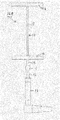
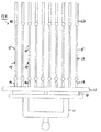
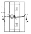
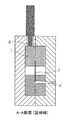
- FIG. 3 is a cross-sectional view taken along line AA during stretching. It is a front view which shows a binding band. It is a side view. It is an enlarged plan view of an insertion hole. It is sectional drawing.
- the present invention is based on the conditions described in claim 1 and the molded product obtained is based on the injection molding method described herein. That is, the present invention is characterized in that when a molded product is injection-molded with PEEK material, the filling peak pressure in the mold is set to 40 to 150 MPa, and this filling peak pressure is 180 to 280 MPa which is a conventional pressure. The pressure is much lower than that, and the molding under this low pressure allows the molded product to have the characteristics of flexibility, stickiness, and elasticity.
- reference numeral 1 denotes a mold product part insert 1, and the mold product part insert 1 is attached to a mounting plate.
- the mold product part insert 1 is provided with a PEEK sprue 2 as a raw material through a mounting plate, and the sprue 2 communicates with a filament (linear body) forming part 3 in the mold product part insert 1. ing.
- the filled PEEK can be processed while the temperature is high, the efficiency is high, and the drawn filament has high strength and does not break or break.
- the assembly 10A of the locking pin material is obtained by carrying out claims 1, 2 and particularly claim 3.
- This assembly 10A has a runner 11, and a sub runner 13 is connected to the runner 11 through multi-point gates 12, 12,.
- a single locking pin member 10, 10,... Is connected from the sub-runner 13 through gates (connecting portions) 14, 14,.
- the above-described gates 14, 14... Are cut by a cutter provided in a known mounting tool of the locking pin members 10, 10,.
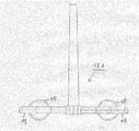
- This locking pin member 10 is integrally provided with horizontal bars 16 and 16a for retaining at both ends of the drawn filament 15, and the horizontal bar 16 is a slit of the wearing tool after the gate 14 is cut.
- the hollow needle is formed by a piston along the filament 15 and restored after the hollow needle passes through the object to prevent it from coming off.
- the assembly 17A is formed by the injection molding method described in claim 4 in particular.
- the assembly 17A has a film gate 18 between the runner 11 and the sub-runner 13.
- the retaining portion 16b is not a simple horizontal bar but a paddle shape, and can be arbitrarily displayed. The action of the horizontal bar 16 is the same as described above.
- FIG. 5 and FIG. 6 show a fastener lock member 19 formed by carrying out claim 5 in particular.
- the fastener lock member 19 has a stretched filament 20, and even if one filament 20 is bent in the middle, two are joined by a U-shaped connecting support member (cover) 21 at the end thereof. Alternatively, a single bent portion may be reinforced by the connection support member 21.
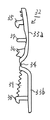
- One end of the filament 20 is integrally provided with an insertion portion 22 having a hooking portion 22a.
- Reference numeral 22b denotes a stopper for the insertion portion 22.
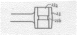
- the other end of the filament 20 is integrally provided with a receiving portion 23 provided with a through hole 23a into which the insertion portion 22 is inserted, and the inner peripheral surface of the through hole 23a has a ring shape.
- a latching portion 23b that is locked by engaging the latching portion 22a of the insertion portion 22 is integrally formed.
- the binding band 24 shown in FIGS. 10 to 14 is formed by carrying out the invention according to claim 1.
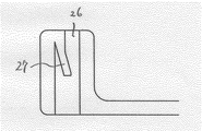
- the binding band 24 has an insertion hole 26 through which the other end is inserted at one end of a band portion 25 having a predetermined width, and a hooking claw 27 is provided in the insertion hole 26.
- ratchet claws 28, 28... are formed at a predetermined pitch on one surface of the band portion 25, that is, the surface on the side in contact with the engagement claws 27.
- guide rails 29 and 29 are formed on the side edges of the surface on which the ratchet claws 28 are formed, and slits 30 through which the guide rails 29 and 29 pass are formed on both sides of the engaging claws 27. , 30 are formed.
- Reference numeral 31 denotes a stopper which is the limit for narrowing the band 25.
- the bag mouth clip 32 shown in FIGS. 15 to 19 is formed by carrying out the invention of claim 1.
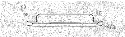
- the bag mouth clip 32 has a pair of clamping pieces 33 a and 33 b via a hinge 34.
- a hooking claw 35, a biting portion 36 to the bag mouth and a support bar 37 are formed on the inner surface of the sandwiching piece 33a.
- the holding piece 33b is formed with a receiving claw 38 that receives the above-mentioned engaging claw 35 and locks it, and a pair of biting portions 39, 39 into the bag mouth.
- the bag mouth opened by the bag mouth clip 32 is pinched and locked, but even if a PEEK material is used, the flexibility of the hinge 34 can be particularly secured, and the elasticity of the hooking claws 35 and the receiving claws 38 can be secured.
- the fastener lock member 40 shown in FIGS. 20 to 22 is formed with the insertion portion 41 and the receiving portion 42 of the insertion portion 41 by carrying out the invention according to claim 1, and each of them is formed as an end of the loop molding material 43.
- a thread is used as the loop molding material 43.
- this yarn can be replaced by plastic fiber.
- the insertion portion 41 is formed with a stepped portion as a hooking portion 41a at the distal end portion, and the distal end has a spherical shape so that the insertion operation into the receiving portion 42 can be easily performed.
- the receiving part 42 has an end face opened so that the insertion part 41 can be inserted.
- a pair of claws are formed inside the opening as a hooking portion 42a with which the hooking portion 41a is hooked.
- 42b is a window hole formed in the receiving part 42, and a locked state can be visually observed and the expansion
- the chain fastener lock member 44 shown in FIG. 23 is formed by carrying out the invention of claim 1, claim 2, claim 5, or claim 6.
- the chain fastener lock member 44 has a chain-shaped loop formed body 45 in which a large number of ring bodies 45a, 45a,.
- One end of the loop molded body 45 is integrally provided with an insertion portion 46 provided with a hooking portion 46a, and the other end is provided with a hooking portion 47a that is hooked with the hooking portion 46a to be locked.
- the receiving part 47 is provided integrally.
- the assembly 48A of the coil springs 48 and 48 shown as FIGS. 24 and 25 is formed by carrying out the invention described in claim 1 or claim 2.
- PEEK material is injected from runners 49, 49 by multi-point gates 49a, 49a, etc., and a coil spring 48 is injection molded.
- the formed coil spring 48 is used as a single product by separating the multi-point gates 49a, 49a,.
- the coil spring 48 is realized by obtaining sufficient flexibility and elasticity by the injection molding method according to the present invention.
- the PEEK material injection molding method and the molded product according to the present embodiment are configured as described above. If the injection molding method described in claims 1 to 6 is performed, in addition to the molded article specifically shown in the embodiment, a product that requires flexibility, elasticity or stickiness is obtained by the PEEK material. be able to.
Landscapes
- Engineering & Computer Science (AREA)
- Mechanical Engineering (AREA)
- Manufacturing & Machinery (AREA)
- Injection Moulding Of Plastics Or The Like (AREA)
- Moulds For Moulding Plastics Or The Like (AREA)
- Slide Fasteners (AREA)
Abstract
PEEK材によって成形品を射出成形するに際し、その充填ピーク圧力を40~150MPaとする。また、この射出成形には多点ゲートを介し、必要に応じて延伸処理、それも金型内延伸加工を施す。これによって得られた成形品は、従来のPEEK材成形品と比べ、PEEK特有の靭性、剛性を保ちながら、はるかに柔軟性、弾発性もしくは粘りを有するものとすることができ、かかる特性を必要とする嵌合によるロック機構、ヒンジ等の多くの成形品を得ることができる。
Description
本発明はポリエーテルエーテルケトン(以下、PEEKと称する)材による射出成形方法及びその射出成形方法によって得られる成形品に関する。
元来、PEEKは靭性が大きく、破断することがなく、重量平均分子量によっては成形条件を広く設定することもできる素材であり、低温、高温に対する耐熱性にも優れている。このPEEKは従来、射出成形によって成形品を製造する場合、靭性の物性を活かすため180~280MPaの高圧力によって行われている。
しかしながら、この射出成形によると、PEEKは靭性、剛性の特性が格別のものとなり、柔軟性、粘りに乏しい物性となってしまい、成形品を製造した場合、衝撃での破損、折損が生じてしまうこととなり、得られる成形品も形状や作用が限定されてしまうものとなっていた。
本発明が解決しようとする問題点は、従来、PEEKを材料として、柔軟性、粘性の物性を保有させた成形品を作ることができなかったという点であり、PEEKを材料とした柔軟性、粘性、弾発性を保有した成形品は存在しなかったという点である。
上記した問題点を解決するため、本発明に係るPEEK材による射出成形方法は、ポリエーテルエーテルケトン(PEEK)によって成形品を射出成形するについて、充填ピーク圧力を40~150MPaとしたことを特徴としている。
また、本発明に係るPEEK材による射出成形方法は、ランナー部材から多点ゲートを介して成形品にPEEK材を充填することを特徴とし、ランナー部材から多点ゲートを介し、さらにサブランナーを経由して成形品にPEEK材を充填することを特徴とし、ランナー部材とサブランナーはフィルムゲートで接続してあることを特徴としている。
さらに、本発明に係るPEEK材による射出成形方法は、PEEK材の射出後に延伸加工を施し、1.2~5倍の長さとし、かつ、径を0.2~1.0mmとすることを特徴とし、前記延伸加工は金型内延伸方法を用いることを特徴としている。
また、本発明に係るPEEK材による射出成形方法によって成形された成形品として、請求項1から4のうちの1項に記載された射出成形方法によって成形された、両端に抜け止め部を一体に備えた係止ピン材としたことを特徴とし、前記した抜け止め部の一つはパドル状に形成されていることを特徴としている。
さらに、本発明に係るPEEK材による射出成形方法によって成形された成形品として、請求項5または6のうち1項に記載された射出成形方法によって、成形された一端には掛合部を一体に備えた挿し込み部を、他端には、その挿し込み部を受け、前記掛合部と掛合してループ状態をロックする掛止部を備えたファスナーロック部材としたことを特徴としている。
そして、本発明に係るPEEK材による射出成形方法によって成形された成形品として、請求項1に記載された射出成形方法によって成形された、一端に掛合爪を備えた挿通孔を備え、前記した掛合爪と接する一面に所定ピッチでラチェット爪を連続して備えた結束バンドとしたことを特徴としている。
また、本発明に係るPEEK材による射出成形方法によって成形された成形品として、請求項1に記載された射出成形方法によって成形された、ヒンジを介して一体に連結された一対の挟持片を有し、その一方の挟持片には掛合爪を、他方の挟持片にはその掛合爪を受け止着する受爪を備えた袋口クリップとしたことを特徴としている。
さらに、本発明に係るPEEK材による射出成形方法によって成形された成形品として、請求項1に記載された射出成形方法によって成形された、掛合部を形成した挿し込み部とその挿し込み部が挿し込まれ、掛合部が掛合する掛止部を形成した受部とを成形品とし、その挿し込み部と受部とをループ成形材の各端部に固着したファスナーロック部材としたことを特徴としている。
そして、本発明に係るPEEK材による射出成形方法によって成形された成形品として、請求項1または請求項2に記載された射出成形方法によって成形された、リング体を連続してつないだチェーン状のループ成形体を有し、そのループ成形体の一端に掛合部を備えた挿し込み部を、他端に、その挿し込み部が挿し込まれ、前記掛合部と掛合する掛止部を備えたチェーンファスナーロック部材としたことを特徴としている。
また、本発明に係るPEEK材による射出成形方法によって成形された成形品として、請求項1または請求項2の射出成形方法によって成形された、コイルスプリングとしたことを特徴としている。
請求項1に記載された発明によれば、PEEK材で射出成形された成形品に柔軟性、粘り、弾発性を保有させることができ、請求項2~4に記載の発明によれば、PEEK材の金型内への充填低圧力を抑えることができ、請求項5~6に記載の発明によれば延伸加工を金型内延伸方法によって行なうことでPEEK材の温度が高いうちに延伸でき、この延伸加工によって成形品の強度が増すこととなる。
請求項7~8に記載の発明によれば、ピン部分は延伸されて強化され、抜け止め部が装着器具のスリットを形成した中空ニードルを通過して復元する際の柔軟性、弾発性が確保できる。
請求項9に記載の発明によれば、挿し込み部における掛合部と受部の掛止部に柔軟性、弾発性を確保し、ループ成形部は延伸加工によって強化される。
請求項10に記載の発明によれば、絞り込み時のバンド部分の柔軟性を確保でき、掛合爪とラチェット爪に柔軟性、弾発性を確保できる。
請求項11に記載の発明によれば、一対の挟持片を連結するヒンジ部に柔軟性と弾発性を確保でき、掛合爪と受爪にも柔軟性と弾発性を確保できる。
請求項12に記載の発明によれば、挿し込み部の掛合部と受部の掛止部に柔軟性、弾発性を確保することができる。
請求項13に記載の発明によれば、挿し込み部の掛合部とその掛止部に柔軟性、弾発性を確保でき、延伸加工を行なうことでチェーンを形成するリング体の径を細くした製品を得ることができる。
請求項14に記載の発明によれば、柔軟性、弾発性を有効に用いることでコイルスプリングの機能を発揮させることができる。
図面として示し、実施例に説明したように構成したことで実現した。
次に、本発明の好ましい実施例を図面を参照して説明する。本発明は請求項1に記載の条件を基本として、得られる成形品はここに記載された射出成形方法を基本とする。即ち、本発明はPEEK材によって成形品を射出成形するについて、金型への充填ピーク圧力を40~150MPaにすることに特徴があり、この充填ピーク圧力は従来行われている圧力の180~280MPaよりもはるかに低圧力となっており、この低圧力下での成形により、成形品には柔軟性、粘り、弾発性の特性を保有させることができることとなる。
そして、必要に応じて行われる延伸処理、それも金型内延伸方法は図7~図9に示される原理による。図7~図9にあって図中1は金型製品部入れ子を示しており、この金型製品部入れ子1は取付板に取り付けされている。この金型製品部入れ子1には原材料となるPEEKのスプルー2が取付板を通して設けられており、このスプルー2は金型製品部入れ子1内のフィラメント(線状体)の成形部3と連通している。この成形部3にPEEKを成形機の充填ピーク圧力40~150MPaで充填した後に、ピストン部材4の操作で金型製品部入れ子1の一方をスライドさせ、成形部3内で成形されたフィラメントを金型原形長さの1.2から5倍の長さに延伸し、フィラメントの径は0.2~1.0mmとする。この金型内延伸方法によると充填されたPEEKの温度が高いうちに処理することができ、効率が良く、延伸されたフィラメントは強度が大きくなり、破断、折損することがない。
また、図1、図2として示すのはタグの吊持用としたり、対象物を包んだ断熱材の接合等々多々の目的に使用することのできる係止ピン材10、10‥の成形品としてのアッセンブリ10Aを示し、この係止ピン材のアッセンブリ10Aは請求項1、請求項2、特には請求項3を実施して得られる。このアッセンブリ10Aはランナー11を有しており、このランナー11から多点のゲート12、12‥を介してサブランナー13が連結されている。
このサブランナー13からはゲート(連結部)14、14‥を介して単品の係止ピン材10、10‥が連結されている。前記したゲート14、14‥は係止ピン材10、10‥の既知の装着用具に備えられたカッターによって切断されて係止ピン材10を単品として使用することができる。この係止ピン材10は延伸処理されたフィラメント15の両端に抜け止め用の横バー16、16aが一体に備えられており、このうち横バー16はゲート14が切断された後に装着用具のスリットを形成した中空ニードル内にフィラメント15に沿ってピストンで押し入れられ、中空ニードルが対象物を通過した後に復元して抜け止めを図ることとなる。
図3、図4として示す係止ピン材17、17‥も使用用途は係止ピン材10と同様ではあるが、特に請求項4に記載された射出成形方法によってアッセンブリ17Aを成形している。また、このアッセンブリ17Aはランナー11とサブランナー13との間はフィルムゲート18を介している。また、抜け止め部16bは単なる横バーではなくパドル状としてあり、任意の表示をすることも可能としている。横バー16の作用は前記と同様である。
図5、図6として示すのは特に請求項5を実施することによって成形されたファスナーロック部材19を示している。このファスナーロック部材19は延伸されたフィラメント20を有しており、このフィラメント20は一本ものを中間で屈曲しても二本をその端部でU字形の連結支持部材(カバー)21でつないでもよく、また、一本ものの屈曲部にこの連結支持部材21で補強してもよい。このフィラメント20の一端には掛合部22aを備えた挿し込み部22が一体的に備えられている。尚、22bは挿し込み部22のストッパである。
フィラメント20の他端には前記した挿し込み部22が挿し込まれる貫通孔23aが設けられた受部23が一体的に備えられており、この貫通孔23aの内周面にはリング状に、挿し込み部22の掛合部22aが掛合してロック状態とされる掛止部23bが一体に形成されている。
図10~図14として示す結束バンド24は請求項1に記載の発明を実施することで成形される。この結束バンド24は所定の幅を有するバンド部25の一方端部に、他端を挿通する挿通孔26を形成し、その挿通孔26には掛合爪27が設けられている。また、バンド部25の一方面、即ち、前記した掛合爪27と接する側の面にはラチェット爪28、28‥が所定のピッチで形成されている。さらに、このラチェット爪28、28‥が形成されている面の側縁にはガイドレール29、29が形成されており、掛合爪27の両側には、このガイドレール29、29が通過するスリット30、30が形成されている。尚、31はバンド25の絞り込みの限度となるストッパである。結束バンド24をこう構成することで掛合爪27やラチェット爪28の柔軟性、弾発性が得られ、バンド部25の絞り込み時の柔軟性が確保できる。
また、図15~図19として示す袋口クリップ32は請求項1に記載の発明を実施することで成形される。この袋口クリップ32は一対の挟持片33aと33bをヒンジ34を介して有している。挟持片33aの内面には掛合爪35及び袋口への喰い込み部36及び支持バー37が形成されている。一方、挟持片33bには前記した掛合爪35を受け、ロック状態とする受爪38と一対の袋口への喰い込み部39、39が形成されている。この袋口クリップ32で開封された袋口を挟持しロックするがPEEK材を用いても、特にヒンジ34の柔軟性を確保でき、掛合爪35と受爪38の弾発性を確保できる。
図20~図22として示すファスナーロック部材40は請求項1に記載の発明を実施することで挿し込み部41とその挿し込み部41の受部42と成形し、各々をループ成形材43の端部に固着したものであり、本実施例にあってはループ成形材43として糸を用いている。勿論この糸はプラスチック製のファイバーに代替することもできる。挿し込み部41は先端部分に掛合部41aとして段部が形成されており、先端は受部42への挿し込み作業が行ない易いように球面状とされている。
受部42は端面が開口されて挿し込み部41が挿し込めるようになっている。この開口の内方には前記した掛合部41aが掛合する掛止部42aとして一対の爪体が形成されている。尚、42bは受部42に形成された窓孔であり、ロック状態を目視でき、また、爪体の拡開作用を容易とする。かかる構成とすることで特に掛止部42aの柔軟性、弾発性を確保できる。
また、図23として示すチェーンファスナーロック部材44は請求項1、請求項2あるいは請求項5、請求項6の発明を実施することで成形される。このチェーンファスナーロック部材44は延伸処理して得られたファイバーをリング状としたリング体45a、45a‥を多数連続したチェーン状のループ成形体45を有している。このループ成形体45の一端には掛合部46aを備えた挿し込み部46が一体的に設けられ、他端には前記した掛合部46aと掛合してロック状態とする掛止部47aを備えた受部47が一体的に備えられている。かかる構成とすることでリング体45a、45aの径の細いものを製作することができ、そのループ成形体45の可撓性も大きなものとすることができる。加えて掛止部47aの柔軟性、弾発性が確保できる。
図24、図25として示すコイルスプリング48、48のアッセンブリ48Aは請求項1あるいは請求項2に記載された発明を実施することで成形される。このアッセンブリ48Aはランナー49、49から多点のゲート49a、49a‥によってPEEK材を射出し、コイルスプリング48を射出成形する。成形されたコイルスプリング48は多点のゲート49a、49a‥をカッターでランナー49から切離するか、あるいは千切り取ることで単品として使用に供される。このコイルスプリング48は本発明に係る射出成形方法により十分な柔軟性と弾発性を得ることで実現されている。
本実施例に係るPEEK材の射出成形方法及びその成形品は上記したように構成されている。請求項1から6に記載された射出成形方法を実施すれば、実施例で具体的に示した成形品のほかにも、PEEK材によって柔軟性、弾発性あるいは粘りが要求される製品を得ることができる。
1 製品部入れ子
2 スプルー
3 成形部
4 ピストン部材
10,17 係止ピン材
10A,17A,48A アッセンブリ
11,49 ランナー
12,14,49a ゲート
13 サブランナー
15,20 フィラメント
16,16a,16b 横バー
18 フィルムゲート
19,40 ファスナーロック部材
21 連結支持部材(カバー)
22,41,46 挿し込み部
22a,41a,46a 掛合部
22b,31 ストッパ
23,42,47 受部
23a 貫通孔
23b,42a,47a 掛止部
24 結束バンド
25 バンド部
26 挿通孔
27,35 掛合爪
28 ラチェット爪
29 ガイドレール
30 スリット
32 袋口クリップ
33a,33b 挟持片
34 ヒンジ
36,39 喰い込み部
37 支持バー
38 受爪
42b 窓孔
44 チェーンファスナーロック部材
45 ループ成形体
45a リング体
48 コイルスプリング
2 スプルー
3 成形部
4 ピストン部材
10,17 係止ピン材
10A,17A,48A アッセンブリ
11,49 ランナー
12,14,49a ゲート
13 サブランナー
15,20 フィラメント
16,16a,16b 横バー
18 フィルムゲート
19,40 ファスナーロック部材
21 連結支持部材(カバー)
22,41,46 挿し込み部
22a,41a,46a 掛合部
22b,31 ストッパ
23,42,47 受部
23a 貫通孔
23b,42a,47a 掛止部
24 結束バンド
25 バンド部
26 挿通孔
27,35 掛合爪
28 ラチェット爪
29 ガイドレール
30 スリット
32 袋口クリップ
33a,33b 挟持片
34 ヒンジ
36,39 喰い込み部
37 支持バー
38 受爪
42b 窓孔
44 チェーンファスナーロック部材
45 ループ成形体
45a リング体
48 コイルスプリング
Claims (14)
- ポリエーテルエーテルケトン(PEEK)によって成形品を射出成形するについて、充填ピーク圧力を40~150MPaとしたことを特徴とするPEEK材による射出成形方法。
- ランナー部材から多点ゲートを介して成形品にPEEK材を充填することを特徴とする請求項1に記載のPEEK材による射出成形方法。
- ランナー部材から多点ゲートを介し、さらにサブランナーを経由して成形品にPEEK材を充填することを特徴とする請求項1または2に記載のPEEK材による射出成形方法。
- ランナー部材とサブランナーはフィルムゲートで接続してあることを特徴とする請求項3に記載のPEEK材による射出成形方法。
- PEEK材の射出後に延伸加工を施し、1.2~5倍の長さとし、かつ、径を0.2~1.0mmとすることを特徴とする請求項1に記載のPEEK材による射出成形方法。
- 前記延伸加工は金型内延伸方法を用いることを特徴とする請求項5に記載のPEEK材による射出成形方法。
- 請求項1から4のうちの1項に記載された射出成形方法によって成形された、両端に抜け止め部を一体に備えた係止ピン材としたことを特徴とする成形品。
- 前記した抜け止め部の一つはパドル状に形成されていることを特徴とする請求項7に記載の係止ピン材。
- 請求項5または6のうち1項に記載された射出成形方法によって、成形された一端には掛合部を一体に備えた挿し込み部を、他端には、その挿し込み部を受け、前記掛合部と掛合してループ状態をロックする掛止部を備えたファスナーロック部材としたことを特徴とする成形品。
- 請求項1に記載された射出成形方法によって成形された、一端に掛合爪を備えた挿通孔を備え、前記した掛合爪と接する一面に所定ピッチでラチェット爪を連続して備えた結束バンドとしたことを特徴とする成形品。
- 請求項1に記載された射出成形方法によって成形された、ヒンジを介して一体に連結された一対の挟持片を有し、その一方の挟持片には掛合爪を、他方の挟持片にはその掛合爪を受け止着する受爪を備えた袋口クリップとしたことを特徴とする成形品。
- 請求項1に記載された射出成形方法によって成形された、掛合部を形成した挿し込み部とその挿し込み部が挿し込まれ、掛合部が掛合する掛止部を形成した受部とを成形品とし、その挿し込み部と受部とをループ成形材の各端部に固着したファスナーロック部材としたことを特徴とする成形品。
- 請求項1または請求項2に記載された射出成形方法によって成形された、リング体を連続してつないだチェーン状のループ成形体を有し、そのループ成形体の一端に掛合部を備えた挿し込み部を、他端に、その挿し込み部が挿し込まれ、前記掛合部と掛合する掛止部を備えたチェーンファスナーロック部材としたことを特徴とする成形品。
- 請求項1または請求項2の射出成形方法によって成形された、コイルスプリングとしたことを特徴とする成形品。
Priority Applications (3)
| Application Number | Priority Date | Filing Date | Title |
|---|---|---|---|
| PCT/JP2015/052031 WO2016120972A1 (ja) | 2015-01-26 | 2015-01-26 | Peek材による射出成形方法及び成形品 |
| EP15879869.4A EP3251815A4 (en) | 2015-01-26 | 2015-01-26 | Injection molding method using peek material and molded items |
| US15/546,457 US20180236702A1 (en) | 2015-01-26 | 2015-01-26 | Injection molding method using peek material and molded item |
Applications Claiming Priority (1)
| Application Number | Priority Date | Filing Date | Title |
|---|---|---|---|
| PCT/JP2015/052031 WO2016120972A1 (ja) | 2015-01-26 | 2015-01-26 | Peek材による射出成形方法及び成形品 |
Publications (1)
| Publication Number | Publication Date |
|---|---|
| WO2016120972A1 true WO2016120972A1 (ja) | 2016-08-04 |
Family
ID=56542631
Family Applications (1)
| Application Number | Title | Priority Date | Filing Date |
|---|---|---|---|
| PCT/JP2015/052031 Ceased WO2016120972A1 (ja) | 2015-01-26 | 2015-01-26 | Peek材による射出成形方法及び成形品 |
Country Status (3)
| Country | Link |
|---|---|
| US (1) | US20180236702A1 (ja) |
| EP (1) | EP3251815A4 (ja) |
| WO (1) | WO2016120972A1 (ja) |
Cited By (2)
| Publication number | Priority date | Publication date | Assignee | Title |
|---|---|---|---|---|
| WO2019181975A1 (ja) | 2018-03-23 | 2019-09-26 | 住友化学株式会社 | 結束バンド |
| JP2020124849A (ja) * | 2019-02-05 | 2020-08-20 | 株式会社トスカバノック | プラスチック製品の成形方法 |
Citations (4)
| Publication number | Priority date | Publication date | Assignee | Title |
|---|---|---|---|---|
| JP2002292711A (ja) * | 2001-04-03 | 2002-10-09 | Asahi Kasei Corp | 射出圧力の設定方法 |
| JP2006291217A (ja) * | 1995-06-09 | 2006-10-26 | Pbi Performance Products Inc | 高充填材入り射出成形用ポリアリールエーテルケトン |
| JP2008024924A (ja) * | 2006-06-22 | 2008-02-07 | Toray Ind Inc | 結束バンド |
| JP2012126441A (ja) * | 2010-12-17 | 2012-07-05 | Toska Co Ltd | 結束バンド |
Family Cites Families (15)
| Publication number | Priority date | Publication date | Assignee | Title |
|---|---|---|---|---|
| US3792134A (en) * | 1969-07-15 | 1974-02-12 | Litton Industrial Products | Method for monitoring product quality in a plastics injection-molding machine |
| JPH0733075B2 (ja) * | 1992-11-05 | 1995-04-12 | 株式会社トスカ | タグピン集合体の製造方法 |
| JP3047732B2 (ja) * | 1994-05-16 | 2000-06-05 | 東洋製罐株式会社 | 二軸延伸ブロー容器の製造方法 |
| US5902534A (en) * | 1994-09-21 | 1999-05-11 | Mitsubishi Engineering-Plastics Corp. | Method of injection-molding thermoplastic resins |
| JP3301873B2 (ja) * | 1994-11-18 | 2002-07-15 | 光洋精工株式会社 | 樹脂巻き部品の成形方法 |
| JP2875773B2 (ja) * | 1994-12-28 | 1999-03-31 | エヌティエヌ株式会社 | 合成樹脂製オイルシールリング |
| JP3538823B2 (ja) * | 1995-04-21 | 2004-06-14 | Nok株式会社 | 樹脂組成物 |
| US6322344B1 (en) * | 1997-09-25 | 2001-11-27 | Mitsubishi Gas Chemical Co., Inc. | Injection molding apparatus for molding multi-layered articles |
| JP3948120B2 (ja) * | 1998-06-15 | 2007-07-25 | ソニー株式会社 | ガスケットとガスケットの成形方法及びこのガスケットを用いた円筒形アルカリ電池 |
| JP4096440B2 (ja) * | 1999-03-11 | 2008-06-04 | 三菱瓦斯化学株式会社 | 多層成形品 |
| EP2546536A4 (en) * | 2010-03-10 | 2014-02-26 | Ntn Toyo Bearing Co Ltd | CAGE AND BALL BEARINGS |
| FR2967073A1 (fr) * | 2010-11-04 | 2012-05-11 | Catherine Cadorel | Materiau greffon de comblement osseux, a usage medical ou veterinaire, son procede d'obtention, le materiau obtenu et ses applications |
| CN102476438A (zh) * | 2010-11-22 | 2012-05-30 | 大连创达技术交易市场有限公司 | 一种碳纤维复合的注塑成型方法 |
| CN102134385B (zh) * | 2011-05-05 | 2012-04-18 | 刘立文 | 一种硫酸钙晶须改性聚醚醚酮复合材料及其制备工艺 |
| US8980146B2 (en) * | 2013-08-01 | 2015-03-17 | Imflux, Inc. | Injection molding machines and methods for accounting for changes in material properties during injection molding runs |
-
2015
- 2015-01-26 US US15/546,457 patent/US20180236702A1/en not_active Abandoned
- 2015-01-26 WO PCT/JP2015/052031 patent/WO2016120972A1/ja not_active Ceased
- 2015-01-26 EP EP15879869.4A patent/EP3251815A4/en not_active Withdrawn
Patent Citations (4)
| Publication number | Priority date | Publication date | Assignee | Title |
|---|---|---|---|---|
| JP2006291217A (ja) * | 1995-06-09 | 2006-10-26 | Pbi Performance Products Inc | 高充填材入り射出成形用ポリアリールエーテルケトン |
| JP2002292711A (ja) * | 2001-04-03 | 2002-10-09 | Asahi Kasei Corp | 射出圧力の設定方法 |
| JP2008024924A (ja) * | 2006-06-22 | 2008-02-07 | Toray Ind Inc | 結束バンド |
| JP2012126441A (ja) * | 2010-12-17 | 2012-07-05 | Toska Co Ltd | 結束バンド |
Non-Patent Citations (1)
| Title |
|---|
| See also references of EP3251815A4 * |
Cited By (4)
| Publication number | Priority date | Publication date | Assignee | Title |
|---|---|---|---|---|
| WO2019181975A1 (ja) | 2018-03-23 | 2019-09-26 | 住友化学株式会社 | 結束バンド |
| US11738921B2 (en) | 2018-03-23 | 2023-08-29 | Sumitomo Chemical Company, Limited | Banding band |
| JP2020124849A (ja) * | 2019-02-05 | 2020-08-20 | 株式会社トスカバノック | プラスチック製品の成形方法 |
| JP7257802B2 (ja) | 2019-02-05 | 2023-04-14 | 株式会社トスカバノック | プラスチック製品の成形方法 |
Also Published As
| Publication number | Publication date |
|---|---|
| EP3251815A1 (en) | 2017-12-06 |
| EP3251815A4 (en) | 2018-09-05 |
| US20180236702A1 (en) | 2018-08-23 |
Similar Documents
| Publication | Publication Date | Title |
|---|---|---|
| US6435940B1 (en) | Garment hook | |
| US20250026054A1 (en) | Self-releasing tie | |
| US9033146B2 (en) | Loop clips for golf bags and methods to manufacture golf bags | |
| AU2016201085A1 (en) | Carabiner Key Ring | |
| JP2012235911A (ja) | 止着用クリップ | |
| US20160235233A1 (en) | Molded composite garment hanger and molds for manufacturing the same | |
| MX2015006622A (es) | Elementos de enganche moldeados y su procedimiento de fabricacion. | |
| EP3251815A1 (en) | Injection molding method using peek material and molded items | |
| US11793279B2 (en) | Fasteners | |
| US20190021453A1 (en) | Slide fastener tape with molded zipper teeth and methods of making same | |
| JP5609752B2 (ja) | 止着用クリップ | |
| US9944028B1 (en) | Methods for manufacturing slide fastener with overmolded components | |
| SG11201909020TA (en) | Molded article and method for producing same | |
| JP2020124849A (ja) | プラスチック製品の成形方法 | |
| EP2164768B1 (en) | Buckle and fastener using the same | |
| US7424770B2 (en) | Attachment comprising a flexible cord | |
| KR20170061936A (ko) | 사출품 조립 구조 | |
| KR101619913B1 (ko) | 결착용 행거 및 그 제조 방법 | |
| KR101402009B1 (ko) | 지지끈 결속핀 | |
| WO2018091952A1 (en) | Clothes hangers | |
| JP4996337B2 (ja) | エラストマーで成形したアタッチ部材の製造方法 | |
| US2811749A (en) | Method of making a barrette | |
| WO2013109496A1 (en) | Nested zipper puller | |
| KR970008239B1 (ko) | 계지편 집합체(係止片集合體)의 제조 방법 | |
| JPS5932303B2 (ja) | 冷延伸可能な打出しピンマガジンの製造方法 |
Legal Events
| Date | Code | Title | Description |
|---|---|---|---|
| 121 | Ep: the epo has been informed by wipo that ep was designated in this application |
Ref document number: 15879869 Country of ref document: EP Kind code of ref document: A1 |
|
| REEP | Request for entry into the european phase |
Ref document number: 2015879869 Country of ref document: EP |
|
| WWE | Wipo information: entry into national phase |
Ref document number: 15546457 Country of ref document: US |
|
| NENP | Non-entry into the national phase |
Ref country code: DE |
|
| NENP | Non-entry into the national phase |
Ref country code: JP |