WO2016117481A1 - 塗布装置及び塗布方法 - Google Patents
塗布装置及び塗布方法 Download PDFInfo
- Publication number
- WO2016117481A1 WO2016117481A1 PCT/JP2016/051199 JP2016051199W WO2016117481A1 WO 2016117481 A1 WO2016117481 A1 WO 2016117481A1 JP 2016051199 W JP2016051199 W JP 2016051199W WO 2016117481 A1 WO2016117481 A1 WO 2016117481A1
- Authority
- WO
- WIPO (PCT)
- Prior art keywords
- discharge
- nozzle
- coating liquid
- position coordinates
- nozzles
- Prior art date
- Legal status (The legal status is an assumption and is not a legal conclusion. Google has not performed a legal analysis and makes no representation as to the accuracy of the status listed.)
- Ceased
Links
Images



Classifications
-
- B—PERFORMING OPERATIONS; TRANSPORTING
- B05—SPRAYING OR ATOMISING IN GENERAL; APPLYING FLUENT MATERIALS TO SURFACES, IN GENERAL
- B05C—APPARATUS FOR APPLYING FLUENT MATERIALS TO SURFACES, IN GENERAL
- B05C5/00—Apparatus in which liquid or other fluent material is projected, poured or allowed to flow on to the surface of the work
-
- B—PERFORMING OPERATIONS; TRANSPORTING
- B05—SPRAYING OR ATOMISING IN GENERAL; APPLYING FLUENT MATERIALS TO SURFACES, IN GENERAL
- B05C—APPARATUS FOR APPLYING FLUENT MATERIALS TO SURFACES, IN GENERAL
- B05C5/00—Apparatus in which liquid or other fluent material is projected, poured or allowed to flow on to the surface of the work
- B05C5/02—Apparatus in which liquid or other fluent material is projected, poured or allowed to flow on to the surface of the work the liquid or other fluent material being discharged through an outlet orifice by pressure, e.g. from an outlet device in contact or almost in contact, with the work
-
- B—PERFORMING OPERATIONS; TRANSPORTING
- B05—SPRAYING OR ATOMISING IN GENERAL; APPLYING FLUENT MATERIALS TO SURFACES, IN GENERAL
- B05C—APPARATUS FOR APPLYING FLUENT MATERIALS TO SURFACES, IN GENERAL
- B05C11/00—Component parts, details or accessories not specifically provided for in groups B05C1/00 - B05C9/00
- B05C11/10—Storage, supply or control of liquid or other fluent material; Recovery of excess liquid or other fluent material
-
- B—PERFORMING OPERATIONS; TRANSPORTING
- B05—SPRAYING OR ATOMISING IN GENERAL; APPLYING FLUENT MATERIALS TO SURFACES, IN GENERAL
- B05D—PROCESSES FOR APPLYING FLUENT MATERIALS TO SURFACES, IN GENERAL
- B05D1/00—Processes for applying liquids or other fluent materials
- B05D1/26—Processes for applying liquids or other fluent materials performed by applying the liquid or other fluent material from an outlet device in contact with, or almost in contact with, the surface
-
- B—PERFORMING OPERATIONS; TRANSPORTING
- B41—PRINTING; LINING MACHINES; TYPEWRITERS; STAMPS
- B41J—TYPEWRITERS; SELECTIVE PRINTING MECHANISMS, i.e. MECHANISMS PRINTING OTHERWISE THAN FROM A FORME; CORRECTION OF TYPOGRAPHICAL ERRORS
- B41J2/00—Typewriters or selective printing mechanisms characterised by the printing or marking process for which they are designed
- B41J2/005—Typewriters or selective printing mechanisms characterised by the printing or marking process for which they are designed characterised by bringing liquid or particles selectively into contact with a printing material
- B41J2/01—Ink jet
- B41J2/015—Ink jet characterised by the jet generation process
- B41J2/04—Ink jet characterised by the jet generation process generating single droplets or particles on demand
-
- H—ELECTRICITY
- H05—ELECTRIC TECHNIQUES NOT OTHERWISE PROVIDED FOR
- H05K—PRINTED CIRCUITS; CASINGS OR CONSTRUCTIONAL DETAILS OF ELECTRIC APPARATUS; MANUFACTURE OF ASSEMBLAGES OF ELECTRICAL COMPONENTS
- H05K3/00—Apparatus or processes for manufacturing printed circuits
- H05K3/10—Apparatus or processes for manufacturing printed circuits in which conductive material is applied to the insulating support in such a manner as to form the desired conductive pattern
Definitions
- the present invention relates to a coating apparatus and a coating method for applying a coating liquid to a plate-like or sheet-like object.
- a coating liquid is discharged from a nozzle such as an ink jet and applied to the substrate.
- a nozzle such as an ink jet
- the discharge timing is controlled so that the coating liquid is discharged sequentially from the nozzles provided in the head The circuit is formed.
- Japanese Patent Application Laid-Open No. 2004-290958 describes a configuration in which a bitmap having pixels that are a plurality of unit areas in a lattice shape is set, and the discharge timing is controlled to discharge the coating liquid to the set pixel positions. Has been. In addition, it has been conventionally performed that a plurality of nozzles are provided in the head and the ejection timing of each nozzle is set by image data such as a bitmap.
- the discharge timing control in which a conventional bitmap is set will be described with reference to FIG.
- the head 3 is provided with five nozzles 41 to 45, and the head 3 is configured to discharge the coating liquid from the nozzles 41 to 45 while moving in the application direction.
- the ejection drive waveform is generated for all the grids in the column perpendicular to the application direction of the bitmap, but each nozzle 41 to 45 moves to the position set in the bitmap (the position of the filled grid in FIG. 6). In this case, the coating liquid is discharged only from the corresponding nozzles 41 to 45. Then, by changing the setting of the bitmap, the discharge position can be freely determined for each lattice, and the shape to be applied to the substrate can be freely determined.
- the application while the head 3 moves in the application direction is not only an application in which a straight line in the application direction or a direction orthogonal to the application direction is drawn, but also a straight line that is slightly inclined from the direction orthogonal to the application direction (that is, obliquely) There is also an application that draws a straight line). In this case, it is necessary not to continuously discharge the coating liquid with one nozzle 41 to 45 but to discharge the coating liquid with different nozzles 41 to 45 in order.
- the coating liquid When the coating liquid is discharged from the nozzles 41 to 45, for example, the landed droplets may spread to a diameter of about 20 ⁇ m on the surface to be applied. In this case, the liquid is continuously applied from the same nozzles 41 to 45 in the coating direction. In order to draw a straight line without a chip, the coating liquid may be discharged at intervals of about 20 ⁇ m. However, when applying an obliquely smooth line, high resolution between different nozzles is required, and a coating position resolution of about 1 ⁇ m is required.
- the discharge drive waveform is generated at all grid positions in the column including the nozzles that do not discharge as described above.
- the time required for one cycle of the waveform needs to be within the moving time corresponding to the lattice size.
- One cycle of this ejection drive waveform is determined by the volume of the coating liquid to be ejected, and it is not easy to shorten the time required for one cycle.
- the application speed (Lattice size) / (Discharge drive waveform time) ⁇ Equation 1
- the application position resolution that is, the lattice size is 1 ⁇ m and the ejection drive waveform time is 50 ⁇ sec
- the application speed is 20 mm / sec.
- the coating speed is defined by the above equation 1, even if the cycle time of the ejection drive waveform is shortened and the lattice size is made fine to improve the coating position resolution, the coating speed is lowered and the coating speed is increased. For this reason, there is a problem in that the resolution of the coating position is reduced if the lattice size is made coarse.
- An object of the present invention is to solve such problems and improve the application position resolution and improve the application speed.
- the present invention relates to a nozzle for discharging a coating liquid, a head for holding a plurality of nozzles, and the head and a coating object relative to each other so as to move the head to a coating liquid discharging position.
- an arbitration unit for holding the discharge position coordinates in the register in advance until the position detection unit detects a position corresponding to the discharge position coordinates, and a register for holding the discharge position coordinates.
- a coating apparatus characterized in that a discharge drive waveform generating unit which generates an ejection driving waveform for discharging a coating liquid from the nozzle when it is determined that.
- the ejection drive waveform is generated for each nozzle, not for each bitmap of the bitmap, and the interval is the ejection interval for the same nozzle, the distance that the head can move in the time required for one cycle of the ejection drive waveform becomes longer. Application speed can be improved.
- the discharge position coordinates and the position detection unit detect the discharge position coordinates for discharging the coating liquid by reading them from the storage unit and holding them in the register in advance.
- the coating speed can be improved by discharging the coating liquid by comparing the position of the driving unit with the high speed.
- the register may be configured by a shift register, and the shift register may be configured to hold a plurality of discharge position coordinates.
- the time interval at which the register updates the discharge position coordinate output is shorter than the time interval at which the register holds the discharge position coordinate.
- the position detection unit may be an encoder.
- the encoder may be a rotary encoder or a linear encoder depending on the configuration of the drive unit.
- the present invention provides a nozzle that discharges a coating liquid, a head that holds a plurality of nozzles, and the head and a coating object that move the head to a coating liquid discharge position.
- a drive unit that relatively moves the position, a position detection unit that detects the position of the head, a storage unit that stores discharge position coordinates for discharging the coating liquid for each nozzle, and the nozzle that is read from the storage unit for each nozzle
- a register that holds discharge position coordinates for each nozzle; an arbitration unit that holds the discharge position coordinates in the register in advance until the position detection unit detects a position corresponding to the discharge position coordinates; and
- a comparator provided for each of the nozzles for comparing the discharge position coordinates of each of the held nozzles and the position detected by the position detection unit. If it is determined that the position be ejected to, it is to provide a coating method characterized by discharging a coating liquid from the nozzle.
- the ejection drive waveform is generated for each nozzle, not for each bitmap of the bitmap, and the interval is the ejection interval for the same nozzle, the distance that the head can move in the time required for one cycle of the ejection drive waveform becomes longer. Application speed can be improved.
- the discharge position coordinates and the position detection unit detect the discharge position coordinates for discharging the coating liquid by reading them from the storage unit and holding them in the register in advance.
- the coating speed can be improved by discharging the coating liquid by comparing the position of the driving unit with the high speed.
- the nozzle that discharges the coating liquid As described above, the nozzle that discharges the coating liquid, the head that holds a plurality of the nozzles, the drive unit that relatively moves the head and the application target so as to move the head to the discharge position of the coating liquid, A position detection unit for detecting the position of the head, a storage unit for storing the discharge position coordinates for discharging the coating liquid for each nozzle, and the discharge position coordinates for each nozzle read from the storage unit are held for each nozzle.
- an arbitration unit that holds the discharge position coordinates in advance in the register until the position detection unit detects a position corresponding to the discharge position coordinates, and the discharge of each nozzle held in the register
- the coating apparatus characterized by comprising a case from the nozzle and ejection drive waveform generator for generating a drive waveform for discharging a coating solution, to improve the coating position resolution, and it is possible to improve the coating speed.
- a position detection unit that detects the discharge position coordinates for discharging the coating liquid for each nozzle, and a register that holds the discharge position coordinates for each nozzle read from the storage unit for each nozzle.
- An arbitration unit that holds the discharge position coordinates in the register in advance until the position detection unit detects a position corresponding to the discharge position coordinates; and the discharge position coordinates of the nozzles held in the register
- a comparator provided for each of the nozzles for comparing the positions detected by the position detection unit, and as a result of comparison by each of the comparators, it is determined that the coating liquid should be discharged To, by a coating method characterized by discharging a coating liquid from the nozzle, thereby improving the coating position resolution, and it is possible to improve the coating speed.
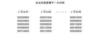
- summary of this invention The figure which shows the example of discharge position coordinate data.
- FIG. 1 shows an outline of coating liquid discharge according to the present invention
- FIG. 2 shows an example of discharge position coordinate data stored in a storage unit
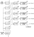
- FIG. 3 shows a control circuit in Embodiment 1 of the present invention
- FIG. 4 shows the coating liquid discharge timing of the present invention.
- the head 3 includes five nozzles 41 to 45, and each of the nozzles 41 to 45 is an ink jet type nozzle.
- the head 3 is moved in the application direction by a drive unit (not shown), and when a position detection unit (not shown) detects a predetermined discharge position, discharges the coating liquid from the nozzles 41 to 45 to form a circuit on the substrate.
- a position detection unit not shown
- the number of nozzles is not limited to five, and may be six or more or four or less as long as it is plural.
- the bitmap size is the application position resolution. For example, if the bitmap is expressed in 5080 dpi (dot per inch), the resolution is about 5 ⁇ m. there were.
- the discharge position coordinates are stored in the storage unit for each nozzle, and the position detected by the position detection unit is compared with the discharge position coordinates to be a position where the coating liquid should be discharged.
- the resolution of the position detection unit can be set as the application position resolution.
- an encoder provided in the drive unit is used as the position detection unit, and a high resolution of about 0.5 ⁇ m can be obtained.
- the ejection position coordinates coincide with the position detected by the position detection unit.
- the discharge position coordinates may coincide with a value obtained by adding an offset to the position detected by the position detection unit.
- the offset value may be time or the number of encoder pulses.
- the position detection unit is not limited to the encoder, and may be a unit that detects an object such as a mark using a TV camera or an optical sensor. By using a TV camera or an optical sensor, the position detection resolution can be further improved.
- Application speed (Same nozzle discharge interval) / (Discharge drive waveform time) ... Formula 2
- the discharge interval with the same nozzle can be set to 20 ⁇ m, which is a discharge interval at which a straight line can be applied in the application direction without any chipping. Therefore, when the discharge drive waveform time is 50 ⁇ sec, it becomes 400 mm / sec. It can be much faster.
- the first embodiment of the present invention includes registers 11 to 15 for each nozzle as shown in FIG.
- the arbitration unit 2 reads and holds the ejection position coordinates from the storage unit.
- the discharge position coordinates held in the registers 11 to 15 are input to one of the corresponding comparators 21 to 25 among the comparators 21 to 25 provided for each nozzle.
- the pulses output from the position detection unit are counted by the counter 1 and the position of the drive unit is input to the other of all the comparators 21 to 25.
- Each of the comparators 21 to 25 compares the position of the drive unit detected by the position detection unit with the discharge position coordinates held in the corresponding registers 11 to 15, and if they match, the corresponding discharge drive waveform generation unit 31 is matched. ⁇ 35 are driven to generate a discharge drive waveform for each nozzle, and the coating liquid is discharged from the corresponding nozzles 41 ⁇ 45. Thereafter, the registers 11 to 15 hold new ejection position coordinates, thereby updating the output data of the registers 11 to 15 to prepare for ejection at the new position.
- the coating liquid discharge timing will be described with reference to FIG. FIG. 4 shows the coating liquid discharge timing at the nozzle 41 and the nozzle 42 as an example, but the same applies to the nozzles 43 to 45.
- the counter 1 counts the output pulses of the position detection unit, outputs timings T1, T2,... Tn,... Tm corresponding to the moving position of the head 3, and inputs them to the other one of the comparators 21-25. Yes.
- the resolution of the timing counted by the counter 1 corresponds to the resolution of the position detection unit (encoder in the first embodiment).
- the discharge position coordinate T1 for the nozzle 41 is read from the storage unit, held in the register 11, and input to one side of the comparator 21. Then, when the counter 1 outputs the timing T1 and inputs it to the other side of the comparator 21, the comparator 21 determines that they match and outputs a signal to the ejection drive waveform generation unit 31, whereby the nozzle 41.
- the discharge driving waveform is output to the liquid and the coating liquid is discharged.
- the ejection position coordinate T2 of the nozzle 42 is read from the storage unit and held in the register 12, and one of the comparators 22 To enter. Then, when the counter 1 counts the timing T 2 and inputs it to the other side of the comparator 22, the comparator 22 determines that both are coincident with each other, outputs a signal to the ejection drive waveform generation unit 32, and outputs it to the nozzle 42. On the other hand, a discharge driving waveform is output, and the coating liquid is discharged from the nozzle 42.
- the counter 1 reads the discharge position coordinates Tn for the nozzle 41 from the storage unit and holds it in the register 11 and inputs it to one side of the comparator 21.
- the comparator 21 determines that the two match and outputs a signal to the ejection drive waveform generation unit 31, and the ejection drive waveform to the nozzle 41. And the coating liquid is discharged from the nozzle 41.
- the discharge position coordinates Tm for the nozzle 42 are read from the storage unit and held in the register 12 and input to one of the comparators 22, so that the counter 1 has the timing Tm. Is counted and input to the other side of the comparator 22, the comparator 22 determines that they match and outputs a signal to the discharge drive waveform generation unit 32, and outputs a discharge drive waveform to the nozzle 42. Then, the coating liquid is discharged from the nozzle 42.
- the registers 11 to 15, the comparators 21 to 25, and the ejection drive waveform generation units 31 to 35 are provided for each nozzle, so that the counter 1 is at a position corresponding to the ejection position coordinates.
- the discharge position coordinates T1 are held in the register 11 in advance, and before the counter 1 counts the timing T2, which is a position corresponding to the discharge position coordinates, the discharge position coordinates are stored in the register 12 in advance.
- the coating liquid can be discharged from the nozzle 41 and the nozzle 42, which are different nozzles, at the timings T1 and T2 corresponding to the resolution of the position detection unit.
- the resolution can be improved to 0.5 ⁇ m, which is the resolution of the position detector.
- the discharge interval at the same nozzle can be set to 20 ⁇ m, which is a discharge interval necessary for applying a straight line in the application direction
- the application speed when the discharge drive waveform time is 50 ⁇ sec is the above formula. 2 is 400 mm / sec, which is significantly faster than the conventional 20 mm / sec.
- the application position resolution can be the resolution of the encoder that is the position detection unit, it can be improved to 0.5 ⁇ m from the conventional 1 ⁇ m.
- Example 2 of the present invention will be described with reference to FIG.
- the control circuit according to the second embodiment is almost the same as the control circuit according to the first embodiment, except that the registers 111 to 115 are provided instead of the registers 11 to 15, and the others are the same.
- the arbitration unit 2 can read and hold the discharge position coordinates from the storage unit.
- the outputs of the registers 111 to 115 are input to one of the comparators 21 to 25, and can be compared with the positions detected by the position detector as in the first embodiment.
- the registers 111 to 115 are constituted by FIFO shift registers, and the registers 111 to 115 can hold a plurality of discharge position coordinates. Of the plurality of held discharge position coordinates, the first held one is input to the comparators 21 to 25. When one comparison is performed by the comparator, a signal (not shown) is input to the registers 111 to 115. The discharge position coordinates in .about.115 are shifted, and the next held discharge position coordinates are input to the comparators 21 to 25.
- the arbiter 2 receives the information from the registers 111 to 115 when the plurality of discharge position coordinates held in the registers 111 to 115 are shifted, and holds the new discharge position coordinates in the registers 111 to 115.
- Example 2 since the discharge interval with the same nozzle can be set to 20 ⁇ m, the application speed when the discharge drive waveform time is 50 ⁇ sec is defined by the above-mentioned formula 2, and becomes 400 mm / sec, which is 20 mm / sec in the related art. It can be much faster. Also, since the application position resolution can be the resolution of the encoder which is the position detection unit, it can be improved to 0.5 ⁇ m compared to the conventional 1 ⁇ m.
- the present invention can be widely applied to a coating apparatus and a coating method for applying a coating liquid to a plate-like or sheet-like object.
Landscapes
- Engineering & Computer Science (AREA)
- Manufacturing & Machinery (AREA)
- Microelectronics & Electronic Packaging (AREA)
- Coating Apparatus (AREA)
- Application Of Or Painting With Fluid Materials (AREA)
Abstract
板状又はシート状の対象物に塗液を塗布するものにおいて、塗布位置分解能を向上させるとともに、塗布速度を向上させる。具体的には、塗布装置において、塗液を吐出するノズルと、前記ノズルを複数保持するヘッドと、前記ヘッドを塗液の吐出位置まで移動させるよう前記ヘッドと塗布対象物とを相対移動させる駆動部と、前記ヘッドの前記塗布対象物との相対位置を検出する位置検出部と、塗液を吐出する吐出位置座標を前記ノズル毎に記憶する記憶部と、前記記憶部から読み出した前記ノズル毎の前記吐出位置座標を前記ノズル毎に保持するレジスタと、前記位置検出部が前記吐出位置座標に相当する位置を検出するまでに、予め前記吐出位置座標を前記レジスタに保持させる調停部と、前記レジスタに保持された前記各ノズルの前記吐出位置座標と前記位置検出部が検出した位置を比較する前記ノズル毎に設けた比較器と、前記各比較器で比較した結果、塗液を吐出すべき位置であると判断した場合に当該ノズルから塗液を吐出する駆動波形を生成する吐出駆動波形生成部とを備える構成とした。
Description
本発明は、板状又はシート状の対象物に塗液を塗布する塗布装置及び塗布方法に関するものである。
従来より、有機ELやタッチパネルの基板上に回路を形成するために、インクジェット等のノズルから塗液を吐出して基板に塗布することが行われている。回路を形成するためには、自由に塗布形状が描けることが求められ、ヘッドを移動させながら決められた位置に到達したら、ヘッドに備えたノズルから順次塗液を吐出するように吐出タイミングを制御して回路を形成している。
特開2004-290958号公報には、格子状の複数の単位領域であるピクセルを有するビットマップを設定して、設定されたピクセル位置に塗液を吐出するように吐出タイミングを制御した構成が記載されている。また、ヘッドに複数のノズルを備えて、それぞれのノズルの吐出タイミングをビットマップなどの画像データで設定することも従来行われている。
従来のビットマップを設定した吐出タイミング制御について、図6を用いて説明する。ヘッド3には5つのノズル41~45が設けられていてヘッド3が塗布方向に移動しながら各ノズル41~45から塗液を吐出するように構成されている。吐出駆動波形はビットマップの塗布方向に直交する当該縦列の全ての格子に生成されるが、ビットマップに設定された位置(図6における塗りつぶされた格子の位置)に各ノズル41~45が移動したときに該当するノズル41~45からのみ塗液を吐出するように構成されている。そして、ビットマップの設定を変更することにより、格子毎に自由に吐出位置を決めることができ、基板に塗布する形状を自由に決めることができる。
ヘッド3が塗布方向へ移動しながらの塗布には塗布方向又は塗布方向に直交する方向の直線を描画するような塗布だけでなく、塗布方向に直交する方向から少し角度のついた直線(すなわち斜め直線)を描画するような塗布もあり、その場合は、1つのノズル41~45で連続的に塗液を吐出するのではなく、順に異なるノズル41~45で塗液を吐出する必要がある。
ノズル41~45から塗液を吐出すると塗布対象となる面ではたとえば着弾した液滴が直径20μmくらいに広がる場合があり、その場合においては、同一ノズル41~45から塗布方向に連続的に塗布し、欠けの無い直線を描画するには、およそ20μmおきに塗液を吐出すればよい。しかし、斜めに滑らかな形状の線を塗布する場合は異なるノズル間での高分解能が必要で、およそ1μm程度の塗布位置分解能が要求される。
しかしながら、ビットマップなどの画像データで吐出位置が設定されている場合は、既に述べたように吐出しないノズルも含めて当該縦列のすべての格子位置で吐出駆動波形が生成されているので、吐出駆動波形の1サイクルに要する時間が格子サイズに相当する移動時間内に収まっている必要がある。この吐出駆動波形の1サイクルは吐出する塗液の容量で定まっており、1サイクルに要する時間を短縮することは容易ではない。
また、吐出駆動波形の1サイクルに相当する時間にヘッドが塗布しながら移動できる距離はビットマップを構成する格子サイズとなるため、塗布速度は、
塗布速度 = (格子サイズ)/(吐出駆動波形時間)・・・・・・式1
で規定され、塗布位置分解能すなわち格子サイズを1μm、吐出駆動波形時間を50μsecとすると塗布速度は20mm/secとなる。
また、吐出駆動波形の1サイクルに相当する時間にヘッドが塗布しながら移動できる距離はビットマップを構成する格子サイズとなるため、塗布速度は、
塗布速度 = (格子サイズ)/(吐出駆動波形時間)・・・・・・式1
で規定され、塗布位置分解能すなわち格子サイズを1μm、吐出駆動波形時間を50μsecとすると塗布速度は20mm/secとなる。
塗布速度が上記の式1で規定されるため、吐出駆動波形の1サイクル時間を短縮し格子サイズを細かくして塗布位置分解能を向上させたとしても塗布速度が低下し、塗布速度を高速化するために格子サイズを粗くすれば、塗布位置分解能が低下するという問題があった。
本発明は、このような問題を解決して、塗布位置分解能を向上させるとともに、塗布速度を向上させることを課題とする。
上記の課題を解決するために本発明は、塗液を吐出するノズルと、前記ノズルを複数保持するヘッドと、前記ヘッドを塗液の吐出位置まで移動させるよう前記ヘッドと塗布対象物とを相対移動させる駆動部と、前記ヘッドの位置を検出する位置検出部と、塗液を吐出する吐出位置座標を前記ノズル毎に記憶する記憶部と、前記記憶部から読み出したノズル毎の前記吐出位置座標を前記ノズル毎に保持するレジスタと、前記位置検出部が前記吐出位置座標に相当する位置を検出するまでに、予め前記吐出位置座標を前記レジスタに保持させる調停部と、前記レジスタに保持された前記各ノズルの前記吐出位置座標と前記位置検出部が検出した位置を比較する前記ノズル毎に設けた比較器と、前記各比較器で比較した結果、塗液を吐出すべき位置であると判断した場合に当該ノズルから塗液を吐出する吐出駆動波形を生成する吐出駆動波形生成部とを備えたことを特徴とする塗布装置を提供するものである。
この構成により、一のノズルによる吐出駆動波形の1サイクルに制限を受けることがなく、位置検出部の分解能で、他のノズルによる吐出駆動波形を生成することができる。したがって、斜め直線の塗布時に必要となる異なるノズルでの塗布位置分解能を位置検出部の分解能まで向上できる。
また、吐出駆動波形の生成はビットマップの格子毎ではなくノズル毎となり、その間隔は同一ノズルでの吐出間隔となるから、吐出駆動波形の1サイクルに要する時間にヘッドが移動できる距離が長くなり、塗布速度を向上できる。
さらに、記憶部の読み出しに比較的長い時間を要する場合でも、塗液を吐出する吐出位置座標を記憶部から読み出して予めレジスタに保持しておくことにより、吐出位置座標と、位置検出部が検出した駆動部の位置とを高速に比較して塗液を吐出することで塗布速度を向上できる。
また、前記レジスタはシフトレジスタで構成し、当該シフトレジスタは複数の吐出位置座標を保持するように構成してもよい。
この構成により、一部液滴を密集させて塗布を行う部分があり、その部分において、レジスタが吐出位置座標出力を更新する時間間隔の方がレジスタへ吐出位置座標を保持させる時間間隔よりも短い場合であっても、予め複数の吐出位置座標が保持されているので、途切れることなく吐出位置座標と検出された駆動部の位置とを比較器で比較して塗液を吐出することができる。
前記位置検出部は、エンコーダで構成してもよい。エンコーダは、駆動部の構成により、ロータリーエンコーダでもリニアエンコーダでもよい。
位置検出部をエンコーダで構成することにより、低コストで構成することができる。
また、上記の課題を解決するために本発明は、塗液を吐出するノズルと、前記ノズルを複数保持するヘッドと、前記ヘッドを塗液の吐出位置まで移動させるよう前記ヘッドと塗布対象物とを相対移動させる駆動部と、前記ヘッドの位置を検出する位置検出部と、塗液を吐出する吐出位置座標を前記ノズル毎に記憶する記憶部と、前記記憶部から読み出した前記ノズル毎の前記吐出位置座標を前記ノズル毎に保持するレジスタと、前記位置検出部が前記吐出位置座標に相当する位置を検出するまでに、予め前記吐出位置座標を前記レジスタに保持させる調停部と、前記レジスタに保持された前記各ノズルの前記吐出位置座標と前記位置検出部が検出した位置を比較する前記ノズル毎に設けた比較器とを備え、前記各比較器で比較した結果、塗液を吐出すべき位置であると判断した場合に、当該ノズルから塗液を吐出することを特徴とする塗布方法を提供するものである。
この構成により、一のノズルによる吐出駆動波形の1サイクルに制限を受けることがなく、位置検出部の分解能で、他のノズルによる吐出駆動波形を生成することができる。したがって、斜め直線の塗布時に必要となる異なるノズルでの塗布位置分解能を位置検出部の分解能まで向上できる。
また、吐出駆動波形の生成はビットマップの格子毎ではなくノズル毎となり、その間隔は同一ノズルでの吐出間隔となるから、吐出駆動波形の1サイクルに要する時間にヘッドが移動できる距離が長くなり、塗布速度を向上できる。
さらに、記憶部の読み出しに比較的長い時間を要する場合でも、塗液を吐出する吐出位置座標を記憶部から読み出して予めレジスタに保持しておくことにより、吐出位置座標と、位置検出部が検出した駆動部の位置とを高速に比較して塗液を吐出することで塗布速度を向上できる。
上記のように、塗液を吐出するノズルと、前記ノズルを複数保持するヘッドと、前記ヘッドを塗液の吐出位置まで移動させるよう前記ヘッドと塗布対象物とを相対移動させる駆動部と、前記ヘッドの位置を検出する位置検出部と、塗液を吐出する吐出位置座標を前記ノズル毎に記憶する記憶部と、前記記憶部から読み出した前記ノズル毎の前記吐出位置座標を前記ノズル毎に保持するレジスタと、前記位置検出部が前記吐出位置座標に相当する位置を検出するまでに、予め前記吐出位置座標を前記レジスタに保持させる調停部と、前記レジスタに保持された前記各ノズルの前記吐出位置座標と前記位置検出部が検出した位置を比較する前記ノズル毎に設けた比較器と、前記各比較器で比較した結果、塗液を吐出すべき位置であると判断した場合に当該ノズルから塗液を吐出する駆動波形を生成する吐出駆動波形生成部とを備えたことを特徴とする塗布装置により、塗布位置分解能を向上させ、かつ塗布速度を向上させることができる。
また、塗液を吐出するノズルと、前記ノズルを複数保持するヘッドと、前記ヘッドを塗液の吐出位置まで移動させるよう前記ヘッドと塗布対象物とを相対移動させる駆動部と、前記ヘッドの位置を検出する位置検出部と、塗液を吐出する吐出位置座標を前記ノズル毎に記憶する記憶部と、前記記憶部から読み出した前記ノズル毎の前記吐出位置座標を前記ノズル毎に保持するレジスタと、前記位置検出部が前記吐出位置座標に相当する位置を検出するまでに、予め前記吐出位置座標を前記レジスタに保持させる調停部と、前記レジスタに保持された前記各ノズルの前記吐出位置座標と前記位置検出部が検出した位置を比較する前記ノズル毎に設けた比較器とを備え、前記各比較器で比較した結果、塗液を吐出すべき位置であると判断した場合に、当該ノズルから塗液を吐出することを特徴とする塗布方法により、塗布位置分解能を向上させ、かつ塗布速度を向上させることができる。
図1~図4を用いて、本発明の塗布装置及び塗布方法の実施例1について説明する。図1は、本発明の塗液吐出概要を示しており、図2は、記憶部に記憶された吐出位置座標データの例を示しており、図3は、本発明の実施例1における制御回路を示しており、図4は、本発明の塗液吐出タイミングを示している。
図1に示すように、ヘッド3は5つのノズル41~45を備えており、各ノズル41~45はインクジェット式のノズルからなっている。ヘッド3は、図示しない駆動部により塗布方向に移動しながら、決められた吐出位置を図示しない位置検出部が検出すると各ノズル41~45から塗液を吐出して基板上に回路を形成する。
なお、ヘッド3を移動させずに図示しない塗布対象物を移動させてもよく、ヘッド3と塗布対象物とが相対的に移動する構成であればよい。
また、ノズルの数は、5つには限定されず、複数であれば6つ以上でも4つ以下でも構わない。
なお、ヘッド3を移動させずに図示しない塗布対象物を移動させてもよく、ヘッド3と塗布対象物とが相対的に移動する構成であればよい。
また、ノズルの数は、5つには限定されず、複数であれば6つ以上でも4つ以下でも構わない。
従来のようにビットマップで吐出位置座標が設定されている場合は、ビットマップの格子サイズが塗布位置分解能となり、たとえば5080dpi(dot per inch)で表現されたビットマップであればおよそ5μmの分解能であった。本発明においては、図2に示すようにノズル毎に吐出位置座標を記憶部に記憶していて位置検出部が検出した位置と吐出位置座標を比較して、塗液を吐出すべき位置であると判断した場合に塗液を吐出させるので、位置検出部の分解能を塗布位置分解能とすることができる。実施例1では、位置検出部として駆動部に設けたエンコーダを用いており、およそ0.5μmという高い分解能を得ることができる。
なお、実施例1では、塗液を吐出すべき位置であると判断した場合として、吐出位置座標と位置検出部が検出した位置とが一致したときとしている。しかしながら、吐出位置座標と位置検出部が検出した位置にオフセットを加味した値とが一致したときとしてもよい。オフセットの値は、時間でもよいし、エンコーダのパルス数としてもよい。
また、位置検出部はエンコーダに限らず、TVカメラや光センサによりマーク等の対象物を検出するものでもよい。TVカメラや光センサを用いることにより、さらに位置検出分解能を向上させることができる。
塗布速度は、
塗布速度 = (同一ノズル吐出間隔)/(吐出駆動波形時間)・・・式2
で規定され、同一ノズルでの吐出間隔は、塗布方向に直線を欠け無く塗布することができる吐出間隔である20μmとすることができるので、吐出駆動波形時間が50μsecの場合は400mm/secとなり従来より大幅に高速化できる。
塗布速度 = (同一ノズル吐出間隔)/(吐出駆動波形時間)・・・式2
で規定され、同一ノズルでの吐出間隔は、塗布方向に直線を欠け無く塗布することができる吐出間隔である20μmとすることができるので、吐出駆動波形時間が50μsecの場合は400mm/secとなり従来より大幅に高速化できる。
また、上記塗布速度を具現化するために、本発明の実施例1においては、図3に示すようにノズル毎にレジスタ11~15を備えている。各レジスタ11~15には、調停部2が記憶部から吐出位置座標を読み出して保持させる。各レジスタ11~15に保持された吐出位置座標はノズル毎に備えた比較器21~25のうちの該当する比較器21~25の一方に入力される。位置検出部から出力されるパルスは、カウンタ1により計数して駆動部の位置をすべての比較器21~25のもう一方に入力される。
各比較器21~25は、位置検出部が検出した駆動部の位置と、対応するレジスタ11~15に保持された吐出位置座標とを比較し、一致した場合に該当の吐出駆動波形生成部31~35を駆動して、吐出駆動波形をノズル毎に生成し該当のノズル41~45から塗液を吐出させる。その後、レジスタ11~15には新たな吐出位置座標を保持することによって、レジスタ11~15の出力データを更新して新たな位置での吐出に備える。
図4を用いて、塗液吐出タイミングについて説明する。図4には、例としてノズル41及びノズル42における塗液吐出タイミングについて記載しているがノズル43~45についても同様である。
位置検出部の出力パルスをカウンタ1がカウントし、ヘッド3の移動位置に相当するタイミングT1、T2、・・・Tn・・・Tmを出力して比較器21~25のもう一方に入力している。このカウンタ1がカウントするタイミングの分解能は位置検出部(本実施例1においては、エンコーダ)の分解能に相当している。
位置検出部の出力パルスをカウンタ1がカウントし、ヘッド3の移動位置に相当するタイミングT1、T2、・・・Tn・・・Tmを出力して比較器21~25のもう一方に入力している。このカウンタ1がカウントするタイミングの分解能は位置検出部(本実施例1においては、エンコーダ)の分解能に相当している。
まず、記憶部からノズル41用の吐出位置座標T1を読み出してレジスタ11に保持させ、比較器21の一方に入力しておく。そうすると、カウンタ1がタイミングT1を出力し比較器21のもう一方に入力すると比較器21は、両者が一致していると判断し、吐出駆動波形生成部31に信号を出力することにより、ノズル41に吐出駆動波形を出力して塗液を吐出させる。
ノズル41の吐出駆動と並行して、又はそれより前の、カウンタ1がタイミングT2をカウントする前までに記憶部からノズル42の吐出位置座標T2を読み出してレジスタ12に保持させ比較器22の一方に入力する。そうするとカウンタ1がタイミングT2をカウントして比較器22のもう一方に入力すると比較器22は両者が一致していると判断し、信号を吐出駆動波形生成部32に信号を出力してノズル42に対して吐出駆動波形を出力し、ノズル42から塗液を吐出させる。
以下、同様にカウンタ1がタイミングTnをカウントする前に、レジスタ11にノズル41用の吐出位置座標Tnを記憶部から読み出して保持し比較器21の一方に入力しておくことにより、カウンタ1がタイミングTnをカウントして比較器21のもう一方に入力したら、比較器21は両者が一致していると判断して吐出駆動波形生成部31に信号を出力し、ノズル41に対して吐出駆動波形を出力してノズル41から塗液を吐出させる。
また、カウンタ1がタイミングTmをカウントする前に、レジスタ12にノズル42用の吐出位置座標Tmを記憶部から読み出して保持し比較器22の一方に入力しておくことにより、カウンタ1がタイミングTmをカウントして比較器22のもう一方に入力したら、比較器22は両者が一致していると判断して吐出駆動波形生成部32に信号を出力し、ノズル42に対して吐出駆動波形を出力してノズル42から塗液を吐出させる。
このように、実施例1においては、ノズル毎にレジスタ11~15、比較器21~25、及び吐出駆動波形生成部31~35を備えているので、カウンタ1が吐出位置座標に相当する位置であるタイミングT1をカウントする前に、予めレジスタ11に吐出位置座標T1を保持させておき、カウンタ1が吐出位置座標に相当する位置であるタイミングT2をカウントする前に、予めレジスタ12に吐出位置座標T2を保持させておくことにより、位置検出部の分解能に相当するタイミングT1、T2にて、異なるノズルであるノズル41、ノズル42から塗液を吐出から塗液を吐出させることができ、塗布位置分解能を位置検出部の分解能である0.5μmに向上させることができる。
また、同一ノズルでの吐出間隔は、塗布方向に直線を欠け無く塗布するときに必要な吐出間隔である20μmとすることができるので、吐出駆動波形時間が50μsecの場合の塗布速度は上述の式2より、400mm/secとなり従来の20mm/secより大幅に高速化できる。
また、塗布位置分解能を位置検出部であるエンコーダの分解能とすることができるので、従来の1μmに対して0.5μmと向上させることができる。
次に、本発明の実施例2について、図5を用いて説明する。実施例2の制御回路は実施例1の制御回路とほぼ同じであるが、レジスタ11~15に替えて、レジスタ111~115を備えているところが異なり、他は同じである。
レジスタ111~115には、調停部2が記憶部から吐出位置座標を読み出して保持させることができる。レジスタ111~115の出力は比較器21~25の一方に入力されていて、実施例1と同様に位置検出部が検出した位置と比較することができる。
レジスタ111~115には、調停部2が記憶部から吐出位置座標を読み出して保持させることができる。レジスタ111~115の出力は比較器21~25の一方に入力されていて、実施例1と同様に位置検出部が検出した位置と比較することができる。
そして、レジスタ111~115は、FIFOからなるシフトレジスタで構成していて、レジスタ111~115には複数の吐出位置座標を保持させることができる。保持された複数の吐出位置座標のうち最初に保持されたものから比較器21~25に入力され、一の比較が比較器で行われると図示しない信号がレジスタ111~115に入力され、レジスタ111~115内の吐出位置座標はシフトされて、保持されている次の吐出位置座標が比較器21~25に入力される。
調停器2は、レジスタ111~115内で保持されている複数の吐出位置座標がシフトされるとその情報をレジスタ111~115から受け取って、新たな吐出位置座標をレジスタ111~115に保持させる。
この構成により、液滴を密集させて塗布を行う部分において、レジスタが吐出位置座標出力を更新する時間間隔の方がレジスタへ吐出位置座標を保持させる時間間隔よりも短い場合であっても、予め複数の吐出位置座標がシフトレジスタ111~115に保持されているので、途切れることなく吐出位置座標と位置検出部が検出した位置とを比較器21~25で比較して塗液を吐出することができる。
実施例2においても、同一ノズルでの吐出間隔は20μmとすることができるので、吐出駆動波形時間が50μsecの場合の塗布速度は上述の式2で規定され、400mm/secとなり従来の20mm/secより大幅に高速化できる。
また、塗布位置分解能を位置検出部であるエンコーダの分解能とすることができるので、従来の1μmに対して0.5μmと向上できる。
また、塗布位置分解能を位置検出部であるエンコーダの分解能とすることができるので、従来の1μmに対して0.5μmと向上できる。
本発明は、板状又はシート状の対象物に塗液を塗布する塗布装置及び塗布方法に広く適用
することができる。
することができる。
1 カウンタ
2 調停部
3 ヘッド
11~15 レジスタ
21~25 比較器
31~35 吐出駆動波形生成部
41~45 ノズル
111~115 レジスタ
2 調停部
3 ヘッド
11~15 レジスタ
21~25 比較器
31~35 吐出駆動波形生成部
41~45 ノズル
111~115 レジスタ
Claims (4)
- 塗液を吐出するノズルと、前記ノズルを複数保持するヘッドと、前記ヘッドを塗液の吐出位置まで移動させるよう前記ヘッドと塗布対象物とを相対移動させる駆動部と、前記ヘッドの前記塗布対象物との相対位置を検出する位置検出部と、塗液を吐出する吐出位置座標を前記ノズル毎に記憶する記憶部と、前記記憶部から読み出した前記ノズル毎の前記吐出位置座標を前記ノズル毎に保持するレジスタと、前記位置検出部が前記吐出位置座標に相当する位置を検出するまでに、予め前記吐出位置座標を前記レジスタに保持させる調停部と、前記レジスタに保持された前記各ノズルの前記吐出位置座標と前記位置検出部が検出した位置を比較する前記ノズル毎に設けた比較器と、前記各比較器で比較した結果、塗液を吐出すべき位置であると判断した場合に当該ノズルから塗液を吐出する駆動波形を生成する吐出駆動波形生成部とを備えたことを特徴とする塗布装置。
- 前記レジスタはシフトレジスタで構成し、当該シフトレジスタは複数の吐出位置座標を保持することを特徴とする請求項1に記載の塗布装置。
- 前記位置検出部は、エンコーダであることを特徴とする請求項1又は2に記載の塗布装置。
- 塗液を吐出するノズルと、前記ノズルを複数保持するヘッドと、前記ヘッドを塗液の吐出位置まで移動させるよう前記ヘッドと塗布対象物とを相対移動させる駆動部と、前記ヘッドの前記塗布対象物との相対位置を検出する位置検出部と、塗液を吐出する吐出位置座標を前記ノズル毎に記憶する記憶部と、前記記憶部から読み出した前記ノズル毎の前記吐出位置座標を前記ノズル毎に保持するレジスタと、前記位置検出部が前記吐出位置座標に相当する位置を検出するまでに、予め前記吐出位置座標を前記レジスタに保持させる調停部と、前記レジスタに保持された前記各ノズルの前記吐出位置座標と前記位置検出部が検出した位置を比較する前記ノズル毎に設けた比較器とを備え、前記各比較器で比較した結果、塗液を吐出すべき位置であると判断した場合に、当該ノズルから塗液を吐出することを特徴とする塗布方法。
Priority Applications (1)
| Application Number | Priority Date | Filing Date | Title |
|---|---|---|---|
| KR1020177019889A KR102381787B1 (ko) | 2015-01-20 | 2016-01-18 | 도포 장치 및 도포 방법 |
Applications Claiming Priority (2)
| Application Number | Priority Date | Filing Date | Title |
|---|---|---|---|
| JP2015008224A JP6499454B2 (ja) | 2015-01-20 | 2015-01-20 | 塗布装置及び塗布方法 |
| JP2015-008224 | 2015-01-20 |
Publications (1)
| Publication Number | Publication Date |
|---|---|
| WO2016117481A1 true WO2016117481A1 (ja) | 2016-07-28 |
Family
ID=56417027
Family Applications (1)
| Application Number | Title | Priority Date | Filing Date |
|---|---|---|---|
| PCT/JP2016/051199 Ceased WO2016117481A1 (ja) | 2015-01-20 | 2016-01-18 | 塗布装置及び塗布方法 |
Country Status (3)
| Country | Link |
|---|---|
| JP (1) | JP6499454B2 (ja) |
| KR (1) | KR102381787B1 (ja) |
| WO (1) | WO2016117481A1 (ja) |
Citations (2)
| Publication number | Priority date | Publication date | Assignee | Title |
|---|---|---|---|---|
| JP2007175613A (ja) * | 2005-12-27 | 2007-07-12 | Toshiba Corp | 液滴噴射装置及び塗装体の製造方法 |
| JP2008123993A (ja) * | 2006-10-19 | 2008-05-29 | Sharp Corp | 液滴塗布装置および液滴塗布方法 |
Family Cites Families (4)
| Publication number | Priority date | Publication date | Assignee | Title |
|---|---|---|---|---|
| JP2000350127A (ja) * | 1999-06-02 | 2000-12-15 | Sony Corp | 画像処理装置及び画像処理方法 |
| JP3966293B2 (ja) | 2003-03-11 | 2007-08-29 | セイコーエプソン株式会社 | パターンの形成方法及びデバイスの製造方法 |
| JP2010224145A (ja) * | 2009-03-23 | 2010-10-07 | Seiko Epson Corp | 情報処理装置、制御装置及びプログラム |
| JP5760448B2 (ja) * | 2011-01-19 | 2015-08-12 | 株式会社リコー | 画像形成装置 |
-
2015
- 2015-01-20 JP JP2015008224A patent/JP6499454B2/ja not_active Expired - Fee Related
-
2016
- 2016-01-18 WO PCT/JP2016/051199 patent/WO2016117481A1/ja not_active Ceased
- 2016-01-18 KR KR1020177019889A patent/KR102381787B1/ko active Active
Patent Citations (2)
| Publication number | Priority date | Publication date | Assignee | Title |
|---|---|---|---|---|
| JP2007175613A (ja) * | 2005-12-27 | 2007-07-12 | Toshiba Corp | 液滴噴射装置及び塗装体の製造方法 |
| JP2008123993A (ja) * | 2006-10-19 | 2008-05-29 | Sharp Corp | 液滴塗布装置および液滴塗布方法 |
Also Published As
| Publication number | Publication date |
|---|---|
| KR102381787B1 (ko) | 2022-03-31 |
| JP6499454B2 (ja) | 2019-04-10 |
| KR20170106337A (ko) | 2017-09-20 |
| JP2016131930A (ja) | 2016-07-25 |
Similar Documents
| Publication | Publication Date | Title |
|---|---|---|
| US11623237B2 (en) | Droplet ejecting apparatus having correctable movement mechanism for workpiece table and droplet ejecting method | |
| JP6052939B2 (ja) | プリントヘッドのノズルに対応する発射経路内の流体小滴の検出 | |
| CN1321000C (zh) | 打印装置、打印方法和计算机系统 | |
| WO2014176365A4 (en) | Techniques for print ink droplet measurement and control to deposit fluids within precise tolerances | |
| JP5779534B2 (ja) | インクジェット記録装置及び印字制御方法 | |
| CN107000450B (zh) | 双面打印 | |
| US9452633B2 (en) | Image forming apparatus, image forming method, and printed matter | |
| US20090147035A1 (en) | Inspective ejection method for fluid ejection apparatus and fluid ejection apparatus implementing the method | |
| JP6499454B2 (ja) | 塗布装置及び塗布方法 | |
| JPH0216055A (ja) | ドット位置ずれ補正回路 | |
| CN107009754B (zh) | 一种降低打印头噪音的出针排列方式 | |
| US12011923B2 (en) | System and method for generating pre-fire pulses during a printing pause | |
| JP6613821B2 (ja) | 画像形成装置及び画像形成方法 | |
| JP6440510B2 (ja) | 塗布装置及び塗布方法 | |
| JP2019130713A (ja) | 印刷装置および印刷方法 | |
| US9636912B2 (en) | Ink jet recording device | |
| ES2901640T3 (es) | Métodos y sistemas de control | |
| JP2009214326A5 (ja) | ||
| JP2012111214A (ja) | 液体吐出装置、液体吐出装置の検査方法、及びプログラム | |
| JP2004202963A (ja) | インクジェットプリンタ | |
| JP5919159B2 (ja) | インクジェット記録装置 | |
| JP4779310B2 (ja) | 描画装置、カラーフィルタ製造装置、描画方法およびカラーフィルタ製造方法 | |
| KR20110103547A (ko) | 액체 방울의 토출 방법 | |
| US11529804B2 (en) | Inkjet printing method | |
| JP5655880B2 (ja) | 液滴吐出装置 |
Legal Events
| Date | Code | Title | Description |
|---|---|---|---|
| 121 | Ep: the epo has been informed by wipo that ep was designated in this application |
Ref document number: 16740088 Country of ref document: EP Kind code of ref document: A1 |
|
| ENP | Entry into the national phase |
Ref document number: 20177019889 Country of ref document: KR Kind code of ref document: A |
|
| NENP | Non-entry into the national phase |
Ref country code: DE |
|
| 122 | Ep: pct application non-entry in european phase |
Ref document number: 16740088 Country of ref document: EP Kind code of ref document: A1 |