WO2016117408A1 - 画像取得装置および画像取得方法 - Google Patents
画像取得装置および画像取得方法 Download PDFInfo
- Publication number
- WO2016117408A1 WO2016117408A1 PCT/JP2016/050665 JP2016050665W WO2016117408A1 WO 2016117408 A1 WO2016117408 A1 WO 2016117408A1 JP 2016050665 W JP2016050665 W JP 2016050665W WO 2016117408 A1 WO2016117408 A1 WO 2016117408A1
- Authority
- WO
- WIPO (PCT)
- Prior art keywords
- light
- condensing point
- condensing
- observation
- image acquisition
- Prior art date
Links
- 238000000034 method Methods 0.000 title claims description 31
- 230000003287 optical effect Effects 0.000 claims abstract description 152
- 238000001514 detection method Methods 0.000 claims abstract description 68
- 238000005286 illumination Methods 0.000 abstract description 3
- 238000010586 diagram Methods 0.000 description 17
- 238000012986 modification Methods 0.000 description 16
- 230000004048 modification Effects 0.000 description 16
- 230000005284 excitation Effects 0.000 description 7
- 230000007246 mechanism Effects 0.000 description 7
- 230000004075 alteration Effects 0.000 description 5
- 239000011324 bead Substances 0.000 description 5
- 230000008859 change Effects 0.000 description 3
- 238000005520 cutting process Methods 0.000 description 3
- 239000011521 glass Substances 0.000 description 3
- 230000001678 irradiating effect Effects 0.000 description 3
- 239000004973 liquid crystal related substance Substances 0.000 description 3
- 230000010287 polarization Effects 0.000 description 3
- PEDCQBHIVMGVHV-UHFFFAOYSA-N Glycerine Chemical compound OCC(O)CO PEDCQBHIVMGVHV-UHFFFAOYSA-N 0.000 description 2
- 230000000694 effects Effects 0.000 description 2
- 238000005259 measurement Methods 0.000 description 2
- 238000012545 processing Methods 0.000 description 2
- 210000001747 pupil Anatomy 0.000 description 2
- 239000011347 resin Substances 0.000 description 2
- 229920005989 resin Polymers 0.000 description 2
- 238000003860 storage Methods 0.000 description 2
- XLYOFNOQVPJJNP-UHFFFAOYSA-N water Substances O XLYOFNOQVPJJNP-UHFFFAOYSA-N 0.000 description 2
- 239000011165 3D composite Substances 0.000 description 1
- 238000010521 absorption reaction Methods 0.000 description 1
- 230000005540 biological transmission Effects 0.000 description 1
- 230000005494 condensation Effects 0.000 description 1
- 238000009833 condensation Methods 0.000 description 1
- 238000012937 correction Methods 0.000 description 1
- 238000009826 distribution Methods 0.000 description 1
- 238000005516 engineering process Methods 0.000 description 1
- 235000011187 glycerol Nutrition 0.000 description 1
- 238000007654 immersion Methods 0.000 description 1
- 239000011159 matrix material Substances 0.000 description 1
- 238000000386 microscopy Methods 0.000 description 1
- 230000010355 oscillation Effects 0.000 description 1
- 229920001296 polysiloxane Polymers 0.000 description 1
- 238000004904 shortening Methods 0.000 description 1
- 238000004088 simulation Methods 0.000 description 1
- 238000012546 transfer Methods 0.000 description 1
- 230000010356 wave oscillation Effects 0.000 description 1
Images


Classifications
-
- G—PHYSICS
- G02—OPTICS
- G02B—OPTICAL ELEMENTS, SYSTEMS OR APPARATUS
- G02B21/00—Microscopes
- G02B21/0004—Microscopes specially adapted for specific applications
- G02B21/002—Scanning microscopes
-
- G—PHYSICS
- G01—MEASURING; TESTING
- G01N—INVESTIGATING OR ANALYSING MATERIALS BY DETERMINING THEIR CHEMICAL OR PHYSICAL PROPERTIES
- G01N21/00—Investigating or analysing materials by the use of optical means, i.e. using sub-millimetre waves, infrared, visible or ultraviolet light
- G01N21/62—Systems in which the material investigated is excited whereby it emits light or causes a change in wavelength of the incident light
- G01N21/63—Systems in which the material investigated is excited whereby it emits light or causes a change in wavelength of the incident light optically excited
- G01N21/64—Fluorescence; Phosphorescence
- G01N21/645—Specially adapted constructive features of fluorimeters
- G01N21/6456—Spatial resolved fluorescence measurements; Imaging
-
- G—PHYSICS
- G02—OPTICS
- G02B—OPTICAL ELEMENTS, SYSTEMS OR APPARATUS
- G02B21/00—Microscopes
- G02B21/06—Means for illuminating specimens
-
- G—PHYSICS
- G02—OPTICS
- G02B—OPTICAL ELEMENTS, SYSTEMS OR APPARATUS
- G02B21/00—Microscopes
- G02B21/16—Microscopes adapted for ultraviolet illumination ; Fluorescence microscopes
-
- G—PHYSICS
- G02—OPTICS
- G02B—OPTICAL ELEMENTS, SYSTEMS OR APPARATUS
- G02B21/00—Microscopes
- G02B21/36—Microscopes arranged for photographic purposes or projection purposes or digital imaging or video purposes including associated control and data processing arrangements
- G02B21/365—Control or image processing arrangements for digital or video microscopes
-
- G—PHYSICS
- G02—OPTICS
- G02F—OPTICAL DEVICES OR ARRANGEMENTS FOR THE CONTROL OF LIGHT BY MODIFICATION OF THE OPTICAL PROPERTIES OF THE MEDIA OF THE ELEMENTS INVOLVED THEREIN; NON-LINEAR OPTICS; FREQUENCY-CHANGING OF LIGHT; OPTICAL LOGIC ELEMENTS; OPTICAL ANALOGUE/DIGITAL CONVERTERS
- G02F1/00—Devices or arrangements for the control of the intensity, colour, phase, polarisation or direction of light arriving from an independent light source, e.g. switching, gating or modulating; Non-linear optics
- G02F1/01—Devices or arrangements for the control of the intensity, colour, phase, polarisation or direction of light arriving from an independent light source, e.g. switching, gating or modulating; Non-linear optics for the control of the intensity, phase, polarisation or colour
- G02F1/13—Devices or arrangements for the control of the intensity, colour, phase, polarisation or direction of light arriving from an independent light source, e.g. switching, gating or modulating; Non-linear optics for the control of the intensity, phase, polarisation or colour based on liquid crystals, e.g. single liquid crystal display cells
- G02F1/133—Constructional arrangements; Operation of liquid crystal cells; Circuit arrangements
- G02F1/13306—Circuit arrangements or driving methods for the control of single liquid crystal cells
- G02F1/13318—Circuits comprising a photodetector
-
- G—PHYSICS
- G02—OPTICS
- G02F—OPTICAL DEVICES OR ARRANGEMENTS FOR THE CONTROL OF LIGHT BY MODIFICATION OF THE OPTICAL PROPERTIES OF THE MEDIA OF THE ELEMENTS INVOLVED THEREIN; NON-LINEAR OPTICS; FREQUENCY-CHANGING OF LIGHT; OPTICAL LOGIC ELEMENTS; OPTICAL ANALOGUE/DIGITAL CONVERTERS
- G02F1/00—Devices or arrangements for the control of the intensity, colour, phase, polarisation or direction of light arriving from an independent light source, e.g. switching, gating or modulating; Non-linear optics
- G02F1/01—Devices or arrangements for the control of the intensity, colour, phase, polarisation or direction of light arriving from an independent light source, e.g. switching, gating or modulating; Non-linear optics for the control of the intensity, phase, polarisation or colour
- G02F1/13—Devices or arrangements for the control of the intensity, colour, phase, polarisation or direction of light arriving from an independent light source, e.g. switching, gating or modulating; Non-linear optics for the control of the intensity, phase, polarisation or colour based on liquid crystals, e.g. single liquid crystal display cells
- G02F1/133—Constructional arrangements; Operation of liquid crystal cells; Circuit arrangements
- G02F1/1333—Constructional arrangements; Manufacturing methods
- G02F1/1337—Surface-induced orientation of the liquid crystal molecules, e.g. by alignment layers
- G02F1/13378—Surface-induced orientation of the liquid crystal molecules, e.g. by alignment layers by treatment of the surface, e.g. embossing, rubbing or light irradiation
- G02F1/133788—Surface-induced orientation of the liquid crystal molecules, e.g. by alignment layers by treatment of the surface, e.g. embossing, rubbing or light irradiation by light irradiation, e.g. linearly polarised light photo-polymerisation
-
- G—PHYSICS
- G02—OPTICS
- G02B—OPTICAL ELEMENTS, SYSTEMS OR APPARATUS
- G02B21/00—Microscopes
- G02B21/06—Means for illuminating specimens
- G02B21/08—Condensers
-
- G—PHYSICS
- G02—OPTICS
- G02B—OPTICAL ELEMENTS, SYSTEMS OR APPARATUS
- G02B2207/00—Coding scheme for general features or characteristics of optical elements and systems of subclass G02B, but not including elements and systems which would be classified in G02B6/00 and subgroups
- G02B2207/114—Two photon or multiphoton effect
-
- G—PHYSICS
- G02—OPTICS
- G02B—OPTICAL ELEMENTS, SYSTEMS OR APPARATUS
- G02B26/00—Optical devices or arrangements for the control of light using movable or deformable optical elements
- G02B26/08—Optical devices or arrangements for the control of light using movable or deformable optical elements for controlling the direction of light
- G02B26/0808—Optical devices or arrangements for the control of light using movable or deformable optical elements for controlling the direction of light by means of one or more diffracting elements
-
- G—PHYSICS
- G02—OPTICS
- G02B—OPTICAL ELEMENTS, SYSTEMS OR APPARATUS
- G02B27/00—Optical systems or apparatus not provided for by any of the groups G02B1/00 - G02B26/00, G02B30/00
- G02B27/0025—Optical systems or apparatus not provided for by any of the groups G02B1/00 - G02B26/00, G02B30/00 for optical correction, e.g. distorsion, aberration
- G02B27/0031—Optical systems or apparatus not provided for by any of the groups G02B1/00 - G02B26/00, G02B30/00 for optical correction, e.g. distorsion, aberration for scanning purposes
Definitions
- One aspect of the present invention relates to an image acquisition device and an image acquisition method.
- Non-Patent Document 1 discloses a multiphoton absorption microscope using a spatial light modulator (SLM). This microscope intends to acquire a fluorescent image in an observation object at high speed and clearly by forming and scanning a plurality of excitation light spots using an SLM.
- SLM spatial light modulator
- An object of one aspect of the present invention is to provide an image acquisition apparatus and an image acquisition method capable of simultaneously irradiating a plurality of lights having different condensing positions in the depth direction of an observation target.
- An image acquisition apparatus is an apparatus that acquires an image of an observation object, a spatial light modulator that modulates irradiation light output from a light source, and a first light collection in the observation object.
- a control unit that controls a modulation pattern presented to the spatial light modulator so that a point and a second condensing point are formed, and a first condensing point and a second condensing point in the observation object In the scanning direction intersecting the optical axis of the condensing optical system, and the first condensing point and the second condensing in the observation object
- a scanning unit that scans the position of the condensing point; a photodetector that detects the first observation light generated from the first condensing point; and the second observation light generated from the second condensing point;
- An image creating unit that creates an image of the observation object using a detection signal from the photodetector.
- the photodetector has a first detection area for detecting the first observation light and a second detection area for detecting the second observation light.
- the positions of the first condensing point and the second condensing point in the direction of the optical axis of the condensing optical system are different from each other.
- An image acquisition apparatus is an apparatus for acquiring an image of an observation object, and includes a spatial light modulator that modulates irradiation light output from a light source, and a first observation object.
- a control unit that controls the modulation pattern presented to the spatial light modulator so that the condensing point and the second condensing point are formed, and the first condensing point and the second condensing point in the observation object.
- a condensing optical system for condensing the modulated irradiation light, a first observation light generated from the first condensing point, and a first converging point generated from the second condensing point
- a light detector that detects the observation light of 2 and an image creation unit that creates an image of the observation object using a detection signal from the light detector.
- the modulation pattern includes a pattern for scanning the first condensing point and the second condensing point in the scanning direction intersecting with the optical axis of the condensing optical system.
- the photodetector has a first detection area for detecting the first observation light and a second detection area for detecting the second observation light. The positions of the first condensing point and the second condensing point in the direction of the optical axis of the condensing optical system are different from each other.
- An image acquisition method is a method for acquiring an image of an observation object, and is a modulation for forming a first condensing point and a second condensing point on the observation object.
- the light detection step a photodetector having a first detection area for detecting the first observation light and a second detection area for detecting the second observation light is used.
- the positions of the first condensing point and the second condensing point in the direction of the optical axis of the condensing optical system are different from each other.
- the modulation pattern is presented to the spatial light modulator, whereby the first collection points having different condensing positions in the direction of the optical axis (that is, the depth direction of the observation object) are different from each other.
- the light spot and the second light collecting point can be formed simultaneously and easily.
- the first condensing point and the second condensing point are scanned (scanned), and the first observation light and the second observation light generated at each condensing point are detected by the photodetector. . Since the photodetector has a first detection region for detecting the first observation light and a second detection region for detecting the second observation light, the first light emission position is different from each other.
- the observation light and the second observation light can be detected simultaneously.
- the first and second light collection points may be aligned in the scanning direction when viewed from the direction of the optical axis.
- the influence caused by the condensing point located on the front side in the scanning direction at a depth different from the condensing point can be detected simultaneously by detecting the observation light generated from the condensing point located on the rear side in the scanning direction. I can know.
- the first condensing point and the second condensing point may be arranged in a first direction intersecting the scanning direction as viewed from the direction of the optical axis.
- the first direction may be orthogonal to the scanning direction, or may be inclined with respect to the scanning direction.
- the scanning unit may include an optical scanner that receives the modulated irradiation light, or may include a stage that moves the observation target in the scanning direction while holding the observation target.
- the first condensing point and the second condensing point may be scanned using an optical scanner that receives the modulated irradiation light.
- the first condensing point and the second condensing point may be scanned using a stage that moves the observation object in the scanning direction while holding the first condensing point, or the second condensing point and the second condensing point.
- a pattern for scanning the condensing point may be superimposed on the modulation pattern.
- the photodetector may include a multi-anode photomultiplier tube having a plurality of anodes, or may include an area image sensor having a plurality of pixels. By either of these, the first and second observation lights can be detected with high accuracy.
- the image acquisition device and the image acquisition method of one aspect of the present invention it is possible to simultaneously irradiate a plurality of lights having different condensing positions in the depth direction of the observation object.
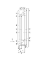
- FIG. 1 is a diagram illustrating a configuration of an image acquisition apparatus according to an embodiment of the present invention.
- FIG. 2 is a diagram conceptually illustrating the state of the observation object and the irradiation light in the vicinity thereof.
- FIG. 3 is a diagram schematically illustrating an example of the arrangement direction of the condensing points viewed from the optical axis direction of the objective lens.
- FIG. 4 is a diagram schematically showing another example of the arrangement direction of the condensing points viewed from the optical axis direction of the objective lens.
- FIG. 5 is a front view showing a light detection surface of the photodetector.
- FIG. 6 is a flowchart showing the operation of the image acquisition apparatus.
- FIG. 7 is a diagram conceptually showing how the reference height is set.
- FIG. 1 is a diagram illustrating a configuration of an image acquisition apparatus according to an embodiment of the present invention.
- FIG. 2 is a diagram conceptually illustrating the state of the observation object and the irradiation
- FIG. 8 is a diagram showing a first modification, and conceptually shows the state of the observation object and the irradiation light in the vicinity thereof.
- FIG. 9 is a diagram illustrating a state of a condensing point according to the fourth modification.
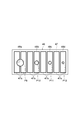
- FIG. 10 is a front view showing the light detection surface of the photodetector in the fourth modification.
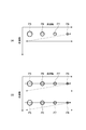
- FIG. 11 is a diagram conceptually showing how the condensing point is scanned as seen from the optical axis direction of the irradiation light.
- FIG. 12 is a diagram conceptually illustrating a state of scanning of the condensing point viewed from the optical axis direction of the irradiation light.
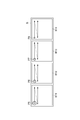
- FIG. 13 shows an image obtained by cutting out only a common area among the scanning areas of the condensing point.
- FIG. 14 shows an image obtained by cutting out only a common area among the scanning areas of the condensing point.
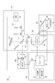
- FIG. 1 is a diagram showing a configuration of an image acquisition apparatus 1A according to an embodiment of the present invention.
- the image acquisition device 1A is a device for irradiating the observation object B with the irradiation light L1, and thereby observing the observation light (detected light) L2 generated in the observation object B.
- the image acquisition device 1A is, for example, a microscope device. Examples of the microscope apparatus include an upright microscope and an inverted microscope.
- the observation light L2 is, for example, fluorescence, phosphorescence, high frequency generated light (SHG), reflected light, transmitted light, scattered light, or the like.
- the image acquisition apparatus 1 ⁇ / b> A includes an irradiation light generation unit 10, a scanning unit 20, an irradiation optical unit 30, an observation unit 40, and a control unit 50.
- the irradiation light generation unit 10 generates irradiation light L1 that is irradiated onto the observation object B.
- the irradiation light generation unit 10 of this embodiment includes a light source 11, a beam expander 12, and a spatial light modulator (SLM) 13.
- SLM spatial light modulator
- the light source 11 outputs the irradiation light L0.
- the irradiation light L0 includes, for example, light having a wavelength to be irradiated on the observation object B.
- the light source 11 includes, for example, a pulsed light oscillation or continuous wave oscillation laser light source, an SLD light source, or an LED light source.
- the beam expander 12 includes, for example, a plurality of lenses 12a and 12b arranged side by side on the optical axis of the irradiation light L0, and adjusts the size of a cross section perpendicular to the optical axis of the irradiation light L0. .
- the lenses 12a and 12b may be convex lenses or concave lenses, or a combination thereof.
- the spatial light modulator 13 is optically coupled to the light source 11, and generates the irradiation light L 1 irradiated to the observation object B by modulating the irradiation light L 0 from the light source 11.
- the spatial light modulator 13 has a plurality of pixels arranged two-dimensionally, and modulates the intensity or phase of the irradiation light L0 output from the light source 11 for each of a plurality of pixel columns.
- the modulation pattern (hologram) presented to the spatial light modulator 13 is controlled by the control unit 50 described later.
- the spatial light modulator 13 may be a phase modulation type or an amplitude (intensity) modulation type.
- the spatial light modulator 13 may be either a reflection type or a transmission type. Further, a plurality of spatial light modulators 13 may be provided, and in that case, the irradiation light L0 is modulated a plurality of times.
- the scanning unit 20 is an example of a scanning unit in the present embodiment.
- the scanning unit 20 has an optical scanner 21 as a scanning optical system.
- the optical scanner 21 is optically coupled to the spatial light modulator 13 and receives the irradiation light L1 modulated by the spatial light modulator 13.
- the optical scanner 21 scans the irradiation position of the irradiation light L1 on the observation object B.
- the optical scanner 21 receives the observation light L2 generated at the condensing point of the observation object B. Thereby, the observation light L2 is descanned.
- the optical scanner 21 is controlled by a control unit 50 described later.
- the optical scanner 21 is configured by, for example, a galvanometer mirror, a resonant mirror, a MEMS mirror, a two-dimensional acoustooptic device (AOM), a polygon mirror, or the like.
- the optical scanner 21 can include an image transfer optical system such as a telecentric optical system.
- the scanning unit 20 may further include a mirror 22 in addition to the optical scanner 21.
- the mirror 22 bends the optical axis of the irradiation light L ⁇ b> 1 in order to optically couple the optical scanner 21 and the irradiation optical unit 30.
- the irradiation optical unit 30 irradiates the observation target B with the irradiation light L1 provided from the scanning unit 20 and outputs the observation light L2 from the observation target B to the observation unit 40.
- the irradiation optical unit 30 includes a stage 31, an objective lens 32, an objective lens moving mechanism 33, and a reflection mirror 34.
- a dichroic mirror may be used as the reflection mirror 34.
- the stage 31 is a member for supporting the observation object B (or a container such as a slide glass, a petri dish, a microplate, or a glass bottom dish that accommodates the observation object B).
- the stage 31 is made of glass, for example.
- the irradiation light L1 is irradiated from the front side of the stage 31, but the irradiation light L1 may pass through the stage 31 from the back side of the stage 31 and be irradiated to the observation object B.
- the stage 31 is movable in a surface direction that intersects (for example, intersects with) an optical axis of an objective lens 32 described later. Further, it may be movable in the optical axis direction of the objective lens 32.
- the objective lens 32 is a condensing optical system that is arranged to face the observation object B and forms a condensing point of the irradiation light L1 inside the observation object B.
- the objective lens 32 receives the observation light L2 generated at the condensing point of the observation object B and collimates the observation light L2.
- the objective lens for the irradiation light L1 and the objective lens for the observation light L2 may be provided separately.
- an objective lens having a high numerical aperture (NA) may be used for the irradiation light L ⁇ b> 1, and the light may be condensed locally by aberration correction by the spatial light modulator 13.
- the aberration amount on the surface and / or inside of the observation object B may be obtained by actual measurement or may be obtained by estimation by simulation or the like.
- an objective lens having a large pupil may be used for the observation light L2 so that more light can be extracted.
- the objective lens for the irradiation light L1 and the objective lens for the observation light L2 are arranged so as to sandwich the observation object B, and the transmitted light of the irradiation light L1 through the observation object B is acquired as the observation light L2. Also good.
- the objective lens moving mechanism 33 is a mechanism for moving the objective lens 32 in the optical axis direction of the irradiation light L1.
- the objective lens moving mechanism 33 is configured by, for example, a stepping motor or a piezo actuator.
- the reflection mirror 34 reflects the irradiation light L1 that has reached the irradiation optical unit 30 from the irradiation light generation unit 10 toward the objective lens 32. Further, the reflection mirror 34 reflects the observation light L2 from the observation object B toward the scanning unit 20.
- At least one telecentric optical system may be provided on the optical axes of the irradiation light L1 and the observation light L2.
- two telecentric optical systems 61 and 62 are shown in FIG.
- the telecentric optical systems 61 and 62 have a role of transferring the wavefront of the irradiation light L1 generated in the spatial light modulator 13 to the rear focal point of the objective lens 32.
- the telecentric optical systems 61 and 62 may be double-sided telecentric optical systems.
- the telecentric optical system 61 disposed between the spatial light modulator 13 and the optical scanner 21 is adjusted so as to form an image on the modulation surface of the spatial light modulator 13 and the scanning surface of the optical scanner 21.
- the telecentric optical system 62 disposed between the optical scanner 21 and the objective lens 32 is adjusted so as to form an image on the scanning surface of the optical scanner 21 and the pupil plane of the objective lens 32.
- the telecentric optical systems 61 and 62 are capable of transferring the wavefront of the irradiation light L1 generated by the spatial light modulator 13 to the rear focal point of the objective lens 32, and the image side telecentric optical system and the object side telecentric optics. It may be a system. Further, when the distance between the objective lens 32 and the spatial light modulator 13 is extremely short, the telecentric optical system can be omitted.
- the observation unit 40 includes a photodetector 41, a filter 42, and a condenser lens 43.
- the photodetector 41 is optically coupled to the objective lens 32 and the optical scanner 21, and receives the observation light L2 and detects the light intensity of the observation light L2.
- the photodetector 41 is optically coupled to the optical scanner 21 via the dichroic mirror 14 provided in the irradiation light generation unit 10.
- the dichroic mirror 14 is disposed at a position for receiving the irradiation light L1 modulated by the spatial light modulator 13 and the observation light L2 descanned by the optical scanner 21, and transmits at least a part of the irradiation light L1. Reflect at least partly.
- the photodetector 41 detects the light intensity of the observation light L2 and outputs a detection signal Sd.
- the photodetector 41 may be constituted by a multi-anode type photomultiplier tube (PMT) having a plurality of anodes, or a photodiode array in which a plurality of photodiodes are arranged in an array. Alternatively, it may be constituted by an avalanche photodiode array in which a plurality of avalanche photodiodes are arranged in an array.
- PMT multi-anode type photomultiplier tube
- the photodetector 41 may be an area image sensor having a plurality of pixels, such as a CCD image sensor, an EM-CCD image sensor, or a CMOS image sensor, or may be a line sensor.
- the multi-anode type PMT has a high multiplication factor and a light receiving surface larger than the others.
- the filter 42 is disposed on the optical axis between the dichroic mirror 14 and the photodetector 41.
- the filter 42 cuts the wavelength of the irradiation light L1 and the wavelength of fluorescence unnecessary for observation from the light incident on the photodetector 41.
- the condensing lens 43 is disposed immediately before the light detector 41 and condenses the observation light L2 toward the light detector 41. Note that the filter 42 may be disposed either before or after the condenser lens 43. Further, when the filter 42 is unnecessary, it may not be provided.
- the control unit 50 controls the irradiation light generation unit 10, the scanning unit 20, and the irradiation optical unit 30.
- the control unit 50 controls the light source 11, the spatial light modulator 13, and the optical scanner 21.
- the control unit 50 uses the objective lens moving mechanism 33 to control the position (height) of the objective lens 32 in the optical axis direction.
- the control unit 50 moves the stage 31 that supports the observation object B in a direction that intersects the optical axis direction.
- the control unit 50 includes an input device 51 such as a mouse and a keyboard, a display device 52 such as a display, and a computer 53.
- the computer 53 is an example of an image creating unit in the present embodiment.
- the computer 53 is a personal computer or a smart device, and includes an image processing circuit (image processing processor), a control circuit (control processor), and an internal memory.
- the computer 53 creates an image of the observation object B using the detection signal Sd from the light detector 41 and the light irradiation position information in the optical scanner 21.
- the created image is displayed on the display device 52.
- the computer 53 is an example of a control unit (controller) in the present embodiment.
- the computer 53 controls the modulation pattern (hologram) presented to the spatial light modulator 13 so that a desired condensing point is formed on the observation object B.
- the computer 53 controls the intensity or phase modulation amount of each of the plurality of pixels of the spatial light modulator 13 by controlling the modulation pattern presented to the spatial light modulator 13.
- the created image may be stored in the memory of the computer 53 or an external storage device.
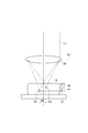
- FIG. 2 is a diagram conceptually showing the state of the irradiation light L1 in the observation object B and the vicinity thereof.
- the irradiation light L ⁇ b> 1 is collected by the objective lens 32 at a plurality of condensing points, that is, the first condensing point P ⁇ b> 1 and the second condensing point P ⁇ b> 2.
- a virtual line A1 in the figure is a reference line representing the reference height of the objective lens 32.
- the condensing points P1 and P2 have the following positional relationship. That is, the positions of the condensing points P1 and P2 in the optical axis direction of the objective lens 32 (in other words, the depth direction of the observation object B) are different from each other. This is because the depth d1 of the first condensing point P1 from the position where the optical axis of the objective lens 32 and the surface of the observation object B intersect with each other is different from the depth d2 of the second condensing point P2. Means that.
- the positions of the condensing points P1 and P2 in a certain direction perpendicular to the optical axis direction of the objective lens 32 are also different from each other.
- the condensing points P1 and P2 do not overlap each other and have a predetermined interval W.
- FIG. 3 is a diagram schematically showing an example of the arrangement direction of the condensing points P1 and P2 when viewed from the optical axis direction of the objective lens 32.
- FIG. 3A shows the scanning direction A2 of the condensing points P1 and P2
- FIG. 3B shows the scanning by the optical scanner 21 of the condensing points P1 and P2 viewed from the optical axis direction of the irradiation light L1.
- the state of is shown.
- the condensing points P1 and P2 are arranged along the scanning direction A2 when viewed from the optical axis direction of the irradiation light L1. Further, as shown in FIG.
- the scanning by the optical scanner 21 has a high-speed axis and a low-speed axis, and the condensing points P1 and P2 move along the high-speed axis and then move along the low-speed axis.
- the operation of shifting in the direction and moving along the high-speed axis again is repeated.
- the arrangement direction of the condensing points P1 and P2 viewed from the optical axis direction of the irradiation light L1 is along the high-speed axis (that is, the scanning direction).
- the optical scanner 21 may scan the condensing points P1 and P2 so that the condensing points P1 and P2 move in the low-speed axis direction while moving along the high-speed axis. Further, not only line scanning but also tiling scanning may be used.
- FIG. 4 is a diagram schematically showing another example of the arrangement direction of the condensing points P1 and P2 when viewed from the optical axis direction of the objective lens 32.
- 4A shows the scanning direction A3 of the condensing points P1 and P2
- FIG. 4B shows scanning of the condensing points P1 and P2 as viewed from the optical axis direction of the irradiation light L1 by the optical scanner 21.
- the state of is shown.
- the focal points P1 and P2 are aligned along the direction A4 (first direction) intersecting the scanning direction A3 when viewed from the optical axis direction of the irradiation light L1. It is out. Further, as shown in FIG.
- the arrangement direction A4 of the condensing points P1 and P2 viewed from the optical axis direction of the irradiation light L1 is a low-speed axis (that is, an axis that intersects the scanning direction). It is along.
- the direction A4 is, for example, orthogonal to the scanning direction A3 or inclined with respect to the scanning direction A3.
- the condensing points P1 and P2 formed by the positional relationship as described above are realized by the computer 53 that controls the modulation pattern presented to the spatial light modulator 13 and the objective lens 32.
- the computer 53 controls the modulation pattern so that the condensing points P1 and P2 are formed in the observation object B.
- the condensing points P1 and P2 are formed by the objective lens 32 that has received the modulated irradiation light L1.
- FIG. 5 is a front view showing the light detection surface 44 of the photodetector 41 of the present embodiment.
- the light detection surface 44 has a point image P3 of observation light (first observation light) generated from the condensing point P1 and observation light (second light) generated from the condensing point P2.
- a point image P4 of (observation light) is formed.
- the light detector 41 detects the first and second observation lights by detecting the light intensity of each of the point images P3 and P4.
- the distance of a condensing point and the objective lens 32 becomes so long that the depth of the condensing point in the observation target object B is deep, the light diameter of the observation light which reaches the photodetector 41 becomes large.
- the point image P3 of the observation light from the condensing point P1 is the observation light from the condensing point P2. It is shown larger than the point image P4.
- the photodetector 41 includes a plurality of photodetectors 44a.
- the light detection unit 44a corresponds to each anode of the multi-anode PMT.
- the light detection unit 44a corresponds to one pixel or a pixel group.
- the photodetector 41 is a photodiode array (line sensor)
- the light detection unit 44a corresponds to each photodiode.
- the photodetector 41 has a first detection area 45a for detecting the point image P3 and a second detection area 45b for detecting the point image P4.
- the detection areas 45a and 45b are areas independent from each other, and each include one or a plurality of light detection units 44a.
- the sizes of the point images P3 and P4 formed on the light detection surface 44 that is a plane are also different from each other. That is, the point images P3 and P4 increase as the depths d1 and d2 of the condensing points P1 and P2 increase.
- the focal position of the objective lens 32 in the optical axis direction of the objective lens 32 and the focal points P1 and P2 Since the distances are different from each other, the sizes of the point images P3 and P4 formed on the light detection surface 44 which is a plane are also different from each other. That is, the point images P3 and P4 increase as the distance between the focal position of the objective lens 32 in the optical axis direction of the objective lens 32 and the focal points P1 and P2 increases.
- a plurality of light detection units 44a may be set as detection areas.
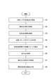
- FIG. 6 is a flowchart showing the operation of the image acquisition apparatus 1A described above. The image acquisition method according to the present embodiment will be described with reference to FIG.
- step S1 the reference height of the objective lens 32 is set (step S1).
- the distance between the objective lens 32 and the observation object B is adjusted by the objective lens moving mechanism 33 or the stage 31, and the reference height is set.
- FIG. 7 is a diagram conceptually showing how the reference height Z0 is set.
- the height of the objective lens 32 may be adjusted so that the focal position of the objective lens 32 matches the surface of the observation object B, and the height may be set as the reference height Z0.
- the stage 31 may be moved in the optical axis direction of the objective lens 32 so that the focal position of the objective lens 32 matches the surface of the observation object B.
- the computer 53 stores this reference height Z0.
- the depths d1 and d2 of the condensing points P1 and P2 shown in FIG. 2 are set (step S2).
- the observer sets the depth (the depths d ⁇ b> 1 and d ⁇ b> 2 in FIG. 2) inside the observation object B to be imaged via the input device 51.
- the depth inside the observation object B may be an actual distance or an optical distance.
- the depth d1, d2 may be calculated.
- the optical distance as d may be considered that the amount of movement in the optical axis direction of the stage 31 and / or the objective lens 32 is n a ⁇ d / n b.
- the interval W between the condensing points P1 and P2 shown in FIG. 2 is set (step S3).
- the irradiation light L1 modulated by the spatial light modulator 13 is condensed by the objective lens 32, thereby forming a plurality of condensing points P1 and P2 inside the observation object B. If the interval W between the plurality of condensing points P1 and P2 is narrow, the point images P3 and P4 overlap in the photodetector 41 and crosstalk occurs. Therefore, an appropriate interval W that does not overlap the point images P3 and P4 is set. It is desirable to set. In particular, as shown in FIG.
- the depth of the condensing point is deeper to prevent crosstalk. It is better to increase the interval W. Further, for example, based on parameters such as the numerical aperture (NA) of the objective lens 32, the refractive index of the medium between the objective lens 32 and the observation object B, the refractive index of the observation object B, and the wavelength of the irradiation light L1.
- the interval W may be set.
- a modulation pattern (hologram) is created (step S4).
- a computer generated hologram (CGH) to be presented to the spatial light modulator 13 is created based on the interval W and the depths d1 and d2 of the condensing points P1 and P2 set in the steps S2 and S3. .
- This step S4 is performed by the computer 53, for example.
- the CGH corresponding to the depths d1 and d2 and the interval W may be calculated in advance and stored as a table in storage means inside the computer 53, and an appropriate CGH may be selected from the table.
- step S4 the CGH created in step S4, that is, the modulation pattern in which the condensing points P1 and P2 are formed in the observation object B is presented to the spatial light modulator 13 (pattern presentation step S5).
- the irradiation light L0 output from the light source 11 is modulated by the spatial light modulator 13, and the modulated irradiation light L1 is collected by the objective lens 32 to be collected at the depths d1 and d2 of the observation object B.
- Light spots P1 and P2 are formed (focusing point forming step S6).
- steps S5 and S6 the distance between the objective lens 32 and the observation object B is adjusted so that the condensing points P1 and P2 are formed at the depths d1 and d2 inside the observation object B.
- CGH is presented to the spatial light modulator 13, whereby the irradiation light L0 output from the light source 11 is modulated, and the modulated irradiation light L1 is condensed by the objective lens 32, and the observation object B
- a first condensing point P1 is formed at a position of an internal depth d1
- a second condensing point P2 is formed at a position of a depth d2 with a spacing W.
- CGH may be presented to the spatial light modulator 13 and the modulated irradiation light L1 may be condensed by the objective lens 32.
- scanning of the condensing points P1 and P2 and light detection are performed (light detection step S7).
- this light detection step S7 the observation light generated from the condensing points P1 and P2 while scanning the positions of the condensing points P1 and P2 inside the observation object B in the scanning direction intersecting the optical axis of the irradiation light L1. L2 is detected.
- the positions of the point images P3 and P4 of the observation light L2 in the photodetector 41 are fixed and detected while moving the condensing points P1 and P2. be able to. From the photodetector 41, detection signals Sd corresponding to the respective point images P3 and P4 are output to the computer 53.
- an image of the observation object B is created (image creation step S8).
- image creation step S8 using the detection signal Sd (light intensity information) obtained in the light detection step S7 and the optical scanning position information (planar position information of the condensing points P1 and P2) by the optical scanner 21, An image of the observation object B is created by the computer 53.
- this image creation step S8 may be performed in parallel with the above-described light detection step S7.
- the characteristics of the acquired image differ depending on the arrangement direction of the condensing points P1 and P2 with respect to the scanning direction.
- the condensing point P1 reaches the lower region of the trace where the condensing point P2 has moved with a time difference.
- the influence of the surroundings by the condensing point P2 can be known from the image of the condensing point P1.
- a three-dimensional composite image may be created by combining the image obtained by the condensing point P1 and the image obtained by the condensing point P2.
- the depth is obtained by scanning the condensing point P1 without moving the objective lens 32.
- An image having a depth d2 can be obtained, and an image having a depth d2 can be obtained by scanning the condensing point P2.
- the modulation pattern is presented to the spatial light modulator 13, thereby condensing the irradiation light L1 in the optical axis direction (that is, the depth direction of the observation object B).
- the condensing points P1 and P2 having different positions can be formed simultaneously and easily.
- the condensing points P1 and P2 are scanned, and the observation light L2 generated at the respective condensing points P1 and P2 forms point images P3 and P4 in the photodetector 41, and each point image P3. , P4 is detected by the photodetector 41.
- the photodetector 41 has a detection area 45a for detecting the light intensity of the observation light L2 in the point image P3 and a detection area 45b for detecting the light intensity of the observation light L2 in the point image P4.
- the two observation lights L2 having different light emission positions can be detected simultaneously.
- An example of the optical scanner is an optical scanner using a resonant mirror.
- the scanning speed of the resonant mirror is about 10 kHz, and the scanning time of the high-speed axis is 100 ⁇ sec.
- the objective lens or the stage needs to be moved in the optical axis direction, and the sweep must be performed at different depths in the optical axis direction. For this reason, it takes at least 100 ⁇ sec or more to sweep regions of different depths.
- other optical scanners such as an optical scanner using a galvanometer mirror also require the same time because the objective lens or the stage needs to be moved in the optical axis direction in order to sweep regions of different depths. .
- the spatial light modulator 13 can generate a plurality of condensing points P1 and P2 having different positions in the optical axis direction, for example, along the high-speed axis. Information of portions having different depths can be obtained with a time difference. Therefore, since information on portions having different depths can be obtained at the same time, it is easy to compare portions having different depths.
- condensing points P1 and P2 by forming a plurality of condensing points P1 and P2 using the modulation pattern presented in the spatial light modulator 13, it can be easily placed at a desired position in a direction perpendicular or parallel to the optical axis direction of the irradiation light L1. Condensation can be performed, and the number of condensing points, position, intensity, and the like can be easily changed.
- the condensing points P1 and P2 may be arranged along the scanning direction A2 when viewed from the optical axis direction of the irradiation light L1.
- an effect caused by the condensing point P2 located on the front side in the scanning direction A2 at a depth different from the condensing point P2 is observed from the condensing point P1 located on the rear side in the scanning direction A2. It can be known almost simultaneously by detecting the light L2.
- the photodetector 41 may include a multi-anode photomultiplier having a plurality of anodes, or may include an area image sensor having a plurality of pixels. By either of these, the observation light L2 can be detected with high accuracy in each of the point images P3 and P4.
- the image acquisition apparatus of the present embodiment can be used particularly for a multiphoton excitation fluorescence microscope.
- a liquid crystal type spatial light modulator has polarization dependency. Since fluorescence is generally non-polarized, in order to perform phase control using a liquid crystal type spatial light modulator, two spatial light modulators are used and phase modulation is performed in two polarization directions. It is desirable to do.
- the reflectance of a liquid crystal type spatial light modulator is generally about 90%, and the reflectance is 81% when two spatial light modulators are used. Therefore, there is a possibility that weak fluorescence is further weakened.
- the deformable mirror when a deformable mirror is used instead of the spatial light modulator, the deformable mirror has no polarization dependency.
- a structure in which one mirror is pushed from the back by a plurality of actuators is inferior in terms of phase expression ability, and a structure in which mirrors and actuators are arranged in a matrix form is inferior in reflectance.
- the multiphoton excitation fluorescence microscope fluorescence is generated particularly at a position where the photon density is high near the focal point. If excitation light can be condensed without the influence of aberration, it is considered that the resulting fluorescence is only the fluorescence near the focal point. Therefore, if only the aberration of the excitation light is corrected and all the generated fluorescence is observed, the influence of the aberration on the fluorescent side can be almost ignored. Therefore, since it is not necessary to apply a spatial light modulator to the observation light, the above problem does not occur, and the multi-photon excitation fluorescence microscope can suitably use the spatial light modulator.
- FIG. 8 is a diagram showing a first modification of the embodiment, and conceptually shows the state of the observation object B and the irradiation light L1 in the vicinity thereof.
- one condensing point for example, a condensing point P ⁇ b> 2
- the distance between the objective lens 32 and the observation object B is shorter than that in FIG.
- a virtual line A1 in the figure represents the reference height of the objective lens 32.
- the depth d2 of the condensing point P2 may be realized by adjusting the distance between the objective lens 32 and the observation object B.
- the spatial light modulator 13 may simply present a modulation pattern in which the focal point P2 is formed at the focal length of the objective lens 32, and realizes the depth d2 of the focal point P2 ( In other words, a modulation pattern (for changing the distance between the focal point P2 and the objective lens 32 from the focal length) becomes unnecessary.
- the computer 53 uses the condensing point based on the distance d3 between the condensing point P1 and the condensing point P2 in the optical axis direction of the irradiation light L1. It is preferable to calculate (or select) a modulation pattern for realizing the depth d1 of P1. Further, the user may directly input the position of the objective lens 32 with respect to the reference height Z0 into the computer 53.
- the condensing points P1 and P2 are scanned by the optical scanner 21, but the condensing points P1 and P2 are moved by moving the stage 31 in a plane direction intersecting the optical axis direction. You may scan.
- the scanning unit of the above embodiment may include the stage 31 instead of or together with the optical scanner 21. Even with such a configuration, the condensing points P1 and P2 can be suitably scanned.
- the condensing points P1 and P2 are scanned by the optical scanner 21, but the condensing points P1 and P2 are scanned in the modulation pattern presented to the spatial light modulator 13. These patterns (optical scanning holograms) may be included (superimposed). In this case, since the scanning unit in the above embodiment is not necessary, the number of components of the image acquisition device 1A can be reduced, which can contribute to downsizing.
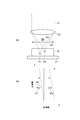
- FIG. 9 is a diagram illustrating a state of the light condensing point according to the fourth modification of the embodiment.
- this modification four condensing points P5 to P8 are formed inside the observation object B. Since the condensing points P5 to P8 are different in position in the optical axis direction of the irradiation light L1, their depths d5 to d8 from the surface of the observation object B are different from each other. Further, when viewed from the optical axis direction of the irradiation light L1, these condensing points P5 to P8 are arranged along the scanning direction (arrows A5 to A8 in the figure) at a certain interval.
- the condensing points P5 to P8 are arranged in the scanning direction when viewed from the optical axis direction of the irradiation light L1, the light is collected at both ends of the observation object B in the scanning direction. Regions (B1, B2 in the figure) where the light spot does not pass are generated. Therefore, for example, it is preferable to create an image limited to the region B3 through which all the condensing points P5 to P8 pass. Specifically, for example, it is preferable to detect observation lights from the condensing points P5 to P8 to acquire images having different depths, and to extract an image of a region having a common scanning range from these images.
- FIG. 10 is a front view showing the light detection surface 47 of the light detector 46 in this modification.
- point images P9 to P12 are formed by the observation light generated from the respective condensing points P5 to P8.
- the photodetector 46 detects a plurality of observation lights by detecting the light intensity of each of the point images P9 to P12.
- the light diameter of the observation light which reaches the photodetector 46 becomes large.
- the light spots are formed at deep positions in the order of the condensing points P5 to P8. Therefore, in FIG. 10, the point image P9 of the observation light from the condensing point P5 is the largest, and the point of the observation light from the condensing point P8 is large.
- the image P12 is the smallest.
- the light detector 46 includes a plurality of light detection units 47a, and has detection regions 48a to 48d for detecting point images P9 to P12, respectively.
- the detection areas 48a to 48d are areas independent from each other, and each include one or a plurality of light detection units 47a.
- FIG. 11 and FIG. 12 are diagrams conceptually showing how the condensing points P5 to P8 are scanned when viewed from the optical axis direction of the irradiation light L1.
- the condensing points P5 to P8 may be arranged in a line along the high-speed axis.
- FIG. 11B a plurality of condensing points P5 to P8 are formed, the observation object B is divided into a plurality of regions, and each region is scanned by a group of condensing points P5 to P8. May be.
- the observation object B may be divided into a plurality of regions B11 to B14, and each region may be scanned by one condensing point P5, P6, P7 or P8.
- the irradiation light intensity per one condensing point is (E / N) ⁇ ⁇ , where E is the total amount of irradiation light L1, N is the number of condensing points, and ⁇ is the efficiency of the spatial light modulator.
- the efficiency ⁇ of the spatial light modulator is the light utilization efficiency (the ratio of the amount of light used for phase modulation of the incident light amount) and the diffraction efficiency (the ratio of the amount of light that can be diffracted to a desired position.
- the irradiation light intensity per one condensing point is also changed.
- the observation light intensity also changes, which may cause block noise in the reconstructed image.
- an optical system and a measurement system for measuring the intensity change and intensity variation of each point image of the observation light L2 may be provided and fed back to the light output intensity of the light source 11.
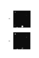
- FIG. 13 and 14 show images obtained by cutting out only a common area (area B3 in FIG. 9) among the scanning areas of the condensing points P5 to P8.
- FIG. 13 (a) shows an image obtained from the condensing point P8
- FIG. 13 (b) shows an image obtained from the condensing point P7
- FIG. 14 (a) is obtained from the condensing point P6.
- An image is shown
- FIG.14 (b) shows the image obtained from the condensing point P5.
- there is no fluorescent bead having a diameter of 3 ⁇ m that exists over three of these four images it is considered that sufficient resolution in the depth direction can be secured.
- SYMBOLS 1A Image acquisition device, 10 ... Irradiation light generation unit, 11 ... Light source, 12 ... Beam expander, 13 ... Spatial light modulator, 14 ... Dichroic mirror, 20 ... Scanning unit, 21 ... Optical scanner, 22 ... Mirror, 30 Irradiating optical unit 31 ... stage 32 ... objective lens 33 ... objective lens moving mechanism 34 ... reflecting mirror 40 ... observation unit 41 ... photodetector 42 ... filter 43 ... condensing lens 44 ... light Detection surface, 44a ... light detection unit, 45a ... first detection region, 45b ... second detection region, 50 ... control unit, 51 ... input device, 52 ... display device, 53 ...
Landscapes
- Physics & Mathematics (AREA)
- Chemical & Material Sciences (AREA)
- General Physics & Mathematics (AREA)
- Analytical Chemistry (AREA)
- Optics & Photonics (AREA)
- Health & Medical Sciences (AREA)
- Nonlinear Science (AREA)
- Engineering & Computer Science (AREA)
- Multimedia (AREA)
- Biochemistry (AREA)
- Nuclear Medicine, Radiotherapy & Molecular Imaging (AREA)
- Life Sciences & Earth Sciences (AREA)
- General Health & Medical Sciences (AREA)
- Immunology (AREA)
- Pathology (AREA)
- Crystallography & Structural Chemistry (AREA)
- Mathematical Physics (AREA)
- Computer Vision & Pattern Recognition (AREA)
- Spectroscopy & Molecular Physics (AREA)
- Microscoopes, Condenser (AREA)
- Investigating, Analyzing Materials By Fluorescence Or Luminescence (AREA)
Abstract
照射光を変調する空間光変調器と、観察対象物に第1の集光点および第2の集光点が形成されるように変調パターンを制御する制御部と、前記照射光を集光する集光光学系と、前記集光光学系の光軸と交差する走査方向に前記第1及び第2の集光点の位置を走査する走査部と、前記第1の集光点から生じた第1の観察光、及び前記第2の集光点から生じた第2の観察光を検出する光検出器と、を備え、前記光検出器は、前記第1の観察光を検出するための第1の検出領域と、前記第2の観察光を検出するための第2の検出領域と、を有し、前記光軸の方向における前記第1及び第2の集光点の位置が互いに異なる、画像取得装置。
Description
本発明の一側面は、画像取得装置および画像取得方法に関する。
非特許文献1は、空間光変調器(Spatial Light Modulator;SLM)を用いた多光子吸収顕微鏡を開示する。この顕微鏡は、SLMを用いて、複数の励起光スポットを形成して走査することにより、観察対象物内の蛍光画像を高速に且つ鮮明に取得することを企図している。
Wan Qin, Yonghong Shao, Honghai Liu, Xiang Peng, Hanben Niu, and Bruce Gao, "Addressable discrete-line-scanning multiphoton microscopy based on a spatial light modulator", OPTICS LETTERS, Vol. 37, No. 5, pp.827-829, March 1, 2012
近年、観察対象物に照射される励起光や照明光といった光を、SLMを用いて変調する技術が研究されている。このような技術によれば、観察対象物に対して様々な照射光、例えば平坦な強度分布を有する光や複数の位置(スポット)に同時に照射される光などを実現することができる。
このような技術において複数の位置に同時に光を照射する場合、照射光の光軸方向に対して垂直な面内において集光位置が異なる複数のスポット光を照射するものは存在するが(例えば非特許文献1を参照)、光軸方向と平行な方向、すなわち観察対象物の深さ方向において集光位置が異なる複数のスポット光を同時に照射する技術はこれまで何ら開示されていない。集光位置を深さ方向に異ならせることができれば、深さが異なる複数の箇所を同時に観察することが可能となるので、観察対象物が厚い場合などにおいて観察時間を短縮でき、また深さが異なる複数の箇所の同時刻における状況を取得できる等の顕著な利点がある。
本発明の一側面は、観察対象物の深さ方向において集光位置が互いに異なる複数の光を同時に照射することができる画像取得装置および画像取得方法を提供することを目的とする。
本発明の一実施形態による画像取得装置は、観察対象物の画像を取得する装置であって、光源から出力された照射光を変調する空間光変調器と、観察対象物において第1の集光点および第2の集光点が形成されるように、空間光変調器に呈示される変調パターンを制御する制御部と、観察対象物中に第1の集光点および第2の集光点を形成するために、変調された照射光を集光する集光光学系と、集光光学系の光軸と交差する走査方向に、観察対象物中の第1の集光点および第2の集光点の位置を走査する走査部と、第1の集光点から生じた第1の観察光、及び第2の集光点から生じた第2の観察光を検出する光検出器と、光検出器からの検出信号を用いて観察対象物の画像を作成する画像作成部とを備える。光検出器は、第1の観察光を検出するための第1の検出領域と、第2の観察光を検出するための第2の検出領域とを有する。集光光学系の光軸の方向における第1の集光点および第2の集光点の位置は互いに異なる。
また、本発明の別の実施形態による画像取得装置は、観察対象物の画像を取得する装置であって、光源から出力された照射光を変調する空間光変調器と、観察対象物において第1の集光点および第2の集光点が形成されるように、空間光変調器に呈示される変調パターンを制御する制御部と、観察対象物中に第1の集光点および第2の集光点を形成するために、変調された照射光を集光する集光光学系と、第1の集光点から生じた第1の観察光、及び第2の集光点から生じた第2の観察光を検出する光検出器と、光検出器からの検出信号を用いて観察対象物の画像を作成する画像作成部とを備える。変調パターンは、集光光学系の光軸と交差する走査方向に第1の集光点および第2の集光点を走査するためのパターンを含む。光検出器は、第1の観察光を検出するための第1の検出領域と、第2の観察光を検出するための第2の検出領域とを有する。集光光学系の光軸の方向における第1の集光点および第2の集光点の位置は互いに異なる。
また、本発明の一実施形態による画像取得方法は、観察対象物の画像を取得する方法であって、観察対象物において第1の集光点および第2の集光点を形成するための変調パターンを空間光変調器に呈示するステップと、観察対象物中に第1の集光点および第2の集光点を形成するために、光源から出力された照射光を空間光変調器において変調し、変調された照射光を集光光学系により集光するステップと、集光光学系の光軸と交差する走査方向に、観察対象物中の第1の集光点および第2の集光点の位置を走査しつつ、第1の集光点から生じた第1の観察光、及び第2の集光点から生じた第2の観察光を検出するステップと、光検出ステップにより得られた検出信号を用いて観察対象物の画像を作成するステップとを含む。光検出ステップでは、第1の観察光を検出するための第1の検出領域と、第2の観察光を検出するための第2の検出領域とを有する光検出器を用いる。集光光学系の光軸の方向における第1の集光点および第2の集光点の位置は互いに異なる。
これらの画像取得装置および画像取得方法では、変調パターンが空間光変調器に呈示されることにより、光軸の方向(すなわち観察対象物の深さ方向)における集光位置が互いに異なる第1の集光点および第2の集光点を同時に且つ容易に形成することができる。そして、第1の集光点および第2の集光点が走査(スキャン)されるとともに、各集光点において生じた第1の観察光および第2の観察光が光検出器によって検出される。光検出器は、第1の観察光を検出するための第1の検出領域と、第2の観察光を検出するための第2の検出領域とを有するので、発光位置が互いに異なる第1の観察光および第2の観察光を同時に検出することができる。このように、上記の各画像取得装置および画像取得方法によれば、観察対象物の深さ方向において集光位置が互いに異なる複数の光を同時に照射することができ、更に、深さ方向において発光位置が互いに異なる複数の観察光を同時に検出することができる。従って、観察対象物が厚い場合などにおいて観察時間を短縮でき、また深さが異なる複数の箇所の同時刻における状況を容易に取得できる。
上記の画像取得装置および画像取得方法において、光軸の方向から見て第1の集光点および第2の集光点は走査方向に並んでいてもよい。これにより、例えば、走査方向前側に位置する集光点により該集光点とは異なる深さにて生じる影響を、走査方向後側に位置する集光点から生じる観察光を検出することによって同時に知ることができる。
或いは、上記の画像取得装置および画像取得方法において、光軸の方向から見て第1の集光点および第2の集光点は走査方向と交差する第1の方向に並んでいてもよい。この場合、第1の方向は、走査方向と直交してもよく、或いは走査方向に対して傾斜してもよい。これにより、例えば、光軸方向に直交する面内の異なる位置の異なる深さによって生じる現象を同時に観察することができる。
上記の画像取得装置において、走査部は、変調された照射光を受ける光スキャナを含んでもよく、或いは、観察対象物を保持しつつ走査方向に観察対象物を移動させるステージを含んでもよい。同様に、上記の画像取得方法の光検出ステップでは、変調された照射光を受ける光スキャナを用いて第1の集光点および第2の集光点の走査を行ってもよく、観察対象物を保持しつつ走査方向に観察対象物を移動させるステージを用いて第1の集光点および第2の集光点の走査を行ってもよく、或いは、第1の集光点および第2の集光点を走査するためのパターンを変調パターンに重畳させてもよい。これらの何れかによって、第1の集光点および第2の集光点の位置を走査することができる。
上記の画像取得装置および画像取得方法において、光検出器は、複数のアノードを有するマルチアノード光電子増倍管を含んでもよく、或いは、複数の画素を有するエリアイメージセンサを含んでもよい。これらの何れかによって、第1および第2の観察光を精度良く検出することができる。
本発明の一側面による画像取得装置および画像取得方法によれば、観察対象物の深さ方向において集光位置が互いに異なる複数の光を同時に照射することができる。
以下、添付図面を参照しながら本発明の一側面による画像取得装置および画像取得方法の実施の形態を詳細に説明する。なお、図面の説明において同一の要素には同一の符号を付し、重複する説明を省略する。
図1は、本発明の一実施形態に係る画像取得装置1Aの構成を示す図である。画像取得装置1Aは、観察対象物Bに照射光L1を照射し、これにより観察対象物Bにおいて生じる観察光(被検出光)L2を観察するための装置である。画像取得装置1Aは、例えば顕微鏡装置である。顕微鏡装置としては、例えば、正立型顕微鏡あるいは倒立型顕微鏡が挙げられる。観察光L2は、例えば蛍光、りん光、高周波発生光(SHG)、反射光、透過光、散乱光などである。図1に示されるように、画像取得装置1Aは、照射光生成ユニット10、走査ユニット20、照射光学ユニット30、観察ユニット40、及び制御ユニット50を備えている。
照射光生成ユニット10は、観察対象物Bに照射される照射光L1を生成する。本実施形態の照射光生成ユニット10は、光源11、ビームエキスパンダ12、及び空間光変調器(Spatial Light Modulator:SLM)13を有する。
光源11は、照射光L0を出力する。照射光L0は、例えば観察対象物Bに照射すべき波長の光を含む。光源11は、例えばパルス光発振や連続波発振のレーザ光源、SLD光源、或いはLED光源等を含んで構成される。ビームエキスパンダ12は、例えば照射光L0の光軸上に並んで配置された複数のレンズ12a,12bを含んで構成され、照射光L0の光軸に対して垂直な断面の大きさを調整する。なお、レンズ12a,12bは、凸レンズでも凹レンズでもよく、それらを組わせてもよい。
空間光変調器13は、光源11と光学的に結合されており、光源11からの照射光L0を変調することにより、観察対象物Bへ照射される照射光L1を生成する。空間光変調器13は、二次元に配列された複数の画素を有し、光源11から出力された照射光L0の強度或いは位相を複数の画素列毎に変調する。空間光変調器13に呈示される変調パターン(ホログラム)は、後述する制御ユニット50によって制御される。空間光変調器13は、位相変調型でも良いし、振幅(強度)変調型でも良い。また、空間光変調器13は、反射型及び透過型の何れであってもよい。また、空間光変調器13は複数枚設けられてもよく、その場合、照射光L0は複数回にわたって変調される。
走査ユニット20は、本実施形態における走査部の例である。走査ユニット20は、走査光学系としての光スキャナ21を有する。光スキャナ21は、空間光変調器13と光学的に結合されており、空間光変調器13によって変調された照射光L1を受ける。また、光スキャナ21は、観察対象物Bにおける照射光L1の照射位置を走査する。さらに、光スキャナ21は、観察対象物Bの集光点において発生する観察光L2を受ける。これにより、観察光L2はデスキャンされる。光スキャナ21は、後述する制御ユニット50によって制御される。光スキャナ21は、例えばガルバノミラー、共振ミラー、MEMSミラー、2次元音響光学素子(AOM)若しくはポリゴンミラー等によって構成される。なお、光スキャナ21が二軸スキャナである場合、光スキャナ21はテレセントリック光学系などの像転送光学系を含むことができる。
なお、走査ユニット20は、光スキャナ21に加えて、ミラー22を更に有してもよい。ミラー22は、光スキャナ21と照射光学ユニット30とを光学的に結合させるために、照射光L1の光軸を屈曲させる。
照射光学ユニット30は、走査ユニット20から提供される照射光L1を観察対象物Bに照射するとともに、観察対象物Bからの観察光L2を観察ユニット40へ出力する。照射光学ユニット30は、ステージ31、対物レンズ32、対物レンズ移動機構33、及び反射ミラー34を有する。なお、反射ミラー34としてダイクロイックミラーを用いてもよい。
ステージ31は、観察対象物B(若しくは観察対象物Bを収容するスライドガラスやシャーレ、マイクロプレート、ガラスボトムディッシュなどの容器)を支持するための部材である。ステージ31は、例えばガラスからなる。図1に示された例では照射光L1はステージ31の表面側から照射されるが、照射光L1はステージ31の裏面側からステージ31を透過して観察対象物Bに照射されてもよい。ステージ31は、後述する対物レンズ32の光軸に対して交差(たとえば直交)する面方向に移動可能である。また、対物レンズ32の光軸方向に移動可能であってもよい。
対物レンズ32は、観察対象物Bと対向して配置され、観察対象物Bの内部に照射光L1の集光点を形成する集光光学系である。また、対物レンズ32は、観察対象物Bの該集光点において発生した観察光L2を受け、観察光L2を平行化する。照射光L1のための対物レンズと観察光L2のための対物レンズとは別個に設けられてもよい。例えば、照射光L1のために開口数(NA)が高い対物レンズを用い、空間光変調器13による収差補正により局所的に集光させてもよい。この場合、観察対象物Bの表面及び/又は内部の収差量は、実際に測定しても求められてもよいし、シミュレーション等により推定して求められてもよい。また、観察光L2のために瞳の大きな対物レンズを用い、より多くの光を取り出せるようにしてもよい。照射光L1のための対物レンズと観察光L2のための対物レンズとを観察対象物Bを挟むように配置して、照射光L1の観察対象物Bにおける透過光を観察光L2として取得してもよい。
対物レンズ移動機構33は、対物レンズ32を照射光L1の光軸方向に移動させるための機構である。対物レンズ移動機構33は、例えばステッピングモータ若しくはピエゾアクチュエータ等によって構成される。
反射ミラー34は、照射光生成ユニット10から照射光学ユニット30に到達した照射光L1を、対物レンズ32へ向けて反射する。また、反射ミラー34は、観察対象物Bからの観察光L2を走査ユニット20に向けて反射する。
対物レンズ32と空間光変調器13との距離が長い場合には、照射光L1及び観察光L2の光軸上に少なくとも一つのテレセントリック光学系が設けられてもよい。一例として、図1には2つのテレセントリック光学系61及び62が示されている。テレセントリック光学系61及び62は、空間光変調器13において生成された照射光L1の波面を対物レンズ32の後側焦点へ転送する役割を有する。テレセントリック光学系61及び62は、両側テレセントリック光学系であってもよい。この場合、空間光変調器13と光スキャナ21との間に配置されるテレセントリック光学系61は、空間光変調器13の変調面と光スキャナ21の走査面とに結像するように調整される。また、光スキャナ21と対物レンズ32との間に配置されるテレセントリック光学系62は、光スキャナ21の走査面と対物レンズ32の瞳面とに結像するように調整される。なお、テレセントリック光学系61,62は、空間光変調器13にて生成された照射光L1の波面を対物レンズ32の後側焦点へ転送可能であれば、像側テレセントリック光学系や物体側テレセントリック光学系であってもよい。また、対物レンズ32と空間光変調器13との距離が極めて近い場合には、テレセントリック光学系を省くことも可能である。
観察ユニット40は、光検出器41、フィルタ42、及び集光レンズ43を有する。光検出器41は、対物レンズ32及び光スキャナ21に光学的に結合されており、観察光L2を受けて、観察光L2の光強度を検出する。光検出器41は、照射光生成ユニット10に設けられたダイクロイックミラー14を介して光スキャナ21と光学的に結合される。ダイクロイックミラー14は、空間光変調器13によって変調された照射光L1及び光スキャナ21によってデスキャンされた観察光L2を受ける位置に配置され、照射光L1の少なくとも一部を透過し、観察光L2の少なくとも一部を反射する。光検出器41は、観察光L2の光強度を検出し、検出信号Sdを出力する。光検出器41は、複数のアノードを有するマルチアノード型の光電子増倍管(Photomultiplier Tube;PMT)によって構成されてもよく、または、複数のフォトダイオードがアレイ状に並んで構成されるフォトダイオードアレイ、若しくは、複数のアバランシェフォトダイオードがアレイ状に並んで構成されるアバランシェフォトダイオードアレイによって構成されてもよい。或いは、光検出器41は、CCDイメージセンサ、EM-CCDイメージセンサ、若しくはCMOSイメージセンサといった、複数の画素を有するエリアイメージセンサであってもよく、また、ラインセンサであってもよい。特に、マルチアノード型のPMTは、増倍率が高く且つ受光面が他よりも大きい。
フィルタ42は、ダイクロイックミラー14と光検出器41との間の光軸上に配置される。フィルタ42は、光検出器41に入射する光から、照射光L1の波長、及び観察に不要な蛍光等の波長をカットする。集光レンズ43は、光検出器41との直前に配置され、観察光L2を光検出器41に向けて集光する。なお、フィルタ42は、集光レンズ43の前段、後段のどちらに配置されてもよい。また、フィルタ42が不要な場合は設けなくてもよい。
制御ユニット50は、照射光生成ユニット10、走査ユニット20、及び照射光学ユニット30を制御する。例えば、制御ユニット50は、光源11、空間光変調器13、及び光スキャナ21を制御する。また、例えば、制御ユニット50は、対物レンズ移動機構33を用いて対物レンズ32の光軸方向の位置(高さ)を制御する。また、例えば、制御ユニット50は、観察対象物Bを支持するステージ31を光軸方向と交差する方向に移動させる。制御ユニット50は、マウスやキーボードといった入力装置51、ディスプレイといった表示装置52、及びコンピュータ53を含んで構成される。
また、コンピュータ53は、本実施形態における画像作成部の例である。コンピュータ53は、パーソナルコンピュータ或いはスマートデバイスなどであり、画像処理回路(画像処理プロセッサ)及び制御回路(制御プロセッサ)、内部メモリを有する。コンピュータ53は、光検出器41からの検出信号Sd、及び光スキャナ21における光照射位置情報を用いて、観察対象物Bの画像を作成する。作成された画像は、表示装置52に表示される。また、コンピュータ53は、本実施形態における制御部(コントローラ)の例である。コンピュータ53は、観察対象物Bにおいて所望の集光点が形成されるように、空間光変調器13に呈示される変調パターン(ホログラム)を制御する。コンピュータ53は、空間光変調器13に呈示される変調パターンを制御することにより、空間光変調器13の複数の画素毎による強度或いは位相の変調量を制御する。作成された画像は、コンピュータ53のメモリや外部記憶装置に記憶されてもよい。
ここで、観察対象物Bにおける集光点の態様について詳細に説明する。図2は、観察対象物B及びその近傍における照射光L1の様子を概念的に示す図である。図2に示されるように、本実施形態では、対物レンズ32によって、照射光L1が、複数の集光点すなわち第1の集光点P1及び第2の集光点P2に集光される。なお、図中の仮想線A1は、対物レンズ32の基準高さを表す基準線である。
集光点P1,P2は、次のような位置関係を有する。すなわち、対物レンズ32の光軸方向(言い換えれば、観察対象物Bの深さ方向)における集光点P1,P2の位置は、互いに異なる。これは、対物レンズ32の光軸と観察対象物Bの表面とが交わる位置からの第1の集光点P1の深さd1と、第2の集光点P2の深さd2とが互いに異なることを意味する。
また、対物レンズ32の光軸方向と垂直な或る方向における集光点P1,P2の位置もまた、互いに異なる。言い換えれば、対物レンズ32の光軸方向から見て、集光点P1,P2は互いに重なっておらず、所定の間隔Wを有する。
図3は、対物レンズ32の光軸方向から見た集光点P1,P2の並び方向の一例を概略的に示す図である。図3(a)は、集光点P1,P2の走査方向A2を示し、図3(b)は、照射光L1の光軸方向から見た集光点P1,P2の、光スキャナ21による走査の様子を示す。図3(a)に示されるように、この例では、照射光L1の光軸方向から見て集光点P1,P2が走査方向A2に沿って並んでいる。また、図3(b)に示されるように、光スキャナ21による走査には高速軸と低速軸とが存在し、集光点P1,P2は、高速軸に沿って移動したのち、低速軸の方向にシフトされて再び高速軸に沿って移動するという動作を繰り返す。この例では、照射光L1の光軸方向から見た集光点P1,P2の並び方向は、高速軸(すなわち走査方向)に沿っている。なお、光スキャナ21は、集光点P1、P2が高速軸に沿って移動しながら、低速軸方向にも移動するように、集光点P1、P2を走査してもよい。また、ラインスキャンに限らず、タイリングスキャンでもよい。
また、図4は、対物レンズ32の光軸方向から見た集光点P1,P2の並び方向の別の例を概略的に示す図である。図4(a)は、集光点P1,P2の走査方向A3を示し、図4(b)は、照射光L1の光軸方向から見た集光点P1,P2の、光スキャナ21による走査の様子を示す。図4(a)に示されるように、この例では、照射光L1の光軸方向から見て集光点P1,P2が走査方向A3と交差する方向A4(第1の方向)に沿って並んでいる。また、図4(b)に示されるように、この例では、照射光L1の光軸方向から見た集光点P1,P2の並び方向A4は、低速軸(すなわち走査方向と交差する軸)に沿っている。方向A4は、例えば走査方向A3と直交しており、或いは、走査方向A3に対して傾斜している。
上記のような位置関係でもって形成される集光点P1,P2は、空間光変調器13に呈示される変調パターンを制御するコンピュータ53と、対物レンズ32とによって実現される。コンピュータ53は、観察対象物Bにおいて集光点P1,P2が形成されるように変調パターンを制御する。そして、変調後の照射光L1を受けた対物レンズ32によって、集光点P1,P2が形成される。
図5は、本実施形態の光検出器41の光検出面44を示す正面図である。図5に示されるように、光検出面44には、集光点P1から発生した観察光(第1の観察光)の点像P3と、集光点P2から発生した観察光(第2の観察光)の点像P4とが形成される。光検出器41は、点像P3,P4それぞれの光強度を検出することにより、第1及び第2の観察光を検出する。なお、観察対象物Bにおける集光点の深さが深いほど、集光点と対物レンズ32との距離が長くなるので、光検出器41に達する観察光の光径が大きくなる。本実施形態では集光点P1が集光点P2よりも深い位置に形成されるので、図5では、集光点P1からの観察光の点像P3が、集光点P2からの観察光の点像P4よりも大きく図示されている。
また、光検出器41は、複数の光検出部44aを含む。例えば光検出器41がマルチアノードPMTである場合、光検出部44aは、マルチアノードPMTの各アノードに相当する。また、例えば光検出器41がエリアイメージセンサである場合、光検出部44aは、一つの画素もしくは画素群に相当する。また、例えば光検出器41がフォトダイオードアレイ(ラインセンサ)である場合、光検出部44aは、各フォトダイオードに相当する。
また、光検出器41は、点像P3を検出するための第1の検出領域45aと、点像P4を検出するための第2の検出領域45bとを有する。検出領域45a及び45bは、互いに独立した領域であって、それぞれ一又は複数の光検出部44aを含んで構成される。本実施形態では集光点P1,P2の深さが互いに異なることから、平面である光検出面44に形成される点像P3,P4の大きさも互いに異なる。すなわち、集光点P1,P2の深さd1,d2が深いほど点像P3,P4が大きくなる。また、対物レンズ32の焦点位置の像が光検出面44に結像されるように構成される場合、対物レンズ32の光軸方向における対物レンズ32の焦点位置と集光点P1、P2との距離が互いに異なることから、平面である光検出面44に形成される点像P3,P4の大きさも互いに異なる。すなわち、対物レンズ32の光軸方向における対物レンズ32の焦点位置と集光点P1,P2の距離が大きいほど点像P3,P4が大きくなる。点像P3,P4の大きさが光検出部44aよりも大きい場合には、複数の光検出部44aを検出領域として設定するとよい。
図6は、上述した画像取得装置1Aの動作を示すフローチャートである。図6を参照しながら、本実施形態による画像取得方法について説明する。
まず、ステージ31上に観察対象物Bを載置したのち、対物レンズ32の基準高さを設定する(ステップS1)。このステップS1では、対物レンズ移動機構33またはステージ31によって対物レンズ32と観察対象物Bとの距離を調整し、基準高さを設定する。図7は、基準高さZ0を設定する様子を概念的に示す図である。例えば、対物レンズ32の焦点位置が観察対象物Bの表面に合うように対物レンズ32の高さを調整し、その高さを基準高さZ0としてもよい。また、ステージ31を対物レンズ32の光軸方向に移動させることにより、対物レンズ32の焦点位置が観察対象物Bの表面に合うようにしてもよい。コンピュータ53は、この基準高さZ0を記憶する。
次に、図2に示された集光点P1,P2の深さd1,d2(すなわち画像を取得する観察対象物B内部の深さ)を設定する(ステップS2)。このステップS2では、観察者が入力装置51を介して、画像化したい観察対象物B内部の深さ(図2の深さd1、d2)を設定する。観察対象物B内部の深さは、実距離であってもよいし、光学距離であってもよい。なお、対物レンズ32と観察対象物Bとの間の媒体(例えば空気、水、オイル、グルセリン、シリコーンなど)の屈折率及び/又は観察対象物Bの屈折率を考慮して、深さd1,d2を算出してもよい。例えば、コンピュータ53は、ステージ31及び/又は対物レンズ32の光軸方向における移動量(実距離)をdとし、対物レンズ32と観察対象物Bとの間の媒体の屈折率をna、観察対象物Bの屈折率をnbとすると、実際の光学距離がnb・d/naとなることを考慮して、深さd1,d2を算出する。また、光学距離をdとして、ステージ31及び/又は対物レンズ32の光軸方向における移動量がna・d/nbとなることを考慮してもよい。
続いて、図2に示された集光点P1,P2の間隔Wを設定する(ステップS3)。前述したように本実施形態では、空間光変調器13により変調された照射光L1を対物レンズ32により集光することによって、観察対象物B内部に複数の集光点P1,P2を形成する。複数の集光点P1,P2の間隔Wが狭いと、光検出器41において点像P3,P4が重なりクロストークを生じてしまうので、点像P3,P4が重ならない程度の適切な間隔Wを設定することが望ましい。特に、図5に示されたように、集光点P1,P2の深さd1,d2が深いほど点像P3,P4が大きくなるので、クロストークを防ぐために、集光点の深さが深いほど間隔Wを大きくするとよい。また、例えば、対物レンズ32の開口数(NA)、対物レンズ32と観察対象物Bとの間の媒体の屈折率、観察対象物Bの屈折率、照射光L1の波長といったパラメータを基に、間隔Wを設定してもよい。
続いて、変調パターン(ホログラム)を作成する(ステップS4)。このステップS4では、上記ステップS2,S3において設定された集光点P1,P2の間隔W及び深さd1,d2に基づいて、空間光変調器13に呈示される計算機ホログラム(CGH)を作成する。なお、このステップS4は、例えばコンピュータ53によって行われる。また、深さd1,d2及び間隔Wに対応するCGHを予め計算し、コンピュータ53内部の記憶手段にテーブルとして保存しておき、その中から適切なCGHを選択してもよい。
続いて、ステップS4において作成されたCGH、すなわち観察対象物Bにおいて集光点P1,P2が形成されるような変調パターンを、空間光変調器13に呈示する(パターン呈示ステップS5)。そして、光源11から出力された照射光L0を空間光変調器13において変調し、変調後の照射光L1を対物レンズ32により集光することによって、観察対象物Bの深さd1,d2に集光点P1,P2を形成する(集光点形成ステップS6)。このステップS5及びS6では、観察対象物B内部の深さd1,d2に集光点P1,P2が形成されるように、対物レンズ32と観察対象物Bとの距離を調整する。この状態で、CGHが空間光変調器13に呈示されることによって、光源11から出力された照射光L0が変調され、対物レンズ32により変調後の照射光L1が集光され、観察対象物B内部の深さd1の位置に第1の集光点P1が、深さd2の位置に第2の集光点P2が間隔Wでもって形成される。なお、対物レンズ32と観察対象物Bとの距離を調整した後に、CGHを空間光変調器13に呈示し、対物レンズ32により変調後の照射光L1を集光してもよい。
続いて、集光点P1,P2の走査及び光検出を行う(光検出ステップS7)。この光検出ステップS7では、照射光L1の光軸と交差する走査方向に、観察対象物B内部の集光点P1,P2の位置を走査しつつ、集光点P1,P2から生じた観察光L2を検出する。このとき、観察光L2は光スキャナ21によってデスキャンされるので、集光点P1,P2を移動させながらも、光検出器41における観察光L2の点像P3,P4の位置を固定して検出することができる。光検出器41からは、それぞれの点像P3,P4に対応した検出信号Sdがコンピュータ53に出力される。
続いて、観察対象物Bの画像を作成する(画像作成ステップS8)。この画像作成ステップS8では、光検出ステップS7により得られた検出信号Sd(光強度情報)と、光スキャナ21による光走査位置情報(集光点P1,P2の平面位置情報)とを用いて、コンピュータ53にて観察対象物Bの画像を作成する。なお、この画像作成ステップS8は、上記の光検出ステップS7と並行して行われてもよい。
なお、画像作成ステップS8では、走査方向に対する集光点P1,P2の並び方向に応じて、取得される画像の特徴が異なる。まず、集光点P1,P2の並び方向が走査方向に沿っている場合(図3を参照)には、集光点P2が移動した跡の下部領域に時間差をもって集光点P1が到達する。この場合、集光点P2により観察される領域の下部領域を集光点P1により観察することになるので、集光点P2による周囲の影響を、集光点P1の画像から知ることができる。また、集光点P1によって得られた画像と集光点P2によって得られた画像とを結合して、3次元の合成画像を作成してもよい。
また、集光点P1,P2の並び方向が走査方向と交差している場合(図4を参照)には、対物レンズ32の移動を行わなくても、集光点P1を走査することによって深さd1の画像を取得することができ、集光点P2を走査することによって深さd2の画像を取得することができる。
以上に説明した本実施形態の画像取得装置1A及び画像取得方法による効果について説明する。本実施形態の画像取得装置1Aおよび画像取得方法では、変調パターンが空間光変調器13に呈示されることにより、照射光L1の光軸方向(すなわち観察対象物Bの深さ方向)における集光位置が互いに異なる集光点P1,P2を同時に且つ容易に形成することができる。そして、集光点P1,P2が走査(スキャン)されるとともに、各集光点P1,P2において生じた観察光L2が光検出器41おいて点像P3,P4を形成し、各点像P3,P4の光強度が光検出器41によって検出される。光検出器41は、点像P3での観察光L2の光強度を検出するための検出領域45aと、点像P4での観察光L2の光強度を検出するための検出領域45bとを有するので、発光位置が互いに異なる2つの観察光L2を同時に検出することができる。このように、本実施形態の画像取得装置1Aおよび画像取得方法によれば、観察対象物Bの深さ方向において集光位置が互いに異なる複数の照射光L1を同時に照射することができ、更に、深さ方向において発光位置が互いに異なる複数の観察光L2を同時に検出することができる。従って、観察対象物Bが厚い場合などにおいて観察時間を短縮でき、また深さが異なる複数の箇所の同時刻における状況を容易に取得できる。
観察時間を短縮について、具体的な例を挙げて説明する。光スキャナの一例として共振ミラーを用いた光スキャナが挙げられるが、共振ミラーの走査速度は約10kHzであり、高速軸の走査時間は100μsecである。従来の顕微鏡装置では、1回の掃引が終わったのちに、対物レンズ若しくはステージを光軸方向に移動させて、光軸方向に異なる深さで掃引を行う必要があった。このため、異なる深さの領域を掃引するためには、少なくとも100μsec以上の時間を要していた。また、ガルバノミラーを用いた光スキャナなどその他の光スキャナも、異なる深さの領域を掃引するためには、対物レンズ若しくはステージを光軸方向に移動させる必要があるため、同程度の時間を要する。従って、いずれの場合でも、異なる深さの領域を同時に観察することは難しかった。一方、本実施形態の画像取得装置1Aによれば、空間光変調器13によって光軸方向の位置が異なる複数の集光点P1,P2を例えば高速軸に沿って生成することができ、わずかな時間差で、深さが異なる部分の情報を得ることができる。従って、同時に深さが異なる部分の情報を得ることができるので、深さが異なる部分の比較などを行うことが簡便になる。
また、空間光変調器13に呈示される変調パターンを用いて複数の集光点P1,P2を形成することにより、照射光L1の光軸方向に垂直或いは平行な方向における所望の位置に容易に集光でき、且つ、集光点数、位置、強度等を容易に変えることができる。
また、図3に示されたように、照射光L1の光軸方向から見て集光点P1,P2は走査方向A2に沿って並んでいてもよい。これにより、例えば、走査方向A2の前側に位置する集光点P2により該集光点P2とは異なる深さにて生じる影響を、走査方向A2の後側に位置する集光点P1から生じる観察光L2を検出することによってほぼ同時に知ることができる。
また、本実施形態のように、光検出器41は、複数のアノードを有するマルチアノード光電子増倍管を含んでもよく、或いは、複数の画素を有するエリアイメージセンサを含んでもよい。これらの何れかによって、点像P3,P4それぞれにおいて観察光L2を精度良く検出することができる。
なお、本実施形態の画像取得装置は、特に多光子励起蛍光顕微鏡に用いることができる。その理由を以下に説明する。通常、液晶型の空間光変調器には、偏光依存性が存在する。蛍光は一般的に無偏光であるため、液晶型の空間光変調器を用いて位相制御を実施するためには、2枚の空間光変調器を用い、2つの偏光方向に対して位相変調を行うことが望ましい。しかしながら、一般的に液晶型の空間光変調器の反射率は90%程度であり、2枚の空間光変調器を用いると反射率は81%となる。従って、微弱な蛍光をさらに弱めてしまうおそれがある。一方、空間光変調器に代えてデフォーマブルミラーを用いる場合、デフォーマブルミラーには偏光依存性がない。しかし、1枚のミラーを背面から複数のアクチュエータで押す構造のものは位相の表現能力の点で劣り、また、マトリックス状にミラー及びアクチュエータが配置されたものは反射率の点で劣る。
多光子励起蛍光顕微鏡では、集光点近傍の光子密度の高い位置において特に蛍光を生じる。励起光を収差の影響なく集光できれば、生じる蛍光は、集光点近傍の蛍光のみであると考えられる。従って、励起光の収差のみを補正し、生じた蛍光をすべて観測すれば、蛍光側の収差の影響はほぼ無視できる。故に、観察光に空間光変調器を適用する必要がないので、上記の問題が生じず、多光子励起蛍光顕微鏡では空間光変調器を好適に使用し得る。
(第1変形例)
図8は、上記実施形態の第1変形例を示す図であって、観察対象物B及びその近傍における照射光L1の様子を概念的に示している。図8に示されるように、本変形例では、対物レンズ32の焦点位置に一つの集光点(例えば集光点P2)を形成する。そのため、対物レンズ32と観察対象物Bとの距離が図2と比較して短くなっている。この場合、対物レンズ32及び/又はステージ31を対物レンズ32の光軸方向に移動させることにより、対物レンズ32と観察対象物Bとの距離を調整し、対物レンズ32と一つの集光点との距離を、対物レンズ32の焦点距離と一致させる。なお、図中の仮想線A1は、対物レンズ32の基準高さを表している。
図8は、上記実施形態の第1変形例を示す図であって、観察対象物B及びその近傍における照射光L1の様子を概念的に示している。図8に示されるように、本変形例では、対物レンズ32の焦点位置に一つの集光点(例えば集光点P2)を形成する。そのため、対物レンズ32と観察対象物Bとの距離が図2と比較して短くなっている。この場合、対物レンズ32及び/又はステージ31を対物レンズ32の光軸方向に移動させることにより、対物レンズ32と観察対象物Bとの距離を調整し、対物レンズ32と一つの集光点との距離を、対物レンズ32の焦点距離と一致させる。なお、図中の仮想線A1は、対物レンズ32の基準高さを表している。
本変形例のように、対物レンズ32と観察対象物Bとの距離を調整することにより、集光点P2の深さd2を実現してもよい。この場合、空間光変調器13では、単に対物レンズ32の焦点距離に集光点P2が形成されるような変調パターンを呈示すればよく、集光点P2の深さd2を実現するための(言い換えれば、集光点P2と対物レンズ32との距離を焦点距離から変化させるための)変調パターンは不要となる。そしてこの場合、集光点P1の深さd1を実現するために、コンピュータ53は、照射光L1の光軸方向における集光点P1と集光点P2との距離d3に基づいて、集光点P1の深さd1を実現するための変調パターンを算出する(もしくは選択する)とよい。また、使用者が基準高さZ0に対する対物レンズ32の位置をコンピュータ53に直接入力してもよい。
(第2変形例)上記実施形態では光スキャナ21によって集光点P1,P2を走査しているが、ステージ31を光軸方向と交差する面方向に移動させることによって集光点P1,P2を走査してもよい。言い換えれば、上記実施形態の走査部は、光スキャナ21に代えて若しくは光スキャナ21とともに、ステージ31を含んでもよい。このような構成であっても、集光点P1,P2を好適に走査することができる。
(第3変形例)上記実施形態では光スキャナ21によって集光点P1,P2を走査しているが、空間光変調器13に呈示される変調パターンに、集光点P1,P2を走査するためのパターン(光走査ホログラム)を含ませ(重畳させ)てもよい。この場合、上記実施形態における走査部が不要となるので、画像取得装置1Aの構成部品を削減し、小型化に寄与できる。
(第4変形例)上記実施形態では2つの集光点P1,P2を観察対象物B内部に形成する場合について説明したが、3つ以上の集光点が観察対象物B内部に形成されてもよい。図9は、上記実施形態の第4変形例による集光点の様子を示す図である。図9に示されるように、本変形例では、4つの集光点P5~P8を観察対象物B内部に形成する。集光点P5~P8は、照射光L1の光軸方向における位置が互いに異なるので、観察対象物B表面からのこれらの深さd5~d8は互いに異なる。また、照射光L1の光軸方向から見て、これらの集光点P5~P8は互いに一定の間隔をあけて走査方向(図中の矢印A5~A8)に沿って並んでいる。
ここで、図9に示されるように、照射光L1の光軸方向から見て走査方向に集光点P5~P8が並んでいる場合、走査方向における観察対象物Bの両端部には、集光点が通過しない領域(図中のB1,B2)が生じる。そこで、例えば集光点P5~P8全てが通過する領域B3に限定して画像を作成するとよい。具体的には、例えば集光点P5~P8からの観察光をそれぞれ検出して深さの異なる画像を取得し、それらの画像から、走査範囲が共通する領域の画像を切り出すとよい。
また、図10は、本変形例における光検出器46の光検出面47を示す正面図である。図10に示されるように、光検出面47には、集光点P5~P8それぞれから発生した観察光による点像P9~P12が形成される。光検出器46は、点像P9~P12それぞれの光強度を検出することにより、複数の観察光を検出する。なお、観察対象物Bにおける集光点の深さが深いほど、集光点と対物レンズ32との距離が長くなるので、光検出器46に達する観察光の光径が大きくなる。本実施形態では集光点P5~P8の順に深い位置に形成されるので、図10では、集光点P5からの観察光の点像P9が最も大きく、集光点P8からの観察光の点像P12が最も小さい。
また、光検出器46は、複数の光検出部47aを含み、点像P9~P12をそれぞれ検出するための検出領域48a~48dを有する。検出領域48a~48dは、互いに独立した領域であって、それぞれ一又は複数の光検出部47aを含んで構成される。
ここで、本変形例における集光点P5~P8の走査態様について説明する。図11及び図12は、照射光L1の光軸方向から見た集光点P5~P8の走査の様子を概念的に示す図である。例えば、図11(a)に示されるように、高速軸に沿って集光点P5~P8を一列に配置してもよい。また、図11(b)に示されるように、集光点P5~P8を複数群形成し、観察対象物Bを複数の領域に分割し、各領域を一群の集光点P5~P8によって走査してもよい。また、例えば図12に示されるように、観察対象物Bを複数の領域B11~B14に分割し、各領域を一つの集光点P5、P6、P7若しくはP8によって走査してもよい。
本変形例によれば、上記実施形態と同様に、観察対象物Bの深さ方向において集光位置が互いに異なる複数の照射光L1を同時に照射することができ、更に、深さ方向において発光位置が互いに異なる複数の観察光L2を同時に検出することができる。従って、観察対象物Bが厚い場合などにおいて観察時間を短縮でき、また深さが異なる複数の箇所の同時刻における状況を容易に取得できる。
なお、本変形例では4つの集光点P5~P8が形成される場合について例示したが、集光点の数は、空間光変調器に呈示される変調パターンを制御することによって容易に変更可能である。その場合、集光点一つあたりの照射光強度は、照射光L1の全光量をE、集光点の数をN、空間光変調器の効率をηとすると、(E/N)×ηとして表される。空間光変調器の効率ηは、光利用効率(入射光量のうち位相変調に利用される光量の割合)と、回折効率(所望の位置に回折させることができる光量の割合。空間光変調器に呈示されたホログラムの空間周波数に応じて決まる。)との積である。従って、集光点の数Nを変更すると、集光点一つあたりの照射光強度も変化することとなる。各集光点の照射光強度が変化すると観察光強度も変化するので、再構成画像にブロックノイズが発生するおそれがある。このような問題を回避するためには、例えば、観察光L2の各点像の強度変化および強度バラツキを測定するための光学系及び測定系を設け、光源11の光出力強度にフィードバックするとよい。或いは、集光点の数Nに応じて予め強度変化を予測し、集光点の数Nを変更する際に光源11の光出力強度を変化させるとよい。
(実施例)ここで、上記実施形態の実施例について説明する。本実施例では、観察対象物Bとして、直径3μmの蛍光ビーズと、直径10μmの蛍光ビーズとをそれぞれ複数個内包した樹脂を用意した。この樹脂を対物レンズ(水浸40倍、NA1.15)を用いて観察した。深さd5~d8の各位置にそれぞれ集光点P5~P8を形成し、これらの集光点P5~P8を走査して画像を取得した。このとき、複数の集光点P5~P8は、走査方向に対して直交する方向に沿って並ぶものとした。また、深さd5~d8は、光学距離として、d5=15.0μm、d6=11.25μm、d7=7.5μm、d8=3.75μmとした。
図13及び図14は、集光点P5~P8の各走査領域のうち共通の領域(図9の領域B3)のみを切り抜いた画像を示す。図13(a)は集光点P8から得られた画像を示し、図13(b)は集光点P7から得られた画像を示し、図14(a)は集光点P6から得られた画像を示し、図14(b)は集光点P5から得られた画像を示す。これらの画像においては、下部中央付近に10μmの蛍光ビーズが存在しているが、この蛍光ビーズを何れの深さにおいても観察できていることがわかる。また、これら4つの画像のうち3つの画像にわたって存在するような直径3μmの蛍光ビーズが見当たらないことから、深さ方向の分解能も十分確保できていると考えられる。
観察対象物の深さ方向において集光位置が互いに異なる複数の光を同時に照射することができる。
1A…画像取得装置、10…照射光生成ユニット、11…光源、12…ビームエキスパンダ、13…空間光変調器、14…ダイクロイックミラー、20…走査ユニット、21…光スキャナ、22…ミラー、30…照射光学ユニット、31…ステージ、32…対物レンズ、33…対物レンズ移動機構、34…反射ミラー、40…観察ユニット、41…光検出器、42…フィルタ、43…集光レンズ、44…光検出面、44a…光検出部、45a…第1の検出領域、45b…第2の検出領域、50…制御ユニット、51…入力装置、52…表示装置、53…コンピュータ、61,62…テレセントリック光学系、B…観察対象物、L0…照射光、L1…照射光、L2…観察光、P1…第1の集光点、P2…第2の集光点、P3,P4…点像、P5~P8…集光点、P9~P12…点像。
Claims (22)
- 光源から出力された照射光を変調する空間光変調器と、
観察対象物において第1の集光点および第2の集光点が形成されるように、前記空間光変調器に呈示される変調パターンを制御する制御部と、
前記観察対象物中に前記第1の集光点および前記第2の集光点を形成するために、変調された前記照射光を集光する集光光学系と、
前記集光光学系の光軸と交差する走査方向に、前記観察対象物中の前記第1の集光点および前記第2の集光点の位置を走査する走査部と、
前記第1の集光点から生じた第1の観察光、及び前記第2の集光点から生じた第2の観察光を検出する光検出器と、
前記光検出器からの検出信号を用いて前記観察対象物の画像を作成する画像作成部と、
を備え、
前記光検出器は、前記第1の観察光を検出するための第1の検出領域と、前記第2の観察光を検出するための第2の検出領域とを有し、
前記光軸の方向における前記第1の集光点および前記第2の集光点の位置が互いに異なる、画像取得装置。 - 前記光軸の方向から見て前記第1の集光点および前記第2の集光点が前記走査方向に並んでいる、請求項1に記載の画像取得装置。
- 前記光軸の方向から見て前記第1の集光点および前記第2の集光点が前記走査方向と交差する第1の方向に並んでいる、請求項1に記載の画像取得装置。
- 前記第1の方向が前記走査方向と直交する、請求項3に記載の画像取得装置。
- 前記第1の方向が前記走査方向に対して傾斜する、請求項3に記載の画像取得装置。
- 前記走査部は、変調された前記照射光を受ける光スキャナを含む、請求項1~5のいずれか1項に記載の画像取得装置。
- 前記走査部は、前記観察対象物を保持しつつ前記走査方向に前記観察対象物を移動させるステージを含む、請求項1~5のいずれか1項に記載の画像取得装置。
- 前記光検出器は、複数のアノードを有するマルチアノード光電子増倍管を含む、請求項1~7のいずれか1項に記載の画像取得装置。
- 前記光検出器は、複数の画素を有するエリアイメージセンサを含む、請求項1~7のいずれか1項に記載の画像取得装置。
- 前記光検出器は、複数のアバランシェフォトダイオードを有するアバランシェフォトダイオードアレイを含む、請求項1~7のいずれか1項に記載の画像取得装置。
- 光源から出力された照射光を変調する空間光変調器と、
観察対象物において第1の集光点および第2の集光点が形成されるように、前記空間光変調器に呈示される変調パターンを制御する制御部と、
前記観察対象物中に前記第1の集光点および前記第2の集光点を形成するために、変調された前記照射光を集光する集光光学系と、
前記第1の集光点から生じた第1の観察光、及び前記第2の集光点から生じた第2の観察光を検出する光検出器と、
前記光検出器からの検出信号を用いて前記観察対象物の画像を作成する画像作成部と、
を備え、
前記変調パターンは、前記集光光学系の光軸と交差する走査方向に前記第1の集光点および前記第2の集光点を走査するためのパターンを含み、
前記光検出器は、前記第1の観察光を検出するための第1の検出領域と、前記第2の観察光を検出するための第2の検出領域とを有し、
前記光軸の方向における前記第1の集光点および前記第2の集光点の位置が互いに異なる、画像取得装置。 - 観察対象物において第1の集光点および第2の集光点を形成するための変調パターンを空間光変調器に呈示するパターン呈示ステップと、
前記観察対象物中に前記第1の集光点および前記第2の集光点を形成するために、光源から出力された照射光を前記空間光変調器において変調し、変調された前記照射光を集光光学系により集光する集光点形成ステップと、
前記集光光学系の光軸と交差する走査方向に、前記観察対象物中の前記第1の集光点および前記第2の集光点の位置を走査しつつ、前記第1の集光点から生じた第1の観察光、及び前記第2の集光点から生じた第2の観察光を検出する光検出ステップと、
前記光検出ステップにより得られた検出信号を用いて前記観察対象物の画像を作成する画像作成ステップと、
を含み、
前記光検出ステップでは、前記第1の観察光を検出するための第1の検出領域と、前記第2の観察光を検出するための第2の検出領域とを有する光検出器を用い、
前記光軸の方向における前記第1の集光点および前記第2の集光点の位置が互いに異なる、画像取得方法。 - 前記光軸の方向から見て前記第1の集光点および前記第2の集光点が前記走査方向に並んでいる、請求項12に記載の画像取得方法。
- 前記光軸の方向から見て前記第1の集光点および前記第2の集光点が前記走査方向と交差する第1の方向に並んでいる、請求項12に記載の画像取得方法。
- 前記第1の方向が前記走査方向と直交する、請求項14に記載の画像取得方法。
- 前記第1の方向が前記走査方向に対して傾斜する、請求項14に記載の画像取得方法。
- 前記光検出ステップでは、変調された前記照射光を受ける光スキャナを用いて前記第1の集光点および前記第2の集光点の走査を行う、請求項12~16のいずれか1項に記載の画像取得方法。
- 前記光検出ステップでは、前記観察対象物を保持しつつ前記走査方向に前記観察対象物を移動させるステージを用いて前記第1の集光点および前記第2の集光点の走査を行う、請求項12~16のいずれか1項に記載の画像取得方法。
- 前記光検出ステップでは、前記第1の集光点および前記第2の集光点を走査するためのパターンを前記変調パターンに重畳させる、請求項12~16のいずれか1項に記載の画像取得方法。
- 前記光検出器は、複数のアノードを有するマルチアノード光電子増倍管を含む、請求項12~19のいずれか1項に記載の画像取得方法。
- 前記光検出器は、複数の画素を有するエリアイメージセンサを含む、請求項12~19のいずれか1項に記載の画像取得方法。
- 前記光検出器は、複数のアバランシェフォトダイオードを有するアバランシェフォトダイオードアレイを含む、請求項12~19のいずれか1項に記載の画像取得方法。
Priority Applications (3)
| Application Number | Priority Date | Filing Date | Title |
|---|---|---|---|
| US15/544,405 US10816472B2 (en) | 2015-01-20 | 2016-01-12 | Image acquisition device and image acquisition method |
| CN201680006332.8A CN107209359B (zh) | 2015-01-20 | 2016-01-12 | 图像取得装置以及图像取得方法 |
| EP16740015.9A EP3249440B1 (en) | 2015-01-20 | 2016-01-12 | Image acquisition device and image acquisition method |
Applications Claiming Priority (2)
| Application Number | Priority Date | Filing Date | Title |
|---|---|---|---|
| JP2015-008444 | 2015-01-20 | ||
| JP2015008444A JP6539052B2 (ja) | 2015-01-20 | 2015-01-20 | 画像取得装置および画像取得方法 |
Publications (1)
| Publication Number | Publication Date |
|---|---|
| WO2016117408A1 true WO2016117408A1 (ja) | 2016-07-28 |
Family
ID=56416955
Family Applications (1)
| Application Number | Title | Priority Date | Filing Date |
|---|---|---|---|
| PCT/JP2016/050665 WO2016117408A1 (ja) | 2015-01-20 | 2016-01-12 | 画像取得装置および画像取得方法 |
Country Status (5)
| Country | Link |
|---|---|
| US (1) | US10816472B2 (ja) |
| EP (1) | EP3249440B1 (ja) |
| JP (1) | JP6539052B2 (ja) |
| CN (1) | CN107209359B (ja) |
| WO (1) | WO2016117408A1 (ja) |
Families Citing this family (2)
| Publication number | Priority date | Publication date | Assignee | Title |
|---|---|---|---|---|
| EP3620841A1 (en) * | 2018-09-07 | 2020-03-11 | ETH Zurich | Automated system for wide-field multiphoton microscope |
| JP7090135B2 (ja) * | 2020-10-23 | 2022-06-23 | 浜松ホトニクス株式会社 | レーザ装置 |
Citations (8)
| Publication number | Priority date | Publication date | Assignee | Title |
|---|---|---|---|---|
| JPH0694641A (ja) * | 1992-04-21 | 1994-04-08 | Internatl Business Mach Corp <Ibm> | 共焦点画像形成システム、ならびに物体の検査及び/又は画像形成の方法 |
| JPH10311950A (ja) * | 1997-05-14 | 1998-11-24 | Olympus Optical Co Ltd | 走査型顕微鏡 |
| JP2006071611A (ja) * | 2004-09-06 | 2006-03-16 | Hamamatsu Photonics Kk | 蛍光顕微鏡および蛍光相関分光解析装置 |
| JP2009175441A (ja) * | 2008-01-24 | 2009-08-06 | Hamamatsu Photonics Kk | 観察装置 |
| JP2011128572A (ja) * | 2009-12-21 | 2011-06-30 | Olympus Corp | ホログラム像投影方法およびホログラム像投影装置 |
| JP2011527218A (ja) * | 2008-07-10 | 2011-10-27 | インペリアル・イノベイションズ・リミテッド | 改善された内視鏡 |
| JP2014006308A (ja) * | 2012-06-21 | 2014-01-16 | Olympus Corp | 走査型共焦点レーザ顕微鏡 |
| WO2014136784A1 (ja) * | 2013-03-06 | 2014-09-12 | 浜松ホトニクス株式会社 | 蛍光受光装置および蛍光受光方法 |
Family Cites Families (27)
| Publication number | Priority date | Publication date | Assignee | Title |
|---|---|---|---|---|
| US6758402B1 (en) | 1994-08-17 | 2004-07-06 | Metrologic Instruments, Inc. | Bioptical holographic laser scanning system |
| US5982553A (en) | 1997-03-20 | 1999-11-09 | Silicon Light Machines | Display device incorporating one-dimensional grating light-valve array |
| US7098871B1 (en) | 1998-08-05 | 2006-08-29 | Microvision, Inc. | Optical scanning system with correction |
| US9188874B1 (en) | 2011-05-09 | 2015-11-17 | Kenneth C. Johnson | Spot-array imaging system for maskless lithography and parallel confocal microscopy |
| US20030021016A1 (en) | 2001-07-27 | 2003-01-30 | Grier David G. | Parallel scanned laser confocal microscope |
| JP2004138906A (ja) | 2002-10-18 | 2004-05-13 | Hamamatsu Photonics Kk | 光ピンセット装置 |
| JP4761432B2 (ja) | 2004-10-13 | 2011-08-31 | 株式会社リコー | レーザ加工装置 |
| EP1889111A2 (en) | 2005-05-25 | 2008-02-20 | Massachusetts Institute of Technology | Multifocal imaging systems and methods |
| US8213017B2 (en) | 2006-07-17 | 2012-07-03 | Max Wiki | Analytical system comprising an arrangement for temporally variable spatial light modulation and detection method executable therewith |
| JP5281756B2 (ja) | 2007-04-13 | 2013-09-04 | オリンパス株式会社 | 走査型光学装置および観察方法 |
| KR100842617B1 (ko) * | 2007-05-29 | 2008-06-30 | 삼성전자주식회사 | 프로젝터 |
| JP5692969B2 (ja) | 2008-09-01 | 2015-04-01 | 浜松ホトニクス株式会社 | 収差補正方法、この収差補正方法を用いたレーザ加工方法、この収差補正方法を用いたレーザ照射方法、収差補正装置、及び、収差補正プログラム |
| JP2010175448A (ja) | 2009-01-30 | 2010-08-12 | Kowa Co | 光学撮像装置 |
| JP5638793B2 (ja) * | 2009-12-03 | 2014-12-10 | オリンパス株式会社 | 顕微鏡装置 |
| US20110267663A1 (en) * | 2009-12-21 | 2011-11-03 | Olympus Corporation | Holographic image projection method and holographic image projection system |
| JP5479925B2 (ja) | 2010-01-27 | 2014-04-23 | 浜松ホトニクス株式会社 | レーザ加工システム |
| JP5479924B2 (ja) | 2010-01-27 | 2014-04-23 | 浜松ホトニクス株式会社 | レーザ加工方法 |
| JP5809420B2 (ja) | 2011-02-22 | 2015-11-10 | 浜松ホトニクス株式会社 | 空間光変調装置および空間光変調方法 |
| JP5749553B2 (ja) | 2011-04-22 | 2015-07-15 | 浜松ホトニクス株式会社 | 光変調制御方法、制御プログラム、制御装置、及びレーザ光照射装置 |
| CN102162908B (zh) | 2011-05-13 | 2013-08-07 | 厦门大学 | 一种基于塔尔博特效应的新型全息光镊系统 |
| US8659824B2 (en) | 2012-03-23 | 2014-02-25 | Olympus Corporation | Laser microscope |
| WO2014085748A1 (en) | 2012-11-28 | 2014-06-05 | The Penn State Research Foundation | Z-microscopy |
| WO2014117079A1 (en) * | 2013-01-25 | 2014-07-31 | The Trustees Of Columbia University In The City Of New York | Depth of field 3d imaging slm microscope |
| CN103226238B (zh) | 2013-05-14 | 2014-12-17 | 哈尔滨工业大学 | 基于反射式液晶空间光调制器的共焦横向扫描方法 |
| JP6040103B2 (ja) * | 2013-06-06 | 2016-12-07 | 浜松ホトニクス株式会社 | 補償光学システムの対応関係特定方法、補償光学システム、および補償光学システム用プログラム |
| JPWO2016056147A1 (ja) | 2014-10-08 | 2017-07-20 | オリンパス株式会社 | 結像光学系、照明装置および観察装置 |
| EP3035101A1 (en) | 2014-12-17 | 2016-06-22 | Olympus Corporation | Scanning apparatus and confocal observation apparatus |
-
2015
- 2015-01-20 JP JP2015008444A patent/JP6539052B2/ja active Active
-
2016
- 2016-01-12 CN CN201680006332.8A patent/CN107209359B/zh active Active
- 2016-01-12 WO PCT/JP2016/050665 patent/WO2016117408A1/ja active Application Filing
- 2016-01-12 US US15/544,405 patent/US10816472B2/en active Active
- 2016-01-12 EP EP16740015.9A patent/EP3249440B1/en active Active
Patent Citations (8)
| Publication number | Priority date | Publication date | Assignee | Title |
|---|---|---|---|---|
| JPH0694641A (ja) * | 1992-04-21 | 1994-04-08 | Internatl Business Mach Corp <Ibm> | 共焦点画像形成システム、ならびに物体の検査及び/又は画像形成の方法 |
| JPH10311950A (ja) * | 1997-05-14 | 1998-11-24 | Olympus Optical Co Ltd | 走査型顕微鏡 |
| JP2006071611A (ja) * | 2004-09-06 | 2006-03-16 | Hamamatsu Photonics Kk | 蛍光顕微鏡および蛍光相関分光解析装置 |
| JP2009175441A (ja) * | 2008-01-24 | 2009-08-06 | Hamamatsu Photonics Kk | 観察装置 |
| JP2011527218A (ja) * | 2008-07-10 | 2011-10-27 | インペリアル・イノベイションズ・リミテッド | 改善された内視鏡 |
| JP2011128572A (ja) * | 2009-12-21 | 2011-06-30 | Olympus Corp | ホログラム像投影方法およびホログラム像投影装置 |
| JP2014006308A (ja) * | 2012-06-21 | 2014-01-16 | Olympus Corp | 走査型共焦点レーザ顕微鏡 |
| WO2014136784A1 (ja) * | 2013-03-06 | 2014-09-12 | 浜松ホトニクス株式会社 | 蛍光受光装置および蛍光受光方法 |
Non-Patent Citations (1)
| Title |
|---|
| See also references of EP3249440A4 * |
Also Published As
| Publication number | Publication date |
|---|---|
| EP3249440A1 (en) | 2017-11-29 |
| US20170370844A1 (en) | 2017-12-28 |
| US10816472B2 (en) | 2020-10-27 |
| CN107209359A (zh) | 2017-09-26 |
| JP2016133636A (ja) | 2016-07-25 |
| CN107209359B (zh) | 2020-05-22 |
| EP3249440B1 (en) | 2022-02-16 |
| EP3249440A4 (en) | 2018-09-12 |
| JP6539052B2 (ja) | 2019-07-03 |
Similar Documents
| Publication | Publication Date | Title |
|---|---|---|
| US10302569B2 (en) | Microscope device and image acquisition method | |
| CN106133580B (zh) | 受激发射损耗显微镜装置 | |
| WO2014136784A1 (ja) | 蛍光受光装置および蛍光受光方法 | |
| US10191263B2 (en) | Scanning microscopy system | |
| JP2011099986A (ja) | 位相変調型空間光変調器を用いたレーザ顕微鏡 | |
| JP6570427B2 (ja) | 画像取得装置、画像取得方法、及び空間光変調ユニット | |
| JP6241858B2 (ja) | 共焦点顕微鏡 | |
| CN107209360B (zh) | 图像取得装置以及图像取得方法 | |
| JP6630120B2 (ja) | 画像取得装置、画像取得方法、及び空間光変調ユニット | |
| JP6210754B2 (ja) | 走査型光学顕微鏡 | |
| JP7033123B2 (ja) | 収差補正方法及び光学装置 | |
| CN107209359B (zh) | 图像取得装置以及图像取得方法 | |
| CN109073873B (zh) | 图像取得装置以及图像取得方法 | |
| JP6770616B2 (ja) | 画像取得装置、画像取得方法、及び空間光変調ユニット |
Legal Events
| Date | Code | Title | Description |
|---|---|---|---|
| 121 | Ep: the epo has been informed by wipo that ep was designated in this application |
Ref document number: 16740015 Country of ref document: EP Kind code of ref document: A1 |
|
| WWE | Wipo information: entry into national phase |
Ref document number: 15544405 Country of ref document: US |
|
| NENP | Non-entry into the national phase |
Ref country code: DE |
|
| REEP | Request for entry into the european phase |
Ref document number: 2016740015 Country of ref document: EP |