WO2016117328A1 - 車両用開閉体駆動装置 - Google Patents
車両用開閉体駆動装置 Download PDFInfo
- Publication number
- WO2016117328A1 WO2016117328A1 PCT/JP2016/000245 JP2016000245W WO2016117328A1 WO 2016117328 A1 WO2016117328 A1 WO 2016117328A1 JP 2016000245 W JP2016000245 W JP 2016000245W WO 2016117328 A1 WO2016117328 A1 WO 2016117328A1
- Authority
- WO
- WIPO (PCT)
- Prior art keywords
- opening
- closing body
- vehicle
- object detection
- unit
- Prior art date
- Legal status (The legal status is an assumption and is not a legal conclusion. Google has not performed a legal analysis and makes no representation as to the accuracy of the status listed.)
- Ceased
Links
Images




Classifications
-
- B—PERFORMING OPERATIONS; TRANSPORTING
- B60—VEHICLES IN GENERAL
- B60J—WINDOWS, WINDSCREENS, NON-FIXED ROOFS, DOORS, OR SIMILAR DEVICES FOR VEHICLES; REMOVABLE EXTERNAL PROTECTIVE COVERINGS SPECIALLY ADAPTED FOR VEHICLES
- B60J5/00—Doors
-
- B—PERFORMING OPERATIONS; TRANSPORTING
- B60—VEHICLES IN GENERAL
- B60J—WINDOWS, WINDSCREENS, NON-FIXED ROOFS, DOORS, OR SIMILAR DEVICES FOR VEHICLES; REMOVABLE EXTERNAL PROTECTIVE COVERINGS SPECIALLY ADAPTED FOR VEHICLES
- B60J5/00—Doors
- B60J5/10—Doors arranged at the vehicle rear
-
- E—FIXED CONSTRUCTIONS
- E05—LOCKS; KEYS; WINDOW OR DOOR FITTINGS; SAFES
- E05F—DEVICES FOR MOVING WINGS INTO OPEN OR CLOSED POSITION; CHECKS FOR WINGS; WING FITTINGS NOT OTHERWISE PROVIDED FOR, CONCERNED WITH THE FUNCTIONING OF THE WING
- E05F15/00—Power-operated mechanisms for wings
- E05F15/40—Safety devices, e.g. detection of obstructions or end positions
- E05F15/42—Detection using safety edges
- E05F15/43—Detection using safety edges responsive to disruption of energy beams, e.g. light or sound
-
- G—PHYSICS
- G01—MEASURING; TESTING
- G01V—GEOPHYSICS; GRAVITATIONAL MEASUREMENTS; DETECTING MASSES OR OBJECTS; TAGS
- G01V1/00—Seismology; Seismic or acoustic prospecting or detecting
Definitions
- the present disclosure relates to a vehicle opening / closing body driving device for driving an opening / closing body provided in a vehicle.
- a non-contact detection sensor is provided on a side door or back door as an opening / closing body provided in a vehicle, and when the user's hand is detected by the non-contact detection sensor, the side door or the back door is automatically opened.
- the technique to make is proposed (for example, refer patent document 1).
- Patent Document 1 the side door or the back door can be opened and closed when the user gives an instruction by holding a hand in front of the non-contact detection sensor.
- Patent Document 1 does not disclose a configuration that stops the opening operation of the side door or the back door halfway. If the door is likely to collide with any obstacle during the opening operation of the side door or the back door, it is desirable to stop the opening operation.
- the obstacle may be the body of the user. In this case, the user may need to retreat from the door movement range unless the opening operation is controlled.
- a method of separately providing a sensor for detecting an obstacle is conceivable, but in that case, the manufacturing cost of the apparatus may increase.
- control for opening the opening / closing body in accordance with a user instruction and control for stopping the opening operation to suppress the opening / closing body from colliding with an obstacle, and the cost for the control.
- the aim is to provide technology that can be controlled.
- the vehicle opening / closing body driving device includes an opening / closing body driving unit, an object detection unit, and an instruction unit.
- the opening / closing body drive unit opens the opening / closing body that can be opened toward the outside of the vehicle around a rotation axis set in the vehicle.
- the object detection unit is provided in the opening / closing body, and detects the presence / absence of an object in a predetermined space set on the free end side of the opening / closing body and outside the vehicle with respect to the opening / closing body.
- the instructing unit instructs the opening / closing body driving unit to start and stop the opening / closing body according to the detection result of the object detection unit.
- the vehicle opening / closing body driving device of the present disclosure it is possible to perform a control for opening the opening / closing body in accordance with a user instruction and a control for stopping the opening operation to suppress the opening / closing body from colliding with an obstacle. Therefore, the cost for control can be suppressed.
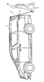
- FIG. 1 is a plan view illustrating an appearance of a vehicle to which the present disclosure is applied
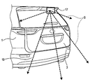
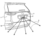
- FIG. 2 is a perspective view schematically showing the appearance of the back door provided in the vehicle and the operation of the object detection sensor provided in the back door.
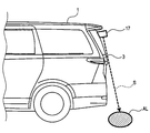
- FIG. 3 is an explanatory diagram showing the operation of the LED projector provided in the object detection sensor.
- FIG. 4 is an explanatory diagram showing the operation of the object detection sensor when the back door is opened and closed.
- FIG. 5 is an explanatory diagram showing an example of obstacle detection by the object detection sensor.
- FIG. 6 is an explanatory diagram showing another obstacle detection example by the object detection sensor, FIG.
- FIG. 7 is an explanatory diagram showing an example of gesture detection by the object detection sensor.
- FIG. 8 is an explanatory diagram schematically showing the field of view of the object detection sensor at the time of gesture detection
- FIG. 9 is a block diagram showing a configuration of a control system related to the object detection sensor
- FIG. 10 is a flowchart showing processing executed by the control system when the vehicle is stopped.
- FIG. 11 is a flowchart showing a process executed by the control system when the vehicle travels.
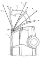
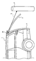
- FIG. 12 is a perspective view schematically showing a modification of the arrangement of the object detection sensors.
- the vehicle 1 shown in FIG. 1 includes at least a back door 3 and a pair of front side doors 5 as doors.
- the back door 3 is configured to be openable and closable toward the outside of the vehicle around a rotating shaft 3A (see FIG. 4) set in the horizontal direction (more specifically, in the left-right direction) above the rear portion of the vehicle 1. That is, the vehicle 1 is a so-called minivan type vehicle.
- the side doors 5 of the vehicle 1 are provided on the driver's seat side and the passenger's seat side, respectively, and open and close toward the outside of the vehicle 1 around the rotation shafts (not shown) set at the left and right fender rear ends of the vehicle 1. Is configured to be possible.
- the back door 3 (or the vehicle body in the vicinity thereof) is provided with an LF transmitting antenna 13.
- This LF transmitting antenna 13 is an antenna that transmits radio waves in the LF band (Low Frequency band), and has a communication range 13A narrower than an RF receiving antenna 23 (see FIG. 9) described later.
- the communication range 13 ⁇ / b> A of the LF transmission antenna 13 in this embodiment is slightly smaller than a circle whose diameter is the length in the left-right direction of the back door 3.
- the communication range 13 ⁇ / b> A reaches the outside of the vehicle behind the back door 3.
- Each side door 5 (or a vehicle body in the vicinity thereof) is provided with an LF transmission antenna 15.
- the communication range 15A of the LF transmission antenna 15 in this embodiment also has the same size as the communication range 13A of the LF transmission antenna 13.
- the communication range 15A reaches the outside of the vehicle on the outer side in the left-right direction of the side door 5 provided with the LF transmission antenna 15. Further, the communication range 13A and the pair of communication ranges 15A do not have overlapping portions.
- an object detection sensor 17 is provided on the outer surface of the upper end of the back door 3 (specifically, the upper end when closed).
- the object detection sensor 17 detects the presence or absence of an object in a predetermined space set on the free end side of the back door 3 and on the vehicle exterior side with respect to the back door 3.
- the object detection sensor 17 irradiates ultrasonic waves in various directions including the arrows S shown in FIG. 2 in a scanning manner, and acquires the shape of the object existing in the predetermined space.
- the object detection sensor 17 is configured by, for example, sonar.
- the predetermined space is disposed behind the rear bumper 19 of the vehicle 1.
- the predetermined space includes a range from at least a part of the free end (that is, the lower end) of the back door 3 to the ground when the back door 3 is closed.
- the object detection sensor 17 includes an LED light projecting unit 17A that irradiates light in a predetermined space (see FIG. 9). For this reason, when the back door 3 is closed, as shown in FIG. 3, there is a predetermined space between the irradiation area AL where the LED light projecting unit 17 ⁇ / b> A irradiates light on the ground and the object detection sensor 17. User D (see FIG. 7) can know.
- the LED light projecting unit 17A projects white or red light so that the irradiation area AL can be easily recognized even on asphalt or soil.
- the object detection sensor 17 is fixed to the back door 3, and a predetermined space (that is, the ultrasonic wave irradiation direction including the arrow S) is also fixed relatively to the back door 3. For this reason, when the back door 3 is opened as shown by an arrow C in FIG. 4, a predetermined space (that is, an ultrasonic wave irradiation direction including the arrow S) moves accordingly. 4 to 7, the back door 3 is schematically illustrated, and the object detection sensor 17 is not illustrated.
- the predetermined space reaches the ground at the rear of the vehicle 1 as described above.
- the user D of the vehicle 1 can cause the object detection sensor 17 to detect his / her foot F or the like.
- the foot F of the user D is detected in the scanning range AS of the object detection sensor 17 as shown in FIG. 8. Therefore, the user D can input some instruction to the vehicle 1 by moving the foot F in a predetermined pattern.
- the back door 3 can be instructed to be opened by moving the foot F in the left-right direction of the vehicle 1.
- the vehicle 1 in this embodiment includes a control system as shown in FIG. That is, the vehicle 1 includes a power tailgate drive unit 21, an RF reception antenna 23, a display 25, a shift position detector 27, a body ECU 30, and a smart entry in addition to the LF transmission antenna 13 and the object detection sensor 17 described above.
- An ECU 40 is provided.
- the object detection sensor 17 detects the presence or absence of the object B in the predetermined space. When the object B (for example, the foot F or an obstacle) exists in the predetermined space, the light emitted from the LED light projecting unit 17A is detected.
- the irradiation area AL is disposed on the object B as schematically shown in FIG.
- the power tailgate drive unit 21 is a known actuator that automatically drives the back door 3 to open.
- the RF receiving antenna 23 is an antenna that receives radio waves of RF band communication (Radio / Frequency / band communication).
- the display device 25 is a known display device that presents information to the user D seated in the driver's seat such as a driver's seat meter.
- the display device 25 may be a liquid crystal display device or a head-up display.
- the shift position detector 27 is a known detection device that detects the position of the shift lever of the vehicle 1.
- the body ECU 30 includes an MPU 31.
- the MPU 31 includes an object detection determination logic 31A and a tailgate operation determination logic 31B that are partitioned on software.
- the object detection determination logic 31A performs determination according to an object detection signal output as a result of object detection performed by the object detection sensor 17, and detects the presence or absence of an obstacle or a foot F.
- the tailgate operation determination logic 31B outputs a tailgate open signal for opening the back door 3 to the power tailgate drive unit 21.
- the MPU 31 may be an application specific integrated circuit (ASIC).
- the body ECU 30 includes various other logics for controlling the vehicle 1, but since it is not directly related to the present embodiment, the description is omitted here.
- the smart entry ECU 40 includes an MPU 41, an RF receiving IC 43, and an LF driver 45.
- a signal related to the radio wave received via the RF receiving antenna 23 is converted into data by the RF receiving IC 43 and sent to the body ECU 30 as an RF receiving signal.
- the MPU 41 outputs a signal to be transmitted from the LF transmission antenna 13, for example, a polling signal, to the LF driver 45 as an LF transmission signal.
- the LF driver 45 transmits the LF transmission signal as an LF band radio wave via the LF transmission antenna 13.
- the output intensity of the radio wave related to the LF band communication performed through the LF transmission antenna 13 is set according to the LF output intensity setting signal output from the RF reception IC 43 to the MPU 41.
- LF band communication performed via the LF transmission antenna 15 is similarly controlled by the LF driver 45.
- the body ECU 30 and the smart entry ECU 40 configured as described above are connected via a CAN 49. Further, the display unit 25 and the shift position detector 27 are also connected to the CAN 49. Note that CAN 49 may be replaced with communication between other in-vehicle ECUs.
- the portable device 50 carried by the user D can communicate with the LF transmission antenna 13 and the RF reception antenna 23 described above, and is configured as follows. First, various buttons such as a tailgate open button 51, a lock button 52, an unlock button 53,... Inside the portable device 50, a transmission / reception IC 55, an LF reception antenna 56, and an RF transmission antenna 57 are provided.
- the transmission / reception IC 55 executes, for example, the following control in response to operations of the tailgate open button 51, the lock button 52, the unlock button 53, and the like.
- the transmission / reception IC 55 transmits a signal for opening the back door 3 via the RF transmission antenna 57.
- the signal is sent to the body ECU 30 via the RF receiving antenna 23 and the smart entry ECU 40.
- the MPU 31 of the body ECU 30 instructs the power tailgate drive unit 21 to open the back door 3.
- the transmission / reception IC 55 transmits a signal for locking each door including the back door 3 and the pair of side doors 5 through the RF transmission antenna 57. Then, the signal is sent to the body ECU 30 via the RF receiving antenna 23 and the smart entry ECU 40. In that case, the MPU 31 of the body ECU 30 instructs a lock mechanism (not shown) to lock each door including the back door 3 and the pair of side doors 5.
- the transmission / reception IC 55 transmits a signal to unlock each door including the back door 3 and the pair of side doors 5 via the RF transmission antenna 57. Then, the signal is sent to the body ECU 30 via the RF receiving antenna 23 and the smart entry ECU 40. In that case, the MPU 31 of the body ECU 30 instructs a lock mechanism (not shown) to unlock the doors including the back door 3 and the pair of side doors 5.
- RF band radio waves have a wider communication range than LF band radio waves. Accordingly, the user D can give an instruction to the vehicle 1 by operating the tailgate open button 51, the lock button 52, the unlock button 53, etc., as described above, even from outside the communication ranges 13A to 15A. .
- the transmission / reception IC 55 performs a process of transmitting a signal indicating that the radio wave has been received via the RF transmission antenna 57.
- the MPU 41 of the smart entry ECU 40 executes control to transmit radio waves from the LF transmission antenna 13 as needed so that the processing is performed as soon as the portable device 50 enters the communication range 13A or 15A. This control is periodically executed even when the vehicle power is off. That is, the MPU 41 performs so-called polling via the LF transmission antenna 13.
- the MPU 31 of the body ECU 30 also executes the following processes.
- the body ECU 30 executes the process shown in the flowchart of FIG. 10 while the vehicle 1 is stopped (for example, when the shift position detected by the shift position detector 27 is in the P range). This process is repeatedly executed at a predetermined cycle while the vehicle 1 is stopped mainly by the tailgate operation determination logic 31B of the MPU 31.
- S1 it is determined whether or not there is a user D inside the communication range 13A (hereinafter also referred to as a back door area).
- the transmission / reception IC 55 of the portable device 50 carried by the user D transmits a signal indicating that the radio wave from the LF transmission antenna 13 has been received via the RF transmission antenna 57, which is transmitted via the RF reception antenna 23.
- the portable device 50 is detected in the back door area, it is assumed that the user D is in the back door area.
- S1: NO the process stands by in S1
- S1: YES the process proceeds to S2.
- the operation of the object detection sensor 17 is started, and the above-described LED light projecting unit 17A that illuminates the detection range (that is, the predetermined space) of the object detection sensor 17 is also turned on (that is, turned on).
- the detection range of the object detection sensor is also called a predetermined space.
- S4 it is determined whether or not a certain period of time has elapsed since the process of S2 was executed (that is, whether or not a timeout has occurred). If the certain period of time has not elapsed (S4: NO), the process is described above. The process proceeds to S3.
- the certain time is set in advance when the vehicle 1 is shipped.
- S11 it is determined whether or not an obstacle for continuing the door opening operation has been detected by the object detection sensor 17 in the predetermined space. Note that this determination and the determination in S3 described above are performed by the object detection determination logic 31A of the MPU 31 as a process applying known image analysis or the like. If no obstacle is detected (S11: NO), the process proceeds to S12. In S12, it is determined whether or not the back door 3 is fully opened. If the back door 3 is not fully opened (S12: NO), the process proceeds to S11 described above.
- one object detection sensor 17 provided for one back door 3 does not collide with the obstacle even if the object detection sensor 17 is a means for detecting a gesture for control to start the door opening operation.
- the object detection sensor 17 can also be used as a means for controlling to stop the door opening operation. For this reason, the cost for performing those controls can be suppressed. Therefore, the vehicle 1 having the convenience of instructing the door opening operation in a hands-free manner and the safety for suppressing the back door 3 from colliding with an obstacle is realized at a low cost by using a common sensor mechanism. be able to.
- the predetermined space and the irradiation area AL are disposed behind the rear bumper 19 of the vehicle 1. Therefore, it is not necessary for the user D to dive the foot F below the vehicle 1, and the starting operation is further facilitated.
- the body ECU 30 executes the process shown in the flowchart of FIG. 11 while the vehicle 1 is traveling (for example, when the shift position detected by the shift position detector 27 is outside the P range). This process is repeatedly executed at predetermined intervals while the vehicle 1 is traveling, mainly by the object detection determination logic 31A of the MPU 31.
- S31 it is determined via the shift position detector 27 whether or not the traveling state of the vehicle 1 is the back traveling state. If it is not in the reverse running state (S31: NO), the process ends as it is, and if it is in the reverse running state (S31: YES), the process proceeds to S32.
- S32 the operation of the object detection sensor 17 is started, and in subsequent S33, it is determined whether an obstacle is detected behind the vehicle 1 via the object detection sensor 17. If an obstacle is detected (S33: YES), the process proceeds to S34. In S34, a warning that there is an obstacle is continuously notified via the display device 25, and the process proceeds to S33 again.
- S33 when no obstacle is detected (S33: NO), the process proceeds to S35, and the warning is stopped when the notification of the warning is continued. If no warning has already been given when the process proceeds to S35, the process does not substantially do anything in S35 and proceeds to S37.
- S37 it is determined whether or not the vehicle 1 is powered off. If it is not off (S37: NO), the process proceeds to S33 described above. Therefore, during back travel, whether there is an obstacle behind the vehicle 1 is monitored (S33), and if there is an obstacle (S33: YES), a warning is given (S34).
- S37 When the power of the vehicle 1 is turned off (S37: YES), the operation of the object detection sensor 17 is stopped in S38, and the process is temporarily ended.
- the object detection sensor 17 that can be used both as a control means for starting the door opening operation and as a control means for stopping the door opening operation is further utilized during back travel. It is possible to suppress the vehicle 1 from colliding with an obstacle. Accordingly, the cost for executing these three types of control can be suppressed.
- the back door 3 is an example of an opening / closing body
- the power tailgate drive unit 21 is an example of an opening / closing body drive unit
- the object detection sensor 17 is an example of an object detection unit
- the tailgate operation determination logic 31B is As an example of the instruction unit
- the LF transmission antenna 13 and the RF reception antenna 23 are examples of the user detection unit
- the tailgate open button 51 is an example of the operation unit
- the portable device 50 is an example of the terminal
- the display unit 25 is the collision suppression.
- the object detection sensor 17 is provided at the upper end of the back door 3, but the present invention is not limited to this.
- an object detection sensor 17 may be provided at a position where a license plate (not shown) is provided.
- the object detection sensor 17 is schematically drawn larger, but it goes without saying that the object detection sensor 17 is provided so as not to prevent reading of the license plate.
- the vehicle 1 is a minivan type vehicle, but is not limited to this.
- the back door referred to in the present application is a concept including a rear hatch, a rear door, a tailgate, a hatchback, and the like.
- the present disclosure may be applied to the pair of side doors 5.
- the side door 5 is opened according to the control by which the side door 5 is prevented from colliding with another vehicle or the like parked adjacently and the gesture by the hand of the user D by the same processing as FIG. Control.
- the LF transmission antenna 15 provided on the pair of side doors 5 functions as a user detection unit that detects that the user D is within a predetermined distance from the side doors 5.
- the vehicle 1 can be prevented from colliding with other vehicles that run side by side at the time of width adjustment by the same processing as in FIG.
- the door opening operation is started (S10). It is not limited to.
- the shape of the object in the predetermined space may be image-analyzed to distinguish the user's instruction from the movement of the small animal.
- the object detection sensor 17 made of sonar or the like is used as the object detection unit, but the present invention is not limited to this.
- a capacitance sensor, a millimeter wave radar, an infrared sensor, a camera, or the like can also be used.
- the door opening operation restart after the obstacle detection is instructed by the tailgate opening button 51 (S14), but is not limited to this.
- resumption of the door opening operation may be instructed by a gesture.
- one object detection sensor 17 is provided for one back door 3, but the present invention is not limited to this.
- a plurality of object detection sensors 17 may be provided for one back door 3 to improve the detection accuracy and detection range of an obstacle or a foot F.
- a vehicle having the same detection accuracy and detection range is manufactured as compared with a case where a sensor for controlling to start the door opening operation and a sensor for controlling to stop the door opening operation are separately provided. In some cases, the cost for doing so can be reduced.
- the running process shown in FIG. 11 is not necessarily executed. Further, instead of the process shown in FIG. 11, a process of displaying an image of the rear of the vehicle 1 acquired via the object detection sensor 17 during back travel on the display device 25 may be performed.
- the LED light projecting unit 17A is used to indicate the position where the user D should perform the gesture, but the present invention is not limited to this.
- the LED light projecting unit 17A may be omitted, and a gesture may be performed using a license plate or the like as a mark.
- a light projecting unit other than an LED such as an incandescent lamp, may be used.
- the system including the vehicle 1 as a constituent element, a program for causing a computer to function as the body ECU 30 of the vehicle 1, a medium on which the program is recorded, a method for controlling the vehicle 1, etc.
- the present disclosure can also be realized.
- a vehicle opening / closing body driving device includes an opening / closing body driving unit that opens and opens an opening / closing body that can be opened toward the outside of a vehicle with a rotation axis set in the vehicle as a center, and an opening / closing body According to the detection result of the object detection unit and the object detection unit that detects the presence or absence of an object in a predetermined space set on the free end side of the opening / closing member and outside the vehicle with respect to the opening / closing member. And an instruction unit that instructs the opening / closing body drive unit to start and stop the opening operation of the opening / closing body.
- the opening / closing body driving unit opens the opening / closing body configured to be able to open toward the outside of the vehicle around the rotation axis set in the vehicle.
- An object detection unit provided in the opening / closing body detects the presence or absence of an object in a predetermined space in a non-contact manner.
- the predetermined space is a space set on the free end side of the opening / closing body and outside the vehicle with respect to the opening / closing body.
- the predetermined space is also a space where the user can easily give an instruction to open the opening / closing body from the outside of the vehicle. For this reason, when a user gives an instruction in a predetermined space, it is desirable to start the opening / closing body opening operation.
- the instruction unit instructs the opening / closing body driving unit to start and stop the opening operation of the opening / closing body according to the detection result of the object detection unit. For this reason, it is possible to execute control for opening the opening / closing body in accordance with a user instruction and control for stopping the opening operation to suppress the opening / closing body from colliding with an obstacle. Moreover, since the object detection unit can be used for two types of control such as start control and stop control of the opening operation, the cost for the control can be suppressed.
- each step is expressed as, for example, S1. Further, each step can be divided into a plurality of sub-steps, while a plurality of steps can be combined into one step.
Landscapes
- Engineering & Computer Science (AREA)
- Physics & Mathematics (AREA)
- Life Sciences & Earth Sciences (AREA)
- Mechanical Engineering (AREA)
- Remote Sensing (AREA)
- Geology (AREA)
- Environmental & Geological Engineering (AREA)
- General Life Sciences & Earth Sciences (AREA)
- General Physics & Mathematics (AREA)
- Geophysics (AREA)
- Acoustics & Sound (AREA)
- Power-Operated Mechanisms For Wings (AREA)
- Geophysics And Detection Of Objects (AREA)
Abstract
本開示の車両用開閉体駆動装置は、車両(1)に設定された回転軸を中心にして車外に向けて開動作可能な開閉体を、開動作させる開閉体駆動部(21)と、開閉体に設けられ、当該開閉体に対して当該開閉体の自由端側でかつ車外に設定された所定空間における物体の有無を、非接触で検出する物体検出部(17)と、物体検出部の検出結果に応じて、開閉体の開動作の開始及び停止を開閉体駆動部に指示する指示部(31B)と、を備える。
Description
本出願は、2015年1月23日に出願された日本国特許出願2015-11325号に基づくものであり、ここにその記載内容を参照により援用する。
本開示は、車両に設けられた開閉体を駆動する車両用開閉体駆動装置に関する。
従来、車両に設けられた開閉体としてのサイドドアやバックドアに非接触検知センサを設け、ユーザの手などを当該非接触検知センサが検知した場合に、サイドドア又はバックドアを自動で開動作させる技術が提案されている(例えば、特許文献1参照。)。
特許文献1では、非接触検知センサの前に手をかざすなどしてユーザが指示を行った場合にサイドドア又はバックドアを開閉することができる。ところが、特許文献1には、サイドドアやバックドアの開動作を途中で止める構成については開示されていない。サイドドアやバックドアの開動作中に当該ドアが何らかの障害物に衝突しそうになった場合には、当該開動作を停止するのが望ましい。なお、障害物はユーザの体である場合もあり、その場合は、開動作を停止する制御がなされなければ、ユーザはドアの移動範囲から退避する必要が生じうる。開動作を停止する制御を実行するために、障害物を検知するセンサを別途設ける方法も考えられるが、その場合、装置の製造コストが上昇しうる。
本開示は、ユーザの指示に応じて開閉体を開動作させる制御と、開閉体が障害物に衝突するのを抑制すべく開動作を停止する制御とが実行可能で、その制御のためのコストも抑制可能な技術の提供を目的としている。
本開示の一例によれば、車両用開閉体駆動装置は、開閉体駆動部と、物体検出部と、指示部とを備える。開閉体駆動部は、車両に設定された回転軸を中心にして車外に向けて開動作可能な開閉体を、開動作させる。物体検出部は、開閉体に設けられ、当該開閉体に対して当該開閉体の自由端側でかつ車外に設定された所定空間における物体の有無を、非接触で検出する。指示部は、物体検出部の検出結果に応じて、開閉体の開動作の開始及び停止を開閉体駆動部に指示する。
本開示の車両用開閉体駆動装置によれば、ユーザの指示に応じて開閉体を開動作させる制御と、開閉体が障害物に衝突するのを抑制すべく開動作を停止する制御とが可能であり、制御のためのコストを抑制することができる。
本開示についての上記および他の目的、特徴や利点は、添付図面を参照した下記詳細な説明から、より明確になる。添付図面において
図1は、本開示を適用した車用の外観を表す平面図であり、
図2は、車両に設けられたバックドアの外観、及び、バックドアに設けられた物体検出センサの動作を模式的に表す斜視図であり、
図3は、物体検出センサに設けられたLED投光部の動作を表す説明図であり、
図4は、バックドア開閉時の物体検出センサの動作を表す説明図であり、
図5は、物体検出センサによる障害物検出例を表す説明図であり、
図6は、物体検出センサによる他の障害物検出例を表す説明図であり、
図7は、物体検出センサによるジェスチャー検出例を表す説明図であり、
図8は、ジェスチャー検出時における物体検出センサの視野を模式的に表す説明図であり、
図9は、物体検出センサに係る制御系の構成を表すブロック図であり、
図10は、制御系が車両停車時に実行する処理を表すフローチャートであり、
図11は、制御系が車両走行時に実行する処理を表すフローチャートであり、
図12は、物体検出センサの配置の変形例を模式的に表す斜視図である。
以下、本開示が適用された実施形態について、図面を用いて説明する。
(1.第1実施形態)
(1-1.構成)
(1-1-1.機械的構成)
図1に示す車両1は、ドアとして、少なくとも、バックドア3及び一対の前側のサイドドア5を備えている。バックドア3は、車両1の後部上方において水平方向(より詳しくは左右方向)に設定された回転軸3A(図4参照)を中心にして車外に向けて開閉動作可能に構成されている。すなわち、車両1は、いわゆるミニバンタイプの車両である。車両1のサイドドア5は、運転席側と助手席側とにそれぞれ設けられ、車両1の左右それぞれのフェンダー後端に設定された回転軸(図示省略)を中心にして車外に向けて開閉動作可能に構成されている。
(1-1.構成)
(1-1-1.機械的構成)
図1に示す車両1は、ドアとして、少なくとも、バックドア3及び一対の前側のサイドドア5を備えている。バックドア3は、車両1の後部上方において水平方向(より詳しくは左右方向)に設定された回転軸3A(図4参照)を中心にして車外に向けて開閉動作可能に構成されている。すなわち、車両1は、いわゆるミニバンタイプの車両である。車両1のサイドドア5は、運転席側と助手席側とにそれぞれ設けられ、車両1の左右それぞれのフェンダー後端に設定された回転軸(図示省略)を中心にして車外に向けて開閉動作可能に構成されている。
図1に模式的に示すように、バックドア3(又はその近傍の車体)には、LF送信アンテナ13が設けられている。このLF送信アンテナ13は、LF帯(Low Frequency 帯)の電波を送信するアンテナで、後述のRF受信アンテナ23(図9参照)に比べて通信範囲13Aが狭い。図1に模式的に示すように、本実施形態におけるLF送信アンテナ13の通信範囲13Aは、バックドア3の左右方向長さを直径とする円よりも若干小さい。しかしながら、通信範囲13Aは、バックドア3の後方の車外にも達している。
各サイドドア5(又はその近傍の車体)には、LF送信アンテナ15がそれぞれ設けられている。本実施形態におけるLF送信アンテナ15の通信範囲15Aも、LF送信アンテナ13の通信範囲13Aと同様の大きさを有している。その通信範囲15Aは、当該LF送信アンテナ15が設けられたサイドドア5の左右方向外側の車外にも達している。また通信範囲13A及び一対の通信範囲15Aは、重複部分を有さない。
バックドア3の上端部(詳しくは、閉鎖時における上端部)外面には、図2に模式的に示すように、物体検出センサ17が設けられている。この物体検出センサ17は、バックドア3に対して当該バックドア3の自由端側でかつ車外側に設定された所定空間における物体の有無を非接触で検出する。具体的には、例えば、物体検出センサ17は、図2に示す各矢印Sを含む各種方向に超音波を走査状に照射し、当該所定空間に存在する物体の形状等を取得する。物体検出センサ17は、例えばソナー等によって構成される。また、所定空間は、車両1の後部バンパ19よりも後方に配設される。
所定空間は、バックドア3の閉鎖時に当該バックドア3の自由端(すなわち下端)の少なくとも一部から地面に至る範囲を含んでいる。また、物体検出センサ17は、所定空間内に光を照射するLED投光部17Aを備えている(図9参照)。このため、バックドア3の閉鎖時には、図3に示すように、LED投光部17Aが地面に光を照射する照射領域ALと物体検出センサ17との間に、所定空間が存在することを、ユーザD(図7参照)は知ることができる。なお、LED投光部17Aは、アスファルトや土の上でも照射領域ALが容易に認識されるように、白又は赤の光を投光する。
また、物体検出センサ17はバックドア3に固定されており、所定空間(すなわち、矢印Sを含む超音波照射方向)も、バックドア3に対して相対的に固定されている。このため、図4に矢印Cで示すようにバックドア3が開放されると、それに伴って所定空間(すなわち、矢印Sを含む超音波照射方向)も移動する。なお、図4~図7では、バックドア3を模式的に図示し、物体検出センサ17の図示を省略する。
このため、図5に例示するように、車両1の後方におけるバックドア3の回転範囲内に、ポールPが存在する場合、当該バックドア3がポールPに衝突する前に、物体検出センサ17によってポールPが検出される。同様に、図6に例示するように、車両1の後方かつ上方におけるバックドア3の回転範囲内に、ガレージGの天井GAが存在する場合、当該バックドア3が天井GAに衝突する前に、物体検出センサ17によって天井GAが検出される。
また、車両1がバックドア3を閉じた状態で停車しているとき、所定空間は、前述のように、車両1の後部の地面まで達している。このため、当該車両1のユーザDは、自身の足F等を、物体検出センサ17に検出させることができる。ユーザDが図7に示す位置にいる場合、図8に示すように、物体検出センサ17の走査範囲ASには、ユーザDの足Fが検出される。このため、ユーザDは、足Fを所定のパターンで動かすことにより、車両1に何らかの指示を入力することができる。例えば、足Fを車両1の左右方向に動かすことにより、バックドア3の開放を指示することができる。
(1-1-2.制御系の構成)
そこで、本実施形態における車両1は、図9に示すような制御系を備えている。すなわち、車両1は、前述のLF送信アンテナ13,物体検出センサ17に加えて、パワーテールゲート駆動部21、RF受信アンテナ23、表示機25、シフト位置検出器27、ボデーECU30、及び、スマートエントリーECU40を備えている。なお、前述のように物体検出センサ17は所定空間における物体Bの有無等を検出し、その所定空間に物体B(例えば足F又は障害物)が存在する場合、LED投光部17Aによる光の照射領域ALが、図9に模式的に示すようにその物体B上に配設される。
そこで、本実施形態における車両1は、図9に示すような制御系を備えている。すなわち、車両1は、前述のLF送信アンテナ13,物体検出センサ17に加えて、パワーテールゲート駆動部21、RF受信アンテナ23、表示機25、シフト位置検出器27、ボデーECU30、及び、スマートエントリーECU40を備えている。なお、前述のように物体検出センサ17は所定空間における物体Bの有無等を検出し、その所定空間に物体B(例えば足F又は障害物)が存在する場合、LED投光部17Aによる光の照射領域ALが、図9に模式的に示すようにその物体B上に配設される。
パワーテールゲート駆動部21は、バックドア3を自動で開駆動させる周知のアクチュエータである。RF受信アンテナ23は、RF帯通信(Radio Frequency 帯通信)の電波を受信するアンテナである。表示機25は、運転席のメータ等、運転席に着座したユーザDに情報を提示する周知の表示装置である。例えば、表示機25は液晶表示装置であってもよく、ヘッドアップディスプレイであってもよい。シフト位置検出器27は、車両1のシフトレバーの位置を検出する周知の検出装置である。
ボデーECU30は、MPU31を備えている。このMPU31は、ソフトウェア上で区分された物体検出判定ロジック31Aとテールゲート動作判定ロジック31Bとを備えている。物体検出判定ロジック31Aは、物体検出センサ17が物体検出を行った結果として出力する物体検出信号に応じた判定を行い、障害物や足Fの有無等を検出する。物体検出判定ロジック31Aによる検出状態に応じて、テールゲート動作判定ロジック31Bは、バックドア3を開動作させるためのテールゲート開信号をパワーテールゲート駆動部21に出力する。なお、MPU31は、特定用途向け集積回路(ASIC)であってもよい。また、ボデーECU30は、以外にも車両1を制御するためのロジックを種々備えているが、本実施形態とは直接関係がないため、ここでは説明を割愛する。
スマートエントリーECU40は、MPU41と、RF受信IC43と、LFドライバ45とを備えている。RF受信アンテナ23を介して受信された電波に係る信号は、RF受信IC43によってデータ化され、RF受信信号としてボデーECU30へ送られる。また、MPU41は、LFドライバ45に、LF送信アンテナ13から送信すべき信号、例えばポーリング用の信号を、LF送信信号として出力する。すると、LFドライバ45は、LF送信アンテナ13を介して、当該LF送信信号をLF帯の電波として送信する。なお、このようにLF送信アンテナ13を介してなされるLF帯通信に係る電波の出力強度は、RF受信IC43からMPU41へ出力されるLF出力強度設定信号に応じて設定される。また、図9では図示省略したが、LF送信アンテナ15を介してなされるLF帯通信も同様にLFドライバ45によって制御される。
このように構成されたボデーECU30及びスマートエントリーECU40は、CAN49を介して接続されている。また、当該CAN49には、表示機25及びシフト位置検出器27も接続されている。なお、CAN49は、その他の車内ECU間通信に代えられてもよい。
次に、ユーザDが携帯する携帯機50は、前述のLF送信アンテナ13及びRF受信アンテナ23との通信が可能であり、次のように構成されている。先ず、携帯機50の図示省略した筐体表面には、テールゲート開ボタン51,ロックボタン52,アンロックボタン53,…といった各種ボタンが設けられている。携帯機50の内部には、送受信IC55と、LF受信アンテナ56と、RF送信アンテナ57とが設けられている。
送受信IC55は、テールゲート開ボタン51,ロックボタン52,アンロックボタン53等の操作に応じて、例えば次のような制御を実行する。テールゲート開ボタン51が操作された場合、送受信IC55は、バックドア3を開ける旨の信号を、RF送信アンテナ57を介して送信する。すると、その信号がRF受信アンテナ23及びスマートエントリーECU40を介してボデーECU30へ送られる。その場合、ボデーECU30のMPU31は、パワーテールゲート駆動部21にバックドア3を開けるように指示する。
また、ロックボタン52が操作された場合、送受信IC55は、バックドア3及び一対のサイドドア5を含む各ドアをロックする旨の信号を、RF送信アンテナ57を介して送信する。すると、その信号がRF受信アンテナ23及びスマートエントリーECU40を介してボデーECU30へ送られる。その場合、ボデーECU30のMPU31は、バックドア3及び一対のサイドドア5を含む各ドアをロックするように、図示省略したロック機構に指示する。
また、アンロックボタン53が操作された場合、送受信IC55は、バックドア3及び一対のサイドドア5を含む各ドアのロックを解除する旨の信号を、RF送信アンテナ57を介して送信する。すると、その信号がRF受信アンテナ23及びスマートエントリーECU40を介してボデーECU30へ送られる。その場合、ボデーECU30のMPU31は、バックドア3及び一対のサイドドア5を含む各ドアのロックを解除するように、図示省略したロック機構に指示する。
なお、RF帯の電波はLF帯の電波に比べて通信範囲が広い。従って、ユーザDは、前述の通信範囲13A~15Aの外部からでも、前述のようにテールゲート開ボタン51,ロックボタン52,アンロックボタン53等を操作して車両1に指示を与えることができる。また、LF受信アンテナ56が車両1のLF送信アンテナ13から電波を受信した場合、送受信IC55は、当該電波を受信した旨の信号を、RF送信アンテナ57を介して送信する処理を行う。スマートエントリーECU40のMPU41は、通信範囲13A又は15Aの内側に携帯機50が入ったらすぐにその処理がなされるように、LF送信アンテナ13から電波を随時送信する制御を実行する。この制御は、車両電源がオフの間も定期的に実行される。すなわち、MPU41は、LF送信アンテナ13を介していわゆるポーリングを実行する。
(1-2.処理)
(1-2-1.停車中の処理)
ボデーECU30のMPU31は、これらの一般的な処理に加えて、次のような処理も実行する。ボデーECU30は、車両1の停車中(例えば、シフト位置検出器27に検出されるシフト位置がPレンジである場合)、図10のフローチャートに示す処理を実行する。なお、この処理は、主としてMPU31のテールゲート動作判定ロジック31Bにより、車両1の停車中に所定周期で繰り返し実行される。
(1-2-1.停車中の処理)
ボデーECU30のMPU31は、これらの一般的な処理に加えて、次のような処理も実行する。ボデーECU30は、車両1の停車中(例えば、シフト位置検出器27に検出されるシフト位置がPレンジである場合)、図10のフローチャートに示す処理を実行する。なお、この処理は、主としてMPU31のテールゲート動作判定ロジック31Bにより、車両1の停車中に所定周期で繰り返し実行される。
図10に示すように、この処理では、先ず、S1にて、通信範囲13Aの内側(以下、バックドアエリアともいう。)にユーザDがいるか否かが判断される。この判断は、ユーザDに携帯される携帯機50の送受信IC55が、LF送信アンテナ13からの電波を受信した旨の信号をRF送信アンテナ57を介して送信し、それがRF受信アンテナ23を介して受信されたか否かに応じてなされる。すなわち、本実施形態では、バックドアエリアに携帯機50が検出された場合に、バックドアエリアにユーザDがいるものとみなしている。バックドアエリアにユーザDがいないときは(S1:NO)、処理はそのままS1にて待機し、バックドアエリアにユーザDがいるときは(S1:YES)、処理はS2へ移行する。
S2では、物体検出センサ17の作動が開始され、その物体検出センサ17の検出範囲(すなわち所定空間)を照明する前述のLED投光部17Aも点灯制御(すなわちオン)される。物体検出センサの検出範囲は、所定空間とも呼ぶ。続くS3では、バックドア3を開くために予め設定されたジェスチャーが、所定空間において物体検出センサ17によって検出されたか否かが判断される。例えば、前述のように、所定空間において足Fを車両1の左右方向に動かすジェスチャーが検出されたか否かが判断される。ジェスチャーが検出されていないときは(S3:NO)、処理はS4へ移行する。S4では、S2の処理が実行されてから一定時間が経過したか否か(すなわち、タイムアウトしたか否か)が判断され、一定時間が経過していない場合は(S4:NO)、処理は前述のS3へ移行する。なお、この一定時間は、車両1の出荷時に予め設定されている。
このため、ジェスチャーが検出されない場合は(S3:NO)、一定時間が経過するまで、S3,S4の処理が繰り返し実行される。そして、ジェスチャーが検出されるまでに一定時間が経過すると(S4:YES)、処理はS5へ移行する。S5では、物体検出センサ17の検出範囲を照明するLED投光部17Aが消灯制御(すなわちオフ)される。続くS6では、物体検出センサ17の作動が停止され、処理が一旦終了する。
一方、S3,S4の処理が繰り返し実行されている間に、一定時間が経過するまでにジェスチャーが検出されると(S3:YES)、処理はS10へ移行する。S10では、パワーテールゲート駆動部21を介してバックドア3を自動で開く動作が開始され、かつ、LED投光部17Aがオフされる。バックドアを自動で開く動作はドア開動作とも呼ぶ。
S10に続くS11では、ドア開動作を継続する上での障害物が所定空間内に物体検出センサ17によって検出されたか否かが判断される。なお、この判断や前述のS3における判断は、MPU31の物体検出判定ロジック31Aによって、周知の画像解析等を応用した処理としてなされる。そして、障害物が検出されていない場合は(S11:NO)、処理はS12へ移行する。S12では、バックドア3が全開になったか否かが判断され、全開になっていない場合は(S12:NO)、処理は前述のS11へ移行する。
このため、バックドア3の回転範囲に障害物が存在しない場合は(S11:NO)、バックドア3が全開になるまで、S11,S12の処理が繰り返し実行される。そして、障害物が検出されることなく(S11:NO)、バックドア3が全開となると(S12:YES)、処理は前述のS6へ移行する。
一方、S11,S12の処理が繰り返し実行されている間に、バックドア3が全開になるまでに障害物が検出されると(S11:YES)、処理はS13へ移行する。S13では、ドア開動作が停止される。続くS14では、携帯機50のテールゲート開ボタン51が操作されるなど、ドア開動作を指示するための従来と同様の操作が、ドア開動作が停止してから一定時間内になされたか否かが判断される。一定時間内に当該操作がなされていない場合は(S14:NO)、処理は前述のS6へ移行し、一定時間内に当該操作がなされた場合は(S14:YES)、S15にてドア開動作が再開された後、処理は前述のS11へ移行する。
(1-2-2.停車中の処理の効果)
停車中の処理により、次のような効果が生じる。
停車中の処理により、次のような効果が生じる。
(1A)
この処理では、物体検出センサ17によって所定空間においてジェスチャーが検出されると(S3:YES)、ドア開動作が開始される(S10)。このため、ユーザDが両手で荷物を持っている場合にも、足Fでジェスチャーをすることによって容易にバックドア3を開けることができる。また、ドア開動作中に(S11,S12)、物体検出センサ17によって所定空間において障害物が検出されると(S11:YES)、ドア開動作が停止される(S13)。このため、バックドア3がポールP等の障害物に衝突するのを抑制することができる。
この処理では、物体検出センサ17によって所定空間においてジェスチャーが検出されると(S3:YES)、ドア開動作が開始される(S10)。このため、ユーザDが両手で荷物を持っている場合にも、足Fでジェスチャーをすることによって容易にバックドア3を開けることができる。また、ドア開動作中に(S11,S12)、物体検出センサ17によって所定空間において障害物が検出されると(S11:YES)、ドア開動作が停止される(S13)。このため、バックドア3がポールP等の障害物に衝突するのを抑制することができる。
すなわち、1つのバックドア3に対して1つ設けられた物体検出センサ17は、ドア開動作を開始する制御のためにジェスチャーを検出するための手段としても、障害物にバックドア3が衝突しないようにドア開動作を停止させる制御のための手段としても、兼用することができる。このため、それらの制御を実行するためのコストを抑制することができる。従って、ハンズフリーでドア開動作を指示できる利便性と、バックドア3が障害物と衝突するのを抑制する安全性とを備えた車両1を、共通のセンサ機構を用いて低コストで実現することができる。
(1B)
上記処理では、物体検出センサ17の動作開始時に、LED投光部17Aをオンして所定空間内に光を照射している(S2)。このため、バックドア3が閉鎖されている状態では、LED投光部17Aが地面に光を照射する照射領域ALと物体検出センサ17との間に、所定空間が存在することを、ユーザDは知ることができる。従って、ジェスチャーを物体検出センサ17に検出させてドア開動作を開始させる操作が、一層容易になる。
上記処理では、物体検出センサ17の動作開始時に、LED投光部17Aをオンして所定空間内に光を照射している(S2)。このため、バックドア3が閉鎖されている状態では、LED投光部17Aが地面に光を照射する照射領域ALと物体検出センサ17との間に、所定空間が存在することを、ユーザDは知ることができる。従って、ジェスチャーを物体検出センサ17に検出させてドア開動作を開始させる操作が、一層容易になる。
(1C)
しかも、所定空間及び照射領域ALは、車両1の後部バンパ19よりも後方に配設される。従って、ユーザDは足Fを車両1の下方に潜り込ませる必要はなく、開始させる操作がより一層容易になる。
しかも、所定空間及び照射領域ALは、車両1の後部バンパ19よりも後方に配設される。従って、ユーザDは足Fを車両1の下方に潜り込ませる必要はなく、開始させる操作がより一層容易になる。
(1D)
上記処理では、携帯機50がバックドアエリアに存在することによりユーザDもそのバックドアエリアにいるとみなされた場合であって(S1:YES)、かつ、ジェスチャーが検出された場合に(S3:YES)、ドア開動作が開始される(S10)。このため、ユーザD以外の他人によるジェスチャーや小動物の動作によって、誤ってドア開動作が開始されるのを抑制することができる。
上記処理では、携帯機50がバックドアエリアに存在することによりユーザDもそのバックドアエリアにいるとみなされた場合であって(S1:YES)、かつ、ジェスチャーが検出された場合に(S3:YES)、ドア開動作が開始される(S10)。このため、ユーザD以外の他人によるジェスチャーや小動物の動作によって、誤ってドア開動作が開始されるのを抑制することができる。
(1E)
ドア開動作中に(S11,S12)、物体検出センサ17によって所定空間において障害物が検出されると(S11:YES)、ドア開動作が停止される(S13)。この障害物は人間であってもよく、更にユーザDであってもよい。このため、ユーザDはドア開動作中のバックドア3の後方に手を差し出すなどして、ドア開動作を意図的に停止させることもできる。
ドア開動作中に(S11,S12)、物体検出センサ17によって所定空間において障害物が検出されると(S11:YES)、ドア開動作が停止される(S13)。この障害物は人間であってもよく、更にユーザDであってもよい。このため、ユーザDはドア開動作中のバックドア3の後方に手を差し出すなどして、ドア開動作を意図的に停止させることもできる。
(1F)
上記処理では、障害物が検出されたことによりドア開動作が停止された場合は(S13)、テールゲート開ボタン51が操作されるなどの従来と同様の指示がなされるまでドア開動作が再開されない。このため、次のような効果が生じる。例えば、バックドア3の後方に他車両が停車している場合に、当該他車両が障害物として検出されたことによりドア開動作が停止されることがある。その場合、他車両はいつ動き出すか分からない。言い換えれば、ドア開動作を停止させている障害物がいつなくなるか分からない。これに対して、処理では、ユーザDが意図的にテールゲート開ボタン51を操作するまでドア開動作が再開されないので、安全性が一層向上する。
上記処理では、障害物が検出されたことによりドア開動作が停止された場合は(S13)、テールゲート開ボタン51が操作されるなどの従来と同様の指示がなされるまでドア開動作が再開されない。このため、次のような効果が生じる。例えば、バックドア3の後方に他車両が停車している場合に、当該他車両が障害物として検出されたことによりドア開動作が停止されることがある。その場合、他車両はいつ動き出すか分からない。言い換えれば、ドア開動作を停止させている障害物がいつなくなるか分からない。これに対して、処理では、ユーザDが意図的にテールゲート開ボタン51を操作するまでドア開動作が再開されないので、安全性が一層向上する。
(1-2-3.走行中の処理)
ボデーECU30は、車両1の走行中(例えば、シフト位置検出器27に検出されるシフト位置がPレンジ以外である場合)、図11のフローチャートに示す処理を実行する。なお、この処理は、主としてMPU31の物体検出判定ロジック31Aにより、車両1の走行中に所定周期で繰り返し実行される。
ボデーECU30は、車両1の走行中(例えば、シフト位置検出器27に検出されるシフト位置がPレンジ以外である場合)、図11のフローチャートに示す処理を実行する。なお、この処理は、主としてMPU31の物体検出判定ロジック31Aにより、車両1の走行中に所定周期で繰り返し実行される。
図11に示すように、この処理では、先ず、S31にて、車両1の走行状態がバック走行の状態であるか否かがシフト位置検出器27を介して判断される。バック走行の状態でない場合は(S31:NO)、処理はそのまま終了し、バックの走行状態である場合は(S31:YES)、処理はS32へ移行する。S32では、物体検出センサ17の動作が開始され、続くS33では、その物体検出センサ17を介して車両1の後方に障害物が検出されたか否かが判断される。障害物が検出された場合は(S33:YES)、処理はS34へ移行する。S34では、表示機25を介して、障害物がある旨の警告が継続的に通知され、再び処理はS33へ移行する。
一方、障害物が検出されない場合は(S33:NO)、処理はS35へ移行し、警告の通知が継続中の場合に当該警告が中止される。なお、処理がS35へ移行した時点ですでに警告がなされていなかった場合は、処理はS35では実質的に何もせず、そのまま続くS37へ移行する。S37では、車両1の電源がオフであるか否かが判断される。オフでない場合は(S37:NO)、処理は前述のS33へ移行する。このため、バック走行中は、車両1の後方に障害物があるか否かが監視され(S33)、障害物がある場合は(S33:YES)、警告がなされる(S34)。そして、車両1の電源がオフされると(S37:YES)、S38にて物体検出センサ17の動作が停止され、処理が一旦終了する。
(1-2-4.走行中の処理の効果)
走行中の処理により、次のような効果が生じる。すなわち、ドア開動作を開始する制御のための手段としても、ドア開動作を停止させる制御のための手段としても、兼用することができた物体検出センサ17を、更に活用して、バック走行時に車両1が障害物に衝突するのを抑制することができる。従って、これらの3種類の制御を実行するためのコストを抑制することができる。
走行中の処理により、次のような効果が生じる。すなわち、ドア開動作を開始する制御のための手段としても、ドア開動作を停止させる制御のための手段としても、兼用することができた物体検出センサ17を、更に活用して、バック走行時に車両1が障害物に衝突するのを抑制することができる。従って、これらの3種類の制御を実行するためのコストを抑制することができる。
なお、実施形態において、バックドア3が開閉体の一例に、パワーテールゲート駆動部21が開閉体駆動部の一例に、物体検出センサ17が物体検出部の一例に、テールゲート動作判定ロジック31Bが指示部の一例に、LF送信アンテナ13及びRF受信アンテナ23がユーザ検出部の一例に、テールゲート開ボタン51が操作部の一例に、携帯機50が端末の一例に、表示機25が衝突抑制部の一例に、それぞれ相当する。
(2.他の実施形態)
以上、本開示の実施形態について説明したが、本開示は実施形態に限定されることなく、種々の形態を採り得る。
以上、本開示の実施形態について説明したが、本開示は実施形態に限定されることなく、種々の形態を採り得る。
(2A)
本実施形態では、バックドア3の上端部に物体検出センサ17を設けたが、これに限定されるものではない。例えば、図12に示すように、ナンバープレート(図示省略)の配設位置に物体検出センサ17を設けてもよい。なお、図12では、物体検出センサ17を模式的に大きめに描いているが、ナンバープレートの読取を妨げないように物体検出センサ17が設けられることは言うまでもない。
本実施形態では、バックドア3の上端部に物体検出センサ17を設けたが、これに限定されるものではない。例えば、図12に示すように、ナンバープレート(図示省略)の配設位置に物体検出センサ17を設けてもよい。なお、図12では、物体検出センサ17を模式的に大きめに描いているが、ナンバープレートの読取を妨げないように物体検出センサ17が設けられることは言うまでもない。
(2B)
本実施形態では、車両1をミニバンタイプの車両としたが、これに限定されるものではない。本願で言うバックドアとは、リアハッチ,リアドア,テールゲート,ハッチバック等も含む概念である。
本実施形態では、車両1をミニバンタイプの車両としたが、これに限定されるものではない。本願で言うバックドアとは、リアハッチ,リアドア,テールゲート,ハッチバック等も含む概念である。
(2C)
本実施形態では、開閉体の一例としてのバックドア3に本開示を適用したが、これに限定されるものではない。例えば、一対のサイドドア5に本開示を適用してもよい。その場合、図10と同様の処理により、サイドドア5が隣接して駐車された他車両等に衝突するのを抑制する制御と、ユーザDの手によるジェスチャーに応じてサイドドア5を開動作させる制御とを実行することができる。また、その場合、一対のサイドドア5に設けられたLF送信アンテナ15が、当該サイドドア5から所定距離以内にユーザDがいることを検出するユーザ検出部として機能する。また、その場合、図11と同様の処理により、走行中の幅寄せ時に併走する他車両に車両1が衝突するのを抑制することができる。
本実施形態では、開閉体の一例としてのバックドア3に本開示を適用したが、これに限定されるものではない。例えば、一対のサイドドア5に本開示を適用してもよい。その場合、図10と同様の処理により、サイドドア5が隣接して駐車された他車両等に衝突するのを抑制する制御と、ユーザDの手によるジェスチャーに応じてサイドドア5を開動作させる制御とを実行することができる。また、その場合、一対のサイドドア5に設けられたLF送信アンテナ15が、当該サイドドア5から所定距離以内にユーザDがいることを検出するユーザ検出部として機能する。また、その場合、図11と同様の処理により、走行中の幅寄せ時に併走する他車両に車両1が衝突するのを抑制することができる。
(2D)
本実施形態では、バックドアエリアに携帯機50が存在し(S1:YES)、かつ、ジェスチャーが検出された場合に(S3:YES)、ドア開動作を開始しているが(S10)、これに限定されるものではない。例えば、小動物の動きとユーザDのジェスチャーとを区別するためには、所定空間内の物体の形状を画像解析して、ユーザの指示と小動物の動きとを区別してもよい。
本実施形態では、バックドアエリアに携帯機50が存在し(S1:YES)、かつ、ジェスチャーが検出された場合に(S3:YES)、ドア開動作を開始しているが(S10)、これに限定されるものではない。例えば、小動物の動きとユーザDのジェスチャーとを区別するためには、所定空間内の物体の形状を画像解析して、ユーザの指示と小動物の動きとを区別してもよい。
(2E)
本実施形態では、物体検出部としてソナー等からなる物体検出センサ17を用いているが、これに限定されるものではない。物体検出部としては、静電容量センサ、ミリ波レーダ、赤外線センサ、カメラ等も利用することができる。
本実施形態では、物体検出部としてソナー等からなる物体検出センサ17を用いているが、これに限定されるものではない。物体検出部としては、静電容量センサ、ミリ波レーダ、赤外線センサ、カメラ等も利用することができる。
(2F)
本実施形態では、障害物検出後のドア開動作再開はテールゲート開ボタン51によって指示されるが(S14)、これに限定されるものではない。例えば、ドア開動作の再開はジェスチャーによって指示されてもよい。
本実施形態では、障害物検出後のドア開動作再開はテールゲート開ボタン51によって指示されるが(S14)、これに限定されるものではない。例えば、ドア開動作の再開はジェスチャーによって指示されてもよい。
(2G)
本実施形態における走行中の処理では、バック走行中に(S31:YES)、障害物が検出されると(S33:YES)、警告がなされるが(S34)、これに限定されるものではない。例えば、バック走行中に障害物が検出された場合、自動的に制動を行ってもよい。
本実施形態における走行中の処理では、バック走行中に(S31:YES)、障害物が検出されると(S33:YES)、警告がなされるが(S34)、これに限定されるものではない。例えば、バック走行中に障害物が検出された場合、自動的に制動を行ってもよい。
(2H)
本実施形態では、1つのバックドア3に対して1つの物体検出センサ17を設けているが、これに限定されるものではない。例えば、1つのバックドア3に対して複数の物体検出センサ17を設けておき、障害物や足Fの検出精度及び検出範囲を向上させてもよい。その場合も、ドア開動作を開始する制御のためのセンサとドア開動作を停止させる制御のためのセンサとを別個に設ける場合に比べて、同様の検出精度及び検出範囲を備えた車両を製造するためのコストを低減させることができる場合がある。
本実施形態では、1つのバックドア3に対して1つの物体検出センサ17を設けているが、これに限定されるものではない。例えば、1つのバックドア3に対して複数の物体検出センサ17を設けておき、障害物や足Fの検出精度及び検出範囲を向上させてもよい。その場合も、ドア開動作を開始する制御のためのセンサとドア開動作を停止させる制御のためのセンサとを別個に設ける場合に比べて、同様の検出精度及び検出範囲を備えた車両を製造するためのコストを低減させることができる場合がある。
(2I)
本実施形態では、ジェスチャーの検出時に(S3:YES)、ドア開動作を開始させ(S10)、障害物の検出時に(S11:YES)、ドア開動作を停止させているが(S13)、これに限定されるものではない。物体検出センサ17がどのような検出を行ったときにドア開動作を開始させ、物体検出センサ17がどのような検出を行ったときにドア開動作を停止させるかは、種々に変更することができる。また、ジェスチャーとしても種々の形態が考えられる。例えば、所定空間に足Fをモールス信号のように所定のタイミングで挿入するジェスチャーであれば、物体検出センサ17は、物体の有無のみが検出可能で、物体の移動方向や形状まで検出できないものであってもよい。
本実施形態では、ジェスチャーの検出時に(S3:YES)、ドア開動作を開始させ(S10)、障害物の検出時に(S11:YES)、ドア開動作を停止させているが(S13)、これに限定されるものではない。物体検出センサ17がどのような検出を行ったときにドア開動作を開始させ、物体検出センサ17がどのような検出を行ったときにドア開動作を停止させるかは、種々に変更することができる。また、ジェスチャーとしても種々の形態が考えられる。例えば、所定空間に足Fをモールス信号のように所定のタイミングで挿入するジェスチャーであれば、物体検出センサ17は、物体の有無のみが検出可能で、物体の移動方向や形状まで検出できないものであってもよい。
(2J)
図11に示した走行中の処理は、必ずしも実行されなくてもよい。また、図11に示した処理の代わりに、バック走行時に物体検出センサ17を介して取得される車両1後方の映像を表示機25に表示する処理がなされてもよい。
図11に示した走行中の処理は、必ずしも実行されなくてもよい。また、図11に示した処理の代わりに、バック走行時に物体検出センサ17を介して取得される車両1後方の映像を表示機25に表示する処理がなされてもよい。
(2K)
本実施形態では、ユーザDがジェスチャーを行うべき位置を示すためにLED投光部17Aを利用しているが、これに限定されるものではない。例えば、LED投光部17Aを省略し、ナンバープレート等を目印にしてジェスチャーを行うようにしてもよい。また、例えば白熱灯等、LED以外の投光部を用いてもよいことは言うまでもない。
本実施形態では、ユーザDがジェスチャーを行うべき位置を示すためにLED投光部17Aを利用しているが、これに限定されるものではない。例えば、LED投光部17Aを省略し、ナンバープレート等を目印にしてジェスチャーを行うようにしてもよい。また、例えば白熱灯等、LED以外の投光部を用いてもよいことは言うまでもない。
(2L)
本実施形態における1つの構成要素が有する機能を複数の構成要素として分散させたり、複数の構成要素が有する機能を1つの構成要素に統合させたりしてもよい。また、実施形態の構成の一部を省略してもよい。また、実施形態の構成の少なくとも一部を、他の実施形態の構成に対して付加又は置換してもよい。
本実施形態における1つの構成要素が有する機能を複数の構成要素として分散させたり、複数の構成要素が有する機能を1つの構成要素に統合させたりしてもよい。また、実施形態の構成の一部を省略してもよい。また、実施形態の構成の少なくとも一部を、他の実施形態の構成に対して付加又は置換してもよい。
(2M)
上述した車両1の他、当該車両1を構成要素とするシステム、当該車両1のボデーECU30としてコンピュータを機能させるためのプログラム、このプログラムを記録した媒体、車両1の制御方法など、種々の形態で本開示を実現することもできる。
上述した車両1の他、当該車両1を構成要素とするシステム、当該車両1のボデーECU30としてコンピュータを機能させるためのプログラム、このプログラムを記録した媒体、車両1の制御方法など、種々の形態で本開示を実現することもできる。
以上、本開示によれば様々な態様の車両用開閉体駆動装置が提供される。例えば、本開示の一態様の車両用開閉体駆動装置は、車両に設定された回転軸を中心にして車外に向けて開動作可能な開閉体を、開動作させる開閉体駆動部と、開閉体に設けられ、当該開閉体に対して当該開閉体の自由端側でかつ車外に設定された所定空間における物体の有無を、非接触で検出する物体検出部と、物体検出部の検出結果に応じて、開閉体の開動作の開始及び停止を開閉体駆動部に指示する指示部と、を備える。
本開示の車両用開閉体駆動装置によれば、開閉体駆動部は、車両に設定された回転軸を中心にして車外に向けて開動作可能に構成された開閉体を、開動作させる。開閉体に設けられた物体検出部は、所定空間における物体の有無を、非接触で検出する。所定空間とは、当該開閉体に対して当該開閉体の自由端側でかつ車外に設定された空間である。
所定空間に物体が存在する場合は、開閉体が開動作を開始又は継続する上で障害物となる物体が存在している可能性がある。このため、所定空間に障害物である可能性のある物体が存在している場合は、開閉体の開動作を停止させるのが望ましい。
所定空間は、開閉体を開動作させるための指示を、ユーザが車外から容易に行える空間でもある。このため、所定空間においてユーザが指示を行った場合は、開閉体の開動作を開始させるのが望ましい。
指示部は、物体検出部の検出結果に応じて、開閉体の開動作の開始及び停止を開閉体駆動部に指示する。このため、ユーザの指示に応じて開閉体を開動作させる制御と、開閉体が障害物に衝突するのを抑制すべく開動作を停止する制御とが実行可能となる。また、物体検出部は、開動作の開始制御及び停止制御といった2種類の制御に対して兼用できるので、その制御のためのコストも抑制可能である。
なお、本出願に記載されるフローチャート、あるいは、フローチャートの処理は、複数のステップ(あるいはセクションと言及される)から構成され、各ステップは、たとえば、S1と表現される。さらに、各ステップは、複数のサブステップに分割されることができる、一方、複数のステップが合わさって一つのステップにすることも可能である。
以上、本開示に係る車両用開閉体駆動装置の実施形態、構成、態様を例示したが、本開示に係る実施形態、構成、態様は、上述した各実施形態、各構成、各態様に限定されるものではない。例えば、異なる実施形態、構成、態様にそれぞれ開示された技術的部を適宜組み合わせて得られる実施形態、構成、態様についても本開示に係る実施形態、構成、態様の範囲に含まれる。
Claims (11)
- 車両(1)に設定された回転軸(3A)を中心にして車外に向けて開動作可能な開閉体(3,5)を、開動作させる開閉体駆動部(21)と、
前記開閉体に設けられ、当該開閉体に対して当該開閉体の自由端側でかつ車外に設定された所定空間における物体の有無を、非接触で検出する物体検出部(17)と、
前記物体検出部の検出結果に応じて、前記開閉体の開動作の開始及び停止を前記開閉体駆動部に指示する指示部(31B)と、
を備える車両用開閉体駆動装置。 - 前記物体検出部は、1つの前記開閉体に対して1つ設けられ、
当該1つの物体検出部は、前記指示部が前記開閉体の開動作の開始を指示するための検出結果と、前記指示部が前記開閉体の開動作の停止を指示するための検出結果と、を出力する請求項1に記載の車両用開閉体駆動装置。 - 前記物体検出部が予め設定されたパターンで動く物体を前記所定空間内に検出したとき、前記指示部は前記開閉体駆動部に前記開閉体の開動作の開始を指示し、
前記開閉体の開動作中に、前記物体検出部が前記所定空間内に前記物体を検出したとき、前記指示部は前記開閉体駆動部に前記開閉体の開動作の停止を指示する請求項1又は2に記載の車両用開閉体駆動装置。 - 前記車両のユーザ(D)が所定距離以内にいることを検出するユーザ検出部(13,15,23)を、
更に備え、
前記ユーザ検出部が、前記ユーザが所定距離以内にいることを検出し、かつ、前記物体検出部が前記予め設定されたパターンで動く物体を前記所定空間内に検出したとき、前記指示部は前記開閉体駆動部に前記開閉体の開動作の開始を指示する請求項3に記載の車両用開閉体駆動装置。 - 前記物体検出部は、前記開閉体の開動作中に、前記所定空間に前記ユーザの体の一部が存在した場合も当該一部を前記物体として検出し、
前記指示部は、前記物体検出部の検出結果に応じて前記開動作の停止を指示する請求項3又は4に記載の車両用開閉体駆動装置。 - 前記指示部は、前記物体検出部が前記物体を検出したことに応じて前記開動作の停止を指示した場合、前記物体検出部が前記物体を検出しなくなっても前記開動作の再開指示を保留する請求項3~5のいずれか1項に記載の車両用開閉体駆動装置。
- 前記指示部は、前記物体検出部が前記物体を検出したことに応じて前記開動作の停止を指示した場合、ユーザが携帯する端末(50)における操作部(51)が操作されたときに前記開動作の再開を指示する請求項6に記載の車両用開閉体駆動装置。
- 前記開閉体は、前記車両の後部上方において水平方向に設定された回転軸を中心にして開動作可能なバックドア(3)であって、
前記所定空間は、前記開閉体の閉鎖時に当該開閉体の自由端の少なくとも一部から地面に至る範囲を含む請求項1~7のいずれか1項に記載の車両用開閉体駆動装置。 - 前記所定空間内に光を照射する光照射部(17A)を、
更に備え、
前記開閉体の閉鎖時には前記光照射部の光が地面に達する請求項8に記載の車両用開閉体駆動装置。 - 前記物体検出部は、前記車両の走行中も前記所定空間における物体の有無を非接触で検出し、
前記車両の走行中に前記物体検出部が前記所定空間内に物体を検出したとき、前記物体に前記車両が衝突するのを抑制する衝突抑制部(25)を、
更に備える請求項1~9のいずれか1項に記載の車両用開閉体駆動装置。 - 前記衝突抑制部は、前記車両の走行中に前記物体検出部が前記所定空間内に物体を検出したとき、警報を発生することによって、前記物体に前記車両が衝突するのを抑制する請求項10に記載の車両用開閉体駆動装置。
Applications Claiming Priority (2)
| Application Number | Priority Date | Filing Date | Title |
|---|---|---|---|
| JP2015011325A JP6451342B2 (ja) | 2015-01-23 | 2015-01-23 | 車両用開閉体駆動装置 |
| JP2015-011325 | 2015-01-23 |
Publications (1)
| Publication Number | Publication Date |
|---|---|
| WO2016117328A1 true WO2016117328A1 (ja) | 2016-07-28 |
Family
ID=56416881
Family Applications (1)
| Application Number | Title | Priority Date | Filing Date |
|---|---|---|---|
| PCT/JP2016/000245 Ceased WO2016117328A1 (ja) | 2015-01-23 | 2016-01-19 | 車両用開閉体駆動装置 |
Country Status (2)
| Country | Link |
|---|---|
| JP (1) | JP6451342B2 (ja) |
| WO (1) | WO2016117328A1 (ja) |
Cited By (4)
| Publication number | Priority date | Publication date | Assignee | Title |
|---|---|---|---|---|
| US10981518B1 (en) | 2019-10-02 | 2021-04-20 | Ford Global Technologies, Llc | Vehicle sensor assembly |
| CN114924277A (zh) * | 2021-02-12 | 2022-08-19 | 株式会社爱信 | 障碍物检测装置以及方法 |
| JP2023048383A (ja) * | 2021-09-28 | 2023-04-07 | トヨタ自動車株式会社 | 車両プラットフォーム |
| US11847833B2 (en) | 2020-02-12 | 2023-12-19 | Strattec Security Corporation | Broad coverage non-contact obstacle detection |
Families Citing this family (9)
| Publication number | Priority date | Publication date | Assignee | Title |
|---|---|---|---|---|
| JP6870165B2 (ja) * | 2016-11-07 | 2021-05-12 | 株式会社アイシン | ドア開閉装置及び車両ドア |
| US11661784B2 (en) * | 2019-05-09 | 2023-05-30 | Toyota Motor Engineering & Manufacturing North America, Inc. | Detection devices for hazard detection for automotive closures |
| KR102436203B1 (ko) * | 2020-08-24 | 2022-08-29 | 피에이치에이 주식회사 | 레이더 기반 테일 게이트 제어 장치 |
| JP2022134314A (ja) * | 2021-03-03 | 2022-09-15 | 株式会社東海理化電機製作所 | 制御装置およびプログラム |
| JP2022134316A (ja) * | 2021-03-03 | 2022-09-15 | 株式会社東海理化電機製作所 | 制御装置およびプログラム |
| JP2022134315A (ja) * | 2021-03-03 | 2022-09-15 | 株式会社東海理化電機製作所 | 制御装置およびプログラム |
| CN113086025B (zh) * | 2021-04-26 | 2022-04-15 | 长春捷翼汽车零部件有限公司 | 一种电动汽车的充电盖控制方法、设备及电动汽车 |
| JP7641851B2 (ja) * | 2021-08-06 | 2025-03-07 | 株式会社東海理化電機製作所 | 制御装置、制御方法およびプログラム |
| CN116201439B (zh) * | 2021-11-30 | 2025-04-08 | 比亚迪股份有限公司 | 车门开启的控制方法及控制装置、车辆控制器 |
Citations (5)
| Publication number | Priority date | Publication date | Assignee | Title |
|---|---|---|---|---|
| JP2002180744A (ja) * | 2000-12-13 | 2002-06-26 | Mazda Motor Corp | 車両の開閉体制御装置 |
| JP2005307692A (ja) * | 2004-04-26 | 2005-11-04 | Denso Corp | 車両用パワーバックドア自動開閉システム |
| JP2007009456A (ja) * | 2005-06-29 | 2007-01-18 | Toyota Auto Body Co Ltd | 車両用ドアの挟み込み防止装置 |
| JP2012504716A (ja) * | 2008-10-01 | 2012-02-23 | ヴァレオ セキュリテ アビタクル | 自動車の開閉パネルの自動的ロック解除装置 |
| JP2012172367A (ja) * | 2011-02-21 | 2012-09-10 | Denso Corp | スマートエントリシステム |
-
2015
- 2015-01-23 JP JP2015011325A patent/JP6451342B2/ja not_active Expired - Fee Related
-
2016
- 2016-01-19 WO PCT/JP2016/000245 patent/WO2016117328A1/ja not_active Ceased
Patent Citations (5)
| Publication number | Priority date | Publication date | Assignee | Title |
|---|---|---|---|---|
| JP2002180744A (ja) * | 2000-12-13 | 2002-06-26 | Mazda Motor Corp | 車両の開閉体制御装置 |
| JP2005307692A (ja) * | 2004-04-26 | 2005-11-04 | Denso Corp | 車両用パワーバックドア自動開閉システム |
| JP2007009456A (ja) * | 2005-06-29 | 2007-01-18 | Toyota Auto Body Co Ltd | 車両用ドアの挟み込み防止装置 |
| JP2012504716A (ja) * | 2008-10-01 | 2012-02-23 | ヴァレオ セキュリテ アビタクル | 自動車の開閉パネルの自動的ロック解除装置 |
| JP2012172367A (ja) * | 2011-02-21 | 2012-09-10 | Denso Corp | スマートエントリシステム |
Cited By (6)
| Publication number | Priority date | Publication date | Assignee | Title |
|---|---|---|---|---|
| US10981518B1 (en) | 2019-10-02 | 2021-04-20 | Ford Global Technologies, Llc | Vehicle sensor assembly |
| US11847833B2 (en) | 2020-02-12 | 2023-12-19 | Strattec Security Corporation | Broad coverage non-contact obstacle detection |
| CN114924277A (zh) * | 2021-02-12 | 2022-08-19 | 株式会社爱信 | 障碍物检测装置以及方法 |
| JP2023048383A (ja) * | 2021-09-28 | 2023-04-07 | トヨタ自動車株式会社 | 車両プラットフォーム |
| JP7662481B2 (ja) | 2021-09-28 | 2025-04-15 | トヨタ自動車株式会社 | 車両プラットフォーム |
| US12590473B2 (en) | 2021-09-28 | 2026-03-31 | Toyota Jidosha Kabushiki Kaisha | Vehicle platform |
Also Published As
| Publication number | Publication date |
|---|---|
| JP6451342B2 (ja) | 2019-01-16 |
| JP2016135962A (ja) | 2016-07-28 |
Similar Documents
| Publication | Publication Date | Title |
|---|---|---|
| JP6451342B2 (ja) | 車両用開閉体駆動装置 | |
| US10510200B2 (en) | System and method for providing hands free operation of at least one vehicle door | |
| US9731714B2 (en) | Vehicle apparatus | |
| US11225822B2 (en) | System and method for opening and closing vehicle door | |
| EP2623700B1 (en) | Vehicle door control device and vehicle door control method | |
| US10815717B2 (en) | System and method for providing hands free operation of at least one vehicle door | |
| US20190176737A1 (en) | Automatic unlocking device for vehicles | |
| US10308223B2 (en) | In-vehicle device and vehicle security system | |
| JP6393537B2 (ja) | 車両用装置、車両制御システム、車両制御方法 | |
| CN111200689B (zh) | 移动体用投影装置、便携终端及便携终端的显示方法 | |
| CN113525348A (zh) | 车辆移动辅助系统 | |
| US20160107579A1 (en) | Method and apparatus for controlling vehicle exterior mirrors | |
| WO2018003345A1 (ja) | 乗員検知システム及び乗員検知装置 | |
| US20190176759A1 (en) | Method and apparatus for automatically opening an object | |
| US20190275938A1 (en) | Obstacle detecting device | |
| US12472937B2 (en) | Parking assist device, parking assist method, and vehicle | |
| JP2020201881A (ja) | ドア開放警告装置、ドア開放警告方法、及びドア開放警告プログラム | |
| KR102126021B1 (ko) | Avm을 이용한 차량 도어 자동개폐 시스템 및 그 방법 | |
| JP2016016819A (ja) | 車載装置及び車両用システム | |
| JP2015209657A (ja) | 車両用ドアロック制御装置及び車両制御装置 | |
| CN114312563A (zh) | 车辆控制装置 | |
| US20230243200A1 (en) | Vehicle door safety system | |
| JP2018043728A (ja) | 車両用情報表示装置及び車両用情報表示システム | |
| JP2018172061A (ja) | 車両制御システム、及び車両制御システムの制御方法 | |
| KR20210000909A (ko) | 트렁크 도어 충돌방지장치 |
Legal Events
| Date | Code | Title | Description |
|---|---|---|---|
| 121 | Ep: the epo has been informed by wipo that ep was designated in this application |
Ref document number: 16739937 Country of ref document: EP Kind code of ref document: A1 |
|
| NENP | Non-entry into the national phase |
Ref country code: DE |
|
| 122 | Ep: pct application non-entry in european phase |
Ref document number: 16739937 Country of ref document: EP Kind code of ref document: A1 |