WO2016117205A1 - 自己発熱型定着ローラ - Google Patents
自己発熱型定着ローラ Download PDFInfo
- Publication number
- WO2016117205A1 WO2016117205A1 PCT/JP2015/080972 JP2015080972W WO2016117205A1 WO 2016117205 A1 WO2016117205 A1 WO 2016117205A1 JP 2015080972 W JP2015080972 W JP 2015080972W WO 2016117205 A1 WO2016117205 A1 WO 2016117205A1
- Authority
- WO
- WIPO (PCT)
- Prior art keywords
- layer
- heat
- self
- heat generating
- fixing roller
- Prior art date
- Legal status (The legal status is an assumption and is not a legal conclusion. Google has not performed a legal analysis and makes no representation as to the accuracy of the status listed.)
- Ceased
Links
Images


Classifications
-
- G—PHYSICS
- G03—PHOTOGRAPHY; CINEMATOGRAPHY; ANALOGOUS TECHNIQUES USING WAVES OTHER THAN OPTICAL WAVES; ELECTROGRAPHY; HOLOGRAPHY
- G03G—ELECTROGRAPHY; ELECTROPHOTOGRAPHY; MAGNETOGRAPHY
- G03G15/00—Apparatus for electrographic processes using a charge pattern
- G03G15/20—Apparatus for electrographic processes using a charge pattern for fixing, e.g. by using heat
- G03G15/2003—Apparatus for electrographic processes using a charge pattern for fixing, e.g. by using heat using heat
- G03G15/2014—Apparatus for electrographic processes using a charge pattern for fixing, e.g. by using heat using heat using contact heat
- G03G15/2053—Structural details of heat elements, e.g. structure of roller or belt, eddy current, induction heating
- G03G15/2057—Structural details of heat elements, e.g. structure of roller or belt, eddy current, induction heating relating to the chemical composition of the heat element and layers thereof
-
- F—MECHANICAL ENGINEERING; LIGHTING; HEATING; WEAPONS; BLASTING
- F16—ENGINEERING ELEMENTS AND UNITS; GENERAL MEASURES FOR PRODUCING AND MAINTAINING EFFECTIVE FUNCTIONING OF MACHINES OR INSTALLATIONS; THERMAL INSULATION IN GENERAL
- F16C—SHAFTS; FLEXIBLE SHAFTS; ELEMENTS OR CRANKSHAFT MECHANISMS; ROTARY BODIES OTHER THAN GEARING ELEMENTS; BEARINGS
- F16C13/00—Rolls, drums, discs, or the like; Bearings or mountings therefor
-
- G—PHYSICS
- G03—PHOTOGRAPHY; CINEMATOGRAPHY; ANALOGOUS TECHNIQUES USING WAVES OTHER THAN OPTICAL WAVES; ELECTROGRAPHY; HOLOGRAPHY
- G03G—ELECTROGRAPHY; ELECTROPHOTOGRAPHY; MAGNETOGRAPHY
- G03G15/00—Apparatus for electrographic processes using a charge pattern
- G03G15/20—Apparatus for electrographic processes using a charge pattern for fixing, e.g. by using heat
-
- H—ELECTRICITY
- H05—ELECTRIC TECHNIQUES NOT OTHERWISE PROVIDED FOR
- H05B—ELECTRIC HEATING; ELECTRIC LIGHT SOURCES NOT OTHERWISE PROVIDED FOR; CIRCUIT ARRANGEMENTS FOR ELECTRIC LIGHT SOURCES, IN GENERAL
- H05B3/00—Ohmic-resistance heating
-
- H—ELECTRICITY
- H05—ELECTRIC TECHNIQUES NOT OTHERWISE PROVIDED FOR
- H05B—ELECTRIC HEATING; ELECTRIC LIGHT SOURCES NOT OTHERWISE PROVIDED FOR; CIRCUIT ARRANGEMENTS FOR ELECTRIC LIGHT SOURCES, IN GENERAL
- H05B3/00—Ohmic-resistance heating
- H05B3/0095—Heating devices in the form of rollers
-
- H—ELECTRICITY
- H05—ELECTRIC TECHNIQUES NOT OTHERWISE PROVIDED FOR
- H05B—ELECTRIC HEATING; ELECTRIC LIGHT SOURCES NOT OTHERWISE PROVIDED FOR; CIRCUIT ARRANGEMENTS FOR ELECTRIC LIGHT SOURCES, IN GENERAL
- H05B3/00—Ohmic-resistance heating
- H05B3/10—Heating elements characterised by the composition or nature of the materials or by the arrangement of the conductor
- H05B3/12—Heating elements characterised by the composition or nature of the materials or by the arrangement of the conductor characterised by the composition or nature of the conductive material
- H05B3/14—Heating elements characterised by the composition or nature of the materials or by the arrangement of the conductor characterised by the composition or nature of the conductive material the material being non-metallic
- H05B3/146—Conductive polymers, e.g. polyethylene, thermoplastics
-
- H—ELECTRICITY
- H05—ELECTRIC TECHNIQUES NOT OTHERWISE PROVIDED FOR
- H05B—ELECTRIC HEATING; ELECTRIC LIGHT SOURCES NOT OTHERWISE PROVIDED FOR; CIRCUIT ARRANGEMENTS FOR ELECTRIC LIGHT SOURCES, IN GENERAL
- H05B3/00—Ohmic-resistance heating
- H05B3/20—Heating elements having extended surface area substantially in a two-dimensional [2D] plane, e.g. plate-heater
-
- H—ELECTRICITY
- H05—ELECTRIC TECHNIQUES NOT OTHERWISE PROVIDED FOR
- H05B—ELECTRIC HEATING; ELECTRIC LIGHT SOURCES NOT OTHERWISE PROVIDED FOR; CIRCUIT ARRANGEMENTS FOR ELECTRIC LIGHT SOURCES, IN GENERAL
- H05B3/00—Ohmic-resistance heating
- H05B3/40—Heating elements having the shape of rods or tubes
- H05B3/42—Heating elements having the shape of rods or tubes non-flexible
- H05B3/46—Heating elements having the shape of rods or tubes non-flexible heating conductor mounted on insulating base
-
- F—MECHANICAL ENGINEERING; LIGHTING; HEATING; WEAPONS; BLASTING
- F16—ENGINEERING ELEMENTS AND UNITS; GENERAL MEASURES FOR PRODUCING AND MAINTAINING EFFECTIVE FUNCTIONING OF MACHINES OR INSTALLATIONS; THERMAL INSULATION IN GENERAL
- F16C—SHAFTS; FLEXIBLE SHAFTS; ELEMENTS OR CRANKSHAFT MECHANISMS; ROTARY BODIES OTHER THAN GEARING ELEMENTS; BEARINGS
- F16C2202/00—Solid materials defined by their properties
- F16C2202/20—Thermal properties
-
- F—MECHANICAL ENGINEERING; LIGHTING; HEATING; WEAPONS; BLASTING
- F16—ENGINEERING ELEMENTS AND UNITS; GENERAL MEASURES FOR PRODUCING AND MAINTAINING EFFECTIVE FUNCTIONING OF MACHINES OR INSTALLATIONS; THERMAL INSULATION IN GENERAL
- F16C—SHAFTS; FLEXIBLE SHAFTS; ELEMENTS OR CRANKSHAFT MECHANISMS; ROTARY BODIES OTHER THAN GEARING ELEMENTS; BEARINGS
- F16C2202/00—Solid materials defined by their properties
- F16C2202/30—Electric properties; Magnetic properties
- F16C2202/32—Conductivity
-
- F—MECHANICAL ENGINEERING; LIGHTING; HEATING; WEAPONS; BLASTING
- F16—ENGINEERING ELEMENTS AND UNITS; GENERAL MEASURES FOR PRODUCING AND MAINTAINING EFFECTIVE FUNCTIONING OF MACHINES OR INSTALLATIONS; THERMAL INSULATION IN GENERAL
- F16C—SHAFTS; FLEXIBLE SHAFTS; ELEMENTS OR CRANKSHAFT MECHANISMS; ROTARY BODIES OTHER THAN GEARING ELEMENTS; BEARINGS
- F16C2208/00—Plastics; Synthetic resins, e.g. rubbers
- F16C2208/02—Plastics; Synthetic resins, e.g. rubbers comprising fillers, fibres
-
- F—MECHANICAL ENGINEERING; LIGHTING; HEATING; WEAPONS; BLASTING
- F16—ENGINEERING ELEMENTS AND UNITS; GENERAL MEASURES FOR PRODUCING AND MAINTAINING EFFECTIVE FUNCTIONING OF MACHINES OR INSTALLATIONS; THERMAL INSULATION IN GENERAL
- F16C—SHAFTS; FLEXIBLE SHAFTS; ELEMENTS OR CRANKSHAFT MECHANISMS; ROTARY BODIES OTHER THAN GEARING ELEMENTS; BEARINGS
- F16C2208/00—Plastics; Synthetic resins, e.g. rubbers
- F16C2208/20—Thermoplastic resins
- F16C2208/40—Imides, e.g. polyimide [PI], polyetherimide [PEI]
-
- F—MECHANICAL ENGINEERING; LIGHTING; HEATING; WEAPONS; BLASTING
- F16—ENGINEERING ELEMENTS AND UNITS; GENERAL MEASURES FOR PRODUCING AND MAINTAINING EFFECTIVE FUNCTIONING OF MACHINES OR INSTALLATIONS; THERMAL INSULATION IN GENERAL
- F16C—SHAFTS; FLEXIBLE SHAFTS; ELEMENTS OR CRANKSHAFT MECHANISMS; ROTARY BODIES OTHER THAN GEARING ELEMENTS; BEARINGS
- F16C2208/00—Plastics; Synthetic resins, e.g. rubbers
- F16C2208/20—Thermoplastic resins
- F16C2208/60—Polyamides [PA]
-
- F—MECHANICAL ENGINEERING; LIGHTING; HEATING; WEAPONS; BLASTING
- F16—ENGINEERING ELEMENTS AND UNITS; GENERAL MEASURES FOR PRODUCING AND MAINTAINING EFFECTIVE FUNCTIONING OF MACHINES OR INSTALLATIONS; THERMAL INSULATION IN GENERAL
- F16C—SHAFTS; FLEXIBLE SHAFTS; ELEMENTS OR CRANKSHAFT MECHANISMS; ROTARY BODIES OTHER THAN GEARING ELEMENTS; BEARINGS
- F16C2240/00—Specified values or numerical ranges of parameters; Relations between them
- F16C2240/40—Linear dimensions, e.g. length, radius, thickness, gap
- F16C2240/60—Thickness, e.g. thickness of coatings
-
- G—PHYSICS
- G03—PHOTOGRAPHY; CINEMATOGRAPHY; ANALOGOUS TECHNIQUES USING WAVES OTHER THAN OPTICAL WAVES; ELECTROGRAPHY; HOLOGRAPHY
- G03G—ELECTROGRAPHY; ELECTROPHOTOGRAPHY; MAGNETOGRAPHY
- G03G2215/00—Apparatus for electrophotographic processes
- G03G2215/20—Details of the fixing device or porcess
- G03G2215/2003—Structural features of the fixing device
- G03G2215/2048—Surface layer material
-
- H—ELECTRICITY
- H05—ELECTRIC TECHNIQUES NOT OTHERWISE PROVIDED FOR
- H05B—ELECTRIC HEATING; ELECTRIC LIGHT SOURCES NOT OTHERWISE PROVIDED FOR; CIRCUIT ARRANGEMENTS FOR ELECTRIC LIGHT SOURCES, IN GENERAL
- H05B2214/00—Aspects relating to resistive heating, induction heating and heating using microwaves, covered by groups H05B3/00, H05B6/00
- H05B2214/04—Heating means manufactured by using nanotechnology
Definitions
- the present invention relates to a self-heating type fixing roller.
- a heat fixing method is generally employed at the final stage of printing and copying.
- a transfer object such as a printing paper on which a toner image is transferred between a heating roller and a pressure roller provided with a heater inside
- an image is formed by fixing toner on a transfer object.
- Examples of the conventional heating roller include those described in JP-A-2002-31972.
- a heater is embedded in the axial direction of the roller, and a heat resistant film is disposed on the outer surface side of the roller and the heater. The heat-resistant film is heated by the heater, and the heated heat-resistant film rotates independently of the roller to heat the toner.
- the conventional heating roller has a disadvantage that the structure is complicated and the manufacturing process becomes complicated because the heater is disposed inside. Moreover, since the inner peripheral surface side of the heat resistant film rubs against the roller and the heater, there is a disadvantage that the durability is inferior.
- the present invention has been made based on the above-described circumstances, and an object thereof is to provide a self-heating type fixing roller having a simple structure, excellent durability, and easy manufacture.
- the self-heating type fixing roller includes a cylindrical cored bar, a heat insulating layer stacked on the outer peripheral side of the cored bar, and is stacked on the outer peripheral side of the heat insulating layer and heated by power feeding.
- a self-heating type fixing roller comprising a heat generating layer and a release layer laminated on the outer peripheral side of the heat generating layer.
- the self-heating type fixing roller has a simple structure, excellent durability, and can be easily manufactured.
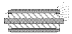
- FIG. 1 is a schematic cross-sectional view perpendicular to the axis showing a self-heating type fixing roller according to an embodiment of the present invention.
- FIG. 2 is a schematic axial sectional view of the self-heating type fixing roller of FIG.
- FIG. 3 is a schematic cross-sectional view showing a main part of a fixing device using the self-heating type fixing roller of FIG.
- the self-heating type fixing roller includes a cylindrical cored bar, a heat insulating layer stacked on the outer peripheral side of the cored bar, and is stacked on the outer peripheral side of the heat insulating layer and heated by power feeding.
- a self-heating type fixing roller comprising a heat generating layer and a release layer laminated on the outer peripheral side of the heat generating layer.
- the self-heating type fixing roller includes a heat generating layer heated by power feeding as described above, it is not necessary to use a heater, and the toner is heated by itself to generate heat through the release layer. The toner can be fixed on the surface.
- the self-heating type fixing roller does not require a heater, the structure is simple and the manufacture is easy. Further, the self-heating type fixing roller is excellent in durability because the laminated layers rotate as a unit and the release layer is not easily worn away.
- the heat insulation layer preferably has a matrix mainly composed of synthetic resin or rubber and a plurality of pores contained in the matrix.
- the heat insulating layer has a matrix mainly composed of synthetic resin or rubber and a plurality of pores contained in the matrix, so that the heat insulating layer is superior in heat insulating properties, and the heat of the heat generating layer is the core. It is possible to suppress loss due to conduction to the gold side.
- the heat generating layer may have a matrix mainly composed of synthetic resin or rubber and a plurality of conductive fillers contained in the matrix.
- the heat generating layer can have appropriate electrical resistance and elasticity by having a matrix mainly composed of a synthetic resin or rubber and a plurality of conductive fillers contained in the matrix, thereby generating heat. It is easy to form a nip while having properties.
- the conductive filler is preferably a mixture of metal powder and carbon powder.
- the electrical resistance can be easily adjusted.
- the heat generating layer may further include an insulating filler in the matrix.
- the electrical resistance can be easily adjusted by the heat generating layer further including an insulating filler in the matrix.
- the conductive filler is preferably needle-shaped. Thus, adjustment of electrical resistance becomes easy by the conductive filler being acicular.
- the electrical resistance between both ends of the heat generating layer is preferably 5 ⁇ or more and 100 ⁇ or less.
- a heat generation amount preferable for fixing a toner image can be obtained using a power supply device having a general configuration.
- the release layer preferably contains a fluororesin as a main component.
- the release layer when the release layer contains a fluororesin as a main component, the release layer has excellent release properties, flexibility, and heat resistance.
- An elastic layer may be further provided between the heat generating layer and the release layer.
- the deformation amount of the release layer is increased while suppressing the deformation amount of the heat generating layer and preventing the heat generating layer from tearing. Nip formation can be facilitated.
- the “columnar shape” is a concept including a so-called cylindrical shape having a hollow in the center.
- the “main component” is a component having the largest content, for example, a component having a content of 50% by mass or more.
- “Needle shape” means a shape having an aspect ratio (filler diameter to length ratio) of 1.5 or more, preferably 2 or more.
- the cross-sectional shape of the filler is not limited to a circle, and when the cross-section of the filler is not a circle, the aspect ratio is obtained with the maximum length of the cross-section as the diameter.
- the self-heating type fixing roller 1 includes a cylindrical cored bar 2, a heat insulating layer 3 directly stacked on the outer periphery of the cored bar 2, and a layered outer peripheral side of the heat insulating layer.
- the heating layer 4 is heated by power feeding, and the release layer 5 is directly laminated on the outer periphery of the heating layer.
- the self-heating type fixing roller 1 further includes a primer layer 6 between the heat insulating layer 3 and the heat generating layer 4.
- the self-heating type fixing roller 1 has an axial length of the release layer 5 smaller than an axial length of the heat generating layer 4, and an outer peripheral surface of the heat generating layer 4 at both ends in the axial direction. Is exposed.
- the self-heating type fixing roller 1 further includes a pair of cylindrical equipotential electrodes 7 formed of a conductor so as to be in contact with inner peripheral surfaces of both end portions of the heat generating layer 4.
- the cored bar 2 extends in the axial direction at the center of the self-heating type fixing roller 1.
- the core 2 may be hollow or solid.
- the metal core 2 can be made of a metal such as aluminum, aluminum alloy, iron or stainless steel, or a heat resistant resin such as polyimide or polyamide.
- a heat resistant resin such as polyimide or polyamide.
- a polyimide having excellent moldability and excellent heat resistance and mechanical strength is preferable.
- the average outer diameter of the cored bar 2 can be, for example, 5 mm or more and 40 mm or less. Moreover, when the cored bar 2 is hollow, the average thickness of the cored bar 2 can be, for example, 10 ⁇ m or more and 40 mm or less. The axial length of the cored bar 2 can be, for example, 100 mm or more and 500 mm or less.
- the heat insulating layer 3 suppresses the heat generated by the heat generating layer 4 from escaping to the cored bar 2 side, and improves the energy efficiency of the self-heating type fixing roller 1.
- the heat insulating layer 3 preferably has a matrix mainly composed of a synthetic resin or rubber and a plurality of pores contained in the matrix. Furthermore, it is preferable that this heat insulation layer 3 has elasticity.
- the rubber used as the main component of the matrix of the heat insulating layer 3 is not particularly limited as long as it has heat resistance, but preferably has elasticity, and rubber (heat resistant rubber) having excellent heat resistance is particularly preferable.
- rubber heat resistant rubber
- silicone rubber, fluoro rubber, or a mixture thereof can be suitably used.
- silicone rubber examples include dimethyl silicone rubber, fluorosilicone rubber, and methylphenyl silicone rubber.
- fluororubber include vinylidene fluoride rubber, tetrafluoroethylene-propylene rubber, tetrafluoroethylene-perfluoromethyl vinyl ether rubber, and the like.
- the synthetic resin examples include phenol resin (PF), epoxy resin (EP), melamine resin (MF), urea resin (urea resin, UF), unsaturated polyester resin (UP), alkyd resin, polyurethane (PUR). ), Thermosetting polyimide (PI), polyethylene (PE), high density polyethylene (HDPE), medium density polyethylene (MDPE), low density polyethylene (LDPE), polypropylene (PP), polyvinyl chloride (PVC), polychlorinated Vinylidene, polystyrene (PS), polyvinyl acetate (PVAc), acrylonitrile butadiene styrene resin (ABS), acrylonitrile styrene resin (AS), polymethyl methacrylate (PMMA), polyamide (PA), polyacetal (POM), polycarbonate (PC) Modified polyphenylene ether (m-PPE), polybutylene terephthalate (PBT), polyethylene terephthalate (PET), and cyclic polyole
- the pores in the matrix of the heat insulating layer 3 can be formed by a foaming agent, a hollow filler or the like.
- the hollow filler examples include organic microballoons and hollow glass beads.
- the foaming agent it decomposes by heating to generate, for example, nitrogen gas, carbon dioxide gas, carbon monoxide, ammonia gas, etc., and an organic foaming agent or an inorganic foaming agent can be used.
- organic blowing agent examples include azo blowing agents such as azodicarbonamide (A.D.C.A) and azobisisobutyronitrile (A.I.B.N), such as dinitrosopentamethylenetetramine (D P.T), N, N′dinitroso-N, N′-dimethylterephthalamide (DNDMTA), and the like, for example, P-toluenesulfonyl hydrazide (TS H), P, P-oxybisbenzenesulfonyl hydrazide (O.B.S.H), benzenesulfonyl hydrazide (B.S.H), and other hydrazides, and trihydrazinotriazine (T.H. T), acetone-P-sulfonylhydrazone and the like are exemplified, and these can be used alone or in combination of two or more.
- azo blowing agents such as azodicarbonamide (A
- Examples of the inorganic foaming agent include sodium bicarbonate, ammonium carbonate, ammonium bicarbonate, sodium borohydride, sodium boron hydride, silicon oxyhydride and the like.
- an inorganic foaming agent has a slower gas generation rate than an organic foaming agent, and adjustment of gas generation is difficult. Therefore, an organic foaming agent is preferable as the chemical foaming agent.
- the organic microballoon is a kind of hollow microsphere (Microsphere), for example, a thermosetting resin such as phenol resin, a thermoplastic resin such as polyvinylidene chloride, and a hollow formed by an organic polymer material such as rubber.
- the spherical fine particles When the heat insulation layer 3 contains an organic microballoon, the flexibility, heat resistance and dimensional stability of the heat insulation layer 3 are improved. Since this organic microballoon has a spherical shape, stress anisotropy hardly occurs even if it is included in the composition forming the heat insulating layer 3. Therefore, the organic microballoon is difficult to reduce the hardness and the heat insulation uniformity of the heat insulating layer 3.
- the heat resistance of the heat insulation layer 3 improves more by using the heat resistant organic microballoon containing thermosetting resins, such as a phenol resin, as an organic microballoon.
- thermosetting resins such as a phenol resin
- a commercial item can be used as said organic microballoon.
- the average diameter of the organic microballoon is usually from several ⁇ m to several hundred ⁇ m, and preferably from 5 ⁇ m to 200 ⁇ m.
- the upper limit of the porosity of the heat insulating layer 3 is preferably 60%, more preferably 50%, and even more preferably 45%.
- the lower limit of the porosity of the heat insulating layer 3 is preferably 5%, more preferably 10%, and even more preferably 15%.
- the porosity is a value measured as an area ratio when a cross section is observed with a microscope.
- the upper limit of the average thickness of the heat insulating layer 3 is preferably 50 mm, and more preferably 20 mm.
- the lower limit of the average thickness is preferably 20 ⁇ m, and more preferably 100 ⁇ m.
- the heat insulating layer 3 and the heat generating layer 4 are joined directly or via another layer. As described above, the heat insulating layer 3 and the heat generating layer 4 are joined, so that wear due to friction with the heat insulating layer 3 on the inner peripheral surface (surface on the core metal 2 side) of the heat generating layer 4 or other layers can be prevented. The durability of the self-heating type fixing roller 1 is improved. In this embodiment, the heat insulation layer 3 and the heat generating layer 4 are joined by laminating a primer layer 6 described later between the heat insulating layer 3 and the heat generating layer 4.
- the heat generating layer 4 is a layer that generates heat due to resistance loss (Joule loss) when power is supplied from both ends exposed from the release layer 5.
- the heat generating layer 4 may be any material that can flow current and generate heat due to resistance loss.
- the heat generating layer 4 includes a matrix mainly composed of synthetic resin or rubber, and a plurality of conductive fillers included in the matrix. It is supposed to have.
- the main component of the matrix of the heat generating layer 4 is a synthetic resin or rubber having heat resistance, and among them, a heat resistant resin is preferable.
- a heat resistant resin examples include polyimide and polyamide, and polyimide having excellent heat resistance and mechanical strength is particularly preferable.
- the heat resistant rubber silicone rubber, fluororubber, or a mixture thereof can be used.
- an insulating filler may be included in the matrix of the heat generating layer 4.
- the electrical contact between the conductive fillers is limited, and the electrical resistance of the heat generating layer 4 can be adjusted relatively easily.
- any material having an insulating property may be used, but titanium oxide, metal silicon, magnesium oxide, magnesium carbonate, magnesium hydroxide, silicon oxide, alumina, boron nitride, which has high thermal conductivity, An inorganic filler such as aluminum nitride is preferably used.
- the conductive filler known materials can be used, and examples thereof include metal powders such as gold and nickel, resin particles subjected to metal plating, such as carbon powders such as carbon black and carbon nanotubes.
- the conductive filler preferably contains carbon powder, and more preferably a mixture of metal powder and carbon powder.
- the metal powder is preferably nickel powder.
- the upper limit of the ratio of the carbon powder in the conductive filler of the heat generating layer 4 is preferably 97% by volume, and more preferably 95% by volume.
- the lower limit of the proportion of the carbon powder in the conductive filler of the heat generating layer 4 is preferably 30% by volume, and more preferably 50% by volume.
- the ratio of the carbon powder in the conductive filler of the heat generating layer 4 is less than the lower limit, the electric resistance of the heat generating layer 4 is greatly decreased by the conductive filler, and the electric resistance of the heat generating layer 4 may not be easily adjusted. There is.
- the conductive filler in the heat generating layer 4 is preferably needle-shaped.
- the electrical resistivity of the heat generating layer 4 is reduced in the direction of orientation of the conductive filler and increased in the direction perpendicular to the direction of orientation of the conductive filler. Can do.
- the electrical resistivity in the axial direction of the heat generating layer 4 can be made smaller than the electrical resistivity in the circumferential direction. In this way, since the current flows stably in the axial direction, the thermal characteristics are stabilized.
- the lower limit of the aspect ratio of the conductive filler is preferably 1.5, and more preferably 2.0.
- the upper limit of the aspect ratio of the conductive filler is preferably 1000, and more preferably 100.
- the aspect ratio of the conductive filler is less than the above lower limit, there is a possibility that a difference in electrical resistivity cannot be provided between the axial direction and the circumferential direction.
- the aspect ratio of the conductive filler exceeds the above upper limit, the heating layer 4 may not be easily applied.
- Examples of the acicular carbon powder include carbon nanotubes (hereinafter sometimes referred to as “CNT”).
- CNT is nano-sized cylindrical carbon.
- CNTs generally have a specific gravity of about 2.0 and an aspect ratio (a ratio of length to diameter) of 50 or more and 1000 or less.
- an aspect ratio a ratio of length to diameter
- the multi-layered CNT has a structure in which cylindrical carbon materials are overlapped in a concentric manner.
- a method for producing CNT a known method can be used. However, a vapor phase growth method that can easily control the diameter of CNT and is excellent in mass productivity is preferable.
- the upper limit of the average diameter of CNT is preferably 500 nm, and more preferably 300 nm.
- the lower limit of the average diameter is preferably 100 nm.
- the average diameter exceeds the said upper limit, there exists a possibility that the softness
- the average diameter is less than the lower limit, the dispersibility of CNTs may be reduced and the mechanical strength of the heat generating layer 4 may be reduced, or the productivity of CNTs may be reduced.
- the average diameter of CNT is the average value of the short axis diameter of CNT measured by observation with a laser scattering method or a scanning electron microscope, for example.
- the upper limit of the average length of CNT is preferably 50 ⁇ m, more preferably 30 ⁇ m, and even more preferably 20 ⁇ m.
- the lower limit of the average length is preferably 1 ⁇ m.
- the average length exceeds the above upper limit, the dispersibility of CNTs may be reduced, the mechanical strength of the heat generating layer 4 may be reduced, and the surface smoothness of the heat generating layer 4 may be reduced.
- the average length is less than the lower limit, the mechanical strength such as elongation at break of the heat generating layer 4 may be insufficient.
- the average length of CNT is the average value of the length of CNT measured, for example by observation with a laser scattering method or a scanning electron microscope.
- the carbon powder having a shape other than the needle shape for example, shell-like carbon particles can be used.
- shell-like carbon particles By using such shell-like carbon particles, the change in electric resistance of the heat generating layer 4 with respect to the added amount becomes gentle, and the electric resistance of the heat generating layer 4 can be easily adjusted.
- the needle-shaped metal powder is not particularly limited, and examples thereof include needle-shaped nickel powder.
- the upper limit of the conductive filler content in the heat generating layer 4 is preferably 60% by volume, more preferably 55% by volume, and even more preferably 50% by volume. On the other hand, as a minimum of the above-mentioned content, 5 volume% is preferred, 10 volume% is more preferred, and 15 volume% is still more preferred.
- the said content exceeds the said upper limit, there exists a possibility that the heat resistance of the heat generating layer 4, mechanical strength, etc. may fall. On the contrary, when the content is less than the lower limit, the resistance of the heat generating layer 4 may be difficult to be within a desired range.
- the upper limit of the average thickness of the heat generating layer 4 is preferably 300 ⁇ m, more preferably 250 ⁇ m, and even more preferably 200 ⁇ m.
- the lower limit of the average thickness is preferably 5 ⁇ m, more preferably 10 ⁇ m, and even more preferably 30 ⁇ m.
- the average thickness exceeds the upper limit, the manufacturing cost of the self-heating type fixing roller 1 may increase.
- the heat generating layer 4 may be easily damaged by heat or impact.
- the upper limit of the electrical resistance between both ends of the heat generating layer 4 is preferably 100 ⁇ , more preferably 80 ⁇ , and even more preferably 60 ⁇ .
- the lower limit of the electrical resistance between both ends of the heat generating layer 4 is preferably 5 ⁇ , more preferably 7.5 ⁇ , and even more preferably 10 ⁇ .
- the upper limit of the electrical resistance (length resistivity) per unit length in the axial direction of the heat generating layer 4 is preferably 1000 ⁇ / m, more preferably 800 ⁇ / m, and further preferably 600 ⁇ / m.
- the lower limit of the length resistivity is preferably 0.01 ⁇ / m, more preferably 0.1 ⁇ / m, and even more preferably 1 ⁇ / m.
- an electrode plate, a brush, etc. (not shown) is brought into contact with the outer peripheral surfaces of the exposed portions at both ends of the heat generating layer 4 is employed.
- An electrode made of a tubular conductor may be disposed on the outer peripheral surface of the heat generating layer 4, and an electrode plate, a brush, or the like may be brought into contact with the terminal.
- the release layer 5 is a layer that is directly laminated on the outer peripheral surface of the heat insulating layer 3 and is in contact with the toner. This release layer 5 prevents toner from adhering to the self-heating type fixing roller 1.
- thermoplastic resin examples include vinyl resin, polyester, polyolefin, acrylic resin, fluorine resin, epoxy resin, phenol resin, urea resin, and the like. Among these, a fluororesin excellent in releasability, flexibility and heat resistance is preferable. These resins may be used alone or in combination of two or more.
- fluororesin examples include polytetrafluoroethylene (PTFE), tetrafluoroethylene-perfluoroalkyl vinyl ether copolymer (PFA), and tetrafluoroethylene-hexafluoropropylene copolymer (FEP).
- PTFE polytetrafluoroethylene
- PFA tetrafluoroethylene-perfluoroalkyl vinyl ether copolymer
- FEP tetrafluoroethylene-hexafluoropropylene copolymer
- the release layer 5 may contain an additive such as a heat conductive filler.
- an additive such as a heat conductive filler.
- heat conductive filler examples include metals, ceramics, boron nitride, carbon nanotubes, alumina, silicon carbide and the like.
- the release layer 5 preferably has an insulating property.
- the lower limit of the electrical resistance per unit length in the axial direction of the release layer 5 is preferably 10 14 ⁇ / m. If the length resistivity of the release layer 5 is less than the above lower limit, the heat generation layer 4 may leak through the release layer 5 and the heat generation of the heat generation layer 4 may be insufficient. This may cause
- the upper limit of the average thickness of the release layer 5 is preferably 50 ⁇ m and more preferably 35 ⁇ m.
- the lower limit of the average thickness is preferably 1 ⁇ m and more preferably 5 ⁇ m.
- the average thickness exceeds the upper limit, the size of the self-heating type fixing roller 1 may increase unnecessarily, or the thermal efficiency of the self-heating type fixing roller 1 may decrease.
- the average thickness is less than the lower limit, the strength of the release layer 5 may be insufficient.
- the release layer 5 may be bonded to the heat generating layer 4 or may be rotated independently without being bonded, but is preferably bonded. As described above, the release layer 5 and the heat generating layer 4 are bonded to each other so that wear due to friction between the inner peripheral surface of the release layer 5 (the surface on the side in contact with the heat generating layer 4) and the heat generating layer 4 can be prevented. The durability of the self-heating type fixing roller 1 is improved.
- the bonding method of the release layer 5 and the heat generating layer 4 is not particularly limited. The bonding method is performed simultaneously with the formation of the release layer 5 or the heat generating layer 4, and the bonding is performed after the release layer 5 and the heat generating layer 4 are formed. Methods and the like. In addition to these methods, the release layer 5 and the heat generating layer 4 can be bonded more firmly by combining the main components of the release layer 5 and the heat generating layer 4 with a high affinity.
- a method of bonding simultaneously with the formation of the release layer 5 or the heat generation layer 4 for example, a method of forming the heat generation layer 4 by applying the heat generation layer 4 to the inner peripheral surface of the release layer 5, extrusion molding, Examples thereof include a method of forming the release layer 5 by applying the release layer 5 to the outer peripheral surface of the layer 4 and performing extrusion molding, and a method of co-extrusion of the release layer 5 and the heat generating layer 4.
- a method of bonding after forming the release layer 5 and the heat generating layer 4 for example, a method of bonding the release layer 5 and the heat generating layer 4 with an adhesive, a side of the release layer 5 on which the heat generating layer 4 is laminated.
- the primer layer 6 is a layer laminated between the heat insulating layer 3 and the heat generating layer 4, and improves the adhesion between the heat insulating layer 3 and the heat generating layer 4.
- the main component of the primer layer 6 can be appropriately selected according to the main components of the heat insulating layer 3 and the heat generating layer 4.
- silicone rubber, fluorine resin, or the like can be used as a specific main component of the primer layer 6, for example, silicone rubber, fluorine resin, or the like can be used.
- compositions for forming the primer layer 6 a commercially available general-purpose product can be used.
- Such compositions include, for example, “X-33-174” from Shin-Etsu Chemical, “KE-1880” from Shin-Etsu Chemical, “DY39-051” from Toray Dow Corning, “PJ992CL” from DuPont Mitsui, Examples include “GLP103SR” from Daikin Industries.
- the upper limit of the average thickness of the primer layer 6 is preferably 30 ⁇ m and more preferably 20 ⁇ m.
- the lower limit of the average thickness is preferably 1 ⁇ m and more preferably 5 ⁇ m.
- the average thickness exceeds the upper limit, the manufacturing cost of the self-heating type fixing roller 1 may increase.
- the average thickness is less than the lower limit, the adhesion between the heat insulating layer 3 and the heat generating layer 4 may be difficult to improve.
- the equipotential electrode 7 equalizes the voltage applied to the outer peripheral surfaces of both ends of the heat generating layer 4 in the circumferential direction of the heat generating layer 4. As a result, a current is allowed to flow substantially evenly throughout the heat generating layer 4, and the heat generating layer 4 generates heat without being biased.
- the equipotential electrode 7 may be formed of a conductor having a sufficiently small electric resistance, but can be formed using a metal foil, a conductive paste, or the like.
- a metal foil copper foil is used suitably and the metal tape by which the adhesive agent was apply
- the self-heating type fixing roller 1 includes a step of forming a material constituting the heat generation layer 4 in a film shape, a step of laminating a material constituting the release layer 5 on the surface of the film-like heat generation layer 4, and the heat generation.
- the equipotential electrode disposing step for disposing the primer, the primer layer forming step for forming the primer layer 6 on the inner peripheral surface of the heat generating layer 4, and the core metal 2 are loaded so that the central axis thereof coincides with the central axis of the cavity. It can manufacture easily and reliably by a manufacturing method provided with the heat insulation layer formation process of injection-molding the composition for heat insulation layer formation in a state.
- the self-heating type fixing roller 1 does not include a heater, a process for manufacturing the heater and a process for embedding the heater in the roller are unnecessary.
- the film-like exothermic layer 4 is formed by coating and baking a resin composition obtained by diluting a material constituting the exothermic layer 4 with a solvent onto a base material (release film).
- coating method of the resin composition conventionally known coating methods such as a spin coating method, a spray coating method, a bar coating method, a die coating method, a slit coating method, a roll coating method, and a dip coating method can be used.
- the solvent in the resin composition is volatilized.
- this baking temperature it can be 100 degreeC or more and 500 degrees C or less, for example.
- the release layer 5 is laminated on the surface of the film-like heat generating layer 4.
- a method of laminating the release layer 5 a method in which the resin composition for forming the release layer 5 is applied and baked on the surface of the heat generating layer 4, or the release layer 5 previously formed in a film shape is attached with an adhesive or the like. A matching method or the like can be used.
- plasma treatment, primer treatment, or the like may be performed on the adhesive surface of the film-like release layer 5 to the heat generation layer 4.
- ⁇ Laminate loading process> In the laminate loading step, a mold having a cylindrical cavity is used, and the laminate of the heat generating layer 4 and the release layer 5 is loaded into the mold so as to form a tube shape along the inner peripheral surface of the mold.
- Examples of the main component of the mold include iron, stainless steel, aluminum, and alloys thereof.
- the smoothing treatment include forming the mold by drawing when the main component of the mold is aluminum, and performing chromium plating, nickel plating, or the like on the mold when the other metal is used.
- the surface roughness (Rz) of the inner peripheral surface of the mold is preferably 20 ⁇ m or less, and more preferably 5 ⁇ m or less.
- the inner diameter of the cavity can be adjusted as appropriate according to the diameter of the self-heating type fixing roller 1.
- the upper limit of the value of (D1-D2) / D1 when the inner diameter of the cavity is D1 and the outer diameter of the tubular release layer 5 is D2 is preferably 10%, more preferably 8%.
- the lower limit of the value of (D1-D2) / D1 is preferably 3%, more preferably 4%. If the value of (D1-D2) / D1 exceeds the upper limit, wrinkles may occur on the outer peripheral surface of the tubular release layer 5 and the uniformity of the nip pressure of the self-heating type fixing roller 1 may be reduced. is there.
- the tube-shaped release layer 5 is preferably longer than the mold.
- the tubular release layer 5 is made longer than the mold, when the tubular release layer 5 is loaded into the mold, both ends of the tubular release layer 5 are removed from the mold. It can be made to project, and this projecting part can be folded back to the outside of both ends of the mold. Thereby, even when the outer diameter of the tubular release layer 5 is smaller than the inner diameter of the mold, the airtightness of the space between the mold and the tubular release layer 5 can be easily and reliably maintained. .
- the average length of the folded portion (the shorter distance of the distance from the folded position to the end of the release layer 5) is 10 mm or more and 30 mm or less. preferable.
- the average length of the folded portion is less than the lower limit, there is a possibility that the effect by the above folding cannot be obtained sufficiently.
- the average length of the folded portion exceeds the above upper limit, the length of the tubular release layer 5 is wasted.
- a mold having a cylindrical cavity is first prepared, and the inner peripheral surface of the mold is cleaned by air wiping or the like to remove adhering foreign matter. Thereafter, the tubular release layer 5 is inserted into the mold, and the diameters at both ends are enlarged. The enlarged portion is folded outside the mold to form a folded portion.
- a vacuum line is connected to the gap formed between the tubular release layer 5 and the inner peripheral surface of the mold, and vacuum suction is performed to adsorb the tubular release layer 5 to the inner peripheral surface of the mold. .
- the fixture is attached to both ends of the mold, and the folded portion is brought into close contact with the outer peripheral surface of the mold.
- equipotential electrodes are formed on the inner peripheral surfaces of both end portions of the heat generating layer 4 by applying and baking a conductive paste, for example.
- the primer layer 6 is formed by coating and drying the primer layer forming composition on the inner peripheral surface of the heat generating layer 4.
- the primer layer forming composition include a composition containing the resin, inorganic filler, and the like exemplified in the primer layer 6.
- the primer layer-forming composition is dried by rotating the mold and the laminate of the release layer 5, the heat generating layer 4, and the primer layer-forming composition around the central axis of the mold under vacuum. Can be done.
- the core metal 2 is inserted into the hollow portion of the laminate of the release layer 5, the heat generating layer 4 and the primer layer 6 so that the central axis of the mold and the central axis of the core metal 2 are substantially coincided with each other, Thereafter, the heat insulation layer 3 is formed by injecting the composition for forming the heat insulation layer between the primer layer 6 and the core metal 2 and vulcanizing.
- the core metal 2 can be manufactured by a known method.
- heat-resistant resin is used as a material for forming the core metal 2
- a resin is applied to the outer peripheral surface of a drum-shaped mold, heated while rotating the mold, and the mold is released to release a hollow cylindrical shape.
- the cored bar 2 can be formed easily and reliably.
- composition for forming a heat insulating layer examples include a composition containing the resin exemplified in the heat insulating layer 3.
- a mold lid is placed on both ends of the mold, and the heat insulating layer forming composition is vulcanized by heating at a predetermined temperature for a predetermined time to form the heat insulating layer 3. Thereafter, by releasing the vacuum between the mold and the tubular release layer 5, the laminate of the core metal 2, the heat insulating layer 3, the primer layer 6, the heat generating layer 4 and the release layer 5 is demolded. A self-heating type fixing roller 1 is obtained.
- further vulcanization may be performed after the above demolding.
- further vulcanization after demolding can reduce the solidification failure of the heat insulating layer 3 due to insufficient vulcanization of the heat insulating layer 3 and the residual volatile components in the heat insulating layer 3.
- the self-heating type fixing roller 1 includes the heat generating layer 4 heated by power feeding as described above, it is not necessary to use a heater, and the toner is heated by itself to heat the toner via the release layer 5. The toner can be fixed on the transfer object.
- the self-heating type fixing roller 1 does not require a heater, the structure is simple and the manufacture is easy. Further, the self-heating type fixing roller 1 is excellent in durability because the laminated layers rotate integrally, so that the release layer 5 is hardly worn out.
- the heat insulating layer 3 has a matrix mainly composed of synthetic resin or rubber and a plurality of pores included in the matrix, the heat insulating layer 3 is more excellent in heat insulating properties.
- the heat of the heat generating layer 4 can be suppressed from being conducted to the cored bar 2 and being lost.
- the heat generating layer 4 includes a matrix mainly composed of synthetic resin or rubber, and a plurality of conductive fillers included in the matrix, so that appropriate electric resistance and elasticity can be obtained. It is easy to form a nip while having exothermic properties.
- the self-heating type fixing roller 1 can stably set the electric resistance of the heat generating layer 4 to a preferable value when the material of the conductive filler of the heat generating layer 4 is metal or carbon.
- the conductive filler since the conductive filler has a needle shape, it is easier to adjust the electric resistance.
- the conductive filler is a mixture of metal powder and carbon powder, the electrical resistance can be adjusted more easily.
- the self-heating type fixing roller 1 includes a pair of cylindrical equipotential electrodes 7 that are in contact with the inner peripheral surfaces of both end portions of the heat generating layer 4, so that a current flows evenly throughout the heat generating layer 4. It is possible to generate heat.
- the fixing device shown in FIG. 3 is a fixing device used in an electrophotographic image forming apparatus, and includes a self-heating type fixing roller 1 as a fixing roller and a pressure arranged in pairs with the self-heating type fixing roller 1. A roller 11 is provided.
- the fixing device fixes the unfixed toner B by heating and pressing the transfer material A on which the unfixed toner B is laminated on the surface by the self-heating fixing roller 1 and the pressure roller 11. Is formed.
- the fixing device provided with the self-heating type fixing roller 1 as a fixing roller can be manufactured at low cost because the structure of the self-heating type fixing roller 1 is simple, excellent in durability, and easily manufactured.
- the self-heating type fixing roller may further include an elastic layer between the heat generating layer and the release layer.
- an elastic layer between the heat generation layer and the release layer By further providing an elastic layer between the heat generation layer and the release layer, the deformation amount of the release layer is increased while suppressing the deformation amount of the heat generation layer and preventing the heat generation layer from tearing. Nip formation can be facilitated.
- the heat insulating layer can be made non-elastic by providing an elastic layer between the heat generating layer and the release layer.
- a layer having a rubber-based matrix and a plurality of pores contained in the matrix is preferable.
- rubber having excellent heat resistance is particularly preferable.
- silicone rubber, fluoro rubber, or a mixture thereof can be suitably used.
- the thickness of the elastic layer formed between the heat generation layer and the release layer is set so that an appropriate nip can be formed in consideration of elasticity and the like.
- examples of the method for joining the heat insulating layer and the heat generating layer include the same methods as those exemplified as the method for joining the release layer and the heat generating layer.
- a primer layer may be provided between the equipotential electrode and the heat insulating layer.
- a primer layer may be laminated between the heat generating layer and the release layer.
- the bonding strength between the heat generating layer and the release layer can be improved.
- an equipotential electrode is not essential.
- a core metal is disposed on the inner periphery of the heat generating layer and filled with a heat insulating layer.
- a method of laminating a release layer on the outer peripheral surface may be used.
- the laminate of the heat generating layer and the release layer may be formed by forming a film-like release layer and coating the film-like release layer with a resin composition that forms the heat-generating layer.
- a resin composition containing a matrix resin, a solvent for dissolving the matrix, and a conductive filler is applied and baked to generate heat with an axial length of 232 mm, an outer peripheral diameter of 56 mm, and an average thickness of 57 ⁇ m.
- Produced a layer prototype As shown in Table 1, with respect to different formulations 1 to 14 of the matrix and the conductive filler, a prototype of the heat generation layer in which the resin composition was applied in the direction perpendicular to the axial direction (circumferential direction), and the resin composition in the axial direction Prototypes of heat generation layers coated in parallel were produced.
- conductive filler As the conductive filler in the resin compositions of Formulations 1 to 14, one or more of carbon nanotubes and acicular nickel were used.
- carbon nanotube carbon fiber “VGCF-H” (average diameter 200 nm, average length 6 ⁇ m) of Showa Denko was used.
- acicular nickel nickel powder “Type 255” (average length of 2.2 to 2.8 ⁇ m) manufactured by the Carbone method of Vale was used.
- the blending amount of the conductive filler in each blending 1 to 14 is as shown in Table 1. In the table, “-” means that the filler is not blended.
- the formulations 1, 4 and 8 to 14 are calorific values that can be used as fixing rollers for fixing devices regardless of the coating direction. Can be obtained. However, the heat resistance using the resin compositions of Formulations 2 and 3 is too high, and the heat resistance of the heat generation layers using the resin compositions of Formulations 5 to 7 is too low. It is considered difficult to obtain an appropriate amount of heat generation using a power supply device used for a normal heating roller.
- the heat generation layer formed by coating perpendicularly to the axial direction has a higher electrical resistance between both ends than the heat generation layer formed by coating parallel to the axial direction.
- the tendency to become was confirmed. This is considered to be due to the electrical resistance in the coating direction being reduced when the needle-like conductive filler is oriented in the coating direction during coating. More specifically, the larger the compounding ratio of the carbon nanotubes having a larger aspect ratio, the greater the difference in electrical resistance between vertical coating and parallel coating.
- the self-heating type fixing roller since the self-heating type fixing roller has a simple structure, excellent durability, and can be easily manufactured, it can be suitably used as a fixing roller of a fixing device for an image forming apparatus.
Landscapes
- Physics & Mathematics (AREA)
- General Physics & Mathematics (AREA)
- Engineering & Computer Science (AREA)
- General Engineering & Computer Science (AREA)
- Mechanical Engineering (AREA)
- Fixing For Electrophotography (AREA)
- Rolls And Other Rotary Bodies (AREA)
- Surface Heating Bodies (AREA)
- Control Of Resistance Heating (AREA)
Abstract
構造が簡潔であり、耐久性に優れ、容易に製造できる自己発熱型定着ローラを提供することを目的とする。本発明の一態様に係る自己発熱型定着ローラは、円柱状の芯金と、この芯金の外周側に積層される断熱層と、この断熱層の外周側に積層され、給電により加熱される発熱層と、この発熱層の外周側に積層される離型層とを備える自己発熱型定着ローラである。上記断熱層が、合成樹脂又はゴムを主成分とするマトリックスと、このマトリックス中に含まれる複数の気孔とを有するとよい。上記発熱層が、合成樹脂又はゴムを主成分とするマトリックスと、このマトリックス中に含まれる複数の導電フィラーとを有するとよい。
Description
本発明は、自己発熱型定着ローラに関する。
複写機、レーザービームプリンタ等の画像形成装置において、印刷及び複写の最終段階では一般に熱定着方式が採用されている。この熱定着方式は、ヒータを内部に設けた加熱ローラと加圧ローラとの間にトナー画像が転写された印刷用紙等の被転写物を通過させることで、未定着のトナーを加熱溶融し、被転写物にトナーを定着させて画像を形成する方式である。
上記従来の加熱ローラとしては、例えば特開2002-31972号公報に記載のものが挙げられる。この加熱ローラでは、ローラの軸方向にヒータが埋設され、このローラ及びヒータの外面側に耐熱性フィルムが配設される。このヒータにより耐熱性フィルムが加熱され、加熱された耐熱性フィルムがローラと独立して回転することでトナーが加熱される。
しかしながら、上記従来の加熱ローラは、内部にヒータを配設することから、構造が複雑であり、製造工程が煩雑となるという不都合がある。また、耐熱性フィルムの内周面側がローラ及びヒータと擦れ合うため耐久性に劣るという不都合もある。
本発明は、上述のような事情に基づいてなされたものであり、構造が簡潔であり、耐久性に優れ、容易に製造できる自己発熱型定着ローラを提供することを目的とする。
本発明の一態様に係る自己発熱型定着ローラは、円柱状の芯金と、この芯金の外周側に積層される断熱層と、この断熱層の外周側に積層され、給電により加熱される発熱層と、この発熱層の外周側に積層される離型層とを備える自己発熱型定着ローラである。
当該自己発熱型定着ローラは、構造が簡潔であり、耐久性に優れ、容易に製造できる。
[本発明の実施形態の説明]
本発明の一態様に係る自己発熱型定着ローラは、円柱状の芯金と、この芯金の外周側に積層される断熱層と、この断熱層の外周側に積層され、給電により加熱される発熱層と、この発熱層の外周側に積層される離型層とを備える自己発熱型定着ローラである。
本発明の一態様に係る自己発熱型定着ローラは、円柱状の芯金と、この芯金の外周側に積層される断熱層と、この断熱層の外周側に積層され、給電により加熱される発熱層と、この発熱層の外周側に積層される離型層とを備える自己発熱型定着ローラである。
当該自己発熱型定着ローラは、上述のように給電により加熱される発熱層を備えるため、ヒータを用いる必要がなく、自ら発熱することにより、離型層を介してトナーを加熱して被転写物にトナーを定着できる。このように当該自己発熱型定着ローラはヒータを必要としないため、構造が簡潔であり、製造も容易である。さらに、当該自己発熱型定着ローラは、積層された各層が一体で回転するため、離型層が摩滅し難く耐久性に優れる。
上記断熱層が、合成樹脂又はゴムを主成分とするマトリックスと、このマトリックス中に含まれる複数の気孔とを有するとよい。このように、上記断熱層が、合成樹脂又はゴムを主成分とするマトリックスと、このマトリックス中に含まれる複数の気孔とを有することによって、断熱層が断熱性により優れ、発熱層の熱が芯金側に伝導して損失となることを抑制することができる。
上記発熱層が、合成樹脂又はゴムを主成分とするマトリックスと、このマトリックス中に含まれる複数の導電フィラーとを有するとよい。このように、上記発熱層が、合成樹脂又はゴムを主成分とするマトリックスと、このマトリックス中に含まれる複数の導電フィラーとを有することによって、適切な電気抵抗及び弾性を有することができ、発熱性を有しながらニップの形成が容易となる。
上記導電フィラーが金属粉末と炭素粉末との混合体であるとよい。このように、上記導電フィラーが金属粉末と炭素粉末との混合体であることによって、電気抵抗の調節が容易となる。
上記発熱層が上記マトリックス中に絶縁フィラーをさらに含んでもよい。このように、上記発熱層が上記マトリックス中に絶縁フィラーをさらに含むことによっても、電気抵抗の調節が容易となる。
上記導電フィラーが針状であるとよい。このように、導電フィラーが針状であることによって、電気抵抗の調節が容易となる。
上記発熱層の両端間の電気抵抗としては、5Ω以上100Ω以下が好ましい。このように、上記発熱層の両端間の電気抵抗が上記範囲内であることによって、一般的な構成の電源装置を用いてトナー画像の定着に好ましい発熱量を得ることができる。
上記離型層がフッ素樹脂を主成分とするとよい。このように、上記離型層がフッ素樹脂を主成分とすることによって、離型層が離型性、可撓性及び耐熱性に優れるものとなる。
上記発熱層の両端部に当接する一対の円筒状の等電位電極をさらに備えるとよい。このように、上記発熱層の両端部に当接する一対の円筒状の等電位電極をさらに備えることによって、発熱層全体を偏りなく発熱させられる。
上記発熱層と離型層との間に弾性層をさらに備えるとよい。このように、上記発熱層と離型層との間に弾性層をさらに備えることによって、発熱層の変形量を抑制して発熱層の断裂を防止しながら、離型層の変形量を大きくしてニップの形成を容易化できる。
なお、「円柱状」とは、中央に空洞を有する所謂円筒状も含む概念である。「主成分」とは、最も含有量が多い成分であり、例えば含有量が50質量%以上の成分をいう。また、「針状」とは、アスペクト比(フィラーの径と長さの比)が1.5以上、好ましくは2以上である形状を意味する。フィラーの断面形状は円に限らず、フィラーの断面が円でない場合は断面の最大長さを径としてアスペクト比を求める。
[本発明の実施形態の詳細]
以下、本発明の実施形態に係る自己発熱型定着ローラについて図面を参照しつつ詳説する。
以下、本発明の実施形態に係る自己発熱型定着ローラについて図面を参照しつつ詳説する。
[自己発熱型定着ローラ]
当該自己発熱型定着ローラ1は、図1及び図2に示すように円柱状の芯金2と、この芯金2の外周に直接積層される断熱層3と、この断熱層の外周側に積層され、給電により加熱される発熱層4と、この発熱層の外周に直接積層される離型層5とを備える。また、当該自己発熱型定着ローラ1は、断熱層3と発熱層4との間にプライマー層6をさらに備える。
当該自己発熱型定着ローラ1は、図1及び図2に示すように円柱状の芯金2と、この芯金2の外周に直接積層される断熱層3と、この断熱層の外周側に積層され、給電により加熱される発熱層4と、この発熱層の外周に直接積層される離型層5とを備える。また、当該自己発熱型定着ローラ1は、断熱層3と発熱層4との間にプライマー層6をさらに備える。
また、当該自己発熱型定着ローラ1は、図2に示すように、離型層5の軸方向長さが発熱層4の軸方向長さよりも小さく、軸方向両端部において発熱層4の外周面が露出している。また、当該自己発熱型定着ローラ1は、発熱層4の両端部の内周面に当接するよう導電体で形成される一対の円筒状の等電位電極7をさらに備える。
<芯金>
芯金2は、当該自己発熱型定着ローラ1の中心において軸方向に延伸する。この芯金2は中空でもよく、中実でもよい。
芯金2は、当該自己発熱型定着ローラ1の中心において軸方向に延伸する。この芯金2は中空でもよく、中実でもよい。
芯金2には、アルミニウム、アルミニウム合金、鉄、ステンレス等の金属、又はポリイミド、ポリアミド等の耐熱性樹脂などを用いることができる。耐熱性樹脂の中では、成形性に優れ、耐熱性及び機械的強度に優れるポリイミドが好ましい。
芯金2の平均外径としては、例えば5mm以上40mm以下とすることができる。また、芯金2が中空の場合、芯金2の平均厚みとしては、例えば10μm以上40mm以下とすることができる。芯金2の軸方向長さとしては、例えば100mm以上500mm以下とすることができる。
<断熱層>
断熱層3は、発熱層4が発生する熱が芯金2側に逃げることを抑制し、当該自己発熱型定着ローラ1のエネルギー効率を向上する。この断熱層3は、合成樹脂又はゴムを主成分とするマトリックスと、このマトリックス中に含まれる複数の気孔とを有することが好ましい。さらに、この断熱層3は、弾性を有することが好ましい。
断熱層3は、発熱層4が発生する熱が芯金2側に逃げることを抑制し、当該自己発熱型定着ローラ1のエネルギー効率を向上する。この断熱層3は、合成樹脂又はゴムを主成分とするマトリックスと、このマトリックス中に含まれる複数の気孔とを有することが好ましい。さらに、この断熱層3は、弾性を有することが好ましい。
断熱層3のマトリックスの主成分とされるゴムとしては耐熱性を有するものであれば特に限定されないが、弾性を有することが好ましく、耐熱性に優れるゴム(耐熱性ゴム)が特に好ましい。この耐熱性ゴムとしては、シリコーンゴム、フッ素ゴム、或いはこれらの混合物を好適に用いることができる。
上記シリコーンゴムとしては、例えばジメチルシリコーンゴム、フルオロシリコーンゴム、メチルフェニルシリコーンゴム等が挙げられる。上記フッ素ゴムとしては、例えばフッ化ビニリデンゴム、テトラフルオロエチレン-プロピレンゴム、テトラフルオロエチレン-パーフルオロメチルビニルエーテルゴム等が挙げられる。
また、前記合成樹脂としては、例えばフェノール樹脂(PF)、エポキシ樹脂(EP)、メラミン樹脂(MF)、尿素樹脂(ユリア樹脂、UF)、不飽和ポリエステル樹脂(UP)、アルキド樹脂、ポリウレタン(PUR)、熱硬化性ポリイミド(PI)、ポリエチレン(PE)、高密度ポリエチレン(HDPE)、中密度ポリエチレン(MDPE)、低密度ポリエチレン(LDPE)、ポリプロピレン(PP)、ポリ塩化ビニル(PVC)、ポリ塩化ビニリデン、ポリスチレン(PS)、ポリ酢酸ビニル(PVAc)、アクリロニトリルブタジエンスチレン樹脂(ABS)、アクリロニトリルスチレン樹脂(AS)、ポリメチルメタクリレート(PMMA)、ポリアミド(PA)、ポリアセタール(POM)、ポリカーボネート(PC)、変性ポリフェニレンエーテル(m-PPE)、ポリブチレンテレフタレート(PBT)、ポリエチレンテレフタレート(PET)、環状ポリオレフィン(COP)等が挙げられる。
また、断熱層3のマトリックス中の気孔は、発泡剤、中空フィラー等によって形成することができる。中空フィラーとしては、例えば有機マイクロバルーン、中空ガラスビーズ等を使用することができる。
上記発泡剤としては、加熱することにより分解して、例えば窒素ガス、炭酸ガス、一酸化炭素、アンモニアガス等を発生するものであり、有機発泡剤又は無機発泡剤が使用できる。
有機発泡剤としては、例えばアゾジカルボンアミド(A.D.C.A)、アゾビスイソブチロニトリル(A.I.B.N)等のアゾ系発泡剤、例えばジニトロソペンタメチレンテトラミン(D.P.T)、N,N’ジニトロソ-N,N’-ジメチルテレフタルアミド(D.N.D.M.T.A)等のニトロソ系発泡剤、例えばP-トルエンスルホニルヒドラジド(T.S.H)、P,P-オキシビスベンゼンスルホニルヒドラジド(O.B.S.H)、ベンゼンスルホニルヒドラジド(B.S.H)等のヒドラジド系、他にはトリヒドラジノトリアジン(T.H.T)、アセトン-P-スルホニルヒドラゾンなどが例示され、これらを単独で、又は二種類以上合わせて使用できる。
また、無機発泡剤としては、例えば重炭酸ナトリウム、炭酸アンモニウム、重炭酸アンモニウム、ホウ化水素ナトリウム、ソジウムボロンハイドライド、シリコンオキシハイドライド等が例示される。一般的に無機発泡剤は、ガス発生速度が有機発泡剤より緩慢でありガス発生の調整が難しい。そのため、化学発泡剤としては、有機発泡剤が好ましい。
上記有機マイクロバルーンとは、中空マイクロスフィア(Microsphere)の1種であり、例えばフェノール樹脂等の熱硬化性樹脂、ポリ塩化ビニリデン等の熱可塑性樹脂、ゴムなどの有機高分子材料で形成された中空の球状微粒子である。断熱層3が有機マイクロバルーンを含有することで、断熱層3の柔軟性、耐熱性及び寸法安定性が向上する。この有機マイクロバルーンは球状であるため、断熱層3を形成する組成物に含有させても応力の異方性が生じ難い。従って、有機マイクロバルーンは断熱層3の硬度及び断熱性の均一性を低下させ難い。また、有機マイクロバルーンとしてフェノール樹脂等の熱硬化性樹脂を含有する耐熱性有機マイクロバルーンを用いることで、断熱層3の耐熱性がより向上する。なお、上記有機マイクロバルーンとしては市販品を用いることができる。
上記有機マイクロバルーンの平均径は、通常数μm以上数百μm以下であり、5μm以上200μm以下が好ましい。
断熱層3の気孔率の上限としては、60%が好ましく、50%がより好ましく、45%がさらに好ましい。一方、断熱層3の気孔率の下限としては、5%が好ましく、10%がより好ましく、15%がさらに好ましい。断熱層3の気孔率が上記上限を超える場合、断熱層3の強度が不十分となるおそれがある。逆に、断熱層3の気孔率が上記下限に満たない場合、断熱層3の断熱性が不十分となるおそれがある。なお、気孔率とは、断面を顕微鏡観察した際の面積率として測定される値である。
断熱層3の平均厚みの上限としては、50mmが好ましく、20mmがより好ましい。一方、上記平均厚みの下限としては、20μmが好ましく、100μmがより好ましい。上記平均厚みが上記上限を超える場合、当該自己発熱型定着ローラ1の大きさが不必要に増加するおそれがある。逆に、上記平均厚みが上記下限に満たない場合、断熱層3の断熱性が不十分となり、当該自己発熱型定着ローラ1のエネルギー効率が低くなるおそれがある。
断熱層3と発熱層4とは直接又は他の層を介して接合されていることが好ましい。このように、断熱層3と発熱層4とが接合されることで、発熱層4の内周面(芯金2側の面)の断熱層3又は他の層との摩擦による摩耗が防止でき、当該自己発熱型定着ローラ1の耐久性が向上する。本実施形態では、断熱層3と発熱層4との間に後述するプライマー層6を積層することで断熱層3と発熱層4とを接合している。
<発熱層>
発熱層4は、離型層5から露出する両端部から給電されることにより、抵抗損(ジュール損)によって発熱する層である。
発熱層4は、離型層5から露出する両端部から給電されることにより、抵抗損(ジュール損)によって発熱する層である。
発熱層4は、電流を流すことができ、抵抗損によって発熱するものであればよいが、好ましくは、合成樹脂又はゴムを主成分とするマトリックスと、このマトリックス中に含まれる複数の導電フィラーとを有するものとされる。
発熱層4のマトリックスの主成分としては、耐熱性を有する合成樹脂又はゴムが挙げられ、中でも、耐熱性樹脂が好ましい。この耐熱性樹脂としては、例えばポリイミド、ポリアミド等が挙げられ、耐熱性及び機械的強度に優れるポリイミドが特に好ましい。また、耐熱性ゴムとしては、シリコーンゴム、フッ素ゴム、又はこれらの混合物を用いることができる。
発熱層4のマトリックス中には、絶縁フィラーを含んでもよい。絶縁フィラーを含むことにより、導電フィラー間の電気的接触を制限して、発熱層4の電気抵抗を比較的容易に調節することができる。
このような絶縁フィラーの材質としては、絶縁性を有するものであればよいが、熱伝導率が大きい酸化チタン、金属ケイ素、酸化マグネシウム、炭酸マグネシウム、水酸化マグネシウム、酸化ケイ素、アルミナ、窒化ホウ素、窒化アルミニウム等の無機フィラーが好適に使用される。
上記導電フィラーとしては、公知のものを使用でき、例えば金、ニッケル等の金属粉末、金属メッキを施した樹脂粒子、例えばカーボンブラック、カーボンナノチューブ等の炭素粉末などが挙げられる。これらの中でも、耐熱性及び導電率の観点から、導電フィラーが炭素粉末を含むことが好ましく、金属粉末と炭素粉末との混合体であることがより好ましい。金属粉末としてはニッケル粉末が好ましい。
導電フィラーが金属粉末と炭素粉末との混合体である場合、発熱層4の導電フィラー中の炭素粉末の割合の上限としては、97体積%が好ましく、95体積%がより好ましい。
一方、発熱層4の導電フィラー中の炭素粉末の割合の下限としては、30体積%が好ましく、50体積%がより好ましい。発熱層4の導電フィラー中の炭素粉末の割合が上記上限を超える場合、金属粉末が均等に分散せず、発熱層4の電気抵抗を均一にすることが容易でなくなるおそれがある。逆に、発熱層4の導電フィラー中の炭素粉末の割合が上記下限に満たない場合、導電フィラーによる発熱層4の電気抵抗の低下が大きく、発熱層4の電気抵抗の調整が容易でなくなるおそれがある。
一方、発熱層4の導電フィラー中の炭素粉末の割合の下限としては、30体積%が好ましく、50体積%がより好ましい。発熱層4の導電フィラー中の炭素粉末の割合が上記上限を超える場合、金属粉末が均等に分散せず、発熱層4の電気抵抗を均一にすることが容易でなくなるおそれがある。逆に、発熱層4の導電フィラー中の炭素粉末の割合が上記下限に満たない場合、導電フィラーによる発熱層4の電気抵抗の低下が大きく、発熱層4の電気抵抗の調整が容易でなくなるおそれがある。
また、発熱層4中の導電フィラーは、針状であることが好ましい。導電フィラーが針状であることによって、導電フィラーに配向性を持たせることで、発熱層4の電気抵抗率を導電フィラーの配向方向に小さく、導電フィラーの配向方向に垂直な方向に大きくすることができる。これにより、発熱層4の軸方向の電気抵抗率を周方向の電気抵抗率よりも小さくすることができる。このようにすると軸方向に安定して電流が流れるため、熱特性が安定する。
導電フィラーのアスペクト比の下限としては、1.5が好ましく、2.0がより好ましい。一方、導電フィラーのアスペクト比の上限としては、1000が好ましく、100がより好ましい。導電フィラーのアスペクト比が上記下限に満たない場合、軸方向と周方向とで電気抵抗率の差を設けることができないおそれがある。逆に、導電フィラーのアスペクト比が上記上限を超える場合、発熱層4の塗工が容易ではなくなるおそれがある。
針状の炭素粉末としては、カーボンナノチューブ(以下、「CNT」と呼称することがある)が挙げられる。CNTは、ナノサイズの円筒状カーボンである。CNTは、一般に比重が約2.0、アスペクト比(直径に対する長さの比)が50以上1000以下である。また、CNTとしては、単層型(single-wall)と複層型(multi-wall)とが代表的である。上記複層型CNTは、筒状のカーボン材料が同心円状に幾重にも重なった構造を有する。CNTの製法は、公知の方法を用いることができるが、CNTの直径を制御しやすく、量産性にも優れた気相成長法が好ましい。
CNTの平均直径の上限としては、500nmが好ましく、300nmがより好ましい。一方、上記平均直径の下限としては、100nmが好ましい。上記平均直径が上記上限を超える場合、発熱層4の柔軟性や表面の平滑性が低下するおそれがある。逆に、上記平均直径が上記下限に満たない場合、CNTの分散性が低下して発熱層4の機械的強度が低下するおそれや、CNTの生産性が低下するおそれがある。なお、CNTの平均直径とは、例えばレーザー散乱法や走査型電子顕微鏡による観察によって測定したCNTの短軸径の平均値である。
CNTの平均長さの上限としては、50μmが好ましく、30μmがより好ましく、20μmがさらに好ましい。一方、上記平均長さの下限としては、1μmが好ましい。上記平均長さが上記上限を超える場合、CNTの分散性が低下し発熱層4の機械的強度が低下するおそれや、発熱層4の表面の平滑性が低下するおそれがある。逆に、上記平均長さが上記下限に満たない場合、発熱層4の破断伸び等の機械的強度が不十分となるおそれがある。なお、CNTの平均長さとは、例えばレーザー散乱法や走査型電子顕微鏡による観察によって測定したCNTの長さの平均値である。
また、針状以外の形状を有する炭素粉末としては、例えばシェル状のカーボン粒子を用いることができる。このようなシェル状のカーボン粒子を用いることで、添加量に対する発熱層4の電気抵抗変化が穏やかとなり、発熱層4の電気抵抗の調節が容易となる。
また、針状の金属粉末としては、特に限定されないが、例えば針状ニッケル粉末等が挙げられる。
発熱層4における導電フィラーの含有量の上限としては、60体積%が好ましく、55体積%がより好ましく、50体積%がさらに好ましい。一方、上記含有量の下限としては、5体積%が好ましく、10体積%がより好ましく、15体積%がさらに好ましい。上記含有量が上記上限を超える場合、発熱層4の耐熱性、機械的強度等が低下するおそれがある。逆に、上記含有量が上記下限に満たない場合、発熱層4の抵抗を所望の範囲とし難くなるおそれがある。
発熱層4の平均厚みの上限としては、300μmが好ましく、250μmがより好ましく、200μmがさらに好ましい。一方、上記平均厚みの下限としては、5μmが好ましく、10μmがより好ましく、30μmがさらに好ましい。上記平均厚みが上記上限を超える場合、当該自己発熱型定着ローラ1の製造コストが増加するおそれがある。一方、上記平均厚みが上記下限に満たない場合、発熱層4が熱や衝撃により破損し易くなるおそれがある。
発熱層4の両端間の電気抵抗の上限としては、100Ωが好ましく、80Ωがより好ましく、60Ωがさらに好ましい。一方、発熱層4の両端間の電気抵抗の下限としては、5Ωが好ましく、7.5Ωがより好ましく、10Ωがさらに好ましい。上記抵抗が上記上限を超える場合、発熱層4の温度上昇に必要な電圧が大きくなり、当該自己発熱型定着ローラ1を駆動するための電源装置が不必要に高価となるおそれがある。逆に、上記抵抗が上記下限に満たない場合、発熱層4の温度上昇に必要な電流が大きくなり、やはり当該自己発熱型定着ローラ1を駆動するための電源装置が不必要に高価となるおそれがある。
また、発熱層4の軸方向の単位長さあたりの電気抵抗(長さ抵抗率)の上限としては、1000Ω/mが好ましく、800Ω/mがより好ましく、600Ω/mがさらに好ましい。一方、上記長さ抵抗率の下限としては、0.01Ω/mが好ましく、0.1Ω/mがより好ましく、1Ω/mがさらに好ましい。上記長さ抵抗率が上記上限を超える場合、発熱層4の電気抵抗が大きくなり過ぎるおそれがある。逆に、上記長さ抵抗率が上記下限に満たない場合、発熱層4の電気抵抗が小さくなり過ぎるおそれがある。
発熱層4に電流を印加する方法としては、図示しない電極板、ブラシ等を発熱層4の両端の露出部分の外周面に当接させる方法が採用される。発熱層4の外周面に管状の導電体からなる電極を配設し、この端子に電極板、ブラシ等を当接させてもよい。
<離型層>
離型層5は、断熱層3の外周面に直接積層され、トナーと接触する層である。この離型層5は、トナーが自己発熱型定着ローラ1に付着することを防止する。
離型層5は、断熱層3の外周面に直接積層され、トナーと接触する層である。この離型層5は、トナーが自己発熱型定着ローラ1に付着することを防止する。
離型層5の主成分としては、例えば熱可塑性樹脂及び熱硬化性樹脂を用いることができる。上記熱可塑性樹脂としては、例えばビニル樹脂、ポリエステル、ポリオレフィン、アクリル樹脂、フッ素樹脂、エポキシ樹脂、フェノール樹脂、尿素樹脂等が挙げられる。これらの中で、離型性、可撓性及び耐熱性に優れるフッ素樹脂が好ましい。また、これらの樹脂を単独で用いてもよく、2種以上混合して用いてもよい。
上記フッ素樹脂としては、例えばポリテトラフルオロエチレン(PTFE)、テトラフルオロエチレン-パーフルオロアルキルビニルエーテル共重合体(PFA)、テトラフルオロエチレン-ヘキサフルオロプロピレン共重合体(FEP)等が挙げられる。これらの中で、分子量が小さく離型性に優れるPFA又はPTFEが好ましい。
離型層5は、熱伝導フィラー等の添加剤を含有してもよい。離型層5が熱伝導フィラーを含有することで、発熱層4の熱を効率よくトナーに伝えることができる。
上記熱伝導フィラーとしては、例えば金属、セラミック、ボロンナイトライド、カーボンナノチューブ、アルミナ、シリコンカーバイド等が挙げられる。
離型層5は、絶縁性を有することが好ましい。具体的には、離型層5の軸方向の単位長さあたりの電気抵抗の下限としては、1014Ω/mが好ましい。離型層5の上記長さ抵抗率が上記下限に満たない場合、発熱層4から離型層5を介して漏電し、発熱層4の発熱が不十分となるおそや、感電事故又は装置故障の原因となるおそれがある。
離型層5の平均厚みの上限としては、50μmが好ましく、35μmがより好ましい。
一方、上記平均厚みの下限としては、1μmが好ましく、5μmがより好ましい。上記平均厚みが上記上限を超える場合、当該自己発熱型定着ローラ1の大きさが不必要に増大するおそれや、当該自己発熱型定着ローラ1の熱効率が低下するおそれがある。逆に、上記平均厚みが上記下限に満たない場合、離型層5の強度が不十分となるおそれがある。
一方、上記平均厚みの下限としては、1μmが好ましく、5μmがより好ましい。上記平均厚みが上記上限を超える場合、当該自己発熱型定着ローラ1の大きさが不必要に増大するおそれや、当該自己発熱型定着ローラ1の熱効率が低下するおそれがある。逆に、上記平均厚みが上記下限に満たない場合、離型層5の強度が不十分となるおそれがある。
離型層5は発熱層4と接合されていてもよく、接合されず独立して回転できるものでもよいが、接合されていることが好ましい。このように、離型層5と発熱層4とが接合されることで、離型層5の内周面(発熱層4と接する側の面)の発熱層4との摩擦による摩耗が防止でき、当該自己発熱型定着ローラ1の耐久性が向上する。この離型層5と発熱層4の接合方法としては、特に限定されず、離型層5又は発熱層4の形成と同時に接合する方法、離型層5及び発熱層4を形成した後に接合する方法等が挙げられる。また、これらの方法に加え、離型層5及び発熱層4の主成分を親和性の高い組み合わせとすることでより強固に離型層5と発熱層4とを接合できる。
上記離型層5又は発熱層4の形成と同時に接合する方法としては、例えば離型層5の内周面に発熱層4を塗布、押出成形等することで発熱層4を形成する方法、発熱層4の外周面に離型層5を塗布、押出成形等することで離型層5を形成する方法、離型層5と発熱層4とを共押出する方法が挙げられる。
上記離型層5及び発熱層4を形成した後に接合する方法としては、例えば離型層5と発熱層4とを接着剤により接着する方法、離型層5の発熱層4が積層される側の面にプラズマ処理等の表面処理を行う方法、離型層5の主成分がフッ素樹脂である場合に例えば加熱、電離放射線の照射、カップリング剤の塗布等により離型層5と発熱層4とを化学結合させる方法等が挙げられる。
<プライマー層>
プライマー層6は、断熱層3と発熱層4との間に積層される層であり、断熱層3と発熱層4との密着性を向上させる。このプライマー層6の主成分としては、断熱層3と発熱層4との主成分に応じ適宜選択できる。プライマー層6の具体的な主成分としては、例えばシリコーンゴム、フッ素樹脂等を用いることができる。
プライマー層6は、断熱層3と発熱層4との間に積層される層であり、断熱層3と発熱層4との密着性を向上させる。このプライマー層6の主成分としては、断熱層3と発熱層4との主成分に応じ適宜選択できる。プライマー層6の具体的な主成分としては、例えばシリコーンゴム、フッ素樹脂等を用いることができる。
プライマー層6を形成する組成物としては、市販の汎用品を用いることができる。このような組成物としては、例えば信越化学社の「X-33-174」、信越化学社の「KE-1880」、東レダウコーニング社の「DY39-051」、三井デュポン社の「PJ992CL」、ダイキン工業社の「GLP103SR」等が挙げられる。
上記プライマー層6の平均厚みの上限としては、30μmが好ましく、20μmがより好ましい。一方、上記平均厚みの下限としては、1μmが好ましく、5μmがより好ましい。上記平均厚みが上記上限を超える場合、当該自己発熱型定着ローラ1の製造コストが増加するおそれがある。逆に、上記平均厚みが上記下限に満たない場合、断熱層3と発熱層4との密着性が向上し難いおそれがある。
<等電位電極>
等電位電極7は、発熱層4の両端部の外周面に印加される電圧を、発熱層4の周方向に均等化する。これによって、発熱層4の全体に略均等に電流を流し、発熱層4を偏りなく発熱させる。
等電位電極7は、発熱層4の両端部の外周面に印加される電圧を、発熱層4の周方向に均等化する。これによって、発熱層4の全体に略均等に電流を流し、発熱層4を偏りなく発熱させる。
等電位電極7は、十分に電気抵抗が小さい導電体で形成すればよいが、金属箔、導電性ペースト等を用いて形成することができる。上記金属箔としては、銅箔が好適に用いられ、金属箔に接着剤が塗布された金属テープを用いてもよい。
[自己発熱型定着ローラの製造方法]
当該自己発熱型定着ローラ1は、発熱層4を構成する材料をフィルム状に形成する工程と、フィルム状の発熱層4の表面に離型層5を構成する材料を積層する工程と、この発熱層4と離型層5との積層体を、金型の円柱状のキャビティの内周面に沿うよう装填する積層体装填工程と、発熱層4の両端部の内周面に等電位電極7を配設する等電位電極配設工程と、発熱層4の内周面にプライマー層6を形成するプライマー層形成工程と、芯金2をその中心軸がキャビティの中心軸と一致するよう装填した状態で断熱層形成用組成物を射出成形する断熱層形成工程とを備える製造方法により容易かつ確実に製造することができる。
当該自己発熱型定着ローラ1は、発熱層4を構成する材料をフィルム状に形成する工程と、フィルム状の発熱層4の表面に離型層5を構成する材料を積層する工程と、この発熱層4と離型層5との積層体を、金型の円柱状のキャビティの内周面に沿うよう装填する積層体装填工程と、発熱層4の両端部の内周面に等電位電極7を配設する等電位電極配設工程と、発熱層4の内周面にプライマー層6を形成するプライマー層形成工程と、芯金2をその中心軸がキャビティの中心軸と一致するよう装填した状態で断熱層形成用組成物を射出成形する断熱層形成工程とを備える製造方法により容易かつ確実に製造することができる。
当該自己発熱型定着ローラ1はヒータを備えないため、ヒータを製造する工程及びローラにヒータを埋設する工程が不要である。
<フィルム形成工程>
フィルム形成工程では、発熱層4を構成する材料を溶媒で希釈した樹脂組成物の基材(離型フィルム)への塗工及び焼成により、フィルム状の発熱層4を形成する。
フィルム形成工程では、発熱層4を構成する材料を溶媒で希釈した樹脂組成物の基材(離型フィルム)への塗工及び焼成により、フィルム状の発熱層4を形成する。
樹脂組成物の塗工方法としては、スピンコート法、スプレーコート法、バーコート法、ダイコート法、スリットコート法、ロールコート法、ディップコート法等の従来公知の塗工方法を用いることができる。
樹脂組成物の焼成では、樹脂組成物中の溶媒を揮発させる。この焼成温度としては、例えば100℃以上500℃以下とすることができる。
<積層工程>
積層工程では、フィルム状の発熱層4の表面に離型層5を積層する。離型層5の積層方法としては、離型層5を形成する樹脂組成物を発熱層4の表面に塗工及び焼成する方法、予めフィルム状に形成した離型層5を接着剤等で貼り合わせる方法等を用いることができる。発熱層4と離型層5との密着力を向上するために、フィルム状の離型層5の発熱層4に対する接着面にプラズマ処理、プライマー処理等を行ってもよい。
積層工程では、フィルム状の発熱層4の表面に離型層5を積層する。離型層5の積層方法としては、離型層5を形成する樹脂組成物を発熱層4の表面に塗工及び焼成する方法、予めフィルム状に形成した離型層5を接着剤等で貼り合わせる方法等を用いることができる。発熱層4と離型層5との密着力を向上するために、フィルム状の離型層5の発熱層4に対する接着面にプラズマ処理、プライマー処理等を行ってもよい。
<積層体装填工程>
積層体装填工程では、円柱状のキャビティを有する金型を用い、この金型の内周面に沿うチューブ状となるように発熱層4及び離型層5の積層体を金型に装填する。
積層体装填工程では、円柱状のキャビティを有する金型を用い、この金型の内周面に沿うチューブ状となるように発熱層4及び離型層5の積層体を金型に装填する。
金型の主成分としては、例えば鉄、ステンレス、アルミニウム、これらの合金等が挙げられる。
また、金型内周面に平滑化処理を施すことが好ましい。このように、金型内周面に平滑化処理を施すことで、当該自己発熱型定着ローラ1の表面の平滑性が向上するため、ニップ性が向上すると共に、断熱層3形成後に当該自己発熱型定着ローラ1を金型から引き抜く際の脱型性が向上する。この平滑化処理としては、金型の主成分がアルミニウムの場合は引き抜きにより金型を形成すること、また他の金属の場合は金型にクロムメッキ、ニッケルメッキ等を行うことが挙げられる。金型内周面の表面粗さ(Rz)としては、20μm以下が好ましく、5μm以下がより好ましい。
キャビティの内径は当該自己発熱型定着ローラ1の径に応じて適宜調整できる。キャビティの内径をD1、チューブ状の離型層5の外径をD2としたときの(D1-D2)/D1の値の上限としては、10%が好ましく、8%がより好ましい。一方、(D1-D2)/D1の値の下限としては、3%が好ましく、4%がより好ましい。上記(D1-D2)/D1の値が上記上限を超える場合、チューブ状の離型層5の外周面にしわが発生し、当該自己発熱型定着ローラ1のニップ圧の均一性が低下するおそれがある。逆に、上記(D1-D2)/D1の値が上記下限に満たない場合、チューブ状の離型層5を金型の内周面に沿って装填し難くなり、当該自己発熱型定着ローラ1の製造効率が低下するおそれがある。
チューブ状の離型層5としては、金型より長尺のものが好ましい。このようにチューブ状の離型層5を金型より長尺とすることにより、チューブ状の離型層5を金型に装填する際、チューブ状の離型層5の両端部を金型から突出させることができ、この突出部を金型の両端部の外側に折り返すことが可能となる。これにより、金型の内径よりチューブ状の離型層5の外径が細い場合でも、金型とチューブ状の離型層5との間の空間の気密性を容易かつ確実に保つことができる。
チューブ状の離型層5の両端部を折り返す場合、この折り返し部の平均長さ(折り返し位置から離型層5の端部との距離のうち短い方の距離)としては、10mm以上30mm以下が好ましい。折り返し部の平均長さが上記下限に満たない場合、上述の折り返しによる効果が十分に得られないおそれがある。一方、折り返し部の平均長さが上記上限を超える場合、チューブ状の離型層5の長さに無駄が生じる。
本工程では、まず円柱状のキャビティを有する金型を用意し、エア拭き等により金型内周面を清掃し付着している異物を除去する。その後、チューブ状の離型層5を金型に挿入し、両端部の口径を拡大する。この拡大部を金型の外側に折り返して折り返し部を形成する。
その後、チューブ状の離型層5と金型内周面との間に生じた隙間に真空ラインを接続して真空吸引を行い、チューブ状の離型層5を金型内周面に吸着させる。その後、固定具を金型の両端側に装着し、上記折り返し部を金型の外周面に密着させる。
<等電位電極配設工程>
等電位電極配設工程では、発熱層4の両端部の内周面に、例えば導電性ペーストの塗布及び焼成により等電位電極を形成する。
等電位電極配設工程では、発熱層4の両端部の内周面に、例えば導電性ペーストの塗布及び焼成により等電位電極を形成する。
<プライマー層形成工程>
プライマー層形成工程では、発熱層4の内周面にプライマー層形成用組成物を塗装及び乾燥することでプライマー層6を形成する。このプライマー層形成用組成物としては、例えば上記プライマー層6において例示した樹脂、無機フィラー等を含む組成物が挙げられる。プライマー層形成用組成物の乾燥は、真空下で、金型の中心軸を中心として金型並びに離型層5、発熱層4及びプライマー層形成用組成物の積層体を回転させながら加熱することで行うことができる。
プライマー層形成工程では、発熱層4の内周面にプライマー層形成用組成物を塗装及び乾燥することでプライマー層6を形成する。このプライマー層形成用組成物としては、例えば上記プライマー層6において例示した樹脂、無機フィラー等を含む組成物が挙げられる。プライマー層形成用組成物の乾燥は、真空下で、金型の中心軸を中心として金型並びに離型層5、発熱層4及びプライマー層形成用組成物の積層体を回転させながら加熱することで行うことができる。
<断熱層形成工程>
断熱層形成工程では、金型の中心軸と芯金2の中心軸が略一致するように芯金2を離型層5、発熱層4及びプライマー層6の積層体の中空部に挿入し、その後断熱層形成用組成物をプライマー層6と芯金2との間に注入し加硫することで断熱層3を形成する。
断熱層形成工程では、金型の中心軸と芯金2の中心軸が略一致するように芯金2を離型層5、発熱層4及びプライマー層6の積層体の中空部に挿入し、その後断熱層形成用組成物をプライマー層6と芯金2との間に注入し加硫することで断熱層3を形成する。
上記芯金2は公知の方法で製造することができる。芯金2の形成材料として耐熱性樹脂を用いる場合、例えばドラム状の金型の外周面に樹脂を塗布し、金型を回転させながら加熱し、金型を離型することで中空円柱状の芯金2を容易かつ確実に形成できる。
上記断熱層形成用組成物としては、例えば上記断熱層3において例示した樹脂等を含む組成物が挙げられる。
断熱層形成用組成物注入後、金型蓋を金型の両端に被せ、断熱層形成用組成物を所定温度で所定時間加熱することにより加硫し断熱層3を形成する。その後、金型とチューブ状の離型層5間の真空を開放することで芯金2、断熱層3、プライマー層6、発熱層4及び離型層5の積層体を脱型することで当該自己発熱型定着ローラ1が得られる。
なお、上記脱型後さらに加硫を行うとよい。このように、脱型後にさらに加硫を行うことで、断熱層3の加硫不足による断熱層3の固化不良や断熱層3内への揮発成分の残留を低減できる。
<利点>
当該自己発熱型定着ローラ1は、上述のように給電により加熱される発熱層4を備えるため、ヒータを用いる必要がなく、自ら発熱することにより、離型層5を介してトナーを加熱して被転写物にトナーを定着できる。このように、当該自己発熱型定着ローラ1は、ヒータを必要としないため、構造が簡潔であり、製造も容易である。さらに、当該自己発熱型定着ローラ1は、積層された各層が一体で回転するため、離型層5が摩滅し難く耐久性に優れる。
当該自己発熱型定着ローラ1は、上述のように給電により加熱される発熱層4を備えるため、ヒータを用いる必要がなく、自ら発熱することにより、離型層5を介してトナーを加熱して被転写物にトナーを定着できる。このように、当該自己発熱型定着ローラ1は、ヒータを必要としないため、構造が簡潔であり、製造も容易である。さらに、当該自己発熱型定着ローラ1は、積層された各層が一体で回転するため、離型層5が摩滅し難く耐久性に優れる。
また、当該自己発熱型定着ローラ1は、断熱層3が、合成樹脂又はゴムを主成分とするマトリックスと、このマトリックス中に含まれる複数の気孔とを有するため、断熱層3が断熱性により優れ、発熱層4の熱が芯金2側に伝導して損失となることを抑制することができる。
また、当該自己発熱型定着ローラ1は、発熱層4が、合成樹脂又はゴムを主成分とするマトリックスと、このマトリックス中に含まれる複数の導電フィラーとを有することによって、適切な電気抵抗及び弾性を有することができ、発熱性を有しながらニップの形成が容易である。
また、当該自己発熱型定着ローラ1は、発熱層4の導電フィラーの素材が金属又は炭素であることによって、発熱層4の電気抵抗を安定して好ましい値とすることができる。また、導電フィラーが針状であることによって、電気抵抗の調節がよりに容易である。また、導電フィラーが金属粉末と炭素粉末との混合体であることによって、電気抵抗の調節がさらに容易である。
また、当該自己発熱型定着ローラ1は、発熱層4の両端部の内周面に当接する一対の円筒状の等電位電極7を備えることによって、発熱層4全体に均等に電流を流して偏りなく発熱させられる。
[定着装置]
図3の定着装置は、電子写真方式の画像形成装置に用いられる定着装置であり、定着ローラとしての当該自己発熱型定着ローラ1、及び当該自己発熱型定着ローラ1と対で配置される加圧ローラ11を備える。この定着装置は、未定着トナーBが表面に積層された被転写材Aを当該自己発熱型定着ローラ1及び加圧ローラ11で加熱及び加圧することで未定着トナーBを定着させ、定着トナーCを形成するものである。
図3の定着装置は、電子写真方式の画像形成装置に用いられる定着装置であり、定着ローラとしての当該自己発熱型定着ローラ1、及び当該自己発熱型定着ローラ1と対で配置される加圧ローラ11を備える。この定着装置は、未定着トナーBが表面に積層された被転写材Aを当該自己発熱型定着ローラ1及び加圧ローラ11で加熱及び加圧することで未定着トナーBを定着させ、定着トナーCを形成するものである。
当該自己発熱型定着ローラ1を定着ローラとして備えた定着装置は、当該自己発熱型定着ローラ1の構造が簡潔であり、耐久性に優れ、容易に製造できるため、低いコストで製造できる。
[その他の実施形態]
今回開示された実施の形態は全ての点で例示であって制限的なものではないと考えられるべきである。本発明の範囲は、上記実施形態の構成に限定されるものではなく、特許請求の範囲によって示され、特許請求の範囲と均等の意味及び範囲内での全ての変更が含まれることが意図される。
今回開示された実施の形態は全ての点で例示であって制限的なものではないと考えられるべきである。本発明の範囲は、上記実施形態の構成に限定されるものではなく、特許請求の範囲によって示され、特許請求の範囲と均等の意味及び範囲内での全ての変更が含まれることが意図される。
当該自己発熱型定着ローラは、発熱層と離型層との間に弾性層をさらに備えてもよい。
このように、発熱層と離型層との間に弾性層をさらに備えることによって、発熱層の変形量を抑制して発熱層の断裂を防止しながら、離型層の変形量を大きくしてニップの形成を容易化できる。また、発熱層と離型層との間に弾性層を設けることによって断熱層を弾性を有しないものとすることもできる。
このように、発熱層と離型層との間に弾性層をさらに備えることによって、発熱層の変形量を抑制して発熱層の断裂を防止しながら、離型層の変形量を大きくしてニップの形成を容易化できる。また、発熱層と離型層との間に弾性層を設けることによって断熱層を弾性を有しないものとすることもできる。
発熱層と離型層との間に形成される弾性層としては、ゴムを主成分とするマトリックスと、このマトリックス中に含まれる複数の気孔とを有するものが好ましい。上記ゴムとしては、耐熱性に優れるゴムが特に好ましい。この耐熱性ゴムとしては、シリコーンゴム、フッ素ゴム、或いはこれらの混合物を好適に用いることができる。
発熱層と離型層との間に形成される弾性層の厚さとしては、弾性等を考慮して、適切なニップを形成できるよう設定される。
上記実施形態では、断熱層と発熱層との間にプライマー層を備えるものを例に取り説明したが、これに限定されず、プライマー層を備えず、断熱層の外周面に発熱層が直接積層されるものであってもよい。この場合、断熱層と発熱層との接合方法としては、例えば上述の離型層と発熱層との接合方法として例示したものと同様の方法が挙げられる。
また、等電位電極と断熱層との間にプライマー層を設けてもよい。
また、発熱層と離型層との間にプライマー層が積層されてもよい。このように、発熱層と離型層との間にプライマー層を積層することで、発熱層と離型層との接合強度を向上できる。
また、当該自己発熱型定着ローラにおいて、等電位電極は必須ではない。
当該自己発熱型定着ローラの製造方法としては、発熱層と離型層との積層体を用いる方法の他、発熱層の内周に芯金を配置して断熱層を充填した後に、発熱層の外周面に離型層を積層する方法としてもよい。
発熱層と離型層との積層体は、フィルム状の離型層を形成し、このフィルム状の離型層に発熱層を形成する樹脂組成物を塗工して形成してもよい。
以下、実施例に基づき本発明を詳述するが、この実施例の記載に基づいて本発明が限定的に解釈されるものではない。
〔試作品〕
マトリックスとなる樹脂と、マトリックスを溶解する溶媒と、導電フィラーとを含む樹脂組成物を塗工及び焼成して、軸方向長さが232mm、外周面の直径が56mm、平均厚さが57μmの発熱層の試作品を製作した。表1に示すように、マトリックス及び導電フィラーの異なる配合1~14について、樹脂組成物を軸方向と垂直方向(周方向)に塗工した発熱層の試作品と、樹脂組成物を軸方向と平行方向に塗工した発熱層の試作品とをそれぞれ製作した。
マトリックスとなる樹脂と、マトリックスを溶解する溶媒と、導電フィラーとを含む樹脂組成物を塗工及び焼成して、軸方向長さが232mm、外周面の直径が56mm、平均厚さが57μmの発熱層の試作品を製作した。表1に示すように、マトリックス及び導電フィラーの異なる配合1~14について、樹脂組成物を軸方向と垂直方向(周方向)に塗工した発熱層の試作品と、樹脂組成物を軸方向と平行方向に塗工した発熱層の試作品とをそれぞれ製作した。
(マトリックス)
配合1~14の発熱層を形成するマトリックスを溶媒で溶解したものとして、2種類のワニスを使用した。具体的には、ワニス1としては、宇部興産社のポリイミドワニス「U-ワニス-S」を使用した。ワニス2としては、IST社のポリイミドワニス「パイヤーML」を使用した。各配合1~14におけるワニスの配合量は、表1に記載するとおりである。
配合1~14の発熱層を形成するマトリックスを溶媒で溶解したものとして、2種類のワニスを使用した。具体的には、ワニス1としては、宇部興産社のポリイミドワニス「U-ワニス-S」を使用した。ワニス2としては、IST社のポリイミドワニス「パイヤーML」を使用した。各配合1~14におけるワニスの配合量は、表1に記載するとおりである。
(導電フィラー)
配合1~14の樹脂組成物中の導電フィラーとしては、カーボンナノチューブ及び針状ニッケルの一種又は複数種を用いた。上記カーボンナノチューブとしては昭和電工社の炭素繊維「VGCF-H」(平均径200nm、平均長さ6μm)を使用した。上記針状ニッケルとしては、ヴァーレ社のカーボニル法により製造されるニッケル粉末「Type255」(平均長さ2.2~2.8μm)を使用した。各配合1~14における導電フィラーの配合量は、表1に記載するとおりである。なお、表中の「-」は、そのフィラーを配合していないことを意味する。
配合1~14の樹脂組成物中の導電フィラーとしては、カーボンナノチューブ及び針状ニッケルの一種又は複数種を用いた。上記カーボンナノチューブとしては昭和電工社の炭素繊維「VGCF-H」(平均径200nm、平均長さ6μm)を使用した。上記針状ニッケルとしては、ヴァーレ社のカーボニル法により製造されるニッケル粉末「Type255」(平均長さ2.2~2.8μm)を使用した。各配合1~14における導電フィラーの配合量は、表1に記載するとおりである。なお、表中の「-」は、そのフィラーを配合していないことを意味する。
(電気抵抗)
上記配合1~14の樹脂組成物で製作した発熱層の試作品について、両端間の電気抵抗の値を測定した。この測定結果を、表1に併せて示す。なお、「>106」は、電気抵抗の値が、この測定に用いたテスターの測定レンジの上限である10MΩを超えていたことを示す。
上記配合1~14の樹脂組成物で製作した発熱層の試作品について、両端間の電気抵抗の値を測定した。この測定結果を、表1に併せて示す。なお、「>106」は、電気抵抗の値が、この測定に用いたテスターの測定レンジの上限である10MΩを超えていたことを示す。

配合1~14の樹脂組成物を用いた発熱層の電気抵抗の値を検討すると、配合1,4,8~14は、塗工方向にかかわらず定着装置用の定着ローラとして利用可能な発熱量を得ることができる。しかしながら、配合2,3の樹脂組成物を用いた発熱層については、電気抵抗が高くなり過ぎ、また、配合5~7の樹脂組成物を用いた発熱層については、電気抵抗が低くなり過ぎるため、通常の加熱ローラに用いられる電源装置を使用して適切な発熱量を得ることは難しいと考えられる。
また、樹脂組成物の配合にかかわらず、軸方向に垂直に塗工して形成した発熱層の方が、軸方向に平行に塗工して形成した発熱層よりも両端間の電気抵抗が大きくなる傾向が確認された。これは、針状の導電フィラーが塗工時に塗工方向に配向することにより、塗工方向の電気抵抗が小さくなることによるものと考えられる。さらに詳しく見ると、アスペクト比がより大きいカーボンナノチューブの配合比率が大きいほど、垂直塗工時と平行塗工時との電気抵抗の差が大きくなった。
以上のように、当該自己発熱型定着ローラは、構造が簡潔であり、耐久性に優れ、容易に製造できるため、画像形成装置用定着装置の定着ローラとして好適に使用できる。
1 自己発熱型定着ローラ
2 芯金
3 断熱層
4 発熱層
5 離型層
6 プライマー層
7 等電位電極
11 加圧ローラ
A 被転写材
B 未定着トナー
C 定着トナー
2 芯金
3 断熱層
4 発熱層
5 離型層
6 プライマー層
7 等電位電極
11 加圧ローラ
A 被転写材
B 未定着トナー
C 定着トナー
Claims (10)
- 円柱状の芯金と、
この芯金の外周側に積層される断熱層と、
この断熱層の外周側に積層され、給電により加熱される発熱層と、
この発熱層の外周側に積層される離型層と
を備える自己発熱型定着ローラ。 - 上記断熱層が、合成樹脂又はゴムを主成分とするマトリックスと、このマトリックス中に含まれる複数の気孔とを有する請求項1に記載の自己発熱型定着ローラ。
- 上記発熱層が、合成樹脂又はゴムを主成分とするマトリックスと、このマトリックス中に含まれる複数の導電フィラーとを有する請求項1又は請求項2に記載の自己発熱型定着ローラ。
- 上記導電フィラーが金属粉末と炭素粉末との混合体である請求項3に記載の自己発熱型定着ローラ。
- 上記発熱層が上記マトリックス中に絶縁フィラーをさらに含む請求項3又は請求項4に記載の自己発熱型定着ローラ。
- 上記導電フィラーが針状である請求項3、請求項4又は請求項5に記載の自己発熱型定着ローラ。
- 上記発熱層の両端間の電気抵抗が5Ω以上100Ω以下である請求項1から請求項6のいずれか1項に記載の自己発熱型定着ローラ。
- 上記離型層がフッ素樹脂を主成分とする請求項1から請求項7のいずれか1項に記載の自己発熱型定着ローラ。
- 上記発熱層の両端部に当接する一対の円筒状の等電位電極をさらに備える請求項1から請求項8のいずれか1項に記載の自己発熱型定着ローラ。
- 上記発熱層と離型層との間に弾性層を備える請求項1から請求項9のいずれか1項に記載の自己発熱型定着ローラ。
Priority Applications (1)
| Application Number | Priority Date | Filing Date | Title |
|---|---|---|---|
| US15/126,586 US20170082957A1 (en) | 2015-01-20 | 2015-11-03 | Self-heat-generating fixing roller |
Applications Claiming Priority (2)
| Application Number | Priority Date | Filing Date | Title |
|---|---|---|---|
| JP2015-008951 | 2015-01-20 | ||
| JP2015008951A JP6475990B2 (ja) | 2015-01-20 | 2015-01-20 | 自己発熱型定着ローラ |
Publications (1)
| Publication Number | Publication Date |
|---|---|
| WO2016117205A1 true WO2016117205A1 (ja) | 2016-07-28 |
Family
ID=56416766
Family Applications (1)
| Application Number | Title | Priority Date | Filing Date |
|---|---|---|---|
| PCT/JP2015/080972 Ceased WO2016117205A1 (ja) | 2015-01-20 | 2015-11-03 | 自己発熱型定着ローラ |
Country Status (3)
| Country | Link |
|---|---|
| US (1) | US20170082957A1 (ja) |
| JP (1) | JP6475990B2 (ja) |
| WO (1) | WO2016117205A1 (ja) |
Cited By (1)
| Publication number | Priority date | Publication date | Assignee | Title |
|---|---|---|---|---|
| JP2017173799A (ja) * | 2017-01-27 | 2017-09-28 | 株式会社金陽社 | 発熱定着ベルト、画像定着装置、および発熱定着ベルトの製造方法 |
Families Citing this family (2)
| Publication number | Priority date | Publication date | Assignee | Title |
|---|---|---|---|---|
| JP6472269B2 (ja) * | 2015-02-23 | 2019-02-20 | キヤノン株式会社 | 電子写真用部材 |
| US10025178B2 (en) * | 2015-03-24 | 2018-07-17 | Research & Business Foundation Sungkyunkwan University | Patterning device |
Citations (4)
| Publication number | Priority date | Publication date | Assignee | Title |
|---|---|---|---|---|
| JPH01134486A (ja) * | 1987-11-20 | 1989-05-26 | Nhk Spring Co Ltd | 電子写真装置の定着装置 |
| JPH01150183A (ja) * | 1987-12-07 | 1989-06-13 | Nhk Spring Co Ltd | 電子写真装置の定着装置 |
| JPH075784A (ja) * | 1993-06-15 | 1995-01-10 | Canon Inc | 加熱装置及び画像形成装置 |
| JP2009109997A (ja) * | 2007-10-12 | 2009-05-21 | Ist Corp | 画像定着装置 |
Family Cites Families (22)
| Publication number | Priority date | Publication date | Assignee | Title |
|---|---|---|---|---|
| US4714819A (en) * | 1985-07-17 | 1987-12-22 | Hitachi Metals, Ltd. | Directly heating fixing apparatus having current collecting bearings |
| US5987296A (en) * | 1997-09-24 | 1999-11-16 | Konica Corporation | Fixing device with heat roller having heating resistor layer therein |
| JP2002049260A (ja) * | 2000-08-02 | 2002-02-15 | Konica Corp | 定着装置 |
| JP2002296941A (ja) * | 2001-03-30 | 2002-10-09 | Canon Inc | 加熱ローラ |
| JP2004279534A (ja) * | 2003-03-13 | 2004-10-07 | Minolta Co Ltd | 定着装置 |
| JP2006202583A (ja) * | 2005-01-20 | 2006-08-03 | Nichias Corp | 加熱ロール及び加熱ロールの製造方法 |
| JP2007178828A (ja) * | 2005-12-28 | 2007-07-12 | Canon Inc | 画像加熱装置 |
| JP2008286899A (ja) * | 2007-05-16 | 2008-11-27 | Murata Mach Ltd | ヒートローラ及びこれを備えた定着装置 |
| US8557345B2 (en) * | 2008-08-26 | 2013-10-15 | Xerox Corporation | Process for making CNT/PFA composite coatings for fuser applications |
| JP2010145665A (ja) * | 2008-12-17 | 2010-07-01 | Canon Inc | 定着装置及び画像形成装置 |
| KR101518735B1 (ko) * | 2009-02-19 | 2015-05-18 | 삼성전자주식회사 | 탄소나노튜브를 채용한 가열 부재 및 이를 채용한 정착장치 |
| KR20100113379A (ko) * | 2009-04-13 | 2010-10-21 | 삼성전자주식회사 | 저항 발열층를 채용한 가열 부재 및 이를 채용한 정착장치 |
| KR101665506B1 (ko) * | 2009-07-14 | 2016-10-13 | 삼성전자 주식회사 | 저항 발열층을 채용한 가열부재 및 이를 채용한 정착장치 |
| KR101705117B1 (ko) * | 2009-10-20 | 2017-02-22 | 에스프린팅솔루션 주식회사 | 저항 발열층을 채용한 가열롤러 및 이를 채용한 정착장치 |
| KR101602417B1 (ko) * | 2009-11-18 | 2016-03-11 | 삼성전자주식회사 | 저항 발열층를 채용한 가열부재 , 이를 채용한 정착장치 및 화상형성장치 |
| JP2011137973A (ja) * | 2009-12-28 | 2011-07-14 | Murata Machinery Ltd | ヒートロール及び画像形成装置 |
| JP5568782B2 (ja) * | 2011-10-24 | 2014-08-13 | コニカミノルタ株式会社 | 定着装置、画像形成装置及び損傷検出方法 |
| EP2680087B1 (en) * | 2012-05-08 | 2014-11-19 | Samsung Electronics Co., Ltd | Heating member and fusing apparatus including the same |
| JP2014048494A (ja) * | 2012-08-31 | 2014-03-17 | Konica Minolta Inc | 定着装置および画像形成装置 |
| KR20140055117A (ko) * | 2012-10-30 | 2014-05-09 | 삼성전자주식회사 | 정착장치와 이를 가지는 화상형성장치 |
| KR101850271B1 (ko) * | 2012-11-06 | 2018-04-19 | 에스프린팅솔루션 주식회사 | 가열 부재 및 이를 채용한 정착 장치 |
| KR102008312B1 (ko) * | 2013-03-26 | 2019-10-21 | 휴렛-팩커드 디벨롭먼트 컴퍼니, 엘.피. | 정착 장치 및 이를 채용한 전자사진방식 화상형성장치 |
-
2015
- 2015-01-20 JP JP2015008951A patent/JP6475990B2/ja active Active
- 2015-11-03 WO PCT/JP2015/080972 patent/WO2016117205A1/ja not_active Ceased
- 2015-11-03 US US15/126,586 patent/US20170082957A1/en not_active Abandoned
Patent Citations (4)
| Publication number | Priority date | Publication date | Assignee | Title |
|---|---|---|---|---|
| JPH01134486A (ja) * | 1987-11-20 | 1989-05-26 | Nhk Spring Co Ltd | 電子写真装置の定着装置 |
| JPH01150183A (ja) * | 1987-12-07 | 1989-06-13 | Nhk Spring Co Ltd | 電子写真装置の定着装置 |
| JPH075784A (ja) * | 1993-06-15 | 1995-01-10 | Canon Inc | 加熱装置及び画像形成装置 |
| JP2009109997A (ja) * | 2007-10-12 | 2009-05-21 | Ist Corp | 画像定着装置 |
Cited By (1)
| Publication number | Priority date | Publication date | Assignee | Title |
|---|---|---|---|---|
| JP2017173799A (ja) * | 2017-01-27 | 2017-09-28 | 株式会社金陽社 | 発熱定着ベルト、画像定着装置、および発熱定着ベルトの製造方法 |
Also Published As
| Publication number | Publication date |
|---|---|
| US20170082957A1 (en) | 2017-03-23 |
| JP6475990B2 (ja) | 2019-02-27 |
| JP2016133673A (ja) | 2016-07-25 |
Similar Documents
| Publication | Publication Date | Title |
|---|---|---|
| JP5017522B2 (ja) | 面状発熱体及びその製造方法 | |
| JP5109168B2 (ja) | 発熱定着ベルト及びその製造方法並びに画像定着装置 | |
| JP4680979B2 (ja) | ポリイミドチューブ、その製造方法、及び定着ベルト | |
| JP4988633B2 (ja) | 定着部材、定着部材の製造方法、定着用回転体、定着装置及び画像形成装置 | |
| JP2010211220A (ja) | 定着装置 | |
| JP6475990B2 (ja) | 自己発熱型定着ローラ | |
| US8787809B2 (en) | Pressure members comprising CNT/PFA nanocomposite coatings | |
| JP2006126595A (ja) | ロールカバー | |
| JP3691044B1 (ja) | 弾性部材、トナー定着部体および定着装置、並びに弾性部材の製造方法 | |
| JP2010170132A (ja) | 定着部材を備える印刷装置 | |
| JP6029361B2 (ja) | フューザー部材を製造する方法 | |
| JP2009109998A (ja) | 発熱定着ロールおよび画像定着装置 | |
| JP4398059B2 (ja) | ゴム被覆ローラ及びその製造方法 | |
| JP5072381B2 (ja) | 定着装置及び画像形成装置 | |
| JP6069518B2 (ja) | 定着ベルト用ポリイミドチューブ | |
| JP6652346B2 (ja) | 自己発熱型定着ローラ | |
| JP6149536B2 (ja) | 定着部材、定着装置、及び画像形成装置 | |
| JP5061255B2 (ja) | 定着部材の製造方法 | |
| JP6045925B2 (ja) | 発熱回転体 | |
| JP2015210524A5 (ja) | 定着アッセンブリ | |
| JP2016045258A (ja) | 画像形成装置用加熱ローラ | |
| JP2017037154A (ja) | 自己発熱型定着ローラ | |
| JP2012225990A (ja) | ポリイミドチューブ及び定着ベルト | |
| WO2018074036A1 (ja) | 自己発熱型定着ローラ及び自己発熱型定着ローラの製造方法 | |
| JP6106305B1 (ja) | 発熱定着ベルトおよびそれを含む画像定着装置 |
Legal Events
| Date | Code | Title | Description |
|---|---|---|---|
| 121 | Ep: the epo has been informed by wipo that ep was designated in this application |
Ref document number: 15878894 Country of ref document: EP Kind code of ref document: A1 |
|
| WWE | Wipo information: entry into national phase |
Ref document number: 15126586 Country of ref document: US |
|
| NENP | Non-entry into the national phase |
Ref country code: DE |
|
| 122 | Ep: pct application non-entry in european phase |
Ref document number: 15878894 Country of ref document: EP Kind code of ref document: A1 |