WO2016114113A1 - 道路形状情報生成装置、道路形状情報集配システム及び道路形状情報生成プログラム - Google Patents
道路形状情報生成装置、道路形状情報集配システム及び道路形状情報生成プログラム Download PDFInfo
- Publication number
- WO2016114113A1 WO2016114113A1 PCT/JP2016/000061 JP2016000061W WO2016114113A1 WO 2016114113 A1 WO2016114113 A1 WO 2016114113A1 JP 2016000061 W JP2016000061 W JP 2016000061W WO 2016114113 A1 WO2016114113 A1 WO 2016114113A1
- Authority
- WO
- WIPO (PCT)
- Prior art keywords
- road shape
- shape information
- road
- vehicle
- sensor value
- Prior art date
- Legal status (The legal status is an assumption and is not a legal conclusion. Google has not performed a legal analysis and makes no representation as to the accuracy of the status listed.)
- Ceased
Links
Images




Classifications
-
- G—PHYSICS
- G08—SIGNALLING
- G08G—TRAFFIC CONTROL SYSTEMS
- G08G1/00—Traffic control systems for road vehicles
- G08G1/16—Anti-collision systems
- G08G1/167—Driving aids for lane monitoring, lane changing, e.g. blind spot detection
-
- G—PHYSICS
- G01—MEASURING; TESTING
- G01C—MEASURING DISTANCES, LEVELS OR BEARINGS; SURVEYING; NAVIGATION; GYROSCOPIC INSTRUMENTS; PHOTOGRAMMETRY OR VIDEOGRAMMETRY
- G01C21/00—Navigation; Navigational instruments not provided for in groups G01C1/00 - G01C19/00
- G01C21/38—Electronic maps specially adapted for navigation; Updating thereof
- G01C21/3804—Creation or updating of map data
- G01C21/3807—Creation or updating of map data characterised by the type of data
- G01C21/3815—Road data
- G01C21/3819—Road shape data, e.g. outline of a route
-
- G—PHYSICS
- G01—MEASURING; TESTING
- G01C—MEASURING DISTANCES, LEVELS OR BEARINGS; SURVEYING; NAVIGATION; GYROSCOPIC INSTRUMENTS; PHOTOGRAMMETRY OR VIDEOGRAMMETRY
- G01C21/00—Navigation; Navigational instruments not provided for in groups G01C1/00 - G01C19/00
- G01C21/38—Electronic maps specially adapted for navigation; Updating thereof
- G01C21/3804—Creation or updating of map data
- G01C21/3833—Creation or updating of map data characterised by the source of data
- G01C21/3837—Data obtained from a single source
-
- G—PHYSICS
- G06—COMPUTING OR CALCULATING; COUNTING
- G06T—IMAGE DATA PROCESSING OR GENERATION, IN GENERAL
- G06T1/00—General purpose image data processing
- G06T1/0007—Image acquisition
-
- G—PHYSICS
- G08—SIGNALLING
- G08G—TRAFFIC CONTROL SYSTEMS
- G08G1/00—Traffic control systems for road vehicles
- G08G1/01—Detecting movement of traffic to be counted or controlled
- G08G1/0104—Measuring and analyzing of parameters relative to traffic conditions
- G08G1/0108—Measuring and analyzing of parameters relative to traffic conditions based on the source of data
- G08G1/0112—Measuring and analyzing of parameters relative to traffic conditions based on the source of data from the vehicle, e.g. floating car data [FCD]
-
- G—PHYSICS
- G08—SIGNALLING
- G08G—TRAFFIC CONTROL SYSTEMS
- G08G1/00—Traffic control systems for road vehicles
- G08G1/01—Detecting movement of traffic to be counted or controlled
- G08G1/0104—Measuring and analyzing of parameters relative to traffic conditions
- G08G1/0125—Traffic data processing
- G08G1/0129—Traffic data processing for creating historical data or processing based on historical data
-
- G—PHYSICS
- G08—SIGNALLING
- G08G—TRAFFIC CONTROL SYSTEMS
- G08G1/00—Traffic control systems for road vehicles
- G08G1/01—Detecting movement of traffic to be counted or controlled
- G08G1/0104—Measuring and analyzing of parameters relative to traffic conditions
- G08G1/0137—Measuring and analyzing of parameters relative to traffic conditions for specific applications
- G08G1/0141—Measuring and analyzing of parameters relative to traffic conditions for specific applications for traffic information dissemination
-
- G—PHYSICS
- G08—SIGNALLING
- G08G—TRAFFIC CONTROL SYSTEMS
- G08G1/00—Traffic control systems for road vehicles
- G08G1/09—Arrangements for giving variable traffic instructions
- G08G1/0962—Arrangements for giving variable traffic instructions having an indicator mounted inside the vehicle, e.g. giving voice messages
- G08G1/0967—Systems involving transmission of highway information, e.g. weather, speed limits
- G08G1/096708—Systems involving transmission of highway information, e.g. weather, speed limits where the received information might be used to generate an automatic action on the vehicle control
- G08G1/096716—Systems involving transmission of highway information, e.g. weather, speed limits where the received information might be used to generate an automatic action on the vehicle control where the received information does not generate an automatic action on the vehicle control
-
- G—PHYSICS
- G08—SIGNALLING
- G08G—TRAFFIC CONTROL SYSTEMS
- G08G1/00—Traffic control systems for road vehicles
- G08G1/09—Arrangements for giving variable traffic instructions
- G08G1/0962—Arrangements for giving variable traffic instructions having an indicator mounted inside the vehicle, e.g. giving voice messages
- G08G1/0967—Systems involving transmission of highway information, e.g. weather, speed limits
- G08G1/096733—Systems involving transmission of highway information, e.g. weather, speed limits where a selection of the information might take place
- G08G1/096758—Systems involving transmission of highway information, e.g. weather, speed limits where a selection of the information might take place where no selection takes place on the transmitted or the received information
-
- G—PHYSICS
- G08—SIGNALLING
- G08G—TRAFFIC CONTROL SYSTEMS
- G08G1/00—Traffic control systems for road vehicles
- G08G1/09—Arrangements for giving variable traffic instructions
- G08G1/0962—Arrangements for giving variable traffic instructions having an indicator mounted inside the vehicle, e.g. giving voice messages
- G08G1/0967—Systems involving transmission of highway information, e.g. weather, speed limits
- G08G1/096766—Systems involving transmission of highway information, e.g. weather, speed limits where the system is characterised by the origin of the information transmission
- G08G1/096775—Systems involving transmission of highway information, e.g. weather, speed limits where the system is characterised by the origin of the information transmission where the origin of the information is a central station
Definitions
- the present disclosure relates to a road shape information generation device, a road shape information collection / delivery system, and a road shape information generation program that generate information related to a road shape.
- Patent Document 1 Even when the moving body is a vehicle (automobile), it is possible to generate information (road shape information) regarding the shape of the road such as an inclination angle and a curve radius by applying Patent Document 1.
- road shape information information regarding the shape of the road such as an inclination angle and a curve radius.
- a means for photographing a vehicle traveling on the road is required, and a means for image processing and analyzing the photographed image data is also required.
- a high-spec CPU and a large-capacity memory are required, resulting in a complicated configuration and high cost.
- An object of the present disclosure is that it is possible to appropriately generate information on the shape of the road without incurring a complicated configuration and high cost in view of the circumstances described above, and effectively use the generated information.
- An object of the present invention is to provide a road shape information generation device, a road shape information collection / delivery system, and a road shape information generation program.
- a road shape information generation device includes a sensor value acquisition unit that acquires a sensor value that acts on a vehicle as the vehicle travels, and a road based on a sensor value acquired by the sensor value acquisition unit A road shape information generation unit that generates information on the shape of the road as road shape information, and a storage control unit that stores the road shape information generated by the road shape information generation unit in a road shape information storage unit An information generation device.
- the road shape information generation apparatus may further include a first communication control unit that causes the server to transmit the road shape information stored in the road shape information storage unit from the first communication unit.
- This road shape information generation device and this server may constitute a road shape information collection and delivery system.
- a road shape information generation program includes a first procedure for acquiring a sensor value that acts on a vehicle as the vehicle travels, in the control unit of the road shape information generation device, and the first procedure.
- the road shape information generation program may be stored in a non-temporary storage medium.
- Road shape information generation device without using means for photographing a vehicle traveling on the road and means for image processing and analyzing image data, Road shape information is generated based on sensor values acting on the vehicle as the vehicle travels, and the generated road shape information is stored.
- road shape information can be appropriately generated without requiring a high-spec CPU or a large-capacity memory without incurring a complicated configuration and high cost.
- the generated road shape information can be processed or transmitted to the outside, and the road shape information can be used effectively.
- FIG. 1 is a diagram illustrating an overall configuration of a road shape information collection and delivery system according to an embodiment.
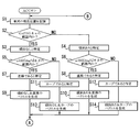
- FIG. 2A is the first half of the flowchart.
- FIG. 2B is the latter half of the flowchart.
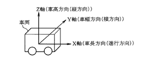
- FIG. 3A is a diagram illustrating an aspect of acquiring the tilt angle.
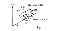
- FIG. 3B is a diagram illustrating an aspect of acquiring the tilt angle.
- FIG. 3C is a diagram illustrating an aspect of acquiring the tilt angle.
- FIG. 3D is a diagram illustrating an aspect of acquiring the tilt angle.
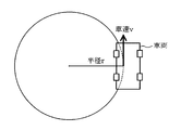
- FIG. 4 is a diagram illustrating an aspect of acquiring the curve radius.
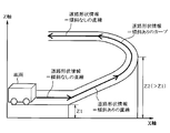
- FIG. 5 is a diagram showing road shape information.
- a road shape information collection and delivery system 1 is configured such that a road shape information generation device 2 mounted on a vehicle and a server 3 installed in a center can communicate data via a communication network. ing.
- a server 3 installed in a center
- an unspecified number of road shape information generation devices 2 can perform data communication with the server 3.
- the road shape information generating device 2 includes a control unit 4 (corresponding to control means), a CAN (Controller Area Network) communication unit 5, a GNSS (Global Navigation Satellite System) receiver 6, a power supply control unit 7, and a wide area communication unit. 8 (corresponding to a first communication unit (means) and a second communication unit (means)), a USB (Universal Serial Bus) interface (IF) unit 9, and a storage unit 10.
- the control unit 4 includes a microcomputer having a CPU (Central Processing Unit), a ROM (Read Only Memory), a RAM (Random Access Memory), and an I / O (Input / Output). The control unit 4 controls the operation of the entire apparatus by executing a stored computer program.
- the CAN communication unit 5 has a data communication function with the CAN 11, and includes an acceleration sensor 12, an angular velocity sensor 13, a vehicle speed sensor 14, a driving operation support device 15, a travel control support device 16 and the like mounted on the vehicle. Data communication via the CAN 11 is controlled.
- the angular velocity sensor 13 detects and outputs an angular velocity acting in the vehicle traveling direction in the horizontal direction of the vehicle.
- the vehicle speed sensor 14 counts the number of vehicle speed pulses, and detects and outputs the vehicle speed.
- the CAN communication unit 5 inputs each sensor value from the acceleration sensor 12, the angular velocity sensor 13, and the vehicle speed sensor 14 via the CAN 11, the CAN communication unit 5 outputs the input sensor value to the control unit 4.
- the CAN communication unit 5 outputs driving operation support information to the driving operation support device 15 via the CAN 11 and outputs driving control support information to the driving control support device 15 via the CAN 11.
- the driving operation support device 15 is a device that supports (assists) the driving operation of the driver.
- the driving operation supporting device 15 displays a display that displays guidance (such as guidance that alerts the pedestrian) or voice. A speaker or the like.
- the travel control support device 15 is a device that supports vehicle travel control, and is, for example, a brake ECU (Electronic Control Unit) that performs control to support deceleration, an accelerator ECU that performs control to support acceleration, or the like.
- the GNSS receiver 6 captures a satellite signal emitted from an artificial satellite, calculates various parameters, calculates coordinates (latitude and longitude and altitude) indicating the current position of the vehicle, and outputs the calculated coordinates to the control unit 4. To do.
- the power supply control unit 7 monitors the ACC (accessory) signal. When the power supply control unit 7 detects the switching of the ACC signal from off (0) to on (1), the power control unit 7 detects the operating power supplied from the vehicle battery (not shown). Supply to each functional block is started, and the entire apparatus is set in an activated state (wake-up state).
- the power supply control unit 7 when the power supply control unit 7 detects that the ACC signal is switched from on to off, the power supply control unit 7 stops the supply of the operating power to each functional block and puts the entire apparatus into a stopped state (sleep state).
- the power supply control unit 7 may be configured to switch the entire apparatus between a start state and a stop state by monitoring an IG (ignition) signal and a CAN wakeup signal.
- the wide area communication unit 8 performs data communication with the server 3 via a communication network.
- the USBIF unit 9 has a data communication function conforming to the USB communication standard.
- the storage unit 10 includes a road shape information database 10a (corresponding to a road shape information storage unit (means)) capable of storing (storing) road shape information, and a support information database 10b (support information storage unit) capable of storing support information. (Corresponding to (means)).
- the control unit 4 includes a sensor value acquisition unit 4a (corresponding to a sensor value acquisition unit), a position acquisition unit 4b (corresponding to a position acquisition unit), a road shape information generation unit 4c (corresponding to a road shape information generation unit), Support information generation section 4d (corresponding to support information generation means), storage control section 4e (corresponding to storage control means), communication control section 4f (first communication control section (means), second communication control section ( Means)).
- sensor value acquisition unit 4a, position acquisition unit 4b, road shape information generation unit 4c, support information generation unit 4d, storage control unit 4e and communication control unit 4f are computer programs (road shape information generation program executed by the control unit 4). And is implemented by software.
- the sensor value acquisition unit 4a acquires the sensor values of the sensors 12 to 14 from the CAN communication unit 5.
- the position acquisition unit 4b acquires coordinates indicating the current position of the vehicle from the GNSS receiver 6.
- the road shape information generation unit 4c generates information on the shape of the road as road shape information based on the sensor value acquired by the sensor value acquisition unit 4a and the coordinates acquired by the position acquisition unit 4b.
- the storage control unit 4e stores the generated road shape information in the road shape information database 10a.
- the support information generation unit 4d processes the road shape information stored in the road shape information database 10a to generate support information.
- the storage control unit 4e stores the generated support information in the support information database 10b.
- the communication control unit 4f causes the wide area communication unit 8 to transmit the road shape information stored in the road shape information database 10a and the support information stored in the support information database 10b to the server 3 via the communication network.
- the communication control unit 4f may transmit the road shape information and support information at any timing. For example, immediately after the ACC signal is switched from on to off, that is, the road shape information generation device 2 is activated. It may be transmitted immediately before shifting to the stop state. Further, the communication control unit 4f may cause the generated road shape information to be transmitted immediately after the road shape information generation unit 4c generates the road shape information, or the support information generation unit 4d generates the support information. Immediately after that, the generated support information may be transmitted. That is, the communication control unit 4f may cause the generated road shape information and support information to be transmitted in real time.
- the server 3 has a road shape information database 3a and a support information database 3b.
- the road shape information database 3a of the server 3 has a larger capacity than the road shape information database 10a of the road shape information generation device 2 described above, and can store more road shape information data.
- the support information database 3b of the server 3 has a larger capacity than the support information database 10b of the road shape information generation device 2 described above, and can store more support information data.
- the server 3 When the server 3 receives the road shape from the road shape information generation device 2, the server 3 stores the received road shape information in the road shape information database 3 a and receives the support information from the road shape information generation device 2, the received support Information is stored in the support information database 3b.
- the server 3 processes the road shape information received from the road shape information generation device 2 to generate support information, and stores the generated support information in the support information database 3b.
- the server 3 is configured to be capable of data communication with the vehicle device 17 mounted on the vehicle via a communication network, and is stored in the road shape information and support information database 3b stored in the road shape information database 3a. The supported information is distributed to the vehicle device 17 via the communication network.
- the server 3 can transmit and receive road shape information and support information to and from an unspecified number of road shape information generation devices 2 having a function of generating road shape information and support information.
- the road shape information and the support information can be distributed to an unspecified number of vehicle devices 17 that do not have the function of generating
- the control unit 4 performs the processing shown in FIGS. 2A and 2B when the ACC signal is on, that is, when the road shape information generation device 2 is in the activated state. Note that the control unit 4 periodically acquires the sensor values of the sensors 12 to 14 from the CAN communication unit 5 in a predetermined cycle (for example, several milliseconds) when the ACC is on. Is periodically acquired from the GNSS receiver 6 at a predetermined cycle (for example, a cycle of several milliseconds).
- the control unit 4 stores coordinates indicating the current position of the vehicle acquired from the GNSS receiver 6 (S1). Next, the control unit 4 determines an inclination angle in the vehicle traveling direction of the traveling road based on the sensor value acquired from the acceleration sensor 12 (S2, first procedure). More specifically, as shown in FIG. 3A, the vehicle length direction (traveling direction) is defined as the X axis, the vehicle width direction (lateral direction) is defined as the Y axis, and the vehicle height direction (vertical direction) is defined as the Z axis. In this case, as shown in FIG.
- the acceleration value acting in the direction opposite to the vehicle traveling direction is equal to the sin component of Gz and is “sin ⁇ ⁇ 1 G”, as shown in FIG. 3D.
- the acceleration value acting in the direction opposite to the traveling direction of the vehicle is obtained by subtracting the sin component of Gz from “A”. A-sin ⁇ ⁇ 1G ”.
- the control unit 4 determines that the measurement error of the acceleration sensor 12 is “ ⁇ ” and the acceleration value acting in the vertical direction from the vehicle toward the road surface is within the range of “1G ⁇ ⁇ ” (S2: YES)
- the inclination angle is specified as “0” (no inclination) (S3).
- the control unit 4 determines that the acceleration value acting in the vertical direction from the vehicle toward the road surface is not within the range of “1G ⁇ ⁇ ” (out of the range) (S2: NO)
- the inclination angle is “ ⁇ ”(with inclination) is identified (S4).
- control unit 4 utilizes the fact that the acceleration value acting in the vertical direction from the vehicle toward the road surface changes according to the presence or absence of the inclination, and whether or not the value is within the range of “1G ⁇ ⁇ ”. By determining whether or not there is an inclination in the vehicle traveling direction of the traveling road.
- the control unit 4 determines the presence or absence of a curve in the vehicle traveling direction of the traveling road based on the sensor value acquired from the angular velocity sensor 13 (S5, S6, first procedure).
- the control unit 4 determines that the measurement error of the angular velocity sensor 13 is “ ⁇ ” and the sensor value acquired from the angular velocity sensor 13 is within the range of “0 deg / s ⁇ ⁇ ” (S5: YES, S6: YES)
- it is specified that the shape of the road in the vehicle traveling direction is a straight line (S7, S8).
- the control part 4 specifies that there is no inclination and it is a straight line, the vector which shows that will be produced
- the control unit 4 specifies that the vehicle is inclined and straight, the control unit 4 generates a vector indicating the fact as road shape information (S10, second procedure).
- the control unit 4 determines that the sensor value acquired from the angular velocity sensor 13 is not within the range of “0 deg / s ⁇ ⁇ ” (out of range) (S5: NO, S6: NO), the vehicle travels on the road. It is specified that the shape of the direction is a curve (S11, S12). And when the control part 4 specifies that it is a curve without an inclination, the vector which shows that is produced
- generated as road shape information (S13, 2nd procedure). At this time, as shown in FIG. 4, the control unit 4 sets the curve radius to “r (curvature is 1 / r)” and the vehicle speed to “v”, and the relationship “v r ⁇ ⁇ ” is established. Therefore, the curve radius is calculated using the sensor value acquired from the vehicle speed sensor 14, and the turning angle “ ⁇ ” is calculated by integrating the angular velocity with time.
- control unit 4 when the control unit 4 specifies that the vehicle is inclined and is a curve, the control unit 4 generates a vector indicating the fact as road shape information (S14, second procedure). Also at this time, the control unit 4 calculates the curve radius using the sensor value acquired from the vehicle speed sensor 14 and calculates the turning angle “ ⁇ ” by integrating the angular velocity with time. As described above, the control unit 4 utilizes the fact that the value of the angular velocity acting in the vehicle traveling direction in the horizontal direction of the vehicle changes according to the presence or absence of the curve, and the value is within the range of “0 deg / s ⁇ ⁇ ”. Whether or not there is a curve in the vehicle traveling direction of the traveling road is determined.
- the control unit 4 refers to the road shape information database 10a, and the road shape information (past road shape information, past vector) in the same section as the road shape information generated by the current road shape determination is the road shape information database. It is determined whether it is stored in 10a (S15). If it is determined that the road shape information of the same section as the road shape information generated by the current road shape determination is stored (S15: YES), the control unit 4 is combined with the stored past road shape information. Average (S16), and store (update) the averaged road shape information in the road shape information database 10a (S17, third procedure).
- control part 4 compares the coordinate which shows the present position of the vehicle acquired by this road shape determination, and the coordinate which shows the present position of the vehicle acquired by past road shape determination, and the shift
- the control unit 4 determines that the deviation of the current position of the vehicle is equal to or greater than a preset value (S19: YES)
- the coordinate indicating the current position of the vehicle acquired by the current road shape determination is the latest.
- the coordinates are stored in the road shape information database 10a in association with the road shape information (S20).
- the control part 4 improves the precision (reliability) of road shape information by averaging road shape information.
- control unit 4 determines that the road shape information of the same section as the road shape information generated by the current road shape determination is not stored (S15: NO)
- the control unit 4 determines the current road shape information as the road shape information database 10a. (S21, third procedure), and the coordinates indicating the current position of the vehicle acquired by the current road shape determination are associated with the road shape information as the latest coordinates and stored in the road shape information database 10a ( S22).
- control unit 4 determines that the ACC signal is switched from OFF to ON (S23) and determines that the ACC signal continues to be ON (S23: NO)
- the control unit 4 returns to the above-described step S1 and performs similar processing. Repeat this step.
- the control unit 4 sequentially generates road shape information while the vehicle is traveling as shown in FIG. 5 by performing the processing described above. In the example of FIG. 5, the control unit 4 sequentially generates “straight line without inclination”, “straight line with inclination”, “curve with inclination”, and “straight line without inclination” as road shape information.
- the control unit 4 processes the road shape information generated during the traveling of the vehicle in this way to generate support information, and stores the generated support information in the support information database 10b. .
- the control unit 4 generates, as support information, driving operation support information that supports the driving operation of the driver and driving control support information that supports driving control of the vehicle.
- the control unit 4 obtains the necessary driving operation support information and the travel control support information according to the current position of the vehicle.
- the control unit 4 displays guidance for prompting a brake operation on the display and voice from the speaker. Or output a command to the brake ECU to assist the deceleration. Further, for example, in the case of a hybrid vehicle using an electric motor as a drive source, the normal operation is shifted to the eco-friendly operation by shifting from the normal mode to the energy regression mode.
- the server 3 receives the road shape information from the road shape information generation device 2, processes the received road shape information to generate support information, and uses the generated support information as the road shape information generation device 2 or the vehicle. It may be distributed (feedback) to the device 17. That is, in the road shape information collection and delivery system 1, the road shape information generation device 2 may generate support information, or the server 3 processes road shape information collected from an unspecified number of road shape information generation devices 2. Support information may be generated. Then, the server 3 may distribute the support information to an unspecified number of road shape information generation devices 2 and vehicle devices 17.
- the sensor value acquired from each of the sensors 12 to 14 is input from the CAN communication unit 5 to generate the information regarding the inclination angle and the curve radius of the vehicle traveling direction on the road. Coordinates may be input from the GNSS receiver 6 to generate information regarding the width of the road. That is, the control unit 4 specifies that the width of the road is relatively wide when the variation in coordinates indicating the current position of the vehicle in the predetermined range is relatively large, and the width of the road is relatively large when the variation is relatively small. You may specify that it is too narrow.
- the road shape information generation device 2 uses the road shape based on the sensor values obtained from the sensors 12 to 14 without using means for photographing a vehicle traveling on the road or means for image processing and analyzing image data. Information was generated and stored. As a result, road shape information can be generated appropriately without requiring a high-spec CPU or a large-capacity memory without incurring a complicated configuration or high cost, and the generated road shape information can be used effectively. can do.
- information on the inclination angle of the road in the vehicle traveling direction is generated based on the sensor value indicating the acceleration in the gravity direction. Thereby, the information regarding the inclination angle of the vehicle traveling direction on the road can be generated.
- information on the curve radius of the road in the vehicle traveling direction on the road is generated based on the sensor value indicating the angular velocity acting in the vehicle traveling direction in the horizontal direction of the vehicle and the sensor value indicating the vehicle speed. Thereby, the information regarding the curve radius of the vehicle traveling direction on the road can be generated.
- the road shape information is processed to generate driving operation support information that supports the driving operation of the driver and driving control support information that supports the driving control of the vehicle. Accordingly, it is possible to appropriately assist the driver's driving operation and vehicle traveling control according to the inclination angle and the curve radius of the road in the vehicle traveling direction.
- the server 3 receives and collects road shape information and support information from an unspecified number of road shape information generation devices 2, or collects road shape information and support information from an unspecified number of road shape information generation devices 2 and vehicles. Or distributed to the device 17.
- an unspecified number of road shape information generation devices 2 and vehicle devices 17 can share road shape information and support information.
- road shape information and support information provided from another road shape information generation device 2 By using, driving operation and traveling control can be appropriately supported even on a road that travels for the first time.
- the configuration in which the road shape information generating device 2 is provided as a dedicated device for generating the road shape information is illustrated, but the function described in the above embodiment is incorporated in a device having another function. May be. That is, the function described in the above embodiment may be incorporated in, for example, a navigation device.
- each sensor 12 to 14 is incorporated in the road shape information generation device 2. There may be.
- the configuration in which the road shape information and the support information are transmitted to the server 3 as an aspect of outputting the road shape information and the support information to the outside is exemplified.
- the road shape information and the support information are transferred to a recording medium such as a USB memory.
- road shape information and support information may be used.
Landscapes
- Physics & Mathematics (AREA)
- General Physics & Mathematics (AREA)
- Engineering & Computer Science (AREA)
- Radar, Positioning & Navigation (AREA)
- Remote Sensing (AREA)
- Chemical & Material Sciences (AREA)
- Analytical Chemistry (AREA)
- Life Sciences & Earth Sciences (AREA)
- Atmospheric Sciences (AREA)
- Automation & Control Theory (AREA)
- Theoretical Computer Science (AREA)
- Traffic Control Systems (AREA)
Abstract
道路形状情報生成装置(2)を提供する。道路形状情報生成装置は、車両が走行することで当該車両に作用するセンサ値を取得するセンサ値取得部(4a)と、前記センサ値取得部により取得されたセンサ値に基づいて道路の形状に関する情報を道路形状情報として生成する道路形状情報生成部(4c)と、前記道路形状情報生成部により生成された道路形状情報を道路形状情報記憶部(10a)に記憶させる記憶制御部(4e)と、を備える。
Description
本出願は、2015年1月15日に出願された日本国特許出願2015-5906号に基づくものであり、その開示をここに参照により援用する。
本開示は、道路の形状に関する情報を生成する道路形状情報生成装置、道路形状情報集配システム及び道路形状情報生成プログラムに関する。
従来より、移動体の移動軌跡を生成する構成として、飛翔体を撮影して画像データを取得し、その取得した画像データを画像処理して解析する構成がある(例えば特許文献1参照)。
移動体が車両(自動車)の場合でも特許文献1を適用することで、例えば傾斜角度やカーブ半径等の道路の形状に関する情報(道路形状情報)を生成可能となる。しかしながら、特許文献1を適用して道路形状情報を生成する構成では、道路を走行する車両を撮影するための手段が必要となり、撮影した画像データを画像処理して解析する手段も必要となる。その結果、高スペックなCPUや大容量のメモリを必要とし、構成の複雑化やコスト高を招く。
本開示の目的の一つは、上記した事情に鑑みて、構成の複雑化やコスト高を招くことなく道路の形状に関する情報を適切に生成することができ、その生成した情報を有効に活用することができる道路形状情報生成装置、道路形状情報集配システム及び道路形状情報生成プログラムを提供することにある。
本開示の一例に係る道路形状情報生成装置は、車両が走行することで当該車両に作用するセンサ値を取得するセンサ値取得部と、前記センサ値取得部により取得されたセンサ値に基づいて道路の形状に関する情報を道路形状情報として生成する道路形状情報生成部と、前記道路形状情報生成部により生成された道路形状情報を道路形状情報記憶部に記憶させる記憶制御部と、を備えた道路形状情報生成装置である。
この道路形状情報生成装置は、前記道路形状情報記憶部に記憶されている道路形状情報を第1の通信部からサーバに送信させる第1の通信制御部をさらに備えてもよい。この道路形状情報生成装置と、このサーバとが、道路形状情報集配システムを構成してもよい。
本開示の一例に係る道路形状情報生成プログラムは、道路形状情報生成装置の制御部に、車両が走行することで当該車両に作用するセンサ値を取得する第1の手順と、前記第1の手順により取得したセンサ値に基づいて道路形状に関する情報を道路形状情報として生成する第2の手順と、前記第2の手順により生成した道路形状情報を道路形状情報記憶部に記憶させる第3の手順と、を実行させる道路形状情報生成プログラムである。道路形状情報生成プログラムは、非一時的な記憶媒体に記憶されていてもよい。
上述の道路形状情報生成装置、道路形状情報集配システム及び道路形状情報生成プログラムによれば、道路を走行する車両を撮影するための手段や画像データを画像処理して解析する手段を用いずに、車両が走行することで当該車両に作用するセンサ値に基づいて道路形状情報を生成し、その生成した道路形状情報を記憶する。これにより、高スペックなCPUや大容量のメモリを必要とせずに構成の複雑化やコスト高を招くことなく道路形状情報を適切に生成することができる。そして、その生成した道路形状情報を記憶することで、その生成した道路形状情報を加工したり外部に送信したりすることができ、道路形状情報を有効に活用することができる。
本開示についての上記および他の目的、特徴や利点は、添付図面を参照した下記の詳細な説明から、より明確になる。添付図面において、
図1は、一実施形態の道路形状情報集配システムの全体構成を示す図である。
図2Aは、フローチャートの前半部である。
図2Bは、フローチャートの後半部である。
図3Aは、傾斜角度を取得する態様を示す図である。
図3Bは、傾斜角度を取得する態様を示す図である。
図3Cは、傾斜角度を取得する態様を示す図である。
図3Dは、傾斜角度を取得する態様を示す図である。
図4は、カーブ半径を取得する態様を示す図である。
図5は、道路形状情報を示す図である。
以下、一実施形態について図面を参照して説明する。図1に示すように、道路形状情報集配システム1は、車両に搭載されている道路形状情報生成装置2と、センターに設置されているサーバ3とが通信ネットワークを介してデータ通信可能に構成されている。本実施形態では、不特定多数の道路形状情報生成装置2がサーバ3とデータ通信可能である。
道路形状情報生成装置2は、制御部4(制御手段に相当)と、CAN(Controller Area Network)通信部5と、GNSS(Global Navigation Satellite System)レシーバ6と、電源制御部7と、広域通信部8(第1の通信部(手段)、第2の通信部(手段)に相当)と、USB(Universal Serial Bus)インタフェース(IF)部9と、記憶部10とを有する。制御部4は、CPU(Central Processing Unit)、ROM(Read Only Memory)、RAM(Random Access Memory)及びI/O(Input/Output)を有するマイクロコンピュータにより構成されている。制御部4は、記憶しているコンピュータプログラムを実行することで、装置全体の動作を制御する。
CAN通信部5は、CAN11との間でのデータ通信機能を有し、車両に搭載されている加速度センサ12、角速度センサ13、車速センサ14、運転操作支援装置15、走行制御支援装置16等との間のCAN11を介したデータ通信を制御する。加速度センサ12は、重力方向の加速度(重力加速度G=9.80665m/s2)を検出して出力する。角速度センサ13は、車両の水平方向において車両進行方向に作用する角速度を検出して出力する。車速センサ14は、車速パルスのパルス数をカウントし、車速を検出して出力する。CAN通信部5は、加速度センサ12、角速度センサ13、車速センサ14から各センサ値をCAN11を介して入力すると、その入力した各センサ値を制御部4に出力する。
又、CAN通信部5は、運転操作支援情報をCAN11を介して運転操作支援装置15に出力したり走行制御支援情報をCAN11を介して走行制御支援装置15に出力したりする。運転操作支援装置15は、運転者の運転操作を支援する(アシストする)装置であり、例えば運転操作を支援するガイダンス(歩行者への注意を喚起するガイダンス等)を表示するディスプレイや音声出力するスピーカ等である。走行制御支援装置15は、車両の走行制御を支援する装置であり、例えば減速を支援する制御を行うブレーキECU(Electronic Control Unit)や加速を支援する制御を行うアクセルECU等である。
GNSSレシーバ6は、人工衛星から放射された衛星信号を捕捉して各種パラメータを演算し、車両の現在位置を示す座標(緯度経度及び高度)を算出し、その算出した座標を制御部4に出力する。電源制御部7は、ACC(アクセサリ)信号を監視しており、ACC信号のオフ(0)からオン(1)への切り替わりを検知すると、車両バッテリ(図示せず)から供給された動作電力の各機能ブロックへの供給を開始し、装置全体を起動状態(ウェイクアップ状態)とする。又、電源制御部7は、ACC信号のオンからオフへの切り替わりを検知すると、動作電力の各機能ブロックへの供給を停止し、装置全体を停止状態(スリープ状態)とする。尚、電源制御部7は、IG(イグニッション)信号やCANのウェイクアップ信号を監視することで、装置全体を起動状態と停止状態とに切り替える構成でも良い。
広域通信部8は、サーバ3との間で通信ネットワークを介してデータ通信を行う。USBIF部9は、USBの通信規格に準じたデータ通信機能を有する。記憶部10は、道路形状情報を記憶可能(格納可能)な道路形状情報データベース10a(道路形状情報記憶部(手段)に相当)と、支援情報を記憶可能な支援情報データベース10b(支援情報記憶部(手段)に相当)とを有する。
制御部4は、センサ値取得部4a(センサ値取得手段に相当)と、位置取得部4b(位置取得手段に相当)と、道路形状情報生成部4c(道路形状情報生成手段に相当)と、支援情報生成部4d(支援情報生成手段に相当)と、記憶制御部4e(記憶制御手段に相当)と、通信制御部4f(第1の通信制御部(手段)、第2の通信制御部(手段)に相当)とを有する。これらセンサ値取得部4a、位置取得部4b、道路形状情報生成部4c、支援情報生成部4d、記憶制御部4e及び通信制御部4fは、制御部4が実行するコンピュータプログラム(道路形状情報生成プログラムを含む)により構成されており、ソフトウェアにより実現されている。
センサ値取得部4aは、各センサ12~14のセンサ値をCAN通信部5から取得する。位置取得部4bは、車両の現在位置を示す座標をGNSSレシーバ6から取得する。道路形状情報生成部4cは、センサ値取得部4aにより取得されたセンサ値や位置取得部4bにより取得された座標に基づいて道路の形状に関する情報を道路形状情報として生成する。道路形状情報生成部4cが道路形状情報を生成すると、記憶制御部4eは、その生成された道路形状情報を道路形状情報データベース10aに記憶させる。支援情報生成部4dは、道路形状情報データベース10aに記憶されている道路形状情報を加工して支援情報を生成する。支援情報生成部4dが支援情報を生成すると、記憶制御部4eは、その生成された支援情報を支援情報データベース10bに記憶させる。
通信制御部4fは、道路形状情報データベース10aに記憶されている道路形状情報や支援情報データベース10bに記憶されている支援情報を広域通信部8から通信ネットワークを介してサーバ3に送信させる。尚、通信制御部4fは、道路形状情報や支援情報をどのようなタイミングで送信させても良く、例えばACC信号がオンからオフに切り替わった直後、即ち、道路形状情報生成装置2が起動状態から停止状態に移行する直前で送信させても良い。又、通信制御部4fは、道路形状情報生成部4cが道路形状情報を生成した直後に、その生成された道路形状情報を送信させても良いし、支援情報生成部4dが支援情報を生成した直後に、その生成された支援情報を送信させても良い。即ち、通信制御部4fは、生成された道路形状情報や支援情報をリアルタイムに送信させても良い。
サーバ3は、道路形状情報データベース3aと、支援情報データベース3bとを有する。サーバ3の道路形状情報データベース3aは、上記した道路形状情報生成装置2の道路形状情報データベース10aよりも大容量であり、より多くの道路形状情報データを記憶可能となっている。同様に、サーバ3の支援情報データベース3bは、上記した道路形状情報生成装置2の支援情報データベース10bよりも大容量であり、より多くの支援情報データを記憶可能となっている。
サーバ3は、道路形状情報生成装置2から道路形状を受信すると、その受信した道路形状情報を道路形状情報データベース3aに記憶し、道路形状情報生成装置2から支援情報を受信すると、その受信した支援情報を支援情報データベース3bに記憶する。又、サーバ3は、道路形状情報生成装置2から受信した道路形状情報を加工して支援情報を生成し、その生成した支援情報を支援情報データベース3bに記憶する。更に、サーバ3は、車両に搭載されている車両装置17と通信ネットワークを介してデータ通信可能に構成されており、道路形状情報データベース3aに記憶されている道路形状情報や支援情報データベース3bに記憶されている支援情報を通信ネットワークを介して車両装置17に配信する。即ち、サーバ3は、道路形状情報や支援情報を生成する機能を有する不特定多数の道路形状情報生成装置2との間では道路形状情報や支援情報を送受信可能であり、道路形状情報や支援情報を生成する機能を有しない不特定多数の車両装置17に道路形状情報や支援情報を配信可能である。
次に、上記した構成の作用について、図2Aから図5を参照して説明する。制御部4は、ACC信号がオンの状態、即ち、道路形状情報生成装置2が起動状態では図2Aおよび図2Bに示す処理を行う。尚、制御部4は、ACCがオンの状態では、各センサ12~14のセンサ値をCAN通信部5から所定周期(例えば数ミリ秒周期)で定期的に取得しており、車両の現在位置を示す座標をGNSSレシーバ6から所定周期(例えば数ミリ秒周期)で定期的に取得している。
制御部4は、GNSSレシーバ6から取得した車両の現在位置を示す座標を記憶する(S1)。次いで、制御部4は、加速度センサ12から取得したセンサ値に基づいて走行中の道路の車両進行方向の傾斜角度を判定する(S2、第1の手順)。具体的に説明すると、図3Aに示すように、車長方向(進行方向)をX軸、車幅方向(横方向)をY軸、車高方向(縦方向)をZ軸と定義する。この場合、図3Bに示すように、車両が走行中の道路の車両進行方向の傾斜角度が0度(傾斜なし)であれば、車両から路面に向かって垂直方向に作用する加速度の値は、Gzと等しく「1G」となる。一方、図3Cおよび図3Dに示すように、車両が走行中の道路の車両進行方向の傾斜角度が0度以外(傾斜あり)であれば、傾斜角度を「θ」とすると、車両から路面に向かって垂直方向に作用する加速度の値は、Gzのcos成分と等しく「cosθ×1G」となる。尚、図3Cに示すように、車両が等速であれば、車両進行方向とは反対方向に作用する加速度の値は、Gzのsin成分と等しく「sinθ×1G」となり、図3Dに示すように、車両が進行方向に加速していれば、進行方向への加速度を「A」とすると、車両進行方向とは反対方向に作用する加速度の値は、AからGzのsin成分を差し引いた「A-sinθ×1G」となる。
制御部4は、加速度センサ12の測定誤差を「α」とし、車両から路面に向かって垂直方向に作用する加速度の値が「1G±α」の範囲内であると判定すると(S2:YES)、傾斜角度が「0」である(傾斜なし)と特定する(S3)。一方、制御部4は、車両から路面に向かって垂直方向に作用する加速度の値が「1G±α」の範囲内でない(範囲外である)と判定すると(S2:NO)、傾斜角度が「θ」である(傾斜あり)と特定する(S4)。このように制御部4は、車両から路面に向かって垂直方向に作用する加速度の値が傾斜の有無にしたがって変化することを利用し、その値が「1G±α」の範囲内であるか否かを判定することで、走行中の道路の車両進行方向の傾斜の有無を特定する。
次いで、制御部4は、角速度センサ13から取得したセンサ値に基づいて走行中の道路の車両進行方向のカーブの有無を判定する(S5、S6、第1の手順)。制御部4は、角速度センサ13の測定誤差を「β」とし、角速度センサ13から取得したセンサ値が「0deg/s±β」の範囲内であると判定すると(S5:YES、S6:YES)、道路の車両進行方向の形状が直線であると特定する(S7、S8)。そして、制御部4は、傾斜なしで且つ直線であると特定したときには、その旨を示すベクトルを道路形状情報として生成する(S9、第2の手順)。又、制御部4は、傾斜ありで且つ直線であると特定したときには、その旨を示すベクトルを道路形状情報として生成する(S10、第2の手順)。
一方、制御部4は、角速度センサ13から取得したセンサ値が「0deg/s±β」の範囲内でない(範囲外である)と判定すると(S5:NO、S6:NO)、道路の車両進行方向の形状がカーブであると特定する(S11、S12)。そして、制御部4は、傾斜なしで且つカーブであると特定したときには、その旨を示すベクトルを道路形状情報として生成する(S13、第2の手順)。このとき、制御部4は、図4に示すように、カーブ半径を「r(曲率は1/r)」とし、車速を「v」とすると、「v=r×ω」の関係が成立するので、車速センサ14から取得したセンサ値を用いてカーブ半径を算出し、角速度を時間で積分して旋回角度「φ」を算出する。
又、制御部4は、傾斜ありで且つカーブであると特定したときには、その旨を示すベクトルを道路形状情報として生成する(S14、第2の手順)。このときも、制御部4は、車速センサ14から取得したセンサ値を用いてカーブ半径を算出し、角速度を時間で積分して旋回角度「φ」を算出する。このように制御部4は、車両の水平方向において車両進行方向に作用する角速度の値がカーブの有無にしたがって変化することを利用し、その値が「0deg/s±β」の範囲内であるか否かを判定することで、走行中の道路の車両進行方向のカーブの有無を特定する。
次いで、制御部4は、道路形状情報データベース10aを参照し、今回の道路形状判定により生成した道路形状情報と同一区間の道路形状情報(過去の道路形状情報、過去のベクトル)が道路形状情報データベース10aに記憶されているか否かを判定する(S15)。制御部4は、今回の道路形状判定により生成した道路形状情報と同一区間の道路形状情報が記憶されていると判定すると(S15:YES)、その記憶されている過去の道路形状情報と併せて平均化し(S16)、その平均化した道路形状情報を道路形状情報データベース10aに記憶させる(更新する)(S17、第3の手順)。そして、制御部4は、今回の道路形状判定により取得した車両の現在位置を示す座標と、過去の道路形状判定により取得した車両の現在位置を示す座標とを比較し、車両の現在位置のずれ(座標の差)を判定する(S18)。制御部4は、車両の現在位置のずれが予め設定しておいた設定値以上であると判定すると(S19:YES)、今回の道路形状判定により取得した車両の現在位置を示す座標を最新の座標として道路形状情報と対応付けて道路形状情報データベース10aに記憶させる(S20)。このように制御部4は、道路形状情報を平均化することで、道路形状情報の精度(信頼性)を高める。
一方、制御部4は、今回の道路形状判定により生成した道路形状情報と同一区間の道路形状情報が記憶されていないと判定すると(S15:NO)、今回の道路形状情報を道路形状情報データベース10aに新たに記憶させ(S21、第3の手順)、今回の道路形状判定により取得した車両の現在位置を示す座標を最新の座標として道路形状情報と対応付けて道路形状情報データベース10aに記憶させる(S22)。
そして、制御部4は、ACC信号のオフからオンへの切り替えを判定し(S23)、ACC信号がオンし続けていると判定すると(S23:NO)、上記したステップS1に戻り、同様の処理を繰り返して行う。制御部4は、以上に説明した処理を行うことで、図5に示すように、車両の走行中では道路形状情報を順次生成する。図5の例示では、制御部4は、道路形状情報として、「傾斜なしの直線」、「傾斜ありの直線」、「傾斜ありのカーブ」、「傾斜なしの直線」を順次生成する。
道路形状情報生成装置2において、制御部4は、このようにして車両の走行中に生成した道路形状情報を加工して支援情報を生成し、その生成した支援情報を支援情報データベース10bに記憶させる。制御部4は、支援情報として、運転者の運転操作を支援する運転操作支援情報や車両の走行制御を支援する走行制御支援情報を生成する。制御部4は、運転操作支援情報や走行制御支援情報を生成して支援情報データベース10bに記憶させている場合には、車両の現在位置に応じて必要な運転操作支援情報や走行制御支援情報をCAN通信部5からCAN11を介して運転操作支援装置15や走行制御支援装置16に出力させることで、運転者の運転操作や車両の走行制御を支援する。具体的には、制御部4は、例えば傾斜が比較的大きく且つカーブ半径が比較的大きい下り坂に車両が進入しようとする際には、ブレーキ操作を促すガイダンスをディスプレイに表示させると共にスピーカから音声出力させたり、減速の支援をブレーキECUに指令したりする。又、例えば駆動源として電気モーターを使用するハイブリッド車等であれば、通常モードからエネルギー回帰モードに移行する等により、通常運転から地球環境に配慮したエコ運転に移行する。
尚、サーバ3において、道路形状情報生成装置2から道路形状情報を受信し、その受信した道路形状情報を加工して支援情報を生成し、その生成した支援情報を道路形状情報生成装置2や車両装置17に配信して(フィードバックして)も良い。即ち、道路形状情報集配システム1において、道路形状情報生成装置2が支援情報を生成しても良いし、サーバ3が不特定多数の道路形状情報生成装置2から収集した道路形状情報を加工して支援情報を生成しても良い。そして、サーバ3が支援情報を不特定多数の道路形状情報生成装置2や車両装置17に配信しても良い。
以上は、各センサ12~14から取得したセンサ値をCAN通信部5から入力して道路の車両進行方向の傾斜角度やカーブ半径に関する情報を生成する構成を説明したが、車両の現在位置を示す座標をGNSSレシーバ6から入力して道路の幅に関する情報を生成しても良い。即ち、制御部4は、所定範囲における車両の現在位置を示す座標のばらつきが相対的に大きいときには道路の幅が相対的に広いと特定し、ばらつきが相対的に小さいときには道路の幅が相対的に狭いと特定しても良い。
以上説明したように本実施形態によれば、次に示す効果を得ることができる。
道路形状情報生成装置2において、道路を走行する車両を撮影するための手段や画像データを画像処理して解析する手段を用いずに、各センサ12~14から取得したセンサ値に基づいて道路形状情報を生成して記憶するようにした。これにより、高スペックなCPUや大容量のメモリを必要とせずに構成の複雑化やコスト高を招くことなく道路形状情報を適切に生成することができ、その生成した道路形状情報を有効に活用することができる。
この場合、重力方向の加速度を示すセンサ値に基づいて道路の車両進行方向の傾斜角度に関する情報を生成するようにした。これにより、道路の車両進行方向の傾斜角度に関する情報を生成することができる。又、車両の水平方向において車両進行方向に作用する角速度を示すセンサ値及び車速を示すセンサ値に基づいて道路の車両進行方向のカーブ半径に関する情報を生成するようにした。これにより、道路の車両進行方向のカーブ半径に関する情報を生成することができる。又、ステアリングの旋回角度によりカーブ半径に関する情報を生成する方法ではステアリングの旋回角度が車種に依存するので、車種毎にテーブルが必要であるが、本実施形態のようにセンサ値に基づいてカーブ半径に関する情報を生成することで、車種に依存せずにカーブ半径に関する情報を生成することができる利点もある。
又、道路形状情報を加工して運転者の運転操作を支援する運転操作支援情報や車両の走行制御を支援する走行制御支援情報を生成するようにした。これにより、道路の車両進行方向の傾斜角度やカーブ半径に応じて運転者の運転操作や車両の走行制御を適切に支援することができる。
更に、サーバ3において、不特定多数の道路形状情報生成装置2から道路形状情報や支援情報を受信して収集したり、道路形状情報や支援情報を不特定多数の道路形状情報生成装置2や車両装置17に配信したりするようにした。これにより、不特定多数の道路形状情報生成装置2や車両装置17が道路形状情報や支援情報を共有することができ、例えば別の道路形状情報生成装置2から提供された道路形状情報や支援情報を活用することで、初めて走行する道路でも運転操作や走行制御を適切に支援することができる。
実施形態は、上記した実施形態に限定されることなく、本開示の技術的思想の範囲を逸脱しない範囲で任意に変形又は拡張することができる。
上記実施形態では、道路形状情報を生成する専用の装置として道路形状情報生成装置2が設けられている構成を例示したが、上記実施形態で説明した機能が別の機能を有する装置に組み込まれていても良い。即ち、上記実施形態で説明した機能が例えばナビゲーション装置に組み込まれていても良い。
上記実施形態では、道路形状情報生成装置2の外部の各センサ12~14からセンサ値を取得する構成を例示したが、各センサ12~14が道路形状情報生成装置2に組み込まれている構成であっても良い。
上記実施形態では、道路形状情報や支援情報を外部に出力する態様として、道路形状情報や支援情報をサーバ3に送信する構成を例示したが、例えばUSBメモリ等の記録媒体等に転送されることで、道路形状情報や支援情報を活用しても良い。
Claims (16)
- 車両が走行することで当該車両に作用するセンサ値を取得するセンサ値取得部(4a)と、
前記センサ値取得部により取得されたセンサ値に基づいて道路の形状に関する情報を道路形状情報として生成する道路形状情報生成部(4c)と、
前記道路形状情報生成部により生成された道路形状情報を道路形状情報記憶部(10a)に記憶させる記憶制御部(4e)と、を備えた道路形状情報生成装置(2)。 - 請求項1に記載した道路形状情報生成装置において、
前記センサ値取得部は、車両から路面に向かって垂直方向に作用する加速度を示すセンサ値を取得し、
前記道路形状情報生成部は、前記センサ値取得部により取得された加速度を示すセンサ値に基づいて道路の車両進行方向の傾斜角度に関する情報を道路形状情報として生成する道路形状情報生成装置。 - 請求項1又は2に記載した道路形状情報生成装置において、
前記センサ値取得部は、車両進行方向に作用する角速度を示すセンサ値及び車速を示すセンサ値を取得し、
前記道路形状情報生成部は、前記センサ値取得部により取得された角速度を示すセンサ値及び車速を示すセンサ値に基づいて道路の車両進行方向のカーブ半径に関する情報を道路形状情報として生成する道路形状情報生成装置。 - 請求項1から3の何れか一項に記載した道路形状情報生成装置において、
車両の現在位置を取得する位置取得部(4b)を備え、
前記道路形状情報生成部は、前記位置取得部により取得された車両の現在位置にも基づいて道路形状情報を生成する道路形状情報生成装置。 - 請求項4に記載した道路形状情報生成装置において
前記道路形状情報生成部は、道路の幅に関する情報を道路形状情報として生成する道路形状情報生成装置。 - 請求項4又は5に記載した道路形状情報生成装置において、
前記道路形状情報生成部は、前記センサ値取得部により取得されたセンサ値に基づいて生成した道路形状情報を、前記位置取得部により取得された車両の現在位置に基づいて補正する道路形状情報生成装置。 - 請求項1から6の何れか一項に記載した道路形状情報生成装置において、
前記道路形状情報記憶部に記憶されている道路形状情報を第1の通信部(8)からサーバ(3)に送信させる第1の通信制御部(4f)をさらに備えた道路形状情報生成装置。 - 請求項1から7の何れか一項に記載した道路形状情報生成装置において、
前記道路形状情報記憶部に記憶されている道路形状情報を加工して支援情報を生成する支援情報生成部(4d)をさらに備え、
前記記憶制御部は、前記支援情報生成部により生成された支援情報を支援情報記憶部(10b)に記憶させる道路形状情報生成装置。 - 請求項8に記載した道路形状情報生成装置において、
前記支援情報生成部は、運転者の運転操作を支援する運転操作支援情報又は車両の走行制御を支援する走行制御支援情報のうち少なくとも何れかを支援情報として生成する道路形状情報生成装置。 - 請求項8又は9に記載した道路形状情報生成装置において、
前記支援情報記憶部に記憶されている支援情報を第2の通信部(8)からサーバ(3)に送信させる第2の通信制御部(4f)をさらに備えた道路形状情報生成装置。 - 請求項7から10の何れか一項に記載した道路形状情報生成装置と、前記サーバとを備えた道路形状情報集配システム(1)。
- 請求項11に記載した道路形状情報集配システムにおいて、
前記サーバは、前記道路形状情報生成装置から受信した道路形状情報を記憶すると共に、その道路形状情報を加工して支援情報を生成し、その生成した支援情報を記憶する道路形状情報集配システム。 - 請求項12に記載した道路形状情報集配システムにおいて、
前記サーバは、運転者の運転操作を支援する運転操作支援情報又は車両の走行制御を支援する走行制御支援情報のうち少なくとも何れかを支援情報として生成する道路形状情報集配システム。 - 請求項12又は13に記載した道路形状情報集配システムにおいて、
前記サーバは、生成した支援情報を車両装置(17)に配信する道路形状情報集配システム。 - 道路形状情報生成装置(2)の制御部(4)に、
車両が走行することで当該車両に作用するセンサ値を取得する第1の手順と、
前記第1の手順により取得したセンサ値に基づいて道路形状に関する情報を道路形状情報として生成する第2の手順と、
前記第2の手順により生成した道路形状情報を道路形状情報記憶部(10a)に記憶させる第3の手順と、を実行させる道路形状情報生成プログラム。 - 請求項15に記載した道路形状情報生成プログラムを記憶した非一時的な記憶媒体。
Priority Applications (1)
| Application Number | Priority Date | Filing Date | Title |
|---|---|---|---|
| US15/538,969 US10311736B2 (en) | 2015-01-15 | 2016-01-07 | Road shape information generator, road shape information distribution system and road shape information generation program |
Applications Claiming Priority (2)
| Application Number | Priority Date | Filing Date | Title |
|---|---|---|---|
| JP2015-005906 | 2015-01-15 | ||
| JP2015005906A JP6443063B2 (ja) | 2015-01-15 | 2015-01-15 | 道路形状情報生成装置、道路形状情報集配システム及び道路形状情報生成プログラム |
Publications (1)
| Publication Number | Publication Date |
|---|---|
| WO2016114113A1 true WO2016114113A1 (ja) | 2016-07-21 |
Family
ID=56405665
Family Applications (1)
| Application Number | Title | Priority Date | Filing Date |
|---|---|---|---|
| PCT/JP2016/000061 Ceased WO2016114113A1 (ja) | 2015-01-15 | 2016-01-07 | 道路形状情報生成装置、道路形状情報集配システム及び道路形状情報生成プログラム |
Country Status (3)
| Country | Link |
|---|---|
| US (1) | US10311736B2 (ja) |
| JP (1) | JP6443063B2 (ja) |
| WO (1) | WO2016114113A1 (ja) |
Families Citing this family (3)
| Publication number | Priority date | Publication date | Assignee | Title |
|---|---|---|---|---|
| JP6443063B2 (ja) * | 2015-01-15 | 2018-12-26 | 株式会社デンソー | 道路形状情報生成装置、道路形状情報集配システム及び道路形状情報生成プログラム |
| KR20220046731A (ko) * | 2020-10-07 | 2022-04-15 | 현대자동차주식회사 | 자율주행장치 및 정밀지도 생성방법 |
| CN116631177A (zh) * | 2022-02-14 | 2023-08-22 | 浙江高信技术股份有限公司 | 基于行车状态信息的驾驶辅助指导系统及方法 |
Citations (4)
| Publication number | Priority date | Publication date | Assignee | Title |
|---|---|---|---|---|
| JP2002310680A (ja) * | 2001-04-09 | 2002-10-23 | Asia Air Survey Co Ltd | 交通安全情報提供方法及び交通安全情報提供のプログラム |
| JP2007225911A (ja) * | 2006-02-23 | 2007-09-06 | Hitachi Ltd | 道路地図情報収集方法、道路地図情報収集システムおよび道路地図情報処理装置 |
| JP2008186129A (ja) * | 2007-01-29 | 2008-08-14 | Denso Corp | 道路情報収集記憶装置 |
| JP2010091317A (ja) * | 2008-10-06 | 2010-04-22 | Ud Trucks Corp | レーダ装置 |
Family Cites Families (32)
| Publication number | Priority date | Publication date | Assignee | Title |
|---|---|---|---|---|
| JPH11184375A (ja) * | 1997-12-25 | 1999-07-09 | Toyota Motor Corp | デジタル地図データ処理装置及びデジタル地図データ処理方法 |
| JP3482166B2 (ja) * | 1999-12-08 | 2003-12-22 | 本田技研工業株式会社 | 車両用運転状況監視装置 |
| JP2001304903A (ja) * | 2000-04-27 | 2001-10-31 | Denso Corp | 分岐案内装置 |
| JP2002054934A (ja) | 2000-08-11 | 2002-02-20 | Denso Corp | 道路地図情報更新システム |
| JP4124213B2 (ja) * | 2005-05-27 | 2008-07-23 | トヨタ自動車株式会社 | 車両逸脱防止装置 |
| JP4169065B2 (ja) * | 2006-02-13 | 2008-10-22 | 株式会社デンソー | 車両制御装置 |
| JP4166253B2 (ja) * | 2006-07-10 | 2008-10-15 | トヨタ自動車株式会社 | 物体検出装置、物体検出方法、および物体検出用プログラム |
| JP4784452B2 (ja) * | 2006-09-12 | 2011-10-05 | 株式会社デンソー | 車載霧判定装置 |
| US9134133B2 (en) * | 2008-05-30 | 2015-09-15 | Here Global B.V. | Data mining to identify locations of potentially hazardous conditions for vehicle operation and use thereof |
| US8332143B2 (en) * | 2008-05-30 | 2012-12-11 | Navteq B.V. | Data mining in a digital map database to identify curves along downhill roads and enabling precautionary actions in a vehicle |
| US8775073B2 (en) * | 2008-05-30 | 2014-07-08 | Navteq B.V. | Data mining in a digital map database to identify insufficient merge lanes along roads and enabling precautionary actions in a vehicle |
| US8026835B2 (en) * | 2008-05-30 | 2011-09-27 | Navteq North America, Llc | Data mining in a digital map database to identify traffic signals, stop signs and yield signs at bottoms of hills and enabling precautionary actions in a vehicle |
| AU2008358268A1 (en) * | 2008-06-25 | 2009-12-30 | Tomtom International B.V. | Navigation apparatus and method of detection that a parking facility is sought |
| JP5441549B2 (ja) * | 2009-07-29 | 2014-03-12 | 日立オートモティブシステムズ株式会社 | 道路形状認識装置 |
| JP2011118795A (ja) | 2009-12-07 | 2011-06-16 | Tokyo Electric Power Co Inc:The | 移動軌跡図作成装置およびコンピュータプログラム |
| JP5601224B2 (ja) * | 2010-03-04 | 2014-10-08 | 株式会社デンソー | 道路形状学習装置 |
| JP5747482B2 (ja) * | 2010-03-26 | 2015-07-15 | 日産自動車株式会社 | 車両用環境認識装置 |
| JP5644373B2 (ja) | 2010-10-27 | 2014-12-24 | トヨタ自動車株式会社 | 情報処理装置 |
| US8467810B2 (en) * | 2010-11-29 | 2013-06-18 | Navteq B.V. | Method and system for reporting errors in a geographic database |
| JP2012118324A (ja) * | 2010-12-01 | 2012-06-21 | Ud Trucks Corp | 勾配情報データベース作成装置及び作成方法 |
| CN103238044B (zh) * | 2010-12-01 | 2016-08-24 | 沃尔沃拉斯特瓦格纳公司 | 扩充道路信息数据的方法 |
| US8700299B2 (en) * | 2011-02-24 | 2014-04-15 | Mitsubishi Electric Corporation | Navigation device, recommended speed arithmetic device, and recommended speed presentation device |
| JP2013008287A (ja) * | 2011-06-27 | 2013-01-10 | Toyota Central R&D Labs Inc | 道路勾配推定システム、道路勾配推定装置、及びプログラム |
| RU2566175C1 (ru) * | 2011-08-31 | 2015-10-20 | Ниссан Мотор Ко., Лтд. | Устройство помощи при вождении транспортного средства |
| JP5673597B2 (ja) * | 2011-11-18 | 2015-02-18 | 株式会社デンソー | 車両用挙動制御装置 |
| JP5892129B2 (ja) * | 2013-08-29 | 2016-03-23 | 株式会社デンソー | 道路形状認識方法、道路形状認識装置、プログラムおよび記録媒体 |
| JP6476557B2 (ja) * | 2014-03-07 | 2019-03-06 | 日産自動車株式会社 | 車両走行制御情報収集装置 |
| JP2016007894A (ja) * | 2014-06-23 | 2016-01-18 | トヨタ自動車株式会社 | 注意喚起装置及び走行制御装置 |
| US10533863B2 (en) * | 2014-10-10 | 2020-01-14 | Here Global B.V. | Apparatus and associated methods for use in lane-level mapping of road intersections |
| JP6443063B2 (ja) * | 2015-01-15 | 2018-12-26 | 株式会社デンソー | 道路形状情報生成装置、道路形状情報集配システム及び道路形状情報生成プログラム |
| JP6512084B2 (ja) * | 2015-12-04 | 2019-05-15 | 株式会社デンソー | 走行軌跡生成装置、走行軌跡生成方法 |
| JP2017111469A (ja) * | 2015-12-14 | 2017-06-22 | 富士通株式会社 | 道路標識視認判定システム、道路標識視認判定方法、及びプログラム |
-
2015
- 2015-01-15 JP JP2015005906A patent/JP6443063B2/ja not_active Expired - Fee Related
-
2016
- 2016-01-07 US US15/538,969 patent/US10311736B2/en active Active
- 2016-01-07 WO PCT/JP2016/000061 patent/WO2016114113A1/ja not_active Ceased
Patent Citations (4)
| Publication number | Priority date | Publication date | Assignee | Title |
|---|---|---|---|---|
| JP2002310680A (ja) * | 2001-04-09 | 2002-10-23 | Asia Air Survey Co Ltd | 交通安全情報提供方法及び交通安全情報提供のプログラム |
| JP2007225911A (ja) * | 2006-02-23 | 2007-09-06 | Hitachi Ltd | 道路地図情報収集方法、道路地図情報収集システムおよび道路地図情報処理装置 |
| JP2008186129A (ja) * | 2007-01-29 | 2008-08-14 | Denso Corp | 道路情報収集記憶装置 |
| JP2010091317A (ja) * | 2008-10-06 | 2010-04-22 | Ud Trucks Corp | レーダ装置 |
Also Published As
| Publication number | Publication date |
|---|---|
| JP2016133819A (ja) | 2016-07-25 |
| US10311736B2 (en) | 2019-06-04 |
| JP6443063B2 (ja) | 2018-12-26 |
| US20170352279A1 (en) | 2017-12-07 |
Similar Documents
| Publication | Publication Date | Title |
|---|---|---|
| US9796416B2 (en) | Automated driving apparatus and automated driving system | |
| CN105644438B (zh) | 车辆周边监视装置 | |
| JP6409699B2 (ja) | 自動運転システム | |
| US20200294325A1 (en) | High phone ble or cpu burden detection and notification | |
| EP3587205B1 (en) | Parking control device | |
| JP2016210255A (ja) | 車両走行制御装置 | |
| US11524694B2 (en) | Vehicle control apparatus, vehicle, vehicle control method, and non-transitory computer-readable storage medium | |
| JP6443063B2 (ja) | 道路形状情報生成装置、道路形状情報集配システム及び道路形状情報生成プログラム | |
| CN116615370B (zh) | 车辆控制装置、车辆控制系统、车辆控制方法及存储介质 | |
| CN112519758B (zh) | 确定停车可行性的设备和方法 | |
| CN111459121A (zh) | 车辆辅助驾驶测试系统和方法 | |
| CN118234651B (zh) | 驾驶控制方法及驾驶控制装置 | |
| JP6414005B2 (ja) | 車両用制御装置 | |
| JP7058629B2 (ja) | ソフトウェア更新装置、ソフトウェア更新方法、およびプログラム | |
| JP6674560B2 (ja) | 外界認識システム | |
| JP7458459B2 (ja) | 車両制御装置、車両制御方法、およびプログラム | |
| CN114872688B (zh) | 自动驾驶车辆、自动驾驶车辆的控制方法以及程序 | |
| CN113479205B (zh) | 移动体控制装置、移动体以及移动体控制方法 | |
| JP7007042B2 (ja) | 移動体制御装置 | |
| JP7125957B2 (ja) | 移動体制御装置、移動体及び移動体制御方法 | |
| JP7816203B2 (ja) | 情報制御装置 | |
| JP2019127189A (ja) | 駐車支援装置 | |
| JP2017197143A (ja) | 運転支援装置及びプログラム | |
| US11097734B2 (en) | Vehicle control device, vehicle, and vehicle control method | |
| JP2008260439A (ja) | 車両挙動制御装置及び車両挙動制御方法 |
Legal Events
| Date | Code | Title | Description |
|---|---|---|---|
| 121 | Ep: the epo has been informed by wipo that ep was designated in this application |
Ref document number: 16737184 Country of ref document: EP Kind code of ref document: A1 |
|
| WWE | Wipo information: entry into national phase |
Ref document number: 15538969 Country of ref document: US |
|
| NENP | Non-entry into the national phase |
Ref country code: DE |
|
| 122 | Ep: pct application non-entry in european phase |
Ref document number: 16737184 Country of ref document: EP Kind code of ref document: A1 |