WO2016114112A1 - 車両用電源制御装置 - Google Patents
車両用電源制御装置 Download PDFInfo
- Publication number
- WO2016114112A1 WO2016114112A1 PCT/JP2016/000060 JP2016000060W WO2016114112A1 WO 2016114112 A1 WO2016114112 A1 WO 2016114112A1 JP 2016000060 W JP2016000060 W JP 2016000060W WO 2016114112 A1 WO2016114112 A1 WO 2016114112A1
- Authority
- WO
- WIPO (PCT)
- Prior art keywords
- power supply
- temperature
- control device
- display
- unit
- Prior art date
- Legal status (The legal status is an assumption and is not a legal conclusion. Google has not performed a legal analysis and makes no representation as to the accuracy of the status listed.)
- Ceased
Links
Images


Classifications
-
- B—PERFORMING OPERATIONS; TRANSPORTING
- B60—VEHICLES IN GENERAL
- B60R—VEHICLES, VEHICLE FITTINGS, OR VEHICLE PARTS, NOT OTHERWISE PROVIDED FOR
- B60R16/00—Electric or fluid circuits specially adapted for vehicles and not otherwise provided for; Arrangement of elements of electric or fluid circuits specially adapted for vehicles and not otherwise provided for
- B60R16/02—Electric or fluid circuits specially adapted for vehicles and not otherwise provided for; Arrangement of elements of electric or fluid circuits specially adapted for vehicles and not otherwise provided for electric constitutive elements
Definitions
- the present disclosure relates to a vehicle power supply control device.
- a display is standardly installed in a passenger compartment of a luxury car, and there is a demand for a high-quality display function on the display.
- the passenger compartment reaches a temperature close to 85 ° C. and becomes extremely hot.
- displays are becoming more sophisticated and multifunctional, and an IC that consumes high power is mounted in order to realize these functions. For this reason, there is a tendency that the temperature rises due to heat generated from these high-power ICs.
- Patent Literature 1 discloses a technique for reducing the input power to the backlight when the temperature of the control unit of the display becomes a predetermined value or more. According to this technology, it can be expected to avoid further increase in temperature by reducing the power consumption of the backlight.
- the backlight is a functional part directly connected to the display function of the display. For this reason, if the input power of the backlight is reduced, the display quality of the display is deteriorated although the high temperature can be avoided.
- one of the objects of the present disclosure is to provide a vehicle power supply control device that can avoid a high temperature without causing deterioration in display quality of the display.
- a vehicle power supply control device includes a power supply to a display function unit that performs a display function for displaying various information on a display mounted in a vehicle interior, and a non-display function that performs a function other than the display function unit It is the vehicle power supply control apparatus which controls the power supply with respect to a part.
- the vehicle power supply control device cuts off the power supply to the non-display function unit. According to this configuration, heat generation from other non-display function units can be suppressed while maintaining power supply to the display function unit. Therefore, it is possible to avoid a high temperature without degrading the display quality of the display.
- the power supply control device includes a temperature detection unit that detects a temperature, a determination unit that determines whether or not the detection temperature detected by the temperature detection unit is equal to or higher than a predetermined threshold temperature, and the determination unit includes: When it determines with the said detected temperature being more than predetermined threshold temperature, the interruption
- FIG. 1 is a block diagram schematically illustrating a configuration example of the vehicle power supply control device according to the first embodiment.
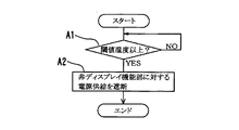
- FIG. 2 is a flowchart illustrating an example of power control by the vehicle power control device according to the first embodiment.
- FIG. 3 is a flowchart illustrating an example of power control by the vehicle power control device according to the second embodiment.
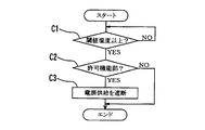
- FIG. 4 is a flowchart illustrating an example of power control by the vehicle power control device according to the third embodiment.
- a vehicle power supply control device 10 illustrated in FIG. 1 is configured with a control unit 11 as a main body, and is configured to drive various drive ICs based on a battery power supply “+ B” supplied from, for example, a 12V vehicle-mounted battery 12. .
- the vehicle power supply control device 10 is simply referred to as “power supply control device 10”.
- the power supply control device 10 can control the power interruption to each driving IC by appropriately controlling the opening and closing of the power supply line L.
- the control unit 11 is composed of a microcomputer mainly including a CPU (not shown), and controls the overall operation of the power supply control device 10. Moreover, the control part 11 implement
- the temperature detector 13 is an example of a temperature detector, and detects the temperature via a temperature detector such as a thermistor (not shown).
- the target region in which the temperature detection unit 13 detects the temperature may be the temperature inside the power supply control device 10 or the temperature around the power supply control device 10. Further, the temperature detected by the temperature detection unit 13 may be the temperature inside an in-vehicle display (not shown) mounted in the vehicle compartment or the temperature around the in-vehicle display.
- the determining unit 14 is an example of a determining unit, and determines whether or not the detected temperature detected by the temperature detecting unit 13 is equal to or higher than a predetermined threshold temperature T.
- the threshold temperature T can be appropriately changed and set. In this case, as the threshold temperature T, a temperature equal to or lower than the upper limit value of the operation guarantee temperature of the in-vehicle display is set.
- the operation-guaranteed temperature of the in-vehicle display is generally set in the range of -35 ° C to 65 ° C. Accordingly, in this case, the threshold temperature T is set to a temperature of 65 ° C. or lower which is the upper limit value of the operation guarantee temperature.
- the blocking unit 15 is an example of a blocking unit. When the determination unit 14 determines that the detected temperature of the temperature detection unit 13 is equal to or higher than a predetermined threshold temperature T, the power supply to a non-display function unit described later is cut off in detail. .
- the power supply control device 10 includes an in-vehicle display drive IC 21, a USB communication module drive IC 22 (USB: Universal Serial Bus), a Bluetooth communication module drive IC 23 (Bluetooth: registered trademark), a WiFi communication module drive IC 24, a CAN Various ICs such as communication module drive IC 25 (CAN: Controller Area Network), LIN communication module drive IC 26 (LIN: Local Interconnect Network), vehicle air conditioner drive IC 27, warning buzzer drive IC 28, vehicle camera drive IC 29, etc. Prepare.
- USB communication module drive IC 22 USB: Universal Serial Bus
- Bluetooth communication module drive IC 23 Bluetooth: registered trademark
- WiFi communication module drive IC 24 a CAN
- Various ICs such as communication module drive IC 25 (CAN: Controller Area Network), LIN communication module drive IC 26 (LIN: Local Interconnect Network), vehicle air conditioner drive IC 27, warning buzzer drive IC 28, vehicle camera drive IC 29, etc. Prepare.
- the in-vehicle display driving IC 21 operates based on a battery power source converted into a predetermined driving voltage by the DC / DC converter 31 and controls driving of the in-vehicle display.
- the USB communication module drive IC 22 operates based on the battery power source converted into a predetermined drive voltage by the DC / DC converter 32, and controls the drive of a communication module (not shown) that realizes USB communication.
- the Bluetooth communication module drive IC 23 operates based on the battery power converted into a predetermined drive voltage by the DC / DC converter 33, and controls driving of a communication module (not shown) that realizes Bluetooth communication.
- the WiFi communication module drive IC 24 operates based on the battery power converted into a predetermined drive voltage by the DC / DC converter 34, and controls the drive of a communication module (not shown) that realizes WiFi communication.
- the CAN communication module driving IC 25 operates based on a battery power source converted into a predetermined driving voltage by the DC / DC converter 35, and controls driving of a communication module (not shown) that realizes CAN communication.
- the LIN communication module driving IC 26 operates based on the battery power converted into a predetermined driving voltage by the DC / DC converter 36, and controls driving of a communication module (not shown) that realizes LIN communication.
- the in-vehicle air conditioner driving IC 27 operates based on a battery power source converted into a predetermined driving voltage by the DC / DC converter 37 and controls driving of an in-vehicle air conditioner (not shown).
- the warning buzzer driving IC 28 operates based on the battery power converted into a predetermined driving voltage by the DC / DC converter 38, and controls driving of a warning buzzer (not shown).
- the in-vehicle camera driving IC 29 operates based on a battery power source converted into a predetermined driving voltage by the DC / DC converter 39, and controls driving of an in-vehicle camera (not shown).
- the power supply control device 10 classifies these driving ICs 21 to 29 into two functional parts. That is, the power supply control device 10 includes the in-vehicle display driving IC 21 as an example of a display function unit having a display function for displaying various information on the in-vehicle display. In addition, the power supply control device 10 includes the driving ICs 22 to 29 as an example of a non-display function unit that performs functions other than the display function unit.
- the power supply control device 10 monitors the temperature detected by the temperature detector 13 and determines that the detected temperature is equal to or higher than the threshold temperature T (A1: YES), as a non-display function unit. The power supply to all the set drive ICs 22 to 29 is stopped. At this time, the power supply control device 10 does not stop the power supply to the in-vehicle display driving IC 21.
- the power supply to all the driving ICs 22 to 29 other than the in-vehicle display driving IC 21 is cut off at a high temperature at which the detected temperature is equal to or higher than the threshold temperature T. According to this configuration, it is possible to suppress the heat generation from the other driving ICs 22 to 29 while maintaining the power supply to the in-vehicle display driving IC 21. Therefore, it is possible to avoid a high temperature without degrading the display quality of the in-vehicle display.
- the temperature equal to or lower than the upper limit value of the operation-guaranteed temperature of the in-vehicle display is set as the threshold temperature T serving as a temperature determination reference.
- the power supply to the driving ICs 22 to 29 other than the in-vehicle display driving IC 21 can be cut off before the detected temperature reaches the upper limit value of the operation guarantee temperature of the in-vehicle display. Therefore, it is possible to avoid the temperature load exceeding the upper limit value of the operation guarantee temperature being applied to the in-vehicle display.
- the driving ICs 22 to 29 which are non-display function units are further classified. That is, among the driving ICs 22 to 29, the CAN communication module driving IC 25, the LIN communication module driving IC 26, the in-vehicle air conditioner driving IC 27, the warning buzzer driving IC 28, and the in-vehicle camera driving IC 29 have functions related to vehicle running safety. It is provided as an example of a traveling safety function unit.
- the power supply control device 10 monitors the temperature detected by the temperature detector 13 and determines that the detected temperature is equal to or higher than the threshold temperature T (B1: YES), as a non-display function unit. It is checked whether or not all the driving ICs 22 to 29 that have been set are set as travel safety function sections (B2). Then, the power supply control device 10 stops the power supply to the driving ICs 22 to 24 that are not set as the traveling safety function unit (B2: NO, B3). At this time, the power supply control device 10 does not stop the power supply to the driving ICs 25 to 29 set as the travel safety function unit among the non-display function units (B2: YES). Further, the power supply control device 10 does not stop power supply to the in-vehicle display driving IC 21.
- the power supply control device 10 at a high temperature where the detected temperature is equal to or higher than the threshold temperature T, the power supply to all the driving ICs 22 to 29 that are non-display function units is not cut off, but set as a travel safety function unit The power supply is stopped only for the driving ICs 22 to 24 which are not provided. According to the power supply control device 10, the power supply to the driving ICs 25 to 29 that are the traveling safety function units is continued even at high temperatures. According to this configuration, in addition to the in-vehicle display driving IC 21, it is possible to further suppress the heat generation from the other driving ICs 22 to 24 while maintaining the power supply to the travel safety function unit. Therefore, it is possible to avoid a high temperature without degrading the display quality of the in-vehicle display and without degrading the function related to traveling safety.
- the driving ICs 22 to 29 which are non-display function units are further classified. That is, among the drive ICs 22 to 29, the USB communication module drive IC 22 is provided as an example of a permission function unit that is permitted to shut off the power supply.
- the Bluetooth communication module driving IC 23 and the WiFi communication module driving IC 24 are provided as an example of a non-permitted function unit that is not permitted to shut off the power supply.
- the setting of the permission function unit and the non-permission function unit can be set, for example, when the power supply control device 10 is manufactured. If the Bluetooth communication function or the WiFi communication function is disabled, there is a concern that it may be inconvenient for the user. For this reason, in the present embodiment, the power supply to the Bluetooth communication module driving IC 23 and the WiFi communication module driving IC 24 is not permitted to be cut off even at high temperatures.
- the power supply control device 10 monitors the temperature detected by the temperature detector 13 and determines that the detected temperature is equal to or higher than the threshold temperature T (C1: YES), as a non-display function unit. It is confirmed whether or not all of the set driving ICs 22 to 29 are set as permission function sections (C2). Then, the power supply control device 10 stops the power supply to the driving IC 22 set as the permission function unit (C2: YES, C3). At this time, the power supply control device 10 does not stop the power supply to the driving ICs 23 and 24 set as the non-permission function units among the non-display function units (C2: NO). Further, the power supply control device 10 does not stop power supply to the in-vehicle display driving IC 21.
- the threshold temperature T C1: YES
- the power supply control device 10 at a high temperature where the detected temperature is equal to or higher than the threshold temperature T, the power supply to all the driving ICs 22 to 29 that are non-display function units is not cut off, but is set as a permission function unit. The power supply is stopped only for the driving IC 22. And according to the power supply control device 10, the power supply to the driving ICs 23 and 24 set as the non-permission function unit is continued even at high temperatures. According to this configuration, in addition to the in-vehicle display driving IC 21, heat generation from other driving ICs 22 can be suppressed while maintaining power supply to the non-permitted function unit. Therefore, it is possible to avoid a high temperature without degrading the display quality of the in-vehicle display and without degrading the convenience for the user.
- the permitted function unit and the non-permitted function unit are configured so that they can be set only when setting by the user is impossible, for example, during manufacturing.
- the permitted function unit and the non-permitted function unit are freely set by the user, for example, the number of non-permitted function units, that is, the number of function units whose power supply is not interrupted at high temperatures increases, and the effect of avoiding high temperature is impaired. It is because there is a risk of being.
- the user is allowed to freely allow a specific function IC and a specific function IC that has a function related to user convenience, such as a USB communication module drive IC 22, a Bluetooth communication module drive IC 23, a WiFi communication module drive IC 24, and the like. You may comprise so that the setting of a non-permission function part can be performed.
- the embodiments are not limited to the above-described embodiments, and the technical idea of the present disclosure can be applied to various embodiments.
- the functional units included in the vehicle power supply control device are not limited to the various driving ICs described above, and various functional units can be employed. Moreover, it is good also as a structure which continues the power supply with respect to both a driving
Landscapes
- Engineering & Computer Science (AREA)
- Mechanical Engineering (AREA)
- Electric Propulsion And Braking For Vehicles (AREA)
Abstract
車室内に搭載されたディスプレイに各種情報を表示するディスプレイ機能を担うディスプレイ機能部(21)および前記ディスプレイ機能部以外の機能を担う非ディスプレイ機能部(22~29)に対する電源供給を制御する車両用電源制御装置を提供する。車両用電源制御装置は、温度を検知する温度検知部(13)と、前記温度検知部が検知する検知温度が所定の閾値温度以上であるか否かを判定する判定部(14)と、前記判定部が前記検知温度が所定の閾値温度以上であると判定すると、前記非ディスプレイ機能部に対する電源供給を遮断する遮断部(15)と、を備える。
Description
本出願は、2015年1月15日に出願された日本国特許出願2015-5905号に基づくものであり、その開示をここに参照により援用する。
本開示は、車両用電源制御装置に関する。
近年、例えば高級車の車室内にはディスプレイが標準的に搭載されるようになっており、このディスプレイへの表示機能の高品質化が求められている。ところで、例えば炎天下においては、車室内は85℃近くにまで達し著しく高温となる。また、近年のディスプレイは、高機能化、多機能化が進んでおり、これらの機能を実現するために高電力を消費するICが搭載されている。そのため、これらの高電力ICからの発熱により高温化する傾向もある。
このように高温化が懸念される環境の中では、ディスプレイの性能が低下してしまうおそれがある。そのため、高温時であってもディスプレイの表示品質を維持するためには何らかの対策が必要である。例えば特許文献1には、ディスプレイの制御部の温度が所定値以上となった場合に、バックライトへの入力電力を減らす技術が開示されている。この技術によれば、バックライトの消費電力を減らすことで、それ以上の高温化を回避することが期待できる。
しかしながら、バックライトは、ディスプレイの表示機能に直結する機能部である。そのため、このバックライトの入力電力を減らしてしまうと、高温化の回避は図れるものの、ディスプレイの表示品質が低下してしまう。
そこで、本開示の目的の一つは、ディスプレイの表示品質の低下を招くことなく高温化を回避することができる車両用電源制御装置を提供することにある。
本開示の一例に係る車両用電源制御装置は、車室内に搭載されたディスプレイに各種情報を表示するディスプレイ機能を担うディスプレイ機能部に対する電源供給、および、ディスプレイ機能部以外の機能を担う非ディスプレイ機能部に対する電源供給を制御する車両用電源制御装置である。
車両用電源制御装置は、検知温度が所定の閾値温度以上である場合には、非ディスプレイ機能部に対する電源供給を遮断する。この構成によれば、ディスプレイ機能部への電源供給を維持しつつ、それ以外の非ディスプレイ機能部からの発熱を抑えることができる。従って、ディスプレイの表示品質の低下を招くことなく高温化を回避することができる。
具体的には、電源制御装置は、温度を検知する温度検知部と、前記温度検知部が検知する検知温度が所定の閾値温度以上であるか否かを判定する判定部と、前記判定部が前記検知温度が所定の閾値温度以上であると判定すると、前記非ディスプレイ機能部に対する電源供給を遮断する遮断部と、を備えるように構成されてもよい。
車両用電源制御装置は、検知温度が所定の閾値温度以上である場合には、非ディスプレイ機能部に対する電源供給を遮断する。この構成によれば、ディスプレイ機能部への電源供給を維持しつつ、それ以外の非ディスプレイ機能部からの発熱を抑えることができる。従って、ディスプレイの表示品質の低下を招くことなく高温化を回避することができる。
具体的には、電源制御装置は、温度を検知する温度検知部と、前記温度検知部が検知する検知温度が所定の閾値温度以上であるか否かを判定する判定部と、前記判定部が前記検知温度が所定の閾値温度以上であると判定すると、前記非ディスプレイ機能部に対する電源供給を遮断する遮断部と、を備えるように構成されてもよい。
本開示のついての上記および他の目的、特徴や利点は、添付図面を参照した下記の詳細な説明から、より明確になる。添付図面において、
図1は、第1実施形態に係る車両用電源制御装置の構成例を概略的に示すブロック図である。
図2は、第1実施形態に係る車両用電源制御装置による電源制御の一例を示すフローチャートである。
図3は、第2実施形態に係る車両用電源制御装置による電源制御の一例を示すフローチャートである。
図4は、第3実施形態に係る車両用電源制御装置による電源制御の一例を示すフローチャートである。
以下、車両用電源制御装置に係る複数の実施形態について図面を参照しながら説明する。なお、各実施形態において実質的に同一の要素には同一の符号を付し、説明を省略する。
(第1実施形態)
図1に例示する車両用電源制御装置10は、制御部11を主体として構成され、例えば12Vの車載バッテリ12から与えられるバッテリ電源「+B」に基づいて各種の駆動用ICを駆動する構成である。以下、車両用電源制御装置10を、単に「電源制御装置10」と称する。電源制御装置10は、電源供給ラインLの開路および閉路を適宜制御することにより、各駆動用ICに対する通断電をそれぞれ制御することが可能である。
図1に例示する車両用電源制御装置10は、制御部11を主体として構成され、例えば12Vの車載バッテリ12から与えられるバッテリ電源「+B」に基づいて各種の駆動用ICを駆動する構成である。以下、車両用電源制御装置10を、単に「電源制御装置10」と称する。電源制御装置10は、電源供給ラインLの開路および閉路を適宜制御することにより、各駆動用ICに対する通断電をそれぞれ制御することが可能である。
制御部11は、図示しないCPUを主体とするマイクロコンピュータで構成されており、電源制御装置10の動作全般を制御する。また、制御部11は、CPUにおいて制御プログラムを実行することにより、温度検知部13、判定部14、遮断部15をソフトウェアにより仮想的に実現する。なお、電源制御装置10は、温度検知部13、判定部14、遮断部15をハードウェアにより実装する構成としてもよい。
温度検知部13は、温度検知手段の一例であり、図示しないサーミスタなどからなる温度検知器を介して温度を検知する。なお、温度検知部13が温度を検知する対象領域は、電源制御装置10内部の温度であってもよいし、電源制御装置10周辺の温度であってもよい。また、温度検知部13が検知する温度は、車室内に搭載されている図示しない車載ディスプレイの内部の温度であってもよいし、車載ディスプレイ周辺の温度であってもよい。
判定部14は、判定手段の一例であり、温度検知部13が検知する検知温度が所定の閾値温度T以上であるか否かを判定する。閾値温度Tは、適宜変更して設定可能である。この場合、閾値温度Tとして、車載ディスプレイの動作保障温度の上限値以下の温度が設定されている。車載ディスプレイの動作保障温度は、一般的に-35℃~65℃の範囲で設定される。従って、この場合、閾値温度Tとしては、動作保障温度の上限値である65℃以下の温度が設定される。遮断部15は、遮断手段の一例であり、判定部14が温度検知部13の検知温度が所定の閾値温度T以上であると判定すると、詳しくは後述する非ディスプレイ機能部に対する電源供給を遮断する。
電源制御装置10は、この場合、車載ディスプレイ駆動用IC21、USB通信モジュール駆動用IC22(USB:Universal Serial Bus)、Bluetooth通信モジュール駆動用IC23(Bluetooth:登録商標)、WiFi通信モジュール駆動用IC24、CAN通信モジュール駆動用IC25(CAN:Controller Area Network)、LIN通信モジュール駆動用IC26(LIN:Local Interconnect Network)、車載エアコン駆動用IC27、警告ブザー駆動用IC28、車載カメラ駆動用IC29などといった各種のICを備える。
車載ディスプレイ駆動用IC21は、DC/DCコンバータ31により所定の駆動電圧に変換されたバッテリ電源に基づいて動作し、車載ディスプレイの駆動を制御する。USB通信モジュール駆動用IC22は、DC/DCコンバータ32により所定の駆動電圧に変換されたバッテリ電源に基づいて動作し、USB通信を実現する図示しない通信モジュールの駆動を制御する。Bluetooth通信モジュール駆動用IC23は、DC/DCコンバータ33により所定の駆動電圧に変換されたバッテリ電源に基づいて動作し、Bluetooth通信を実現する図示しない通信モジュールの駆動を制御する。
WiFi通信モジュール駆動用IC24は、DC/DCコンバータ34により所定の駆動電圧に変換されたバッテリ電源に基づいて動作し、WiFi通信を実現する図示しない通信モジュールの駆動を制御する。CAN通信モジュール駆動用IC25は、DC/DCコンバータ35により所定の駆動電圧に変換されたバッテリ電源に基づいて動作し、CAN通信を実現する図示しない通信モジュールの駆動を制御する。LIN通信モジュール駆動用IC26は、DC/DCコンバータ36により所定の駆動電圧に変換されたバッテリ電源に基づいて動作し、LIN通信を実現する図示しない通信モジュールの駆動を制御する。
車載エアコン駆動用IC27は、DC/DCコンバータ37により所定の駆動電圧に変換されたバッテリ電源に基づいて動作し、図示しない車載エアコンの駆動を制御する。警告ブザー駆動用IC28は、DC/DCコンバータ38により所定の駆動電圧に変換されたバッテリ電源に基づいて動作し、図示しない警告ブザーの駆動を制御する。車載カメラ駆動用IC29は、DC/DCコンバータ39により所定の駆動電圧に変換されたバッテリ電源に基づいて動作し、図示しない車載カメラの駆動を制御する。
電源制御装置10は、これら駆動用IC21~29を2つの機能部に分類している。即ち、電源制御装置10は、車載ディスプレイ駆動用IC21を、車載ディスプレイに各種情報を表示するディスプレイ機能を担うディスプレイ機能部の一例として備えている。また、電源制御装置10は、駆動用IC22~29を、ディスプレイ機能部以外の機能を担う非ディスプレイ機能部の一例として備えている。
次に、電源制御装置10による電源制御の一例について説明する。図2に例示するように、電源制御装置10は、温度検知部13による検知温度を監視しており、検知温度が閾値温度T以上であると判定すると(A1:YES)、非ディスプレイ機能部として設定されている全ての駆動用IC22~29に対する電源供給を停止する。このとき、電源制御装置10は、車載ディスプレイ駆動用IC21に対する電源供給は停止しない。
電源制御装置10によれば、検知温度が閾値温度T以上となる高温時には、車載ディスプレイ駆動用IC21以外の全ての駆動用IC22~29に対する電源供給を遮断する。この構成によれば、車載ディスプレイ駆動用IC21への電源供給を維持しつつ、それ以外の駆動用IC22~29からの発熱を抑えることができる。従って、車載ディスプレイの表示品質の低下を招くことなく高温化を回避することができる。
また、電源制御装置10によれば、温度判定の基準となる閾値温度Tとして、車載ディスプレイの動作保障温度の上限値以下の温度が設定されている。この構成によれば、検知温度が車載ディスプレイの動作保障温度の上限値に到達する前に、車載ディスプレイ駆動用IC21以外の駆動用IC22~29への電源供給を遮断できる。従って、車載ディスプレイに動作保障温度の上限値を超える温度負荷がかかってしまうことを回避できる。
(第2実施形態)
本実施形態では、非ディスプレイ機能部である駆動用IC22~29がさらに細かく分類されている。即ち、駆動用IC22~29のうち、CAN通信モジュール駆動用IC25、LIN通信モジュール駆動用IC26、車載エアコン駆動用IC27、警告ブザー駆動用IC28、車載カメラ駆動用IC29は、車両の走行安全に関する機能を担う走行安全機能部の一例として備えられている。
本実施形態では、非ディスプレイ機能部である駆動用IC22~29がさらに細かく分類されている。即ち、駆動用IC22~29のうち、CAN通信モジュール駆動用IC25、LIN通信モジュール駆動用IC26、車載エアコン駆動用IC27、警告ブザー駆動用IC28、車載カメラ駆動用IC29は、車両の走行安全に関する機能を担う走行安全機能部の一例として備えられている。
次に、本実施形態による電源制御の一例について説明する。図3に例示するように、電源制御装置10は、温度検知部13による検知温度を監視しており、検知温度が閾値温度T以上であると判定すると(B1:YES)、非ディスプレイ機能部として設定されている全ての駆動用IC22~29について、それぞれ走行安全機能部として設定されているか否かを確認する(B2)。そして、電源制御装置10は、走行安全機能部として設定されていない駆動用IC22~24に対する電源供給を停止する(B2:NO、B3)。このとき、電源制御装置10は、非ディスプレイ機能部のうち走行安全機能部として設定されている駆動用IC25~29に対する電源供給は停止しない(B2:YES)。また、電源制御装置10は、車載ディスプレイ駆動用IC21に対する電源供給は停止しない。
電源制御装置10によれば、検知温度が閾値温度T以上となる高温時において、非ディスプレイ機能部である全ての駆動用IC22~29に対する電源供給を遮断するのではなく、走行安全機能部として設定されていない駆動用IC22~24に限定して電源供給を停止するようにした。そして、電源制御装置10によれば、高温時においても走行安全機能部である駆動用IC25~29に対する電源供給は継続する。この構成によれば、車載ディスプレイ駆動用IC21に加えて、さらに走行安全機能部への電源供給を維持しつつ、それ以外の駆動用IC22~24からの発熱を抑えることができる。従って、車載ディスプレイの表示品質の低下を招くことなく、さらに走行安全に関する機能の低下を招くことなく、高温化を回避することができる。
(第3実施形態)
本実施形態では、非ディスプレイ機能部である駆動用IC22~29がさらに細かく分類されている。即ち、駆動用IC22~29のうち、USB通信モジュール駆動用IC22は、電源供給の遮断が許可されている許可機能部の一例として備えられている。一方、Bluetooth通信モジュール駆動用IC23およびWiFi通信モジュール駆動用IC24は、電源供給の遮断が許可されていない非許可機能部の一例として備えられている。許可機能部および非許可機能部の設定は、例えば電源制御装置10の製造時に設定可能である。Bluetooth通信機能やWiFi通信機能が使用不能になるとユーザにとって不便となることが懸念される。そのため、本実施形態では、高温時であっても、Bluetooth通信モジュール駆動用IC23およびWiFi通信モジュール駆動用IC24に対する電源供給の遮断が不許可となる設定がなされている。
本実施形態では、非ディスプレイ機能部である駆動用IC22~29がさらに細かく分類されている。即ち、駆動用IC22~29のうち、USB通信モジュール駆動用IC22は、電源供給の遮断が許可されている許可機能部の一例として備えられている。一方、Bluetooth通信モジュール駆動用IC23およびWiFi通信モジュール駆動用IC24は、電源供給の遮断が許可されていない非許可機能部の一例として備えられている。許可機能部および非許可機能部の設定は、例えば電源制御装置10の製造時に設定可能である。Bluetooth通信機能やWiFi通信機能が使用不能になるとユーザにとって不便となることが懸念される。そのため、本実施形態では、高温時であっても、Bluetooth通信モジュール駆動用IC23およびWiFi通信モジュール駆動用IC24に対する電源供給の遮断が不許可となる設定がなされている。
次に、本実施形態による電源制御の一例について説明する。図4に例示するように、電源制御装置10は、温度検知部13による検知温度を監視しており、検知温度が閾値温度T以上であると判定すると(C1:YES)、非ディスプレイ機能部として設定されている全ての駆動用IC22~29について、それぞれ許可機能部として設定されているか否かを確認する(C2)。そして、電源制御装置10は、許可機能部として設定されている駆動用IC22に対する電源供給を停止する(C2:YES、C3)。このとき、電源制御装置10は、非ディスプレイ機能部のうち非許可機能部として設定されている駆動用IC23,24に対する電源供給は停止しない(C2:NO)。また、電源制御装置10は、車載ディスプレイ駆動用IC21に対する電源供給は停止しない。
電源制御装置10によれば、検知温度が閾値温度T以上となる高温時において、非ディスプレイ機能部である全ての駆動用IC22~29に対する電源供給を遮断するのではなく、許可機能部として設定されている駆動用IC22に限定して電源供給を停止するようにした。そして、電源制御装置10によれば、高温時においても非許可機能部として設定されている駆動用IC23,24に対する電源供給は継続する。この構成によれば、車載ディスプレイ駆動用IC21に加えて、さらに非許可機能部への電源供給を維持しつつ、それ以外の駆動用IC22からの発熱を抑えることができる。従って、車載ディスプレイの表示品質の低下を招くことなく、さらにユーザの利便性の低下を招くことなく、高温化を回避することができる。
なお、許可機能部および非許可機能部の設定は、例えば製造時などユーザによる設定が不可能なときに限って行えるように構成することが好ましい。ユーザにより自由に許可機能部および非許可機能部の設定がなされると、例えば非許可機能部の数、つまり高温時に電源供給が遮断されない機能部の数が多くなって高温化回避の効果が損なわれるおそれがあるからである。但し、例えば、USB通信モジュール駆動用IC22、Bluetooth通信モジュール駆動用IC23、WiFi通信モジュール駆動用IC24などといったユーザの利便性に関する機能を担う特定の駆動用ICに限ってユーザが自由に許可機能部および非許可機能部の設定をできるように構成してもよい。
(その他の実施形態)
実施形態は、上述した実施形態に限定されるものではなく、本開示の技術的思想は、種々の実施形態に適用可能である。例えば、車両用電源制御装置が備える機能部は、上述した各種の駆動用ICに限られるものではなく、種々の機能部を採用することができる。また、第2実施形態と第3実施形態とを組み合わせて、高温時であっても走行安全機能部および非許可機能部の双方に対する電源供給を継続する構成としてもよい。
実施形態は、上述した実施形態に限定されるものではなく、本開示の技術的思想は、種々の実施形態に適用可能である。例えば、車両用電源制御装置が備える機能部は、上述した各種の駆動用ICに限られるものではなく、種々の機能部を採用することができる。また、第2実施形態と第3実施形態とを組み合わせて、高温時であっても走行安全機能部および非許可機能部の双方に対する電源供給を継続する構成としてもよい。
Claims (4)
- 車室内に搭載されたディスプレイに各種情報を表示するディスプレイ機能を担うディスプレイ機能部(21)および前記ディスプレイ機能部以外の機能を担う非ディスプレイ機能部(22~29)に対する電源供給を制御する車両用電源制御装置であって、
温度を検知する温度検知部(13)と、
前記温度検知部が検知する検知温度が所定の閾値温度以上であるか否かを判定する判定部(14)と、
前記判定部が前記検知温度が所定の閾値温度以上であると判定すると、前記非ディスプレイ機能部に対する電源供給を遮断する遮断部(15)と、
を備える車両用電源制御装置。 - 前記閾値温度として、前記ディスプレイの動作保障温度の上限値以下の温度が設定されている請求項1に記載の車両用電源制御装置。
- 前記非ディスプレイ機能部には、車両の走行安全に関する機能を担う走行安全機能部(25~29)が含まれ、
前記遮断部は、前記判定部が前記検知温度が所定の閾値温度以上であると判定した場合であっても、前記走行安全機能部に対する電源供給を継続する請求項1または2に記載の車両用電源制御装置。 - 前記非ディスプレイ機能部には、電源供給の遮断が許可されている許可機能部(22)と、電源供給の遮断が許可されていない非許可機能部(23,24)と、が含まれ、
前記遮断部は、前記判定部が前記検知温度が所定の閾値温度以上であると判定すると、前記許可機能部に対する電源供給を遮断する請求項1から3の何れか1項に記載の車両用電源制御装置。
Applications Claiming Priority (2)
| Application Number | Priority Date | Filing Date | Title |
|---|---|---|---|
| JP2015005905A JP2016132261A (ja) | 2015-01-15 | 2015-01-15 | 車両用電源制御装置 |
| JP2015-005905 | 2015-01-15 |
Publications (1)
| Publication Number | Publication Date |
|---|---|
| WO2016114112A1 true WO2016114112A1 (ja) | 2016-07-21 |
Family
ID=56405664
Family Applications (1)
| Application Number | Title | Priority Date | Filing Date |
|---|---|---|---|
| PCT/JP2016/000060 Ceased WO2016114112A1 (ja) | 2015-01-15 | 2016-01-07 | 車両用電源制御装置 |
Country Status (2)
| Country | Link |
|---|---|
| JP (1) | JP2016132261A (ja) |
| WO (1) | WO2016114112A1 (ja) |
Cited By (1)
| Publication number | Priority date | Publication date | Assignee | Title |
|---|---|---|---|---|
| CN113475001A (zh) * | 2019-02-28 | 2021-10-01 | 株式会社电装 | 车辆用无线通信装置 |
Citations (3)
| Publication number | Priority date | Publication date | Assignee | Title |
|---|---|---|---|---|
| JP2005206085A (ja) * | 2004-01-23 | 2005-08-04 | Sumitomo Electric Ind Ltd | 電力分配システム、電力分配器、及びブレーキ装置 |
| JP2007015413A (ja) * | 2005-07-05 | 2007-01-25 | Fujitsu Ten Ltd | 表示部付き電子機器 |
| WO2015002258A1 (ja) * | 2013-07-04 | 2015-01-08 | 日本精機株式会社 | 車両用表示装置 |
-
2015
- 2015-01-15 JP JP2015005905A patent/JP2016132261A/ja active Pending
-
2016
- 2016-01-07 WO PCT/JP2016/000060 patent/WO2016114112A1/ja not_active Ceased
Patent Citations (3)
| Publication number | Priority date | Publication date | Assignee | Title |
|---|---|---|---|---|
| JP2005206085A (ja) * | 2004-01-23 | 2005-08-04 | Sumitomo Electric Ind Ltd | 電力分配システム、電力分配器、及びブレーキ装置 |
| JP2007015413A (ja) * | 2005-07-05 | 2007-01-25 | Fujitsu Ten Ltd | 表示部付き電子機器 |
| WO2015002258A1 (ja) * | 2013-07-04 | 2015-01-08 | 日本精機株式会社 | 車両用表示装置 |
Cited By (2)
| Publication number | Priority date | Publication date | Assignee | Title |
|---|---|---|---|---|
| CN113475001A (zh) * | 2019-02-28 | 2021-10-01 | 株式会社电装 | 车辆用无线通信装置 |
| CN113475001B (zh) * | 2019-02-28 | 2023-03-28 | 株式会社电装 | 车辆用无线通信装置 |
Also Published As
| Publication number | Publication date |
|---|---|
| JP2016132261A (ja) | 2016-07-25 |
Similar Documents
| Publication | Publication Date | Title |
|---|---|---|
| US20150273975A1 (en) | Reverse flow automotive ventilation system | |
| US9533549B2 (en) | System and method for controlling heating modes for hybrid electric vehicle (HEV) | |
| CN205189604U (zh) | 一种汽车天窗智能开闭控制系统 | |
| US8892300B2 (en) | System and method for providing power to an HVAC unit when the vehicle has a low state of charge | |
| WO2019013314A1 (ja) | 空調制御装置 | |
| KR20180120952A (ko) | 배터리 냉각 제어 장치 및 방법, 그리고 차량 시스템 | |
| CN105082926A (zh) | 汽车空调启停控制系统及其控制方法 | |
| JP2015074243A (ja) | 車両 | |
| CN105818639A (zh) | 车载空调控制方法及装置 | |
| CN115973098A (zh) | 汽车空调除雾方法、除雾装置、电子设备及存储介质 | |
| KR101527052B1 (ko) | 자동차의 실내온도 통합제어 방법 | |
| WO2016114112A1 (ja) | 車両用電源制御装置 | |
| CN117261600A (zh) | 增程式汽车的控制方法、装置、电子设备及可读存储介质 | |
| JP5985814B2 (ja) | 車両の高電圧バッテリー冷却制御方法 | |
| JP6730809B2 (ja) | 電源制御装置、これを含む車両、及び車両の制御方法 | |
| CN103171398A (zh) | 车用空调器的控制方法和控制器 | |
| US9994086B2 (en) | Main semiconductor device for controlling air conditioner, and air conditioner of vehicle system having the same | |
| CN115716396A (zh) | 车辆空调内外循环自动控制方法、装置及相关设备 | |
| CN205344704U (zh) | 一种用于汽车的全视角反光镜 | |
| US12164360B2 (en) | Vehicular advertisement display device and vehicle | |
| CN202783022U (zh) | 一种汽车散热装置 | |
| CN207902096U (zh) | 一种双模式汽车空调系统 | |
| CN115402049B (zh) | 车载空调器控制方法、装置、存储介质及车载空调器 | |
| JP7225937B2 (ja) | 空調制御システム | |
| CN204923555U (zh) | 一种汽车贴膜 |
Legal Events
| Date | Code | Title | Description |
|---|---|---|---|
| 121 | Ep: the epo has been informed by wipo that ep was designated in this application |
Ref document number: 16737183 Country of ref document: EP Kind code of ref document: A1 |
|
| NENP | Non-entry into the national phase |
Ref country code: DE |
|
| 122 | Ep: pct application non-entry in european phase |
Ref document number: 16737183 Country of ref document: EP Kind code of ref document: A1 |