WO2016113927A1 - 清掃具 - Google Patents
清掃具 Download PDFInfo
- Publication number
- WO2016113927A1 WO2016113927A1 PCT/JP2015/068404 JP2015068404W WO2016113927A1 WO 2016113927 A1 WO2016113927 A1 WO 2016113927A1 JP 2015068404 W JP2015068404 W JP 2015068404W WO 2016113927 A1 WO2016113927 A1 WO 2016113927A1
- Authority
- WO
- WIPO (PCT)
- Prior art keywords
- cleaning
- guide
- insertion end
- cleaning tool
- gap
- Prior art date
Links
- 238000004140 cleaning Methods 0.000 title claims abstract description 177
- 238000003780 insertion Methods 0.000 claims abstract description 102
- 230000037431 insertion Effects 0.000 claims abstract description 102
- 229920001971 elastomer Polymers 0.000 claims abstract description 26
- 239000000806 elastomer Substances 0.000 claims abstract description 26
- 238000005452 bending Methods 0.000 claims abstract description 7
- 230000002093 peripheral effect Effects 0.000 claims description 14
- 210000004209 hair Anatomy 0.000 claims description 9
- 230000005489 elastic deformation Effects 0.000 claims description 6
- 238000006073 displacement reaction Methods 0.000 abstract description 11
- 230000007423 decrease Effects 0.000 description 6
- 238000000605 extraction Methods 0.000 description 4
- -1 polypropylene Polymers 0.000 description 4
- 239000000835 fiber Substances 0.000 description 3
- 239000004743 Polypropylene Substances 0.000 description 2
- PPBRXRYQALVLMV-UHFFFAOYSA-N Styrene Chemical compound C=CC1=CC=CC=C1 PPBRXRYQALVLMV-UHFFFAOYSA-N 0.000 description 2
- 230000001771 impaired effect Effects 0.000 description 2
- 239000000463 material Substances 0.000 description 2
- 238000000034 method Methods 0.000 description 2
- 238000012986 modification Methods 0.000 description 2
- 230000004048 modification Effects 0.000 description 2
- 229920001155 polypropylene Polymers 0.000 description 2
- 229920003002 synthetic resin Polymers 0.000 description 2
- 239000000057 synthetic resin Substances 0.000 description 2
- 229930182556 Polyacetal Natural products 0.000 description 1
- 239000004793 Polystyrene Substances 0.000 description 1
- 229920000122 acrylonitrile butadiene styrene Polymers 0.000 description 1
- 150000001336 alkenes Chemical class 0.000 description 1
- 230000003670 easy-to-clean Effects 0.000 description 1
- 230000002708 enhancing effect Effects 0.000 description 1
- 210000003128 head Anatomy 0.000 description 1
- 210000000214 mouth Anatomy 0.000 description 1
- JRZJOMJEPLMPRA-UHFFFAOYSA-N olefin Natural products CCCCCCCC=C JRZJOMJEPLMPRA-UHFFFAOYSA-N 0.000 description 1
- 229920001707 polybutylene terephthalate Polymers 0.000 description 1
- 229920000515 polycarbonate Polymers 0.000 description 1
- 239000004417 polycarbonate Substances 0.000 description 1
- 229920000728 polyester Polymers 0.000 description 1
- 229920000139 polyethylene terephthalate Polymers 0.000 description 1
- 239000005020 polyethylene terephthalate Substances 0.000 description 1
- 229920006324 polyoxymethylene Polymers 0.000 description 1
- 229920002223 polystyrene Polymers 0.000 description 1
- 229910052710 silicon Inorganic materials 0.000 description 1
- 239000010703 silicon Substances 0.000 description 1
Images


Classifications
-
- B—PERFORMING OPERATIONS; TRANSPORTING
- B08—CLEANING
- B08B—CLEANING IN GENERAL; PREVENTION OF FOULING IN GENERAL
- B08B1/00—Cleaning by methods involving the use of tools
- B08B1/10—Cleaning by methods involving the use of tools characterised by the type of cleaning tool
- B08B1/14—Wipes; Absorbent members, e.g. swabs or sponges
- B08B1/145—Swabs
-
- A—HUMAN NECESSITIES
- A46—BRUSHWARE
- A46D—MANUFACTURE OF BRUSHES
- A46D1/00—Bristles; Selection of materials for bristles
- A46D1/02—Bristles details
- A46D1/0253—Bristles having a shape which is not a straight line, e.g. curved, "S", hook, loop
-
- A—HUMAN NECESSITIES
- A46—BRUSHWARE
- A46B—BRUSHES
- A46B3/00—Brushes characterised by the way in which the bristles are fixed or joined in or on the brush body or carrier
- A46B3/04—Brushes characterised by the way in which the bristles are fixed or joined in or on the brush body or carrier by mouldable materials, e.g. metals, cellulose derivatives, plastics
-
- A—HUMAN NECESSITIES
- A47—FURNITURE; DOMESTIC ARTICLES OR APPLIANCES; COFFEE MILLS; SPICE MILLS; SUCTION CLEANERS IN GENERAL
- A47L—DOMESTIC WASHING OR CLEANING; SUCTION CLEANERS IN GENERAL
- A47L25/00—Domestic cleaning devices not provided for in other groups of this subclass
-
- B—PERFORMING OPERATIONS; TRANSPORTING
- B08—CLEANING
- B08B—CLEANING IN GENERAL; PREVENTION OF FOULING IN GENERAL
- B08B1/00—Cleaning by methods involving the use of tools
-
- B—PERFORMING OPERATIONS; TRANSPORTING
- B08—CLEANING
- B08B—CLEANING IN GENERAL; PREVENTION OF FOULING IN GENERAL
- B08B1/00—Cleaning by methods involving the use of tools
- B08B1/10—Cleaning by methods involving the use of tools characterised by the type of cleaning tool
- B08B1/12—Brushes
-
- B—PERFORMING OPERATIONS; TRANSPORTING
- B08—CLEANING
- B08B—CLEANING IN GENERAL; PREVENTION OF FOULING IN GENERAL
- B08B1/00—Cleaning by methods involving the use of tools
- B08B1/10—Cleaning by methods involving the use of tools characterised by the type of cleaning tool
- B08B1/14—Wipes; Absorbent members, e.g. swabs or sponges
- B08B1/143—Wipes
-
- B—PERFORMING OPERATIONS; TRANSPORTING
- B08—CLEANING
- B08B—CLEANING IN GENERAL; PREVENTION OF FOULING IN GENERAL
- B08B1/00—Cleaning by methods involving the use of tools
- B08B1/10—Cleaning by methods involving the use of tools characterised by the type of cleaning tool
- B08B1/16—Rigid blades, e.g. scrapers; Flexible blades, e.g. wipers
- B08B1/165—Scrapers
-
- A—HUMAN NECESSITIES
- A46—BRUSHWARE
- A46B—BRUSHES
- A46B2200/00—Brushes characterized by their functions, uses or applications
- A46B2200/30—Brushes for cleaning or polishing
- A46B2200/3073—Brush for cleaning specific unusual places not otherwise covered, e.g. gutters, golf clubs, tops of tin cans, corners
Definitions
- the present invention relates to a cleaning tool.
- Patent Document 1 discloses a cleaning tool including a shaft portion and a fiber lump (cleaning portion) attached to the tip portion of the shaft portion.
- the cleaning unit is formed by compressing a predetermined amount of fibers.
- an elastomer is known as a material that can be used for forming a cleaning portion for cleaning minute gaps without causing the problem of fuzzing.
- the cleaning part formed of this elastomer does not cause fuzz and effectively removes dirt in the minute gaps by friction generated between the cleaning part and the object to be cleaned.
- the improvement of the insertion property of the cleaning portion into the minute gap is insufficient. Specifically, if the tip of the cleaning unit comes into contact with the object to be cleaned when the cleaning unit is inserted into a minute gap, the depth of the cleaning unit can be further increased by inserting the cleaning unit toward the back of the gap. An operation for changing the insertion direction (the posture of the shaft portion) with respect to the gap of the cleaning portion is required so that the insertion into the space is allowed. Since this operation is required every time the tip of the cleaning unit comes into contact with the object to be cleaned, it is very difficult to insert the cleaning unit to the back of the gap. This problem is particularly noticeable when the adjustment range of the posture of the shaft portion is limited, such as operation of the shaft portion in a narrow space.
- An object of the present invention is to provide a cleaning tool capable of easily inserting a cleaning portion to the back of a minute gap.
- a cleaning tool is a cleaning tool for cleaning a minute gap formed between objects to be cleaned adjacent to each other, and extends in a specific direction and can be inserted into the gap.
- a shaft portion having a shape and having an insertion end portion formed at one end in the specific direction and a base end portion formed at the other end in the specific direction, and having a hardness lower than the hardness of the shaft portion
- a cleaning portion that is made of an elastomer includes a portion including the insertion end portion, and covers a portion of the shaft portion having a dimension equal to or smaller than the axial dimension of the shaft portion, and is capable of cleaning the gap.
- the protruding dimension is equal to or greater than the thickness of the cleaning unit main body, and has a shape that can be elastically deformed so as to be displaced in the axis orthogonal direction with respect to the insertion end.
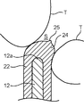
- FIG. 2 is a cross-sectional view taken along the line II-II shown in FIG. It is a figure which shows the outline of a press tester. It is a figure which shows the outline of the insertion initial stage of the cleaning part to the clearance gap between mutually adjacent to-be-cleaned objects. It is a figure which shows the outline of the insertion middle stage of the cleaning part to the clearance gap between mutually adjacent to-be-cleaned objects. It is sectional drawing which shows the modification of a cleaning part.
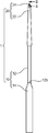
- a cleaning tool 1 according to an embodiment of the present invention will be described with reference to FIGS.
- the cleaning tool 1 is for cleaning minute gaps (such as gaps between keys on the keyboard or gaps between back teeth) formed between objects to be cleaned T (see FIGS. 4 and 5) adjacent to each other.
- the cleaning tool 1 of the present embodiment includes a base 10 and a cleaning part 20 made of an elastomer having a hardness lower than the hardness of the base 10.
- the base 10 is made of a synthetic resin such as polypropylene.
- the base 10 is preferably formed of polypropylene from the viewpoint that moderate elasticity is obtained in the base 10 and insertion into the gap is enhanced, but ABS, polycarbonate, polybutylene terephthalate, polyethylene terephthalate, polystyrene, polyacetal Or a synthetic resin such as As the elastomer, a styrene elastomer is preferably used. However, silicon, an olefin elastomer, a polyester elastomer, or the like may be used as the elastomer.
- the base portion 10 includes a shaft portion 12 having a shape extending linearly along a specific direction (vertical direction in FIG. 1), and a grip portion 14.
- the shaft portion 12 has a shape that can be inserted into the minute gap S (see FIG. 4).
- the shaft portion 12 has an insertion end portion 12a formed at one end in the specific direction and a base end portion 12b formed at the other end in the specific direction.
- the shaft portion 12 has a shape that can be bent and deformed so that the insertion end portion 12a is displaced in an axis orthogonal direction (left-right direction in FIG. 1) orthogonal to the axial direction of the shaft portion 12 with the base end portion 12b as a fulcrum.
- the shaft portion 12 is formed in a substantially cylindrical shape.
- the shaft portion 12 has a shape that gradually and slightly decreases the outer diameter of the shaft portion 12 from the base end portion 12b toward the insertion end portion 12a.
- the insertion end 12a is formed in a hemispherical shape that curves so as to protrude outward in the axial direction.
- the axial dimension of the shaft portion 12 is set to 29 mm
- the diameter of the base end portion 12b is set to 1.2 mm.
- the radius of the insertion end 12a is set to 0.27 mm.
- the grip 14 is a part gripped by a person.
- the grip portion 14 is connected to the base end portion 12 b of the shaft portion 12.
- the grip portion 14 is formed in a columnar shape having an outer diameter that is slightly larger than the outer diameter of the shaft portion 12.
- the shape of the gripping part 14 is not limited to this.
- the cleaning part 20 has a shape that includes the insertion end part 12a and covers a part of the shaft part 12 that has a dimension equal to or smaller than the dimension of the shaft part 12 in the axial direction and can clean the gap S.
- the cleaning portion 20 has a shape that covers a portion of the shaft portion 12 that continuously extends from the insertion end portion 12a along the direction from the insertion end portion 12a to the base end portion 12b.
- the axial dimension of the cleaning unit 20 is set to 15.4 mm.
- the cleaning unit 20 includes a cleaning unit main body 22 and a guide unit 24.
- the cleaning part main body 22 has a shape that covers the outer peripheral surface of the shaft part 12 including the insertion end part 12a.
- the cleaning unit main body 22 has a cylindrical outer peripheral surface.
- the cleaning unit main body 22 includes a first covering portion 22 a that covers the outer peripheral surface of the shaft portion 12 other than the insertion end portion 12 a and a first covering portion that covers the outer peripheral surface of the insertion end portion 12 a. 2 covering portion 22b.
- the thickness (dimension in the left-right direction in FIG. 2) t1 of the first covering portion 22a is set to 0.10 mm.
- the second covering portion 22b has a shape that gradually increases in thickness as it is spaced outward from the first covering portion 22a in the axial direction.
- the guide portion 24 has a shape that protrudes outward in the axial direction from the insertion end portion 12a and guides the insertion of the cleaning portion main body 22 into the gap S.
- the guide portion 24 has a shape that can be elastically deformed in the direction perpendicular to the axis with respect to the insertion end portion 12a.
- the protruding dimension t2 of the guide portion 24 from the insertion end portion 12a is set larger than the thickness t1 of the first covering portion 22a.
- the protrusion dimension t2 is preferably set to be not less than 3 times and not more than 10 times the thickness t1 of the first covering portion 22a.
- the protruding dimension t2 is set to be not less than 3 times and not more than 5 times the thickness t1 of the first covering portion 22a. Furthermore, it is preferable that the protruding dimension t2 is set to be not less than 0.6 times and not more than 4 times the diameter d of the insertion end portion 12a (1.1 times to not more than 8 times the radius of the insertion end portion 12a). In the present embodiment, the protrusion dimension t2 is set to four times the thickness t1 of the first covering portion 22a, that is, 0.40 mm. This value is about 1.5 times the radius of the insertion end 12a.
- the section of the guide portion 24 that is in contact with the insertion end portion 12a at the surface orthogonal to the axial direction is formed in a circular shape having the same radius as that of the tip portion of the second covering portion 22b.
- the guide portion 24 is formed in a hemispherical shape that curves so as to protrude outward in the axial direction. That is, the protrusion dimension t2 is set to a value equal to the radius of the guide portion 24.
- a minute protrusion 25 is connected to the tip of the guide portion 24.
- the minute protrusion 25 has a shape that protrudes outward in the axial direction from the tip of the guide portion 24.
- the microprotrusion 25 is formed in a conical shape.
- the outer diameter of the connection portion between the minute protrusion 25 and the guide portion 24 is set smaller than the outer diameter of the connection portion between the guide portion 24 and the second covering portion 22b (the radius of the guide portion 24).
- the dimension in the axial direction of the minute protrusion 25 is set smaller than the protrusion dimension t2 of the guide portion 24. Note that the minute protrusions 25 may be omitted.
- the guide in a state in which a portion of the cleaning tool 1 that is 10 mm away from the distal end of the guide portion 24 toward the base end side is fixed, the guide is accompanied by elastic deformation of the guide portion 24 and bending deformation of the shaft portion 12.
- the pressing force required to press the guide portion 24 from the insertion end portion 12a side toward the base end portion 12b side until the portion 24 is displaced by 5.0 mm in the axial direction is 1.0 N or more and 8.0 N or less.
- the Shore hardness of the elastomer is set.
- the shore hardness of the elastomer is set so that the pressing force is 3.0 N or more and 7.0 N or less, and more preferably, the pressing force is 4.0 N or more and 7.0 N or less. Is done.
- the elastomer those having a Shore hardness of A0 to A50 can be used, and in the present embodiment, those having a Shore hardness of A40 are used.
- the pressing force is measured by a pressing tester 30 shown in FIG.
- the press testing machine 30 includes a fixing base 32 that can fix the cleaning tool 1 and a pressing portion 34 that can press the cleaning tool 1 fixed to the fixing base 32.
- the pressing portion 34 is disposed vertically above the fixed base 32 and is configured to be able to press the cleaning tool 1 fixed to the fixed base 32 vertically downward.
- the cleaning tool 1 is fixed to the fixing base 32 in a posture in which the direction from the gripping portion 14 toward the guide portion 24 is vertically upward. Specifically, as shown in FIG. 3, the entire part of the cleaning tool 1 that is separated by 10 mm or more from the distal end of the guide portion 24 toward the base end portion 12 b side is fixed by a fixing base 32.
- the cleaning tool 1 is pressed vertically downward by the pressing portion 34.
- the pressing part 34 is displaced 5.0 mm vertically downward toward the fixed base 32 from a state in which the lower surface of the pressing part 34 is in contact with the guide part 24.
- the guide portion 24 is displaced by 5.0 mm in the axial direction while accompanying elastic deformation of the guide portion 24 and bending deformation of the shaft portion 12. Then, the pressing force when the pressing portion 34 is displaced by 5.0 mm is measured.
- the cleaning tool 1 is inserted toward the gap S between the objects to be cleaned T with the guide portion 24 positioned at the tip of the cleaning portion 20 as the head.
- the axial part 12 is inserted along the said insertion direction as it is.
- the guide portion 24 is displaced in the direction perpendicular to the axis toward the back of the gap S with respect to the insertion end portion 12a.
- the shaft portion 12 is bent and deformed such that the insertion end portion 12a is displaced in the same direction as the displacement direction of the guide portion 24 with respect to the base end portion 12b.
- the cleaning part 20 is inserted to the back of the clearance gap S by further inserting the axial part 12 in the said attitude
- the cleaning unit body 22 is guided to be inserted into the gap S by the guide unit 24 having a relatively low hardness, and the guide During the subsequent insertion of the further cleaning portion 20, the gap S or the object to be cleaned T is effectively cleaned by the cleaning portion main body 22 that covers the outer peripheral surface of the shaft portion 12 having relatively high hardness.
- the cleaning tool 1 inserts the shaft portion 12 in the posture as it is after the guide portion 24 comes into contact with the object to be cleaned T, thereby performing elastic deformation of the guide portion 24 and bending deformation of the shaft portion 12. Accordingly, the cleaning unit 20 is inserted to the back of the gap S. For this reason, in this cleaning tool 1, when the front-end
- the cleaning unit 20 is inserted into the gap S between the back teeth adjacent to each other, that is, when the object to be cleaned T is a back tooth.
- the shaft portion 12 is set so that the longitudinal direction of the cleaning portion 20 matches the extending direction of the gap S in this space.
- the operation of adjusting the posture is limited by the lips. Therefore, the cleaning tool 1 is particularly effective for cleaning the gap S between the back teeth.
- the protrusion dimension t2 of the guide portion 24 is set to four times the thickness t1 of the first covering portion 22a, so that the cleaning portion 20 can be more easily inserted into the gap S. .
- the protrusion dimension t2 of the guide portion 24 is set to be three times or more the thickness t1 of the first covering portion 22a, the amount of displacement of the guide portion 24 when the guide portion 24 is elastically deformed is sufficient. Therefore, the guide portion 24 is effectively guided toward the back of the gap S as the shaft portion 12 is inserted after the guide portion 24 contacts the object T to be cleaned.
- the guide dimension 24 is caused by the protrusion dimension t2 being relatively long. A decrease in strength of the portion 24, that is, a decrease in insertability of the guide portion 24 into the gap S is suppressed.
- the protrusion dimension t2 is set in the range of 0.6 to 4 times the diameter d of the insertion end portion 12a, so that the cleaning portion 20 is further inserted into the gap S. It becomes easy. Specifically, by setting the protrusion dimension t2 of the guide portion 24 to be 0.6 times or more the diameter d of the insertion end portion 12a, the guide portion 24 with respect to the diameter d of the insertion end portion 12a is elastically deformed. Since the ratio of the displacement amount of the guide part 24 is ensured sufficiently large, the guide part 24 is effective toward the back of the gap S with the insertion of the shaft part 12 after the guide part 24 contacts the object T to be cleaned. Be guided to.
- the guide part 24 is caused by the protrusion dimension t2 of the guide part 24 becoming too long. Is reduced, that is, a drop in insertability of the guide portion 24 into the gap S is suppressed.
- the elastic force of the guide portion 24 and the deflection of the shaft portion 12 are fixed in a state where the pressing force (a portion of the cleaning tool 1 that is 10 mm away from the distal end of the guide portion 24 toward the base end portion 12b is fixed).
- the force required to press the guide portion 24 from the insertion end portion 12a side to the base end portion 12b side until the guide portion 24 is displaced by 5.0 mm in the axial direction while being deformed is 1.0 N.
- the elastomer one having an A40 Shore hardness is used so as to be 8.0 N or less.
- the pressing force includes a force necessary to elastically deform the guide portion 24 made of the elastomer in addition to a force necessary to bend and deform the shaft portion 12.
- the micro protrusion 25 provided at the tip of the guide portion 24 improves the insertion property of the cleaning portion 20 into the gap S. Specifically, when the minute projection 25 comes into contact with the object T to be cleaned, the minute projection 25 guides the displacement direction of the guide portion 24 so that the guide portion 24 is elastically deformed toward the back of the gap S. Further, it becomes easier to insert the cleaning unit 20 into the gap S.
- the shape of the insertion end 12a is not limited to the example of the above embodiment, that is, a hemispherical shape.
- the insertion end 12a may be formed in a columnar shape, a truncated cone shape, or a polygonal column shape.
- parts other than the insertion end part 12a in the shaft part 12 may be formed in a polygonal column shape.
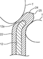
- the cleaning unit 20 may include a group of brush hairs including a plurality of brush hairs 27.
- Each brush hair 27 is integrally formed of the same material as the cleaning unit main body 22, protrudes outward in the axis-perpendicular direction from the outer peripheral surface of the cleaning unit main body 22, and is separated from the outer peripheral surface of the cleaning unit main body 22. It is preferable to have a shape that gradually reduces the outer shape of the bristles 27 as it goes on. Further, the brush bristles 27 fall when the bristles 27 come into contact with the object to be cleaned T when being inserted into the gap S.
- the brush bristle group may include first curved brush bristles 27a and second curved brush bristles 27b.
- the first curved bristle 27a has a shape that gradually curves from the base end part 12b side toward the insertion end part 12a side toward the outside from the cleaning part main body 22 in the axis orthogonal direction.
- the second curved brush bristles 27b have a shape that gradually curves from the insertion end portion 12a side toward the base end portion 12b side toward the outside from the cleaning portion main body 22 in the axis orthogonal direction.
- or the to-be-cleaned object T can be effectively cleaned both when the cleaning part 20 is inserted in the said clearance gap S, and at the time of extraction from the said clearance gap S.
- the bristle group includes both the first curved brush bristles 27a and the second curved brush bristles 27b
- the first curved brush bristles 27a effectively use the gap S or the object to be cleaned T during the insertion.
- the second curved brush bristles 27b effectively clean the gap S or the object to be cleaned T during the extraction.
- the brush bristle group includes both the first curved brush bristle 27a and the second curved brush bristle 27b
- the brush bristle group includes only one of the first curved brush bristle 27a and the second curved brush bristle 27b.
- the cleaning tool of this embodiment is a cleaning tool for cleaning a minute gap formed between adjacent objects to be cleaned, and has a shape that extends in a specific direction and can be inserted into the gap.
- a shaft portion having an insertion end portion formed at one end in the specific direction and a base end portion formed at the other end in the specific direction, and an elastomer having a hardness lower than the hardness of the shaft portion.
- the insertion end portion has a shape that can be flexibly deformed to allow displacement in an axis orthogonal direction orthogonal to the axial direction of the shaft portion with respect to the base end portion
- the cleaning portion includes the shaft portion
- the cleaning unit body that covers the outer peripheral surface and the insertion end And a guide portion that protrudes outward in the axial direction and guides insertion of the cleaning portion main body into the gap, and the guide portion has a protruding dimension from the insertion end portion of the guide portion. It has a shape that is equal to or greater than the thickness of the cleaning unit main body and is elastically deformable so as to be displaced in the direction perpendicular to the axis with respect to the insertion end.
- the guide unit positioned at the tip in the insertion direction of the cleaning unit contacts the object to be cleaned.
- the guide portion is elastically deformed so as to be displaced in the direction perpendicular to the axis toward the back of the gap with respect to the insertion end portion, and the shaft portion is The insertion end portion of the portion is bent and deformed so as to be displaced in the same direction as the displacement direction of the guide portion with respect to the base end portion of the shaft portion.
- this cleaning tool inserts the shaft portion in the posture as it is after the guide portion contacts the object to be cleaned, so that the cleaning portion is moved to the back of the gap while being accompanied by elastic deformation of the guide portion and bending deformation of the shaft portion. Inserted. That is, in this cleaning tool, when the cleaning unit is inserted into the gap, the cleaning unit body is guided to be inserted into the gap by the guide unit having a relatively low hardness, and further cleaning unit is inserted after the guide. In the interior, the gap or the object to be cleaned is effectively cleaned by the cleaning unit body that covers the outer peripheral surface of the shaft portion having relatively high hardness. Therefore, with this cleaning tool, it becomes easy to clean minute gaps such as between keys on the keyboard or between teeth.
- the protruding dimension of the guide portion is set to be not less than 3 times and not more than 10 times the thickness of the cleaning portion main body.
- the protruding dimension of the guide part (the axial dimension) to be three times or more the thickness of the cleaning part body, the amount of displacement of the guide part when the guide part is elastically deformed is sufficient. Therefore, the guide portion is effectively guided toward the back of the gap as the shaft portion is inserted after the guide portion contacts the object to be cleaned.
- the projecting dimension of the guide part to be 10 times or less the thickness of the cleaning part main body, the strength of the guide part decreases due to the projecting dimension of the guide part becoming too long, that is, And the fall of the insertability to the clearance gap between guide parts is suppressed.
- the protrusion dimension of the guide portion is set to be 0.6 times or more and 4 times or less the dimension of the insertion end portion in the axis-orthogonal direction, and 0.7 times or more and 2 times. More preferably, it is set to be twice or less.
- the guide part when the protruding dimension of the guide part is set to 0.6 or more times the dimension of the insertion end part in the direction perpendicular to the axis, the guide part with respect to the dimension in the direction perpendicular to the axis of the insertion end part is elastically deformed. Since the ratio of the amount of displacement of the guide part is sufficiently large, the guide part is effectively guided toward the back of the gap as the shaft part is inserted after the guide part contacts the object to be cleaned. On the other hand, by setting the projecting dimension of the guide part to be four times or less the dimension of the insertion end part in the axis-perpendicular direction, the guide part has a relatively long projecting dimension. A decrease, that is, a decrease in insertability into the gap of the guide portion is suppressed.
- the protrusion dimension of the said guide part is set to 0.10 mm or more and 1.2 mm or less, and the dimension of the said axial direction of the said shaft part is set to 10 mm or more,
- the said cleaning In a state in which a portion of the tool that is 10 mm away from the distal end of the guide portion toward the proximal end portion is fixed, the guide portion is moved in the axial direction with elastic deformation of the guide portion and bending deformation of the shaft portion.
- the elastomer shore is adjusted so that a pressing force required to press the guide portion from the insertion end portion side toward the base end portion side is 5.0 N or less and 8.0 N or less until the displacement is 5.0 mm. It is preferable that the hardness is set.
- the pressing force includes a force necessary to elastically deform the guide portion made of the elastomer in addition to a force necessary to bend and deform the shaft portion.
- the deformation failure (the guide property to the back of the clearance of the cleaning unit main body by the guide unit is impaired) is suppressed.
- the cleaning unit further includes a minute protrusion provided at a tip of the guide unit and having an outer shape smaller than the outer shape of the guide unit.
- the microprotrusion guides the displacement direction of the guide portion so that the guide portion is elastically deformed toward the back of the gap. Insertion into the gap is further facilitated.
- the cleaning unit further includes a brush bristle group including a plurality of brush hairs each having a shape projecting outward in the axis-orthogonal direction from the outer peripheral surface of the cleaning unit body,
- the brush bristle group has a first curved brush bristle that has a shape that gradually curves from the base end side toward the insertion end side as it goes outward from the cleaning unit main body in the direction orthogonal to the axis, and the shaft It is preferable to include second curved brush bristles having a shape that gradually curves from the insertion end side toward the base end side as it goes outward from the cleaning unit main body in the orthogonal direction.
- the bristle group includes first curved brush hairs having a shape that gradually curves from the proximal end side toward the insertion end side as it goes outward from the cleaning unit body, and outward from the cleaning unit body.
- the second curved brush bristles having a shape that gradually curves from the insertion end side toward the base end side as it goes toward the first end. The second curved brush bristles effectively clean the gap or the object to be cleaned during the extraction.
- the brush bristle group includes the first curved brush bristle and the second curved brush bristle, so that cleaning is performed as compared with the case where the brush bristle group includes only one of the first curved brush bristle and the second curved brush bristle.
- the insertion resistance felt by the operator when inserting the part into the gap and the pulling resistance felt by the operator when pulling the cleaning part out of the gap become substantially uniform. For this reason, the cleaning operation by the operator becomes easy.
- the first curved bristle and the second curved bristle are designed such that brush bristle having a shape extending linearly outward from the outer peripheral surface of the cleaning unit main body in the direction perpendicular to the axis is formed.
- Brush hair molded by a mold, and gradually from the base end side to the insertion end side or from the insertion end side to the base end as it goes outward from the cleaning unit body after releasing from the mold Including those that have a shape that curves toward the part side.
- the insertion end portion and the guide portion are each formed in a hemispherical shape that curves so as to protrude outward in the axial direction, and the radius of the guide portion. Is preferably set to 1.1 times to 8 times the radius of the insertion end, more preferably 1.1 times to 4 times, and more preferably 1.2 times to 2 times. More preferably, it is set to less than twice.
- the guide part guides the cleaning part body to the gap when the cleaning part is inserted into the gap. Increases effectiveness.
Landscapes
- Chemical & Material Sciences (AREA)
- Engineering & Computer Science (AREA)
- Materials Engineering (AREA)
- Cleaning In General (AREA)
Abstract
清掃具であって、挿入端部(12a)及び基端部を有する軸部(12)と、エラストマーからなり隙間を清掃可能な清掃部と、を備える。軸部(12)は、挿入端部(12a)が基端部に対して軸直交方向に変位するのを許容するように撓み変形可能な形状を有する。清掃部は、清掃部本体(22)と、挿入端部(12a)よりも軸方向の外向きに突出するとともに清掃部本体(22)の隙間への挿入を案内する案内部(24)と、を有する。案内部(24)は、当該案内部(24)の挿入端部(12a)からの突出寸法(t2)が清掃部本体(22)の厚さ(t1)以上であり、かつ、挿入端部(12a)に対して軸直交方向に変位するように弾性変形可能な形状を有する。
Description
本発明は、清掃具に関する。
従来、キーボードのキー間のような微小な隙間を清掃するための清掃具が知られている。例えば、特許文献1には、軸部と、この軸部の先端部に取り付けられた繊維塊(清掃部)と、を備える清掃具が開示されている。清掃部は、所定量の繊維を圧縮することにより形成されている。
特許文献1に記載される清掃具では、繊維からなる清掃部の表面の毛羽立ちに起因して、互いに隣接する被清掃物間(キーボードのキー間等)に形成される微小な隙間への清掃部の挿入が困難となることがある。具体的に、前記微小な隙間の清掃中に、清掃部が被清掃物への衝突を繰り返すことによって当該清掃部の表面が毛羽立ち、これにより微小な隙間への清掃部の挿入が困難となる場合がある。
一方、毛羽立ちの問題を生じさせず、微小な隙間を清掃するための清掃部の成形に用いられることが可能な材料として、エラストマーが知られている。このエラストマーにより形成された清掃部は、毛羽立ちを生じさせず、当該清掃部と被清掃物との間に生じる摩擦により前記微小な隙間の汚れを有効に除去する。
しかしながら、エラストマーにより清掃部を形成した場合であっても、前記微小な隙間への清掃部の挿入性の改善は不十分である。具体的に、微小な隙間への清掃部の挿入時に当該清掃部の先端が被清掃物に接触すると、それよりも隙間の奥に向かって清掃部を挿入するには、清掃部の隙間の奥への挿入が許容されるように清掃部の前記隙間に対する挿入方向(軸部の姿勢)を変える操作が必要となる。この操作は、清掃部の先端が被清掃物に接触するたびに必要となるため、清掃部を隙間の奥まで挿入することが非常に困難である。この課題は、狭い空間での軸部の操作等、軸部の姿勢の調整範囲に制限がある場合に特に顕著になる。
本発明の目的は、容易に微小な隙間の奥まで清掃部を挿入させることが可能な清掃具を提供することである。
本発明の一局面に従う清掃具は、互いに隣接する被清掃物間に形成される微小な隙間を清掃するための清掃具であって、特定方向に延びるとともに前記隙間に挿通されることが可能な形状を有し、かつ、前記特定方向の一端に形成された挿入端部及び前記特定方向の他端に形成された基端部を有する軸部と、前記軸部の硬度よりも低い硬度を有するエラストマーからなり、前記挿入端部を含みかつ前記軸部のうち当該軸部の軸方向の寸法以下の寸法を有する部位を被覆するとともに前記隙間を清掃可能な清掃部と、を備え、前記軸部は、前記挿入端部が前記基端部に対して当該軸部の軸方向と直交する軸直交方向に変位するのを許容するように撓み変形可能な形状を有し、前記清掃部は、前記軸部の外周面を被覆する清掃部本体と、前記挿入端部よりも前記軸方向の外向きに突出するとともに前記清掃部本体の前記隙間への挿入を案内する案内部と、を有し、前記案内部は、当該案内部の前記挿入端部からの突出寸法が前記清掃部本体の厚さ以上であり、かつ、前記挿入端部に対して前記軸直交方向に変位するように弾性変形可能な形状を有する。
本発明の一実施形態の清掃具1について、図1~図5を参照しながら説明する。
本清掃具1は、互いに隣接する被清掃物T(図4及び図5を参照)間に形成される微小な隙間(キーボードのキー間や奥歯同士の隙間等)を清掃するためのものである。図1に示されるように、本実施形態の清掃具1は、基部10と、基部10の硬度よりも低い硬度を有するエラストマーからなる清掃部20と、を備えている。基部10は、ポリプロピレン等の合成樹脂により形成される。当該基部10は、基部10に適度な弾性が得られ、隙間への挿入性が高まるという観点から、ポリプロピレンにより形成されることが好ましいが、ABS、ポリカーボネート、ポリブチレンテレフタレート、ポリエチレンテレフタレート、ポリスチレン、ポリアセタール等の合成樹脂により形成されていてもよい。前記エラストマーとして、スチレン系エラストマーが用いられることが好ましい。ただし、前記エラストマーとして、シリコン、オレフィン系エラストマー、ポリエステル系エラストマー等が用いられてもよい。
基部10は、特定方向(図1の上下方向)に沿って直線状に延びる形状を有する軸部12と、把持部14と、を有する。
軸部12は、微小な隙間S(図4を参照)へ挿入されることが可能な形状を有する。軸部12は、前記特定方向の一端に形成された挿入端部12aと、前記特定方向の他端に形成された基端部12bと、を有する。軸部12は、挿入端部12aが基端部12bを支点として軸部12の軸方向と直交する軸直交方向(図1の左右方向)に変位するように撓み変形可能な形状を有する。本実施形態では、軸部12は、略円柱状に形成されている。詳細には、軸部12は、基端部12bから挿入端部12aに向かうにしたがって次第にかつわずかに当該軸部12の外径を小さくする形状を有する。挿入端部12aは、軸方向の外向きに凸となるように湾曲する半球状に形成されている。本実施形態では、軸部12の軸方向の寸法は、29mmに設定されており、基端部12bの直径は、1.2mmに設定されている。また、挿入端部12aの半径は、0.27mmに設定されている。
把持部14は、人により把持される部位である。把持部14は、軸部12の基端部12bに接続されている。本実施形態では、把持部14は、軸部12の外径よりも一回り大きな外径を有する円柱状に形成されている。ただし、把持部14の形状は、これに限られない。
清掃部20は、挿入端部12aを含みかつ軸部12のうち当該軸部12の前記軸方向の寸法以下の寸法を有する部位を被覆するとともに隙間Sを清掃可能な形状を有する。具体的に、清掃部20は、軸部12のうち、挿入端部12aから基端部12bに向かう方向に沿って挿入端部12aから連続的に延びる部位を被覆する形状を有する。本実施形態では、清掃部20の前記軸方向の寸法は、15.4mmに設定されている。清掃部20は、清掃部本体22と、案内部24と、を有する。
清掃部本体22は、挿入端部12aを含む軸部12の外周面を被覆する形状を有する。清掃部本体22は、円筒状の外周面を有している。図2に示されるように、清掃部本体22は、軸部12のうち挿入端部12a以外の部位の外周面を被覆する第1被覆部22aと、挿入端部12aの外周面を被覆する第2被覆部22bと、を有する。第1被覆部22aの厚さ(図2の左右方向の寸法)t1は、0.10mmに設定されている。第2被覆部22bは、第1被覆部22aから軸方向の外向きに離間するにしたがって次第にその厚さ増大させる形状を有する。
案内部24は、挿入端部12aよりも軸方向の外向きに突出するとともに清掃部本体22の隙間Sへの挿入を案内する形状を有する。案内部24は、挿入端部12aに対して前記軸直交方向に弾性変形可能な形状を有する。図2に示されるように、案内部24の挿入端部12aからの突出寸法t2は、第1被覆部22aの厚さt1よりも大きく設定されている。この突出寸法t2は、第1被覆部22aの厚さt1の3倍以上10倍以下に設定されることが好ましい。より好ましくは、前記突出寸法t2は、第1被覆部22aの厚さt1の3倍以上5倍以下に設定される。さらに、前記突出寸法t2は、挿入端部12aの直径dの0.6倍以上4倍以下(挿入端部12aの半径の1.1倍以上8倍以下)に設定されることが好ましい。本実施形態では、前記突出寸法t2は、第1被覆部22aの厚さt1の4倍、すなわち、0.40mmに設定されている。なお、この値は、挿入端部12aの半径の約1.5倍である。
案内部24のうち挿入端部12aと接する部位における前記軸方向と直交する面での断面は、第2被覆部22bの先端部の半径と同じ半径を有する円形に形成されている。本実施形態では、案内部24は、前記軸方向の外向きに凸となるように湾曲する半球状に形成されている。すなわち、前記突出寸法t2は、案内部24の半径に等しい値に設定されている。
本実施形態では、図2に示されるように、案内部24の先端に微小突起25が接続されている。微小突起25は、案内部24の先端から軸方向の外向きに突出する形状を有する。本実施形態では、微小突起25は、円錐状に形成されている。具体的に、微小突起25と案内部24との接続部の外径は、案内部24と第2被覆部22bとの接続部の外径(案内部24の半径)よりも小さく設定されており、微小突起25の軸方向の寸法は、案内部24の突出寸法t2よりも小さく設定されている。なお、この微小突起25は、省略されてもよい。
本実施形態では、清掃具1のうち案内部24の先端から前記基端部側に10mm離間した部位を固定した状態において、案内部24の弾性変形と軸部12の撓み変形とを伴いながら案内部24が前記軸方向に5.0mm変位するまで当該案内部24を挿入端部12a側から基端部12b側に向かって押圧するのに必要な押圧力が1.0N以上8.0N以下となるように、前記エラストマーのショア硬さが設定されている。より好ましくは、前記押圧力が3.0N以上7.0N以下となるように、更に好ましくは、前記押圧力が4.0N以上7.0N以下となるように、前記エラストマーのショア硬さが設定される。前記エラストマーとして、A0~A50のショア硬さを有するものを用いることができ、本実施形態では、A40のショア硬さを有するものが用いられる。
前記押圧力は、図3に示される押圧試験機30により測定される。押圧試験機30は、清掃具1を固定可能な固定台32と、固定台32に固定されている清掃具1を押圧可能な押圧部34と、を有する。押圧部34は、固定台32の鉛直上方に配置されており、固定台32に固定されている清掃具1を鉛直下向きに押圧可能に構成されている。
次に、押圧試験機30を用いて前記押圧力を測定する方法について説明する。
まず、把持部14から案内部24に向かう向きが鉛直上向きとなる姿勢で清掃具1を固定台32に固定する。具体的に、図3に示されるように、清掃具1のうち案内部24の先端から基端部12b側に10mm以上離間する部位全体を固定台32により固定する。
次に、押圧部34により清掃具1を鉛直下向きに押圧する。具体的に、押圧部34の下面が案内部24に接触した状態から当該押圧部34を固定台32に向かって鉛直下向きに5.0mm変位させる。この押圧部34の押圧に伴い、案内部24は、当該案内部24の弾性変形と軸部12の撓み変形とを伴いながら軸方向に5.0mm変位する。そして、押圧部34が5.0mm変位したときの押圧力が測定される。
以上に説明した本清掃具1の使用方法を、図4及び図5を参照しながら説明する。なお、図4及び図5では、清掃具1の先端近傍の断面が示されている。
まず、清掃部20の先端に位置する案内部24を先頭にして被清掃物T同士の隙間Sに向けて本清掃具1を挿入する。そして、案内部24が被清掃物Tに接触した後、そのまま軸部12を前記挿入方向に沿って挿入する。そうすると、図5に示されるように、軸部12の前記挿入方向に沿った挿入に伴って、案内部24は、挿入端部12aに対して隙間Sの奥へ向かって軸直交方向に変位するように弾性変形し、かつ、軸部12は、挿入端部12aが基端部12bに対して案内部24の変位方向と同方向に変位するように撓み変形する。このため、軸部12をそのままの姿勢で前記挿入方向に沿ってさらに挿入することにより、清掃部20が隙間Sの奥まで挿入される。
このように、本清掃具1では、清掃部20の隙間Sへの挿入時には、相対的に低い硬度を有する案内部24によって清掃部本体22が隙間Sへ挿入されるように案内され、その案内後におけるさらなる清掃部20の挿入中には、相対的に高い硬度を有する軸部12の外周面を被覆する清掃部本体22によって隙間Sないし被清掃物Tが有効に清掃される。
以上のように、本清掃具1は、案内部24の被清掃物Tへの接触後に軸部12をそのままの姿勢で挿入することによって、案内部24の弾性変形及び軸部12の撓み変形を伴いながら清掃部20が隙間Sの奥まで挿入される。このため、本清掃具1では、清掃部20の先端が被清掃物Tに接触した際に、清掃部20の隙間Sへの挿入方向を調整する操作、すなわち、清掃部20の長手方向が前記隙間Sの延びる方向と一致するように軸部12の姿勢を調整する操作が不要となる。このことは、互いに隣接する奥歯同士の隙間Sへ清掃部20を挿入する場合、すなわち、被清掃物Tが奥歯である場合に特に有効である。具体的に、奥歯は、口腔内のうち比較的奥の狭い空間内に位置しているため、この空間内で清掃部20の長手方向が前記隙間Sの延びる方向と一致するように軸部12の姿勢を調整する操作は、唇によって制限される。よって、本清掃具1は、奥歯同士の隙間Sの清掃に特に有効となる。
また、本実施形態では、案内部24の突出寸法t2は、第1被覆部22aの厚さt1の4倍に設定されているので、前記隙間Sへの清掃部20の挿入がさらに容易になる。具体的に、案内部24の突出寸法t2が第1被覆部22aの厚さt1の3倍以上に設定されることにより、案内部24が弾性変形したときの当該案内部24の変位量が十分に確保されるので、案内部24の被清掃物Tへの接触後の軸部12の挿入に伴って当該案内部24が隙間Sの奥へ向かって有効に誘導される。一方、案内部24の突出寸法t2が第1被覆部22aの厚さt1の10倍以下に設定されることにより、案内部24の突出寸法t2が相対的に長くなり過ぎることに起因する当該案内部24の強度の低下、すなわち、案内部24の隙間Sへの挿入性の低下が抑制される。
さらに、本実施形態では、前記突出寸法t2は、挿入端部12aの直径dの0.6倍以上4倍以下の範囲に設定されているので、前記隙間Sへの清掃部20の挿入が一層容易になる。具体的に、案内部24の突出寸法t2が挿入端部12aの直径dの0.6倍以上に設定されることにより、挿入端部12aの直径dに対する案内部24が弾性変形したときの当該案内部24の変位量の割合が十分大きく確保されるので、案内部24の被清掃物Tへの接触後の軸部12の挿入に伴って当該案内部24が隙間Sの奥へ向かって有効に誘導される。一方、案内部24の突出寸法t2が挿入端部12aの直径dの4倍以下に設定されることにより、案内部24の突出寸法t2が相対的に長くなり過ぎることに起因する当該案内部24の強度の低下、すなわち、案内部24の隙間Sへの挿入性の低下が抑制される。
また、本実施形態では、前記押圧力(清掃具1のうち案内部24の先端から基端部12b側に10mm離間した部位を固定した状態において、案内部24の弾性変形と軸部12の撓み変形とを伴いながら案内部24が前記軸方向に5.0mm変位するまで当該案内部24を挿入端部12a側から基端部12b側に向かって押圧するのに必要な力)が1.0N以上8.0N以下となるように、前記エラストマーとして、A40のショア硬さを有するものが用いられている。このため、案内部24が被清掃物Tに接触した状態からさらに軸部12が挿入されたときに清掃部20が前記隙間Sにより一層に挿入されやすくなる。具体的に、前記押圧力には、軸部12を撓み変形させるのに必要な力に加え、前記エラストマーからなる案内部24を弾性変形させるのに必要な力が含まれるため、この押圧力が1.0N以上となるように前記エラストマーのショア硬さが設定されることにより、案内部24の強度が十分に確保され、これにより、案内部24が被清掃物Tに接触した状態からさらに軸部12が挿入されたときに当該案内部24が前記隙間Sの奥に向かって有効に弾性変形する。一方、前記押圧力が8.0N以下となるように前記エラストマーのショア硬さが設定されることにより、案内部24が被清掃物Tに接触した状態からさらに軸部12が挿入されたときの当該案内部24の変形不良(案内部24による清掃部本体22の隙間Sの奥への案内性が損なわれること)が抑制される。
また、案内部24の先端に設けられた微小突起25は、清掃部20の前記隙間Sへの挿入性を向上させる。具体的に、微小突起25が被清掃物Tに接触した際、当該微小突起25は、案内部24が隙間Sの奥へ向かって弾性変形するように当該案内部24の変位方向を誘導するので、清掃部20の前記隙間Sへの挿入がさらに容易になる。
なお、今回開示された上記実施形態は、すべての点で例示であって制限的なものではないと考えられるべきである。本発明の範囲は、上記した実施形態の説明ではなく特許請求の範囲によって示され、さらに特許請求の範囲と均等の意味および範囲内でのすべての変更が含まれる。
挿入端部12aの形状は、上記実施形態の例、すなわち、半球状に限られない。挿入端部12aは、円柱状や円錐台状、あるいは、多角柱状に形成されてもよい。また、軸部12のうち挿入端部12a以外の部位は、多角柱状に形成されてもよい。
また、図6に示されるように、清掃部20は、複数のブラシ毛27からなるブラシ毛群を有していてもよい。各ブラシ毛27は、清掃部本体22と同一素材で一体的に形成され、当該清掃部本体22の外周面から前記軸直交方向の外向きに突出するとともに、清掃部本体22の外周面から離間するにしたがって次第に当該ブラシ毛27の外形を小さくする形状を有することが好ましい。また、ブラシ毛27は、隙間Sへの挿入時に、ブラシ毛27が被清掃物Tに接触することで倒れる。この際、隙間Sへの挿入性が高まるという観点から、倒れたブラシ毛27は、隣り合うブラシ毛27と殆ど重ならない又は全く重ならないことが好ましい。また、ブラシ毛群は、第1湾曲ブラシ毛27aと、第2湾曲ブラシ毛27bと、を含んでもよい。第1湾曲ブラシ毛27aは、前記軸直交方向について清掃部本体22から外側に向かうにしたがって次第に基端部12b側から挿入端部12a側に向かうように湾曲する形状を有する。第2湾曲ブラシ毛27bは、前記軸直交方向について清掃部本体22から外側に向かうにしたがって次第に挿入端部12a側から基端部12b側に向かうように湾曲する形状を有する形状を有する。このようにすれば、清掃部20の前記隙間Sへの挿入時と前記隙間Sからの抜取時との双方において効果的に前記隙間Sないし被清掃物Tを清掃することができる。具体的に、ブラシ毛群は、第1湾曲ブラシ毛27aと第2湾曲ブラシ毛27bとの双方を含むので、前記挿入時には第1湾曲ブラシ毛27aが前記隙間Sないし被清掃物Tを有効に清掃する一方、前記抜取時には第2湾曲ブラシ毛27bが前記隙間Sないし被清掃物Tを有効に清掃する。
さらに、ブラシ毛群が第1湾曲ブラシ毛27a及び第2湾曲ブラシ毛27bの双方を含むことにより、ブラシ毛群が第1湾曲ブラシ毛27a及び第2湾曲ブラシ毛27bのいずれか一方のみを含む場合に比べ、清掃部20を前記隙間Sへ挿入させるときに操作者が感じる挿入抵抗と清掃部20を前記隙間Sから引き抜くときに操作者が感じる引抜抵抗とが略均一になる。このため、操作者による清掃操作が容易になる。
ここで、上記実施形態について概説する。
本実施形態の清掃具は、互いに隣接する被清掃物間に形成される微小な隙間を清掃するための清掃具であって、特定方向に延びるとともに前記隙間に挿通されることが可能な形状を有し、かつ、前記特定方向の一端に形成された挿入端部及び前記特定方向の他端に形成された基端部を有する軸部と、前記軸部の硬度よりも低い硬度を有するエラストマーからなり、前記挿入端部を含みかつ前記軸部のうち当該軸部の軸方向の寸法以下の寸法を有する部位を被覆するとともに前記隙間を清掃可能な清掃部と、を備え、前記軸部は、前記挿入端部が前記基端部に対して当該軸部の軸方向と直交する軸直交方向に変位するのを許容するように撓み変形可能な形状を有し、前記清掃部は、前記軸部の外周面を被覆する清掃部本体と、前記挿入端部よりも前記軸方向の外向きに突出するとともに前記清掃部本体の前記隙間への挿入を案内する案内部と、を有し、前記案内部は、当該案内部の前記挿入端部からの突出寸法が前記清掃部本体の厚さ以上であり、かつ、前記挿入端部に対して前記軸直交方向に変位するように弾性変形可能な形状を有する。
本清掃具では、互いに隣接する被清掃物間に形成される微小な隙間への清掃部の挿入時において当該清掃部の挿入方向の先端に位置する案内部が被清掃物に接触した後、清掃部の前記挿入方向に沿った挿入に伴って、案内部は、挿入端部に対して前記隙間の奥へ向かって軸直交方向に変位するように弾性変形し、かつ、軸部は、当該軸部の挿入端部が当該軸部の基端部に対して前記案内部の変位方向と同方向に変位するように撓み変形する。よって、本清掃具は、案内部の被清掃物への接触後に軸部をそのままの姿勢で挿入することによって、案内部の弾性変形及び軸部の撓み変形を伴いながら清掃部が隙間の奥まで挿入される。つまり、本清掃具では、清掃部の前記隙間への挿入時には、相対的に低い硬度を有する案内部によって清掃部本体が隙間へ挿入されるように案内され、その案内後におけるさらなる清掃部の挿入中には、相対的に高い硬度を有する軸部の外周面を被覆する清掃部本体によって前記隙間ないし被清掃物が有効に清掃される。したがって、本清掃具では、キーボードのキー間や歯間のような微小な隙間の清掃が容易になる。
この場合において、前記案内部の突出寸法は、前記清掃部本体の厚さの3倍以上10倍以下に設定されていることが好ましい。
このようにすれば、微小な隙間への清掃部の挿入がさらに容易になる。具体的に、案内部の突出寸法(前記軸方向の寸法)が清掃部本体の厚さの3倍以上に設定されることにより、案内部が弾性変形したときの当該案内部の変位量が十分に確保されるので、案内部の被清掃物への接触後の軸部の挿入に伴って当該案内部が隙間の奥へ向かって有効に誘導される。一方、案内部の突出寸法が清掃部本体の厚さの10倍以下に設定されることにより、案内部の突出寸法が相対的に長くなり過ぎることに起因する当該案内部の強度の低下、すなわち、案内部の隙間への挿入性の低下が抑制される。
また、本清掃具において、前記案内部の突出寸法は、前記挿入端部の前記軸直交方向の寸法の0.6倍以上4倍以下に設定されていることが好ましく、0.7倍以上2倍以下に設定されることがより好ましい。
このようにすれば、微小な隙間への清掃部の挿入が一層容易になる。具体的に、案内部の突出寸法が挿入端部の軸直交方向の寸法の0.6倍以上に設定されることにより、挿入端部の軸直交方向の寸法に対する案内部が弾性変形したときの当該案内部の変位量の割合が十分大きく確保されるので、案内部の被清掃物への接触後の軸部の挿入に伴って当該案内部が隙間の奥へ向かって有効に誘導される。一方、案内部の突出寸法が挿入端部の軸直交方向の寸法の4倍以下に設定されることにより、案内部の突出寸法が相対的に長くなり過ぎることに起因する当該案内部の強度の低下、すなわち、案内部の隙間への挿入性の低下が抑制される。
また、本清掃具において、前記案内部の突出寸法は、0.10mm以上1.2mm以下に設定されており、前記軸部の前記軸方向の寸法は、10mm以上に設定されており、当該清掃具のうち前記案内部の先端から前記基端部側に10mm離間した部位を固定した状態において、前記案内部の弾性変形と前記軸部の撓み変形とを伴いながら前記案内部が前記軸方向に5.0mm変位するまで当該案内部を前記挿入端部側から前記基端部側に向かって押圧するのに必要な押圧力が1.0N以上8.0N以下となるように、前記エラストマーのショア硬さが設定されていることが好ましい。
前記押圧力が1.0N以上8.0N以下となるように前記エラストマーのショア硬さが設定されることにより、案内部が被清掃物に接触した状態からさらに軸部が挿入されたときに清掃部が前記隙間にさらに挿入されやすくなる。具体的に、前記押圧力には、軸部を撓み変形させるのに必要な力に加え、前記エラストマーからなる案内部を弾性変形させるのに必要な力が含まれるため、この押圧力が1.0N以上となるように前記エラストマーのショア硬さが設定されることにより、案内部の強度が十分に確保され、これにより、案内部が被清掃物に接触した状態からさらに軸部が挿入されたときに当該案内部が前記隙間の奥に向かって有効に弾性変形する。一方、前記押圧力が8.0N以下となるように前記エラストマーのショア硬さが設定されることにより、案内部が被清掃物に接触した状態からさらに軸部が挿入されたときの当該案内部の変形不良(案内部による清掃部本体の隙間の奥への案内性が損なわれること)が抑制される。
また、本清掃具において、前記清掃部は、前記案内部の先端に設けられており当該案内部の外形よりも小さな外形を有する微小突起をさらに有することが好ましい。
このようにすれば、微小突起が被清掃物に接触した際、当該微小突起は、案内部が隙間の奥へ向かって弾性変形するように当該案内部の変位方向を誘導するので、清掃部の前記隙間への挿入がさらに容易になる。
また、本清掃具において、前記清掃部は、それぞれが前記清掃部本体の外周面から前記軸直交方向の外向きに突出する形状を有する複数のブラシ毛からなるブラシ毛群をさらに有し、前記ブラシ毛群は、前記軸直交方向について前記清掃部本体から外側に向かうにしたがって次第に前記基端部側から前記挿入端部側に向かうように湾曲する形状を有する第1湾曲ブラシ毛と、前記軸直交方向について前記清掃部本体から外側に向かうにしたがって次第に前記挿入端部側から前記基端部側に向かうように湾曲する形状を有する第2湾曲ブラシ毛と、を含むことが好ましい。
このようにすれば、清掃部の隙間への挿入時と前記隙間からの抜取時との双方において効果的に前記隙間ないし被清掃物を清掃することができる。具体的に、ブラシ毛群は、清掃部本体から外側に向かうにしたがって次第に基端部側から挿入端部側に向かうように湾曲する形状を有する第1湾曲ブラシ毛と、清掃部本体から外側に向かうにしたがって次第に挿入端部側から基端部側に向かうように湾曲する形状を有する第2湾曲ブラシ毛と、の双方を含むので、前記挿入時には第1湾曲ブラシ毛が前記隙間ないし被清掃物を有効に清掃する一方、前記抜取時には第2湾曲ブラシ毛が前記隙間ないし被清掃物を有効に清掃する。
さらに、ブラシ毛群が第1湾曲ブラシ毛と第2湾曲ブラシ毛とを含むことにより、ブラシ毛群が第1湾曲ブラシ毛及び第2湾曲ブラシ毛のいずれか一方のみを含む場合に比べ、清掃部を前記隙間へ挿入させるときに操作者が感じる挿入抵抗と清掃部を前記隙間から引き抜くときに操作者が感じる引抜抵抗とが略均一になる。このため、操作者による清掃操作が容易になる。
なお、前記第1湾曲ブラシ毛及び前記第2湾曲ブラシ毛は、清掃部本体の外周面から前記軸直交方向の外向きに直線状に延びる形状を有するブラシ毛が形成されるように設計された金型により成形されたブラシ毛であって、前記金型からの離型後に清掃部本体から外側に向かうにしたがって次第に基端部側から挿入端部側に、あるいは、挿入端部側から基端部側に向かうように湾曲する形状となったものを含む。
また、本清掃具において、前記挿入端部及び前記案内部は、それぞれ前記軸方向の外向きに凸となるように湾曲する半球状に形成されていることが好ましく、また、前記案内部の半径は、前記挿入端部の半径の1.1倍以上8倍以下に設定されていることが好ましく、1.1倍以上4倍以下に設定されていることがより好ましく、1.2倍以上2倍以下に設定されていることが更に好ましい。
このようにすれば、前記案内部が略三角錐状や、円錐台状に形成されている場合に比べて、清掃部を前記隙間に挿入する際における案内部による清掃部本体の隙間への案内効果が高まる。
Claims (7)
- 互いに隣接する被清掃物間に形成される微小な隙間を清掃するための清掃具であって、
特定方向に延びるとともに前記隙間に挿通されることが可能な形状を有し、かつ、前記特定方向の一端に形成された挿入端部及び前記特定方向の他端に形成された基端部を有する軸部と、
前記軸部の硬度よりも低い硬度を有するエラストマーからなり、前記挿入端部を含みかつ前記軸部のうち当該軸部の軸方向の寸法以下の寸法を有する部位を被覆するとともに前記隙間を清掃可能な清掃部と、を備え、
前記軸部は、前記挿入端部が前記基端部に対して当該軸部の軸方向と直交する軸直交方向に変位するのを許容するように撓み変形可能な形状を有し、
前記清掃部は、前記軸部の外周面を被覆する清掃部本体と、前記挿入端部よりも前記軸方向の外向きに突出するとともに前記清掃部本体の前記隙間への挿入を案内する案内部と、を有し、
前記案内部は、当該案内部の前記挿入端部からの突出寸法が前記清掃部本体の厚さ以上であり、かつ、前記挿入端部に対して前記軸直交方向に変位するように弾性変形可能な形状を有する、清掃具。 - 請求項1に記載の清掃具において、
前記案内部の突出寸法は、前記清掃部本体の厚さの3倍以上10倍以下に設定されている、清掃具。 - 請求項1又は2に記載の清掃具において、
前記案内部の突出寸法は、前記挿入端部の前記軸直交方向の寸法の0.6倍以上4倍以下に設定されている、清掃具。 - 請求項1ないし3のいずれかに記載の清掃具において、
前記案内部の突出寸法は、0.1mm以上1.2mm以下に設定されており、
前記軸部の前記軸方向の寸法は、10mm以上に設定されており、
当該清掃具のうち前記案内部の先端から前記基端部側に10mm離間した部位を固定した状態において、前記案内部の弾性変形と前記軸部の撓み変形とを伴いながら前記案内部が前記軸方向に5.0mm変位するまで当該案内部を前記挿入端部側から前記基端部側に向かって押圧するのに必要な押圧力が1.0N以上8.0N以下となるように、前記エラストマーのショア硬さが設定されている、清掃具。 - 請求項1ないし4のいずれかに記載の清掃具において、
前記清掃部は、前記案内部の先端に設けられており当該案内部の外形よりも小さな外形を有する微小突起をさらに有する、清掃具。 - 請求項1ないし5のいずれかに記載の清掃具において、
前記清掃部は、それぞれが前記清掃部本体の外周面から前記軸直交方向の外向きに突出する形状を有する複数のブラシ毛からなるブラシ毛群をさらに有し、
前記ブラシ毛群は、前記軸直交方向について前記清掃部本体から外側に向かうにしたがって次第に前記基端部側から前記挿入端部側に向かうように湾曲する形状を有する第1湾曲ブラシ毛と、前記軸直交方向について前記清掃部本体から外側に向かうにしたがって次第に前記挿入端部側から前記基端部側に向かうように湾曲する形状を有する第2湾曲ブラシ毛と、を含む、清掃具。 - 請求項1ないし6のいずれかに記載の清掃具において、
前記挿入端部及び前記案内部は、それぞれ前記軸方向の外向きに凸となるように湾曲する半球状に形成されており、
前記案内部の半径は、前記挿入端部の半径の1.1倍以上8倍以下に設定されている、清掃具。
Priority Applications (3)
| Application Number | Priority Date | Filing Date | Title |
|---|---|---|---|
| US15/542,494 US20180279766A1 (en) | 2015-01-16 | 2015-06-25 | Cleaning implement |
| CN201580073553.2A CN107107124B (zh) | 2015-01-16 | 2015-06-25 | 清洁具 |
| EP15877879.5A EP3246101B1 (en) | 2015-01-16 | 2015-06-25 | Cleaning implement |
Applications Claiming Priority (2)
| Application Number | Priority Date | Filing Date | Title |
|---|---|---|---|
| JP2015-006486 | 2015-01-16 | ||
| JP2015006486A JP6082038B2 (ja) | 2015-01-16 | 2015-01-16 | 清掃具 |
Publications (1)
| Publication Number | Publication Date |
|---|---|
| WO2016113927A1 true WO2016113927A1 (ja) | 2016-07-21 |
Family
ID=56405486
Family Applications (1)
| Application Number | Title | Priority Date | Filing Date |
|---|---|---|---|
| PCT/JP2015/068404 WO2016113927A1 (ja) | 2015-01-16 | 2015-06-25 | 清掃具 |
Country Status (5)
| Country | Link |
|---|---|
| US (1) | US20180279766A1 (ja) |
| EP (1) | EP3246101B1 (ja) |
| JP (1) | JP6082038B2 (ja) |
| CN (1) | CN107107124B (ja) |
| WO (1) | WO2016113927A1 (ja) |
Families Citing this family (1)
| Publication number | Priority date | Publication date | Assignee | Title |
|---|---|---|---|---|
| US10401971B2 (en) * | 2016-01-22 | 2019-09-03 | Philip J. Bruno | Keyboard cleaning system |
Citations (4)
| Publication number | Priority date | Publication date | Assignee | Title |
|---|---|---|---|---|
| US4085838A (en) * | 1974-03-14 | 1978-04-25 | Minnesota Mining And Manufacturing Company | Type correction article employing adhesives |
| JP2003220014A (ja) * | 2002-01-31 | 2003-08-05 | Itsushin Sangyo Kk | 掃除具 |
| JP2006000134A (ja) * | 2004-06-15 | 2006-01-05 | Atom Kosan Kk | 塵埃除去具 |
| JP2006263382A (ja) * | 2005-03-25 | 2006-10-05 | Glory Sangyo Kk | ハケ体 |
Family Cites Families (12)
| Publication number | Priority date | Publication date | Assignee | Title |
|---|---|---|---|---|
| US3724018A (en) * | 1971-08-04 | 1973-04-03 | A Sills | Swab with foam plastic wiping tip |
| US5283924A (en) * | 1990-09-21 | 1994-02-08 | Gillette Canada, Inc. | Interdental foam brush and treatment gel combination therewith |
| US5735012A (en) * | 1997-04-01 | 1998-04-07 | Chesebrough-Pond's Usa Co., Division Of Conopco, Inc. | Resiliently flexible toothbrush |
| GB9926418D0 (en) * | 1999-11-08 | 2000-01-12 | Westone Prod Ltd | Interdental brush |
| US6240592B1 (en) * | 1999-11-19 | 2001-06-05 | Bernard A. Li | Wheel detailing apparatus |
| CN102056508B (zh) * | 2008-06-13 | 2012-12-12 | 狮王株式会社 | 齿间刷的制造方法以及齿间刷 |
| US8559351B2 (en) * | 2008-08-01 | 2013-10-15 | Qualcomm Incorporated | Dedicated reference signal design for network MIMO |
| EP2857167B1 (en) * | 2012-05-24 | 2023-03-15 | Sunstar Suisse SA | Method for manufacturing an interdental cleaning tool and interdental cleaning tool |
| DE102012015663A1 (de) * | 2012-08-09 | 2014-05-15 | Interbros Gmbh | Interdental-Reiniger |
| DE102012015664A1 (de) * | 2012-08-09 | 2014-02-13 | Interbros Gmbh | Interdental-Reiniger |
| US20140166043A1 (en) * | 2012-12-14 | 2014-06-19 | Ranir, Llc | Interproximal cleaning tool and method of manufacture |
| WO2016076241A1 (ja) * | 2014-11-11 | 2016-05-19 | サンスター株式会社 | 歯間清掃具 |
-
2015
- 2015-01-16 JP JP2015006486A patent/JP6082038B2/ja active Active
- 2015-06-25 WO PCT/JP2015/068404 patent/WO2016113927A1/ja active Application Filing
- 2015-06-25 US US15/542,494 patent/US20180279766A1/en not_active Abandoned
- 2015-06-25 EP EP15877879.5A patent/EP3246101B1/en active Active
- 2015-06-25 CN CN201580073553.2A patent/CN107107124B/zh active Active
Patent Citations (4)
| Publication number | Priority date | Publication date | Assignee | Title |
|---|---|---|---|---|
| US4085838A (en) * | 1974-03-14 | 1978-04-25 | Minnesota Mining And Manufacturing Company | Type correction article employing adhesives |
| JP2003220014A (ja) * | 2002-01-31 | 2003-08-05 | Itsushin Sangyo Kk | 掃除具 |
| JP2006000134A (ja) * | 2004-06-15 | 2006-01-05 | Atom Kosan Kk | 塵埃除去具 |
| JP2006263382A (ja) * | 2005-03-25 | 2006-10-05 | Glory Sangyo Kk | ハケ体 |
Non-Patent Citations (1)
| Title |
|---|
| See also references of EP3246101A4 * |
Also Published As
| Publication number | Publication date |
|---|---|
| CN107107124A (zh) | 2017-08-29 |
| EP3246101B1 (en) | 2021-10-20 |
| EP3246101A1 (en) | 2017-11-22 |
| EP3246101A4 (en) | 2018-07-25 |
| JP6082038B2 (ja) | 2017-02-15 |
| JP2016131908A (ja) | 2016-07-25 |
| CN107107124B (zh) | 2020-05-05 |
| US20180279766A1 (en) | 2018-10-04 |
Similar Documents
| Publication | Publication Date | Title |
|---|---|---|
| JP6311796B2 (ja) | 歯間清掃具 | |
| JP5977382B2 (ja) | 歯間清掃具 | |
| CN109890248B (zh) | 牙刷和牙刷制造方法 | |
| JP6385023B2 (ja) | 歯ブラシ | |
| JP6595957B2 (ja) | 清掃具 | |
| JP6082038B2 (ja) | 清掃具 | |
| KR102589498B1 (ko) | 치간 칫솔 | |
| JP7212457B2 (ja) | 歯間清掃具 | |
| WO2015137487A1 (ja) | 歯ブラシ用ハンドル体、歯ブラシ、及び歯ブラシ用ハンドル体の製造方法 | |
| JP2017000407A (ja) | 歯ブラシ | |
| US20210186201A1 (en) | Interdental cleaning tool | |
| WO2018088512A1 (ja) | 歯ブラシ | |
| JP6858123B2 (ja) | 歯ブラシ | |
| KR20210104676A (ko) | 칫솔 | |
| JP2018140088A (ja) | 歯間清掃具 | |
| JP6822776B2 (ja) | 歯間清掃具及び歯間清掃具群 | |
| JP6942037B2 (ja) | 歯間清掃具及び歯間清掃具の製造方法 | |
| JP7399107B2 (ja) | 歯ブラシ | |
| JP6976831B2 (ja) | 歯間清掃具の製造方法 | |
| JPH09168426A (ja) | 歯間ブラシ | |
| JP6286892B2 (ja) | 弾性部材を配設してなる軸筒 | |
| KR101441274B1 (ko) | 휴대용 치간봉 | |
| JP2020103636A (ja) | 歯ブラシ |
Legal Events
| Date | Code | Title | Description |
|---|---|---|---|
| 121 | Ep: the epo has been informed by wipo that ep was designated in this application |
Ref document number: 15877879 Country of ref document: EP Kind code of ref document: A1 |
|
| WWE | Wipo information: entry into national phase |
Ref document number: 15542494 Country of ref document: US |
|
| NENP | Non-entry into the national phase |
Ref country code: DE |
|
| REEP | Request for entry into the european phase |
Ref document number: 2015877879 Country of ref document: EP |