WO2016111328A1 - 車両制御装置 - Google Patents
車両制御装置 Download PDFInfo
- Publication number
- WO2016111328A1 WO2016111328A1 PCT/JP2016/050346 JP2016050346W WO2016111328A1 WO 2016111328 A1 WO2016111328 A1 WO 2016111328A1 JP 2016050346 W JP2016050346 W JP 2016050346W WO 2016111328 A1 WO2016111328 A1 WO 2016111328A1
- Authority
- WO
- WIPO (PCT)
- Prior art keywords
- control device
- vehicle
- braking command
- electric brake
- braking
- Prior art date
- Legal status (The legal status is an assumption and is not a legal conclusion. Google has not performed a legal analysis and makes no representation as to the accuracy of the status listed.)
- Ceased
Links
Images





Classifications
-
- B—PERFORMING OPERATIONS; TRANSPORTING
- B60—VEHICLES IN GENERAL
- B60T—VEHICLE BRAKE CONTROL SYSTEMS OR PARTS THEREOF; BRAKE CONTROL SYSTEMS OR PARTS THEREOF, IN GENERAL; ARRANGEMENT OF BRAKING ELEMENTS ON VEHICLES IN GENERAL; PORTABLE DEVICES FOR PREVENTING UNWANTED MOVEMENT OF VEHICLES; VEHICLE MODIFICATIONS TO FACILITATE COOLING OF BRAKES
- B60T8/00—Arrangements for adjusting wheel-braking force to meet varying vehicular or ground-surface conditions, e.g. limiting or varying distribution of braking force
-
- B—PERFORMING OPERATIONS; TRANSPORTING
- B60—VEHICLES IN GENERAL
- B60T—VEHICLE BRAKE CONTROL SYSTEMS OR PARTS THEREOF; BRAKE CONTROL SYSTEMS OR PARTS THEREOF, IN GENERAL; ARRANGEMENT OF BRAKING ELEMENTS ON VEHICLES IN GENERAL; PORTABLE DEVICES FOR PREVENTING UNWANTED MOVEMENT OF VEHICLES; VEHICLE MODIFICATIONS TO FACILITATE COOLING OF BRAKES
- B60T13/00—Transmitting braking action from initiating means to ultimate brake actuator with power assistance or drive; Brake systems incorporating such transmitting means, e.g. air-pressure brake systems
- B60T13/74—Transmitting braking action from initiating means to ultimate brake actuator with power assistance or drive; Brake systems incorporating such transmitting means, e.g. air-pressure brake systems with electrical assistance or drive
-
- B—PERFORMING OPERATIONS; TRANSPORTING
- B60—VEHICLES IN GENERAL
- B60T—VEHICLE BRAKE CONTROL SYSTEMS OR PARTS THEREOF; BRAKE CONTROL SYSTEMS OR PARTS THEREOF, IN GENERAL; ARRANGEMENT OF BRAKING ELEMENTS ON VEHICLES IN GENERAL; PORTABLE DEVICES FOR PREVENTING UNWANTED MOVEMENT OF VEHICLES; VEHICLE MODIFICATIONS TO FACILITATE COOLING OF BRAKES
- B60T8/00—Arrangements for adjusting wheel-braking force to meet varying vehicular or ground-surface conditions, e.g. limiting or varying distribution of braking force
- B60T8/17—Using electrical or electronic regulation means to control braking
-
- B—PERFORMING OPERATIONS; TRANSPORTING
- B60—VEHICLES IN GENERAL
- B60T—VEHICLE BRAKE CONTROL SYSTEMS OR PARTS THEREOF; BRAKE CONTROL SYSTEMS OR PARTS THEREOF, IN GENERAL; ARRANGEMENT OF BRAKING ELEMENTS ON VEHICLES IN GENERAL; PORTABLE DEVICES FOR PREVENTING UNWANTED MOVEMENT OF VEHICLES; VEHICLE MODIFICATIONS TO FACILITATE COOLING OF BRAKES
- B60T8/00—Arrangements for adjusting wheel-braking force to meet varying vehicular or ground-surface conditions, e.g. limiting or varying distribution of braking force
- B60T8/17—Using electrical or electronic regulation means to control braking
- B60T8/1755—Brake regulation specially adapted to control the stability of the vehicle, e.g. taking into account yaw rate or transverse acceleration in a curve
Definitions
- the present invention relates to a vehicle control device that controls a vehicle equipped with an electric brake, and relates to a vehicle control device that can increase the redundancy of an electric brake system.
- the reason for such a configuration is that in a hybrid vehicle or an electric vehicle, regenerative power generation is performed with a motor for the purpose of extending the cruising distance, while the braking force is obtained by the regenerative operation, so the braking force in the hydraulic system is reduced. This is because it is necessary to implement regenerative cooperative braking that matches the braking force with the braking request as a whole, and it is necessary to have the above-described configuration that can arbitrarily determine the relationship between the brake pedal and the hydraulic pressure.
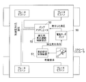
- the hydraulic pressure generated by the electric servo pump 50 is a hydraulic vehicle motion control device 52 (to distinguish it from the vehicle motion control device according to the present invention, which is a control device that controls lock prevention control and skid prevention control performed by the ABS. (Referred to as above).
- the hydraulic vehicle motion control device 52 includes a pump and an actuator 53 that can increase and decrease the hydraulic pressure.
- the hydraulic vehicle motion control device 52 collects each wheel speed, vehicle acceleration, and angular velocity (yaw rate), which are physical quantities for detecting vehicle behavior.
- the hydraulic pressure vehicle motion control device 52 performs the above-described lock prevention control in which the hydraulic pressure of the wheel is relaxed to recover from the locking tendency.
- the hydraulic vehicle motion control device 52 for example, when the steering wheel is turned in a state where the road surface friction coefficient is low, the actual turning is larger than the turning amount expected from the vehicle speed and the steering wheel angle at that time. Predicts that there is a tendency to spin, and performs the above-mentioned skid prevention control that exerts a braking force so as to suppress spin.
- FIG. 10 shows a configuration in which the conventional configuration is replaced with an electric brake.
- the vehicle integrated control device 51 transmits a braking command to the vehicle motion control device 52A based on the braking request.
- the vehicle motion control device 52A removes a pump and an actuator from the hydraulic vehicle motion control device 52 and outputs an electric signal.
- This vehicle motion control device 52A outputs the received braking command as it is in the normal state, and if the lock prevention control is operated in the non-normal state that tends to be locked, for example, the correction is performed by reducing the braking command for the corresponding wheel.
- a finished braking command is output and transmitted to the corresponding electric brake control device 54.
- the electric brake control device 54 exhibits a braking force in accordance with the received braking command.
- the vehicle can be stopped by detecting the disconnection or short circuit of the signal line and notifying the driver or disabling the drive, and guiding it to the safe side in terms of vehicle behavior I was able to. Also, when a driver's drive request is converted into a drive command and the vehicle integrated control device that transmits the command to a drive device such as an engine or a drive motor, or a similar control device becomes abnormal or temporarily functions When was stopped, no driving force was generated, and this could also be guided to the safe side in terms of vehicle behavior.
- the brake pedal that controls the braking force is made by-wire by installing an electric brake, it is considered that it will be replaced with a brake pedal having the same sensor as the accelerator pedal that is currently popular.
- An object of the present invention is a vehicle control device that controls a vehicle equipped with an electric brake, in which the complexity of the communication system is reduced and the redundancy can be increased without pressing the mounting position of the vehicle control device. It is to provide a control device.
- the vehicle control device of the present invention is a vehicle control device that controls a vehicle including an electric brake 1 that generates a pressing force on a friction member 8 by an electric actuator 4 and applies a braking force to a wheel 3.
- This vehicle control device A vehicle integrated control device 15 having a drive control function for giving a drive command to the drive source of the vehicle in response to the accelerator operation means Ap, and an integrated control function for controlling the vehicle in an integrated manner;
- An electric brake control device 14 for controlling the electric brake 1;
- a corrected braking command in which the braking command is corrected in accordance with a set rule is given to the electric brake control device 14 and the wheels 3 are controlled.
- the setting rule is, for example, a rule that is controlled according to the priority order, and is determined based on the results of tests, simulations, and the like.
- the vehicle integrated control device 15 gives a drive command to the drive source of the vehicle in response to the accelerator operation means Ap.
- the vehicle integrated control device 15 performs regenerative cooperative control in which a braking force is generated by a regenerative operation, and controls the vehicle in an integrated manner.
- the electric brake control device 14 controls the electric brake 1.
- the vehicle motion control device 16 receives a braking command from the brake operating means 2 or a braking command from the vehicle integrated control device 15 and gives a corrected braking command in which the braking command is corrected according to the set rule to the electric brake control device 14.
- the wheel 3 lock prevention control or vehicle side skid prevention control is performed.
- vehicle integrated control device 15, electric brake control device 14, and vehicle motion control device 16 are provided on independent housings or substrates, respectively.
- the vehicle integrated control device 15 and the vehicle motion control device 16 can be integrated into one, but the roles of the vehicle integrated control device 15, the electric brake control device 14, and the vehicle motion control device 16 are clarified. These are provided on independent housings or substrates.
- each of the control devices 14, 15, 16 is provided on an independent casing or board and used as a multiplex system. Even when an abnormality occurs in the braking command path, the braking force can be applied to the wheel 3 using the other braking command path. Therefore, no abnormality occurs in the entire control system that generates the braking force, and the redundancy can be increased.
- the contents to be separated are the vehicle integrated control device 15 having the drive control function and the integrated control function, the vehicle motion control device 16 having the function of lock prevention control or skid prevention control, Since the roles of the brake control device 14 are clarified and separated, and the control devices 14, 15 and 16 are provided on independent housings or substrates, the priority order of the control rules can be clearly and simplified. Therefore, the complexity of the communication system can be reduced as compared with the case where the respective control devices are integrated. In particular, since the vehicle integrated control device 15 having an integrated control function and the like and the vehicle motion control device 16 having a vehicle motion control function are separated and divided between those having greatly different roles, it is easy to clarify the roles.
- the vehicle integrated control device 15, the electric brake control device 14, and the vehicle motion control device 16 are provided on independent housings or substrates, the control devices 14, 15, and 16 are smaller than those integrated into one control device. Can be For this reason, the freedom degree at the time of mounting each control apparatus 14,15,16 in a vehicle increases, Therefore It can avoid pressing the mounting position of a vehicle control apparatus, and can improve redundancy.
- the vehicle integrated control device 15 and the vehicle motion control device 16 that respectively generate braking commands for the electric brake control device may be provided in parallel.
- both the vehicle integrated control device 15 and the vehicle motion control device 16 can detect a braking command from the brake operation means 2 and can generate a braking command to the electric brake control device 14.
- a system for supplying a braking command from the brake operating means 2 to the vehicle integrated control device 15 and a system for supplying a braking command from the brake operating means 2 to the vehicle motion control device 16 may be provided independently of each other. In this case, even if an abnormality such as disconnection occurs in one of the systems, the braking command can be transmitted using the other system.
- the vehicle integrated control device 15, the vehicle motion control device 16, and the electric brake control device 14 may have communication paths that can communicate with each other. As such a communication path that can communicate with each other, for example, control area network (CAN) control communication can be applied.
- CAN control area network
- the vehicle integrated control device 15 and the vehicle motion control device 16 calculate a reference braking command as a braking command to be transmitted to the electric brake control device 14 according to a predetermined relationship based on a braking command input to each path.
- the reference braking command calculation unit 17 may be provided. The defined relationship is determined by the result of a test or simulation, for example. In this case, each reference braking command calculation unit 17 can calculate the reference braking command with reference to a map showing the relationship between the braking command and the reference braking command.
- the vehicle integrated control device 15 includes a regenerative cooperative control unit 18 that performs a regenerative cooperative control in which the braking force actually generated differs from the reference braking command calculated by the reference braking command calculating unit 17, and this regenerative cooperative control.
- the unit 18 may increase or decrease a braking command corresponding to a braking force necessary for regenerative cooperative control with respect to the reference braking command and transmit the braking command to the electric brake control device 14.
- the regenerative cooperative control unit 18 can increase or decrease the braking command for the braking force necessary for the regenerative cooperative control.
- the regenerative cooperative control unit 18 regenerates the drive source of the vehicle, collects energy to obtain a braking force, and generates the braking force output by the electric brake 1 so that excessive braking force is not generated with respect to the braking command. Subtract.
- the vehicle motion control device 16 When the vehicle motion control device 16 performs lock prevention control or skid prevention control in which the braking force actually generated differs from the reference braking command calculated by the reference braking command calculation unit 17, the vehicle motion control device 16 locks against the reference braking command.
- a braking command corresponding to a braking force necessary for prevention control or skid prevention control may be increased or decreased and transmitted to the electric brake control device 14.
- the vehicle motion control device 16 increases or decreases the braking command for the braking force necessary for the lock prevention control with respect to the reference braking command to avoid the wheels from being completely locked.
- the vehicle motion control device 16 increases or decreases the braking command corresponding to the braking force necessary for the skid prevention control with respect to the reference braking command to avoid the vehicle from skidding.
- the vehicle integrated control device 15 and the vehicle motion control device 16 may transmit a braking command to the electric brake control device 14 only when necessary based on whether or not the control is performed. In this case, interference between the braking command between the vehicle integrated control device 15 and the electric brake control device 14 and the braking command between the vehicle motion control device 16 and the electric brake control device 14 can be avoided.
- the set priority order is set. Based on this, the priority of the braking command transmitted to the electric brake control device 14 may be determined. Even when the competing braking commands are transmitted to the electric brake control device 14, only one of the braking commands is determined, so that the braking commands can be prevented from interfering with each other.
- the electric brake control device 14 When a competing braking command is transmitted to the electric brake control device 14 as a result of execution or non-execution of the control by the vehicle integrated control device 15 and the vehicle motion control device 16, the electric brake control device 14 May select the transmitted braking command based on the set priority. Even if the competing braking commands are transmitted to the electric brake control device 14, the electric braking control device 14 selects only one of the braking commands, thereby preventing the braking commands from interfering with each other. obtain.
- the vehicle motion control device 16 transmits a reference braking command to the electric brake control device 14, and also performs the lock prevention control or the side slip prevention control.
- the vehicle integrated control device 15 may transmit a reference braking command to the electric brake control device 14. With this configuration, redundancy can be increased.
- FIG. 1 is a diagram schematically showing an electric brake 1 of a vehicle equipped with this vehicle control device.
- a vehicle for example, a four-wheel drive type electric vehicle in which front and rear wheels are independently driven by a drive motor (not shown) is applied.
- the electric brake 1 applies a braking force independently to each wheel 3 (FIG. 2) of the vehicle via the electric brake control device 14 and the like by operating a brake pedal 2 (FIG. 2) which is a brake operating means. Append.
- Each electric brake 1 includes an electric motor 4 that is an electric actuator, a speed reduction mechanism 5 that decelerates the rotation of the electric motor 4, a linear motion mechanism 6, a brake rotor 7, and a friction pad 8 that is a friction member.
- the electric motor 4, the speed reduction mechanism 5, and the linear motion mechanism 6 are incorporated in, for example, a housing not shown.
- the side closer to the outer side in the vehicle width direction of the vehicle equipped with the vehicle control device is referred to as the outboard side, and the side closer to the center of the vehicle is referred to as the inboard side.
- the speed reduction mechanism 5 is a mechanism that reduces and transmits the rotation of the electric motor 4 to the tertiary gear 10 fixed to the rotary shaft 9, and includes a primary gear 11, an intermediate gear 12, and a tertiary gear 10.
- the speed reduction mechanism 5 rotates the primary gear 11 attached to the rotor shaft 4a of the electric motor 4 by, for example, an intermediate gear 12 having a configuration in which two large and small gears are integrally stacked in the axial direction.
- transmission to the tertiary gear 10 fixed to the end of the rotary shaft 9 is enabled.
- the linear motion mechanism 6 is a mechanism that converts the rotational motion output from the speed reduction mechanism 5 into a linear motion of the linear motion portion 13 by a feed screw mechanism and causes the friction pad 8 to contact or separate from the brake rotor 7. .
- the linear motion portion 13 is supported so as to be freely rotatable in the axial direction indicated by the arrow A1.
- a friction pad 8 is provided at the end of the linear motion portion 13 on the outboard side.
- the vehicle control device mounted on the vehicle includes a vehicle integrated control device 15, an electric brake control device 14, and a vehicle motion control device 16 as shown in FIG.
- the vehicle integrated control device 15 is a predetermined conversion function stored in an LUT (Look Up Table) realized by software or hardware, or a software library, or equivalent hardware.
- Etc. hereinafter referred to as “embodiment model”
- a hardware circuit or processor capable of performing calculations for realizing a control function, an integrated control function for controlling a vehicle described later, and the like, and outputting the drive command, a braking command described later, and other control signals It consists of the above software functions.
- the vehicle motion control device 16 specifically uses the above-described embodiment model, as will be described in detail later, a braking command from the brake pedal 2 serving as a brake operating means or a braking command from the vehicle integrated control device 15.
- the corrected braking command obtained by correcting the braking command is output to the electric brake control device 14 in accordance with setting rules defined in the program (rules to be controlled in accordance with the priority order, which will be described later).
- 3 is constituted by a hardware circuit or a software function on a processor capable of performing an operation for realizing the lock prevention control 3 or the vehicle skid prevention control.
- the electric brake control device 14 receives the input of the braking command or the corrected braking command using the above-described embodiment model, and rotates the rotational speed and rotational speed of the electric motor 4 or the brake rotor 7. It is composed of a hardware circuit or a software function on a processor that can calculate and output the pressing force to the friction pad 8 and control the corresponding electric brake 1.
- control related to braking and the control performed by the vehicle motion control device 16 and the electric brake control device 14 are the following three.
- Vehicle integrated control device 15 When a braking request is input as in the regenerative cooperative control, a braking force is generated by regeneration of a vehicle drive motor (not shown), and the braking force does not operate the electric brake 1, that is, the vehicle It is a control that integrates various information and cooperates with components other than the brake.
- hill hold control for preventing the slope from slipping down, or changing the relationship between the brake depression amount and the braking force to be generated according to the vehicle speed, that is, the depression amount of the brake pedal 2 and the electric drive The control deviates from the relationship with the braking force generated by the brake 1, and it is possible to travel safely even if these do not work.
- Vehicle motion control charge Vehicle motion control device 16
- a preset risk is set.
- the control is to increase or decrease the braking force without depending on the braking request. For example, if the wheel 3 tends to lock, the braking force of the corresponding wheel 3 is reduced, and if the vehicle is about to spin rightward, the braking force is generated on the left wheel 3 to suppress the spin.
- These controls are performed in a dangerous state to improve safety, but these controls are not performed for many hours of driving, and even in situations where a dangerous state is determined, If an appropriate driving operation is performed, it is possible to travel.
- Braking force generation control charge Electric brake control device 14 As shown in FIG. 1, the electric brake control device 14 drives the electric motor 4 that is an electric actuator based on the braking command determined by the braking request, and generates a pressing force to the brake rotor 7 on the friction pad 8. Thus, control for generating a braking force is performed. This control is always performed unless a reasonable judgment is made for a special reason. As an example of a reasonable judgment for this special reason, for example, when an abnormality has occurred in some of the components of the electric brake 1, it is determined that a significantly large braking force is generated with respect to the braking command. This is a case where it is determined that no braking force is generated in order not to disturb the vehicle behavior (for example, to avoid locking only one wheel).
- the braking force generation control can be performed in any case as long as the braking command can be transmitted to the electric brake control device 14. It is assumed that this is also implemented in
- the braking force generation control is in the order of 1 ⁇ 2 ⁇ 3 in order of increasing complexity of control, which requires more device information. Further, from the viewpoint of preventing accidents, even if the function is limited due to an abnormality or the like, the order of priority of control to be maintained without stopping control is 3 ⁇ 2 ⁇ 1. This is the same when, for example, the controls 1 and 2 are performed normally and simultaneously, and the basic rule is that 2 is prioritized assuming that the control 3 is always performed. Therefore, it is desirable that the vehicle configuration be configured so that reliability can be ensured in the order of 3 ⁇ 2 ⁇ 1 when an abnormality occurs in a component while efficiently performing three controls when there is no abnormality in the component.
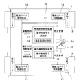
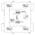
- FIG. 2 shows a multiplexing configuration by separating and arranging the vehicle integrated control device 15 and the vehicle motion control device 16 that realize the above requirements.
- one electric brake control device 14 is arranged for each electric brake 1 of each wheel 3.
- the corresponding electric brake control device is provided. It is good also as a structure which integrated 14 and reduced the quantity.
- the brake pedal 2 is provided with a plurality of sensors 2a (here, referred to as stroke sensors 2a) for detecting the depression amount.
- Each stroke sensor 2a has an independent structure, and signal lines for transmitting respective output signals are separately connected to the vehicle integrated control device 15 and the vehicle motion control device 16 through independent signal lines. .
- the vehicle integrated control device 15, the electric brake control device 14, and the vehicle motion control device 16 are provided on independent housings or substrates, respectively.
- an electric control unit (ECU) is applied as the vehicle integrated control device 15, for example.
- the vehicle integrated control device 15, the vehicle motion control device 16, and all the electric brake control devices 14 are connected to one communication system.
- control area network (CAN) control communication is premised, but at least the vehicle integrated control device 15 and the vehicle motion control device 16 can communicate bidirectionally, and these two control devices 15 and 16 are each electrically driven.
- a communication system that can transmit commands to the brake control device 14 may be used.
- the vehicle integrated control device 15 and the vehicle motion control device 16 are arranged in parallel, both of which can detect the driver's braking request, that is, the braking command from the brake pedal 2, and the braking command. Can be generated. For this reason, even when an abnormality occurs in any one of the command generation paths, the abnormality does not occur in the entire control system that generates the braking force.
- the vehicle integrated control device 15 and the vehicle motion control device 16 can be integrated into one, but as described above, the roles of the vehicle integrated control device 15 and the vehicle motion control device 16 are clarified. Redundancy can be improved by forming and using a multiplex system with these two control devices 15 and 16 after being installed separately in independent housings or substrates.
- the vehicle integrated control device 15 and the vehicle motion control device 16 are divided into the roles of the vehicle integrated control device 15 and the vehicle motion control device 16 by mounting a plurality of arithmetic units (CPUs) even when the housing and the board are integrated.
- CPUs arithmetic units
- braking requests are input to the vehicle integrated control device 15 and the vehicle motion control device 16 from the brake pedal 2 using the respective paths. Since this braking request is an amount indicating the physical depression amount of the brake pedal 2, it cannot be actually braked unless it is converted into a pressing force of the electric brake 1 of each wheel 3 and is not a pressing command. . Therefore, both the control devices 15 and 16 perform an operation for converting the braking request into a command value of the pressing force, that is, the braking command, before performing the above-described additional control and vehicle motion control.
- This calculation is performed, for example, by referring to a map such as a preset pedal depression amount and a braking command for each wheel 3.
- the braking command obtained as a result becomes a reference value when the vehicle integrated control and the vehicle motion control are performed, and this is used as the reference braking command.
- the vehicle integrated control device 15 and the vehicle motion control device 16 each have a reference braking command calculation unit 17, and each reference braking command calculation unit 17 specifically uses the above-described embodiment model to generate the brake pedal 2.
- a reference braking command serving as a reference to be transmitted to the electric brake control device 14 is calculated and output according to the relationship defined in the map or the like stored in the LUT. It consists of possible hardware circuits or software functions on the processor.
- each reference braking command calculation unit 17 obtains a reference braking command from the braking request.
- This reference braking command is a braking command for the vehicle integrated control device 15 when the additional control is not performed, and a braking command for the vehicle motion control device 16 when the vehicle motion control is not performed.
- additional controls for example, regenerative cooperative control
- a part of the braking force required from the braking request according to various information of the vehicle is not covered by the regenerative operation of the drive motor.
- a corrected braking command corrected by subtracting the minute from the reference braking command is determined.
- additional control hill hold and anti-slip control anti-spin prevention can also be used for the reference braking command (same as there is no pedal operation and no command).
- a braking force required by each control is applied to determine a braking command.
- the driver's braking request is input to the vehicle via the stroke sensor 2a of the brake pedal 2.
- the input braking request is input to both the vehicle integrated control device 15 and the vehicle motion control device 16, and each reference braking command calculation unit 17 of the vehicle integrated control device 15 and the vehicle motion control device 16 performs the reference as described above.
- a braking command is obtained by calculation.
- the vehicle motion control device 16 does not perform the vehicle motion control, and the vehicle integrated control device 15 does not perform the additional control (normally this time) State).
- the reference braking command calculated by the reference braking command calculation unit 17 in the vehicle integrated control device 15 is transmitted to the electric brake control device 14.
- the vehicle motion control device 16 operates so as not to interfere with the transmission of the braking command between the vehicle integrated control device 15 and the electric brake control device 14 (for example, the vehicle motion control device 16 does not transmit the braking command).
- the electric brake control device 14 does not select it.
- the braking command transmitted by the vehicle integrated control device 15 is adopted.
- the vehicle integrated control device 15 performs additional control.
- the vehicle integrated control device 15 includes a regenerative cooperative control unit 18 that performs regenerative cooperative control as additional control.
- the regenerative cooperative control unit 18 uses the above-described realization model, the subtraction function, and hardware equivalent thereto to regenerate the vehicle drive motor and collect the braking force while collecting energy.
- the subtraction operation is performed by subtracting the regenerative amount from the braking force output by the electric brake 1 in accordance with this. It is composed of a hardware circuit that can output a braking command or a software function on the processor. The braking force output from the electric brake 1 determined in this way is converted into a braking command and transmitted to the electric brake control device 14.
- the entire vehicle can be braked without excess or deficiency with respect to the braking request by the braking force generated by the regeneration of the drive motor and the braking force generated by the electric brake 1.
- the vehicle motion control device 16 has no vehicle motion control to be performed, and operates so as not to interfere with transmission of a braking command between the vehicle integrated control device 15 and the electric brake control device 14 (for example, the vehicle motion control device 16 Does not transmit a braking command, or even if the vehicle motion control device 16 transmits a braking command, it is not selected by the electric brake control device 14), which is the same as in the normal state.
- vehicle motion control is further performed during the normal state or additional control described above.
- lock prevention control is performed as vehicle motion control.
- the vehicle motion control device 16 transmits a braking command to the electric brake control device 14 corresponding to the wheel 3 with a value smaller than the value obtained from the braking request.
- the braking command transmitted by the vehicle motion control device 16 in a state where the vehicle motion control is being performed needs to have priority over the braking command transmitted by the vehicle integrated control device 15. . Therefore, for example, when the vehicle motion control device 16 declares that the vehicle motion control is being performed, the vehicle integrated control device 15 stops the transmission of the braking command, or the vehicle motion control device 16 and the vehicle integrated control device 15. The priority of the braking command is maintained by giving priority to the communication transmitted by the vehicle motion control device 16 when the communication is competing or by selecting it in the electric brake control device 14.
- the braking operation is controlled so that at least the braking force exerted by each wheel determined by the vehicle motion control device 16 is satisfied.
- each control device 15, 16 transmits a braking command to the electric brake control device 14, when this is performed by communication, a communication message for transmitting the command
- the received electric brake control device 14 refers to this by adding the data indicating the state to. Specifically, when the vehicle integrated control device 15 performs additional control, this data is changed to a value indicating that additional control is being performed.
- this data is changed to a value indicating that the vehicle motion control is being performed.
- the electric brake control device 14 that has received both data can employ the braking command transmitted by the vehicle motion control device 16 having a higher priority with reference to these data.
- Detection and notification of disconnection or short circuit is performed by a disconnection / short circuit detection method (for example, Patent Documents 1 to 3 described above) conventionally used in connected control devices.
- the control device 15 (16) that has detected its own disconnection and short circuit declares on the communication that it cannot issue a braking command to the other control device 16 (15). Declaring that the braking command transmitted by the driver has priority, the electric brake control device 14 can rationally select the braking command.
- the control device 15 (16) is controlled by the other control device 16 (15). On the other hand, it is performed by declaring on the communication that the braking command cannot be transmitted by itself.
- the control device 15 (16) self-diagnosed as abnormal stops communication a bus-off specified by a standard such as CAN communication occurs, and the other control device 16 (15) detects the bus-off.
- the control device 15 (16) self-diagnosed as abnormal stops communication and the other control device 16 (15) detects that the control device 15 (16) without communication is abnormal because there is no communication for a certain period of time.
- the vehicle integrated control device 15 or the signal line between the vehicle integrated control device 15 and the stroke sensor 2a is disconnected or short-circuited or a malfunction of the stroke sensor 2a occurs while the vehicle is running.
- the vehicle motion control device 16 operating normally finds that the braking command transmitted by the vehicle motion control device 16 has priority from the above-described detection and notification method, the stroke sensor 2a connected to the vehicle motion control device 16 is recognized.
- the required braking force can be generated by converting the braking request output by the control signal into a reference braking command and transmitting it to the electric brake control device 14.
- the vehicle motion control device 16 can perform the lock prevention control similarly to the case where there is no functional abnormality. .
- the vehicle motion control device 16 or a signal line between the vehicle motion control device 16 and the stroke sensor 2a is disconnected or short-circuited or a malfunction of the stroke sensor 2a occurs while the vehicle is running.
- the vehicle integrated control device 15 operating normally finds that the braking command transmitted by the vehicle integrated control device 15 has priority from the detection and notification methods described above, the stroke sensor 2a connected to the vehicle integrated control device 15 is used.
- a necessary braking force can be generated.
- vehicle motion control cannot be performed when vehicle motion control becomes necessary, the driver is informed of abnormality information at an early stage to urge the driver to perform inspection and repair.
- the vehicle motion control device 16 when the vehicle motion control device 16 is normal and an abnormality occurs in the stroke sensor 2a connected to the vehicle motion control device 16 or its signal line, the vehicle motion control device 16 The abnormal state is transmitted to the vehicle integrated control device 15 by communication, and the braking request acquired by the vehicle integrated control device 15 is transmitted to the vehicle motion control device 16. Thereby, since the vehicle motion control apparatus 16 can use the braking request
- the above-mentioned data indicating the state added to the communication message for command transmission when the control devices 15 and 16 declare an abnormality as described above may be used. Specifically, when any one of the control devices 15 (16) makes a self-diagnosis that is abnormal, the data is changed to a value indicating abnormality.
- the other control device 16 (15) or the electric brake control device 14 that has received the data indicating the abnormality refers to the data indicating the abnormality and takes measures to prevent the abnormality of the function that generates the braking force as described above. Can take.
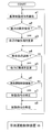
- FIG. 3 for the vehicle integrated control device 15, FIG. 4 for the vehicle motion control device 16, and FIG. 5 for the electric brake control device 14.
- FIG. 3 for the vehicle integrated control device 15, FIG. 4 for the vehicle motion control device 16, and FIG. 5 for the electric brake control device 14.
- the vehicle integrated control device 15 communicates with the drive device of the drive motor to perform regenerative braking. Or collecting information from various sensors is omitted for convenience of explanation.
- description will be made with reference to FIG. 2 as appropriate.
- the reference braking command calculation unit 17 of the vehicle integrated control device 15 outputs a reference braking command as a braking command to be transmitted to the electric brake control device 14.
- the vehicle integrated control device 15 determines whether or not a signal indicating a malfunction of the other vehicle motion control device 16 has been received (step a2).
- step a2 determines whether or not a signal such as a malfunction is received (step a2: yes)
- the vehicle integrated control device 15 declares that the braking command transmitted by itself has priority (step a3), and then proceeds to step a4.
- step a2 when the vehicle integrated control device 15 does not receive a signal indicating a malfunction of the vehicle motion control device 16 (step a2: no), the process proceeds to step a4.
- step a4 the vehicle integrated control device 15 determines its own abnormality by the self-diagnosis function.
- step a4 yes
- the vehicle integrated control device 15 declares an abnormality to the vehicle motion control device 16 (step a5).
- step a4 no
- it is determined whether or not to perform vehicle integrated control as additional control step a6).
- step a6 yes
- the vehicle integrated control device 15 corrects the braking command (step a7), and transmits the braking command to the electric brake control device 14 (step a8).
- step a6: no the process proceeds to step a8, and the vehicle integrated control device 15 transmits the braking command without correcting the braking command.
- step a6 ′ in FIG. 4, “execution of vehicle motion control” is determined, unlike “execution of vehicle integrated control” in a6 of FIG.
- step b 1 After starting the control flow of the electric brake control device 14, when the electric brake control device 14 receives a braking command (step b 1), any of the vehicle motion control device 16 and the vehicle integrated control device 15 is selected. It is confirmed whether the brake command to be transmitted has priority (step b2). If the braking command transmitted by the vehicle motion control device 16 has priority (step b3: yes), the electric brake control device 14 selects the braking command transmitted by the vehicle motion control device 16 (step b4).
- step b3 When the braking command transmitted from the vehicle motion control device 16 has no priority (step b3: no), the electric brake control device 14 selects the braking command transmitted from the vehicle integrated control device 15 (step b5). Thereafter, the electric brake control device 14 causes the electric brake 1 to exert a braking force based on the selected braking command (step b6).
- the vehicle integrated control device 15, the electric brake control device 14, and the vehicle motion control device 16 are provided in independent housings or substrates and used as a multiplex system. Even when an abnormality occurs in one of the braking command paths, the braking force can be applied to the wheel using the other braking command path. Therefore, no abnormality occurs in the entire control system that generates the braking force, and the redundancy can be increased.
- the contents to be separated are the vehicle integrated control device 15 having the drive control function and the integrated control function, the vehicle motion control device 16 having the function of lock prevention control or skid prevention control, Since the roles of the brake control device 14 are clarified and separated, and the control devices 14, 15 and 16 are provided on independent housings or substrates, the priority order of the control rules can be clearly and simplified. Therefore, the complexity of the communication system can be reduced as compared with the case where the respective control devices are integrated. In particular, since the vehicle integrated control device 15 having an integrated control function and the like and the vehicle motion control device 16 having a vehicle motion control function are separated and divided between those having greatly different roles, it is easy to clarify the roles.
- the vehicle integrated control device 15, the electric brake control device 14, and the vehicle motion control device 16 are provided on independent housings or substrates, the control devices 14, 15, and 16 are smaller than those integrated into one control device. Can be For this reason, the freedom degree at the time of mounting each control apparatus 14,15,16 in a vehicle increases, Therefore It can avoid pressing the mounting position of a vehicle control apparatus.
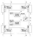
- FIG. 6 is a block diagram of a control system showing a configuration in which only pressing requests are arranged in parallel.
- there are two independent stroke sensors 2a in this embodiment, there are two sensors 2a
- the vehicle integrated control device 15 and the vehicle motion control device 16 are independent of each other but in series. It is the structure connected to.
- the electric brake control device 14 and the vehicle motion control device 16 are more protected than the other components of the vehicle so that no abnormality occurs in the generation of braking force as a design for vehicle safety, for example,
- the vehicle motion control device 16 generates a braking command, so that the braking force generation control can be performed.
- the braking force can be exerted as intended by the driver. Therefore, there is an advantage that the redundancy of the entire vehicle is higher than the configuration of FIG.
- FIG. 7 the configuration of FIG. 7 is also conceivable.
- the vehicle integrated control device 15 and the vehicle motion control device 16 are independent and are installed in parallel with the electric brake control device 14.
- the stroke sensor 2 a has only one system and is connected to the vehicle integrated control device 15.
- the vehicle integrated control device 15, which plays various roles such as vehicle braking / driving, power management, notification to the driver, etc., is configured such that the function is not stopped even if the function is limited by possible means, for example, a power supply It is assumed that this is realized by redundancy of the CPU and various components of the control device.
- FIG. 8 is also conceivable.
- the configuration of FIG. 8 is characterized in that the vehicle integrated control device and the vehicle motion control device as shown in FIG. 10 are arranged in series, and a pressing request as shown in FIG. 2 is input to the vehicle integrated control device and the vehicle motion control device.
- These two control devices 15 and 16 and the electric brake control device 14 have both the characteristics of being arranged in parallel.
- the priority of command transmission by arranging the control devices 15 and 16 in series is simplified while all of them are operating normally while satisfying the redundancy ensured so far.
- a higher-level control device can determine a control content with higher importance and transmit it to a lower-level control device, or implement the control content). It can be said that there is.
- an electric vehicle that drives either a front wheel or a rear wheel with a drive motor may be applied, or a hybrid that drives either a front wheel or a rear wheel with a drive motor and drives the other with an internal combustion engine.
- a car of the type may be applied.
Landscapes
- Engineering & Computer Science (AREA)
- Transportation (AREA)
- Mechanical Engineering (AREA)
- Regulating Braking Force (AREA)
- Braking Systems And Boosters (AREA)
Abstract
通信系の煩雑さの低減を図ると共に、車両制御装置の搭載位置を圧迫することなく冗長性を高めることができる車両制御装置を提供する。この車両制御装置は、アクセル操作手段(Ap)に応答して車両の駆動源に駆動指令を与える駆動制御機能、および車両を統合して制御する統合制御機能を有する車両統合制御装置(15)と、電動ブレーキ(1)を制御する電動ブレーキ制御装置(14)と、ブレーキ操作手段(2)からの制動指令または車両統合制御装置(15)からの制動指令を受けて、設定規則に従い前記制動指令を補正した補正済制動指令を電動ブレーキ制御装置(14)に与えてロック防止制御または横滑り防止制御を行う車両運動制御装置(16)とを備える。これら車両統合制御装置(15)と電動ブレーキ制御装置(14)と車両運動制御装置(16)とをそれぞれ独立した筐体または基板に設けた。
Description
本出願は、2015年1月8日出願の特願2015-001994の優先権を主張するものであり、その全体を参照により本願の一部をなすものとして引用する。
この発明は、電動ブレーキを備えた車両を制御する車両制御装置に関し、電動ブレーキシステムの冗長性を高めることができる車両制御装置に関する。
[従来の液圧を用いた制動系における構成と電動ブレーキを用いた場合の構成の違い]
最初に従来型の液圧を用いた制動系の構成について考える。ここで取り扱う制動系の構成は、最も簡単な、ブレーキペダルが液圧系のマスターシリンダに接続されたものではなく、図9に示すように、ブレーキペダルと液圧系の間にストロークシュミレータを備え、液圧は電動サーボポンプ50によって得る構成である。液圧を発生させる電動サーボポンプ50への液圧発生指令は、ストロークシミュレータに取り付けたストロークセンサなどにより取り込んだ運転者からの制動要求(押圧要求とも呼ぶ)を基に、車両統合制御装置51が算出し伝達している。
最初に従来型の液圧を用いた制動系の構成について考える。ここで取り扱う制動系の構成は、最も簡単な、ブレーキペダルが液圧系のマスターシリンダに接続されたものではなく、図9に示すように、ブレーキペダルと液圧系の間にストロークシュミレータを備え、液圧は電動サーボポンプ50によって得る構成である。液圧を発生させる電動サーボポンプ50への液圧発生指令は、ストロークシミュレータに取り付けたストロークセンサなどにより取り込んだ運転者からの制動要求(押圧要求とも呼ぶ)を基に、車両統合制御装置51が算出し伝達している。
このような構成としている理由は、ハイブリッド車両または電気自動車において、航続距離を延ばす目的で、モータで回生発電させる一方、当該回生動作により制動力が得られるので、液圧系での制動力を減少させることで、全体として制動力を制動要求と一致させる回生協調制動を実施する必要があるからであり、ブレーキペダルと液圧の関係を任意に決定できる上記のような構成とする必要がある。
電動サーボポンプ50が発生した液圧は、ABSが実施するロック防止制御や横滑り防止制御を統括する制御装置である、液圧用車両運動制御装置52(本発明における車両運動制御装置と区別するため、このように呼称する)に接続される。この液圧用車両運動制御装置52は液圧の加減圧が可能なポンプおよびアクチュエータ53を備えている。液圧用車両運動制御装置52は、車両挙動を検知する物理量である、各車輪速、車両加速度、角速度(ヨーレート)を収集している。
例えば、路面摩擦係数が低い状態でブレーキペダルを踏み制動を開始したとき、直前の車両速度と車両加速度に比べてある車輪の車輪速が急激に減少した場合は、車輪がロック傾向にあると考えられる。このため、その車輪の液圧を緩めて、ロック傾向から復帰させる上記のロック防止制御を液圧用車両運動制御装置52が行う。また、液圧用車両運動制御装置52は、例えば、路面摩擦係数が低い状態でハンドルを切ったとき、そのときの車速とハンドル角から予想される旋回量よりも実際の旋回が過大である場合には、スピン傾向にあると予想し、スピンを抑制するように制動力を発揮する上記の横滑り防止制御を行う。
従来型の液圧を用いた制動系の場合は、ロック防止制御や横滑り防止制御を実施するためには、その制動力の発生媒体であり指令の伝達方法であるブレーキフルードを加減圧するポンプやアクチュエータが必要であった。しかし、電動ブレーキを搭載した車両においては、このようなポンプやアクチュエータを必要とせず、同様の指令を生成する制御装置を用意すればよい。
[従来の液圧を用いた制動系における構成を電動ブレーキに置き換えた構成]
以上を基に、従来の構成を電動ブレーキに置き換えた構成を図10に示す。車両統合制御装置51は、制動要求を基に、制動指令を車両運動制御装置52Aへ伝達する。車両運動制御装置52Aは、前記液圧用車両運動制御装置52からポンプやアクチュエータを取り除き、電気信号を出力するようにしたものである。
以上を基に、従来の構成を電動ブレーキに置き換えた構成を図10に示す。車両統合制御装置51は、制動要求を基に、制動指令を車両運動制御装置52Aへ伝達する。車両運動制御装置52Aは、前記液圧用車両運動制御装置52からポンプやアクチュエータを取り除き、電気信号を出力するようにしたものである。
この車両運動制御装置52Aは、通常状態では受信した制動指令をそのまま出力し、例えばロック傾向となる非通常状態でロック防止制御が働けば、該当する車輪の制動指令を減少させて補正された補正済制動指令を出力し、該当する電動ブレーキ制御装置54に伝達する。電動ブレーキ制御装置54は、受信した制動指令に従い、制動力を発揮する。以上の構成において、特許文献1~5を参考に各種異常時の予防策を述べる。
車両の機械要素を制御する際に機械的接続を断ち、バイワイヤと呼ばれる電圧信号や電気的な信号により要求や指令の伝達を行って、車両の制駆動や旋回を制御する技術において、いち早く普及が進んでいる駆動要求を決定するアクセルペダルは、踏み込み量を検出するセンサ、多くの場合はストロークセンサを用いて駆動要求を検出している。このアクセルペダルに取り付けられたセンサ出力を伝達する信号線については、信号線の断線や短絡を検知する方法が提案され、普及している(特許文献1~5)。
駆動要求を決定するアクセルペダルについては、信号線の断線や短絡を検知し、運転者に報知するか、駆動を不許可とすることで、車両は停止でき、車両挙動上安全側に誘導することができた。また、運転者の駆動要求を駆動指令に変換し、例えばエンジンや駆動モータのような駆動装置に指令を伝達する車両統合制御装置や、それに類する制御装置が異常となった場合または一時的に機能を停止した場合、駆動力が発生されず、こちらも車両挙動上安全側に誘導することができた。
ここで、制動力を制御するブレーキペダルが、電動ブレーキの搭載によりバイワイヤ化されれば、現在普及しているアクセルペダルと同様のセンサを持つブレーキペダルに置き換わると考えられる。
しかし、アクセルペダルと異なりブレーキペダルの場合は、信号線の断線や短絡、制御装置の異常もしくは一時的な機能停止を検知し報知して、かつ運転者からの上記制動要求に応じて制動力を発揮できなければ、車両挙動上安全側に誘導することができない。そのため、制動要求を制動指令に変換し、電動ブレーキに伝達する信号経路の可用性を高めることが必要である。しかし、単純に可用性を高めるために多重化するだけでは、制御則の優先順位の妥当性が維持できなかったり、通信系の煩雑さの向上やコストアップしたり、制御装置の搭載位置を圧迫するなど問題があった。
以上の問題点により、通信と制御系の全損失の状態を除き、一部の構成要素の機能が喪失した場合においても、運転者の制動要求に対し、制動力を発揮することができる構成とする必要があった。
この発明の目的は、電動ブレーキを備えた車両を制御する車両制御装置において、通信系の煩雑さの低減を図ると共に、車両制御装置の搭載位置を圧迫することなく冗長性を高めることができる車両制御装置を提供することである。
以下、この発明について、理解を容易にするために、便宜上実施形態の符号を参照して説明する。
この発明の車両制御装置は、電動アクチュエータ4により摩擦部材8に押圧力を発生させて車輪3に制動力を与える電動ブレーキ1を備えた車両を制御する車両制御装置であって、
この車両制御装置は、
アクセル操作手段Apに応答して前記車両の駆動源に駆動指令を与える駆動制御機能、および前記車両を統合して制御する統合制御機能を有する車両統合制御装置15と、
前記電動ブレーキ1を制御する電動ブレーキ制御装置14と、
ブレーキ操作手段2からの制動指令または前記車両統合制御装置15からの制動指令を受けて、設定規則に従い前記制動指令を補正した補正済制動指令を前記電動ブレーキ制御装置14に与えて前記車輪3のロック防止制御または前記車両の横滑り防止制御を行う車両運動制御装置16と、
を備え、
これら車両統合制御装置15と電動ブレーキ制御装置14と車両運動制御装置16とをそれぞれ独立した筐体または基板に設けている。
前記設定規則は、例えば、優先順位に従って制御する規則であり、試験やシミュレーション等の結果により定められる。
この車両制御装置は、
アクセル操作手段Apに応答して前記車両の駆動源に駆動指令を与える駆動制御機能、および前記車両を統合して制御する統合制御機能を有する車両統合制御装置15と、
前記電動ブレーキ1を制御する電動ブレーキ制御装置14と、
ブレーキ操作手段2からの制動指令または前記車両統合制御装置15からの制動指令を受けて、設定規則に従い前記制動指令を補正した補正済制動指令を前記電動ブレーキ制御装置14に与えて前記車輪3のロック防止制御または前記車両の横滑り防止制御を行う車両運動制御装置16と、
を備え、
これら車両統合制御装置15と電動ブレーキ制御装置14と車両運動制御装置16とをそれぞれ独立した筐体または基板に設けている。
前記設定規則は、例えば、優先順位に従って制御する規則であり、試験やシミュレーション等の結果により定められる。
この構成によると、車両統合制御装置15はアクセル操作手段Apに応答して車両の駆動源に駆動指令を与える。また車両統合制御装置15は、回生動作により制動力の生じる回生協調制御を行い、また車両を統合して制御する。電動ブレーキ制御装置14は電動ブレーキ1を制御する。車両運動制御装置16は、ブレーキ操作手段2からの制動指令または車両統合制御装置15からの制動指令を受けて、設定規則に従い前記制動指令を補正した補正済制動指令を電動ブレーキ制御装置14に与えて車輪3のロック防止制御または車両の横滑り防止制御を行う。
これら車両統合制御装置15と電動ブレーキ制御装置14と車両運動制御装置16とをそれぞれ独立した筐体または基板に設けている。ここで、例えば車両統合制御装置15と車両運動制御装置16を一つに統合することも可能であるが、車両統合制御装置15と電動ブレーキ制御装置14と車両運動制御装置16の役割を明確化し、それぞれ独立した筐体または基板に設ける。
このように各制御装置14,15,16の役割を明確化し、それぞれ独立した筐体または基板に設けて多重系として活用するため、車両統合制御装置15と車両運動制御装置16のいずれか一方の制動指令の経路に異常が発生した場合においても、他方の制動指令の経路を用いて車輪3に制動力を与えることができる。したがって、制動力を発生する制御系全体に異常が発生せずその冗長性を高め得る。また、単に多重化するものと異なり、分離する内容を、駆動制御機能および統合制御機能を持つ車両統合制御装置15と、ロック防止制御または横滑り防止制御という機能を持つ車両運動制御装置16と、電動ブレーキ制御装置14とに役割を明確化して分離し、かつ各制御装置14,15,16をそれぞれ独立した筐体または基板に設けたため、制御則の優先順位を明確かつ単純化できる。したがって、各制御装置を統合したものよりも通信系の煩雑さの低減を図ることができる。特に統合制御機能等を持つ車両統合制御装置15と、車両運動制御機能を持つ車両運動制御装置16とを分離し、それぞれの役割が大きく異なるものの間で分割したため、役割の明確化が行い易い。
また車両統合制御装置15と電動ブレーキ制御装置14と車両運動制御装置16とをそれぞれ独立した筐体または基板に設けたため、各制御装置14,15,16を一つの制御装置に統合するよりも小型化できる。このため、各制御装置14,15,16を車両に搭載する際の自由度が高まり、よって車両制御装置の搭載位置を圧迫することを回避し、冗長性を高め得る。
前記電動ブレーキ制御装置に対する制動指令をそれぞれ生成する前記車両統合制御装置15と前記車両運動制御装置16を並列に設けても良い。この場合、車両統合制御装置15と車両運動制御装置16の両方がブレーキ操作手段2からの制動指令を検出することができ、かつ電動ブレーキ制御装置14への制動指令を生成することができる。
前記ブレーキ操作手段2から前記車両統合制御装置15に制動指令を与える系統と、前記ブレーキ操作手段2から前記車両運動制御装置16に制動指令を与える系統とを互いに独立して設けても良い。この場合、いずれか一方の系統に断線等の異常が発生しても、他方の系統を用いて制動指令を伝達することができる。
前記車両統合制御装置15と前記車両運動制御装置16と前記電動ブレーキ制御装置14はそれぞれ相互に通信できる通信経路を有するものとしても良い。このような相互に通信できる通信経路として、例えば、コントロールエリアネットワーク(CAN:Control Area Network)通信を適用し得る。
前記車両統合制御装置15および前記車両運動制御装置16は、それぞれの経路に入力された制動指令に基づき、定められた関係に従って前記電動ブレーキ制御装置14に伝達すべき制動指令として基準制動指令を演算する基準制動指令演算部17をそれぞれ有するものとしても良い。前記定められた関係は、例えば、試験やシミュレーション等の結果により定められる。この場合、各基準制動指令演算部17は、例えば、制動指令と基準制動指令との関係を示したマップのようなものを参照して、基準制動指令を演算することができる。
前記車両統合制御装置15は、前記基準制動指令演算部17で演算される基準制動指令とは実際に発生させる制動力が異なる回生協調制御を行う回生協調制御部18を有し、この回生協調制御部18は、前記基準制動指令に対し回生協調制御に必要な制動力分の制動指令を増減させて前記電動ブレーキ制御装置14に伝達するものとしても良い。この場合、基準制動指令演算部17で演算される基準制動指令に対し、回生協調制御部18は、回生協調制御に必要な制動力分の制動指令を増減させ得る。例えば、回生協調制御部18は、車両の駆動源を回生動作させエネルギーを回収し制動力を得て、制動指令に対して過剰な制動力が発生しないように電動ブレーキ1が出力する制動力を差し引く。
前記車両運動制御装置16は、前記基準制動指令演算部17で演算される基準制動指令とは実際に発生させる制動力が異なるロック防止制御または横滑り防止制御を行うとき、前記基準制動指令に対しロック防止制御または横滑り防止制御に必要な制動力分の制動指令を増減させて前記電動ブレーキ制御装置14に伝達するようにしても良い。車両運動制御としてロック防止制御を行う場合、車両運動制御装置16は、基準制動指令に対しロック防止制御に必要な制動力分の制動指令を増減させて車輪が完全にロックすることを回避する。車両運動制御として横滑り防止制御を行う場合、車両運動制御装置16は、基準制動指令に対し横滑り防止制御に必要な制動力分の制動指令を増減させて車両が横滑りすることを回避する。
前記車両統合制御装置15および前記車両運動制御装置16は、それぞれの制御の実施、不実施に基づき、必要なときにだけ前記電動ブレーキ制御装置14に対し制動指令を伝達するようにしても良い。この場合、車両統合制御装置15と電動ブレーキ制御装置14間の制動指令と、車両運動制御装置16と電動ブレーキ制御装置14間の制動指令とが互いに干渉することを未然に回避することができる。
前記車両統合制御装置15および前記車両運動制御装置16による、それぞれの制御の実施、不実施の結果、競合する制動指令が前記電動ブレーキ制御装置14に対し送信されたとき、設定された優先順位に基づき、前記電動ブレーキ制御装置14に伝達される制動指令の優先度が決定されるようにしても良い。このように競合する制動指令が電動ブレーキ制御装置14に対し送信されたとしても、いずれか一方の制動指令のみが決定されるため、制動指令が互いに干渉することを回避し得る。
前記車両統合制御装置15および前記車両運動制御装置16による、それぞれの制御の実施、不実施の結果、競合する制動指令が前記電動ブレーキ制御装置14に対し送信されたとき、前記電動ブレーキ制御装置14は、設定された優先順位に基づき、伝達された制動指令を取捨選択するようにしても良い。このように競合する制動指令が電動ブレーキ制御装置14に対し送信されたとしても、電動ブレーキ制御装置14がいずれか一方の制動指令のみを選択することで、制動指令が互いに干渉することを回避し得る。
前記車両統合制御装置15に異常が発生したとき、前記車両運動制御装置16が、基準制動指令を前記電動ブレーキ制御装置14に伝達し、且つ、前記ロック防止制御または前記横滑り防止制御も実施するようにしても良い。また、前記車両運動制御装置16に異常が発生したとき、前記車両統合制御装置15が、基準制動指令を前記電動ブレーキ制御装置14に伝達するようにしても良い。この構成により、冗長性を高めることができる。
請求の範囲および/または明細書および/または図面に開示された少なくとも2つの構成のどのような組合せも、この発明に含まれる。特に、請求の範囲の各請求項の2つ以上のどのような組合せも、この発明に含まれる。
この発明は、添付の図面を参考にした以下の好適な実施形態の説明から、より明瞭に理解されるであろう。しかしながら、実施形態および図面は単なる図示および説明のためのものであり、この発明の範囲を定めるために利用されるべきものではない。この発明の範囲は添付の請求の範囲によって定まる。添付図面において、複数の図面における同一の符号は、同一または相当する部分を示す。
この発明の一実施形態に係る車両制御装置を図1ないし図5と共に説明する。図1は、この車両制御装置を搭載した車両の電動ブレーキ1を概略示す図である。車両として、例えば、前後の各車輪を駆動モータ(不図示)で独立に駆動する四輪駆動式の電気自動車が適用される。電動ブレーキ1は、ブレーキ操作手段であるブレーキペダル2(図2)の操作により、電動ブレーキ制御装置14等を介して、車両の各車輪3(図2)に対してそれぞれ独立して制動力を付加する。
各電動ブレーキ1は、それぞれ電動アクチュエータである電動モータ4と、この電動モータ4の回転を減速する減速機構5と、直動機構6と、ブレーキロータ7と、摩擦部材である摩擦パッド8とを有する。電動モータ4、減速機構5、および直動機構6は、例えば、図示外のハウジング等に組み込まれる。なお、この明細書において、車両制御装置を搭載した車両の車幅方向の外側寄りとなる側をアウトボード側と呼び、車両の中央寄りとなる側をインボード側と呼ぶ。
減速機構5は、電動モータ4の回転を、回転軸9に固定された3次歯車10に減速して伝える機構であり、1次歯車11、中間歯車12、および3次歯車10を含む。この例では、減速機構5は、電動モータ4のロータ軸4aに取り付けられた1次歯車11の回転を、例えば大、小の2つの歯車が一体に軸方向に積層された構成の中間歯車12により減速して、回転軸9の端部に固定された3次歯車10に伝達可能としている。
直動機構6は、減速機構5で出力される回転運動を送りねじ機構により直動部13の直線運動に変換して、ブレーキロータ7に対して摩擦パッド8を当接または離隔させる機構である。直動部13は、回り止めされ且つ矢符A1にて表記する軸方向に移動自在に支持されている。直動部13のアウトボード側端に摩擦パッド8が設けられる。電動モータ4の回転を、減速機構5を介して直動機構6に伝達することで、回転運動が直線運動に変換され、それが摩擦パッド8の押圧力に変換されることにより、制動力を発生させる。
この車両に搭載された車両制御装置は、図2に示すように、車両統合制御装置15と、電動ブレーキ制御装置14と、車両運動制御装置16とを備える。車両統合制御装置15は、具体的には、ソフトウエアやハードウエアで実現されたLUT(Look Up Table)、またはソフトウエアのライブラリ(Library)に収められた所定の変換関数やそれに等価のハードウエア等(以下、「具現化モデル」という。)を用いて、アクセル操作手段であるアクセルペダルApの入力を受け、この入力に応答して車両の駆動源(図示せず)に駆動指令を与える駆動制御機能、および後述の車両を統合して制御する統合制御機能等を実現する演算を行い、前記駆動指令、後述の制動指令、その他の制御信号を出力しうるハードウエア回路またはプロセッサ(不図示)上のソフトウエア関数で構成されている。
また車両運動制御装置16は、具体的には、上記の具現化モデルを用いて、後で詳述するように、ブレーキ操作手段たるブレーキペダル2からの制動指令または車両統合制御装置15からの制動指令を受けて、プログラム中に定義されている設定規則(後述の、優先順位に従って制御する規則等)に従い、前記制動指令を補正した補正済制動指令を電動ブレーキ制御装置14に出力して、車輪3のロック防止制御または車両の横滑り防止制御を実現する演算を行いうるハードウエア回路またはプロセッサ上のソフトウエア関数で構成されている。電動ブレーキ制御装置14は、具体的には、上記の具現化モデルを用いて、前記制動指令または前記補正済制動指令の入力を受けて、電動モータ4の回転数および回転速度またはブレーキロータ7の摩擦パッド8への押圧力を演算して出力し、対応する電動ブレーキ1を制御しうるハードウエア回路またはプロセッサ上のソフトウエア関数で構成されている。
ここで各制御装置14,15,16の制御内容の詳細と優先順位について説明する。車両統合制御装置15の制御する範囲のうち制動に関する制御と、車両運動制御装置16および電動ブレーキ制御装置14の実施する制御は以下の三つである。
1.付加的制御 担当:車両統合制御装置15
回生協調制御のように制動要求が入力されたときに車両の駆動モータ(図示せず)の回生によって制動力を発生させ、その分の制動力は電動ブレーキ1を動作させないような、すなわち車両の種々の情報を統合し、ブレーキ以外の構成要素と協調するような制御である。その他、利便性を高めるために坂道のずり落ちを防止するヒルホールド制御や、車速に応じてブレーキの踏込量と発生させる制動力の関係を可変させるような、すなわちブレーキペダル2の踏込量と電動ブレーキ1の発生する制動力との関係を逸脱させるような制御であり、これらが働かなくても安全に走行することが可能である。
回生協調制御のように制動要求が入力されたときに車両の駆動モータ(図示せず)の回生によって制動力を発生させ、その分の制動力は電動ブレーキ1を動作させないような、すなわち車両の種々の情報を統合し、ブレーキ以外の構成要素と協調するような制御である。その他、利便性を高めるために坂道のずり落ちを防止するヒルホールド制御や、車速に応じてブレーキの踏込量と発生させる制動力の関係を可変させるような、すなわちブレーキペダル2の踏込量と電動ブレーキ1の発生する制動力との関係を逸脱させるような制御であり、これらが働かなくても安全に走行することが可能である。
2.車両運動制御 担当:車両運動制御装置16
ロック防止制御や横滑り防止制御のように、車輪3のロック傾向が検出された、または横滑りが検出された等、車両の走行状態が危険な状態と判断された場合には、予め設定された危険状態を回避するための動作を実施するため、制動要求に依らずに制動力を増減させる制御である。例えば、車輪3がロック傾向となれば該当する車輪3の制動力を減少させ、車両が右方向にスピンしそうになれば、左側の車輪3に制動力を発生させスピンを抑制する。これらの制御は、危険状態時に実施されることで、より安全性が高まるが、走行の多くの時間において、これらの制御が実施されることはなく、また危険状態と判断される状況においても、適切な運転操作を行えば、走行することが可能である。
ロック防止制御や横滑り防止制御のように、車輪3のロック傾向が検出された、または横滑りが検出された等、車両の走行状態が危険な状態と判断された場合には、予め設定された危険状態を回避するための動作を実施するため、制動要求に依らずに制動力を増減させる制御である。例えば、車輪3がロック傾向となれば該当する車輪3の制動力を減少させ、車両が右方向にスピンしそうになれば、左側の車輪3に制動力を発生させスピンを抑制する。これらの制御は、危険状態時に実施されることで、より安全性が高まるが、走行の多くの時間において、これらの制御が実施されることはなく、また危険状態と判断される状況においても、適切な運転操作を行えば、走行することが可能である。
3.制動力発生制御 担当:電動ブレーキ制御装置14
図1に示すように、電動ブレーキ制御装置14は、制動要求により決定された制動指令に基づき、電動アクチュエータである電動モータ4を駆動して、摩擦パッド8にブレーキロータ7への押圧力を発生させて、制動力を発生させる制御を実施する。この制御は、特別な理由による合理的な判断が行われた場合を除き、必ず実施される。この特別な理由による合理的な判断の一例としては、例えば電動ブレーキ1の構成要素の一部に異常が発生したため、制動指令に対して大幅に大きな制動力を発生させてしまうと判断されたとき、車両挙動を乱さない(例えば一輪だけロックを回避する)ために、制動力を発生しないとする判断が行われる場合などである。本実施形態では、制動力発生制御が実施できないことによる制動不能の状況の回避策は範囲外としているため、制動指令を電動ブレーキ制御装置14に伝達することができれば、制動力発生制御はいかなる場合においても実施されるものと仮定する。
図1に示すように、電動ブレーキ制御装置14は、制動要求により決定された制動指令に基づき、電動アクチュエータである電動モータ4を駆動して、摩擦パッド8にブレーキロータ7への押圧力を発生させて、制動力を発生させる制御を実施する。この制御は、特別な理由による合理的な判断が行われた場合を除き、必ず実施される。この特別な理由による合理的な判断の一例としては、例えば電動ブレーキ1の構成要素の一部に異常が発生したため、制動指令に対して大幅に大きな制動力を発生させてしまうと判断されたとき、車両挙動を乱さない(例えば一輪だけロックを回避する)ために、制動力を発生しないとする判断が行われる場合などである。本実施形態では、制動力発生制御が実施できないことによる制動不能の状況の回避策は範囲外としているため、制動指令を電動ブレーキ制御装置14に伝達することができれば、制動力発生制御はいかなる場合においても実施されるものと仮定する。
これら1.付加的制御、2.車両運動制御、3.制動力発生制御は、より多くの機器の情報を必要とし、かつ制御する複雑性が高い順に、1→2→3の順となる。また事故防止の観点から、異常などの理由により機能が制限されても制御の停止をせず維持すべき制御の優先順位が高い順に、3→2→1となる。これは、例えば1と2の制御が正常にかつ同時に実施された場合も同様であり、3の制御は必ず実施されるとして、2が優先されるのを基本的なルールとして設定する。よって車両構成は構成要素に異常がないとき、効率よく三つの制御を実施しながら、構成要素に異常が発生した場合は3→2→1の順に信頼性を確保できる構成とするのが望ましい。
[分離・並列配置による多重化を実現する構成について]
図2では、以上の要件を実現する車両統合制御装置15と車両運動制御装置16の分離配置による多重化の構成を示す。この例では、電動ブレーキ制御装置14は、各車輪3の電動ブレーキ1毎に一つずつ配置されているが、複数の車輪3の電動ブレーキ1を制御し得る構成として、該当する電動ブレーキ制御装置14を統合して数量を減らした構成としても良い。
図2では、以上の要件を実現する車両統合制御装置15と車両運動制御装置16の分離配置による多重化の構成を示す。この例では、電動ブレーキ制御装置14は、各車輪3の電動ブレーキ1毎に一つずつ配置されているが、複数の車輪3の電動ブレーキ1を制御し得る構成として、該当する電動ブレーキ制御装置14を統合して数量を減らした構成としても良い。
ブレーキペダル2には踏み込み量を検出するセンサ2a(ここでは仮にストロークセンサ2aとする。)が複数取り付けられる。各ストロークセンサ2aはそれぞれ独立した構造を持っていて、それぞれの出力信号を伝達する信号線が、車両統合制御装置15と車両運動制御装置16に、それぞれ独立した信号線で別々に接続されている。
車両統合制御装置15と電動ブレーキ制御装置14と車両運動制御装置16はそれぞれ独立した筐体または基板に設けられている。車両統合制御装置15として、例えば、電気制御ユニット(ECU)が適用される。車両統合制御装置15、車両運動制御装置16、および全ての電動ブレーキ制御装置14は一つの通信系に接続されている。ここではコントロールエリアネットワーク(CAN:Control Area Network)通信を前提としているが、少なくとも車両統合制御装置15と車両運動制御装置16は、双方向に通信でき、これら二つの制御装置15,16がそれぞれ電動ブレーキ制御装置14に対して指令送信できる通信体系を用いればよい。
以上の構成のように、車両統合制御装置15と車両運動制御装置16が並列に配置され、この両方が運転者の制動要求すなわちブレーキペダル2からの制動指令を検出することができ、かつ制動指令を生成し得る。このため、いずれか一方の指令生成の経路に異常が発生した場合においても、制動力を発生する制御系全体に異常が発生することがない。
ここで、車両統合制御装置15と車両運動制御装置16を一つに統合することも可能であるが、前述のように、これら車両統合制御装置15と車両運動制御装置16の役割を明確化し、それぞれ独立した筐体または基板に分離して設置したうえで、これら二つの制御装置15,16で多重系を形成して活用することで、その冗長性を高め得る。ただし、車両統合制御装置15と車両運動制御装置16について、筐体および基板を統合した場合でも、演算装置(CPU)を複数搭載して車両統合制御装置15と車両運動制御装置16の役割に分けて使用し、その間を通信により繋いだり、または電源系統を並列化したりして、故障解析上、1つの基板上に2つの制御装置が独立して存在しているとみなせる基板構成の場合は、本実施形態の範疇となる。
一方で、車両諸元によって車種別にこれら二つの制御装置15,16のチューニングが必要であるが、ほとんどの動作フローを共通化できる車両運動制御装置16と、ハードウエアとソフトウエア共に車種別の大きな変更が必要となる可能性の高い車両統合制御装置15とをそれぞれ独立した筐体等に分離することにより、開発を容易とし、信頼性を高める意味で有利である。なお従来型の液圧用車両運動制御装置では、ソフトウエア上の多少のチューニングはあっても、複数の車種においてポンプやアクチュエータ、制御基板において共通部品を用いることが多く、提案する上記の構成が問題を起こすことはない。
[制動要求から制動指令を算出する方法について]
上記の通り、車両統合制御装置15と車両運動制御装置16には、ブレーキペダル2からそれぞれの経路を用いて制動要求が入力されている。この制動要求は、ブレーキペダル2の物理的な踏込量を示す量であるため、各車輪3の電動ブレーキ1の押圧力に変換され、押圧指令とされなければ、実際に制動を行うことはできない。そこで、両制御装置15,16は、前述した付加的制御や車両運動制御を実施する前に、制動要求を押圧力の指令値、つまり制動指令に変換する演算を行う。
上記の通り、車両統合制御装置15と車両運動制御装置16には、ブレーキペダル2からそれぞれの経路を用いて制動要求が入力されている。この制動要求は、ブレーキペダル2の物理的な踏込量を示す量であるため、各車輪3の電動ブレーキ1の押圧力に変換され、押圧指令とされなければ、実際に制動を行うことはできない。そこで、両制御装置15,16は、前述した付加的制御や車両運動制御を実施する前に、制動要求を押圧力の指令値、つまり制動指令に変換する演算を行う。
この演算は、例えば予め設定されたペダル踏込量と各車輪3の制動指令を示したマップのようなものを参照するなどして行われる。この結果得られた制動指令は、車両統合制御と車両運動制御を実施する際の基準となる値となり、これを基準制動指令とする。すなわち車両統合制御装置15および車両運動制御装置16はそれぞれ基準制動指令演算部17を有し、各基準制動指令演算部17は、具体的には、上記の具現化モデルを用いて、ブレーキペダル2からそれぞれの経路に入力された制動要求に基づき、前記LUTに保存されている前記マップ等に定められた関係に従って、電動ブレーキ制御装置14に伝達すべき基準となる基準制動指令を演算して出力しうるハードウエア回路またはプロセッサ上のソフトウエア関数で構成されている。
[付加的制御と車両運動制御による制動指令の変更方法について]
上記の通り、各基準制動指令演算部17は制動要求から基準制動指令を求める。この基準制動指令は、付加的制御を実施しない場合の車両統合制御装置15の制動指令であり、かつ車両運動制御を実施しない場合の車両運動制御装置16の制動指令である。
上記の通り、各基準制動指令演算部17は制動要求から基準制動指令を求める。この基準制動指令は、付加的制御を実施しない場合の車両統合制御装置15の制動指令であり、かつ車両運動制御を実施しない場合の車両運動制御装置16の制動指令である。
付加的制御のうち、例えば回生協調制御であれば、車両の諸情報に応じて、制動要求から求められる必要とする制動力のうち、一部を駆動モータの回生動作によりまかない、その回生動作の分を基準制動指令から差し引いて補正された補正済制動指令が決定される。また、基準制動指令から回生動作でまかなう分を差し引くだけでなく、付加的制御のヒルホールドや、横滑り防止制御のスピン防止では、基準制動指令に(ペダル操作が無く指令がない状態も同様に)各制御が要求する制動力が加えられて、制動指令が決定される。
[全ての構成要素が健全(正常)であるときの具体的な制御方法について]
ここでは簡単のため制動力発生制御は、いかなる場合においても実施されるものと仮定し、電動ブレーキ制御装置14は実施すべき制動指令が伝達されれば、直ちに制動力発生制御を実施して、電動ブレーキ1により制動力を発揮する。
ここでは簡単のため制動力発生制御は、いかなる場合においても実施されるものと仮定し、電動ブレーキ制御装置14は実施すべき制動指令が伝達されれば、直ちに制動力発生制御を実施して、電動ブレーキ1により制動力を発揮する。
運転者の制動要求はブレーキペダル2のストロークセンサ2aを介して車両に入力される。入力された制動要求は、車両統合制御装置15と車両運動制御装置16の両方にそれぞれ入力され、車両統合制御装置15および車両運動制御装置16の各基準制動指令演算部17が前述のように基準制動指令を演算によって求める。
全ての構成要素が健全で車両運動も正常な状態であり、車両運動制御装置16で車両運動制御が実施されず、車両統合制御装置15で付加的制御も行われないとする(このときを通常状態とする)。このときは、車両統合制御装置15における基準制動指令演算部17が算出した基準制動指令を電動ブレーキ制御装置14に伝達する。ここで車両運動制御装置16は、車両統合制御装置15と電動ブレーキ制御装置14間の制動指令の伝達に干渉しないように動作することにより(例えば、車両運動制御装置16は制動指令を発信しない。または、車両運動制御装置16が制動指令を発信しても電動ブレーキ制御装置14で選択させないようにする。)、車両統合制御装置15の発信した制動指令が採用される。
ここで車両統合制御装置15は付加的制御を実施したとする。車両統合制御装置15は、付加的制御として回生協調制御を行う回生協調制御部18を有する。この回生協調制御部18は、具体的には、上記の具現化モデル、および減算関数やこれに等価のハードウエア等を用いて、車両の駆動モータを回生動作させエネルギーを回収しつつ制動力を得る際に、制動要求に対して過剰な制動力が発生しない回生協調制御を実現するように、電動ブレーキ1が出力する制動力からその回生分だけ差し引く減算の演算を行って、これに応じた制動指令を出力しうるハードウエア回路またはプロセッサ上のソフトウエア関数で構成されている。このようにして決定された電動ブレーキ1が出力する制動力は、制動指令に変換され、電動ブレーキ制御装置14に伝達される。
前述のように、車両全体としては駆動モータの回生による制動力と電動ブレーキ1による制動力により、制動要求に対して過不足なく制動できる。このとき車両運動制御装置16は、実施すべき車両運動制御はなく、車両統合制御装置15と電動ブレーキ制御装置14間の制動指令の伝達に干渉しないように動作し(例えば、車両運動制御装置16は制動指令を発信しない。または、車両運動制御装置16が制動指令を発信しても電動ブレーキ制御装置14で選択させないようにする。)、通常状態と同様となる。
前述した通常状態もしくは付加的制御を実施中に、さらに車両運動制御を実施するとする。例えば、車両運動制御としてロック防止制御を行ったとする。ロック防止制御の具体的な処理では、車両の減速度に比べて、ある車輪3の回転数の減少傾向が速くなると、その車輪3がロック傾向となったと判断され、その車輪3の発揮する制動力を減少させて、その車輪3の完全なロックを回避する。車両運動制御装置16は、その車輪3が発揮する制動力を減少させるため、その車輪3に該当する電動ブレーキ制御装置14に対する制動指令を、制動要求から求められる数値よりも減少させて伝達する。
ここで前述の優先順位に基づき、車両運動制御が実施されている状態で、車両運動制御装置16が発信した制動指令は、車両統合制御装置15の発信した制動指令よりも優先される必要がある。そこで、例えば、車両運動制御装置16は車両運動制御を実施中であると宣言することにより、車両統合制御装置15は制動指令の発信を中止したり、車両運動制御装置16と車両統合制御装置15の通信が競合した場合に車両運動制御装置16の発信した通信を優先したり、電動ブレーキ制御装置14において取捨選択したりすることにより、制動指令の優先順位を維持する。
このとき、付加的制御である回生協調制御のように、電動ブレーキ1以外で制動力を発生させている場合、この回生協調制御を完全に中止し、全ての制動力を電動ブレーキ1でまかなうことを前提とした制御に切り替えるか、両方を破たん無く実施するか(例えば、回生制動分を減少させロック傾向を解消し、制動力を増加させる際に応答性が高い電動ブレーキ1を使用するなど)、どのように制御を実施するか方法は種々とりうるが、少なくとも、車両運動制御装置16が決定した各輪の発揮する制動力を満たすように制動動作が制御される。
選択すべき制動指令を決定するためのより明確な方法として、各制御装置15,16が制動指令を電動ブレーキ制御装置14に伝達するとき、これを通信で行う場合には、指令伝達する通信メッセージに状態を示すデータを付加することで、受信した電動ブレーキ制御装置14がこれを参照する方法がある。具体的には、車両統合制御装置15が付加的制御を実施したとき、このデータを付加的制御が実施されていることを示す値に変更する。
また同時に、車両運動制御装置16が車両運動制御を実施したとき、このデータを車両運動制御が実施されていることを示す値に変更する。両方のデータを受信した電動ブレーキ制御装置14は、これらのデータを参照し、より優先度の高い、車両運動制御装置16の送信した制動指令を採用することができる。
[いずれかの構成要素に異常が発生したときの具体的な制御方法について]
以下では、各制御装置15,16とストロークセンサ2a間の信号線が断線・短絡したときや、ストロークセンサ2aの機能に異常が起きたとき、および各制御装置15,16の機能に異常が発生したときを対象とする。
以下では、各制御装置15,16とストロークセンサ2a間の信号線が断線・短絡したときや、ストロークセンサ2aの機能に異常が起きたとき、および各制御装置15,16の機能に異常が発生したときを対象とする。
断線や短絡の検出と報知は、接続された制御装置において従来用いられてきた断線・短絡の検出方法(例えば前記特許文献1~3等)により行われる。自らの断線と短絡を検出した制御装置15(16)が他方の制御装置16(15)に対し、自ら制動指令を発信できないことを通信上で宣言することにより、他方の制御装置16(15)が自己の発信する制動指令に優先権があることを宣言することで、これを受けて電動ブレーキ制御装置14は合理的に制動指令を選択することができる。
制御装置15,16の異常の検出と報知は、自己診断機能により異常を検出し、機能異常を避けられないと判断された場合、その制御装置15(16)が他方の制御装置16(15)に対し、自ら制動指令を発信できないことを通信上で宣言することで行われる。その他、異常と自己診断した制御装置15(16)が通信を停止し、CAN通信等の規格で規定されるバスオフが発生し、他方の制御装置16(15)がそのバスオフを検出する方法もある。また異常と自己診断した制御装置15(16)が通信を停止し、他方の制御装置16(15)が、一定時間通信がないことから通信がない制御装置15(16)を異常と判断する検出、報知方法もある。
また正常な制御装置15(16)からアンサーバックを求めるような通信を送信しても、返答がないことを根拠に異常であると判断したりする検出、報知方法もある。こうした事を通じて、正常な制御装置15(16)が自己の発信する制動指令に優先権があることを宣言する。このような宣言等により、電動ブレーキ制御装置14は合理的に制動指令を選択することができる。
車両の走行中に車両統合制御装置15か、車両統合制御装置15とストロークセンサ2a間の信号線が断線・短絡、もしくはストロークセンサ2aの機能異常が起こったとする。このとき、正常に動作する車両運動制御装置16は、前述の検出、報知方法により、自己の発信する制動指令に優先権があることが分かると、車両運動制御装置16に接続されたストロークセンサ2aの出力する制動要求から基準制動指令に変換して、電動ブレーキ制御装置14に伝達することで、必要な制動力を発生させることができる。ここで車両運動制御が必要になったとき、例えばいずれかの車輪3がロック傾向となったとき、車両運動制御装置16は機能異常がない場合と同様に、ロック防止制御を実施することができる。
車両の走行中に車両運動制御装置16か、車両運動制御装置16とストロークセンサ2a間の信号線が断線・短絡、もしくはストロークセンサ2aの機能異常が起こったとする。このとき、正常に動作する車両統合制御装置15は、前述の検出、報知方法により、自己の発信する制動指令に優先権があることが分かると、車両統合制御装置15に接続されたストロークセンサ2aの出力するペダルストロークから制動指令を生成し、電動ブレーキ制御装置14に伝達することで、必要な制動力を発生させることができる。この場合、車両運動制御が必要になったとき、車両運動制御を実施することができないため、運転者に早期に異常情報を報知するなどして、点検修理を行うように促す。
しかし、上記に対して、車両運動制御装置16は正常であり、その車両運動制御装置16に繋がるストロークセンサ2a、もしくはその信号線に異常が発生している場合は、車両運動制御装置16は、車両統合制御装置15に通信によりその異常状態を伝達し、車両統合制御装置15が取得する制動要求を車両運動制御装置16に伝達させる。これにより、車両運動制御装置16は、車両統合制御装置15の制動要求を使用できるので、ロック防止制御や横滑り防止制御の異常を可能な限り抑制することができる。
前述の、各制御装置15,16が異常を宣言する際に、指令伝達する通信メッセージに付加した状態を示す前記データを用いても良い。具体的には、いずれか一方の制御装置15(16)が異常であると自己診断したとき、このデータを、異常を示す値に変更する。この異常を示すデータを受信した他方の制御装置16(15)、もしくは電動ブレーキ制御装置14は、この異常を示すデータを参照し、前述のような制動力を発生させる機能の異常を予防する対策を取ることができる。
[以上の要件を満たす各制御装置15,16の制御フローについて]
以上に示した要件を満たす各制御装置15,16の制御フローを、車両統合制御装置15については図3に、車両運動制御装置16については図4に、電動ブレーキ制御装置14については図5にそれぞれ示す。以上の図には、これまでに示した制御のうち、分離・並列配置による多重化と関連の薄い内容、例えば、車両統合制御装置15が回生制動を行うために、駆動モータの駆動装置と通信を行ったり、各種センサから情報を収集することなどは、説明の都合上、省略している。以後、図2も適宜参照しつつ説明する。
以上に示した要件を満たす各制御装置15,16の制御フローを、車両統合制御装置15については図3に、車両運動制御装置16については図4に、電動ブレーキ制御装置14については図5にそれぞれ示す。以上の図には、これまでに示した制御のうち、分離・並列配置による多重化と関連の薄い内容、例えば、車両統合制御装置15が回生制動を行うために、駆動モータの駆動装置と通信を行ったり、各種センサから情報を収集することなどは、説明の都合上、省略している。以後、図2も適宜参照しつつ説明する。
図3に示すように、車両統合制御装置15の制御フローを開始後、この車両統合制御装置15の基準制動指令演算部17は、電動ブレーキ制御装置14に伝達すべき制動指令として基準制動指令を算出する(ステップa1)。次に車両統合制御装置15は、他方の車両運動制御装置16の機能異常等の信号を受信したか否かを判断する(ステップa2)。機能異常等の信号を受信すると(ステップa2:yes)、車両統合制御装置15は、自己の発信する制動指令に優先権があることを宣言し(ステップa3)、その後ステップa4に移行する。ステップa2において、車両統合制御装置15が車両運動制御装置16の機能異常等の信号を受信しない場合(ステップa2:no)、ステップa4に移行する。
ステップa4では、車両統合制御装置15は自己診断機能により自らの異常の有無を判断する。異常有りと自己診断すると(ステップa4:yes)、車両統合制御装置15は車両運動制御装置16に異常を宣言する(ステップa5)。異常なしと自己診断すると(ステップa4:no)、付加的制御である車両統合制御を実施するか否かを判断する(ステップa6)。車両統合制御を実施するとき(ステップa6:yes)、車両統合制御装置15は制動指令の補正を行い(ステップa7)、電動ブレーキ制御装置14に制動指令を発信する(ステップa8)。車両統合制御を実施しないとき(ステップa6:no)、ステップa8に移行して車両統合制御装置15は制動指令の補正を行うことなく制動指令を発信する。
図4に示す車両運動制御装置16の制御フローは、車両統合制御装置15の制御フローと同様であるので図3と同じステップ番号を付して説明を省略する。但し、図4におけるステップa2,a5の「他方」は「車両統合制御装置15」を指す。同図4のステップa3の「自己」は「車両運動制御装置16」を指す。なお、図4のa6’では、図3のa6の「車両統合制御実施」とは異なり、「車両運動制御実施」について判断される。
図5に示すように、電動ブレーキ制御装置14の制御フローを開始後、この電動ブレーキ制御装置14が制動指令を受信すると(ステップb1)、車両運動制御装置16と車両統合制御装置15のいずれの発信する制動指令に優先権があるかを確認する(ステップb2)。車両運動制御装置16の発信する制動指令に優先権がある場合(ステップb3:yes)、電動ブレーキ制御装置14は、車両運動制御装置16の発信する制動指令を選択する(ステップb4)。
車両運動制御装置16の発信する制動指令に優先権がない場合(ステップb3:no)、電動ブレーキ制御装置14は、車両統合制御装置15の発信する制動指令を選択する(ステップb5)。その後、電動ブレーキ制御装置14は、選択した制動指令に基づき電動ブレーキ1により制動力を発揮させる(ステップb6)。
[以上の構成による制御の選択の妥当性および効果について]
以上の構成と制御フローを用いることにより、当初示したような異常が発生した場合にも維持されるべき制御の優先順位を満たしながら、3つの制御を効率よく実施することができる。また、前述の制御の優先順位が変更された場合でも、これまでに示した制御の優先順位を入れ替えるだけで実現することができる。また最も重要な、制動力の発生が異常となる事態を、最小限の構成要素によって、防止することができる。
以上の構成と制御フローを用いることにより、当初示したような異常が発生した場合にも維持されるべき制御の優先順位を満たしながら、3つの制御を効率よく実施することができる。また、前述の制御の優先順位が変更された場合でも、これまでに示した制御の優先順位を入れ替えるだけで実現することができる。また最も重要な、制動力の発生が異常となる事態を、最小限の構成要素によって、防止することができる。
特に、車両統合制御装置15と電動ブレーキ制御装置14と車両運動制御装置16とをそれぞれ独立した筐体または基板に設けて多重系として活用するため、車両統合制御装置15と車両運動制御装置16のいずれか一方の制動指令の経路に異常が発生した場合においても、他方の制動指令の経路を用いて車輪に制動力を与えることができる。したがって、制動力を発生する制御系全体に異常が発生せずその冗長性を高め得る。また、単に多重化するものと異なり、分離する内容を、駆動制御機能および統合制御機能を持つ車両統合制御装置15と、ロック防止制御または横滑り防止制御という機能を持つ車両運動制御装置16と、電動ブレーキ制御装置14とに役割を明確化して分離し、かつ各制御装置14,15,16をそれぞれ独立した筐体または基板に設けたため、制御則の優先順位を明確かつ単純化できる。したがって、各制御装置を統合したものよりも通信系の煩雑さの低減を図ることができる。特に統合制御機能等を持つ車両統合制御装置15と、車両運動制御機能を持つ車両運動制御装置16とを分離し、それぞれの役割が大きく異なるものの間で分割したため、役割の明確化が行い易い。また車両統合制御装置15と電動ブレーキ制御装置14と車両運動制御装置16とをそれぞれ独立した筐体または基板に設けたため、各制御装置14,15,16を一つの制御装置に統合するよりも小型化できる。このため、各制御装置14,15,16を車両に搭載する際の自由度が高まり、よって車両制御装置の搭載位置を圧迫することを回避し得る。
次に、他の実施形態について説明する。以下の説明においては、各形態では、先行する形態で説明している事項に対応している部分には同一の参照符を付し、重複する説明を略する。構成の一部のみを説明している場合、構成の他の部分は、特に記載のない限り先行して説明している形態と同様とする。同一の構成から同一の作用効果を奏する。実施の各形態で具体的に説明している部分の組合せばかりではなく、特に組合せに支障が生じなければ、実施の形態同士を部分的に組合せることも可能である。
図2に示した構成と制御の役割の配分はいくつかの特徴を有しており、その特徴のうちいずれかを備えるだけでも、従来と比べて車両全体の冗長性の向上が望める場合がある。例えば図6は、押圧要求のみを並列にした構成を示す制御系のブロック図である。同図6では、独立した2系統のストロークセンサ2aを持ち(なお、本実施形態ではセンサ2aは2つである)、車両統合制御装置15と車両運動制御装置16は互いに独立しているが直列に接続されている構成である。
このとき、車両の安全性のための設計として制動力の発生に異常が生じないように、電動ブレーキ制御装置14と車両運動制御装置16に車両の他の構成要素に比べて手厚い保護、例えば、電源の冗長化などを行うとすると、電源の喪失により車両統合制御装置15が動作を停止しても、車両運動制御装置16が制動指令を生成することで、制動力発生制御を実施することができ、運転者の意図するように制動力を発揮させることができる。よって、図10の構成と比べて車両全体の冗長性が高いという優位性を持つ。
また、図7の構成も考えられる。同図7は車両統合制御装置15と車両運動制御装置16は独立しており、電動ブレーキ制御装置14と並列に設置されている。加えて、ストロークセンサ2aは1系統のみで、車両統合制御装置15に接続されている構成である。このとき、車両の制駆動、電源管理、運転者への報知など様々な役割を担う車両統合制御装置15を、考えられ得る手段によって機能が制限されても機能を停止しないような構成、例えば電源や制御装置のCPU、各種構成要素の冗長化により実現しているとする。
図7の構成では、車両運動制御装置16が機能を停止した場合、車両運動制御は実施できないが、車両統合制御装置15が制動指令を生成できるため、制動力発生制御を実施することができる。スリップしやすい路面などの限られた条件において必要となる車両運動制御装置16について、車両統合制御装置15のように手厚い保護を行うことは妥当でないと判断できる場合には、図4の構成による車両全体の冗長化で十分な安全性を確保できると考えることができる。このため、図10の構成と比べて優位性を持つ。
さらに、図8の構成も考えられる。同図8の構成は、図10のような車両統合制御装置と車両運動制御装置を直列に配置する特徴と、図2のような押圧要求が車両統合制御装置と車両運動制御装置に入力され、これら2つの制御装置15,16と電動ブレーキ制御装置14を並列に配置する特徴の両方を有する。この構成では、これまでに示した冗長性の確保を満たしながら、全てが正常に動作している間は、直列的に制御装置15,16を配置することによる指令伝達の優先順位を簡略的な(例えば、上位の制御装置が、より重要度の高い制御内容を決定して、より下位の制御装置に伝達、もしくは制御内容を実施するような)構成を取ることができ、その点で優位であるといえる。
[その他]
各実施形態の多重化が機能し、完全な機能異常を防止するのは、ブレーキペダル2と車両統合制御装置15間、もしくはブレーキペダル2と車両運動制御装置16間の信号線のうち、いずれか一方が信号伝達経路として機能しなくなった場合か、車両統合制御装置15か車両運動制御装置16のいずれか一方が機能しなくなった場合である。
各実施形態の多重化が機能し、完全な機能異常を防止するのは、ブレーキペダル2と車両統合制御装置15間、もしくはブレーキペダル2と車両運動制御装置16間の信号線のうち、いずれか一方が信号伝達経路として機能しなくなった場合か、車両統合制御装置15か車両運動制御装置16のいずれか一方が機能しなくなった場合である。
またここまで、ブレーキペダル2とストロークセンサ2aを用いることを前提としてきたが、これは普及するバイワイヤ型のアクセルペダルがストロークセンサを用いていることを鑑みたことが理由であり、ブレーキペダルとストロークセンサに限定されるものではない。例えば、ストロークセンサの代わりに踏力センサを用いたものや、ペダル以外の例えばジョイスティックを用いたものを採用しても、上記と同様の構成を用いれば、本実施形態と同様の多重化による冗長化を実現することができる。
車両として、前輪または後輪のいずれか一方を駆動モータで駆動する電気自動車を適用しても良いし、前輪または後輪のいずれか一方を駆動モータで駆動し、他方を内燃機関で駆動するハイブリッド式の自動車を適用しても良い。
以上、図面を参照しながら上記実施形態に基づいてこの発明を実施するための好適な形態を説明したが、今回開示された実施の形態はすべての点で例示であって制限的なものではない。この発明の範囲は上記した説明ではなくて請求の範囲によって示され、請求の範囲と均等の意味および範囲内でのすべての変更が含まれることが意図される。当業者であれば、本件明細書を見て、自明な範囲内で種々の変更および修正を容易に想定するであろう。したがって、そのような変更および修正は、請求の範囲から定まる発明の範囲内またはこれと均等の範囲内のものと解釈される。
1…電動ブレーキ
2…ブレーキペダル(ブレーキ操作手段)
3…車輪
4…電動モータ(電動アクチュエータ)
8…摩擦パッド(摩擦部材)
14…電動ブレーキ制御装置
15…車両統合制御装置
16…車両運動制御装置
17…基準制動指令演算部
18…回生協調制御部
Ap…アクセルペダル(アクセル操作手段)
2…ブレーキペダル(ブレーキ操作手段)
3…車輪
4…電動モータ(電動アクチュエータ)
8…摩擦パッド(摩擦部材)
14…電動ブレーキ制御装置
15…車両統合制御装置
16…車両運動制御装置
17…基準制動指令演算部
18…回生協調制御部
Ap…アクセルペダル(アクセル操作手段)
Claims (12)
- 電動アクチュエータにより摩擦部材に押圧力を発生させて車輪に制動力を与える電動ブレーキを備えた車両を制御する車両制御装置であって、
この車両制御装置は、
アクセル操作手段に応答して前記車両の駆動源に駆動指令を与える駆動制御機能、および前記車両を統合して制御する統合制御機能を有する車両統合制御装置と、
前記電動ブレーキを制御する電動ブレーキ制御装置と、
ブレーキ操作手段からの制動指令または前記車両統合制御装置からの制動指令を受けて、設定規則に従い前記制動指令を補正した補正済制動指令を前記電動ブレーキ制御装置に与えて前記車輪のロック防止制御または前記車両の横滑り防止制御を行う車両運動制御装置と、を備え、
これら車両統合制御装置と電動ブレーキ制御装置と車両運動制御装置とをそれぞれ独立した筐体または基板に設けた車両制御装置。 - 請求項1に記載の車両制御装置において、前記電動ブレーキ制御装置に対する制動指令をそれぞれ生成する前記車両統合制御装置と前記車両運動制御装置を並列に設けた車両制御装置。
- 請求項1または請求項2に記載の車両制御装置において、前記ブレーキ操作手段から前記車両統合制御装置に制動指令を与える系統と、前記ブレーキ操作手段から前記車両運動制御装置に制動指令を与える系統とを互いに独立して設けた車両制御装置。
- 請求項1ないし請求項3のいずれか1項に記載の車両制御装置において、前記車両統合制御装置と前記車両運動制御装置と前記電動ブレーキ制御装置はそれぞれ相互に通信できる通信経路を有する車両制御装置。
- 請求項3または請求項4に記載の車両制御装置において、前記車両統合制御装置および前記車両運動制御装置は、それぞれの経路に入力された制動指令に基づき、定められた関係に従って前記電動ブレーキ制御装置に伝達すべき制動指令として基準制動指令を演算する基準制動指令演算部をそれぞれ有する車両制御装置。
- 請求項5に記載の車両制御装置において、前記車両統合制御装置は、前記基準制動指令演算部で演算される基準制動指令とは実際に発生させる制動力が異なる回生協調制御を行う回生協調制御部を有し、この回生協調制御部は、前記基準制動指令に対し回生協調制御に必要な制動力分の制動指令を増減させて前記電動ブレーキ制御装置に伝達する車両制御装置。
- 請求項5または請求項6に記載の車両制御装置において、前記車両運動制御装置は、前記基準制動指令演算部で演算される基準制動指令とは実際に発生させる制動力が異なるロック防止制御または横滑り防止制御を行うとき、前記基準制動指令に対しロック防止制御または横滑り防止制御に必要な制動力分の制動指令を増減させて前記電動ブレーキ制御装置に伝達する車両制御装置。
- 請求項5ないし請求項7のいずれか1項に記載の車両制御装置において、前記車両統合制御装置および前記車両運動制御装置は、それぞれの制御の実施、不実施に基づき、必要なときにだけ前記電動ブレーキ制御装置に対し制動指令を伝達する車両制御装置。
- 請求項5ないし請求項8のいずれか1項に記載の車両制御装置において、前記車両統合制御装置および前記車両運動制御装置による、それぞれの制御の実施、不実施の結果、競合する制動指令が前記電動ブレーキ制御装置に対し送信されたとき、設定された優先順位に基づき、前記電動ブレーキ制御装置に伝達される制動指令の優先度が決定される車両制御装置。
- 請求項5ないし請求項9のいずれか1項に記載の車両制御装置において、前記車両統合制御装置および前記車両運動制御装置による、それぞれの制御の実施、不実施の結果、競合する制動指令が前記電動ブレーキ制御装置に対し送信されたとき、前記電動ブレーキ制御装置は、設定された優先順位に基づき、伝達された制動指令を取捨選択する車両制御装置。
- 請求項5ないし請求項10のいずれか1項に記載の車両制御装置において、前記車両統合制御装置に異常が発生したとき、前記車両運動制御装置が、基準制動指令を前記電動ブレーキ制御装置に伝達し、且つ、前記ロック防止制御または前記横滑り防止制御も実施する車両制御装置。
- 請求項5ないし請求項11のいずれか1項に記載の車両制御装置において、前記車両運動制御装置に異常が発生したとき、前記車両統合制御装置が、基準制動指令を前記電動ブレーキ制御装置に伝達する車両制御装置。
Applications Claiming Priority (2)
| Application Number | Priority Date | Filing Date | Title |
|---|---|---|---|
| JP2015001994A JP6407732B2 (ja) | 2015-01-08 | 2015-01-08 | 車両制御装置 |
| JP2015-001994 | 2015-01-08 |
Publications (1)
| Publication Number | Publication Date |
|---|---|
| WO2016111328A1 true WO2016111328A1 (ja) | 2016-07-14 |
Family
ID=56356014
Family Applications (1)
| Application Number | Title | Priority Date | Filing Date |
|---|---|---|---|
| PCT/JP2016/050346 Ceased WO2016111328A1 (ja) | 2015-01-08 | 2016-01-07 | 車両制御装置 |
Country Status (2)
| Country | Link |
|---|---|
| JP (1) | JP6407732B2 (ja) |
| WO (1) | WO2016111328A1 (ja) |
Cited By (2)
| Publication number | Priority date | Publication date | Assignee | Title |
|---|---|---|---|---|
| WO2018084108A1 (ja) * | 2016-11-07 | 2018-05-11 | 株式会社デンソー | 車両用モータの取付構造、車載機器及びブラシレスモータ |
| US11649742B2 (en) | 2016-11-07 | 2023-05-16 | Denso Corporation | Attachment structure for vehicle motor, in-vehicle equipment, and brushless motor |
Families Citing this family (6)
| Publication number | Priority date | Publication date | Assignee | Title |
|---|---|---|---|---|
| JP6838217B2 (ja) * | 2016-10-19 | 2021-03-03 | 日立Astemo株式会社 | 車両制御装置 |
| EP3604058B1 (en) | 2017-03-31 | 2023-01-18 | Hitachi Astemo, Ltd. | Vehicular brake system |
| WO2018181807A1 (ja) * | 2017-03-31 | 2018-10-04 | 日信工業株式会社 | 車両用ブレーキシステム |
| WO2018181805A1 (ja) * | 2017-03-31 | 2018-10-04 | 日信工業株式会社 | 車両用ブレーキシステム |
| US11427170B2 (en) | 2017-06-28 | 2022-08-30 | Hitachi Astemo, Ltd. | Vehicle brake system |
| JP7658803B2 (ja) | 2021-05-26 | 2025-04-08 | 株式会社Subaru | 車両用自動ブレーキ制御装置 |
Citations (4)
| Publication number | Priority date | Publication date | Assignee | Title |
|---|---|---|---|---|
| JP2003137081A (ja) * | 2001-11-01 | 2003-05-14 | Hitachi Ltd | ブレーキ装置 |
| JP2008207662A (ja) * | 2007-02-26 | 2008-09-11 | Hitachi Ltd | ブレーキ制御装置及びブレーキ制御方法 |
| JP2012035840A (ja) * | 2011-11-11 | 2012-02-23 | Nissan Motor Co Ltd | 車両の制動制御装置 |
| JP2013203275A (ja) * | 2012-03-29 | 2013-10-07 | Hitachi Automotive Systems Ltd | 電動ブレーキ装置 |
-
2015
- 2015-01-08 JP JP2015001994A patent/JP6407732B2/ja not_active Expired - Fee Related
-
2016
- 2016-01-07 WO PCT/JP2016/050346 patent/WO2016111328A1/ja not_active Ceased
Patent Citations (4)
| Publication number | Priority date | Publication date | Assignee | Title |
|---|---|---|---|---|
| JP2003137081A (ja) * | 2001-11-01 | 2003-05-14 | Hitachi Ltd | ブレーキ装置 |
| JP2008207662A (ja) * | 2007-02-26 | 2008-09-11 | Hitachi Ltd | ブレーキ制御装置及びブレーキ制御方法 |
| JP2012035840A (ja) * | 2011-11-11 | 2012-02-23 | Nissan Motor Co Ltd | 車両の制動制御装置 |
| JP2013203275A (ja) * | 2012-03-29 | 2013-10-07 | Hitachi Automotive Systems Ltd | 電動ブレーキ装置 |
Cited By (2)
| Publication number | Priority date | Publication date | Assignee | Title |
|---|---|---|---|---|
| WO2018084108A1 (ja) * | 2016-11-07 | 2018-05-11 | 株式会社デンソー | 車両用モータの取付構造、車載機器及びブラシレスモータ |
| US11649742B2 (en) | 2016-11-07 | 2023-05-16 | Denso Corporation | Attachment structure for vehicle motor, in-vehicle equipment, and brushless motor |
Also Published As
| Publication number | Publication date |
|---|---|
| JP2016124509A (ja) | 2016-07-11 |
| JP6407732B2 (ja) | 2018-10-17 |
Similar Documents
| Publication | Publication Date | Title |
|---|---|---|
| JP6407732B2 (ja) | 車両制御装置 | |
| JP6214730B2 (ja) | 車両制御システム | |
| JP4478037B2 (ja) | 車両制御装置 | |
| US9827873B2 (en) | Electric vehicle control system | |
| US6157887A (en) | Brake system for a motor vehicle | |
| EP2177413B1 (en) | Vehicle control system | |
| JP5924628B2 (ja) | 車両用制動力発生装置 | |
| JP3242900B2 (ja) | 自動車用電気式ブレーキ装置 | |
| JP6153857B2 (ja) | 車両用制動装置 | |
| JP2000025591A (ja) | 自動車用電気式ブレ―キ装置 | |
| JP6558043B2 (ja) | 車両の制御装置 | |
| JPWO2018181807A1 (ja) | 車両用ブレーキシステム | |
| KR101888454B1 (ko) | 통합형 전자제어장치의 페일 세이프 제어장치 및 제어방법 | |
| JPWO2019003537A1 (ja) | 車両用ブレーキシステム | |
| JP4528457B2 (ja) | 自動車用ブレーキ装置及びその制御方法 | |
| JP2019026004A (ja) | 車両用ブレーキシステム | |
| CN107278190A (zh) | 用于确定在机动车中是否存在故障状态的方法和装置 | |
| KR20140057893A (ko) | 전동식 제동 시스템의 제어 장치 및 제어 방법 | |
| CN110893837B (zh) | 用于运行机动车的辅助系统的方法 | |
| JP2018172035A (ja) | 車両用ブレーキシステム | |
| JP2018172031A (ja) | 車両用ブレーキシステム | |
| JP2018172030A (ja) | 車両用ブレーキシステム | |
| JP2016196255A (ja) | 車両の制御装置 |
Legal Events
| Date | Code | Title | Description |
|---|---|---|---|
| 121 | Ep: the epo has been informed by wipo that ep was designated in this application |
Ref document number: 16735067 Country of ref document: EP Kind code of ref document: A1 |
|
| NENP | Non-entry into the national phase |
Ref country code: DE |
|
| 122 | Ep: pct application non-entry in european phase |
Ref document number: 16735067 Country of ref document: EP Kind code of ref document: A1 |