WO2016111279A1 - 摩擦撹拌接合方法 - Google Patents
摩擦撹拌接合方法 Download PDFInfo
- Publication number
- WO2016111279A1 WO2016111279A1 PCT/JP2016/050090 JP2016050090W WO2016111279A1 WO 2016111279 A1 WO2016111279 A1 WO 2016111279A1 JP 2016050090 W JP2016050090 W JP 2016050090W WO 2016111279 A1 WO2016111279 A1 WO 2016111279A1
- Authority
- WO
- WIPO (PCT)
- Prior art keywords
- friction stir
- stir welding
- workpiece
- corners
- corner
- Prior art date
- Legal status (The legal status is an assumption and is not a legal conclusion. Google has not performed a legal analysis and makes no representation as to the accuracy of the status listed.)
- Ceased
Links
Images



Classifications
-
- B—PERFORMING OPERATIONS; TRANSPORTING
- B23—MACHINE TOOLS; METAL-WORKING NOT OTHERWISE PROVIDED FOR
- B23K—SOLDERING OR UNSOLDERING; WELDING; CLADDING OR PLATING BY SOLDERING OR WELDING; CUTTING BY APPLYING HEAT LOCALLY, e.g. FLAME CUTTING; WORKING BY LASER BEAM
- B23K20/00—Non-electric welding by applying impact or other pressure, with or without the application of heat, e.g. cladding or plating
- B23K20/12—Non-electric welding by applying impact or other pressure, with or without the application of heat, e.g. cladding or plating the heat being generated by friction; Friction welding
- B23K20/122—Non-electric welding by applying impact or other pressure, with or without the application of heat, e.g. cladding or plating the heat being generated by friction; Friction welding using a non-consumable tool, e.g. friction stir welding
- B23K20/1225—Particular aspects of welding with a non-consumable tool
-
- B—PERFORMING OPERATIONS; TRANSPORTING
- B23—MACHINE TOOLS; METAL-WORKING NOT OTHERWISE PROVIDED FOR
- B23K—SOLDERING OR UNSOLDERING; WELDING; CLADDING OR PLATING BY SOLDERING OR WELDING; CUTTING BY APPLYING HEAT LOCALLY, e.g. FLAME CUTTING; WORKING BY LASER BEAM
- B23K20/00—Non-electric welding by applying impact or other pressure, with or without the application of heat, e.g. cladding or plating
- B23K20/12—Non-electric welding by applying impact or other pressure, with or without the application of heat, e.g. cladding or plating the heat being generated by friction; Friction welding
- B23K20/122—Non-electric welding by applying impact or other pressure, with or without the application of heat, e.g. cladding or plating the heat being generated by friction; Friction welding using a non-consumable tool, e.g. friction stir welding
- B23K20/123—Controlling or monitoring the welding process
-
- B—PERFORMING OPERATIONS; TRANSPORTING
- B23—MACHINE TOOLS; METAL-WORKING NOT OTHERWISE PROVIDED FOR
- B23K—SOLDERING OR UNSOLDERING; WELDING; CLADDING OR PLATING BY SOLDERING OR WELDING; CUTTING BY APPLYING HEAT LOCALLY, e.g. FLAME CUTTING; WORKING BY LASER BEAM
- B23K20/00—Non-electric welding by applying impact or other pressure, with or without the application of heat, e.g. cladding or plating
- B23K20/12—Non-electric welding by applying impact or other pressure, with or without the application of heat, e.g. cladding or plating the heat being generated by friction; Friction welding
- B23K20/122—Non-electric welding by applying impact or other pressure, with or without the application of heat, e.g. cladding or plating the heat being generated by friction; Friction welding using a non-consumable tool, e.g. friction stir welding
- B23K20/1245—Non-electric welding by applying impact or other pressure, with or without the application of heat, e.g. cladding or plating the heat being generated by friction; Friction welding using a non-consumable tool, e.g. friction stir welding characterised by the apparatus
- B23K20/1255—Tools therefor, e.g. characterised by the shape of the probe
-
- B—PERFORMING OPERATIONS; TRANSPORTING
- B23—MACHINE TOOLS; METAL-WORKING NOT OTHERWISE PROVIDED FOR
- B23K—SOLDERING OR UNSOLDERING; WELDING; CLADDING OR PLATING BY SOLDERING OR WELDING; CUTTING BY APPLYING HEAT LOCALLY, e.g. FLAME CUTTING; WORKING BY LASER BEAM
- B23K20/00—Non-electric welding by applying impact or other pressure, with or without the application of heat, e.g. cladding or plating
- B23K20/12—Non-electric welding by applying impact or other pressure, with or without the application of heat, e.g. cladding or plating the heat being generated by friction; Friction welding
- B23K20/122—Non-electric welding by applying impact or other pressure, with or without the application of heat, e.g. cladding or plating the heat being generated by friction; Friction welding using a non-consumable tool, e.g. friction stir welding
- B23K20/1265—Non-butt welded joints, e.g. overlap-joints, T-joints or spot welds
-
- B—PERFORMING OPERATIONS; TRANSPORTING
- B23—MACHINE TOOLS; METAL-WORKING NOT OTHERWISE PROVIDED FOR
- B23K—SOLDERING OR UNSOLDERING; WELDING; CLADDING OR PLATING BY SOLDERING OR WELDING; CUTTING BY APPLYING HEAT LOCALLY, e.g. FLAME CUTTING; WORKING BY LASER BEAM
- B23K20/00—Non-electric welding by applying impact or other pressure, with or without the application of heat, e.g. cladding or plating
- B23K20/12—Non-electric welding by applying impact or other pressure, with or without the application of heat, e.g. cladding or plating the heat being generated by friction; Friction welding
- B23K20/122—Non-electric welding by applying impact or other pressure, with or without the application of heat, e.g. cladding or plating the heat being generated by friction; Friction welding using a non-consumable tool, e.g. friction stir welding
- B23K20/128—Non-electric welding by applying impact or other pressure, with or without the application of heat, e.g. cladding or plating the heat being generated by friction; Friction welding using a non-consumable tool, e.g. friction stir welding making use of additional material
Definitions
- the present disclosure relates to a friction stir welding method used for joining corners of workpieces.
- This application claims priority on January 9, 2015 based on Japanese Patent Application No. 2015-3000 for which it applied to Japan, and uses the content here.
- the friction stir welding tool used when performing friction stir welding includes a type having a rotary shoulder that rotates integrally with the probe, a rotating probe, and a non-rotating fixed shoulder. A form with and is known.
- the friction stir welding tool (friction stir welding tool) disposed on both sides of the workpiece to be erected is configured by shifting the position of the stirrer shaft (probe) in the direction of friction stir welding. By doing so, the collision of the stirring shafts and the disorder of the joining due to the mutual interference of the stirring regions are prevented.
- Non-Patent Document 1 does not particularly indicate the idea of preventing the rotational moment generated in the workpiece during friction stir welding.
- each workpiece is within a plane along one workpiece.
- a friction stir welding method capable of preventing the occurrence of the rotational moment.
- both corners formed by a first work and a second work arranged in contact with an edge in an angular posture intersecting the surface of the first work are provided.
- a pair of friction stir welding tools having fixed shoulders to be contacted are arranged at the corners on both sides of the second workpiece, and the probes are immersed in the corners and stirred.
- This is a friction stir welding method in which each corner is simultaneously friction stir welded by each of the friction stir welding tools.
- the friction stir welding method of the present disclosure when performing friction stir welding of two corners of workpieces using a pair of friction stir welding tools provided with a fixed shoulder, one workpiece is attached to each workpiece. It is possible to prevent a rotational moment in a plane along the line.
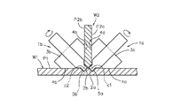
- FIG. 1B is a view in the direction of arrows AA in FIG. 1A showing a first embodiment of the friction stir welding method. It is the figure which looked at the location where the friction stir welding in the corner
- FIG. 1A and 1B show a first embodiment of the friction stir welding method
- FIG. 1A is a plan view showing a location where friction stir welding is performed at the corners of the workpieces
- FIG. 1B is A in FIG. 1A.
- the friction stir welding method of the present embodiment is formed by a first work W1 and a second work W2 that is abutted at an angular posture intersecting the surface P1 of the first work W1.
- Two corners (inner corners) c1 and c2 to be subjected to friction stir welding are used.
- the surface P1 of the first workpiece W1 is horizontally disposed
- the second workpiece W2 is abutted from above with the surface P1 of the first workpiece W1 in a vertical posture. Will be described.
- the first workpiece W1 and the second workpiece W2 are held by a workpiece holding means (not shown) in the arrangement.
- the first friction stir welding tool 1a disposed at the corner c1 on the side surface P2a side of the second workpiece W2 out of the two corners c1 and c2.
- the second friction stir welding tool 1b disposed at the corner c2 on the other side surface P2b side.
- the first friction stir welding tool 1a includes a probe 2a that can be rotated and a fixed shoulder 3a that is disposed on the outer periphery of the proximal end side of the probe 2a.
- the probe 2a is preferably arranged in an angular posture in which the axial direction is parallel to the bisector of the angle of the corner portion c1.
- the corner portion c1 is a right angle
- the axial center direction of the probe 2a is an obliquely downward angle posture inclined by 45 degrees from the vertical direction along the second workpiece W2 toward the one side surface P2a. Is set.
- the fixed shoulder 3a includes two workpieces whose end portions disposed near the tip of the probe 2a are in contact with the surface P1 of the first workpiece W1 and the side surface P2a of the second workpiece W2 that form the corner portion c1. It is a mountain shape (V shape) provided with the contact surface 4a.
- the second friction stir welding tool 1b includes a probe 2b that can be driven to rotate, and a fixed shoulder 3b disposed on the outer periphery of the proximal end side of the probe 2b.
- the probe 2b is preferably arranged in an angular posture in which the axial direction is parallel to the bisector of the angle of the corner portion c2.
- the corner portion c2 is a right angle
- the axial center direction of the probe 2b is an obliquely downward angle posture inclined by 45 degrees from the vertical direction along the second workpiece W2 to the other side surface P2b. Has been placed.
- the fixed shoulder 3b includes two workpieces whose end portions arranged near the tip of the probe 2b are in contact with the surface P1 of the first workpiece W1 and the side surface P2b of the second workpiece W2 that form the corner portion c2. It is a mountain shape (V shape) provided with the contact surface 4b.
- the first friction stir welding tool 1a and the second friction stir welding tool 1b include a region 5a in which the probe 2a is immersed in the corner c1 and agitated, and a probe 2b in the corner corner.
- the relative position is set such that the region 5b immersed in c2 and stirred is formed at a symmetrical position with the second workpiece W2 as the center.
- the fixed shoulders 3a and 3b and the probes 2a and 2b are arranged on both sides of the second workpiece W2 so that the positions thereof are aligned in the direction of friction stir welding.
- the first friction stir welding tool 1a and the second friction stir welding tool 1b perform friction stir welding of the corner corner c1 and the corner corner c2 as the second workpiece W2.
- the protruding amounts of the probes 2a and 2b from the fixed shoulders 3a and 3b are set.
- the first workpiece W1 and the second workpiece W2 are divided into the regions 5a, in which the friction stir welding of the corners c1, c2 by the friction stir welding tools 1a, 1b is stirred by the probes 2a, 2b.
- This is performed as a partial agitation joining in which 5b do not interfere with each other.
- a mutual mutual contact surface remains between the parts joined by stirring in field 5a and 5b.
- the friction stir welding tools 1a and 1b are arranged in the vicinity of the starting end positions of the friction stir welding at the corners c1 and c2.
- the location where the pressing load for immersing the probe 2a into the corner c1 acts on the workpieces W1 and W2 is the position of the region 5a.
- the location where the pressing load for immersing the probe 2b into the corner c2 acts on the workpieces W1 and W2 is the position of the region 5b.
- the probes 2a and 2b are immersed in the corners c1 and c2, and the workpiece contact surfaces 4a and 4b of the fixed shoulders 3a and 3b are moved to the workpieces W1 and W2, respectively.
- the relative movement of the friction stir welding tools 1a, 1b and the workpieces W1, W2 in the direction along the corners c1, c2 is started.
- the relative movement between the friction stir welding tools 1a and 1b and the workpieces W1 and W2 is the same as the method of moving the friction stir welding tools 1a and 1b while fixing the workpieces W1 and W2.
- each workpiece W1 and W2 are friction stir welded.
- the workpiece holding means (not shown) that holds the workpieces W1 and W2 when performing friction stir welding is used to fix the positions of the workpieces W1 and W2 against the rotational moment as described above. Rigidity and strength are not particularly required. Therefore, the structure of the work holding means can be simplified.
- the horizontal component that is the direction along the surface P1 of the first workpiece W1 of the pressing load of the probe 2a and the horizontal component of the pressing load of the probe 2b Therefore, it is possible to reduce the horizontal force acting on the workpiece holding means (not shown) that holds the workpieces W1 and W2.
- the friction stir welding tools 1a and 1b are set so that the protruding amounts of the probes 2a and 2b from the fixed shoulders 3a and 3b perform partial stir welding. Therefore, for each corner portion c1, c2, friction stir welding by simultaneous construction from both sides of the second workpiece W2 can be performed.
- the stirring is generally performed as the friction stir welding at the corners, and the entire stirring where the stirring regions by the probes arranged at the corners interfere with each other. Compared with the case of joining, the amount of insertion of each probe 2a, 2b into the corners c1, c2 can be reduced.
- the reaction force received by each probe 2a, 2b when the probe 2a, 2b is moved in a state where it is immersed in each corner c1, c2 is the reaction force received by the probe when performing all stir welding. It can be made smaller. Therefore, in the friction stir welding method according to the present embodiment, the construction speed of the friction stir welding can be increased as compared with the case where all the stir welding is performed, and the long life of each friction stir welding tool 1a, 1b is achieved. Can be achieved.
- the amount of heat that is locally input to the regions 5a and 5b in which the workpieces W1 and W2 are stirred by the frictional heat generated by the individual probes 2a and 2b is the total stir welding. It is reduced compared with the case of performing. Therefore, generation
- the friction stir welding method of the present embodiment since the friction stir welding is performed simultaneously from both sides of the second workpiece W2 at each corner c1, c2, each workpiece W1, W2 At one position in the direction of friction stir welding, heating by frictional heat generated by the probes 2a and 2b is performed. Therefore, the friction stir welding method of the present embodiment is different from the case where the corner c1 and the corner c2 are heated by friction heat generated by probes arranged at different positions in the friction stir welding traveling direction. The workpieces W1 and W2 can be heated more efficiently. Therefore, in the friction stir welding method of the present embodiment, the friction stir welding of the corner corner portion c1 and the corner corner portion c2 can be stabilized by high heat input.
- the regions 5a and 5b stirred by the probes 2a and 2b are easily softened.
- This friction stir welding method can increase the construction speed of the friction stir welding.
- the friction stir welding tools 1a and 1b can have a long life.
- the corner corner c1 and the corner corner c2 are heated by frictional heat generated by probes arranged at different positions in the X-axis direction, one of the corner corner c1 and the corner corner c2 precedes.
- the heat input to the corners c1 and c2 may not be uniform because the other is heated later. Equalization can be achieved.
- the fixed shoulders 3a and 3b of the respective friction stir welding tools 1a and 1b are directly arranged at the corners c1 and c2. Therefore, for example, when performing friction stir welding at a corner using a friction stir welding tool of the type equipped with a rotary shoulder, a triangular cross-section member is placed at the corner or a corner is placed on one workpiece. Although pre-processing such as providing a protruding portion with a triangular cross section at the corner is required, the pre-processing is not necessary in the friction stir welding method of this embodiment.
- FIG. 2 shows an application example of the first embodiment, and is a view of the part where the friction stir welding is performed at the corners of the workpieces as viewed from one of the friction stir welding advancing directions.
- FIG. 2 the same components as those shown in FIGS. 1A and 1B are denoted by the same reference numerals, and the description thereof is omitted.
- the fixed shoulders 3a and 3b in the friction stir welding tools 1a and 1b are moved along the corners c1 and c2 as the friction stir welding proceeds. At this time, the fixed shoulders 3a and 3b slide relative to the workpieces W1 and W2. Therefore, the load when pressing each fixed shoulder 3a, 3b against the corners c1, c2 may be substantially constant.
- the loads Ls1 and Ls2 when the fixed shoulders 3a and 3b are pressed against the corners c1 and c2 are controlled separately from the pressing loads Lp1 and Lp2 of the probes 2a and 2b.
- the pressing loads Lp1 and Lp2 applied to the probes 2a and 2b are appropriately controlled so that the amount of heat required for the regions 5a and 5b at the corners c1 and c2 is generated by the frictional heat of the probes 2a and 2b. What should I do? Further, the pressing loads Lp1 and Lp2 applied to the probes 2a and 2b may be controlled so that the torque required for rotational driving of the probes 2a and 2b becomes a value within a predetermined range.
- the loads Ls1 and Ls2 applied to the fixed shoulders 3a and 3b may be controlled so as to be in a certain range set in advance.
- FIGS. 1A and 1B Other configurations are the same as those shown in FIGS. 1A and 1B, and the same components are denoted by the same reference numerals.
- the first implementation It can be used in the same manner as the embodiment, and the same effects as those of the first embodiment can be obtained, such as no rotational moment is generated in the horizontal plane on the workpieces W1, W2 when the friction stir welding proceeds.
- FIG. 3 shows a second embodiment of the friction stir welding method, and is a view of the part where the friction stir welding is performed at the corners of the workpieces as viewed from one side in the direction of friction stir welding.
- FIG. 3 the same components as those shown in FIGS. 1A and 1B are denoted by the same reference numerals, and the description thereof is omitted.
- the friction stir welding method includes two corners (inner parts) formed by a first workpiece W1 and a second workpiece W2 that is abutted with respect to the surface P1 at an angle other than 90 degrees. Corners c1 and c2 are to be subjected to friction stir welding.
- the surface P1 of the first workpiece W1 is arranged along the horizontal plane, and the second workpiece W2 is tilted at an angle from the vertical surface to the side surface P2b. The case where it is faced
- the friction stir welding tools 1a and 1b used in the friction stir welding method of the present embodiment have the same configuration as that of the first embodiment, and the fixed shoulder 3a of the first friction stir welding tool 1a disposed at the corner c1. Is a configuration including an obtuse angle-shaped end portion formed by the surface P1 of the first workpiece W1 and the side surface P2a of the second workpiece W2.
- the probe 2a of the first friction stir welding tool 1a is arranged in an angular posture in which the axial direction is parallel to the bisector of the angle of the corner portion c1.
- the fixed shoulder 3b of the second friction stir welding tool 1b arranged at the corner c2 is an acute angle chevron formed by the surface P1 of the first workpiece W1 and the side surface P2b of the second workpiece W2. It is the structure provided with the edge part.
- the probe 2b of the second friction stir welding tool 1b is arranged in an angular posture in which the axial center direction is parallel to the bisector of the angle of the corner portion c2.
- FIGS. 1A and 1B Other configurations are the same as those shown in FIGS. 1A and 1B, and the same components are denoted by the same reference numerals.
- Friction stir welding of the two corner portions c1 and c2 can be performed.
- Each friction stir welding tool 1a, 1b is the corner
- each friction stir welding tool 1a, 1b the axial center direction of each probe 2a, 2b may be inclined in the traveling direction of the friction stir welding.
- each of the fixed shoulders 3a and 3b has a mountain shape on the workpiece contact surfaces 4a and 4b to be brought into contact with the surfaces of the workpieces W1 and W2 on both sides of the corners c1 and c2 to be joined, the other portions are illustrated. Other shapes may be used.
- the plane on which the surface P1 of the first workpiece W1 is arranged is not a horizontal plane and may be inclined. In this case, what is necessary is just to set the angle attitude
- Non-Patent Document 1 When performing friction stir welding, a method called AdStir shown in Non-Patent Document 1 may be applied.
- each friction stir welding tool 1a, 1b is formed in a mountain shape formed by the work contact surfaces 4a, 4b of the fixed shoulders 3a, 3b in the same configuration as shown in FIG. 1A, FIG. 1B or FIG.
- the front part of the friction stir welding direction is provided with a notch for inserting a weld filler, and the rear side of the friction stir welding direction is in accordance with the fillet desired to be formed at the corners c1 and c2 after joining. What is necessary is just to set it as the structure provided with the notch part of the shape.
Landscapes
- Engineering & Computer Science (AREA)
- Mechanical Engineering (AREA)
- Pressure Welding/Diffusion-Bonding (AREA)
Abstract
本開示は、プローブ(2a,2b)と、固定式ショルダ(3a,3b)とを備えた一対の摩擦撹拌接合ツール(1a,1b)を、第1のワーク(W1)と第2のワーク(W2)との間の角隅部(c1,c2)に配置する。この際、摩擦撹拌接合ツール(1a,1b)は、各プローブ(2a,2b)が各角隅部(c1,c2)に没入されて撹拌される領域(5a,5b)が、第2のワーク(W2)を中心とした対称位置に形成されるように配置する。この配置とした各摩擦撹拌接合ツール(1a,1b)により、各角隅部(c1,c2)を同時に摩擦撹拌接合させる。
Description
本開示は、ワーク同士の角隅部の接合に用いる摩擦撹拌接合方法に関する。
本願は、2015年1月9日に、日本に出願された特願2015-3000号に基づき優先権を主張し、その内容をここに援用する。
本願は、2015年1月9日に、日本に出願された特願2015-3000号に基づき優先権を主張し、その内容をここに援用する。
摩擦撹拌接合を実施する場合に使用される摩擦撹拌接合ツール(摩擦撹拌接合用工具)としては、プローブと一体に回転する回転式ショルダを備えた形式と、回転するプローブと非回転の固定式ショルダとを備えた形式が知られている。
固定式ショルダを備える摩擦撹拌接合ツールとしては、接合すべきワーク同士の角隅部(内隅部)を摩擦撹拌接合するために、固定式ショルダが角隅部の両ワーク表面に当接する面を備える形状が知られている。
更に、前記のような角隅部接合用の摩擦撹拌接合ツールを2個用いて、水平なワーク(水平部材)と、その上に立設されるワーク(立設部材)との突き合わせによって形成された2つの角隅部を、立設されるワークの両側から摩擦撹拌接合する手法が、従来提案されている(たとえば、特許文献1参照)。
この摩擦撹拌接合手法では、立設されるワークの両側に配置される摩擦撹拌接合用工具(摩擦撹拌接合ツール)を、撹拌軸(プローブ)同士の摩擦撹拌接合進行方向の位置をずらした構成とすることで、撹拌軸同士の衝突や、撹拌領域の相互干渉による接合の乱れを防ぐ。
又、固定式ショルダを備えた摩擦撹拌接合ツールによる角隅部の摩擦撹拌接合を行う際に、溶接フィラーを加えて、接合後の角隅部にR(肉盛りによるフィレット)を形成させるようにしたAdStirと云われる手法も、従来提案されている(たとえば、非特許文献1参照)。
福田哲夫,角張隆男、「TWIの最新FSWプロセス開発状況とパテント情報」、溶接技術、産報出版株式会社、2011年6月、59巻、6号、p.57-60
ところが、特許文献1に示された摩擦撹拌接合手法では、立設するワークの両側に配置される摩擦撹拌接合ツールの撹拌軸の位置が、摩擦撹拌接合進行方向にずれている。そのため、摩擦撹拌接合の開始時に撹拌軸を各角隅部に没入させるときには、各ワークや、各ワークを保持している手段に対し、水平面内で回転モーメントが発生する。
なお、非特許文献1には、摩擦撹拌接合時にワークに生じる回転モーメントを防止する考えは特に示されていない。
そこで、本開示は、固定式ショルダを備えた一対の摩擦撹拌接合ツールを用いてワーク同士の2つの角隅部の摩擦撹拌接合を行う場合に、各ワークに、一方のワークに沿う面内での回転モーメントが生じないようにすることができる摩擦撹拌接合方法を提供する。
本開示の第1の態様は、第1のワークと、前記第1のワークの面に対して交わる角度姿勢で端縁を接して配置される第2のワークとで形成される両角隅部を接合する摩擦撹拌接合方法であって、前記両角隅部に回転駆動して没入させるプローブと、前記プローブの基端側の外周に配置されて前記各角隅部を形成する2つのワークの面に接触させられる固定式ショルダとを有する一対の摩擦撹拌接合ツールを、前記第2のワークを挟んだ両側の角隅部に配置して、前記各プローブが前記各角隅部に没入されて撹拌される領域が前記第2のワークを中心とした対称位置に形成されるようにし、前記各摩擦撹拌接合ツールにより各角隅部を同時に摩擦撹拌接合する摩擦撹拌接合方法である。
本開示の摩擦撹拌接合方法によれば、固定式ショルダを備えた一対の摩擦撹拌接合ツールを用いてワーク同士の2つの角隅部の摩擦撹拌接合を行う場合に、各ワークに、一方のワークに沿う面内での回転モーメントが生じないようにすることができる。
本開示の摩擦撹拌接合方法について、図面を参照して説明する。
[第1実施形態]
図1A及び図1Bは、摩擦撹拌接合方法の第1実施形態を示し、図1Aはワーク同士の角隅部における摩擦撹拌接合が行われている個所を示す平面図、図1Bは図1AのA-A方向矢視図である。
図1A及び図1Bは、摩擦撹拌接合方法の第1実施形態を示し、図1Aはワーク同士の角隅部における摩擦撹拌接合が行われている個所を示す平面図、図1Bは図1AのA-A方向矢視図である。
本実施形態の摩擦撹拌接合方法は、図1Bに示すように、第1のワークW1と、第1のワークW1の面P1に対し交差する角度姿勢で突き合わされた第2のワークW2とにより形成される2つの角隅部(内隅部)c1,c2を、摩擦撹拌接合の対象である。本実施形態では、一例として、第1のワークW1の面P1が水平に配置され、第2のワークW2が鉛直な姿勢で第1のワークW1の面P1に対して上方から突き合わされている場合について説明する。なお、第1のワークW1と第2のワークW2は、前記配置とされた状態で図示しないワーク保持手段により保持されている。
本実施形態の摩擦撹拌接合方法には、2つの角隅部c1,c2のうち、第2のワークW2の一方の側面P2a側の角隅部c1に配置される第1の摩擦撹拌接合ツール1aと、他方の側面P2b側の角隅部c2に配置される第2の摩擦撹拌接合ツール1bとが用いられる。
第1の摩擦撹拌接合ツール1aは、回転駆動可能なプローブ2aと、プローブ2aの基端側の外周に配置された固定式ショルダ3aとを備えた構成である。プローブ2aは、軸心方向が角隅部c1の角度の二等分線に平行となる角度姿勢に配置されていることが好ましい。本実施形態では、角隅部c1が直角であるため、プローブ2aの軸心方向は、第2のワークW2に沿う鉛直方向から一方の側面P2a側へ45度傾斜させた斜め下向きの角度姿勢に設定されている。固定式ショルダ3aは、プローブ2aの先端寄りに配置される端部が、角隅部c1を形成させる第1のワークW1の面P1と第2のワークW2の側面P2aとに接触させる2つのワーク接触面4aを備えた山形(V字形状)である。
第2の摩擦撹拌接合ツール1bは、回転駆動可能なプローブ2bと、プローブ2bの基端側の外周に配置された固定式ショルダ3bとを備えた構成である。プローブ2bは、軸心方向が角隅部c2の角度の二等分線に平行となる角度姿勢に配置されていることが好ましい。本実施形態では、角隅部c2が直角であるため、プローブ2bの軸心方向は、第2のワークW2に沿う鉛直方向から他方の側面P2b側へ45度傾斜させた斜め下向きの角度姿勢に配置されている。固定式ショルダ3bは、プローブ2bの先端寄りに配置される端部が、角隅部c2を形成させる第1のワークW1の面P1と第2のワークW2の側面P2bとに接触させる2つのワーク接触面4bを備えた山形(V字形状)である。
第1の摩擦撹拌接合ツール1aと第2の摩擦撹拌接合ツール1bは、図1Aに示すように、プローブ2aが角隅部c1に没入されて撹拌される領域5aと、プローブ2bが角隅部c2に没入されて撹拌される領域5bとが、第2のワークW2を中心とした対称位置に形成されるように、相対位置が設定されている。具体的には、固定式ショルダ3a,3b同士、及び、プローブ2a,2b同士が、第2のワークW2の両側に、摩擦撹拌接合進行方向に位置を揃えて配置されている。
又、第1の摩擦撹拌接合ツール1aと第2の摩擦撹拌接合ツール1bは、図1A及び図1Bに示すように、角隅部c1と角隅部c2の摩擦撹拌接合を第2のワークW2の両面側で同時に行うときに、各角隅部c1,c2に没入させるプローブ2a,2b同士、更には、各プローブ2a,2bによりそれぞれ撹拌される領域5a,5b同士に干渉が生じないように、プローブ2a,2bの固定式ショルダ3a,3bからの突出量が設定されている。
これにより、第1のワークW1と第2のワークW2は、各摩擦撹拌接合ツール1a,1bによる各角隅部c1,c2の摩擦撹拌接合が、各プローブ2a,2bにより撹拌される領域5a,5b同士が互いに干渉しない部分撹拌接合として行われる。このため、接合後の第1のワークW1と第2のワークW2では、領域5a,5bでの撹拌によって接合された部分同士の間に、互いの当接面が一部残っている。
本実施形態の摩擦撹拌接合方法を実施する場合は、先ず、各摩擦撹拌接合ツール1a,1bを、各角隅部c1,c2における摩擦撹拌接合の始端位置の近傍に配置させる。
次に、各摩擦撹拌接合ツール1a,1bでは、それぞれのプローブ2a,2bの回転駆動を開始させた後、プローブ2a,2bを各角隅部c1,c2に没入させる。
この際、プローブ2aを角隅部c1へ没入させるための押圧荷重が各ワークW1,W2に対して作用する個所は、領域5aの位置である。一方、プローブ2bを角隅部c2へ没入させるための押圧荷重が各ワークW1,W2に対して作用する個所は、領域5bの位置である。
このため、各プローブ2a,2bを各角隅部c1,c2に没入させる過程では、各ワークW1,W2にプローブ2aの押圧荷重が作用する個所と、プローブ2bの押圧荷重が作用する個所が、第2のワークW2を中心とした対称位置となるので、各ワークW1,W2に、各押圧荷重に起因して第1のワークW1の面P1に沿う水平面内で回転モーメントが生じることはない。
次に、本実施形態の摩擦撹拌接合方法では、各プローブ2a,2bが各角隅部c1,c2に没入されて、各固定式ショルダ3a,3bのワーク接触面4a,4bが各ワークW1,W2に接触すると、各摩擦撹拌接合ツール1a,1bと各ワークW1,W2との各角隅部c1,c2に沿う方向への相対移動を開始する。
この際、前述の各摩擦撹拌接合ツール1a,1bと各ワークW1,W2との相対移動は、各ワークW1,W2を固定して各摩擦撹拌接合ツール1a,1bを移動させる手法と、位置が固定された各摩擦撹拌接合ツール1a,1bに対して各ワークW1,W2を移動させる手法のいずれで実施してもよい。
これにより、各角隅部c1,c2では、プローブ2a,2bにより撹拌された領域5a,5bが互いに干渉しない状態のまま摩擦撹拌接合が進行する。これにより、第1のワークW1と第2のワークW2は部分撹拌接合される。
この摩擦撹拌接合が進行する間も、各ワークW1,W2にプローブ2aの押圧荷重が作用する個所と、プローブ2bの押圧荷重が作用する個所は、第2のワークW2を中心とした対称位置の領域5aと領域5bであるため、各ワークW1,W2に、各押圧荷重に起因して第1のワークW1の面P1に沿う水平面内で回転モーメントが生じることはない。
本実施形態の摩擦撹拌接合方法では、各プローブ2a,2bが各角隅部c1,c2の摩擦撹拌接合の終端位置に達すると、各摩擦撹拌接合ツール1a,1bの各角隅部c1,c2に対する相対移動を停止する。次いで、各プローブ2a,2bは各角隅部c1,c2から抜き出し、その後、回転駆動を停止する。この各プローブ2a,2bを各角隅部c1,c2から抜き出す操作によっても、各ワークW1,W2については、前記と同様の回転モーメントが生じることはない。
以上により、各ワークW1,W2は、各角隅部c1,c2が摩擦撹拌接合される。
このように、本実施形態の摩擦撹拌接合方法によれば、固定式ショルダ3a,3bを備えた一対の摩擦撹拌接合ツール1a,1bを用いて各ワークW1,W2同士の2つの角隅部c1,c2の摩擦撹拌接合を行う場合に、各ワークW1,W2に、第1のワークW1の面P1に沿う水平面内での回転モーメントが生じることを防止することができる。
このため、摩擦撹拌接合を行うときに各ワークW1,W2の保持を行わせる図示しないワーク保持手段には、前記のような回転モーメントに抗して各ワークW1,W2の位置を固定するための剛性や強度は特に必要とされない。よって、ワーク保持手段の構造の簡略化を図ることが可能になる。
更に、各摩擦撹拌接合ツール1a,1bの前記配置では、プローブ2aの押圧荷重の第1のワークW1の面P1に沿う方向である水平方向の成分と、プローブ2bの押圧荷重の水平方向の成分とが対向するため、各ワークW1,W2の保持を行わせる図示しないワーク保持手段に作用する水平方向の力を低減させることが可能になる。
又、各摩擦撹拌接合ツール1a,1bは、固定式ショルダ3a,3bからのプローブ2a,2bの突出量が、部分撹拌接合を行うように設定されている。そのため、各角隅部c1,c2については、第2のワークW2の両面側からの同時施工による摩擦撹拌接合を実施できる。
更に、本実施形態の摩擦撹拌接合方法では、従来、角隅部の摩擦撹拌接合として一般的に行われている、各角隅部に配置されるプローブによる撹拌領域同士が相互に干渉する全撹拌接合を行う場合に比して、各プローブ2a,2bの角隅部c1,c2への挿入量を低減させることができる。
これにより、各プローブ2a,2bを各角隅部c1,c2に没入させた状態で移動させるときに各プローブ2a,2bが受ける反力は、全撹拌接合を行う場合にプローブが受ける反力に比して小さくすることができる。そのため、本実施形態の摩擦撹拌接合方法では、全撹拌接合を行う場合に比して、摩擦撹拌接合の施工速度の高速化を図ることができると共に、各摩擦撹拌接合ツール1a,1bの長寿命化を図ることができる。
更に、本実施形態の摩擦撹拌接合方法では、個々のプローブ2a,2bで発生させる摩擦熱によって各ワークW1,W2が撹拌される領域5a,5bに局所的に入熱される熱量は、全撹拌接合を行う場合に比して軽減される。そのため、ワークW1,W2の熱によるひずみや変形については、その発生を抑制することができる。
又、本実施形態の摩擦撹拌接合方法では、各角隅部c1,c2について、第2のワークW2の両面側から摩擦撹拌接合の同時施工を行うようにしてあるため、各ワークW1,W2は、摩擦撹拌接合進行方向の一つの位置では、各プローブ2a,2bで発生させる摩擦熱による加熱が行われる。そのため、本実施形態の摩擦撹拌接合方法は、角隅部c1と角隅部c2を摩擦撹拌接合進行方向の異なる位置に配置されたプローブで発生させる摩擦熱により加熱する場合に比して、各ワークW1,W2の加熱をより効率よく行うことができる。したがって、本実施形態の摩擦撹拌接合方法では、角隅部c1と角隅部c2との摩擦撹拌接合について、高入熱による摩擦撹拌接合の安定化を図ることができる。
更に、前記のように各ワークW1,W2の加熱の効率が向上することに伴い、各プローブ2a,2bにより撹拌される領域5a,5bは軟化しやすくなるので、このことによっても、本実施形態の摩擦撹拌接合方法は、摩擦撹拌接合の施工速度の高速化を図ることができる。又、各プローブ2a,2bを回転駆動させる際の抵抗が軽減されるので、各摩擦撹拌接合ツール1a,1bは、長寿命化を図ることができる。
更に、角隅部c1と角隅部c2をX軸方向の異なる位置に配置されたプローブで発生させる摩擦熱により加熱する場合は、角隅部c1と角隅部c2のいずれか一方が先行して加熱され、他方が後から加熱されることになるため、入熱の条件が均等にならない場合が生じるが、本実施形態の摩擦撹拌接合方法では、各角隅部c1,c2に対する入熱の均等化を図ることができる。
又、本実施形態の摩擦撹拌接合方法は、各摩擦撹拌接合ツール1a,1bの各固定式ショルダ3a,3bを、各角隅部c1,c2に直接配置させるようにしてある。そのため、たとえば、回転式ショルダを備えた形式の摩擦撹拌接合ツールを用いて角隅部の摩擦撹拌接合を行うときには、角隅部に三角断面の部材を配置するか、あるいは、一方のワークに角隅部に三角断面で張り出す部分を設けるというような事前処理が必要とされるが、本実施形態の摩擦撹拌接合方法では、これらの事前処理は不要である。
[第1実施形態の応用例]
図2は、第1実施形態の応用例を示すもので、ワーク同士の角隅部における摩擦撹拌接合が行われている個所を摩擦撹拌接合進行方向の一方から見た図である。
図2は、第1実施形態の応用例を示すもので、ワーク同士の角隅部における摩擦撹拌接合が行われている個所を摩擦撹拌接合進行方向の一方から見た図である。
なお、図2において、図1A及び図1Bに示したものと同一のものには同一の符号を付してその説明を省略する。
各摩擦撹拌接合ツール1a,1bにおける固定式ショルダ3a,3bは、摩擦撹拌接合の進行に伴って角隅部c1,c2に沿わせて移動させる。このとき、各固定式ショルダ3a,3bは、各ワークW1,W2に対して摺動する。そのため、各固定式ショルダ3a,3bを角隅部c1,c2に押し当てるときの荷重はほぼ一定でよい。
そこで、本応用例では、各固定式ショルダ3a,3bを角隅部c1,c2に押し当てるときの荷重Ls1,Ls2を、各プローブ2a,2bの押圧荷重Lp1,Lp2とは別に制御する。
各プローブ2a,2bに作用させる押圧荷重Lp1,Lp2は、各角隅部c1、c2における各領域5a,5bで必要とされる熱量が各プローブ2a,2bの摩擦熱で生じるように適宜制御するようにすればよい。又、各プローブ2a,2bに作用させる押圧荷重Lp1,Lp2は、各プローブ2a,2bの回転駆動に要するトルクが予め設定された或る範囲の値となるように制御してもよい。
一方、各固定式ショルダ3a,3bに作用させる荷重Ls1、Ls2は、予め別途設定された或る範囲の値となるように制御すればよい。
その他の構成は図1A及び図1Bに示したものと同様であり、同一のものには同一の符号が付してある。
本応用例のように、固定式ショルダ3a,3bに作用させる荷重Ls1,Ls2を、各プローブ2a,2bに作用させる押圧荷重Lp1,Lp2とは独立に制御する場合であっても、第1実施形態と同様に使用することができて、摩擦撹拌接合の進行時に各ワークW1,W2に水平面内で回転モーメントは発生しない等、第1実施形態と同様の効果を得ることができる。
これに対し、たとえば、特許文献1に示されたものについて、前記と同様に、固定式ショルダに作用させる荷重を、各撹拌軸(プローブ)に作用させる押圧荷重とは独立に制御する手法を適用した場合は、摩擦撹拌接合の進行時に、ワークに各撹拌軸から摩擦撹拌接合進行方向の異なる位置で押圧荷重が作用するようになる。このため、特許文献1に示されたものでは、ワークに水平面内で回転モーメントが発生してしまうが、本応用例では、このような回転モーメントの発生は防止できる。
[第2実施形態]
図3は、摩擦撹拌接合方法の第2実施形態を示すもので、ワーク同士の角隅部における摩擦撹拌接合が行われている個所を摩擦撹拌接合進行方向の一方から見た図である。
図3は、摩擦撹拌接合方法の第2実施形態を示すもので、ワーク同士の角隅部における摩擦撹拌接合が行われている個所を摩擦撹拌接合進行方向の一方から見た図である。
なお、図3において、図1A及び図1Bに示したものと同一のものには同一の符号を付してその説明を省略する。
本実施形態の摩擦撹拌接合方法は、第1のワークW1と、その面P1に対して90度以外の角度姿勢で突き合わされた第2のワークW2とにより形成される2つの角隅部(内隅部)c1,c2を、摩擦撹拌接合の対象とする。本実施形態では、一例として、第1のワークW1の面P1が水平面に沿って配置され、第2のワークW2が鉛直面から側面P2b側へ或る角度傾いた角度姿勢で第1のワークW1の面P1に対して上方から突き合わされている場合について説明する。したがって、一方の角隅部c1は鈍角になっており、他方の角隅部c2は鋭角になっている。
本実施形態の摩擦撹拌接合方法で用いる摩擦撹拌接合ツール1a,1bは、第1実施形態と同様な構成において、角隅部c1に配置される第1の摩擦撹拌接合ツール1aの固定式ショルダ3aが、第1のワークW1の面P1と第2のワークW2の側面P2aとにより形成された鈍角の山形の端部を備えた構成である。
第1の摩擦撹拌接合ツール1aのプローブ2aは、軸心方向が角隅部c1の角度の二等分線に平行となる角度姿勢に配置されている。
又、角隅部c2に配置される第2の摩擦撹拌接合ツール1bの固定式ショルダ3bは、第1のワークW1の面P1と第2のワークW2の側面P2bとにより形成された鋭角の山形の端部を備えた構成である。
第2の摩擦撹拌接合ツール1bのプローブ2bは、軸心方向が角隅部c2の角度の二等分線に平行となる角度姿勢に配置されている。
その他の構成は図1A及び図1Bに示したものと同様であり、同一のものには同一の符号が付してある。
本実施形態の摩擦撹拌接合方法によれば、第1実施形態と同様に使用することにより、第1のワークW1と、90度以外の角度姿勢で突き合わされた第2のワークW2との間の2つの角隅部c1,c2の摩擦撹拌接合を行うことができる。
この際、摩擦撹拌接合の進行時に各ワークW1,W2に水平面内で回転モーメントは発生しないという、第1実施形態と同様の効果を得ることができる。
なお、本開示は、前記各実施形態、応用例にのみ限定されるものではなく、各摩擦撹拌接合ツール1a,1bは、各プローブ2a,2bの軸心方向が、それぞれ接合対象となる角隅部c1,c2の角度の二等分線の方向に必ずしも一致していなくてもよい。
各摩擦撹拌接合ツール1a,1bは、各プローブ2a,2bの軸心方向が、摩擦撹拌接合の進行方向に傾斜していてもよい。
各固定式ショルダ3a,3bは、接合対象の角隅部c1,c2の両側の各ワークW1,W2の面に接触させるワーク接触面4a,4bが山形となっていれば、その他の部分は図示した以外の形状としてもよい。
第1のワークW1の面P1を配置する平面は水平面でなく、傾斜していてもよい。この場合は、各摩擦撹拌接合ツール1a,1bの角度姿勢を、各角隅部c1,c2に合わせて設定すればよい。
摩擦撹拌接合を行うときに、非特許文献1に示されたAdStirと云われる手法を適用してもよい。
この場合は、各摩擦撹拌接合ツール1a,1bを、図1A及び図1B又は図2に示したと同様の構成において、各固定式ショルダ3a,3bのワーク接触面4a,4bにより形成されている山形の頂部に、摩擦撹拌接合進行方向の前側では溶接フィラーを挿入するための切欠部を備え、摩擦撹拌接合進行方向の後側では接合後の角隅部c1,c2に形成を所望するフィレットに応じた形状の切欠部を備えた構成とすればよい。
その他本開示の要旨を逸脱しない範囲内で種々変更を加え得ることは勿論である。
本開示によれば、ワークに摩擦撹拌接合ツールの押圧荷重による回転モーメントが生じないようにすることができる。
1a 第1の摩擦撹拌接合ツール(摩擦撹拌接合ツール)
1b 第2の摩擦撹拌接合ツール(摩擦撹拌接合ツール)
2a,2b プローブ
3a,3b 固定式ショルダ
5a,5b 領域
W1 第1のワーク
W2 第2のワーク
c1,c2 角隅部
1b 第2の摩擦撹拌接合ツール(摩擦撹拌接合ツール)
2a,2b プローブ
3a,3b 固定式ショルダ
5a,5b 領域
W1 第1のワーク
W2 第2のワーク
c1,c2 角隅部
Claims (2)
- 第1のワークと、前記第1のワークの面に対して交わる角度姿勢で端縁を接して配置される第2のワークとで形成される両角隅部を接合する摩擦撹拌接合方法であって、
前記両角隅部に回転駆動して没入させるプローブと、前記プローブの基端側の外周に配置されて前記各角隅部を形成する2つのワークの面に接触させられる固定式ショルダとを有する一対の摩擦撹拌接合ツールを、前記第2のワークを挟んだ両側の角隅部に配置して、前記各プローブが前記各角隅部に没入されて撹拌される領域が前記第2のワークを中心とした対称位置に形成されるようにし、
前記各摩擦撹拌接合ツールにより各角隅部を同時に摩擦撹拌接合する摩擦撹拌接合方法。 - 前記各摩擦撹拌接合ツールは、前記各プローブが前記各角隅部に没入されて撹拌される領域が干渉しないように配置されている請求項1記載の摩擦撹拌接合方法。
Priority Applications (3)
| Application Number | Priority Date | Filing Date | Title |
|---|---|---|---|
| CN201680005052.5A CN107107256A (zh) | 2015-01-09 | 2016-01-05 | 摩擦搅拌接合方法 |
| KR1020177020871A KR20170098312A (ko) | 2015-01-09 | 2016-01-05 | 마찰 교반 접합 방법 |
| US15/642,013 US20170297142A1 (en) | 2015-01-09 | 2017-07-05 | Friction stir welding method |
Applications Claiming Priority (2)
| Application Number | Priority Date | Filing Date | Title |
|---|---|---|---|
| JP2015-003000 | 2015-01-09 | ||
| JP2015003000A JP2016128178A (ja) | 2015-01-09 | 2015-01-09 | 摩擦撹拌接合方法 |
Related Child Applications (1)
| Application Number | Title | Priority Date | Filing Date |
|---|---|---|---|
| US15/642,013 Continuation US20170297142A1 (en) | 2015-01-09 | 2017-07-05 | Friction stir welding method |
Publications (1)
| Publication Number | Publication Date |
|---|---|
| WO2016111279A1 true WO2016111279A1 (ja) | 2016-07-14 |
Family
ID=56355967
Family Applications (1)
| Application Number | Title | Priority Date | Filing Date |
|---|---|---|---|
| PCT/JP2016/050090 Ceased WO2016111279A1 (ja) | 2015-01-09 | 2016-01-05 | 摩擦撹拌接合方法 |
Country Status (5)
| Country | Link |
|---|---|
| US (1) | US20170297142A1 (ja) |
| JP (1) | JP2016128178A (ja) |
| KR (1) | KR20170098312A (ja) |
| CN (1) | CN107107256A (ja) |
| WO (1) | WO2016111279A1 (ja) |
Cited By (7)
| Publication number | Priority date | Publication date | Assignee | Title |
|---|---|---|---|---|
| US9987707B2 (en) * | 2016-08-16 | 2018-06-05 | Xiao Dong | 3D print apparatus and method utilizing friction stir welding |
| US20240326156A1 (en) * | 2023-03-30 | 2024-10-03 | Blue Origin, Llc | Deposition head for friction stir additive manufacturing devices and methods |
| US12303994B2 (en) | 2023-08-03 | 2025-05-20 | Blue Origin Manufacturing, LLC | Friction stir additive manufacturing formed parts and structures with integrated passages |
| US12383975B2 (en) | 2023-08-03 | 2025-08-12 | Blue Origin Manufacturing, LLC | Friction stir additive manufacturing formed parts and structures with integrated passages |
| US12415229B2 (en) | 2020-07-29 | 2025-09-16 | Blue Origin Manufacturing, LLC | Friction stir welding systems and methods |
| US12558739B2 (en) | 2023-03-30 | 2026-02-24 | Blue Origin Manufacturing, LLC | Friction stir additive manufacturing devices and methods for forming in-situ rivets |
| US12589446B2 (en) | 2023-12-12 | 2026-03-31 | Blue Origin Manufacturing, LLC | Wire-feed friction stir additive manufacturing systems, devices, and methods |
Families Citing this family (5)
| Publication number | Priority date | Publication date | Assignee | Title |
|---|---|---|---|---|
| JP2014094409A (ja) * | 2012-10-10 | 2014-05-22 | Nippon Light Metal Co Ltd | 伝熱板の製造方法及び摩擦攪拌接合方法 |
| JP2019025490A (ja) * | 2017-07-25 | 2019-02-21 | 日本軽金属株式会社 | 接合方法 |
| JP6770014B2 (ja) * | 2018-03-19 | 2020-10-14 | Primetals Technologies Japan株式会社 | 摩擦攪拌接合装置用アイロニングプレートとそれを備えた摩擦攪拌接合装置、ならびに摩擦攪拌接合方法 |
| GB2593271A (en) * | 2020-01-14 | 2021-09-22 | Bae Systems Plc | Friction stir welding process |
| CN116275463B (zh) * | 2023-05-25 | 2023-08-11 | 合肥工业大学 | 一种适用于角接接头的轴肩角度可调型搅拌摩擦焊搅拌头 |
Citations (5)
| Publication number | Priority date | Publication date | Assignee | Title |
|---|---|---|---|---|
| JP2001321965A (ja) * | 2000-05-19 | 2001-11-20 | Nissho Iwai Hitetsu Hanbai Kk | 摩擦撹拌接合によるすみ接合法 |
| JP2003326375A (ja) * | 2002-05-14 | 2003-11-18 | Mitsubishi Heavy Ind Ltd | 垂直若しくは傾斜立設継手構造体 |
| JP2011079031A (ja) * | 2009-10-09 | 2011-04-21 | Nippon Light Metal Co Ltd | 内隅接合用回転ツール及びこれを用いた内隅接合方法 |
| JP2013166159A (ja) * | 2012-02-14 | 2013-08-29 | Mitsubishi Heavy Ind Ltd | 摩擦撹拌接合装置 |
| JP2013202630A (ja) * | 2012-03-27 | 2013-10-07 | Ihi Corp | 摩擦撹拌接合装置 |
Family Cites Families (11)
| Publication number | Priority date | Publication date | Assignee | Title |
|---|---|---|---|---|
| DE19938100A1 (de) * | 1999-08-12 | 2001-02-15 | Exama Maschinen Gmbh | Mehrkopf-Reibschweißverfahren |
| NO995093D0 (no) * | 1999-10-19 | 1999-10-19 | Norsk Hydro As | Fremgangsmåte og anordning for punktsveising |
| US6758382B1 (en) * | 2003-05-02 | 2004-07-06 | The United States Of America As Represented By The Administrator Of The National Aeronautics And Space Administration | Auto-adjustable tool for self-reacting and conventional friction stir welding |
| US20050045695A1 (en) * | 2003-08-29 | 2005-03-03 | Subramanian Pazhayannur Ramanathan | Apparatus and method for friction stir welding using a consumable pin tool |
| US20110206786A1 (en) * | 2010-02-23 | 2011-08-25 | Brett Justin West | Acai and Iridoid Based Formulations |
| EP2711910A1 (en) * | 2011-05-18 | 2014-03-26 | Nissan Motor Co., Ltd | Driving instablity determination device |
| KR20170002686A (ko) * | 2011-08-19 | 2017-01-06 | 니폰게이긴조쿠가부시키가이샤 | 마찰 교반 접합 방법 |
| JP5987397B2 (ja) * | 2012-03-27 | 2016-09-07 | 株式会社Ihi | 摩擦撹拌接合装置 |
| JP6224993B2 (ja) * | 2013-11-01 | 2017-11-01 | 川崎重工業株式会社 | 摩擦攪拌接合装置 |
| US9010613B1 (en) * | 2013-12-16 | 2015-04-21 | The Boeing Company | Apparatus for friction stir welding |
| US8857696B1 (en) * | 2014-04-01 | 2014-10-14 | King Fahd University Of Petroleum And Minerals | Method and tool for friction stir welding |
-
2015
- 2015-01-09 JP JP2015003000A patent/JP2016128178A/ja active Pending
-
2016
- 2016-01-05 KR KR1020177020871A patent/KR20170098312A/ko not_active Ceased
- 2016-01-05 CN CN201680005052.5A patent/CN107107256A/zh active Pending
- 2016-01-05 WO PCT/JP2016/050090 patent/WO2016111279A1/ja not_active Ceased
-
2017
- 2017-07-05 US US15/642,013 patent/US20170297142A1/en not_active Abandoned
Patent Citations (5)
| Publication number | Priority date | Publication date | Assignee | Title |
|---|---|---|---|---|
| JP2001321965A (ja) * | 2000-05-19 | 2001-11-20 | Nissho Iwai Hitetsu Hanbai Kk | 摩擦撹拌接合によるすみ接合法 |
| JP2003326375A (ja) * | 2002-05-14 | 2003-11-18 | Mitsubishi Heavy Ind Ltd | 垂直若しくは傾斜立設継手構造体 |
| JP2011079031A (ja) * | 2009-10-09 | 2011-04-21 | Nippon Light Metal Co Ltd | 内隅接合用回転ツール及びこれを用いた内隅接合方法 |
| JP2013166159A (ja) * | 2012-02-14 | 2013-08-29 | Mitsubishi Heavy Ind Ltd | 摩擦撹拌接合装置 |
| JP2013202630A (ja) * | 2012-03-27 | 2013-10-07 | Ihi Corp | 摩擦撹拌接合装置 |
Cited By (8)
| Publication number | Priority date | Publication date | Assignee | Title |
|---|---|---|---|---|
| US9987707B2 (en) * | 2016-08-16 | 2018-06-05 | Xiao Dong | 3D print apparatus and method utilizing friction stir welding |
| US12415229B2 (en) | 2020-07-29 | 2025-09-16 | Blue Origin Manufacturing, LLC | Friction stir welding systems and methods |
| US20240326156A1 (en) * | 2023-03-30 | 2024-10-03 | Blue Origin, Llc | Deposition head for friction stir additive manufacturing devices and methods |
| US12246392B2 (en) * | 2023-03-30 | 2025-03-11 | Blue Origin Manufacturing, LLC | Deposition head for friction stir additive manufacturing devices and methods |
| US12558739B2 (en) | 2023-03-30 | 2026-02-24 | Blue Origin Manufacturing, LLC | Friction stir additive manufacturing devices and methods for forming in-situ rivets |
| US12303994B2 (en) | 2023-08-03 | 2025-05-20 | Blue Origin Manufacturing, LLC | Friction stir additive manufacturing formed parts and structures with integrated passages |
| US12383975B2 (en) | 2023-08-03 | 2025-08-12 | Blue Origin Manufacturing, LLC | Friction stir additive manufacturing formed parts and structures with integrated passages |
| US12589446B2 (en) | 2023-12-12 | 2026-03-31 | Blue Origin Manufacturing, LLC | Wire-feed friction stir additive manufacturing systems, devices, and methods |
Also Published As
| Publication number | Publication date |
|---|---|
| US20170297142A1 (en) | 2017-10-19 |
| CN107107256A (zh) | 2017-08-29 |
| JP2016128178A (ja) | 2016-07-14 |
| KR20170098312A (ko) | 2017-08-29 |
Similar Documents
| Publication | Publication Date | Title |
|---|---|---|
| WO2016111279A1 (ja) | 摩擦撹拌接合方法 | |
| US20140360650A1 (en) | Friction Stir Processing Tool Having Non-Circumferential Shoulder and Friction Stir Processing Method Performable Therewith | |
| US20190039168A1 (en) | Joining method | |
| US11806801B2 (en) | Joining method | |
| JP7102900B2 (ja) | 摩擦攪拌接合方法 | |
| US8220694B2 (en) | Friction stir welding method and friction stir welded housing | |
| CN107530826A (zh) | 接合方法 | |
| WO2017138324A1 (ja) | 接合方法 | |
| CN108367382A (zh) | 摩擦搅拌接合方法 | |
| JP2002096182A (ja) | 摩擦熱に基づく接合方法、回転ツール及び接合体 | |
| WO2018216248A1 (ja) | 接合方法 | |
| JP6756215B2 (ja) | 接合方法 | |
| JP6809182B2 (ja) | 接合方法 | |
| JP6756105B2 (ja) | 接合方法 | |
| JP6451503B2 (ja) | 接合方法 | |
| JP2005021948A (ja) | 摩擦スポット接合方法およびその装置 | |
| JP5988265B2 (ja) | 金属材の接合方法及び金属材の接合装置 | |
| JP2008194732A (ja) | 接合方法 | |
| JP2018083217A (ja) | 摩擦攪拌接合方法 | |
| KR102791636B1 (ko) | 무한루프 용접이 용이한 2축 헤드를 갖는 마찰교반 용접장치 | |
| JP6897024B2 (ja) | 接合方法 | |
| JP2018020345A (ja) | 摩擦攪拌接合方法 | |
| JP2018039016A (ja) | 接合方法 | |
| JP6794703B2 (ja) | 接合方法 | |
| JP2018086674A (ja) | 接合方法 |
Legal Events
| Date | Code | Title | Description |
|---|---|---|---|
| 121 | Ep: the epo has been informed by wipo that ep was designated in this application |
Ref document number: 16735018 Country of ref document: EP Kind code of ref document: A1 |
|
| NENP | Non-entry into the national phase |
Ref country code: DE |
|
| ENP | Entry into the national phase |
Ref document number: 20177020871 Country of ref document: KR Kind code of ref document: A |
|
| 122 | Ep: pct application non-entry in european phase |
Ref document number: 16735018 Country of ref document: EP Kind code of ref document: A1 |