WO2016111181A1 - ガスケット - Google Patents
ガスケット Download PDFInfo
- Publication number
- WO2016111181A1 WO2016111181A1 PCT/JP2015/086033 JP2015086033W WO2016111181A1 WO 2016111181 A1 WO2016111181 A1 WO 2016111181A1 JP 2015086033 W JP2015086033 W JP 2015086033W WO 2016111181 A1 WO2016111181 A1 WO 2016111181A1
- Authority
- WO
- WIPO (PCT)
- Prior art keywords
- film
- graphite
- gasket
- pressure
- thickness
- Prior art date
- Legal status (The legal status is an assumption and is not a legal conclusion. Google has not performed a legal analysis and makes no representation as to the accuracy of the status listed.)
- Ceased
Links
Images

Classifications
-
- C—CHEMISTRY; METALLURGY
- C01—INORGANIC CHEMISTRY
- C01B—NON-METALLIC ELEMENTS; COMPOUNDS THEREOF; METALLOIDS OR COMPOUNDS THEREOF NOT COVERED BY SUBCLASS C01C
- C01B32/00—Carbon; Compounds thereof
- C01B32/20—Graphite
-
- F—MECHANICAL ENGINEERING; LIGHTING; HEATING; WEAPONS; BLASTING
- F16—ENGINEERING ELEMENTS AND UNITS; GENERAL MEASURES FOR PRODUCING AND MAINTAINING EFFECTIVE FUNCTIONING OF MACHINES OR INSTALLATIONS; THERMAL INSULATION IN GENERAL
- F16J—PISTONS; CYLINDERS; SEALINGS
- F16J15/00—Sealings
- F16J15/02—Sealings between relatively-stationary surfaces
- F16J15/06—Sealings between relatively-stationary surfaces with solid packing compressed between sealing surfaces
- F16J15/10—Sealings between relatively-stationary surfaces with solid packing compressed between sealing surfaces with non-metallic packing
- F16J15/12—Sealings between relatively-stationary surfaces with solid packing compressed between sealing surfaces with non-metallic packing with metal reinforcement or covering
-
- C—CHEMISTRY; METALLURGY
- C01—INORGANIC CHEMISTRY
- C01B—NON-METALLIC ELEMENTS; COMPOUNDS THEREOF; METALLOIDS OR COMPOUNDS THEREOF NOT COVERED BY SUBCLASS C01C
- C01B32/00—Carbon; Compounds thereof
- C01B32/20—Graphite
- C01B32/205—Preparation
-
- C—CHEMISTRY; METALLURGY
- C09—DYES; PAINTS; POLISHES; NATURAL RESINS; ADHESIVES; COMPOSITIONS NOT OTHERWISE PROVIDED FOR; APPLICATIONS OF MATERIALS NOT OTHERWISE PROVIDED FOR
- C09K—MATERIALS FOR MISCELLANEOUS APPLICATIONS, NOT PROVIDED FOR ELSEWHERE
- C09K3/00—Materials not provided for elsewhere
- C09K3/10—Materials in mouldable or extrudable form for sealing or packing joints or covers
-
- F—MECHANICAL ENGINEERING; LIGHTING; HEATING; WEAPONS; BLASTING
- F16—ENGINEERING ELEMENTS AND UNITS; GENERAL MEASURES FOR PRODUCING AND MAINTAINING EFFECTIVE FUNCTIONING OF MACHINES OR INSTALLATIONS; THERMAL INSULATION IN GENERAL
- F16J—PISTONS; CYLINDERS; SEALINGS
- F16J15/00—Sealings
- F16J15/02—Sealings between relatively-stationary surfaces
- F16J15/06—Sealings between relatively-stationary surfaces with solid packing compressed between sealing surfaces
-
- F—MECHANICAL ENGINEERING; LIGHTING; HEATING; WEAPONS; BLASTING
- F16—ENGINEERING ELEMENTS AND UNITS; GENERAL MEASURES FOR PRODUCING AND MAINTAINING EFFECTIVE FUNCTIONING OF MACHINES OR INSTALLATIONS; THERMAL INSULATION IN GENERAL
- F16J—PISTONS; CYLINDERS; SEALINGS
- F16J15/00—Sealings
- F16J15/02—Sealings between relatively-stationary surfaces
- F16J15/06—Sealings between relatively-stationary surfaces with solid packing compressed between sealing surfaces
- F16J15/10—Sealings between relatively-stationary surfaces with solid packing compressed between sealing surfaces with non-metallic packing
Definitions
- the present invention relates to a gasket made of graphite.
- the gasket is a fixed seal for preventing leakage that is sandwiched between contact surfaces that do not move relative to each other.
- a gasket is sandwiched between a pipe joint, a pressure vessel main body and a manhole, or a flange provided between a valve bonnet and a valve body. Prevent leakage or entry of foreign matter from the outside.
- gaskets have been developed according to heat or cold resistance, pressure resistance, solvent resistance, oil resistance, chemical resistance, workability, workability, and price.
- Gaskets are used in various fields such as petroleum refining, petrochemical, power plant plants, building facilities, shipbuilding, and the like because they are required to maintain the air tightness and liquid tightness of various devices.
- soft gaskets such as rubber and thermoplastic elastomer are used for applications where the internal pressure and temperature are low
- semi-metal gaskets such as metal jacket gaskets and metal gaskets are used for applications where the internal pressure and temperature are high.
- a metal jacket gasket is a gasket for high temperature and high pressure applications, and is a gasket in which an inorganic core cushion material is coated with a metal thin plate, and a thin plate of copper or stainless steel is often used as the coated metal.
- the use temperature range in the general-purpose grade is 530 ° C. or less, and the withstand pressure is 6.0 MPa.
- the operating temperature range of the high temperature grade is 1300 ° C. or less, the withstand pressure is 6.0 MPa, the operating temperature range of the high withstand voltage grade is 600 ° C. or less, and the withstand pressure is 40 MPa.
- the metal jacket gasket Since the metal jacket gasket has a metal surface, there is no penetration leakage and high heat resistance, and in particular, a material using copper as a coating metal is characterized by high compatibility with the contact surface of the flange. Therefore, it is used for diesel engines, high-temperature piping, reactors, heat exchangers, and the like. Although the metal jacket gasket has such excellent characteristics, it is hard and requires a high tightening surface pressure. It is for permanent assembly, and once used, it deforms and damages the flange surface. There is a problem that neither the flange nor the flange can be reused.
- Expanded graphite is produced mainly by immersing natural graphite in a mixed solution of concentrated sulfuric acid and concentrated nitric acid, and then exfoliating the graphite layer by heating. The graphite produced in this manner is processed into a film by high pressure pressing after removing the acid by washing.
- this expanded graphite gasket is characterized by its softness, the film strength is weak because it is manufactured from graphite powder, and the acid used in the manufacturing process cannot be completely removed when the film is used. There was a problem of corrosion of flange metal and the like due to acid leaching. For this reason, the expanded graphite gasket cannot be used in a high-temperature high-pressure system or a high-vacuum system that dislikes sulfur and acid.
- gaskets based on expanded graphite there are two types of gaskets based on expanded graphite, one with a stainless steel plate sandwiched between the cores as a reinforcing material to reinforce the strength.
- the maximum operating temperature of the one not sandwiching the stainless steel plate is 350 ° C, and the maximum operating temperature of the one sandwiched is 400 ° C.
- the pressure resistance of a stainless steel plate is not 3 MPa, and the pressure resistance of a stainless steel plate is 5 MPa.
- expanded graphite gaskets have excellent chemical resistance and are widely used for general purposes, but their pressure resistance (seal) characteristics and heat resistance are inferior to the metal jacket gaskets described above, and higher temperatures. Gaskets that can be used with high pressure resistance are desired, and this is the first problem.
- the second problem is the problem of metal corrosion due to the residual acid
- the third problem is that when the stainless steel plate is sandwiched, the expanded graphite on the surface is soft and the core is hard. It is easy to handle carefully.
- Patent Document 6 a gasket produced using graphite obtained by heat-treating a special polymer film (hereinafter referred to as polymer firing method) has been developed (Patent Document 6).
- the thickness of the raw material film is set to 25 ⁇ m or more and 400 ⁇ m or less, and a foamed graphite film is produced using a gas generated from the inside of the film, and then a rolling process (for example, a method such as rolling) is used. )
- a rolling process for example, a method such as rolling
- the polymer firing method is an excellent method without the problem of metal corrosion due to residual acid.
- the second problem is solved by this method, and the strength of the film is stronger than that of the expanded graphite film. Therefore, it can be used alone, and the third problem has been solved.
- the graphite gasket obtained by the polymer firing method disclosed in Patent Document 6 has a maximum use temperature of 400 ° C. and a withstand pressure of 4 MPa, as shown in Examples described later. No significant improvements were made compared to expanded graphite gaskets.
- the present invention improves not only the excellent vacuum sealing characteristics by improving the gasket by the polymer baking method, but also the heat resistance and pressure resistance (pressure sealing characteristics described later), which are the problems of conventional graphite gaskets.
- the aim is to improve significantly.
- the present invention which has achieved the above-mentioned problems is a gasket made of a graphite film having a thickness of less than 15 ⁇ m and 0.5 ⁇ m or more, and having an electric conductivity in the plane direction of 20000 S / cm or more.
- the specific gravity of the graphite film is preferably 2.05 or more and less than 2.26.
- the graphite film is preferably obtained by heat-treating a polymer film at a temperature of 2800 ° C. or higher under pressure, and particularly the polymer film is an aromatic polyimide having a thickness of less than 25 ⁇ m and a thickness of 0.9 ⁇ m or more. Is preferred.
- the present invention includes a laminated gasket in which a plurality of the above graphite films are laminated.
- the present invention also includes a gasket with a metal core in which any one of the above-described graphite films is disposed in a single layer or laminated on both surfaces of a core material made of a metal film.
- the graphite film used for the gasket of the present invention has a thickness as thin as less than 15 ⁇ m and a high electrical conductivity in the plane direction as 20000 S / cm or more.
- Such a graphite film has an excellent layer structure, is excellent in heat resistance, is tough, does not crack even when pressed, and can greatly improve the pressure seal characteristics.
- Graphite gaskets obtained from graphite powder by the expanded graphite method and graphite gaskets obtained by foaming and rolling of polymer fired graphite do not exhibit high electrical conductivity (excellent layer structure) and have excellent sealing properties (particularly, Does not show pressure seal characteristics), heat resistance, etc.
- the gasket made of the graphite film of the present invention has sealing properties (vacuum sealing properties and pressure sealing properties) and heat resistance comparable to those of metal jacket gaskets, and unlike metal jacket gaskets, it can be easily reassembled. Is possible.
- FIG. 1 is a schematic view showing an apparatus for evaluating the vacuum seal characteristics, heat resistance characteristics, and pressure seal characteristics of the graphite gaskets obtained in the examples.
- the thickness of the raw material film is 25 ⁇ m or more and 400 ⁇ m or less, and a foamed graphite film is prepared using a gas generated from the inside of the film. Thereafter, this is rolled to produce a flexible graphite film that can be used as a gasket.
- the reason why such a complicated processing process is necessary is that a raw material film having a thickness of about 25 ⁇ m or more is used and a graphite film produced without foaming is hard. For example, this is used as a gasket and is sandwiched between flanges and tightened. If this is done, the film will break and will not serve as a gasket.
- a graphite film having a thickness of 25 to 27 ⁇ m prepared so as not to be foamed by using a raw material film having a thickness of 50 ⁇ m, for example, is broken by being sandwiched between the flanges in any way. (5) That is, it is speculated that whether or not an unfoamed graphite film is cracked by pressurization is determined by its thickness, and its boundary is about 15 ⁇ m thick.
- the present inventors conducted further studies based on such findings.
- the thinner the graphite film the easier it is to improve the layer structure of graphite, and when the layer structure is improved to an extent that the electric conductivity is 20000 S / cm or more, it becomes a tough film.
- the graphite film was not cracked by sandwiching, and that the vacuum seal characteristics, heat resistance characteristics (heat resistance characteristics in vacuum), pressure seal characteristics, etc. of the graphite film were significantly improved.
- patent document 6 is paying attention to the toughness of a graphite film, when the thickness of a raw material film is about 25 micrometers, it is disclosing that the heat processing under pressure is unnecessary, but such patent document 6
- conditions that are denied and are not specifically implemented are actually effective in improving the electrical conductivity (improving the graphite layer structure) and effective in improving the heat resistance and pressure seal characteristics. It was.
- the inventors have found that such a thin graphite film having high electrical conductivity can exhibit extremely excellent characteristics as a gasket, and have achieved the present invention.
- the thickness of the graphite film used for the gasket of the present invention is less than 15 ⁇ m, preferably 12 ⁇ m or less, and most preferably 10 ⁇ m or less. These thin graphite films are further improved in their layer structure (electrical conductivity), and when they have a thickness of 10 ⁇ m or less, they are hardly broken by pressure.
- the lower limit of the thickness of the graphite film of the present invention is 0.5 ⁇ m or more, more preferably 0.7 ⁇ m or more, further preferably 1 ⁇ m or more, and most preferably 2 ⁇ m or more.
- the graphite film of the present invention is preferably less than 15 ⁇ m and 0.7 ⁇ m or more, more preferably 12 ⁇ m or less, 1 ⁇ m or more, and further preferably 10 ⁇ m or less, 2 ⁇ m or more.
- the graphite film of the present invention exhibits high electrical conductivity.
- Electrical conductivity reflects the denseness and consistency of the layer structure of the graphite film, and is an indicator of whether the graphite film is high-density, high-quality graphite or is strong and not cracked by pressure. It is effective as If this electrical conductivity is small (especially if it is 16000 S / cm or less), graphitization has not progressed sufficiently and it may be in a state called vitreous carbon, which is extremely hard. Even if the thickness is less than 15 ⁇ m, the gasket is broken by pressurization and sandwiching. In the graphite film of the present invention, the electric conductivity in the ab plane direction is 20000 S / cm or more.
- the electric conductivity in the plane direction is preferably more than 20000 S / cm, more preferably 21000 S / cm or more, further preferably 21500 S / cm or more, and particularly preferably 22000 S / cm or more.
- the value of 25000 S / cm which is the highest value reported in the past becomes one standard.
- the specific gravity (density) of the graphite film of the present invention is preferably 2.05 (g / cm 3 ) or more and less than 2.26 (g / cm 3 ), for example.
- the value of specific gravity (density) 2.26 (g / cm 3 ) is a value of graphite single crystal and corresponds to the maximum specific gravity of graphite. By increasing the specific gravity in this way, the vacuum sealability and the pressure sealability can be further enhanced.
- the specific gravity (density) of the graphite film of the present invention is more preferably 2.10 (g / cm 3 ) or more, and still more preferably 2.15 (g / cm 3 ) or more.
- Gaskets made of conventional expanded graphite or conventional polymer-fired graphite use a technique called expansion or foaming to give flexibility, so the specific gravity (density) of graphite is low, and vacuum sealing and pressure sealing The nature is low.
- the graphite gasket of the present invention including preferred embodiments is thin, has high electrical conductivity, and high specific gravity, and these have characteristics of high density, high thermal conductivity, and toughness. In other words, it is possible.
- the gasket of the present invention including the preferred embodiment has the characteristics that (1) it is high-density and tough so that it does not break even when tightened. It can be said that the cross-sectional area in contact with the fluid is small, (3) it has a high thermal conductivity, and heat does not accumulate in the gasket portion.
- the thermal conductivity in the ab plane direction of the graphite film of the present invention is, for example, 1800 W / mK or more, preferably 1900 W / mK or more, more preferably 1950 W / mK or more, most preferably 2000 W / mK or more.
- the thermal conductivity may be 2400 W / mK or less, for example, or 2300 W / mK or less.
- the gasket made of the graphite film of the present invention having the above characteristics (hereinafter referred to as a graphite gasket) has extremely excellent heat resistance and sealing properties, and the heat resistance is 550 ° C. or higher (preferably 600 ° C. or higher).
- the pressure resistance is 6 MPa or more. That is, it was found that the graphite gasket of the present invention is superior in heat resistance to 150 ° C. or higher and pressure resistance of 2 MPa or higher as compared with conventional expanded graphite gaskets and expanded graphite gaskets produced by polymer firing. Surprisingly, its properties are comparable to those of general purpose grade metal jacket gaskets.
- the graphite film used for the gasket of the present invention is manufactured by a polymer baking method.
- the main points of this graphite film production method are (1) using a polymer having a specific molecular structure as a raw material film, (2) using a raw material film having a specific range of thickness, and (3) more than a specific value. It can be summarized as heat-treating the raw film under pressure at temperature. Thinning and heat treatment under pressure at high temperature is effective for highly homogenizing the layer formed at the time of graphitization. By this manufacturing method, the electrical conductivity in the surface direction is high. A graphite film can be obtained.
- polymer film as a raw material examples include aromatic polymers, and specifically, various polyphenylene oxadiazoles (POD), polybenzothiazoles (PBT), polybenzobisthiazoles (PBBT), and polybenzoxazoles (PBO). ), Polybenzobisoxazole (PBBO), various aromatic polyimides (PI), poly (phenylene isophthalamide) (PPA), poly (phenylene benzimitazole) (PBI), poly (phenylene benzobisimidazole) (PPBI) At least one selected from polythiazole (PT) and poly (paraphenylene vinylene) (PPV) can be used.
- PPD polyphenylene oxadiazoles
- PBT polybenzothiazoles
- PBBT polybenzobisthiazoles
- PBO polybenzoxazoles
- PI polyimides
- PPA poly (phenylene isophthalamide)
- PBI poly (phenylene benzimitazole)
- Aromatic polyimide is preferred as a raw material polymer for producing the gasket of the present invention, among which is prepared from polyamic acid from acid dianhydride (especially aromatic dianhydride) and diamine (especially aromatic diamine) described below. Aromatic polyimide is particularly preferred.
- Examples of the acid dianhydride that can be used for the synthesis of the aromatic polyimide include pyromellitic acid anhydride, 2,3,6,7-naphthalenetetracarboxylic dianhydride, 3,3 ′, 4,4′-biphenyl.
- Tetracarboxylic dianhydride 1,2,5,6-naphthalenetetracarboxylic dianhydride, 2,2 ′, 3,3′-biphenyltetracarboxylic dianhydride, 3,3 ′, 4,4 ′ -Benzophenone tetracarboxylic dianhydride, 2,2-bis (3,4-dicarboxyphenyl) propane dianhydride, 3,4,9,10-perylenetetracarboxylic dianhydride, bis (3,4- Dicarboxyphenyl) propane dianhydride, 1,1-bis (2,3-dicarboxyphenyl) ethane dianhydride, 1,1-bis (3,4-dicarboxyphenyl) ethane dianhydride, bis (2 , 3-Zika Boxyphenyl) methane dianhydride, bis (3,4-dicarboxyphenyl) ethane dianhydride, oxydiphthalic dianhydride, bis (3,4
- diamine examples include 4,4′-diaminodiphenyl ether, p-phenylenediamine, 4,4′-diaminodiphenylpropane, 4,4′-diaminodiphenylmethane, benzidine, and 3,3 ′.
- the polymer film having a specific thickness means a thickness that can result in a graphite film of less than 15 ⁇ m and 0.5 ⁇ m or more as a result of graphitization.
- the change in film thickness during graphitization varies depending on the molecular structure of the starting polymer.
- PMDA pyromellitic anhydride
- ODA 4,4′-diaminodiphenyl ether
- elements such as nitrogen, oxygen, and hydrogen in the polymer are decomposed by thermal decomposition.
- the carbonized film is removed and carbonized, and the resulting carbonized film is graphitized by further high-temperature treatment, and the thickness direction of the obtained graphite film is about 60% to 50% of the raw material film. Therefore, in the case of PMDA / ODA type polyimide, the preferred thickness is less than 25 ⁇ m and 0.9 ⁇ m or more. Further, the thinner the raw polymer film, the more suitable the graphite layer structure, and the higher the electric conductivity. A preferable thickness of the raw material polymer film is less than 25 ⁇ m, preferably 22 ⁇ m or less, and more preferably 18 ⁇ m or less.
- the polyimide production method includes a heat curing method in which the precursor polyamic acid is converted to imide by heating, a polyhydric acid such as acetic anhydride and other dehydrating agents, picoline, quinoline, isoquinoline, pyridine, etc. There is a chemical cure method in which tertiary amines are used as imidization accelerators and imide conversion is performed, any of which may be used.
- the resulting film has a small coefficient of linear expansion, a high elastic modulus, and a high birefringence, which can be easily damaged without being damaged even when a tension is applied during the baking of the film, and a high-quality graphite can be obtained. Therefore, the chemical cure method is preferable.
- the chemical cure method is also excellent in improving the thermal conductivity of the graphite film.
- a known method can be used for preparing the polyamic acid from the acid dianhydride and the diamine, and usually at least one of the aromatic dianhydride and at least one of the diamine are dissolved in an organic solvent, The obtained polyamic acid organic solvent solution is produced by stirring under controlled temperature conditions until polymerization of the acid dianhydride and diamine is completed.
- polyamic acid solutions are usually obtained at a concentration of 5 to 35 wt%, preferably 10 to 30 wt%. When the concentration is in this range, an appropriate molecular weight and solution viscosity can be obtained.
- the acid dianhydride in the raw material solution is preferably substantially equimolar, and the molar ratio is, for example, 1.5: 1 to 1: 1.5, preferably 1.2: 1 to 1. : 1.2, more preferably 1.1: 1 to 1: 1.1.
- the polyimide film is produced, for example, by casting an organic solvent solution of polyamic acid, which is the polyimide precursor, on a support such as an endless belt or a stainless drum, followed by drying and imidization.
- the method for producing a film by chemical curing is as follows. First, a stoichiometric or higher stoichiometric dehydrating agent and a catalytic amount of an imidization accelerator are added to the above polyamic acid solution, and cast or coated on a support such as a support plate, an organic film such as PET, a drum or an endless belt, etc. And a film having self-supporting properties is obtained by evaporating the organic solvent.
- the temperature during heating is preferably in the range of 150 ° C to 550 ° C.
- polyimides with excellent orientation require minimal rearrangement, they can be converted to graphite even at low temperatures. It is presumed that the conversion of
- the starting polymer film is preheated in an inert gas to perform carbonization.
- an inert gas nitrogen, argon or a mixed gas of argon and nitrogen is preferably used.
- Preheating is usually performed at about 1000 ° C.
- the rate of temperature increase up to the preheating temperature is not particularly limited, but is, for example, 5 to 15 ° C./min.
- it is effective to apply a pressure in the plane direction that does not cause the film to break so that the orientation of the starting polymer film is not lost.
- the film carbonized by the above method is set in a high temperature furnace and graphitized.
- the carbonized film is preferably set between a graphite plate (for example, CIP material) or a glassy carbon substrate.
- a graphite plate for example, CIP material
- a glassy carbon substrate for example, glassy carbon substrate.
- the resulting graphite film is tough and does not break even under pressure.
- the above-described polymer raw material is used, and even with graphite having a thickness within the range of the present invention, the resulting film is hard and cracks are generated by sandwiching the gasket. Can not be used as.
- the graphite film of the present invention can be obtained by heat-treating the polymer film in an inert gas at a temperature of 2800 ° C. or higher (particularly higher than 2800 ° C.).
- the electrical conductivity in the plane direction of the graphite film can be increased to 20000 S / cm or more (particularly more than 20000 S / cm), and the graphite film has toughness and flexibility that can be used as a gasket.
- excellent gasket performance can be realized. Even if it is processed at 2800 ° C. or higher using the above polymer raw material, if the thickness of the graphite film is 15 ⁇ m or higher, it is already difficult to use as a gasket due to cracking caused by pressurization.
- the heat treatment temperature is more preferably 2900 ° C. or higher, and most preferably 3000 ° C. or higher. In order to create such a high temperature, an electric current is usually passed directly to the graphite heater, and heating is performed using the juule heat.
- Graphitization is performed in an inert gas.
- Argon is most suitable as the inert gas, and a small amount of helium may be added to argon.
- the area shrinks by about 10 to 40% from the original polyimide film, and in the process of graphitization, on the contrary, it often expands by about 10%. Due to such shrinkage and expansion, internal stress is generated in the graphite sheet, and distortion is generated in the graphite sheet.
- Such strain and internal stress are alleviated by treatment at 2800 ° C. or higher, and the graphite layers are regularly arranged, resulting in high electrical conductivity.
- This treatment temperature may be the maximum treatment temperature in the graphitization process, and the obtained graphite sheet may be reheated in the form of annealing. Even if the treatment temperature is 3700 ° C. or lower (particularly 3600 ° C. or lower, or 3500 ° C. or lower), an excellent graphite film can be obtained.
- the rate of temperature increase from the preheating temperature to the maximum processing temperature is, for example, 15 to 25 ° C./min.
- the retention time at the maximum processing temperature and the thickness of the starting material also have an effect, but the effect is as high as the maximum processing temperature. not big.
- the holding time is preferably 10 minutes or more, more preferably 30 minutes or more, and most preferably 1 hour or more.
- the upper limit of the holding time is not particularly limited, but it may be usually 5 hours or less, particularly 3 hours or less. Further, in order to achieve electrical conductivity in the film surface direction of 20000 S / cm or more, the thinner the starting polymer material is, the shorter the holding time is.
- the atmospheric pressure (gauge pressure) of the high-temperature furnace with an inert gas is, for example, 0.02 MPa or more, preferably 0.05 MPa or more, and more preferably 0.1 MPa or more.
- the upper limit of the atmospheric pressure is not particularly limited, but may be, for example, about 5 MPa or less, particularly about 4 MPa or less.
- the present invention is a graphite film that satisfies the above conditions, is strong and flexible, for example, it does not break even if it is strongly sandwiched between flanges, and has excellent vacuum seal characteristics, heat resistance characteristics as a gasket, It was made by discovering that it has pressure sealing properties and chemical resistance.
- the graphite film of the present invention exhibits excellent sealing properties, heat resistance, pressure resistance, and chemical resistance even when used alone due to its excellent physical properties. May be used as a gasket in a single layer.
- a plurality of gaskets made of the graphite film of the present invention may be laminated and used as a laminated gasket.
- the thickness of the laminated gasket may be, for example, 5 to 100 ⁇ m (preferably 10 to 60 ⁇ m), and the number of laminated sheets is, for example, 2 to 10.
- the graphite film obtained by the present invention can be used as a composite with various metal films as a core material.
- the graphite film of the present invention may be disposed as a single layer or laminated on both surfaces of a core material made of a metal film and used as a gasket with a metal core.
- the thickness of the gasket with a metal core may be, for example, 5 to 100 ⁇ m (preferably 10 to 60 ⁇ m), and the number of laminated graphite films is, for example, 1 to 10 on one side.
- each film is preferably processed into a gasket shape (ring shape, etc.) before or after lamination, and in order to enhance the bondability between the layers after lamination, You may bend
- the physical property evaluation method is as follows.
- Film thickness The thickness of the raw material film and the graphite film has an error of plus or minus about 5 to 10%. Therefore, the thickness of the average of 10 points of the film is defined as the thickness of the sample in the present invention.
- Specific gravity By measuring the volume of the graphite sheet with a helium gas displacement density meter [Accupyc II 1340 Shimadzu Corporation], measuring the mass separately, and dividing the mass (g) by the volume (cm 3 ). The density (g / cm 3 ) was calculated and the value was defined as the specific gravity of the graphite sheet.
- Electrical conductivity The electrical conductivity of the graphite sheet was measured by the van der Pauw method.
- This method is the most suitable method for measuring the electrical conductivity of a thin film sample.
- the details of this measurement method are described in (Fourth Edition) Experimental Chemistry Lecture 9 Electricity and Magnetics (Edited by The Chemical Society of Japan, Maruzen Co., Ltd., issued on June 5, 1991), p. 170.
- the feature of this method is that an electrode can be measured at any four points at the end of a thin film sample having an arbitrary shape, and accurate measurement can be performed if the thickness of the sample is uniform.
- a sample cut into a square was used, and a silver paste electrode was attached to each of four corners (ridges). The measurement was performed using Toyo Technica Co., Ltd., specific resistance / DC & AC Hall measurement system, ResiTest 8300.
- PMDA / ODA type polyimide films (7 types) having a thickness of 24 ⁇ m, 12.5 ⁇ m, 7.5 ⁇ m, 4.2 ⁇ m, 2.6 ⁇ m, 1.4 ⁇ m, and 0.9 ⁇ m were prepared.
- Polyimide films having thicknesses of 24 ⁇ m, 12.5 ⁇ m, and 7.5 ⁇ m are commercial AH films manufactured by Kaneka Corporation.
- PMDA / ODA type polyimide films having a thickness of 4.2 ⁇ m, 2.6 ⁇ m, 1.4 ⁇ m, and 0.9 ⁇ m were prepared as follows.
- a curing agent composed of 20 g of acetic anhydride and 10 g of isoquinoline was mixed with 100 g of an 18 wt% polyamide acid synthesized from pyromellitic anhydride and 4,4′-diaminodiphenyl ether in a molar ratio of 1/1. After stirring and defoaming by centrifugation, it was cast on an aluminum foil. The process from stirring to defoaming was performed while cooling to 0 ° C. The aluminum foil and polyamic acid solution laminate was heated at 120 ° C. for 150 seconds, 300 ° C., 400 ° C., and 500 ° C. for 30 seconds each, and then the aluminum foil was removed to remove 4.2 ⁇ m, 2.6 ⁇ m, and 1.4 ⁇ m. Alternatively, a polyimide film having a thickness of 0.9 ⁇ m was prepared.
- These polyimide films were heated to 1000 ° C. at a rate of 10 ° C./min in nitrogen gas using an electric furnace, respectively, and preheated at 1000 ° C. for 1 hour.
- the obtained carbonized film was laminated and set on a graphite plate, and heated to 3000 ° C. at a rate of 20 ° C./min in an argon atmosphere together with the graphite plate using a graphitization furnace.
- the holding time at 3000 ° C. is 30 minutes. Heating was performed under a pressure of 0.15 MPa (gauge pressure).
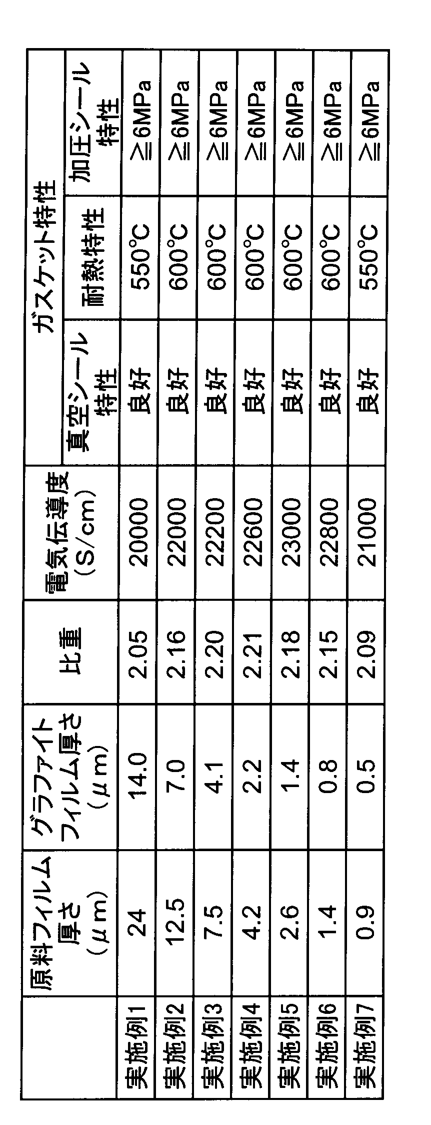
- Each of the graphite films of Examples 1 to 7 produced by such a method is a film having a uniform structure containing almost no air bubbles inside the film, and its specific gravity is 2.05 or more, and the electric power in the film surface direction is The conductivity was 20000 S / cm or more.
- the thickness of a graphite film obtained from a film having a thickness of 12.5 ⁇ m was 7.0 ⁇ m
- the electric conductivity in the plane direction was 2.2 ⁇ 10 4 S / cm
- the specific gravity was 2.16.
- Example 2 the specific gravity
- the purity of each film was almost 100% carbon
- the metal impurities were several ppm or less
- elements such as nitrogen, oxygen, and hydrogen were not detected. That is, it can be seen that a high quality film was obtained by this method.
- This measuring apparatus 10 is configured by a generally bottomed cylindrical stainless steel pressure-resistant chamber 1 having a flange portion 3 and a flat member 6 a that covers the opening of the chamber 1.
- a ring-shaped graphite film 5 can be sandwiched between the flange portions 3, and the inside of the chamber 1 is hermetically sealed by tightening with a plurality of bolt / nut pairs 4 provided along the circumferential direction of the flange portion 3. it can.
- a stainless steel pipe 6b is attached to the center of the flat member 6a.
- the pipe 6b is connected to a compressor (not shown) or a vacuum pump (not shown) via a cock or a valve 8.
- the inside or outside of the chamber can be depressurized (vacuum) or pressurized by opening and closing the cock or valve 8.
- the degree of depressurization and the degree of pressurization are pressure gauges (vacuum) provided by branching from the pipe 6 b. Measurement is possible with a pressure gauge) 7.
- the measuring device 10 is installed in the electric furnace 2 and can be heated together with the measuring device.
- Example 1 and Example 7 shows that the change in the degree of vacuum was less than 1% at 550 ° C., but the change in the degree of vacuum became 1% or more at 600 ° C.
- the description at 600 ° C. in Examples 2 to 6 indicates that the change in the degree of vacuum was less than 1% at 600 ° C., but the change in the degree of vacuum was 1% or more at 650 ° C. From these results, it was concluded that the heat resistance characteristics of the samples of Example 1 and Example 7 were 550 ° C. and that of Examples 2 to 6 was 600 ° C.
- a graphite film (Comparative Example 1) obtained by using a raw material film having a thickness of 50 ⁇ m and treated under normal pressure contains almost no bubbles inside the film, and the appearance is the same as that of the graphite film obtained in Example 1. It was a film.
- the graphite films of Comparative Examples 2 and 3 treated under the pressures of 0.05 MPa and 0.2 MPa were in a uniform foamed state. The foamed film was rolled by passing between two stainless steel rollers.
- the graphite film obtained by using a raw material film having a thickness of 75 ⁇ m and processing under normal pressure is a brittle (battered) film, unlike the graphite film obtained in Example 1, and is electrically conductive in the plane direction. It was also difficult to accurately measure the degree (Comparative Example 4).
- the graphite film treated under the pressures of 0.05 MPa and 0.2 MPa was in a uniform foamed state, and a flexible film was obtained by performing a rolling treatment through two stainless steel rollers ( Comparative examples 5 and 6), respectively.
- the electric conductivity in the plane direction of the graphite film was 14000 S / cm to 14700 S / cm.
- Example 1 the apparatus 10 on which the graphite film was set was placed in an electric furnace at 400 ° C., and the change in the degree of vacuum was examined.
- the change in the degree of vacuum after the lapse of 10 hours was less than 1%, indicating an extremely excellent sealing property.
- the temperature of the electric furnace was increased to 450 ° C.
- the degree of vacuum decreased. From this result, it was found that the heat resistance of the samples of Comparative Examples 2, 3, 5, and 6 was 400 ° C. or higher and lower than 450 ° C.
- the graphite films described in Examples 1 to 7 have high electrical conductivity in the plane direction, which is an index indicating whether or not they are high density and high quality. Since the sealing properties can be exhibited without cracking even under pressure, the gasket properties obtained from such a graphite film are more than 150 ° C. in heat resistance compared to the properties of gasket films produced by foaming (Comparative Examples 2, 3, 5, 6). The pressure resistance exceeded 2 MPa and was found to be extremely excellent gasket characteristics.
- Example 8 and 9 (Comparative Examples 7 to 9)
- a PMDA / ODA type polyimide film (commercially available AH film manufactured by Kaneka Corporation) with a thickness of 12.5 ⁇ m was heated to 1000 ° C. at a rate of 10 ° C./min in nitrogen gas using an electric furnace. Pre-heat treatment was performed for 1 hour. Next, the obtained carbonized film was laminated and set on a graphite plate, and it was set at 2200 ° C. (Comparative Example 7) and 2400 ° C. (Comparative Example 8) respectively at a rate of 20 ° C./min with a graphite tube using a graphitization furnace. ) Heated to 2600 ° C.
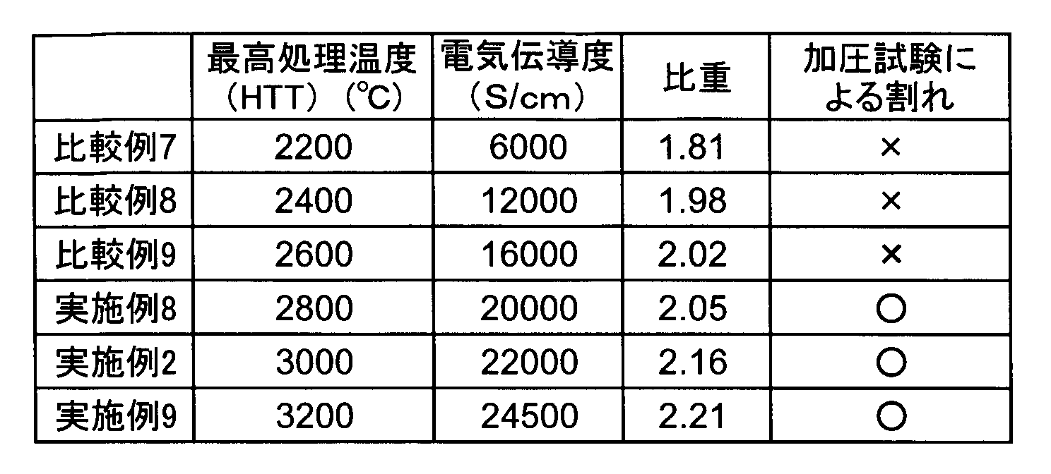
- Each graphite film obtained was measured for electrical conductivity and specific gravity in the plane direction, and this film was sandwiched between mirror-polished stainless steel plates (diameter 5 cm), and a load of 5 kg / cm 2 was applied thereto to cause cracks. Tested whether to do. The results are shown in Table 3.
- the pressure test is performed using 5 films for each sample. If one of them is cracked, it cannot be used (shown as x in Table 3), and it can be used when no crack is generated. (Indicated as a circle in Table 3).
- the maximum processing temperature is 2800 ° C.
- Example 10 Five graphite gaskets (thickness: 4.1 ⁇ m) used in Example 3 were stacked to form a graphite gasket of about 20 ⁇ m.
- the gasket was measured for vacuum seal characteristics, heat resistance, and pressure seal characteristics by the same method as in Example 1. As a result, the vacuum seal characteristics were good, the heat resistance characteristics were 600 ° C., and the pressure seal characteristics were 6 MPa or more. From this experiment, it was found that the graphite gasket of the present invention showed good characteristics even when laminated in multiple layers.
- Example 11 The graphite gasket (thickness 14.0 ⁇ m) and the copper foil (thickness 10 ⁇ m) used in Example 1 were laminated in the order of graphite gasket / copper foil / graphite gasket and pressed at 950 ° C. and a pressure of 100 kg / cm 2. Thus, a gasket having a metal core material was produced. The vacuum seal characteristics were good, the heat resistance was 600 ° C., and the pressure seal characteristics were 6 MPa or more, both of which were good. From this result, it was found that the graphite gasket of the present invention showed good characteristics even as a composite structure with metal.
- the present invention relates to a film-like graphite gasket having both toughness and elasticity and improved vacuum sealability, heat resistance, and pressure seal properties. Therefore, the graphite gasket of the present invention is suitable for maintaining the air tightness and liquid tightness of various devices, and is industrially useful because it can be used in industrial fields such as various plants, building facilities and shipbuilding.
Landscapes
- Chemical & Material Sciences (AREA)
- Engineering & Computer Science (AREA)
- Organic Chemistry (AREA)
- General Engineering & Computer Science (AREA)
- Geology (AREA)
- General Life Sciences & Earth Sciences (AREA)
- Inorganic Chemistry (AREA)
- Life Sciences & Earth Sciences (AREA)
- Mechanical Engineering (AREA)
- Materials Engineering (AREA)
- Gasket Seals (AREA)
- Sealing Material Composition (AREA)
- Carbon And Carbon Compounds (AREA)
Abstract
高分子焼成法によるガスケットを改良することによって、優れた真空シール特性を示すだけでなく、従来のグラファイトガスケットの課題である耐熱性、耐圧性を改善することを目的とする。本発明は、厚さ15μm未満、0.5μm以上であり、面方向の電気伝導度が20000S/cm以上であるグラファイトフィルムからなるガスケットである。前記グラファイトフィルムの比重は2.05以上、2.26未満であることが好ましい。本発明のグラファイトガスケットは、高分子フィルムを加圧下、2800℃以上の温度で熱処理することによって得ることができる。
Description
本発明はグラファイト(黒鉛)からなるガスケットに関する。ガスケットは相対運動しない接触面に挟んで使用する漏れ止め用の固定シールである。最も一般的な方法では、配管の継ぎ手や、圧力容器本体とマンホールの間、又はバルブボンネットとバルブボディの間に設けられたフランジの間へガスケットを挟み込み、フランジを締め付けて気密を得て流体の漏れ又は外部からの異物の進入を防止する。
ガスケットは、耐熱又は耐寒性、耐圧性、耐溶剤性、耐油性、耐薬品性、施工性、加工性、価格などに応じて様々な種類のものが開発されている。ガスケットは各種装置の気密性や液密性を保持するために必要とされるため、石油精製、石油化学、発電所などのプラント、ビル設備、造船等の各種分野で使用される。一般的に内部圧力や温度が低い用途にはゴムや熱可塑性エラストマーなどの軟質ガスケットが用いられ、内部圧力や温度が高い用途ではメタルジャケットガスケットなどのセミメタルガスケットやメタルガスケットが用いられる。
例えば、メタルジャケットガスケットは高温・高耐圧用途のガスケットで、無機質の中芯クッション材を金属薄板で被覆したガスケットであり、被覆金属には銅やステンレスの薄板が用いられる事が多い。汎用グレードでの使用温度範囲は530℃以下、耐圧は6.0MPaである。また、高温グレードの使用温度範囲は1300℃以下、耐圧は6.0MPa、高耐圧グレードの使用温度範囲は600℃以下、耐圧は40MPaである。メタルジャケットガスケットは表面が金属であるため浸透漏れがなく耐熱性が高く、特に被覆金属として銅を用いた物はフランジの接触面との馴染み性が高いと言う特徴がある。そのためディーゼルエンジン、高温配管、反応器、熱交換器などに使用されている。メタルジャケットガスケットはこの様に優れた特性を有するものの、硬いため、高い締付け面圧が必要であるという問題や、恒久的な組み立て用であり、一度使用されると変形しフランジ表面を傷つけるためガスケットもフランジも再使用出来なくなると言う問題がある。
この様なガスケットの一種類として、柔らかい事を特徴とする膨張黒鉛を基材とするフィルム状ガスケットがあり、汎用のガスケットとして広く使用されている(特許文献1~5)。膨張黒鉛は主に天然グラファイトを濃硫酸と濃硝酸の混合液に浸漬し、その後、加熱によりグラファイト層間を広げる事により薄片化して製造される。この様にして製造されたグラファイトは洗浄により酸を取り除いたのち、高圧プレスすることによってフィルム状に加工される。この膨張黒鉛ガスケットは柔らかいと言う特徴があるものの、黒鉛粉末より製造されるためフィルム強度は弱く、また、フィルムを使用する際に製造工程で使用された酸が完全には取り除けないため、その残留酸の浸出によるフランジ金属などの腐食の問題があった。そのため、膨張黒鉛ガスケットは硫黄や酸をきらう高温高圧系や高真空系には使用出来なかった。
この膨張黒鉛を基材とするガスケットには強度を補強するために補強材として中芯にステンレス鋼板を挟んだものと挟まないものがある。ステンレス鋼板を挟まないものの最高使用温度は350℃、挟んだものの最高使用温度は400℃である。また、ステンレス鋼板を挟まないものの耐圧は3MPaまで、ステンレス鋼板を挟んだものの耐圧は5MPaまでと言われている。
この様に膨張黒鉛ガスケットは耐薬品性に優れ、汎用用途として広く使用されるガスケットであるが、その耐圧(シール)特性、耐熱特性は前述のメタルジャケットガスケットに比べて劣っており、より高温度や高耐圧で使用できるガスケットが望まれており、これが第一の課題である。また、第二の課題は前記の残留酸による金属腐食の問題であり、第三の課題は、ステンレス鋼板を挟んだものの場合、表面の膨張黒鉛が軟らかく中芯が硬いことから、加工が難しく傷つき易く慎重に取り扱う必要があると言う点である。
この様な問題を解決するため、特殊な高分子フィルムを熱処理(以下高分子焼成法と記載する)して得られたグラファイトを用いて作製されたガスケットが開発されている(特許文献6)。この方法では原料フィルムの厚さを25μm以上、400μm以下とし、フィルム内部から発生するガスを用いて発泡状態のグラファイトフィルムを作製し、その後これを圧延処理(例えば、ロール掛けなどの方法が用いられる)する事により、ガスケットとして使用可能な柔軟なグラファイトフィルムを作製する。高分子焼成法は膨張黒鉛ガスケットとは異なり、残留酸による金属腐食の問題のない優れた方法であり、前記第二の課題はこの方法で解決され、またフィルムの強度が膨張黒鉛フィルムよりも強いため単独で用いる事が可能で第三の課題も解決された。
しかしながら、特許文献6で示される高分子焼成法で得られたグラファイトガスケットは、後述する実施例で示す通り、その最高使用温度が400℃、耐圧が4MPaであって、耐熱性や耐圧性の点からは膨張黒鉛ガスケットと比較して大きな特性改良が成されたものではなかった。
本発明は、高分子焼成法によるガスケットを改良する事によって、優れた真空シール特性を示すだけでなく、従来のグラファイトガスケットの課題である耐熱性、耐圧性(後述する加圧シール特性)をも大幅に改良することを目的とする。
上記課題を達成した本発明は、厚さ15μm未満、0.5μm以上であり、面方向の電気伝導度が20000S/cm以上であるグラファイトフィルムからなるガスケットである。前記グラファイトフィルムの比重は、2.05以上、2.26未満であることが好ましい。また前記グラファイトフィルムは、高分子フィルムを加圧下、2800℃以上の温度で熱処理して得られることが好ましく、特に該高分子フィルムが厚さ25μm未満、0.9μm以上の芳香族ポリイミドであることが好ましい。
本発明は、上記したいずれかのグラファイトフィルムが複数枚積層された積層ガスケットを包含する。また本発明は、金属フィルムからなる芯材の両面に、上記したいずれかのグラファイトフィルムが単層で、又は積層して配設されている金属芯付きガスケットも包含する。
本発明のガスケットに用いられるグラファイトフィルムは、厚さが15μm未満と薄く、面方向の電気伝導度が20000S/cm以上と高い。こうしたグラファイトフィルムは、優れた層構造を有しており、耐熱性に優れており、しかも強靭で加圧しても割れが発生せず、加圧シール特性も大幅に改良できる。グラファイト粉末から膨張黒鉛法で得られるグラファイトガスケットや、高分子焼成グラファイトの発泡・圧延処理によって得られるグラファイトガスケットでは、高い電気伝導度(優れた層構造)を示さず、優れたシール特性(特に、加圧シール特性)、耐熱性などを示さない。
また、本発明のグラファイトフィルムからなるガスケットは、メタルジャケットガスケットに匹敵するシール特性(真空シール性及び加圧シール特性)及び耐熱性を有し、しかもメタルジャケットガスケットとは異なり、簡易に再組み立てが可能である。
また、本発明のグラファイトフィルムからなるガスケットは、メタルジャケットガスケットに匹敵するシール特性(真空シール性及び加圧シール特性)及び耐熱性を有し、しかもメタルジャケットガスケットとは異なり、簡易に再組み立てが可能である。
上記特許文献6に示される従来の高分子焼成法によるガスケット作製法では、原料フィルムの厚さを25μm以上、400μm以下とし、フィルム内部から発生するガスを用いて発泡状態のグラファイトフィルムを作製し、その後これを圧延処理する事により、ガスケットとして使用可能な柔軟なグラファイトフィルムを作製する。この様な煩雑な処理プロセスが必要である理由は、厚さ25μm程度以上の原料フィルムを用い、発泡させずに作製したグラファイトフィルムは硬く、例えば、これをガスケットとしてフランジの間に挟み、締め付けを行なうと、フィルムが割れてしまい、ガスケットとしての役割を果たさないためである。
本発明者らはこの点に注目し解決すべく検討を行った。その結果、以下の知見を得る事が出来た。
(1)25μm以上の厚さの原料フィルムを用い、これを発泡しない様にグラファイト化すると、厚さ15~17μm程度のグラファイトフィルムが得られる。
(2)このフィルムは、例えばフランジによる締め付けにより、割れる場合と割れない場合があり、無論、割れる場合にはガスケットとして使用する事は出来ない。
(3)一方、割れない様に締め付けが出来た場合にはガスケットとして非常に優れたシール特性や耐熱特性を発現する。
(4)しかしながら、例えば50μmの厚さの原料フィルムを用いて、発泡しない様に作製した厚さ25~27μmのグラファイトフィルムはどの様にしてもフランジ間に挟む事で割れてしまう。
(5)即ち、発泡していないグラファイトフィルムが加圧によって割れるかどうかは、その厚さによって決まると推測され、その境界は15μm程度の厚さである。
(1)25μm以上の厚さの原料フィルムを用い、これを発泡しない様にグラファイト化すると、厚さ15~17μm程度のグラファイトフィルムが得られる。
(2)このフィルムは、例えばフランジによる締め付けにより、割れる場合と割れない場合があり、無論、割れる場合にはガスケットとして使用する事は出来ない。
(3)一方、割れない様に締め付けが出来た場合にはガスケットとして非常に優れたシール特性や耐熱特性を発現する。
(4)しかしながら、例えば50μmの厚さの原料フィルムを用いて、発泡しない様に作製した厚さ25~27μmのグラファイトフィルムはどの様にしてもフランジ間に挟む事で割れてしまう。
(5)即ち、発泡していないグラファイトフィルムが加圧によって割れるかどうかは、その厚さによって決まると推測され、その境界は15μm程度の厚さである。
本発明者らはこの様な知見に基づきさらに検討を行った。その結果、グラファイトフィルムが薄くなるほど、グラファイトの層構造がさらに改善されやすくなること、そして電気伝導度が20000S/cm以上となる程度まで層構造を改善すると強靭なフィルムとなり、加圧やフランジへの挟み込みによって割れず、さらにはグラファイトフィルムの真空シール特性、耐熱特性(真空時耐熱特性)、加圧シール特性なども著しく改善される事を発見した。なお特許文献6は、グラファイトフィルムの強靭性に着目しているために、原料フィルムの厚みが25μm程度である場合には圧力下での熱処理は必要ないと開示しているが、こうした特許文献6が否定し、かつ具体的に実施していない条件が、実は前記電気伝導度の向上(グラファイト層構造の改善)に有効に作用し、耐熱特性、加圧シール特性を向上するのに有効であった。こうした薄くて電気伝導度の高いグラファイトフィルムがガスケットとして極めてすぐれた特性を発揮できることを見出し、本発明を成すに至った。
本発明のガスケットに用いるグラファイトフィルムの厚さは15μm未満であり、12μm以下が好ましく、最も好ましい厚さは10μm以下である。これら薄いグラファイトフィルムは、その層構造(電気伝導度)がさらに改善されており、10μm以下の厚さの場合加圧によって割れる事はほとんど無くなる。一方、本発明のグラファイトフィルムの厚さの下限は、0.5μm以上であり、0.7μm以上がより好ましく、1μm以上である事は更に好ましく、2μm以上である事は最も好ましい。0.5μm未満の厚さでは、グラファイトフィルムを自立膜として取り扱う事が極めて困難となり、真空シール性や加圧シール性も低下する傾向にあり、本発明のガスケット用途として好ましくない。本発明のグラファイトフィルムは、好ましくは15μm未満、0.7μm以上であり、より好ましくは12μm以下、1μm以上であり、更に好ましくは10μm以下、2μm以上である。
また、本発明のグラファイトフィルムは、高い電気伝導度を示す。電気伝導度は、グラファイトフィルムの層構造の緻密さ乃至整合性を反映したものであり、該グラファイトフィルムが高密度・高品質グラファイトであるか、また強靭で加圧によっても割れないかどうかの指標として有効である。この電気伝導度が小さいと(特に16000S/cm以下である場合)、グラファイト化が十分に進行しておらず、ガラス状炭素と呼ばれる状態である事もあり、極めて硬いため、例えグラファイトフィルムの厚さが15μm未満であったとしても、加圧や挟み込みによってガスケットは割れてしまう。本発明のグラファイトフィルムでは、a-b面方向の電気伝導度を20000S/cm以上としており、このようにすることで優れたガスケット性能が実現できる。面方向の電気伝導度は20000S/cm超が好ましく、21000S/cm以上であることがより好ましく、21500S/cm以上であることがさらに好ましく、22000S/cm以上であることが特に好ましい。フィルム面方向の電気伝導度の上限には制限はないが、過去に報告された最高値である25000S/cmの値が一つの目安になる。
前記本発明のグラファイトフィルムの比重(密度)は、例えば、2.05(g/cm3)以上、2.26(g/cm3)未満であることが好ましい。比重(密度)2.26(g/cm3)の値はグラファイト単結晶の値であってグラファイトの最大比重に相当する。この様に比重を高くすることで、真空シール性や加圧シール性をさらに高めることができる。本発明のグラファイトフィルムの比重(密度)は、2.10(g/cm3)以上がより好ましく、更に好ましくは2.15(g/cm3)以上である。従来の膨張黒鉛や従来の高分子焼成法グラファイトからなるガスケットは、柔軟性を付与するために膨張や発泡という手法を用いるために、グラファイトの比重(密度)は低く、真空シール性や加圧シール性は低い。
なお好ましい態様を含めた本発明のグラファイトガスケットは、以上の通り、薄く、高電気伝導度で、かつ高比重という特徴を有しており、これらは高密度、高熱伝導率、強靭性という特性に換言する事も可能である。すなわち好ましい態様を含めた本発明のガスケットは、(1)高密度で強靭であるために締め付けによっても割れる事がないと言う特徴を持っており、さらに(2)膜厚が薄くて空気や輸送流体と接触する断面積が小さく、(3)高い熱伝導率を有し、熱がガスケット部分に溜まらないという特徴を有しているとも言える。本発明のグラファイトフィルムのa-b面方向の熱伝導率は、例えば1800W/mK以上であり、好ましくは1900W/mK以上、より好ましくは1950W/mK以上、最も好ましくは2000W/mK以上である。熱伝導率は、例えば2400W/mK以下であっても良く、2300W/mK以下であっても良い。
上記の様な特性を有する本発明のグラファイトフィルムからなるガスケット(以下、グラファイトガスケットと呼ぶ)は極めてすぐれた耐熱性及びシール特性を有し、その耐熱性は550℃以上(好ましくは600℃以上)、耐圧性は6MPa以上である。つまり、本発明のグラファイトガスケットは、従来の膨張黒鉛ガスケットや高分子焼成法による発泡グラファイトガスケットと比較して耐熱性では150℃以上、耐圧性でも2MPa以上すぐれている事が分かった。驚くべき事に、その特性は汎用グレードのメタルジャケットガスケットの特性に匹敵するものである。
前記本発明のガスケットに用いるグラファイトフィルムは、高分子焼成法により製造される。このグラファイトフィルムの製造方法の要点は、(1)原料フィルムとして特定の分子構造を有する高分子を用いる事、(2)特定の範囲の厚みを有する原料フィルムを用いる事、(3)特定以上の温度で加圧下で原料フィルムを熱処理する事、に要約する事が出来る。厚さを薄くして、高温で加圧下で熱処理することは、グラファイト化時に形成される層を高度に均質化するのに有効であり、こうした製法によることで、面方向の電気伝導度の高いグラファイトフィルムを得ることができる。
以下、本発明のグラファイトガスケットの製造方法を、用いる高分子原料、該高分子原料の製造方法、高分子原料の炭素化・グラファイト化、ガスケット加工の順に説明する。
<高分子原料>
原料となる高分子フィルムとしては、芳香族高分子が挙げられ、具体的には各種ポリフェニレンオキサジアゾール(POD)、ポリベンゾチアゾール(PBT)、ポリベンゾビスチアゾール(PBBT)、ポリベンゾオキサゾール(PBO)、ポリベンゾビスオキサゾール(PBBO)、各種芳香族ポリイミド(PI)、ポリ(フェニレンイソフタルアミド)(PPA)、ポリ(フェニレンベンゾイミタゾール)(PBI)、ポリ(フェニレンベンゾビスイミダゾール)(PPBI)、ポリチアゾール(PT)、ポリ(パラフェニレンビニレン)(PPV)のうちから選ばれた少なくとも一種類を用いることができる。芳香族ポリイミドは本発明のガスケットを作製する原料高分子として好ましく、中でも以下に記載する酸二無水物(特に芳香族酸二無水物)とジアミン(特に芳香族ジアミン)からポリアミド酸を経て作製される芳香族ポリイミドが特に好ましい。
原料となる高分子フィルムとしては、芳香族高分子が挙げられ、具体的には各種ポリフェニレンオキサジアゾール(POD)、ポリベンゾチアゾール(PBT)、ポリベンゾビスチアゾール(PBBT)、ポリベンゾオキサゾール(PBO)、ポリベンゾビスオキサゾール(PBBO)、各種芳香族ポリイミド(PI)、ポリ(フェニレンイソフタルアミド)(PPA)、ポリ(フェニレンベンゾイミタゾール)(PBI)、ポリ(フェニレンベンゾビスイミダゾール)(PPBI)、ポリチアゾール(PT)、ポリ(パラフェニレンビニレン)(PPV)のうちから選ばれた少なくとも一種類を用いることができる。芳香族ポリイミドは本発明のガスケットを作製する原料高分子として好ましく、中でも以下に記載する酸二無水物(特に芳香族酸二無水物)とジアミン(特に芳香族ジアミン)からポリアミド酸を経て作製される芳香族ポリイミドが特に好ましい。
前記芳香族ポリイミドの合成に用いられ得る酸二無水物としては、ピロメリット酸無水物、2,3,6,7-ナフタレンテトラカルボン酸二無水物、3,3’,4,4’-ビフェニルテトラカルボン酸二無水物、1,2,5,6-ナフタレンテトラカルボン酸二無水物、2,2’,3,3’-ビフェニルテトラカルボン酸二無水物、3,3’,4,4’-ベンゾフェノンテトラカルボン酸二無水物、2,2-ビス(3,4-ジカルボキシフェニル)プロパン二無水物、3,4,9,10-ペリレンテトラカルボン酸二無水物、ビス(3,4-ジカルボキシフェニル)プロパン二無水物、1,1-ビス(2,3-ジカルボキシフェニル)エタン二無水物、1,1-ビス(3,4-ジカルボキシフェニル)エタン二無水物、ビス(2,3-ジカルボキシフェニル)メタン二無水物、ビス(3,4-ジカルボキシフェニル)エタン二無水物、オキシジフタル酸二無水物、ビス(3,4-ジカルボキシフェニル)スルホン二無水物、p-フェニレンビス(トリメリット酸モノエステル酸無水物)、エチレンビス(トリメリット酸モノエステル酸無水物)、ビスフェノールAビス(トリメリット酸モノエステル酸無水物)、およびそれらの類似物を含み、それらを単独または任意の割合の混合物で用いることができる。特に非常に剛直な構造を有した高分子構造を持つほどポリイミドフィルムの配向性が高くなること、さらには入手性の観点から、ピロメリット酸無水物、3,3’,4,4’-ビフェニルテトラカルボン酸二無水物が特に好ましい。
前記芳香族ポリイミドの合成に用いられ得るジアミンとしては、4,4’-ジアミノジフェニルエーテル、p-フェニレンジアミン、4,4’-ジアミノジフェニルプロパン、4,4’-ジアミノジフェニルメタン、ベンジジン、3,3’-ジクロロベンジジン、4,4’-ジアミノジフェニルスルフィド、3,3’-ジアミノジフェニルスルホン、4,4’-ジアミノジフェニルスルホン、4,4’-ジアミノジフェニルエーテル、3,3’-ジアミノジフェニルエーテル、3,4’-ジアミノジフェニルエーテル、1,5-ジアミノナフタレン、4,4’-ジアミノジフェニルジエチルシラン、4,4’-ジアミノジフェニルシラン、4,4’-ジアミノジフェニルエチルホスフィンオキシド、4,4’-ジアミノジフェニルN-メチルアミン、4,4’-ジアミノジフェニルN-フェニルアミン、1,4-ジアミノベンゼン(p-フェニレンジアミン)、1,3-ジアミノベンゼン、1,2-ジアミノベンゼンおよびそれらの類似物を含み、それらを単独でまたは任意の割合の混合物で用いることができる。さらにポリイミドフィルムの配向性を高くすること、入手性の観点から、4,4’-ジアミノジフェニルエーテル、p-フェニレンジアミンを原料に用いて合成されることが特に好ましい。
特定の厚みを有する高分子フィルムとは、グラファイト化によって結果的に15μm未満、0.5μm以上のグラファイトフィルムが得られる厚みの事を意味する。グラファイト化時のフィルム厚みの変化は、原料高分子の分子構造によって異なる事になる。例えば、最も好ましい高分子であるピロメリット酸無水物(PMDA)/4,4’-ジアミノジフェニルエーテル(ODA)型芳香族ポリイミドの場合、熱分解によって高分子中の窒素、酸素、水素などの元素が取り除かれ炭素化が進行し、得られた炭素化フィルムは更なる高温での処理によりグラファイト化が進行し、得られるグラファイトフィルムの厚さ方向は原料フィルムのおよそ60%~50%程度になる。そのためにPMDA/ODA型ポリイミドの場合、その好ましい厚さは25μm未満、0.9μm以上となる。また原料高分子フィルムの厚みが薄いほど、グラファイトの層構造が適切になって、電気伝導度が高くなりやすい。原料高分子フィルムの好ましい厚さは、25μm未満、好ましくは22μm以下であり、より好ましくは18μm以下である。
<高分子原料の合成、成膜>
高分子原料としてのポリイミドの製造方法について以下に説明する。ポリイミドの製造方法には、前駆体であるポリアミド酸を加熱でイミド転化する熱キュア法、ポリアミド酸に無水酢酸等の酸無水物に代表される脱水剤や、ピコリン、キノリン、イソキノリン、ピリジン等の第3級アミン類をイミド化促進剤として用い、イミド転化するケミカルキュア法があるが、そのいずれを用いても良い。得られるフィルムの線膨張係数が小さく、弾性率が高く、複屈折率が大きくなりやすく、フィルムの焼成中に張力をかけたとしても破損することなく、また、品質の良いグラファイトを得ることができるという点からケミカルキュア法が好ましい。またケミカルキュア法は、グラファイトフィルムの熱伝導率の向上の面でも優れている。
前記酸二無水物とジアミンからのポリアミド酸の調製には公知の方法を用いることができ、通常、芳香族酸二無水物の少なくとも1種とジアミンの少なくとも1種を有機溶媒中に溶解させ、得られたポリアミド酸有機溶媒溶液を、制御された温度条件下で、上記酸二無水物とジアミンの重合が完了するまで攪拌することによって製造される。これらのポリアミド酸溶液は通常5~35wt%、好ましくは10~30wt%の濃度で得られる。この範囲の濃度である場合に適当な分子量と溶液粘度を得る事が出来る。
前記原料溶液中の酸二無水物とは実質的に等モル量にすることが好ましく、モル比は、例えば、1.5:1~1:1.5、好ましくは1.2:1~1:1.2、より好ましくは1.1:1~1:1.1である。
高分子原料としてのポリイミドの製造方法について以下に説明する。ポリイミドの製造方法には、前駆体であるポリアミド酸を加熱でイミド転化する熱キュア法、ポリアミド酸に無水酢酸等の酸無水物に代表される脱水剤や、ピコリン、キノリン、イソキノリン、ピリジン等の第3級アミン類をイミド化促進剤として用い、イミド転化するケミカルキュア法があるが、そのいずれを用いても良い。得られるフィルムの線膨張係数が小さく、弾性率が高く、複屈折率が大きくなりやすく、フィルムの焼成中に張力をかけたとしても破損することなく、また、品質の良いグラファイトを得ることができるという点からケミカルキュア法が好ましい。またケミカルキュア法は、グラファイトフィルムの熱伝導率の向上の面でも優れている。
前記酸二無水物とジアミンからのポリアミド酸の調製には公知の方法を用いることができ、通常、芳香族酸二無水物の少なくとも1種とジアミンの少なくとも1種を有機溶媒中に溶解させ、得られたポリアミド酸有機溶媒溶液を、制御された温度条件下で、上記酸二無水物とジアミンの重合が完了するまで攪拌することによって製造される。これらのポリアミド酸溶液は通常5~35wt%、好ましくは10~30wt%の濃度で得られる。この範囲の濃度である場合に適当な分子量と溶液粘度を得る事が出来る。
前記原料溶液中の酸二無水物とは実質的に等モル量にすることが好ましく、モル比は、例えば、1.5:1~1:1.5、好ましくは1.2:1~1:1.2、より好ましくは1.1:1~1:1.1である。
ポリイミドフィルムは、例えば、上記ポリイミド前駆体であるポリアミド酸の有機溶剤溶液をエンドレスベルト、ステンレスドラムなどの支持体上に流延し、乾燥・イミド化させることにより製造される。具体的にケミカルキュアによるフィルムの製造法は以下のようになる。まず上記ポリアミド酸溶液に化学量論以上の脱水剤と触媒量のイミド化促進剤を加え支持板やPET等の有機フィルム、ドラム又はエンドレスベルト等の支持体上に流延又は塗布して膜状とし、有機溶媒を蒸発させることにより自己支持性を有する膜を得る。次いで、これを更に加熱して乾燥させつつイミド化させポリイミドフィルムを得る。加熱の際の温度は、150℃から550℃の範囲の温度が好ましい。さらに、ポリイミドの製造工程中に、収縮を防止するためにフィルムを固定したり、延伸したりする工程を含む事が好ましい。これは、分子構造およびその高次構造が制御されたフィルムを用いる事でグラファイトへの転化がより容易に進行する、と言う事によっている。すなわち、グラファイト化反応をスムーズに進行させるためには炭素前駆体中の炭素分子が再配列する必要があるが、配向性にすぐれたポリイミドではその再配列が最小で済むために、低温でもグラファイトへの転化が進み易いと推測される。
<炭素化・グラファイト化>
次に、ポリイミドに代表される高分子フィルムの炭素化・グラファイト化の手法について述べる。本発明では出発物質である高分子フィルムを不活性ガス中で予備加熱し、炭素化を行う。不活性ガスは、窒素、アルゴンあるいはアルゴンと窒素の混合ガスが好ましく用いられる。予備加熱は通常1000℃程度で行う。予備加熱温度までの昇温速度は特に限定されないが、例えば5~15℃/分である。予備処理の段階では出発高分子フィルムの配向性が失われない様に、フィルムの破壊が起きない程度の面方向の圧力を加える事が有効である。
次に、ポリイミドに代表される高分子フィルムの炭素化・グラファイト化の手法について述べる。本発明では出発物質である高分子フィルムを不活性ガス中で予備加熱し、炭素化を行う。不活性ガスは、窒素、アルゴンあるいはアルゴンと窒素の混合ガスが好ましく用いられる。予備加熱は通常1000℃程度で行う。予備加熱温度までの昇温速度は特に限定されないが、例えば5~15℃/分である。予備処理の段階では出発高分子フィルムの配向性が失われない様に、フィルムの破壊が起きない程度の面方向の圧力を加える事が有効である。
上記の方法で炭素化されたフィルムを高温炉内にセットし、グラファイト化を行なう。炭素化フィルムのセットはグラファイト板(例えばCIP材)やグラッシーカーボン基板に挟んで行う事が好ましい。本発明で、グラファイトフィルムの面方向の電気伝導度を20000S/cm以上とするためには、特定以上の温度と圧力で熱処理することが重要である。
熱処理温度を2600℃超とすることで、得られるグラファイトフィルムが強靭で加圧によっても割れないフィルムとなる。2600℃以下の温度での熱処理の場合には、上記した高分子原料を用い、さらに本発明の範囲の厚さのグラファイトであっても、得られるフィルムは硬く、挟む事により割れが生じてガスケットとして用いる事が出来ない。本発明のグラファイトフィルムは、前記高分子フィルムを不活性ガス中2800℃以上(特に2800℃超)の温度で熱処理する事によって得られる。このようにすることで、グラファイトフィルムの面方向の電気伝導度を20000S/cm以上(特に20000S/cm超)にでき、グラファイトフィルムはガスケットとして使用可能な強靭性と柔軟性を具備する様になり、加圧によって割れなくなると共に、優れたガスケット性能を実現できる。上記の高分子原料を用いて2800℃以上で処理しても、グラファイトフィルムの厚さが15μm以上である場合には、加圧により割れが生じてガスケットとして使用する事が困難となる事はすでに記載した通りである。熱処理温度は2900℃以上である事がより好ましく、3000℃以上である事は最も好ましい。この様な高温を作り出すには、通常グラファイトヒーターに直接電流を流し、そのジュ-ル熱を利用して加熱を行なう。
グラファイト化は不活性ガス中で行なう。不活性ガスとしてはアルゴンが最も適当であり、アルゴンに少量のヘリウムを加えても良い。処理温度は高ければ高いほど良質のグラファイトに転化出来る。熱分解と炭素化によりその面積は元のポリイミドフィルムより約10~40%程度収縮し、グラファイト化の過程では逆に約10%程度拡大する事が多い。このような収縮、拡大によってグラファイトシート内には内部応力が発生しグラファイトシート内部にひずみが発生する。この様なひずみや内部応力は2800℃以上で処理することにより緩和されてグラファイトの層が規則正しく配列し、電気伝導率が高くなる。この処理温度はグラファイト化過程における最高処理温度としても良く、得られたグラファイトシートをアニーリングの形で再熱処理しても良い。なお処理温度は、例えば、3700℃以下(特に3600℃以下、或いは3500℃以下)であっても、優れたグラファイトフィルムが得られる。前記予備加熱温度から当該最高処理温度までの昇温速度は、例えば15~25℃/分である。
無論、20000S/cm以上のフィルム面方向の電気伝導度を実現するためには、最高処理温度での保持時間や出発原料の厚さなども影響を与えるが、その影響は最高処理温度ほどには大きくない。一般に、保持時間は10分以上である事が好ましく、30分以上である事はより好ましく、1時間以上である事は最も好ましい。保持時間の上限は特に限定されないが、通常、5時間以下、特に3時間以下程度としてもよい。また、20000S/cm以上のフィルム面方向の電気伝導度の達成には出発高分子原料の厚さが薄い程、保持時間は短時間でよい。
無論、20000S/cm以上のフィルム面方向の電気伝導度を実現するためには、最高処理温度での保持時間や出発原料の厚さなども影響を与えるが、その影響は最高処理温度ほどには大きくない。一般に、保持時間は10分以上である事が好ましく、30分以上である事はより好ましく、1時間以上である事は最も好ましい。保持時間の上限は特に限定されないが、通常、5時間以下、特に3時間以下程度としてもよい。また、20000S/cm以上のフィルム面方向の電気伝導度の達成には出発高分子原料の厚さが薄い程、保持時間は短時間でよい。
更に、高温炉内の雰囲気は前記不活性ガスによって加圧されていることが重要である。これによって表面のグラファイト層の乱れを低減でき、グラファイトの層構造を適切なものとすることができる。加圧しないで熱処理すると、フィルム表面に凹凸ができ、ガスケットとして好ましくない。不活性ガスによる高温炉の雰囲気圧力(ゲージ圧)は、例えば、0.02MPa以上、好ましくは0.05MPa以上、さらに好ましくは0.1MPa以上である。この雰囲気圧力の上限は特に限定されないが、例えば、5MPa以下、特に4MPa以下程度であってもよい。熱処理後は、例えば30~50℃/分の速度で降温すれば良い。
上述の通り、本発明は上記の条件を満たすグラファイトフィルムが、強靭で柔軟性に富み、例えばフランジに強く挟持しても割れる事がなく、更にガスケットとして非常にすぐれた真空シール特性、耐熱特性、加圧シール特性、耐薬品特性を有する事を発見して成されたものである。本発明のグラファイトフィルムはその優れた物理的な性質により単独で用いても、優れたシール性、耐熱性、耐圧性、耐薬品性を示すため、本発明のグラファイトフィルムをガスケット形状(リング形状など)に加工し、単層でガスケットとして用いても良い。
また、複数枚のグラファイトフィルムを重ねて使用しても同様な優れた性質を示す。すなわち、本発明のグラファイトフィルムからなるガスケットを複数枚積層して積層ガスケットとして用いても良い。積層ガスケットの厚みは、例えば5~100μm(好ましくは10~60μm)とすれば良く、積層枚数は例えば2~10枚である。
更に、この発明により得られたグラファイトフィルムは、いろいろな金属フィルムを芯材として、該金属フィルムとの複合体として使用することも出来る。用いられる金属としては、銅、鉄、クロム、ニッケル、等の金属元素以外にステンレス鋼などの合金等が広く用いられ、グラファイトフィルムとの積層構造を形成して使用される。具体的には、金属フィルムからなる芯材の両面に、本発明のグラファイトフィルムを単層で配設するか、又は積層して配設し、金属芯付きガスケットとして用いても良い。金属芯付きガスケットの厚みは、例えば5~100μm(好ましくは10~60μm)とすれば良く、グラファイトフィルムの積層枚数は、例えば片面で1~10枚である。
更に、この発明により得られたグラファイトフィルムは、いろいろな金属フィルムを芯材として、該金属フィルムとの複合体として使用することも出来る。用いられる金属としては、銅、鉄、クロム、ニッケル、等の金属元素以外にステンレス鋼などの合金等が広く用いられ、グラファイトフィルムとの積層構造を形成して使用される。具体的には、金属フィルムからなる芯材の両面に、本発明のグラファイトフィルムを単層で配設するか、又は積層して配設し、金属芯付きガスケットとして用いても良い。金属芯付きガスケットの厚みは、例えば5~100μm(好ましくは10~60μm)とすれば良く、グラファイトフィルムの積層枚数は、例えば片面で1~10枚である。
上記した積層ガスケット及び金属芯付きガスケットのいずれにおいても、各フィルムは積層前又は積層後にガスケット形状(リング形状など)に加工するのが好ましく、積層後に各層間の接合性を高めるため、積層体の一部を重なりあったまま折り曲げてもよい。この折り曲げ加工は、積層体の一部に概略U字形状の切り込みを入れ、このU字部を折り返すことで行ってもよい。
本願は、2015年1月9日に出願された日本国特許出願第2015-003515号に基づく優先権の利益を主張するものである。2015年1月9日に出願された日本国特許出願第2015-003515号の明細書の全内容が、本願に参考のため援用される。
以下、実施例により本発明をより具体的に説明する。下記実施例では、芳香族ポリイミドの代表であるPMDA/ODA型芳香族ポリイミドを用いた例を記載するが、上記の高分子や他の芳香族ポリイミドであっても本発明の物性を満たすグラファイトフィルムである限りにおいて優れたガスケットとなる事は明らかである。従って、本発明は高分子の種類を限定するものではなく、その他の細部についても様々な態様が可能である。
物性評価方法は以下の通りである。
(1)膜厚
原料フィルム及びグラファイトフィルムの厚さは、プラス、マイナス5~10%程度の誤差がある。そのため、フィルムの10点平均の厚さを本発明における試料の厚さとした。
(2)比重
ヘリウムガス置換式密度計[Accupyc II 1340 島津製作所(株)]によりグラファイトシートの体積を測定し、質量を別途測定し、質量(g)を体積(cm3)で除すことにより、密度(g/cm3)を算出し、その値をグラファイトシートの比重とした。
(3)電気伝導度
グラファイトシートの電気伝導度は、ファン・デル・ポー法によって測定した。この方法は薄膜状の試料の電気伝導度を測定するのに最も適した方法である。この測定法の詳細は(第四版)実験化学講座9 電気・磁気(社団法人日本化学会編、丸善株式会社、平成3年6月5日発行)のp.170に記載されている。この手法の特徴は、任意の形状の薄膜試料端部の任意の4点に電極をとり測定を行うことが出来、試料の厚さが均一であれば正確な測定が行える点である。本発明においては正方形に切断した試料を用い、それぞれ四つの角(稜)に銀ペースト電極を取り付けて行った。測定は(株)東洋テクニカ製、比抵抗/DC&ACホール測定システム、ResiTest 8300を用いて行った。
(1)膜厚
原料フィルム及びグラファイトフィルムの厚さは、プラス、マイナス5~10%程度の誤差がある。そのため、フィルムの10点平均の厚さを本発明における試料の厚さとした。
(2)比重
ヘリウムガス置換式密度計[Accupyc II 1340 島津製作所(株)]によりグラファイトシートの体積を測定し、質量を別途測定し、質量(g)を体積(cm3)で除すことにより、密度(g/cm3)を算出し、その値をグラファイトシートの比重とした。
(3)電気伝導度
グラファイトシートの電気伝導度は、ファン・デル・ポー法によって測定した。この方法は薄膜状の試料の電気伝導度を測定するのに最も適した方法である。この測定法の詳細は(第四版)実験化学講座9 電気・磁気(社団法人日本化学会編、丸善株式会社、平成3年6月5日発行)のp.170に記載されている。この手法の特徴は、任意の形状の薄膜試料端部の任意の4点に電極をとり測定を行うことが出来、試料の厚さが均一であれば正確な測定が行える点である。本発明においては正方形に切断した試料を用い、それぞれ四つの角(稜)に銀ペースト電極を取り付けて行った。測定は(株)東洋テクニカ製、比抵抗/DC&ACホール測定システム、ResiTest 8300を用いて行った。
(実施例1~7)
原料フィルムとして、厚さ24μm、12.5μm、7.5μm、4.2μm、2.6μm、1.4μm、及び0.9μmのPMDA/ODA型ポリイミドフィルム(7種類)を準備した。
厚さ24μm、12.5μm、7.5μmのポリイミドフィルムは(株)カネカ製の市販AHフィルムである。
厚さ4.2μm、2.6μm、1.4μm、及び0.9μmのPMDA/ODA型ポリイミドフィルムは下記の要領で作製した。すなわち、ピロメリット酸無水物と4,4’-ジアミノジフェニルエーテルをモル比で1/1の割合で合成したポリアミド酸の18wt%のDMF溶液100gに無水酢酸20gとイソキノリン10gからなる硬化剤を混合、攪拌し、遠心分離による脱泡の後、アルミ箔上に流延塗布した。攪拌から脱泡までは0℃に冷却しながら行った。このアルミ箔とポリアミド酸溶液の積層体を120℃で150秒間、300℃、400℃、500℃で各30秒間加熱した後、アルミ箔を除去し、4.2μm、2.6μm、1.4μm、又は0.9μmの厚みのポリイミドフィルムを作製した。
原料フィルムとして、厚さ24μm、12.5μm、7.5μm、4.2μm、2.6μm、1.4μm、及び0.9μmのPMDA/ODA型ポリイミドフィルム(7種類)を準備した。
厚さ24μm、12.5μm、7.5μmのポリイミドフィルムは(株)カネカ製の市販AHフィルムである。
厚さ4.2μm、2.6μm、1.4μm、及び0.9μmのPMDA/ODA型ポリイミドフィルムは下記の要領で作製した。すなわち、ピロメリット酸無水物と4,4’-ジアミノジフェニルエーテルをモル比で1/1の割合で合成したポリアミド酸の18wt%のDMF溶液100gに無水酢酸20gとイソキノリン10gからなる硬化剤を混合、攪拌し、遠心分離による脱泡の後、アルミ箔上に流延塗布した。攪拌から脱泡までは0℃に冷却しながら行った。このアルミ箔とポリアミド酸溶液の積層体を120℃で150秒間、300℃、400℃、500℃で各30秒間加熱した後、アルミ箔を除去し、4.2μm、2.6μm、1.4μm、又は0.9μmの厚みのポリイミドフィルムを作製した。
これらのポリイミドフィルムを、それぞれ電気炉を用いて窒素ガス中10℃/minの速度で1000℃まで昇温し、1000℃で1時間保ち予備熱処理をした。次に得られた炭素化フィルムをグラファイト板に積層してセットし、黒鉛化炉を用いてグラファイト板と共にアルゴン雰囲気中20℃/minの速度で3000℃まで加熱した。3000℃での保持時間は30分間である。加熱は0.15MPa(ゲージ圧)の加圧下で行った。
この様な方法で作製された実施例1~7のグラファイトフィルムはいずれもフィルム内部に気泡をほとんど含まない均一な構造のフィルムであって、その比重は2.05以上であり膜面方向の電気伝導度は20000S/cm以上であった。例えば、厚さ12.5μmのフィルムから得られたグラファイトフィルムの厚さは7.0μmであり、面方向の電気伝導度は2.2×104S/cm、比重は2.16であった(実施例2)。また、元素分析による測定では、いずれのフィルムも純度は、ほぼ100%炭素であり、金属不純物は数ppm以下、窒素、酸素、水素などの元素は検出されなかった。即ち、この手法により高品質なフィルムが得られた事が分かる。これらの結果を表1にまとめて示す。
1.シール特性
次に、得られたグラファイトフィルムの真空シール特性及び加圧シール特性を図1に示す測定装置10を用いて調べた。この測定装置10は、フランジ部3を備えた概略有底筒型のステンレス鋼製耐圧チャンバー1と、このチャンバー1の開口を蓋する平坦部材6aとで構成されている。このフランジ部3には、リング形状に加工したグラファイトフィルム5を挟み込み可能であり、フランジ部3の周方向に沿って設けられた複数のボルト・ナット対4で締め付けることによって、チャンバー1内を密閉できる。そして前記平坦部材6aの中央にはステンレス鋼製パイプ6bが取り付けられており、このパイプ6bは、コック又はバルブ8を介してコンプレッサー(図示せず)又は真空ポンプ(図示せず)に接続しており、このコック又はバルブ8を開閉することでチャンバー内を減圧(真空)又は加圧することが可能であり、減圧度及び加圧度は、前記パイプ6bから分岐して設けられた圧力ゲージ(真空・加圧ゲージ)7によって計測可能である。なお、この測定装置10は、電気炉2内に設置されており、測定装置ごと加熱可能になっている。
次に、得られたグラファイトフィルムの真空シール特性及び加圧シール特性を図1に示す測定装置10を用いて調べた。この測定装置10は、フランジ部3を備えた概略有底筒型のステンレス鋼製耐圧チャンバー1と、このチャンバー1の開口を蓋する平坦部材6aとで構成されている。このフランジ部3には、リング形状に加工したグラファイトフィルム5を挟み込み可能であり、フランジ部3の周方向に沿って設けられた複数のボルト・ナット対4で締め付けることによって、チャンバー1内を密閉できる。そして前記平坦部材6aの中央にはステンレス鋼製パイプ6bが取り付けられており、このパイプ6bは、コック又はバルブ8を介してコンプレッサー(図示せず)又は真空ポンプ(図示せず)に接続しており、このコック又はバルブ8を開閉することでチャンバー内を減圧(真空)又は加圧することが可能であり、減圧度及び加圧度は、前記パイプ6bから分岐して設けられた圧力ゲージ(真空・加圧ゲージ)7によって計測可能である。なお、この測定装置10は、電気炉2内に設置されており、測定装置ごと加熱可能になっている。
1-1.真空シール特性
前記図1の装置にグラファイトフィルム5をセットし、油拡散ポンプを用いてチャンバー1内部を10-5Pa(N/m2)の真空度まで減圧し、コック8を閉じて、室温での減圧度の経時変化を調べた。測定の結果、10時間経過後もその真空度は変化せずこれらのグラファイトフィルムが極めて優秀なシール性を有していることが分かった。表1には真空シール特性として記載(良好と記載)した。
前記図1の装置にグラファイトフィルム5をセットし、油拡散ポンプを用いてチャンバー1内部を10-5Pa(N/m2)の真空度まで減圧し、コック8を閉じて、室温での減圧度の経時変化を調べた。測定の結果、10時間経過後もその真空度は変化せずこれらのグラファイトフィルムが極めて優秀なシール性を有していることが分かった。表1には真空シール特性として記載(良好と記載)した。
1-2.真空時耐熱特性
更に、チャンバー1およびフランジ部3の部分を電気炉2に入れ、真空拡散ポンプを用いてチャンバー1内部を10-5Pa(N/m2)の真空度まで減圧し、500℃、550℃、600℃、又は650℃の温度に加熱した後コック8を閉じ、各温度での真空度の経時変化を調べた。10時間経過後の真空度の変化が1%未満になった場合を耐熱性良好と評価し、この良好な耐熱性を示す最高温度を表1に示した。実施例1及び実施例7の550℃の記載は550℃では真空度の変化は1%未満であったが600℃では真空度の変化が1%以上になった事を示している。また、実施例2~6の600℃の記載は、600℃では真空度の変化が1%未満であったが、650℃では真空度の変化が1%以上であった事を示す。これらの結果から、実施例1及び実施例7の試料では耐熱特性は550℃であり、実施例2~6では600℃であると結論した。
更に、チャンバー1およびフランジ部3の部分を電気炉2に入れ、真空拡散ポンプを用いてチャンバー1内部を10-5Pa(N/m2)の真空度まで減圧し、500℃、550℃、600℃、又は650℃の温度に加熱した後コック8を閉じ、各温度での真空度の経時変化を調べた。10時間経過後の真空度の変化が1%未満になった場合を耐熱性良好と評価し、この良好な耐熱性を示す最高温度を表1に示した。実施例1及び実施例7の550℃の記載は550℃では真空度の変化は1%未満であったが600℃では真空度の変化が1%以上になった事を示している。また、実施例2~6の600℃の記載は、600℃では真空度の変化が1%未満であったが、650℃では真空度の変化が1%以上であった事を示す。これらの結果から、実施例1及び実施例7の試料では耐熱特性は550℃であり、実施例2~6では600℃であると結論した。
1-3.加圧シール特性の評価
次に、前記図1の装置にグラファイトフィルム5をセットし、コンプレッサーを用いてチャンバー1内部の圧力を4MPa、5MPa、又は6MPaに加圧してからコック8を閉じ、室温での圧力の減衰状況を観察した。実施例1~7では4MPa、5MPa、6MPaのいずれの圧力下でも、10時間の経過後もその圧力に変化は観察されず、極めてすぐれた耐圧性を有している事が分かった。6MPa超の圧力では試験をしておらず、これら実施例1~7の試料の耐圧特性は6MPa以上であることが分かった。この耐圧性は金属ガスケットと同等、あるいはそれ以上の極めて優れた値であった。これらの結果を表1にまとめて示す。
次に、前記図1の装置にグラファイトフィルム5をセットし、コンプレッサーを用いてチャンバー1内部の圧力を4MPa、5MPa、又は6MPaに加圧してからコック8を閉じ、室温での圧力の減衰状況を観察した。実施例1~7では4MPa、5MPa、6MPaのいずれの圧力下でも、10時間の経過後もその圧力に変化は観察されず、極めてすぐれた耐圧性を有している事が分かった。6MPa超の圧力では試験をしておらず、これら実施例1~7の試料の耐圧特性は6MPa以上であることが分かった。この耐圧性は金属ガスケットと同等、あるいはそれ以上の極めて優れた値であった。これらの結果を表1にまとめて示す。
(比較例1~6)
厚さ50μm、又は75μmのPMDA/ODA型ポリイミド((株)カネカ製AHフィルム)原料フィルムを、電気炉を用いて窒素ガス中10℃/minの速度で1000℃まで昇温し、1000℃で1時間保ち予備熱処理をした。次に得られた炭素化フィルムをグラファイト板に積層してセットし、黒鉛炉を用いて20℃/minの速度で3000℃まで加熱した。3000℃での保持時間は30分間である。また、黒鉛炉での処理はアルゴン雰囲気で行い、雰囲気圧力を常圧、0.05MPa、0.2MPa(いずれもゲージ圧)の3種類とした。
厚さ50μm、又は75μmのPMDA/ODA型ポリイミド((株)カネカ製AHフィルム)原料フィルムを、電気炉を用いて窒素ガス中10℃/minの速度で1000℃まで昇温し、1000℃で1時間保ち予備熱処理をした。次に得られた炭素化フィルムをグラファイト板に積層してセットし、黒鉛炉を用いて20℃/minの速度で3000℃まで加熱した。3000℃での保持時間は30分間である。また、黒鉛炉での処理はアルゴン雰囲気で行い、雰囲気圧力を常圧、0.05MPa、0.2MPa(いずれもゲージ圧)の3種類とした。
厚さ50μmの原料フィルムを用い、常圧下で処理して得られたグラファイトフィルム(比較例1)は、フィルム内部にほとんど気泡を含まず、外観は実施例1で得られたグラファイトフィルムと同様のフィルムであった。一方、0.05MPa、0.2MPaの圧力下で処理した比較例2、3のグラファイトフィルムはいずれも均一な発泡状態にあった。発泡状態の膜はステンレス製の2本のローラーの間を通す事により圧延処理を施した。
一方、厚さ75μmの原料フィルムを用い、常圧下で処理して得られたグラファイトフィルムは実施例1で得られたグラファイトフィルムとは異なり、脆い(ボロボロの)フィルムであり、面方向の電気伝導度の正確な測定も困難であった(比較例4)。一方、0.05MPa、0.2MPaの圧力下で処理したグラファイトフィルムは均一な発泡状態にあり、ステンレス製の2本のローラーの間を通して圧延処理を施すことにより柔軟性のあるフィルムとなった(それぞれ、比較例5、6)。グラファイトフィルムの面方向の電気伝導度は14000S/cm~14700S/cmであった。
次に、上記の様にして得られた比較例1~6のグラファイトフィルムを、実施例1と同じ方法でそのガスケットとしての性能を評価した。比較例1のグラファイトフィルムはフランジへ挟んだ段階でフィルムに割れが生じガスケットとしての特性評価が出来なかった。また、比較例4のグラファイトフィルムはボロボロでありガスケットとしての評価は出来なかった。
一方、比較例2、3、5、6の試料は実施例1と同様の真空保持試験を行なった結果、10時間経過後もその真空度は変化せず、これらのグラファイトフィルムが優秀なシール性を有していることが分かった。更に、実施例1と同様に耐熱特性を調べるべく、グラファイトフィルムをセットした装置10を400℃の電気炉に入れ真空度の変化を調べた。10時間経過後の真空度の変化は1%未満であり極めて優秀なシール性を示した。しかし、電気炉の温度を450℃にしたところ真空度が低下した。この結果から比較例2、3、5、6の試料での耐熱性は400℃以上、450℃未満である事が分かった。
一方、比較例2、3、5、6の試料は実施例1と同様の真空保持試験を行なった結果、10時間経過後もその真空度は変化せず、これらのグラファイトフィルムが優秀なシール性を有していることが分かった。更に、実施例1と同様に耐熱特性を調べるべく、グラファイトフィルムをセットした装置10を400℃の電気炉に入れ真空度の変化を調べた。10時間経過後の真空度の変化は1%未満であり極めて優秀なシール性を示した。しかし、電気炉の温度を450℃にしたところ真空度が低下した。この結果から比較例2、3、5、6の試料での耐熱性は400℃以上、450℃未満である事が分かった。
次に、同様な方法でステンレス内部の圧力を4MPaとし、比較例2、3、5、6の試料の圧力の減衰状況を観察したが10時間の経過後もその圧力に変化は観察されず、優れた耐圧性を有している事が分かった。しかしながら、圧力を5MPaとしたところ、圧力が低下し、その耐圧特性は4MPa以上、5MPa未満である事が分かった。これらの結果を表2に示した。
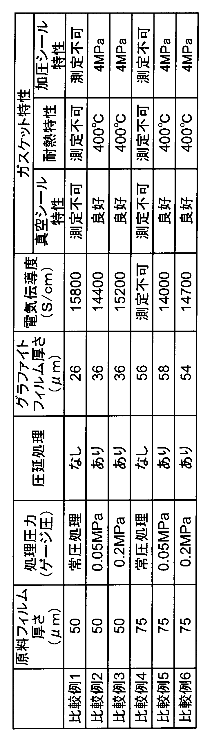
以上の実施例と比較例から、実施例1~7に記載したグラファイトフィルムは、それが高密度・高品質であるか否かを示す指標となる面方向の電気伝導度が高いため、強靭で加圧によっても割れることなくシール特性を発揮できるため、こうしたグラファイトフィルムから得られるガスケット特性は、発泡によって作製したガスケットフィルムの特性(比較例2、3、5、6)を耐熱性で150℃以上、耐圧性で2MPa以上も上回り、極めて優れたガスケット特性である事が分かった。
(実施例8、9)(比較例7~9)
厚さ12.5μmのPMDA/ODA型ポリイミドフィルム((株)カネカ製の市販AHフィルム)を、電気炉を用いて窒素ガス中10℃/minの速度で1000℃まで昇温し、1000℃で1時間保ち、予備熱処理をした。次に得られた炭素化フィルムをグラファイト板に積層してセットし、黒鉛化炉を用いてグラファイト筒と共に20℃/minの速度でそれぞれ、2200℃(比較例7)、2400℃(比較例8)、2600℃(比較例9)、2800℃(実施例8)、3200℃(実施例9)の最高処理温度(最高保持温度)(HTT)まで加熱しグラファイト化した。加熱はアルゴン雰囲気で0.15MPa(ゲージ圧)の加圧下で行い、最高処理温度での保持時間は30分間とした。
厚さ12.5μmのPMDA/ODA型ポリイミドフィルム((株)カネカ製の市販AHフィルム)を、電気炉を用いて窒素ガス中10℃/minの速度で1000℃まで昇温し、1000℃で1時間保ち、予備熱処理をした。次に得られた炭素化フィルムをグラファイト板に積層してセットし、黒鉛化炉を用いてグラファイト筒と共に20℃/minの速度でそれぞれ、2200℃(比較例7)、2400℃(比較例8)、2600℃(比較例9)、2800℃(実施例8)、3200℃(実施例9)の最高処理温度(最高保持温度)(HTT)まで加熱しグラファイト化した。加熱はアルゴン雰囲気で0.15MPa(ゲージ圧)の加圧下で行い、最高処理温度での保持時間は30分間とした。
得られた各グラファイトフィルムの、面方向の電気伝導度、比重を測定し、このフィルムを鏡面に研磨したステンレス板に挟み(直径5cm)、そこに5kg/cm2の荷重を加えて割れが発生するかどうかを試験した。結果を表3に示す。加圧試験は各試料に関して5枚のフィルムを用いて行ない、その内一枚でも割れが発生した場合を使用不可(表3中では×印として記載)とし、全く割れが発生しない場合を使用可とした(表3中では○印として記載)。その結果、最高処理温度が高くなるにつれて、グラファイトフィルムの電気伝導度及び比重が上昇する傾向があり、最高処理温度が2800℃以上で、フィルム面方向の電気伝導度が20000S/cm以上、比重が2.05以上の試料(実施例8、2、9)では割れは発生せずガスケットとして使用できる事が分かった。なお、表3には前記した実施例2の結果も再掲した。
(実施例10)
実施例3で用いたグラファイトガスケット(厚さ4.1μm)5枚を積層し、約20μmのグラファイトガスケットを形成した。このガスケットの真空シール特性、耐熱性、加圧シール特性を実施例1と同じ方法で測定した。その結果真空シール特性は良好で、耐熱特性は600℃、加圧シール特性は6MPa以上であった。この実験から本発明のグラファイトガスケットは多層に積層しても良好な特性を示す事が分かった。
実施例3で用いたグラファイトガスケット(厚さ4.1μm)5枚を積層し、約20μmのグラファイトガスケットを形成した。このガスケットの真空シール特性、耐熱性、加圧シール特性を実施例1と同じ方法で測定した。その結果真空シール特性は良好で、耐熱特性は600℃、加圧シール特性は6MPa以上であった。この実験から本発明のグラファイトガスケットは多層に積層しても良好な特性を示す事が分かった。
(実施例11)
実施例1で用いたグラファイトガスケット(厚さ14.0μm)と銅箔(厚さ10μm)をグラファイトガスケット/銅箔/グラファイトガスケットの順に積層し、950℃、100kg/cm2の圧力でプレス処理して金属芯材を有するガスケットを作製した。その真空シール特性は良好、耐熱性は600℃、加圧シール特性は6MPa以上であり、いずれも良好であった。この結果から本発明のグラファイトガスケットは金属との複合体構造としても良好な特性を示す事が分かった。
実施例1で用いたグラファイトガスケット(厚さ14.0μm)と銅箔(厚さ10μm)をグラファイトガスケット/銅箔/グラファイトガスケットの順に積層し、950℃、100kg/cm2の圧力でプレス処理して金属芯材を有するガスケットを作製した。その真空シール特性は良好、耐熱性は600℃、加圧シール特性は6MPa以上であり、いずれも良好であった。この結果から本発明のグラファイトガスケットは金属との複合体構造としても良好な特性を示す事が分かった。
本発明は強靭性と弾力性を併せ持ち、真空シール性、耐熱性、加圧シール特性の改良されたフィルム状のグラファイトガスケットに関するものである。従って、本発明のグラファイトガスケットは、各種装置の気密性や液密性を保持するのに好適であり、各種プラント、ビル設備、造船等の産業分野で利用できるため、産業上有用である。
1 ステンレス鋼製耐圧チャンバー
2 電気炉
3 フランジ部
4 ボルト・ナット対
5 グラファイトフィルム
6a 平坦部材
6b ステンレス鋼製パイプ
7 圧力ゲージ
8 コック又はバルブ
10 測定装置
2 電気炉
3 フランジ部
4 ボルト・ナット対
5 グラファイトフィルム
6a 平坦部材
6b ステンレス鋼製パイプ
7 圧力ゲージ
8 コック又はバルブ
10 測定装置
Claims (6)
- 厚さ15μm未満、0.5μm以上であり、面方向の電気伝導度が20000S/cm以上であるグラファイトフィルムからなるガスケット。
- 前記グラファイトフィルムの比重が2.05以上、2.26未満である請求項1に記載のガスケット。
- 前記グラファイトフィルムが、高分子フィルムを加圧下、2800℃以上の温度で熱処理して得られたものである請求項1又は2に記載のガスケット。
- 前記高分子フィルムが厚さ25μm未満、0.9μm以上の芳香族ポリイミドである請求項3に記載のガスケット。
- 請求項1~4のいずれかに記載のグラファイトフィルムが複数枚積層された積層ガスケット。
- 金属フィルムからなる芯材の両面に、請求項1~4のいずれかに記載のグラファイトフィルムが単層で、又は積層して配設されている金属芯付きガスケット。
Priority Applications (1)
| Application Number | Priority Date | Filing Date | Title |
|---|---|---|---|
| JP2016568326A JP6660308B2 (ja) | 2015-01-09 | 2015-12-24 | ガスケット |
Applications Claiming Priority (2)
| Application Number | Priority Date | Filing Date | Title |
|---|---|---|---|
| JP2015-003515 | 2015-01-09 | ||
| JP2015003515 | 2015-01-09 |
Publications (1)
| Publication Number | Publication Date |
|---|---|
| WO2016111181A1 true WO2016111181A1 (ja) | 2016-07-14 |
Family
ID=56355881
Family Applications (1)
| Application Number | Title | Priority Date | Filing Date |
|---|---|---|---|
| PCT/JP2015/086033 Ceased WO2016111181A1 (ja) | 2015-01-09 | 2015-12-24 | ガスケット |
Country Status (2)
| Country | Link |
|---|---|
| JP (1) | JP6660308B2 (ja) |
| WO (1) | WO2016111181A1 (ja) |
Citations (6)
| Publication number | Priority date | Publication date | Assignee | Title |
|---|---|---|---|---|
| JPH09199040A (ja) * | 1996-01-12 | 1997-07-31 | Matsushita Electric Ind Co Ltd | プラズマディスプレイパネル、その製造方法およびディスプレイ装置 |
| JP2000046191A (ja) * | 1998-06-27 | 2000-02-18 | Sgl Technik Gmbh | グラファイトフィルムと金属フィルムとからなるパッキン素材 |
| JP2004299919A (ja) * | 2003-03-28 | 2004-10-28 | Kanegafuchi Chem Ind Co Ltd | グラファイト及びその製造方法 |
| JP2013126949A (ja) * | 2013-03-26 | 2013-06-27 | Kaneka Corp | 炭素質フィルムの製造方法 |
| JP2014015391A (ja) * | 2008-01-28 | 2014-01-30 | Kaneka Corp | 炭素質フィルムの製造方法 |
| JP2014220420A (ja) * | 2013-05-09 | 2014-11-20 | 株式会社カネカ | 層間熱接続部材および層間熱接続方法 |
-
2015
- 2015-12-24 WO PCT/JP2015/086033 patent/WO2016111181A1/ja not_active Ceased
- 2015-12-24 JP JP2016568326A patent/JP6660308B2/ja not_active Expired - Fee Related
Patent Citations (6)
| Publication number | Priority date | Publication date | Assignee | Title |
|---|---|---|---|---|
| JPH09199040A (ja) * | 1996-01-12 | 1997-07-31 | Matsushita Electric Ind Co Ltd | プラズマディスプレイパネル、その製造方法およびディスプレイ装置 |
| JP2000046191A (ja) * | 1998-06-27 | 2000-02-18 | Sgl Technik Gmbh | グラファイトフィルムと金属フィルムとからなるパッキン素材 |
| JP2004299919A (ja) * | 2003-03-28 | 2004-10-28 | Kanegafuchi Chem Ind Co Ltd | グラファイト及びその製造方法 |
| JP2014015391A (ja) * | 2008-01-28 | 2014-01-30 | Kaneka Corp | 炭素質フィルムの製造方法 |
| JP2013126949A (ja) * | 2013-03-26 | 2013-06-27 | Kaneka Corp | 炭素質フィルムの製造方法 |
| JP2014220420A (ja) * | 2013-05-09 | 2014-11-20 | 株式会社カネカ | 層間熱接続部材および層間熱接続方法 |
Also Published As
| Publication number | Publication date |
|---|---|
| JP6660308B2 (ja) | 2020-03-11 |
| JPWO2016111181A1 (ja) | 2017-10-12 |
Similar Documents
| Publication | Publication Date | Title |
|---|---|---|
| CN103080005B (zh) | 石墨膜以及石墨膜的制造方法 | |
| JP3152316B2 (ja) | 炭素フィルム及びその製造方法 | |
| CN101827882B (zh) | 具有改良的热稳定性的聚酰亚胺膜 | |
| JP5739954B2 (ja) | 炭素質フィルムの製造方法 | |
| TWI580712B (zh) | 聚亞醯胺膜 | |
| CN111836850B (zh) | 包含基于球形pi的填料的石墨片聚酰亚胺膜、其制造方法及使用其制造的石墨片 | |
| TWI690487B (zh) | 石墨片之製造方法及石墨片用之聚醯亞胺膜 | |
| KR20180060867A (ko) | 압연된 폴리이미드 필름에 기초한 그래파이트 필름 롤의 제조 | |
| US20180049306A1 (en) | Charge stripping film for ion beam | |
| TWI613149B (zh) | 聚醯亞胺膜的製造方法與使用其之石墨膜的製造方法 | |
| JP2004017504A (ja) | 絶縁材付グラファイトフィルム | |
| Zhang et al. | Fabrication of high-temperature aromatic polyamides with ultra-high breakdown strength via complex-assisted chain arrangement | |
| TW201922851A (zh) | 用於製備卷型石墨片的聚醯亞胺膜、石墨片以及電子裝置 | |
| JP4324399B2 (ja) | グラファイトフィルム及びポリイミドフィルム | |
| JP5615627B2 (ja) | グラファイトフィルムの製造方法 | |
| JP4864293B2 (ja) | 高配向グラファイトの製造方法 | |
| KR101992576B1 (ko) | 폴리이미드 피복물의 내열성을 향상시키기 위한 도체 피복용 폴리이미드 바니쉬 및 이로부터 제조된 폴리이미드 피복물 | |
| JP6660308B2 (ja) | ガスケット | |
| WO2019187620A1 (ja) | グラファイトシート及びその製造方法 | |
| KR20240099060A (ko) | 고열전도성 폴리이미드 복합체 필름의 제조방법 및 이를 통하여 제조된 폴리이미드 복합체 필름 | |
| JP3061247B2 (ja) | 黒鉛質フィルム、黒鉛質成形体、その前駆体フィルム及びそれらの製造方法 | |
| JPH0421508A (ja) | グラファイトフィルムの製造方法 | |
| CN110093034A (zh) | 改性的聚酰胺酸及其制备方法、复合膜层的制备方法 | |
| CN112062956A (zh) | 聚酰亚胺弹性凝胶体及其制备方法与应用 | |
| WO2023206762A1 (zh) | 低介电耐电涌清漆及绝缘电线 |
Legal Events
| Date | Code | Title | Description |
|---|---|---|---|
| 121 | Ep: the epo has been informed by wipo that ep was designated in this application |
Ref document number: 15877054 Country of ref document: EP Kind code of ref document: A1 |
|
| ENP | Entry into the national phase |
Ref document number: 2016568326 Country of ref document: JP Kind code of ref document: A |
|
| NENP | Non-entry into the national phase |
Ref country code: DE |
|
| 122 | Ep: pct application non-entry in european phase |
Ref document number: 15877054 Country of ref document: EP Kind code of ref document: A1 |