WO2016111022A1 - セラミックコート層付きエンジン部材及びセラミックコート層付きエンジン部材の製造方法 - Google Patents
セラミックコート層付きエンジン部材及びセラミックコート層付きエンジン部材の製造方法 Download PDFInfo
- Publication number
- WO2016111022A1 WO2016111022A1 PCT/JP2015/064477 JP2015064477W WO2016111022A1 WO 2016111022 A1 WO2016111022 A1 WO 2016111022A1 JP 2015064477 W JP2015064477 W JP 2015064477W WO 2016111022 A1 WO2016111022 A1 WO 2016111022A1
- Authority
- WO
- WIPO (PCT)
- Prior art keywords
- coat layer
- ceramic coat
- ceramic
- engine
- engine member
- Prior art date
- Legal status (The legal status is an assumption and is not a legal conclusion. Google has not performed a legal analysis and makes no representation as to the accuracy of the status listed.)
- Ceased
Links
Images


Classifications
-
- C—CHEMISTRY; METALLURGY
- C23—COATING METALLIC MATERIAL; COATING MATERIAL WITH METALLIC MATERIAL; CHEMICAL SURFACE TREATMENT; DIFFUSION TREATMENT OF METALLIC MATERIAL; COATING BY VACUUM EVAPORATION, BY SPUTTERING, BY ION IMPLANTATION OR BY CHEMICAL VAPOUR DEPOSITION, IN GENERAL; INHIBITING CORROSION OF METALLIC MATERIAL OR INCRUSTATION IN GENERAL
- C23C—COATING METALLIC MATERIAL; COATING MATERIAL WITH METALLIC MATERIAL; SURFACE TREATMENT OF METALLIC MATERIAL BY DIFFUSION INTO THE SURFACE, BY CHEMICAL CONVERSION OR SUBSTITUTION; COATING BY VACUUM EVAPORATION, BY SPUTTERING, BY ION IMPLANTATION OR BY CHEMICAL VAPOUR DEPOSITION, IN GENERAL
- C23C24/00—Coating starting from inorganic powder
- C23C24/08—Coating starting from inorganic powder by application of heat or pressure and heat
-
- F—MECHANICAL ENGINEERING; LIGHTING; HEATING; WEAPONS; BLASTING
- F01—MACHINES OR ENGINES IN GENERAL; ENGINE PLANTS IN GENERAL; STEAM ENGINES
- F01L—CYCLICALLY OPERATING VALVES FOR MACHINES OR ENGINES
- F01L3/00—Lift-valve, i.e. cut-off apparatus with closure members having at least a component of their opening and closing motion perpendicular to the closing faces; Parts or accessories thereof
- F01L3/02—Selecting particular materials for valve-members or valve-seats; Valve-members or valve-seats composed of two or more materials
-
- F—MECHANICAL ENGINEERING; LIGHTING; HEATING; WEAPONS; BLASTING
- F01—MACHINES OR ENGINES IN GENERAL; ENGINE PLANTS IN GENERAL; STEAM ENGINES
- F01L—CYCLICALLY OPERATING VALVES FOR MACHINES OR ENGINES
- F01L3/00—Lift-valve, i.e. cut-off apparatus with closure members having at least a component of their opening and closing motion perpendicular to the closing faces; Parts or accessories thereof
- F01L3/02—Selecting particular materials for valve-members or valve-seats; Valve-members or valve-seats composed of two or more materials
- F01L3/04—Coated valve members or valve-seats
-
- F—MECHANICAL ENGINEERING; LIGHTING; HEATING; WEAPONS; BLASTING
- F02—COMBUSTION ENGINES; HOT-GAS OR COMBUSTION-PRODUCT ENGINE PLANTS
- F02F—CYLINDERS, PISTONS OR CASINGS, FOR COMBUSTION ENGINES; ARRANGEMENTS OF SEALINGS IN COMBUSTION ENGINES
- F02F1/00—Cylinders; Cylinder heads
-
- F—MECHANICAL ENGINEERING; LIGHTING; HEATING; WEAPONS; BLASTING
- F02—COMBUSTION ENGINES; HOT-GAS OR COMBUSTION-PRODUCT ENGINE PLANTS
- F02F—CYLINDERS, PISTONS OR CASINGS, FOR COMBUSTION ENGINES; ARRANGEMENTS OF SEALINGS IN COMBUSTION ENGINES
- F02F3/00—Pistons
- F02F3/10—Pistons having surface coverings
Definitions
- the present invention relates to an engine member with a ceramic coat layer and a method for producing an engine member with a ceramic coat layer.
- Patent Document 1 discloses that a metal base material includes an amorphous inorganic material and a crystalline inorganic material. A technique for applying a paint containing a pore former and applying a heat insulating coating to a metal substrate is disclosed.
- the above technology is a technology for heat insulation of the exhaust pipe, and the properties required for the heat insulating coat (surface coating layer) are functions such as heat insulation, thermal conductivity, prevention of peeling, etc. If it exists, it is said that it is suitable as a surface coating layer.
- a wide range is set for the thickness of the surface coating layer, the average pore diameter of the pores formed in the surface coating layer, the porosity, and the like.
- the thickness of the coat layer is reduced.
- the heat capacity of the coat layer increases.
- the temperature of the heated coat layer does not decrease easily, and the inhaled air-fuel mixture may be heated. If the intake air-fuel mixture is warmed before being compressed, the air-fuel mixture expands in volume and cannot be sufficiently compressed during compression, and when ignited in that state, abnormal combustion occurs and knocking occurs.
- the present invention has been made in view of the above-described problems, and has an engine with a ceramic coat layer that can improve heat insulation without causing knocking to an engine member that faces the engine combustion chamber.
- An object is to provide a member.
- an engine member with a ceramic coat layer of the present invention is provided.
- the ceramic coat layer has a thickness of 50 to 200 ⁇ m, Pores are formed in the ceramic coat layer, the average pore diameter is 0.5 to 15 ⁇ m, and the porosity of the ceramic coat layer is 10 to 60%.
- the thickness of the ceramic coat layer is as thin as 200 ⁇ m or less, the heat capacity of the ceramic coat layer is small. Therefore, since the temperature of the ceramic coat layer is appropriately reduced, the intake air-fuel mixture is prevented from being heated by the heat of the ceramic coat layer, and knocking is prevented. Further, as the thickness of the ceramic coat layer is reduced, the average pore diameter of the pores formed in the ceramic coat layer is controlled to be fine pores of 0.5 to 15 ⁇ m. When the average pore diameter of the pores is about this level, the pores exist as independent pores in the ceramic coat layer, and effectively function as a structure that enhances heat insulation. Further, since the porosity is 10 to 60%, sufficient heat insulation is maintained.
- carbon particles are preferably present in the ceramic coat layer. If carbon particles are present in the ceramic coat layer, crack propagation is hindered by the carbon particles, so that cracks due to thermal shock are less likely to occur in the ceramic coat layer.
- the amount of the carbon particles present in the ceramic coat layer is 0.005 to 1 part by weight with respect to 100 parts by weight of the entire ceramic coat layer. desirable. When the amount of the carbon particles is within the above range, the progress of cracks can be more effectively inhibited.
- the engine member with a ceramic coat layer of the present invention it is desirable that no air hole having a pore diameter exceeding 45 ⁇ m exists in the ceramic coat layer. If there are no air holes, the progress of cracks is likely to be hindered, so that cracks due to thermal shock are less likely to occur in the ceramic coat layer. Further, since the wall thickness between the pores can be increased as compared with the case where the air holes exist, the strength of the heat insulating film as a whole increases. Moreover, since the pore diameter is small, convective heat transfer in the pores is suppressed, and the heat insulation effect is improved.
- the ceramic coat layer is formed on the umbrella surface of the engine valve.
- the umbrella surface of the engine valve faces the engine combustion chamber and is a portion that is frequently exposed to high temperatures associated with the combustion of fuel in the combustion chamber. If this part is insulated, heat loss is effectively reduced.
- the ceramic coat layer is formed on the back surface of the umbrella of the engine valve.
- the umbrella rear surface of the engine valve is a surface that faces the engine combustion chamber when the valve is in an open state, and is a portion that is frequently exposed to high temperatures associated with combustion of fuel in the combustion chamber. If this part is insulated, heat loss is effectively reduced.
- the ceramic coat layer is preferably made of an amorphous inorganic material and a crystalline inorganic material.
- the amorphous inorganic material functions as a glass layer that covers the engine member.
- the crystalline inorganic material plays a role as a member for improving heat resistance.
- the presence of the amorphous inorganic material and the crystalline inorganic material in the ceramic coat layer increases the strength of the ceramic coat layer.
- the amorphous inorganic material is desirably a low softening point glass having a softening point of 300 to 1000 ° C.
- the amorphous inorganic material is softened and melted by heating at a temperature exceeding the softening point, and spreads on the surface of the engine member to form a ceramic coat layer.
- the crystalline inorganic material is preferably made of at least one selected from the group consisting of alumina, zirconia, yttria, calcia, magnesia, ceria, and hafnia.
- the ceramic coat layer containing the crystalline inorganic material having excellent heat resistance performance is improved in heat resistance. Also, the heat insulation performance is improved.
- the crystalline inorganic material is preferably an oxide of at least one metal selected from manganese, iron, cobalt, copper, chromium, and nickel.
- the method for producing an engine member with a ceramic coat layer of the present invention comprises 0.01 to 10 parts per 100 parts by weight of the ceramic raw material for forming the ceramic coat layer on the surface facing the engine combustion chamber of the engine member and the ceramic raw material.
- a heat treatment process in which the engine member on which the coating layer is formed is subjected to heat treatment, and carbon particles are vaporized in the coating layer to form a ceramic coat layer and pores in the ceramic coat layer. It is characterized by.
- the ceramic raw material is preferably composed of an amorphous inorganic material and a crystalline inorganic material.
- the heat treatment is performed at a temperature equal to or higher than the softening point of the amorphous inorganic material, carbon particles are gasified in the softened amorphous inorganic material and become pores in the softened amorphous inorganic material.
- gasification is completed before the amorphous inorganic material is softened, the gas escapes between the particles of the amorphous inorganic material, and it is difficult to form pores.
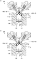
- FIG. 1A and FIG. 1B are cross-sectional views schematically showing an example of the structure of an engine combustion chamber in which the engine member with a ceramic coat layer of the present invention is used.
- 2 (a) and 2 (b) are cross-sectional views schematically showing an example of a surface facing the engine combustion chamber when the engine valve is open.
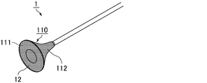
- FIG. 3 is a perspective view schematically showing an engine valve as an example of an engine member with a ceramic coat layer according to the present invention.
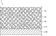
- 4 is a partially cut cross-sectional view of the engine valve shown in FIG.
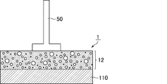
- FIG. 5 is a schematic cross-sectional view of a sample for coating layer strength measurement.
- FIG. 6 is an external view of a tensile test by a tensile tester.
- the engine member with a ceramic coat layer and the method for producing the engine member with a ceramic coat layer of the present invention will be specifically described.
- the present invention is not limited to the following configurations, and can be applied with appropriate modifications without departing from the scope of the present invention.
- the present invention also includes a combination of two or more desirable configurations of the present invention described below.
- the engine member with a ceramic coat layer of the present invention An engine member with a ceramic coat layer in which a ceramic coat layer made of a ceramic raw material is formed on a surface facing an engine combustion chamber,
- the ceramic coat layer has a thickness of 50 to 200 ⁇ m, Pores are formed in the ceramic coat layer, the average pore diameter is 0.5 to 15 ⁇ m, and the porosity of the ceramic coat layer is 10 to 60%.
- FIG. 1A and FIG. 1B are cross-sectional views schematically showing an example of the structure of an engine combustion chamber in which the engine member with a ceramic coat layer of the present invention is used.
- an engine valve 110 including an intake in-valve 110 a and an exhaust exhaust valve 110 b is provided on an upper portion of a cylindrical cylinder 120, and a piston 130 is provided inside the cylinder 120.
- the engine member with a ceramic coat layer of the present invention is provided on the surface of the engine combustion chamber facing the engine combustion chamber.
- the surfaces facing the engine combustion chamber include the umbrella surface 111 of the engine valve 110 (the umbrella surface 111a of the in-valve 110a and the umbrella surface 111b of the exhaust valve 110b) in the engine combustion chamber 100 shown in FIGS. 1 (a) and 1 (b).
- the inner wall 121 of the cylinder 120 and the upper surface 131 of the piston 130 are included.
- FIG. 1 (b) the position of the surface facing the engine combustion chamber is indicated by hatching.
- FIGS. 2 (a) and 2 (b) are cross-sectional views schematically showing an example of a surface facing the engine combustion chamber when the engine valve is open.
- FIG. 2A shows a state in which the in-valve 110a is open and the umbrella back surface 112a faces the engine combustion chamber.
- FIG. 2B shows the exhaust valve 110b in an open state. The state where the umbrella back surface 112b faces the engine combustion chamber is shown.
- FIGS. 2A and 2B the position of the surface facing the engine combustion chamber is indicated by hatching in the same manner as in FIG. 1B.
- each member such as an engine valve, a cylinder, and a piston constituting the surface facing the engine combustion chamber is not particularly limited, but a material conventionally used as a material of each member can be applied.
- a material conventionally used as a material of each member can be applied.
- stainless steel, heat resistant steel, aluminum, aluminum alloy, iron, inconel, hastelloy, invar, and the like can be given.
- various cast products for example, cast iron, cast steel, carbon steel, etc.
- An example of the material of the engine valve (the umbrella surface and the back of the umbrella of the engine valve) is heat resistant steel (SUH).
- martensitic heat resistant steel (SUH3, SUH11, etc.), austenitic heat resistant steel (SUH35, etc.), ferritic heat resistant steel (SUH446, etc.) and the like can be mentioned.
- Ni-based heat-resistant alloys such as Inconel (NCF751 etc.) are also included.
- the material of the cylinder (cylinder inner wall) include cast iron and aluminum alloy.
- the material of the piston (the upper surface of the piston) include cast iron, aluminum alloy, and titanium alloy.
- the aluminum alloy used for the cylinder and piston is not particularly limited.
- pure aluminum 1000 series
- Al-Cu alloy 2000 series
- Al-Mn alloy 3000 series
- Al-Si alloy 4000 series
- Al-Mg based alloys 5000 series
- Al-Mg-Si based alloys 6000 series
- Al-Zn-Mg based alloys 7000 series
- the composition of the alloy is not particularly limited.
- the surface of the aluminum alloy may be anodized.
- the engine member with a ceramic coat layer of the present invention is preferably used as an engine valve, and more preferably used as an in-valve. And it is more preferable that it is a member by which the ceramic coat layer was provided in the umbrella surface and / or umbrella back surface of an engine valve (preferably in-valve).
- the ceramic coat layer is provided on the umbrella surface of the engine valve, since the heat capacity of the ceramic coat layer is small, it is possible to effectively prevent the intake air-fuel mixture from being warmed and to prevent the occurrence of knocking. And since heat insulation is hold
- the surface of the engine member may be subjected to a sandblasting treatment or a roughening treatment with a chemical.
- the surface roughness Rz JIS of the surface of the engine member formed by the roughening treatment is desirably 0.3 to 20 ⁇ m.
- the surface roughness Rz JIS described above is a ten-point average roughness defined by JIS B 0601 (2001). If the surface roughness Rz JIS of the surface of the engine member is less than 0.3 ⁇ m, the surface area of the surface of the engine member becomes small, and it becomes difficult to obtain sufficient adhesion between the surface of the engine member and the ceramic coat layer. On the other hand, when the surface roughness Rz JIS of the surface of the engine member exceeds 20 ⁇ m, it becomes difficult to form a ceramic coat layer on the surface of the engine member.
- the surface roughness Rz JIS of the surface of the engine member can be measured according to JIS B 0601 (2001) using Handy Surf E-35B manufactured by Tokyo Seimitsu. The measurement is performed at 25 ° C. and atmospheric pressure.
- FIG. 3 is a perspective view schematically showing an engine valve as an example of an engine member with a ceramic coat layer according to the present invention.
- 4 is a partially cut cross-sectional view of the engine valve shown in FIG.
- the engine member 1 with a ceramic coat layer shown in FIG. 3 is formed by forming the ceramic coat layer 12 on the umbrella surface 111 and the umbrella back surface 112 of the engine valve 110.
- FIG. 4 shows a cross section including a cross section of the ceramic coat layer and a cross section on the umbrella surface side of the engine valve.
- the ceramic coat layer with which the engine member with a ceramic coat layer of this invention is provided is demonstrated.
- the ceramic coat layer 12 is made of a ceramic raw material, and examples of the ceramic raw material include an amorphous inorganic material.
- the amorphous inorganic material is preferably made of glass, and more preferably low-softening point glass having a softening point of 300 to 1000 ° C.
- Examples of the low softening point glass having a softening point of 300 to 1000 ° C. include SiO 2 —B 2 O 3 —ZnO glass, SiO 2 —B 2 O 3 —Bi 2 O 3 glass, and SiO 2 —PbO glass.
- the softening point should be measured, for example, using a glass automatic softening point / strain point measuring device (SSPM-31) manufactured by Opt Corp., based on the method specified in JIS R 3103-1: 2001. Can do. The measurement is performed at atmospheric pressure.
- SSPM-31 glass automatic softening point / strain point measuring device manufactured by Opt Corp.
- the ceramic coat layer is preferably a layer made of a crystalline inorganic material in addition to an amorphous inorganic material.
- the crystalline inorganic material is preferably made of at least one selected from the group consisting of alumina, zirconia, yttria, calcia, magnesia, ceria, and hafnia.
- the crystalline inorganic material is also preferably an oxide of at least one metal selected from manganese, iron, cobalt, copper, chromium, and nickel.
- FIG. 4 shows a layer in which the amorphous inorganic material and the crystalline inorganic material contained in the ceramic coat layer 12 are mixed without being distinguished.
- the content of the crystalline inorganic material contained in the ceramic coat layer is preferably 1 to 50% by weight and more preferably 10 to 45% by weight with respect to the weight of the ceramic coat layer.
- the ceramic coat layer has a thickness of 50 to 200 ⁇ m.
- the thickness of the ceramic coat layer can be measured by cutting the engine member with the ceramic coat layer and observing the cross section with an SEM or the like.
- the heat capacity of the ceramic coat layer is small, so that it is possible to effectively prevent the intake air-fuel mixture from being warmed and to prevent the occurrence of knocking.
- heat insulation is hold
- pores 13 are formed.
- the average pore diameter of the pores formed in the ceramic coat layer is 0.5 to 15 ⁇ m.
- the average pore diameter is preferably 3 to 13 ⁇ m, more preferably 5 to 10 ⁇ m.
- the pores are present as independent pores in the ceramic coat layer, and function effectively as a structure that enhances heat insulation.
- the porosity of the ceramic coat layer is 10 to 60%.
- the porosity is preferably 15 to 50%, more preferably 20 to 40%. When the porosity is 10 to 60%, sufficient heat insulation by the pores is maintained.
- the average pore diameter of the pores can be measured by cutting an engine member with a ceramic coat layer and observing the cross section using an SEM or the like. Specifically, the SEM image is taken so that the whole area of the ceramic coat layer in the thickness direction is included, the photographed image is divided into nine regions, and the pore diameters of all pores present in each compartment are measured. And an average pore diameter is obtained by calculating
- the diameter of the pores is the diameter corresponding to the projected area circle (Haywood diameter).
- the porosity of the ceramic coat layer is calculated by calculating the bulk density from the thickness of the ceramic coat layer and the thickness of the ceramic coat layer measured with a film thickness meter (dual scope), and calculating the ratio of the true density calculated by the pycnometer. Then, the value obtained by subtracting the value from 1 can be calculated as the porosity.
- the SEM measurement magnification is 1000 times when the thickness of the ceramic coat layer is less than 50 to 100 ⁇ m, and 500 times when the thickness of the ceramic coat layer is 100 to 200 ⁇ m.
- no air hole having a pore diameter exceeding 45 ⁇ m exists in the ceramic coat layer.
- the presence or absence of air holes can be determined by measuring the pore diameter of the pores present in the SEM image and confirming that there are no pores exceeding 45 ⁇ m.
- carbon particles are preferably present in the ceramic coat layer.
- FIG. 4 shows a state in which the carbon particles 14 are present in the ceramic coat layer 12.
- the amount of carbon particles is preferably 0.005 to 1 part by weight, more preferably 0.008 to 1 part by weight, based on 100 parts by weight of the entire ceramic coat layer.
- the amount of carbon particles is measured by peeling the ceramic coat layer, melting the ceramic raw material constituting the ceramic coat layer, filtering the solution with a filter, and quantifying the remaining carbon particles by the combustion infrared absorption method. be able to.
- the ceramic raw material is glass, it can be melted using hydrochloric acid or hydrofluoric acid.
- the ceramic raw material is melted by the above method and the carbon particles do not remain after the solution is filtered, it is presumed that the carbon particles are not contained in the ceramic coat layer.
- the carbon particles are preferably particles that can be vaporized by heat treatment to form pores, and are blended as a material for forming pores in the ceramic coat layer in the process of manufacturing an engine member with a ceramic coat layer. Material. A part of the blended carbon particles remains in the ceramic coat layer. If a part of the carbon particles is left without being vaporized, the progress of cracks is inhibited by the carbon particles, so that the ceramic coat layer is less likely to be cracked by thermal shock.
- carbon particles graphite particles are preferable, and specifically, ET-10 manufactured by Ibiden Co., Ltd., pitch, coke and the like are preferably used.
- the average particle size of the carbon particles is preferably 0.1 to 30 ⁇ m.
- the thermal conductivity of the ceramic coat layer at room temperature is preferably 0.1 to 1.0 W / m ⁇ K. If the thermal conductivity is less than 0.1 W / m ⁇ K, the porosity required to achieve the above thermal conductivity is increased, so that the mechanical strength of the formed ceramic coat layer may be excessively lowered. is there. On the other hand, if the thermal conductivity exceeds 1.0 W / m ⁇ K, there is a problem that a sufficient heat insulating effect cannot be obtained. In order to obtain a desired heat insulation effect, it is necessary to increase the thickness of the ceramic coat layer, so that the heat capacity of the ceramic coat layer is increased.
- the thermal conductivity is measured based on JISR 1611 (2010) using a laser flash device (thermal constant measuring device: NETZSCH LFA457 Microflash). The measurement is performed at 25 ° C. and atmospheric pressure.
- the film strength of the ceramic coat layer is preferably 15 to 50 MPa.
- the film strength can be measured by the coating layer strength measurement procedure described in the Examples section. When carbon particles are present in the ceramic coat layer, the film strength of the ceramic coat layer can be increased. The measurement is performed at 25 ° C. and atmospheric pressure.
- the specific heat of the ceramic coat layer is preferably 650 to 900 J / kgK. Specific heat can be measured by DSC (differential scanning calorimetry).
- the heat capacity (heat capacity per unit area) of the ceramic coat layer is preferably 50 to 600 [J / m 2 ⁇ K]. The heat capacity of the ceramic coat layer can be calculated by multiplying the specific heat, density and film thickness of the ceramic coat layer.
- the method for producing an engine member with a ceramic coat layer of the present invention is as follows. By applying to the surface of the engine member facing the engine combustion chamber a ceramic raw material for forming a ceramic coat layer and a raw material mixture comprising 0.01 to 10 parts by weight of carbon particles with respect to 100 parts by weight of the ceramic raw material.
- a coating layer forming step of forming a coating layer for forming a ceramic coat layer A heat treatment process in which the engine member on which the coating layer is formed is subjected to heat treatment, and carbon particles are vaporized in the coating layer to form a ceramic coat layer and pores in the ceramic coat layer. It is characterized by.
- an engine member is prepared as a material for an engine member with a ceramic coat layer.
- a cleaning process to remove impurities on a surface facing the engine combustion chamber, which is a surface on which the ceramic coat layer is formed.
- the cleaning treatment is not particularly limited, and a conventionally known cleaning treatment method can be used. Specifically, for example, a method of performing ultrasonic cleaning in an alcohol solvent can be used.
- the surface facing the engine combustion chamber may be roughened.
- the roughening treatment include sand blast treatment, etching treatment, and high temperature oxidation treatment. These may be used alone or in combination of two or more. You may perform a washing process after this roughening process. In addition, it is preferable to perform a roughening process ahead of the coating layer formation process mentioned later.
- the surface facing the engine combustion chamber may be anodized as necessary.
- an alumite layer can be formed on the surface facing the engine combustion chamber, and the adhesion between the engine member and the ceramic coat layer can be further improved.
- alumite treatment is performed on a part of the engine member, it is preferable to protect the portion not subjected to the alumite treatment by attaching a masking tape or the like.
- an alkaline bath or a non-aqueous bath such as formamide and boric acid can be used in addition to the acidic bath.
- Acid baths include sulfuric acid, phosphoric acid, chromic acid, oxalic acid, sulfosalicylic acid, pyrophosphoric acid, sulfamic acid, phosphomolybdic acid, boric acid, malonic acid, succinic acid, maleic acid, citric acid, tartaric acid, phthalic acid, itacone
- An aqueous solution in which one or two or more acids, malic acid, glycolic acid and the like are dissolved can be used.
- dissolved 1 type, or 2 or more types of sodium hydroxide, potassium hydroxide, sodium carbonate, potassium phosphate, ammonia water etc. can be used as an alkaline bath. It is preferable to form an alumite layer of 0.2 to 100 ⁇ m on the surface facing the engine combustion chamber by the alumite treatment.
- (B) Coating layer forming step (b-1) Raw material mixture preparation step Subsequently, a raw material mixture for forming a coating layer is prepared.
- a raw material mixture is obtained by mixing 0.01 to 10 parts by weight of carbon particles with respect to 100 parts by weight of ceramic raw material and ceramic raw material.
- the raw material mixture can be obtained, for example, by mixing ceramic raw materials, carbon particles, and water and wet-mixing them with a ball mill or the like.
- the order and combination of mixing the above three components are not particularly limited.
- the ceramic raw material and water may be mixed first, and then carbon particles may be added, or water may be added after mixing the ceramic raw material and carbon particles.
- the ceramic raw material, carbon particles, and water may be mixed at a time.
- the carbon particles contained in the raw material mixture burn in the subsequent firing step to generate CO and CO 2 to form pores. That is, the carbon particles function as a pore forming agent. Moreover, it is preferable that a part of carbon particle remains in a ceramic coat layer after a baking process.
- the mixing ratio of the ceramic raw material and water is not particularly limited, but about 100 parts by weight of water is preferable with respect to 100 parts by weight of the ceramic raw material. This is because, when the ceramic raw material and water are mixed in such a weight ratio, the viscosity is suitable for application to the engine member. Moreover, you may mix
- the dispersion medium for example, water or an organic solvent such as methanol, ethanol, or acetone can be used.
- the content of the dispersion medium in the raw material mixture is not particularly limited.
- the dispersion medium is preferably 50 to 150 parts by weight with respect to 100 parts by weight of the ceramic raw material. This is because, by blending the dispersion medium at such a ratio, the viscosity of the raw material mixture becomes a viscosity suitable for application to the engine member.
- the organic binder include polyvinyl alcohol, methyl cellulose, ethyl cellulose, carboxymethyl cellulose, and the like. These may be used alone or in combination of two or more. Further, a dispersion medium and an organic binder may be used in combination.
- the content of carbon particles in the raw material mixture is 0.01 to 10 parts by weight with respect to 100 parts by weight of the ceramic raw material.
- the carbon particle content is preferably 0.05 to 8 parts by weight, and more preferably 0.08 to 5 parts by weight.
- a crystalline inorganic material may be further added to the raw material mixture.
- the timing of adding the crystalline inorganic material is not particularly limited. For example, before mixing the ceramic raw material, the carbon particles, and the water, the ceramic raw material and the crystalline inorganic material are mixed. You may have the process of mixing. Since the crystalline inorganic material is the same as that described in the description of the engine member with a ceramic coat layer of the present invention, the description thereof is omitted here.
- a coating layer for forming a ceramic coating layer is formed by coating a raw material mixture for forming a ceramic coating layer on the surface facing the engine combustion chamber.
- the thickness of the coating layer is not particularly limited, but it is preferably 50 to 200 ⁇ m, and preferably a thickness capable of forming a ceramic coat layer having a thickness of 50 to 200 ⁇ m.
- the thickness of the coating layer is less than 50 ⁇ m, the formed ceramic coat layer is too thin, and the engine member with the ceramic coat layer may not be able to exhibit sufficient heat insulation.
- the thickness of the coating layer exceeds 200 ⁇ m, the heat capacity of the formed ceramic coating layer increases, which may cause knocking.
- Examples of the method for forming the coating layer on the surface facing the engine combustion chamber include spray coating, electrostatic coating, ink jet, spin coating, transfer using a stamp or roller, brush coating, and the like.
- (C) Heat treatment step Next, heat treatment is performed on the engine member on which the coating layer is formed, and carbon particles are vaporized in the coating layer to form a ceramic coat layer and pores in the ceramic coat layer.
- a heat treatment process is performed.
- the engine member on which the coating layer is formed may be dried at about 50 to 150 ° C.
- the conditions of the heat treatment process can be arbitrarily set in consideration of the material of the engine member, etc., but 400 to 1100 ° C. when the material of the engine member is stainless steel and 400 to 1100 when it is heat resistant steel.
- heat treatment is preferably performed at 300 to 650 ° C.
- the heating time is preferably 3 to 120 minutes.
- heat processing temperature shall be more than the softening point of a ceramic raw material.
- the heating temperature By setting the heating temperature to a temperature equal to or higher than the softening point of the ceramic raw material, the applied ceramic raw material is softened and melted, and the formed ceramic coat layer and the engine member are firmly adhered. At this time, the carbon particles contained in the raw material mixture are dispersed in the softened ceramic raw material, and pores are formed by causing thermal decomposition. Further, when the pores are exposed on the surface of the ceramic coat layer during the heat treatment step, the ceramic raw material forming the ceramic coat layer is softened, so that the portion where the pores are exposed can be closed quickly. Therefore, pores are not exposed on the surface of the fired ceramic coat layer, and a ceramic coat layer with high flatness (low surface roughness) can be obtained.
- the heat treatment process conditions are adjusted based on the blended amount of carbon particles, the target pore diameter, porosity, etc., and heat treatment is performed to such an extent that some of the carbon particles do not vaporize. It is preferable to perform heat treatment to such an extent that it remains in the ceramic coat layer. By preventing the heat treatment from being performed excessively, it is possible to prevent the generation of atmospheric pores having a pore diameter exceeding 45 ⁇ m, and it is possible to form a ceramic coat layer in which the pores are uniformly dispersed.
- the effect of the engine member with a ceramic coat layer of this invention is enumerated.
- the thickness of the ceramic coat layer is as thin as 200 ⁇ m or less, the heat capacity of the ceramic coat layer is small. Therefore, since the temperature of the ceramic coat layer is appropriately reduced, the intake air-fuel mixture is prevented from being heated by the heat of the ceramic coat layer, and knocking is prevented. Further, as the thickness of the ceramic coat layer is reduced, the average pore diameter of the pores formed in the ceramic coat layer is controlled to be fine pores of 0.5 to 15 ⁇ m. When the average pore diameter of the pores is about this level, the pores exist as independent pores in the ceramic coat layer, and effectively function as a structure that enhances heat insulation. Further, since the porosity is 10 to 60%, sufficient heat insulation is maintained.
- this surface is a surface that faces the engine combustion chamber when the valve is open. And since it is a site
- Example 1 Preparation of engine member An engine valve (in-valve) made of stainless steel (SUS430) was prepared as an engine member, and ultrasonic cleaning was performed in an alcohol solvent. Subsequently, sandblasting was performed to roughen the surface of the umbrella that faces the engine combustion chamber. The sandblast treatment was performed for 10 minutes using # 100 Al 2 O 3 abrasive grains.
- Example 2 A ceramic coat layer having a thickness of 200 ⁇ m was formed in the same manner as in Example 1 except that the blending amount of the carbon particles was changed to 0.46 parts by weight and the coating amount of the raw material mixture was changed. Manufactured.
- Handy Surf E-35B surface roughness measuring machine
- Example 4 A ceramic coat layer having a thickness of 50 ⁇ m was formed in the same manner as in Example 1 except that the blending amount of the carbon particles was changed to 1.15 parts by weight and the coating amount of the raw material mixture was changed. Manufactured.
- Example 5 A 150 ⁇ m thick ceramic coat layer was formed in the same manner as in Example 1 except that the heat treatment conditions in the firing furnace were changed to 780 ° C. for 50 minutes, and the coating amount of the raw material mixture was changed, and the ceramic coat layer was attached. An engine member was manufactured.
- Example 6 A ceramic coating layer having a thickness of 200 ⁇ m was formed in the same manner as in Example 1 except that the blending amount of the carbon particles was changed to 3.34 parts by weight and the coating amount of the raw material mixture was changed. Manufactured.
- Example 7 A ceramic coat layer having a thickness of 100 ⁇ m is formed in the same manner as in Example 1 except that the amount of carbon particles is changed to 0.02 parts by weight and the heat treatment conditions in the baking furnace are changed to 800 ° C. and 100 minutes. And the engine member with a ceramic coat layer was manufactured.
- Example 8 A ceramic coating layer having a thickness of 200 ⁇ m was formed in the same manner as in Example 1 except that the blending amount of the carbon particles was changed to 2.3 parts by weight and the coating amount of the raw material mixture was changed. Manufactured.
- Example 1 A 200 ⁇ m thick ceramic coat layer was formed in the same manner as in Example 1 except that the amount of carbon particles was changed to 0.0023 parts by weight and the heat treatment conditions in the firing furnace were changed to 820 ° C. and 120 minutes. And the engine member with a ceramic coat layer was manufactured.
- Example 2 An engine member with a ceramic coat layer was formed by forming a ceramic coat layer having a thickness of 200 ⁇ m in the same manner as in Example 3 except that carbon particles were not blended and the heat treatment conditions in the firing furnace were changed to 700 ° C. and 120 minutes. Manufactured.
- the bulk density was calculated from the thickness of the ceramic coat layer, the ratio with the true density calculated with a pycnometer was calculated, and the value was subtracted from 1, and the value obtained as a percentage was calculated as the porosity of the ceramic coat layer.
- the surface of the engine member with a ceramic coat layer manufactured in each Example and each comparative example was cut
- the average pore size was measured by measuring the size (pore size) of all pores having a pore size of 0.1 ⁇ m or more and averaging the obtained numerical values. The results are shown in Table 1.
- the amount of carbon particles is measured by peeling the ceramic coat layer, melting the ceramic raw material constituting the ceramic coat layer with hydrochloric acid, filtering the solution with a filter, and quantifying the remaining carbon particles by the combustion infrared absorption method Went by.
- the measurement by the combustion infrared absorption method was performed by using a carbon sulfur analyzer (CSLS600 manufactured by LECO) as a measuring device.
- CSLS600 carbon sulfur analyzer
- the glass component SiO 2 constituting the ceramic coat layer was removed by heating in the presence of HF.
- oxygen gas was allowed to flow and carbon particles were burned in a high-frequency induction heating furnace in the presence of high-purity iron.
- the amount of carbon particles is shown as parts by weight with respect to 100 parts by weight of the entire ceramic coat layer. The results are shown in Table 1.
- FIG. 5 is a schematic cross-sectional view of a sample for coating layer strength measurement.
- the stud pin 50 was attached to the surface of the ceramic coat layer 12 of the engine member 1 with the ceramic coat layer using a clip, and was fixed by heating at 150 ° C. for 1 hour to prepare a measurement sample.
- P / N901106 (2.7mm epoxy adhesive Al stud pin made by QUAD GROUP) was used.
- FIG. 6 is an external view of a tensile test by a tensile tester.
- the tensile tester 500 Using the tensile tester 500, the stud pin 50 fixed to the ceramic coat layer 12 was pulled. The coating layer strength was calculated from the maximum value of the force applied until the ceramic coating layer 12 in contact with the stud pin 50 peeled from the engine valve 110 and the cross-sectional area of the stud pin 50.
- As the tensile tester 500 an autograph AGS50A manufactured by Shimadzu Corporation was used. The measurement was performed at 25 ° C. and atmospheric pressure.
- the raw material mixture prepared in the coating layer forming step in the examples and comparative examples was applied to a SUS plate, and heat-treated under the same conditions as in the examples and comparative examples, thereby producing test pieces for measuring thermal conductivity. .
- the thickness of the test piece for measuring thermal conductivity was set to be the same as in each example and comparative example.
- the specific heat of the ceramic coat layer was measured by a DSC method (differential scanning calorimetry) using a Rigaku high-sensitivity differential scanning calorimeter Thermo plus EVO2.
- the density of the ceramic coat layer was measured with a Pycnometer Pentapyc 5200e manufactured by Cantachrome Instruments Japan Co., Ltd., and the film thickness was measured with a dual scope (manufactured by Fisher Instruments Co., Ltd., dual scope MP40).
- the heat capacity was calculated by multiplying the specific heat, density, and film thickness.
- the heat capacity obtained here is the heat capacity per unit area [J / m 2 ⁇ K]. Each measurement was performed at 25 ° C. and atmospheric pressure.
- the ceramic coat layers of Examples 1 to 8 carbon particles remained, and pores having a small average pore diameter were dispersed. In addition, a ceramic coat layer having high coat layer strength and low heat conductivity and excellent heat insulation was formed.
- the ceramic coat layer of Comparative Example 1 had a large average pore diameter and was a ceramic coat layer with low coat layer strength. Since the ceramic coat layer of Comparative Example 2 had a low porosity, the thermal conductivity was high and the heat insulation was insufficient.
- Engine combustion chamber 110 110 (110a) Engine valve (in-valve) 110 (110b) Engine valve (exhaust valve) 111 (111a) Umbrella surface 111 (111b) of engine valve (in-valve) Umbrella surface 112 (112a) of engine valve (in-valve) Umbrella back surface 112 (112b) of engine valve (in-valve) 120 121 Cylinder inner wall 130 Piston 131 Piston upper surface
Landscapes
- Engineering & Computer Science (AREA)
- Mechanical Engineering (AREA)
- Chemical & Material Sciences (AREA)
- General Engineering & Computer Science (AREA)
- Combustion & Propulsion (AREA)
- Chemical Kinetics & Catalysis (AREA)
- Materials Engineering (AREA)
- Metallurgy (AREA)
- Organic Chemistry (AREA)
- Cylinder Crankcases Of Internal Combustion Engines (AREA)
- Combustion Methods Of Internal-Combustion Engines (AREA)
Abstract
本発明のセラミックコート層付きエンジン部材は、エンジン燃焼室を臨む面にセラミック原料からなるセラミックコート層が形成されたセラミックコート層付きエンジン部材であって、上記セラミックコート層の厚さが50~200μmであり、上記セラミックコート層内には気孔が形成されていて、その平均気孔径は0.5~15μmであり、上記セラミックコート層の気孔率は10~60%であることを特徴とする。
Description
本発明は、セラミックコート層付きエンジン部材及びセラミックコート層付きエンジン部材の製造方法に関する。
エンジンを搭載した自動車等の車両では、エンジン部分で大きな熱が発生するが、発生した熱はエンジン部材を介して周囲に拡散し易く、必ずしも発生した熱を充分に利用しきれていないのが現状である。
そこで、エンジンに発生する熱を有効に利用し、燃費等の特性をより向上させようとする研究が盛んに行われており、熱ロスの低減に向け、エンジンやその周辺部材の断熱化を図る試みが行われている。
エンジンの周辺部材の断熱化技術として、エンジンから排出された排ガスの経路である排気管の断熱を図るために、特許文献1には、金属基材に非晶性無機材と結晶性無機材と造孔材を含む塗料を塗布し、金属基材に断熱性のコートを施す技術が開示されている。
上記技術は、排気管の断熱を図る技術であって断熱性のコート(表面被覆層)に求められる特性が断熱性、熱伝導率、剥離防止等の機能であり、これらの特性を満たす層であれば表面被覆層として適しているとされている。
特許文献1では、表面被覆層の厚さ、表面被覆層内に形成される気孔の平均気孔径、気孔率等に広い範囲が設定されている。
特許文献1では、表面被覆層の厚さ、表面被覆層内に形成される気孔の平均気孔径、気孔率等に広い範囲が設定されている。
この技術をエンジン燃焼室を臨む面であるエンジンバルブの傘表面及び/又はエンジンバルブが開状態である時にエンジン燃焼室を臨む面になるエンジンバルブの傘裏面に適用すると、コート層の厚さが厚い場合に、コート層の熱容量が大きくなる。コート層の熱容量が大きい場合、温められたコート層の温度はなかなか下がらず、吸気された混合気を温めてしまうことがある。吸気された混合気が圧縮される前に温められると、混合気が体積膨脹してしまい圧縮時に充分に圧縮できなくなって、その状態で点火されると異常燃焼となってノッキングが発生する。
すなわち、エンジン燃焼室を臨む面における断熱性の向上手段としては、ノッキングを生じさせることなく断熱性を高めることのできる手段であることが必要となる。特許文献1に記載された排気管に表面被覆層を設けるという技術ではノッキングを防止するという点は考慮されていないので、この技術をエンジン燃焼室を臨む面における断熱性の向上手段としてそのまま使用するべきではない。
本発明は、上記のような問題点を踏まえてなされたものであり、エンジン燃焼室を臨む面となるエンジン部材に対しノッキングを生じさせることなく断熱性を高めることのできる、セラミックコート層付きエンジン部材を提供することを目的とする。
上記目的を達成するための、本発明のセラミックコート層付きエンジン部材は、
エンジン燃焼室を臨む面にセラミック原料からなるセラミックコート層が形成されたセラミックコート層付きエンジン部材であって、
上記セラミックコート層の厚さが50~200μmであり、
上記セラミックコート層内には気孔が形成されていて、その平均気孔径は0.5~15μmであり、上記セラミックコート層の気孔率は10~60%であることを特徴とする。
エンジン燃焼室を臨む面にセラミック原料からなるセラミックコート層が形成されたセラミックコート層付きエンジン部材であって、
上記セラミックコート層の厚さが50~200μmであり、
上記セラミックコート層内には気孔が形成されていて、その平均気孔径は0.5~15μmであり、上記セラミックコート層の気孔率は10~60%であることを特徴とする。
本発明のセラミックコート層付きエンジン部材では、セラミックコート層の厚さが200μm以下と薄いため、セラミックコート層の熱容量が小さい。そのため、セラミックコート層の温度は適度に低下するため吸気された混合気がセラミックコート層の有する熱によって温められることが防止され、ノッキングは防止される。
また、セラミックコート層の厚さが薄いことに伴い、セラミックコート層内に形成される気孔の平均気孔径が0.5~15μmと微細な気孔になるように制御される。気孔の平均気孔径がこの程度であれば、気孔がセラミックコート層の中に独立気孔として存在し、断熱性を高める構造として有効に機能する。また、気孔率が10~60%なので充分な断熱性が保持される。
また、セラミックコート層の厚さが薄いことに伴い、セラミックコート層内に形成される気孔の平均気孔径が0.5~15μmと微細な気孔になるように制御される。気孔の平均気孔径がこの程度であれば、気孔がセラミックコート層の中に独立気孔として存在し、断熱性を高める構造として有効に機能する。また、気孔率が10~60%なので充分な断熱性が保持される。
本発明のセラミックコート層付きエンジン部材において、上記セラミックコート層内にはカーボン粒子が存在していることが好ましい。
セラミックコート層内にカーボン粒子が存在していると、クラックの進展がカーボン粒子によって阻害されるためセラミックコート層には熱衝撃による割れが生じにくくなる。
セラミックコート層内にカーボン粒子が存在していると、クラックの進展がカーボン粒子によって阻害されるためセラミックコート層には熱衝撃による割れが生じにくくなる。
また、本発明のセラミックコート層付きエンジン部材では、上記セラミックコート層内に存在する上記カーボン粒子の量は上記セラミックコート層全体の重量100部に対して0.005~1重量部であることが望ましい。
カーボン粒子の量が上記範囲であると、クラックの進展をより効果的に阻害することができる。
カーボン粒子の量が上記範囲であると、クラックの進展をより効果的に阻害することができる。
本発明のセラミックコート層付きエンジン部材では、上記セラミックコート層内に気孔径が45μmを超える大気孔が存在しないことが望ましい。
大気孔が存在しないとクラックの進展が阻害されやすくなるのでセラミックコート層には熱衝撃による割れが生じにくくなる。
また、大気孔が存在する場合と比べて、気孔間の壁厚を厚くすることができるため、断熱膜全体として強度が上がる。また、小さい気孔径のため、気孔内の対流伝熱が抑制されて、断熱効果が向上する。
大気孔が存在しないとクラックの進展が阻害されやすくなるのでセラミックコート層には熱衝撃による割れが生じにくくなる。
また、大気孔が存在する場合と比べて、気孔間の壁厚を厚くすることができるため、断熱膜全体として強度が上がる。また、小さい気孔径のため、気孔内の対流伝熱が抑制されて、断熱効果が向上する。
本発明のセラミックコート層付きエンジン部材では、エンジンバルブの傘表面にセラミックコート層が形成されていることが望ましい。
エンジンバルブの傘表面は、エンジン燃焼室を臨む面であって、燃焼室での燃料の燃焼に伴う高温に頻繁に曝される部位である。この部分の断熱がなされていると熱ロスが効果的に低減される。
エンジンバルブの傘表面は、エンジン燃焼室を臨む面であって、燃焼室での燃料の燃焼に伴う高温に頻繁に曝される部位である。この部分の断熱がなされていると熱ロスが効果的に低減される。
本発明のセラミックコート層付きエンジン部材では、エンジンバルブの傘裏面にセラミックコート層が形成されていることが望ましい。
エンジンバルブの傘裏面は、バルブが開状態であるときにエンジン燃焼室を臨む面になる面であって、燃焼室での燃料の燃焼に伴う高温に頻繁に曝される部位である。この部分の断熱がなされていると熱ロスが効果的に低減される。
エンジンバルブの傘裏面は、バルブが開状態であるときにエンジン燃焼室を臨む面になる面であって、燃焼室での燃料の燃焼に伴う高温に頻繁に曝される部位である。この部分の断熱がなされていると熱ロスが効果的に低減される。
本発明のセラミックコート層付きエンジン部材において、上記セラミックコート層は、非晶質無機材と結晶性無機材とからなることが望ましい。
非晶質無機材はエンジン部材を被覆するガラス層として機能する。また、結晶性無機材が耐熱性を向上させる部材としての役割を担う。さらにセラミックコート層に非晶質無機材と結晶性無機材が存在することでセラミックコート層の強度が高くなる。
非晶質無機材はエンジン部材を被覆するガラス層として機能する。また、結晶性無機材が耐熱性を向上させる部材としての役割を担う。さらにセラミックコート層に非晶質無機材と結晶性無機材が存在することでセラミックコート層の強度が高くなる。
本発明のセラミックコート層付きエンジン部材において、上記非晶質無機材は、軟化点が300~1000℃である低軟化点ガラスであることが望ましい。
非晶質無機材が上記低軟化点ガラスであると、軟化点を超える温度で加熱することにより非晶質無機材が軟化溶融しエンジン部材の表面に広がってセラミックコート層となる。
非晶質無機材が上記低軟化点ガラスであると、軟化点を超える温度で加熱することにより非晶質無機材が軟化溶融しエンジン部材の表面に広がってセラミックコート層となる。
本発明のセラミックコート層付きエンジン部材において、上記結晶性無機材は、アルミナ、ジルコニア、イットリア、カルシア、マグネシア、セリア、及び、ハフニアからなる群から選択される少なくとも一種からなることが望ましい。
これらの耐熱性能に優れた結晶性無機材を含むセラミックコート層は、耐熱性が向上する。また、断熱性能も向上する。
これらの耐熱性能に優れた結晶性無機材を含むセラミックコート層は、耐熱性が向上する。また、断熱性能も向上する。
本発明のセラミックコート層付きエンジン部材において、上記結晶性無機材は、マンガン、鉄、コバルト、銅、クロム、及び、ニッケルのうち少なくとも一種の金属の酸化物であることが望ましい。
上記材料からなる酸化物を結晶性無機材として用いることにより、セラミックコート層とエンジン部材との密着性を改善することができる。
上記材料からなる酸化物を結晶性無機材として用いることにより、セラミックコート層とエンジン部材との密着性を改善することができる。
本発明のセラミックコート層付きエンジン部材の製造方法は、エンジン部材のエンジン燃焼室を臨む面に、セラミックコート層を形成するためのセラミック原料及び上記セラミック原料100重量部に対して0.01~10重量部のカーボン粒子からなる原料混合物を塗布することにより、セラミックコート層形成用の塗布層を形成する塗布層形成工程と、
上記塗布層が形成されたエンジン部材に加熱処理を施し、上記塗布層内でカーボン粒子を気化させて、セラミックコート層を形成するとともにセラミックコート層内に気孔を形成する加熱処理工程とからなることを特徴とする。
上記塗布層が形成されたエンジン部材に加熱処理を施し、上記塗布層内でカーボン粒子を気化させて、セラミックコート層を形成するとともにセラミックコート層内に気孔を形成する加熱処理工程とからなることを特徴とする。
上記製造方法では、原料混合物中に0.01~10重量部の、多量のカーボン粒子を配合する。
そして、塗布層を形成した後に加熱処理を施しカーボン粒子を気化させてセラミックコート層内に気孔を形成する。
多量のカーボン粒子を配合して気孔形成させる場合、気孔が数多く形成されるので気孔をそれほど成長させなくとも所望の気孔率となり望ましい断熱性能を有するセラミックコート層を形成させることができる。
気孔をそれほど成長させないので、ひとつひとつの気孔は小さくなり、また、気孔を成長させるための加熱時間を長くとる必要が無いので気孔が形成される程度が均一となり、シャープな気孔径分布を有するセラミックコート層を形成することができる。
また、多量のカーボン粒子を配合した場合は、ガス化しなかったカーボン粒子がセラミックコート層内に残留しやすくなる。
そして、塗布層を形成した後に加熱処理を施しカーボン粒子を気化させてセラミックコート層内に気孔を形成する。
多量のカーボン粒子を配合して気孔形成させる場合、気孔が数多く形成されるので気孔をそれほど成長させなくとも所望の気孔率となり望ましい断熱性能を有するセラミックコート層を形成させることができる。
気孔をそれほど成長させないので、ひとつひとつの気孔は小さくなり、また、気孔を成長させるための加熱時間を長くとる必要が無いので気孔が形成される程度が均一となり、シャープな気孔径分布を有するセラミックコート層を形成することができる。
また、多量のカーボン粒子を配合した場合は、ガス化しなかったカーボン粒子がセラミックコート層内に残留しやすくなる。
本発明のセラミックコート層付きエンジン部材の製造方法において、上記セラミック原料は、非晶質無機材と結晶性無機材とからなることが望ましい。
また、本発明のセラミックコート層付きエンジン部材の製造方法においては、上記非晶質無機材の軟化点以上の温度で加熱処理を行うことが望ましい。
非晶質無機材の軟化点以上温度で加熱処理を行うと、軟化した非晶質無機材の中でカーボン粒子がガス化して軟化した非晶質無機材の中で気孔となる。
非晶質無機材が軟化する前にガス化が終了するとガスが非晶質無機材の粒子の間から抜けてしまい気孔が形成されにくい。
また、本発明のセラミックコート層付きエンジン部材の製造方法においては、上記非晶質無機材の軟化点以上の温度で加熱処理を行うことが望ましい。
非晶質無機材の軟化点以上温度で加熱処理を行うと、軟化した非晶質無機材の中でカーボン粒子がガス化して軟化した非晶質無機材の中で気孔となる。
非晶質無機材が軟化する前にガス化が終了するとガスが非晶質無機材の粒子の間から抜けてしまい気孔が形成されにくい。
(発明の詳細な説明)
以下、本発明のセラミックコート層付きエンジン部材及びセラミックコート層付きエンジン部材の製造方法について具体的に説明する。しかしながら、本発明は、以下の構成に限定されるものではなく、本発明の要旨を変更しない範囲において適宜変更して適用することができる。なお、以下において記載する本発明の個々の望ましい構成を2つ以上組み合わせたものもまた本発明である。
以下、本発明のセラミックコート層付きエンジン部材及びセラミックコート層付きエンジン部材の製造方法について具体的に説明する。しかしながら、本発明は、以下の構成に限定されるものではなく、本発明の要旨を変更しない範囲において適宜変更して適用することができる。なお、以下において記載する本発明の個々の望ましい構成を2つ以上組み合わせたものもまた本発明である。
本発明のセラミックコート層付きエンジン部材は、
エンジン燃焼室を臨む面にセラミック原料からなるセラミックコート層が形成されたセラミックコート層付きエンジン部材であって、
上記セラミックコート層の厚さが50~200μmであり、
上記セラミックコート層内には気孔が形成されていて、その平均気孔径は0.5~15μmであり、上記セラミックコート層の気孔率は10~60%であることを特徴とする。
エンジン燃焼室を臨む面にセラミック原料からなるセラミックコート層が形成されたセラミックコート層付きエンジン部材であって、
上記セラミックコート層の厚さが50~200μmであり、
上記セラミックコート層内には気孔が形成されていて、その平均気孔径は0.5~15μmであり、上記セラミックコート層の気孔率は10~60%であることを特徴とする。
図1(a)及び図1(b)は、本発明のセラミックコート層付きエンジン部材が使用される、エンジン燃焼室の構造の一例を模式的に示す断面図である。
エンジン燃焼室100においては、筒状のシリンダー120の上部に、吸気用のインバルブ110a及び排気用のエキバルブ110bからなるエンジンバルブ110が設けられており、シリンダー120の内部にピストン130が設けられている。
本発明のセラミックコート層付きエンジン部材は、このようなエンジン燃焼室の、エンジン燃焼室を臨む面に設けられている。
エンジン燃焼室を臨む面としては、図1(a)及び図1(b)に示すエンジン燃焼室100における、エンジンバルブ110の傘表面111(インバルブ110aの傘表面111a及びエキバルブ110bの傘表面111b)、シリンダー120の内壁121、ピストン130の上面131が挙げられる。
図1(b)には、エンジン燃焼室を臨む面の位置にハッチングを付すことによりその位置を明示している。
エンジン燃焼室100においては、筒状のシリンダー120の上部に、吸気用のインバルブ110a及び排気用のエキバルブ110bからなるエンジンバルブ110が設けられており、シリンダー120の内部にピストン130が設けられている。
本発明のセラミックコート層付きエンジン部材は、このようなエンジン燃焼室の、エンジン燃焼室を臨む面に設けられている。
エンジン燃焼室を臨む面としては、図1(a)及び図1(b)に示すエンジン燃焼室100における、エンジンバルブ110の傘表面111(インバルブ110aの傘表面111a及びエキバルブ110bの傘表面111b)、シリンダー120の内壁121、ピストン130の上面131が挙げられる。
図1(b)には、エンジン燃焼室を臨む面の位置にハッチングを付すことによりその位置を明示している。
図2(a)及び図2(b)は、エンジンバルブが開状態のときのエンジン燃焼室を臨む面の一例を模式的に示す断面図である。
エンジンバルブが開状態である時には、エンジンバルブの傘裏面もエンジン燃焼室を臨む面となる。図2(a)にはインバルブ110aが開状態となって傘裏面112aがエンジン燃焼室を臨む面となっている状態を示しており、図2(b)にはエキバルブ110bが開状態となって傘裏面112bがエンジン燃焼室を臨む面となっている状態を示している。
図2(a)及び図2(b)には、図1(b)と同様にエンジン燃焼室を臨む面の位置にハッチングを付すことによりその位置を明示している。
エンジンバルブが開状態である時には、エンジンバルブの傘裏面もエンジン燃焼室を臨む面となる。図2(a)にはインバルブ110aが開状態となって傘裏面112aがエンジン燃焼室を臨む面となっている状態を示しており、図2(b)にはエキバルブ110bが開状態となって傘裏面112bがエンジン燃焼室を臨む面となっている状態を示している。
図2(a)及び図2(b)には、図1(b)と同様にエンジン燃焼室を臨む面の位置にハッチングを付すことによりその位置を明示している。
エンジン燃焼室を臨む面を構成するエンジンバルブ、シリンダー、ピストン等の各部材の材質は特に限定されるものではないが、従来から各部材の材料として用いられている材質を適用することができる。
例えば、ステンレス鋼、耐熱鋼、アルミニウム、アルミニウム合金、鉄、インコネル、ハステロイ、インバー等が挙げられる。また、各種鋳造品(例えば、鋳鉄、鋳鋼、炭素鋼等)等が挙げられる。
エンジンバルブ(エンジンバルブの傘表面及び傘裏面)の材質としては、耐熱鋼(SUH)が挙げられる。具体的には、マルテンサイト系耐熱鋼(SUH3、SUH11等)、オーステナイト系耐熱鋼(SUH35等)、フェライト系耐熱鋼(SUH446等)等が挙げられる。また、インコネル(NCF751等)のNi基耐熱合金も挙げられる。
シリンダー(シリンダーの内壁)の材質としては、鋳鉄、アルミ合金が挙げられる。
ピストン(ピストンの上面)の材質としては、鋳鉄、アルミ合金、チタン合金などが挙げられる。
シリンダー及びピストンに用いられるアルミ合金としては、特に限定されないが例えば、純アルミ(1000番台)、Al-Cu系合金(2000番台)、Al-Mn系合金(3000番台)、Al-Si系合金(4000番台)、Al-Mg系合金(5000番台)、Al-Mg-Si系合金(6000番台)、Al-Zn―Mg系合金(7000番台)等が挙げられる。なお、上記合金の組成は、特に限定されるものではない。また、アルミ合金の表面にアルマイト処理がされたものであってもよい。
例えば、ステンレス鋼、耐熱鋼、アルミニウム、アルミニウム合金、鉄、インコネル、ハステロイ、インバー等が挙げられる。また、各種鋳造品(例えば、鋳鉄、鋳鋼、炭素鋼等)等が挙げられる。
エンジンバルブ(エンジンバルブの傘表面及び傘裏面)の材質としては、耐熱鋼(SUH)が挙げられる。具体的には、マルテンサイト系耐熱鋼(SUH3、SUH11等)、オーステナイト系耐熱鋼(SUH35等)、フェライト系耐熱鋼(SUH446等)等が挙げられる。また、インコネル(NCF751等)のNi基耐熱合金も挙げられる。
シリンダー(シリンダーの内壁)の材質としては、鋳鉄、アルミ合金が挙げられる。
ピストン(ピストンの上面)の材質としては、鋳鉄、アルミ合金、チタン合金などが挙げられる。
シリンダー及びピストンに用いられるアルミ合金としては、特に限定されないが例えば、純アルミ(1000番台)、Al-Cu系合金(2000番台)、Al-Mn系合金(3000番台)、Al-Si系合金(4000番台)、Al-Mg系合金(5000番台)、Al-Mg-Si系合金(6000番台)、Al-Zn―Mg系合金(7000番台)等が挙げられる。なお、上記合金の組成は、特に限定されるものではない。また、アルミ合金の表面にアルマイト処理がされたものであってもよい。
本発明のセラミックコート層付きエンジン部材は、エンジンバルブとして用いられることが好ましく、インバルブとして用いられることがより好ましい。そして、エンジンバルブ、(好ましくはインバルブ)の傘表面及び/又は傘裏面にセラミックコート層が設けられた部材であることがさらに好ましい。
エンジンバルブの傘表面にセラミックコート層を設けると、セラミックコート層の熱容量は小さいので、吸気された混合気が温められることが効果的に防止され、ノッキングの発生を防止することができる。そして、セラミックコート層により断熱性が保持されるのでエンジンで発生する熱が有効に利用される。
また、エンジンバルブの傘裏面は燃焼室での燃料の燃焼に伴う高温に頻繁に曝される部位である。この部分の断熱がなされていると熱ロスが効果的に低減される。
エンジンバルブの傘表面にセラミックコート層を設けると、セラミックコート層の熱容量は小さいので、吸気された混合気が温められることが効果的に防止され、ノッキングの発生を防止することができる。そして、セラミックコート層により断熱性が保持されるのでエンジンで発生する熱が有効に利用される。
また、エンジンバルブの傘裏面は燃焼室での燃料の燃焼に伴う高温に頻繁に曝される部位である。この部分の断熱がなされていると熱ロスが効果的に低減される。
また、エンジン部材とセラミックコート層との密着性を良好にするため、サンドブラスト処理や化学薬品による粗化処理をエンジン部材の表面に施してもよい。
上記粗化処理により形成されるエンジン部材の表面の表面粗さRzJISは、0.3~20μmが望ましい。上記した表面粗さRzJISは、JIS B 0601(2001)で定義される十点平均粗さである。
エンジン部材の表面の表面粗さRzJISが0.3μm未満であると、エンジン部材の表面の表面積が小さくなるため、エンジン部材の表面とセラミックコート層との密着性が充分に得られにくくなる。一方、エンジン部材の表面の表面粗さRzJISが20μmを超えると、エンジン部材の表面にセラミックコート層が形成されにくくなる。これは、エンジン部材の表面の表面粗さRzJISが大きすぎると、エンジン部材の表面に形成された凹凸の谷の部分にスラリー(セラミックコート層を形成するための組成物)が入り込まず、この部分に空隙が形成されるためであると考えられる。
なお、エンジン部材の表面の表面粗さRzJISは、東京精密製、ハンディサーフE-35Bを用いてJIS B 0601(2001)に準拠して測定することができる。
測定は、25℃、大気圧で行うこととする。
エンジン部材の表面の表面粗さRzJISが0.3μm未満であると、エンジン部材の表面の表面積が小さくなるため、エンジン部材の表面とセラミックコート層との密着性が充分に得られにくくなる。一方、エンジン部材の表面の表面粗さRzJISが20μmを超えると、エンジン部材の表面にセラミックコート層が形成されにくくなる。これは、エンジン部材の表面の表面粗さRzJISが大きすぎると、エンジン部材の表面に形成された凹凸の谷の部分にスラリー(セラミックコート層を形成するための組成物)が入り込まず、この部分に空隙が形成されるためであると考えられる。
なお、エンジン部材の表面の表面粗さRzJISは、東京精密製、ハンディサーフE-35Bを用いてJIS B 0601(2001)に準拠して測定することができる。
測定は、25℃、大気圧で行うこととする。
図3は、本発明のセラミックコート層付きエンジン部材の一例としてのエンジンバルブを模式的に示す斜視図である。
図4は、図3に示すエンジンバルブの一部切断断面図である。
図3に示すセラミックコート層付きエンジン部材1は、エンジンバルブ110の傘表面111及び傘裏面112にセラミックコート層12が形成されてなる。
図4には、セラミックコート層の断面及びエンジンバルブの傘表面側の断面が含まれる断面を示している。以下、図4を参照して、本発明のセラミックコート層付きエンジン部材が備えるセラミックコート層について説明する。
図4は、図3に示すエンジンバルブの一部切断断面図である。
図3に示すセラミックコート層付きエンジン部材1は、エンジンバルブ110の傘表面111及び傘裏面112にセラミックコート層12が形成されてなる。
図4には、セラミックコート層の断面及びエンジンバルブの傘表面側の断面が含まれる断面を示している。以下、図4を参照して、本発明のセラミックコート層付きエンジン部材が備えるセラミックコート層について説明する。
セラミックコート層12は、セラミック原料からなっており、セラミック原料としては、非晶質無機材が挙げられる。
非晶質無機材は、ガラスからなることが好ましく、軟化点が300~1000℃である低軟化点ガラスであることがより好ましい。
軟化点が300~1000℃の低軟化点ガラスとしては、例えば、SiO2-B2O3-ZnO系ガラス、SiO2-B2O3-Bi2O3系ガラス、SiO2-PbO系ガラス、SiO2-PbO-B2O3系ガラス、SiO2-B2O3-PbO系ガラス、B2O3-ZnO-PbO系ガラス、B2O3-ZnO-Bi2O3系ガラス、B2O3-Bi2O3系ガラス、B2O3-ZnO系ガラス、BaO-SiO2系ガラス、SiO2-B2O3-RO系ガラス、SiO2-B2O3-R2O系ガラス(Rは遷移金属)等が挙げられる。
なお、軟化点は、JIS R 3103-1:2001に規定される方法に基づいて、例えば、有限会社オプト企業製の硝子自動軟化点・歪点測定装置(SSPM-31)を用いて測定することができる。測定は、大気圧で行うこととする。
非晶質無機材は、ガラスからなることが好ましく、軟化点が300~1000℃である低軟化点ガラスであることがより好ましい。
軟化点が300~1000℃の低軟化点ガラスとしては、例えば、SiO2-B2O3-ZnO系ガラス、SiO2-B2O3-Bi2O3系ガラス、SiO2-PbO系ガラス、SiO2-PbO-B2O3系ガラス、SiO2-B2O3-PbO系ガラス、B2O3-ZnO-PbO系ガラス、B2O3-ZnO-Bi2O3系ガラス、B2O3-Bi2O3系ガラス、B2O3-ZnO系ガラス、BaO-SiO2系ガラス、SiO2-B2O3-RO系ガラス、SiO2-B2O3-R2O系ガラス(Rは遷移金属)等が挙げられる。
なお、軟化点は、JIS R 3103-1:2001に規定される方法に基づいて、例えば、有限会社オプト企業製の硝子自動軟化点・歪点測定装置(SSPM-31)を用いて測定することができる。測定は、大気圧で行うこととする。
さらに、セラミックコート層は非晶質無機材に加えて結晶性無機材とからなる層であることが好ましい。
上記結晶性無機材は、アルミナ、ジルコニア、イットリア、カルシア、マグネシア、セリア、及び、ハフニアからなる群から選択される少なくとも一種からなることが好ましい。
また、結晶性無機材は、マンガン、鉄、コバルト、銅、クロム、及び、ニッケルのうち少なくとも一種の金属の酸化物であることも好ましい。
図4には、セラミックコート層12内に含まれる非晶質無機材と結晶性無機材を区別せずに混合した層として示している。
上記結晶性無機材は、アルミナ、ジルコニア、イットリア、カルシア、マグネシア、セリア、及び、ハフニアからなる群から選択される少なくとも一種からなることが好ましい。
また、結晶性無機材は、マンガン、鉄、コバルト、銅、クロム、及び、ニッケルのうち少なくとも一種の金属の酸化物であることも好ましい。
図4には、セラミックコート層12内に含まれる非晶質無機材と結晶性無機材を区別せずに混合した層として示している。
セラミックコート層に含まれる結晶性無機材の含有量は、セラミックコート層の重量に対して、1~50重量%であることが望ましく、10~45重量%であることがより望ましい。
セラミックコート層はその厚さが50~200μmである。
セラミックコート層の厚さは、セラミックコート層付きエンジン部材を切断して断面をSEM等を用いて観察することによって測定することができる。
セラミックコート層の厚さが上記範囲であると、セラミックコート層の熱容量は小さいので、吸気された混合気が温められることが効果的に防止され、ノッキングの発生を防止することができる。そして、セラミックコート層により断熱性が保持されるのでエンジンで発生する熱が有効に利用される。
セラミックコート層の厚さは、セラミックコート層付きエンジン部材を切断して断面をSEM等を用いて観察することによって測定することができる。
セラミックコート層の厚さが上記範囲であると、セラミックコート層の熱容量は小さいので、吸気された混合気が温められることが効果的に防止され、ノッキングの発生を防止することができる。そして、セラミックコート層により断熱性が保持されるのでエンジンで発生する熱が有効に利用される。
セラミックコート層12内には気孔13が形成されている。
セラミックコート層内に形成された気孔の平均気孔径は0.5~15μmである。
平均気孔径は好ましくは3~13μmであり、より好ましくは5~10μmである。
気孔の平均気孔径が0.5~15μmであれば、気孔がセラミックコート層の中に独立気孔として存在し、断熱性を高める構造として有効に機能する。
セラミックコート層内に形成された気孔の平均気孔径は0.5~15μmである。
平均気孔径は好ましくは3~13μmであり、より好ましくは5~10μmである。
気孔の平均気孔径が0.5~15μmであれば、気孔がセラミックコート層の中に独立気孔として存在し、断熱性を高める構造として有効に機能する。
また、セラミックコート層の気孔率は10~60%である。
気孔率は好ましくは15~50%であり、より好ましくは20~40%である。
気孔率が10~60%であると、気孔による充分な断熱性が保持される。
気孔率は好ましくは15~50%であり、より好ましくは20~40%である。
気孔率が10~60%であると、気孔による充分な断熱性が保持される。
気孔の平均気孔径は、セラミックコート層付きエンジン部材を切断して断面をSEM等を用いて観察することによって測定することができる。
具体的には、SEM画像をセラミックコート層の厚さ方向の全域が入るように撮影して、撮影した画像を9つの領域に区画し、各区画に存在する全ての気孔についての気孔径を測定し、平均値を求めることにより平均気孔径が得られる。気孔の形状が略球状でない場合、その気孔の直径は、投影面積円に相当する直径(ヘイウッド径)とする。
また、セラミックコート層の気孔率は、セラミックコート層の重量と膜厚計(デュアルスコープ)で測定したセラミックコート層の厚さから嵩密度を算出し、ピクノメータで算出した真密度との比を算出し、その値を1から引いて、百分率とした値を気孔率として算出することができる。
SEMの測定倍率は、セラミックコート層の厚さが50~100μm未満の場合は1000倍、セラミックコート層の厚さが100~200μmの場合は500倍とする。
具体的には、SEM画像をセラミックコート層の厚さ方向の全域が入るように撮影して、撮影した画像を9つの領域に区画し、各区画に存在する全ての気孔についての気孔径を測定し、平均値を求めることにより平均気孔径が得られる。気孔の形状が略球状でない場合、その気孔の直径は、投影面積円に相当する直径(ヘイウッド径)とする。
また、セラミックコート層の気孔率は、セラミックコート層の重量と膜厚計(デュアルスコープ)で測定したセラミックコート層の厚さから嵩密度を算出し、ピクノメータで算出した真密度との比を算出し、その値を1から引いて、百分率とした値を気孔率として算出することができる。
SEMの測定倍率は、セラミックコート層の厚さが50~100μm未満の場合は1000倍、セラミックコート層の厚さが100~200μmの場合は500倍とする。
また、セラミックコート層内には気孔径が45μmを超える大気孔が存在していないことが好ましい。大気孔の存在の有無は、上記SEM画像中に存在する気孔の気孔径を測定し、45μmを超える気孔が存在しないことを確認することにより判別することができる。
本発明のセラミックコート層付きエンジン部材において、セラミックコート層内にはカーボン粒子が存在していることが好ましい。
図4にはセラミックコート層12内にカーボン粒子14が存在している様子を示している。
カーボン粒子の量は、セラミックコート層全体の重量100部に対して0.005~1重量部であることが好ましく、0.008~1重量部であることがより好ましい。
図4にはセラミックコート層12内にカーボン粒子14が存在している様子を示している。
カーボン粒子の量は、セラミックコート層全体の重量100部に対して0.005~1重量部であることが好ましく、0.008~1重量部であることがより好ましい。
カーボン粒子の量の測定は、セラミックコート層を剥離し、セラミックコート層を構成するセラミック原料を溶融させて、溶液をフィルターでろ過して残留したカーボン粒子を燃焼赤外線吸収法により定量することによって行うことができる。
セラミック原料がガラスである場合、塩酸又はフッ酸を用いて溶融させることができる。
上記方法によりセラミック原料を溶融させ、溶液をろ過した後にカーボン粒子が残留していない場合は、カーボン粒子がセラミックコート層内に含まれていないと推定される。
セラミック原料がガラスである場合、塩酸又はフッ酸を用いて溶融させることができる。
上記方法によりセラミック原料を溶融させ、溶液をろ過した後にカーボン粒子が残留していない場合は、カーボン粒子がセラミックコート層内に含まれていないと推定される。
カーボン粒子としては、加熱処理により気化して気孔を形成することのできる粒子であることが好ましく、セラミックコート層付きエンジン部材の製造過程においてセラミックコート層内に気孔を形成するための材料として配合される材料である。
そして、配合されたカーボン粒子の一部がセラミックコート層内に残留して存在している。
カーボン粒子の一部を気化させずに残留させておくと、クラックの進展がカーボン粒子によって阻害されるためセラミックコート層には熱衝撃による割れが生じにくくなるという効果が生じる。
そして、配合されたカーボン粒子の一部がセラミックコート層内に残留して存在している。
カーボン粒子の一部を気化させずに残留させておくと、クラックの進展がカーボン粒子によって阻害されるためセラミックコート層には熱衝撃による割れが生じにくくなるという効果が生じる。
カーボン粒子の具体例としては、グラファイト粒子が好ましく、具体的には、イビデン株式会社製ET-10、ピッチ、コークス等が好ましく用いられる。
また、カーボン粒子の平均粒子径は0.1~30μmであることが好ましい。
また、カーボン粒子の平均粒子径は0.1~30μmであることが好ましい。
セラミックコート層の室温での熱伝導率は0.1~1.0W/m・Kであることが好ましい。
熱伝導率が0.1W/m・K未満であると、上記熱伝導率を達成するために必要な気孔率が高くなるため、形成されたセラミックコート層の機械的強度が低下しすぎることがある。一方、熱伝導率が1.0W/m・Kを超えると、充分な断熱の効果が得られないという問題がある。所望の断熱効果を得るためには、セラミックコート層の厚さを厚くする必要があるため、セラミックコート層の熱容量が大きくなってしまう。
なお熱伝導率は、レーザーフラッシュ装置(熱定数測定装置:NETZSCH LFA457 Microflash)を用い、JISR 1611(2010)に基づいて測定される。
測定は、25℃、大気圧で行うこととする。
熱伝導率が0.1W/m・K未満であると、上記熱伝導率を達成するために必要な気孔率が高くなるため、形成されたセラミックコート層の機械的強度が低下しすぎることがある。一方、熱伝導率が1.0W/m・Kを超えると、充分な断熱の効果が得られないという問題がある。所望の断熱効果を得るためには、セラミックコート層の厚さを厚くする必要があるため、セラミックコート層の熱容量が大きくなってしまう。
なお熱伝導率は、レーザーフラッシュ装置(熱定数測定装置:NETZSCH LFA457 Microflash)を用い、JISR 1611(2010)に基づいて測定される。
測定は、25℃、大気圧で行うこととする。
セラミックコート層の皮膜強度は15~50MPaであることが好ましい。
皮膜強度は、実施例の欄で説明するコート層強度測定の手順により測定することができる。
セラミックコート層にカーボン粒子が存在していると、セラミックコート層の皮膜強度を高くすることができる。測定は、25℃、大気圧で行うこととする。
皮膜強度は、実施例の欄で説明するコート層強度測定の手順により測定することができる。
セラミックコート層にカーボン粒子が存在していると、セラミックコート層の皮膜強度を高くすることができる。測定は、25℃、大気圧で行うこととする。
セラミックコート層の比熱は650~900J/kgKであることが好ましい。
比熱はDSC(示差走査熱量測定)により測定することができる。
また、セラミックコート層の熱容量(単位面積当たりの熱容量)は、50~600[J/m2・K]であることが好ましい。セラミックコート層の熱容量は、セラミックコート層の比熱と密度と膜厚を乗ずることによって算出することができる。
比熱はDSC(示差走査熱量測定)により測定することができる。
また、セラミックコート層の熱容量(単位面積当たりの熱容量)は、50~600[J/m2・K]であることが好ましい。セラミックコート層の熱容量は、セラミックコート層の比熱と密度と膜厚を乗ずることによって算出することができる。
次に、本発明のセラミックコート層付きエンジン部材を製造する方法の一例として、本発明のセラミックコート層付きエンジン部材の製造方法について説明する。
本発明のセラミックコート層付きエンジン部材の製造方法は、
エンジン部材のエンジン燃焼室を臨む面に、セラミックコート層を形成するためのセラミック原料及び上記セラミック原料100重量部に対して0.01~10重量部のカーボン粒子からなる原料混合物を塗布することにより、セラミックコート層形成用の塗布層を形成する塗布層形成工程と、
上記塗布層が形成されたエンジン部材に加熱処理を施し、上記塗布層内でカーボン粒子を気化させて、セラミックコート層を形成するとともにセラミックコート層内に気孔を形成する加熱処理工程とからなることを特徴とする。
本発明のセラミックコート層付きエンジン部材の製造方法は、
エンジン部材のエンジン燃焼室を臨む面に、セラミックコート層を形成するためのセラミック原料及び上記セラミック原料100重量部に対して0.01~10重量部のカーボン粒子からなる原料混合物を塗布することにより、セラミックコート層形成用の塗布層を形成する塗布層形成工程と、
上記塗布層が形成されたエンジン部材に加熱処理を施し、上記塗布層内でカーボン粒子を気化させて、セラミックコート層を形成するとともにセラミックコート層内に気孔を形成する加熱処理工程とからなることを特徴とする。
(a)エンジン部材の準備
まず、セラミックコート層付きエンジン部材の材料としてのエンジン部材を準備する。
まず、セラミックコート層付きエンジン部材の材料としてのエンジン部材を準備する。
エンジン部材の形状、材料等としては、本発明のセラミックコート層付きエンジン部材の説明において説明したものと同様であるので、ここでは、その説明を省略する。
エンジン部材の準備にあたっては、セラミックコート層を形成する面である、エンジン燃焼室を臨む面の不純物を除去すべく洗浄処理を行うことが好ましい。
上記洗浄処理としては特に限定されず、従来公知の洗浄処理法を用いることができ、具体的には、例えば、アルコール溶媒中で超音波洗浄を行う方法等を用いることができる。
上記洗浄処理としては特に限定されず、従来公知の洗浄処理法を用いることができ、具体的には、例えば、アルコール溶媒中で超音波洗浄を行う方法等を用いることができる。
エンジン部材とセラミックコート層との密着性をさらに向上させたい場合には、エンジン燃焼室を臨む面に粗化処理を施してもよい。粗化処理の方法としては、例えば、サンドブラスト処理、エッチング処理、高温酸化処理等が挙げられる。これらは単独で用いてもよいし、二種以上を併用してもよい。この粗化処理後にさらに洗浄処理を行ってもよい。
なお、粗化処理は、後述する塗布層形成工程よりも先に行うことが好ましい。
なお、粗化処理は、後述する塗布層形成工程よりも先に行うことが好ましい。
エンジン部材がアルミ合金である場合、エンジン燃焼室を臨む面に、必要に応じてアルマイト処理を施してもよい。
アルマイト処理を施すことにより、エンジン燃焼室を臨む面にアルマイト層を形成し、エンジン部材とセラミックコート層との密着性をさらに向上させることができる。
エンジン部材の一部にアルマイト処理を行う場合には、アルマイト処理を行わない部分にマスキングテープ等を貼り付けて保護することが好ましい。
なお、アルマイト処理は、後述する塗布層形成工程よりも先に行うことが好ましい。
アルマイト処理を施すことにより、エンジン燃焼室を臨む面にアルマイト層を形成し、エンジン部材とセラミックコート層との密着性をさらに向上させることができる。
エンジン部材の一部にアルマイト処理を行う場合には、アルマイト処理を行わない部分にマスキングテープ等を貼り付けて保護することが好ましい。
なお、アルマイト処理は、後述する塗布層形成工程よりも先に行うことが好ましい。
アルマイト処理の際に用いる電解浴としては、酸性浴の他に、アルカリ浴、あるいはホルムアミド系とホウ酸系などの非水浴も用いることができる。酸性浴としては、硫酸、リン酸、クロム酸、しゅう酸、スルホサリチル酸、ピロリン酸、スルファミン酸、リンモリブデン酸、ホウ酸、マロン酸、コハク酸、マレイン酸、クエン酸、酒石酸、フタル酸、イタコン酸、リンゴ酸、グリコール酸などを一種又は二種以上溶解した水溶液を用いることができる。
また、アルカリ浴としては、水酸化ナトリウム、水酸化カリウム、炭酸ナトリウム、リン酸カリウム、アンモニア水などを一種又は二種以上溶解した水溶液を用いることができる。
上記アルマイト処理により、エンジン燃焼室を臨む面に0.2~100μmのアルマイト層を形成することが好ましい。
また、アルカリ浴としては、水酸化ナトリウム、水酸化カリウム、炭酸ナトリウム、リン酸カリウム、アンモニア水などを一種又は二種以上溶解した水溶液を用いることができる。
上記アルマイト処理により、エンジン燃焼室を臨む面に0.2~100μmのアルマイト層を形成することが好ましい。
(b)塗布層形成工程
(b-1)原料混合物調製工程
続いて、塗布層を形成するための原料混合物を調製する。
セラミック原料及びセラミック原料100重量部に対して0.01~10重量部のカーボン粒子を混合することにより原料混合物が得られる。
(b-1)原料混合物調製工程
続いて、塗布層を形成するための原料混合物を調製する。
セラミック原料及びセラミック原料100重量部に対して0.01~10重量部のカーボン粒子を混合することにより原料混合物が得られる。
セラミック原料及びカーボン粒子は、本発明のセラミックコート層付きエンジン部材の説明において説明したものと同様であるので、ここでは、その説明を省略する。
原料混合物は、例えば、セラミック原料と、カーボン粒子と、水とを混合し、ボールミル等によって湿式混合することにより得ることができる。上記3成分を混合する順番及び組み合わせは特に限定されず、例えば、まずセラミック原料と水とを混合し、さらにカーボン粒子を添加してもよいし、セラミック原料とカーボン粒子を混合した後に水を添加してもよいし、セラミック原料とカーボン粒子と水とを一度に混合してもよい。
原料混合物中に含まれるカーボン粒子は、続く焼成工程において燃焼してCO及びCO2を発生し、気孔を形成する。すなわち、カーボン粒子は造孔剤として機能する。
また、焼成工程後にセラミックコート層内にカーボン粒子の一部が残存することが好ましい。
また、焼成工程後にセラミックコート層内にカーボン粒子の一部が残存することが好ましい。
セラミック原料と水との配合比は、特に限定されるものではないが、セラミック原料100重量部に対して、水100重量部程度が好ましい。このような重量比率でセラミック原料と水とを混合すると、エンジン部材に塗布するのに適した粘度となりやすいからである。また、必要に応じて、上記原料混合物には、有機溶剤等の分散媒及び有機結合剤を配合してもよい。
上記分散媒としては、例えば、水や、メタノール、エタノール、アセトン等の有機溶媒を用いることができる。原料混合物中の分散媒の含有量は特に限定されないが、例えば、セラミック原料100重量部に対して、分散媒が50~150重量部であることが好ましい。このような割合で分散媒を配合することにより、原料混合物の粘度がエンジン部材に塗布するのに適した粘度となるからである。
上記有機結合剤としては、例えば、ポリビニルアルコール、メチルセルロース、エチルセルロース、カルボキシメチルセルロース等が挙げられ、これらは単独で用いてもよく、2種以上を併用してもよい。また、分散媒と有機結合剤とを併用してもよい。
上記有機結合剤としては、例えば、ポリビニルアルコール、メチルセルロース、エチルセルロース、カルボキシメチルセルロース等が挙げられ、これらは単独で用いてもよく、2種以上を併用してもよい。また、分散媒と有機結合剤とを併用してもよい。
原料混合物中におけるカーボン粒子の含有量は、セラミック原料100重量部に対して0.01~10重量部である。
カーボン粒子の含有量は0.05~8重量部であることが好ましく、0.08~5重量部であることがさらに好ましい。
カーボン粒子の含有量をこのような範囲とすることにより、気孔が数多く形成されるので気孔をそれほど成長させなくとも所望の気孔率となり望ましい断熱性能を有するセラミックコート層を形成させることができる。
気孔をそれほど成長させないので、ひとつひとつの気孔は小さくなり、また、気孔を成長させるための加熱時間を長くとる必要が無いので気孔が形成される程度が均一となり、シャープな気孔径分布を有するセラミックコート層を形成することができる。
また、多量のカーボン粒子を配合した場合は、ガス化しなかったカーボン粒子がセラミックコート層内に残留しやすくなる。
カーボン粒子の含有量は0.05~8重量部であることが好ましく、0.08~5重量部であることがさらに好ましい。
カーボン粒子の含有量をこのような範囲とすることにより、気孔が数多く形成されるので気孔をそれほど成長させなくとも所望の気孔率となり望ましい断熱性能を有するセラミックコート層を形成させることができる。
気孔をそれほど成長させないので、ひとつひとつの気孔は小さくなり、また、気孔を成長させるための加熱時間を長くとる必要が無いので気孔が形成される程度が均一となり、シャープな気孔径分布を有するセラミックコート層を形成することができる。
また、多量のカーボン粒子を配合した場合は、ガス化しなかったカーボン粒子がセラミックコート層内に残留しやすくなる。
原料混合物には、必要に応じて、さらに、結晶性無機材を添加してもよい。
原料混合物に結晶性無機材を加える場合、結晶性無機材を添加するタイミングは特に限定されないが、例えば、上述したセラミック原料とカーボン粒子と水とを混合する前に、セラミック原料と結晶性無機材を混合する工程を有していてもよい。
結晶性無機材は、本発明のセラミックコート層付きエンジン部材の説明において説明したものと同様であるので、ここでは、その説明を省略する。
なお、原料混合物としてさらに結晶性無機材を加える場合、上述したセラミック原料とカーボン粒子と水とを混合する前に、セラミック原料と結晶性無機材を混合する工程を有していてもよい。
原料混合物に結晶性無機材を加える場合、結晶性無機材を添加するタイミングは特に限定されないが、例えば、上述したセラミック原料とカーボン粒子と水とを混合する前に、セラミック原料と結晶性無機材を混合する工程を有していてもよい。
結晶性無機材は、本発明のセラミックコート層付きエンジン部材の説明において説明したものと同様であるので、ここでは、その説明を省略する。
なお、原料混合物としてさらに結晶性無機材を加える場合、上述したセラミック原料とカーボン粒子と水とを混合する前に、セラミック原料と結晶性無機材を混合する工程を有していてもよい。
(b-2)塗布工程
次に、塗布工程として、エンジン燃焼室を臨む面に、セラミックコート層を形成するための原料混合物を塗布することによりセラミックコート層形成用の塗布層を形成する。
次に、塗布工程として、エンジン燃焼室を臨む面に、セラミックコート層を形成するための原料混合物を塗布することによりセラミックコート層形成用の塗布層を形成する。
塗布層の厚さは特に限定されないが、50~200μmの厚さであることが好ましく、50~200μmの厚さのセラミックコート層を形成することのできる厚さであることが好ましい。
塗布層の厚さが50μm未満の場合、形成されるセラミックコート層の厚さが薄すぎるため、セラミックコート層付きエンジン部材が充分な断熱性を発揮することができないことがある。
一方、塗布層の厚さが200μmを超えると、形成されるセラミックコート層の熱容量が大きくなって、ノッキングが生じる原因となることがある。
塗布層の厚さが50μm未満の場合、形成されるセラミックコート層の厚さが薄すぎるため、セラミックコート層付きエンジン部材が充分な断熱性を発揮することができないことがある。
一方、塗布層の厚さが200μmを超えると、形成されるセラミックコート層の熱容量が大きくなって、ノッキングが生じる原因となることがある。
エンジン燃焼室を臨む面に塗布層を形成する方法としては、例えば、スプレーコート、静電塗装、インクジェット、スピンコート、スタンプやローラ等を用いた転写、ハケ塗り等の方法が挙げられる。
(c)加熱処理工程
次に、塗布層が形成されたエンジン部材に加熱処理を施し、塗布層内でカーボン粒子を気化させて、セラミックコート層を形成するとともにセラミックコート層内に気孔を形成する加熱処理工程を行う。
加熱処理にあたっては、高温での加熱処理の前に、必要に応じて、塗布層が形成されたエンジン部材に対して50~150℃程度での乾燥を行ってもよい。
加熱処理工程の条件は、エンジン部材の材質等を考慮して任意に設定することができるが、エンジン部材の材質がステンレス鋼である場合は400~1100℃、耐熱鋼である場合は400~1100℃、アルミ合金である場合は300~650℃で加熱処理することが好ましい。加熱時間は3~120分間とすることが好ましい。
また、加熱処理温度は、セラミック原料の軟化点以上とすることが好ましい。加熱温度をセラミック原料の軟化点以上の温度とすることにより、塗布されたセラミック原料が軟化、溶融し、形成されたセラミックコート層とエンジン部材とが強固に密着する。
このとき、原料混合物中に含まれるカーボン粒子が、軟化したセラミック原料中に分散し、熱分解を起こすことによって気孔が形成される。
また、加熱処理工程中に、気孔がセラミックコート層の表面に露出した場合、セラミックコート層を形成するセラミック原料は軟化しているため、気孔が露出した箇所を速やかに塞ぐことができる。そのため、焼成後のセラミックコート層は、表面に気孔が露出しておらず、平坦度の高い(表面粗さの低い)セラミックコート層が得られる。
次に、塗布層が形成されたエンジン部材に加熱処理を施し、塗布層内でカーボン粒子を気化させて、セラミックコート層を形成するとともにセラミックコート層内に気孔を形成する加熱処理工程を行う。
加熱処理にあたっては、高温での加熱処理の前に、必要に応じて、塗布層が形成されたエンジン部材に対して50~150℃程度での乾燥を行ってもよい。
加熱処理工程の条件は、エンジン部材の材質等を考慮して任意に設定することができるが、エンジン部材の材質がステンレス鋼である場合は400~1100℃、耐熱鋼である場合は400~1100℃、アルミ合金である場合は300~650℃で加熱処理することが好ましい。加熱時間は3~120分間とすることが好ましい。
また、加熱処理温度は、セラミック原料の軟化点以上とすることが好ましい。加熱温度をセラミック原料の軟化点以上の温度とすることにより、塗布されたセラミック原料が軟化、溶融し、形成されたセラミックコート層とエンジン部材とが強固に密着する。
このとき、原料混合物中に含まれるカーボン粒子が、軟化したセラミック原料中に分散し、熱分解を起こすことによって気孔が形成される。
また、加熱処理工程中に、気孔がセラミックコート層の表面に露出した場合、セラミックコート層を形成するセラミック原料は軟化しているため、気孔が露出した箇所を速やかに塞ぐことができる。そのため、焼成後のセラミックコート層は、表面に気孔が露出しておらず、平坦度の高い(表面粗さの低い)セラミックコート層が得られる。
また、カーボン粒子の配合量、狙いの気孔径、気孔率等を踏まえて加熱処理工程の条件を調整して、カーボン粒子の一部が気化しない程度に加熱処理を行い、カーボン粒子の一部がセラミックコート層に残留する程度の加熱処理を行うことが好ましい。
加熱処理を行いすぎないようにすることにより、気孔径が45μmを超える大気孔の発生を防止することができ、また、気孔が均一に分散したセラミックコート層を形成することができる。
加熱処理を行いすぎないようにすることにより、気孔径が45μmを超える大気孔の発生を防止することができ、また、気孔が均一に分散したセラミックコート層を形成することができる。
以下に、本発明のセラミックコート層付きエンジン部材の作用効果を列挙する。
(1)本発明のセラミックコート層付きエンジン部材では、セラミックコート層の厚さが200μm以下と薄いため、セラミックコート層の熱容量が小さい。そのため、セラミックコート層の温度は適度に低下するため吸気された混合気がセラミックコート層の有する熱によって温められることが防止され、ノッキングは防止される。
また、セラミックコート層の厚さが薄いことに伴い、セラミックコート層内に形成される気孔の平均気孔径が0.5~15μmと微細な気孔になるように制御される。気孔の平均気孔径がこの程度であれば、気孔がセラミックコート層の中に独立気孔として存在し、断熱性を高める構造として有効に機能する。また、気孔率が10~60%なので充分な断熱性が保持される。
(1)本発明のセラミックコート層付きエンジン部材では、セラミックコート層の厚さが200μm以下と薄いため、セラミックコート層の熱容量が小さい。そのため、セラミックコート層の温度は適度に低下するため吸気された混合気がセラミックコート層の有する熱によって温められることが防止され、ノッキングは防止される。
また、セラミックコート層の厚さが薄いことに伴い、セラミックコート層内に形成される気孔の平均気孔径が0.5~15μmと微細な気孔になるように制御される。気孔の平均気孔径がこの程度であれば、気孔がセラミックコート層の中に独立気孔として存在し、断熱性を高める構造として有効に機能する。また、気孔率が10~60%なので充分な断熱性が保持される。
(2)また、本発明のセラミックコート層付きエンジン部材のセラミックコート層内にカーボン粒子が存在していると、クラックの進展がカーボン粒子によって阻害されるためセラミックコート層には熱衝撃による割れが生じにくくなる。
(3)本発明のセラミックコート層付きエンジン部材において、エンジンバルブの傘表面にセラミックコート層が形成されていると、この部分は燃焼室での燃料の燃焼に伴う高温に頻繁に曝される部位であるので、この部分の断熱がなされていると熱ロスが効果的に低減される。
(4)本発明のセラミックコート層付きエンジン部材において、エンジンバルブの傘裏面にセラミックコート層が形成されていると、この面はバルブが開状態であるときにエンジン燃焼室を臨む面になる面であって、燃焼室での燃料の燃焼に伴う高温に頻繁に曝される部位であるので、この部分の断熱がなされていると熱ロスが効果的に低減される。
(実施例)
以下に実施例を掲げ本発明をさらに詳しく説明するが、本発明はこれら実施例のみに限定されない。
(実施例1)
(1)エンジン部材の準備
エンジン部材として、ステンレス鋼(SUS430)からなるエンジンバルブ(インバルブ)を準備し、アルコール溶媒中で超音波洗浄を行った。続いて、サンドブラスト処理を行って、エンジン燃焼室を臨む面である傘表面を粗化した。サンドブラスト処理は、♯100のAl2O3砥粒を用いて10分間行った。
表面粗さ測定機((株)東京精密製 ハンディサーフE-35B)を用いて、エンジンバルブの傘表面の表面粗さを測定したところ、表面粗さは、RzJIS=5μmであった。
測定は、25℃、大気圧で行った。
以下に実施例を掲げ本発明をさらに詳しく説明するが、本発明はこれら実施例のみに限定されない。
(実施例1)
(1)エンジン部材の準備
エンジン部材として、ステンレス鋼(SUS430)からなるエンジンバルブ(インバルブ)を準備し、アルコール溶媒中で超音波洗浄を行った。続いて、サンドブラスト処理を行って、エンジン燃焼室を臨む面である傘表面を粗化した。サンドブラスト処理は、♯100のAl2O3砥粒を用いて10分間行った。
表面粗さ測定機((株)東京精密製 ハンディサーフE-35B)を用いて、エンジンバルブの傘表面の表面粗さを測定したところ、表面粗さは、RzJIS=5μmであった。
測定は、25℃、大気圧で行った。
(2)塗布層形成工程
非晶質無機材の粉末として、バリウムシリケートガラス(軟化点770℃)100重量部を準備した。
さらに、有機結合材として、信越化学工業株式会社製のメチルセルロース(製品名:METOLOSE-65SH)1重量部を準備した。
また、黒鉛化したカーボン粒子0.23重量部を準備した。
これら、非晶質無機材の粉末100重量部、有機結合剤1重量部、カーボン粒子0.23重量部にさらに水を100重量部加えて、ボールミルで湿式混合することにより原料混合物を調製した。
そして、インバルブの傘表面に、調製した原料混合物を用いてスプレーコート法により塗布を行った。
非晶質無機材の粉末として、バリウムシリケートガラス(軟化点770℃)100重量部を準備した。
さらに、有機結合材として、信越化学工業株式会社製のメチルセルロース(製品名:METOLOSE-65SH)1重量部を準備した。
また、黒鉛化したカーボン粒子0.23重量部を準備した。
これら、非晶質無機材の粉末100重量部、有機結合剤1重量部、カーボン粒子0.23重量部にさらに水を100重量部加えて、ボールミルで湿式混合することにより原料混合物を調製した。
そして、インバルブの傘表面に、調製した原料混合物を用いてスプレーコート法により塗布を行った。
(3)加熱処理工程
続いて、乾燥機内において70℃で20分乾燥した。
さらに、空気中、焼成炉内で800℃、90分間加熱処理することにより、インバルブの傘表面に厚さ100μmのセラミックコート層を形成し、セラミックコート層付きエンジン部材を製造した。
続いて、乾燥機内において70℃で20分乾燥した。
さらに、空気中、焼成炉内で800℃、90分間加熱処理することにより、インバルブの傘表面に厚さ100μmのセラミックコート層を形成し、セラミックコート層付きエンジン部材を製造した。
(実施例2)
カーボン粒子の配合量を0.46重量部に変更し、原料混合物の塗布量を変更した他は実施例1と同様にして厚さ200μmのセラミックコート層を形成し、セラミックコート層付きエンジン部材を製造した。
カーボン粒子の配合量を0.46重量部に変更し、原料混合物の塗布量を変更した他は実施例1と同様にして厚さ200μmのセラミックコート層を形成し、セラミックコート層付きエンジン部材を製造した。
(実施例3)
(1)エンジン部材の準備
エンジン部材として、耐熱鋼(SUH3)からなるエンジンバルブ(インバルブ)を準備し、アルコール溶媒中で超音波洗浄を行った。続いて、サンドブラスト処理を行って、エンジン燃焼室を臨む面である傘表面を粗化した。サンドブラスト処理は、♯100のAl2O3砥粒を用いて10分間行った。
表面粗さ測定機((株)東京精密製 ハンディサーフE-35B)を用いて、エンジンバルブの傘表面の表面粗さを測定したところ、表面粗さは、RzJIS=5μmであった。
測定は、25℃、大気圧で行った。
(1)エンジン部材の準備
エンジン部材として、耐熱鋼(SUH3)からなるエンジンバルブ(インバルブ)を準備し、アルコール溶媒中で超音波洗浄を行った。続いて、サンドブラスト処理を行って、エンジン燃焼室を臨む面である傘表面を粗化した。サンドブラスト処理は、♯100のAl2O3砥粒を用いて10分間行った。
表面粗さ測定機((株)東京精密製 ハンディサーフE-35B)を用いて、エンジンバルブの傘表面の表面粗さを測定したところ、表面粗さは、RzJIS=5μmであった。
測定は、25℃、大気圧で行った。
(2)塗布層形成工程
非晶質無機材の粉末として、SiO2-B2O3-ROガラス(軟化点650℃)100重量部を準備した。
さらに、有機結合材として、信越化学工業株式会社製のメチルセルロース(製品名:METOLOSE-65SH)1重量部を準備した。
また、1次焼成したカーボン粒子(炭素質)0.575重量部を準備した。
これら、非晶質無機材の粉末100重量部、有機結合剤1重量部、カーボン粒子0.575重量部にさらに水を100重量部加えて、ボールミルで湿式混合することにより原料混合物を調製した。
そして、インバルブの傘表面に、調製した原料混合物を用いてスプレーコート法により塗布を行った。
非晶質無機材の粉末として、SiO2-B2O3-ROガラス(軟化点650℃)100重量部を準備した。
さらに、有機結合材として、信越化学工業株式会社製のメチルセルロース(製品名:METOLOSE-65SH)1重量部を準備した。
また、1次焼成したカーボン粒子(炭素質)0.575重量部を準備した。
これら、非晶質無機材の粉末100重量部、有機結合剤1重量部、カーボン粒子0.575重量部にさらに水を100重量部加えて、ボールミルで湿式混合することにより原料混合物を調製した。
そして、インバルブの傘表面に、調製した原料混合物を用いてスプレーコート法により塗布を行った。
(3)加熱処理工程
続いて、乾燥機内において70℃で20分乾燥した。
さらに、空気中、焼成炉内で700℃、90分間加熱処理することにより、インバルブの傘表面に厚さ200μmのセラミックコート層を形成し、セラミックコート層付きエンジン部材を製造した。
続いて、乾燥機内において70℃で20分乾燥した。
さらに、空気中、焼成炉内で700℃、90分間加熱処理することにより、インバルブの傘表面に厚さ200μmのセラミックコート層を形成し、セラミックコート層付きエンジン部材を製造した。
(実施例4)
カーボン粒子の配合量を1.15重量部に変更し、原料混合物の塗布量を変更した他は実施例1と同様にして厚さ50μmのセラミックコート層を形成し、セラミックコート層付きエンジン部材を製造した。
カーボン粒子の配合量を1.15重量部に変更し、原料混合物の塗布量を変更した他は実施例1と同様にして厚さ50μmのセラミックコート層を形成し、セラミックコート層付きエンジン部材を製造した。
(実施例5)
焼成炉内での加熱処理条件を780℃、50分に変更し、原料混合物の塗布量を変更した他は実施例1と同様にして厚さ150μmのセラミックコート層を形成し、セラミックコート層付きエンジン部材を製造した。
焼成炉内での加熱処理条件を780℃、50分に変更し、原料混合物の塗布量を変更した他は実施例1と同様にして厚さ150μmのセラミックコート層を形成し、セラミックコート層付きエンジン部材を製造した。
(実施例6)
カーボン粒子の配合量を3.34重量部に変更し、原料混合物の塗布量を変更した他は実施例1と同様にして厚さ200μmのセラミックコート層を形成し、セラミックコート層付きエンジン部材を製造した。
カーボン粒子の配合量を3.34重量部に変更し、原料混合物の塗布量を変更した他は実施例1と同様にして厚さ200μmのセラミックコート層を形成し、セラミックコート層付きエンジン部材を製造した。
(実施例7)
カーボン粒子の配合量を0.02重量部に変更し、焼成炉内での加熱処理条件を800℃、100分に変更した他は実施例1と同様にして厚さ100μmのセラミックコート層を形成し、セラミックコート層付きエンジン部材を製造した。
カーボン粒子の配合量を0.02重量部に変更し、焼成炉内での加熱処理条件を800℃、100分に変更した他は実施例1と同様にして厚さ100μmのセラミックコート層を形成し、セラミックコート層付きエンジン部材を製造した。
(実施例8)
カーボン粒子の配合量を2.3重量部に変更し、原料混合物の塗布量を変更した他は実施例1と同様にして厚さ200μmのセラミックコート層を形成し、セラミックコート層付きエンジン部材を製造した。
カーボン粒子の配合量を2.3重量部に変更し、原料混合物の塗布量を変更した他は実施例1と同様にして厚さ200μmのセラミックコート層を形成し、セラミックコート層付きエンジン部材を製造した。
(比較例1)
カーボン粒子の配合量を0.0023重量部に変更し、焼成炉内での加熱処理条件を820℃、120分に変更した他は実施例1と同様にして厚さ200μmのセラミックコート層を形成し、セラミックコート層付きエンジン部材を製造した。
カーボン粒子の配合量を0.0023重量部に変更し、焼成炉内での加熱処理条件を820℃、120分に変更した他は実施例1と同様にして厚さ200μmのセラミックコート層を形成し、セラミックコート層付きエンジン部材を製造した。
(比較例2)
カーボン粒子を配合せず、焼成炉内での加熱処理条件を700℃、120分に変更した他は実施例3と同様にして厚さ200μmのセラミックコート層を形成し、セラミックコート層付きエンジン部材を製造した。
カーボン粒子を配合せず、焼成炉内での加熱処理条件を700℃、120分に変更した他は実施例3と同様にして厚さ200μmのセラミックコート層を形成し、セラミックコート層付きエンジン部材を製造した。
(セラミックコート層付きエンジン部材の評価)
各実施例及び各比較例で製造したセラミックコート層付きエンジン部材について、その特性を以下の手順で評価した。
各実施例及び各比較例で製造したセラミックコート層付きエンジン部材について、その特性を以下の手順で評価した。
(セラミックコート層の厚さ、気孔率、平均気孔径の測定)
セラミックコート層の厚さの測定には、株式会社フィッシャーインストルメンツ社製、デュアルスコープMP40を用いた。任意の30点を用いて膜厚補正を実施したのち、膜厚測定を10点に対して行い、その測定値の平均を取った。膜厚測定を10点に対して行う場合、測定領域内で測定部位の偏りがないように任意の10点を取ることが望ましい。例えば、測定を1mmの等間隔おきに行う等の方法が挙げられる。
また、セラミックコート層の密度をカンタクローム・インスツルメンツ・ジャパン共同会社製 ピクノメータPentapyc 5200eで測定した。
セラミックコート層の厚さから嵩密度を算出し、ピクノメータで算出した真密度との比を算出し、その値を1から引いて、百分率とした値をセラミックコート層の気孔率として算出した。
また、各実施例及び各比較例で製造したセラミックコート層付きエンジン部材の表面を垂直に切断し、その断面を無作為に5箇所選び出し、SEMにより撮影した。
気孔径が0.1μm以上の全ての気孔の大きさ(気孔径)を測定し、得られた数値を平均化することによって平均気孔径を測定した。結果を表1に示す。
セラミックコート層の厚さの測定には、株式会社フィッシャーインストルメンツ社製、デュアルスコープMP40を用いた。任意の30点を用いて膜厚補正を実施したのち、膜厚測定を10点に対して行い、その測定値の平均を取った。膜厚測定を10点に対して行う場合、測定領域内で測定部位の偏りがないように任意の10点を取ることが望ましい。例えば、測定を1mmの等間隔おきに行う等の方法が挙げられる。
また、セラミックコート層の密度をカンタクローム・インスツルメンツ・ジャパン共同会社製 ピクノメータPentapyc 5200eで測定した。
セラミックコート層の厚さから嵩密度を算出し、ピクノメータで算出した真密度との比を算出し、その値を1から引いて、百分率とした値をセラミックコート層の気孔率として算出した。
また、各実施例及び各比較例で製造したセラミックコート層付きエンジン部材の表面を垂直に切断し、その断面を無作為に5箇所選び出し、SEMにより撮影した。
気孔径が0.1μm以上の全ての気孔の大きさ(気孔径)を測定し、得られた数値を平均化することによって平均気孔径を測定した。結果を表1に示す。
(カーボン粒子量の測定)
カーボン粒子の量の測定は、セラミックコート層を剥離し、セラミックコート層を構成するセラミック原料を塩酸により溶融させて、溶液をフィルターでろ過して残留したカーボン粒子を燃焼赤外線吸収法により定量することによって行った。
燃焼赤外線吸収法による測定は、測定装置として炭素硫黄分析装置(LECO社製CSLS600)を使用して行った。
前処理(妨害成分除去)としてHF共存下での加熱によりセラミックコート層を構成するガラス成分のSiO2を除去した。
測定時には酸素ガスを流し、高純度鉄を共存させて高周波誘導加熱炉でカーボン粒子を燃焼させた。
カーボン粒子量は、セラミックコート層全体の重量100部に対する重量部として示した。
結果を表1に示す。
カーボン粒子の量の測定は、セラミックコート層を剥離し、セラミックコート層を構成するセラミック原料を塩酸により溶融させて、溶液をフィルターでろ過して残留したカーボン粒子を燃焼赤外線吸収法により定量することによって行った。
燃焼赤外線吸収法による測定は、測定装置として炭素硫黄分析装置(LECO社製CSLS600)を使用して行った。
前処理(妨害成分除去)としてHF共存下での加熱によりセラミックコート層を構成するガラス成分のSiO2を除去した。
測定時には酸素ガスを流し、高純度鉄を共存させて高周波誘導加熱炉でカーボン粒子を燃焼させた。
カーボン粒子量は、セラミックコート層全体の重量100部に対する重量部として示した。
結果を表1に示す。
(コート層強度の測定)
図5は、コート層強度測定用試料の模式的な断面図である。
セラミックコート層付きエンジン部材1のセラミックコート層12の表面に、クリップを用いてスタッドピン50を取り付け、150℃で1時間加熱して固着させることにより、測定用試料を作製した。スタッドピン50としては、QUAD GROUP社製 P/N901106(2.7mmエポキシ接着剤Al製スタッドピン)を使用した。
図5は、コート層強度測定用試料の模式的な断面図である。
セラミックコート層付きエンジン部材1のセラミックコート層12の表面に、クリップを用いてスタッドピン50を取り付け、150℃で1時間加熱して固着させることにより、測定用試料を作製した。スタッドピン50としては、QUAD GROUP社製 P/N901106(2.7mmエポキシ接着剤Al製スタッドピン)を使用した。
図6は、引張試験機による引張試験の外観図である。
引張試験機500を使用して、セラミックコート層12と固着したスタッドピン50を引っ張った。スタッドピン50と接しているセラミックコート層12がエンジンバルブ110から剥離するまでに加わった力の最大値とスタッドピン50の断面積とからコート層強度を算出した。引張試験機500としては、(株)島津製作所製 オートグラフAGS50Aを使用した。
測定は、25℃、大気圧で行った。
引張試験機500を使用して、セラミックコート層12と固着したスタッドピン50を引っ張った。スタッドピン50と接しているセラミックコート層12がエンジンバルブ110から剥離するまでに加わった力の最大値とスタッドピン50の断面積とからコート層強度を算出した。引張試験機500としては、(株)島津製作所製 オートグラフAGS50Aを使用した。
測定は、25℃、大気圧で行った。
(熱伝導率の測定)
実施例及び比較例における塗布層形成工程で調製した原料混合物をSUS板に塗布し、各実施例及び比較例と同様の条件で加熱処理することで、熱伝導率測定用の試験片を作製した。
熱伝導率測定用の試験片の厚さは各実施例及び比較例と同様になるようにした。
この試験片について、レーザーフラッシュ装置(熱定数測定装置:NETZSCH LFA457 Microflash)を用い、JIS R 1611(2010)に基づいて測定を行い、セラミックコート層の厚さ方向の熱伝導率を測定した。結果を表1に示す。
測定は、25℃、大気圧で行った。
実施例及び比較例における塗布層形成工程で調製した原料混合物をSUS板に塗布し、各実施例及び比較例と同様の条件で加熱処理することで、熱伝導率測定用の試験片を作製した。
熱伝導率測定用の試験片の厚さは各実施例及び比較例と同様になるようにした。
この試験片について、レーザーフラッシュ装置(熱定数測定装置:NETZSCH LFA457 Microflash)を用い、JIS R 1611(2010)に基づいて測定を行い、セラミックコート層の厚さ方向の熱伝導率を測定した。結果を表1に示す。
測定は、25℃、大気圧で行った。
(熱容量の測定)
セラミックコート層の比熱をDSC法(示差走査熱量測定)でRigaku製高感度示差走査熱量計 Thermo plus EVO2を用いて測定した。
セラミックコート層の密度をカンタクローム・インスツルメンツ・ジャパン共同会社製 ピクノメータPentapyc 5200eで測定し、膜厚をデュアルスコープ(株式会社フィッシャー・インストルメンツ製、デュアルスコープMP40)で測定した。
そして、比熱と密度と膜厚を乗じて熱容量を算出した。
ここで求められる熱容量は単位面積当たりの熱容量[J/m2・K]である。
各測定は、25℃、大気圧で行った。
セラミックコート層の比熱をDSC法(示差走査熱量測定)でRigaku製高感度示差走査熱量計 Thermo plus EVO2を用いて測定した。
セラミックコート層の密度をカンタクローム・インスツルメンツ・ジャパン共同会社製 ピクノメータPentapyc 5200eで測定し、膜厚をデュアルスコープ(株式会社フィッシャー・インストルメンツ製、デュアルスコープMP40)で測定した。
そして、比熱と密度と膜厚を乗じて熱容量を算出した。
ここで求められる熱容量は単位面積当たりの熱容量[J/m2・K]である。
各測定は、25℃、大気圧で行った。

実施例1~8のセラミックコート層では、カーボン粒子が残存しており、平均気孔径が小さい気孔が分散して存在していた。また、コート層強度が高く、熱伝導率の低い断熱性に優れたセラミックコート層が形成されていた。
一方、比較例1のセラミックコート層は、平均気孔径が大きくなっており、コート層強度の低いセラミックコート層となっていた。
比較例2のセラミックコート層には気孔率が低いため、熱伝導率が高く、断熱性が不充分になっていた。
一方、比較例1のセラミックコート層は、平均気孔径が大きくなっており、コート層強度の低いセラミックコート層となっていた。
比較例2のセラミックコート層には気孔率が低いため、熱伝導率が高く、断熱性が不充分になっていた。
1 セラミックコート層付きエンジン部材
12 セラミックコート層
13 気孔
14 カーボン粒子
100 エンジン燃焼室
110(110a) エンジンバルブ(インバルブ)
110(110b) エンジンバルブ(エキバルブ)
111(111a) エンジンバルブ(インバルブ)の傘表面
111(111b) エンジンバルブ(エキバルブ)の傘表面
112(112a) エンジンバルブ(インバルブ)の傘裏面
112(112b) エンジンバルブ(エキバルブ)の傘裏面
120 シリンダー
121 シリンダーの内壁
130 ピストン
131 ピストンの上面
12 セラミックコート層
13 気孔
14 カーボン粒子
100 エンジン燃焼室
110(110a) エンジンバルブ(インバルブ)
110(110b) エンジンバルブ(エキバルブ)
111(111a) エンジンバルブ(インバルブ)の傘表面
111(111b) エンジンバルブ(エキバルブ)の傘表面
112(112a) エンジンバルブ(インバルブ)の傘裏面
112(112b) エンジンバルブ(エキバルブ)の傘裏面
120 シリンダー
121 シリンダーの内壁
130 ピストン
131 ピストンの上面
Claims (13)
- エンジン燃焼室を臨む面にセラミック原料からなるセラミックコート層が形成されたセラミックコート層付きエンジン部材であって、
前記セラミックコート層の厚さが50~200μmであり、
前記セラミックコート層内には気孔が形成されていて、その平均気孔径は0.5~15μmであり、前記セラミックコート層の気孔率は10~60%であることを特徴とする、セラミックコート層付きエンジン部材。 - 前記セラミックコート層内にはカーボン粒子が存在している請求項1に記載のセラミックコート層付きエンジン部材。
- 前記セラミックコート層内に存在する前記カーボン粒子の量は前記セラミックコート層全体の重量100部に対して0.005~1重量部である請求項2に記載のセラミックコート層付きエンジン部材。
- 前記セラミックコート層内に気孔径が45μmを超える大気孔が存在しない請求項1~3のいずれかに記載のセラミックコート層付きエンジン部材。
- エンジンバルブの傘表面にセラミックコート層が形成されている、請求項1~4のいずれかに記載のセラミックコート層付きエンジン部材。
- エンジンバルブの傘裏面にセラミックコート層が形成されている、請求項1~5のいずれかに記載のセラミックコート層付きエンジン部材。
- 前記セラミックコート層は、非晶質無機材と結晶性無機材とからなる請求項1~6のいずれかに記載のセラミックコート層付きエンジン部材。
- 前記非晶質無機材は、軟化点が300~1000℃である低軟化点ガラスである請求項7に記載のセラミックコート層付きエンジン部材。
- 前記結晶性無機材は、アルミナ、ジルコニア、イットリア、カルシア、マグネシア、セリア、及び、ハフニアからなる群から選択される少なくとも一種からなる請求項7又は8に記載のセラミックコート層付きエンジン部材。
- 前記結晶性無機材は、マンガン、鉄、コバルト、銅、クロム、及び、ニッケルのうち少なくとも一種の金属の酸化物である請求項7又は8に記載のセラミックコート層付きエンジン部材。
- エンジン部材のエンジン燃焼室を臨む面に、セラミックコート層を形成するためのセラミック原料及び前記セラミック原料100重量部に対して0.01~10重量部のカーボン粒子からなる原料混合物を塗布することにより、セラミックコート層形成用の塗布層を形成する塗布層形成工程と、
前記塗布層が形成されたエンジン部材に加熱処理を施し、前記塗布層内でカーボン粒子を気化させて、セラミックコート層を形成するとともにセラミックコート層内に気孔を形成する加熱処理工程とからなることを特徴とする、セラミックコート層付きエンジン部材の製造方法。 - 前記セラミック原料は、非晶質無機材と結晶性無機材とからなる請求項11に記載のセラミックコート層付きエンジン部材の製造方法。
- 前記非晶質無機材の軟化点以上の温度で加熱処理を行う請求項12に記載のセラミックコート層付きエンジン部材の製造方法。
Priority Applications (1)
| Application Number | Priority Date | Filing Date | Title |
|---|---|---|---|
| JP2016568261A JP6563422B2 (ja) | 2015-01-05 | 2015-05-20 | セラミックコート層付きエンジン部材及びセラミックコート層付きエンジン部材の製造方法 |
Applications Claiming Priority (2)
| Application Number | Priority Date | Filing Date | Title |
|---|---|---|---|
| JP2015000369 | 2015-01-05 | ||
| JP2015-000369 | 2015-01-05 |
Publications (1)
| Publication Number | Publication Date |
|---|---|
| WO2016111022A1 true WO2016111022A1 (ja) | 2016-07-14 |
Family
ID=56355740
Family Applications (1)
| Application Number | Title | Priority Date | Filing Date |
|---|---|---|---|
| PCT/JP2015/064477 Ceased WO2016111022A1 (ja) | 2015-01-05 | 2015-05-20 | セラミックコート層付きエンジン部材及びセラミックコート層付きエンジン部材の製造方法 |
Country Status (2)
| Country | Link |
|---|---|
| JP (1) | JP6563422B2 (ja) |
| WO (1) | WO2016111022A1 (ja) |
Cited By (2)
| Publication number | Priority date | Publication date | Assignee | Title |
|---|---|---|---|---|
| WO2020170635A1 (ja) * | 2019-02-20 | 2020-08-27 | 日立オートモティブシステムズ株式会社 | 内燃機関のピストンおよびその製造方法 |
| JPWO2020230185A1 (ja) * | 2019-05-10 | 2020-11-19 |
Citations (5)
| Publication number | Priority date | Publication date | Assignee | Title |
|---|---|---|---|---|
| JPS60133108U (ja) * | 1984-02-17 | 1985-09-05 | 日産ディーゼル工業株式会社 | 断熱エンジン |
| JPS6451908A (en) * | 1987-01-16 | 1989-02-28 | Sekisui Chemical Co Ltd | Molding tool and molding method for hydraulic molded material |
| JPH07187851A (ja) * | 1993-12-28 | 1995-07-25 | Toyota Motor Corp | 断熱部材及びその製造方法 |
| WO2013125704A1 (ja) * | 2012-02-22 | 2013-08-29 | 日本碍子株式会社 | エンジン燃焼室構造、および流路の内壁構造 |
| WO2014034395A1 (ja) * | 2012-08-27 | 2014-03-06 | イビデン株式会社 | 排気系部品用塗料及び排気系部品 |
Family Cites Families (1)
| Publication number | Priority date | Publication date | Assignee | Title |
|---|---|---|---|---|
| WO2016111024A1 (ja) * | 2015-01-05 | 2016-07-14 | イビデン株式会社 | セラミックコート層付きエンジンバルブ |
-
2015
- 2015-05-20 JP JP2016568261A patent/JP6563422B2/ja active Active
- 2015-05-20 WO PCT/JP2015/064477 patent/WO2016111022A1/ja not_active Ceased
Patent Citations (5)
| Publication number | Priority date | Publication date | Assignee | Title |
|---|---|---|---|---|
| JPS60133108U (ja) * | 1984-02-17 | 1985-09-05 | 日産ディーゼル工業株式会社 | 断熱エンジン |
| JPS6451908A (en) * | 1987-01-16 | 1989-02-28 | Sekisui Chemical Co Ltd | Molding tool and molding method for hydraulic molded material |
| JPH07187851A (ja) * | 1993-12-28 | 1995-07-25 | Toyota Motor Corp | 断熱部材及びその製造方法 |
| WO2013125704A1 (ja) * | 2012-02-22 | 2013-08-29 | 日本碍子株式会社 | エンジン燃焼室構造、および流路の内壁構造 |
| WO2014034395A1 (ja) * | 2012-08-27 | 2014-03-06 | イビデン株式会社 | 排気系部品用塗料及び排気系部品 |
Cited By (4)
| Publication number | Priority date | Publication date | Assignee | Title |
|---|---|---|---|---|
| WO2020170635A1 (ja) * | 2019-02-20 | 2020-08-27 | 日立オートモティブシステムズ株式会社 | 内燃機関のピストンおよびその製造方法 |
| JP2020133492A (ja) * | 2019-02-20 | 2020-08-31 | 日立オートモティブシステムズ株式会社 | 内燃機関のピストンおよびその製造方法 |
| JPWO2020230185A1 (ja) * | 2019-05-10 | 2020-11-19 | ||
| WO2020230185A1 (ja) * | 2019-05-10 | 2020-11-19 | 日本碍子株式会社 | 複合材料及びエンジン |
Also Published As
| Publication number | Publication date |
|---|---|
| JPWO2016111022A1 (ja) | 2017-10-12 |
| JP6563422B2 (ja) | 2019-08-21 |
Similar Documents
| Publication | Publication Date | Title |
|---|---|---|
| EP2487028B1 (en) | Structured body and method for manufacturing structured body | |
| JP6182146B2 (ja) | 排気系部品用塗料及び排気系部品 | |
| JP2010168473A (ja) | 排気管用塗料、排気管用塗料の使用方法及び排気管 | |
| JP6609124B2 (ja) | エンジンバルブ及びその製造方法 | |
| JPS61207566A (ja) | セラミツク溶射皮膜形成方法 | |
| JP6563422B2 (ja) | セラミックコート層付きエンジン部材及びセラミックコート層付きエンジン部材の製造方法 | |
| JP6577763B2 (ja) | エンジンバルブ及びその製造方法 | |
| WO2016111024A1 (ja) | セラミックコート層付きエンジンバルブ | |
| JP6622719B2 (ja) | コート層付き金属部材 | |
| JP6285684B2 (ja) | 構造体及び表面被覆層形成用塗料 | |
| CN221344766U (zh) | 一种保温毡 | |
| TW202116703A (zh) | 耐火物 | |
| JP6581592B2 (ja) | コート金属基材の製造方法 | |
| JP6581593B2 (ja) | コート金属基材 | |
| JP2006272352A (ja) | アルミニウム鋳造用仕切り板及びその製造方法 | |
| US9562166B2 (en) | Structure and paint for forming surface coat layer | |
| JP6177085B2 (ja) | 構造体及び塗料セット | |
| WO2023002834A1 (ja) | 遮熱膜及び遮熱部品 | |
| JP6177086B2 (ja) | 構造体及び塗料セット |
Legal Events
| Date | Code | Title | Description |
|---|---|---|---|
| 121 | Ep: the epo has been informed by wipo that ep was designated in this application |
Ref document number: 15876895 Country of ref document: EP Kind code of ref document: A1 |
|
| ENP | Entry into the national phase |
Ref document number: 2016568261 Country of ref document: JP Kind code of ref document: A |
|
| NENP | Non-entry into the national phase |
Ref country code: DE |
|
| 122 | Ep: pct application non-entry in european phase |
Ref document number: 15876895 Country of ref document: EP Kind code of ref document: A1 |