WO2016104779A1 - 子宮内細胞採取装置 - Google Patents
子宮内細胞採取装置 Download PDFInfo
- Publication number
- WO2016104779A1 WO2016104779A1 PCT/JP2015/086392 JP2015086392W WO2016104779A1 WO 2016104779 A1 WO2016104779 A1 WO 2016104779A1 JP 2015086392 W JP2015086392 W JP 2015086392W WO 2016104779 A1 WO2016104779 A1 WO 2016104779A1
- Authority
- WO
- WIPO (PCT)
- Prior art keywords
- thread
- fixed
- cell collection
- band
- end side
- Prior art date
- Legal status (The legal status is an assumption and is not a legal conclusion. Google has not performed a legal analysis and makes no representation as to the accuracy of the status listed.)
- Ceased
Links
Images



Classifications
-
- A—HUMAN NECESSITIES
- A61—MEDICAL OR VETERINARY SCIENCE; HYGIENE
- A61B—DIAGNOSIS; SURGERY; IDENTIFICATION
- A61B10/00—Instruments for taking body samples for diagnostic purposes; Other methods or instruments for diagnosis, e.g. for vaccination diagnosis, sex determination or ovulation-period determination; Throat striking implements
- A61B10/02—Instruments for taking cell samples or for biopsy
- A61B10/0291—Instruments for taking cell samples or for biopsy for uterus
-
- A—HUMAN NECESSITIES
- A61—MEDICAL OR VETERINARY SCIENCE; HYGIENE
- A61B—DIAGNOSIS; SURGERY; IDENTIFICATION
- A61B10/00—Instruments for taking body samples for diagnostic purposes; Other methods or instruments for diagnosis, e.g. for vaccination diagnosis, sex determination or ovulation-period determination; Throat striking implements
- A61B10/02—Instruments for taking cell samples or for biopsy
Definitions
- the present invention relates to an intrauterine cell collection device that collects cells of the cervix and external uterine ostium for cervical cancer screening.
- cervical cancer In the diagnosis of cervical cancer, a method is used in which cells are collected from the cervix, and the collected cells are smeared on a slide glass and observed with a microscope. Such a diagnosis is called cervical cytology. The collected cells are transported to an inspection center or the like and observed at the inspection center.
- a device for collecting cells from the cervix, a device in which a brush or the like is provided at the tip of a rod-shaped member is used. By rotating the rod-shaped member while the brush of the device is in contact with the cervix, cells of the cervix adhere to the brush and are collected. Then, a cell or the like is smeared by rubbing a brush or the like to which the cells are attached on the slide glass. Further, when the inspection is performed at the inspection center, only the brush portion of the device may be put into the container and transported to the inspection center by breaking the rod-shaped member.
- Cervical cancer is a cancer often found in SC-junction, which is the boundary between squamous epithelium and columnar epithelial cells existing between the cervical canal and the outer uterine ostium.
- SC-junction is the boundary between squamous epithelium and columnar epithelial cells existing between the cervical canal and the outer uterine ostium.
- the position of the SC-junction varies depending on age and constitution.
- cervical cancer screening requires collection of cells in the cervix and external uterine ostium.
- the cell collection device described in Patent Document 1 includes a short hair portion for collecting cells of the cervical canal and a long hair portion for collecting cells of the external uterine ostium so that cells of the cervical canal and external uterine ostium can be collected. Have. Cells from the cervix are collected at the tip of the short hair, and cells from the uterine ostium are collected from the abdomen of the long hair.
- the cell collection device described in Patent Document 1 has a long hair portion that does not contact the outer uterine ostium, and therefore cannot fully utilize the hair portion provided in the cell collection device. Moreover, the cell collection device described in Patent Document 1 is a uterus sampled at the tip of a short hair part in the case of FIG. 4 in Patent Document 1 in which cells in the outer uterine ostium are collected at the abdomen of the long hair part. Compared to the number of cells in the cervical canal, a sufficient number of cells in the outer uterine ostium collected at the abdomen of the long hair cannot be collected.
- the present invention has been made in view of the above-described problems, and a solution to that problem is to provide an intrauterine cell collection device that can safely and efficiently collect cells from the cervix and external uterine ostium. .
- the intrauterine cell collection device includes a rod-shaped member having a first end and a second end, and a cell collection member provided on the first end side of the rod-shaped member.
- the cell collection member has a shaft portion and a thread-like band.
- the thread-like band has a first thread-like part and a second thread-like part in which each fixed end is fixed to the shaft part and each fixed end is radially arranged.
- the first thread-like portion is fixed to the first end side of the shaft portion, and each free end faces the outer peripheral direction.
- the second thread-like part is fixed to the second end side of the shaft part from the first thread-like part, each free end is located on the first end side from each fixed end, and each free end is It faces the first end side.
- each free end of the second thread-like part forms a contact surface facing the first end side of the shaft part.
- the second thread-like part has an outer thread-like band fixed to the second end side of the shaft part at the second thread-like part, and the outer thread-like band is located at the second thread-like part. Some have the longest length from the fixed end to the free end.
- the length of the second thread-like part from the fixed end to the free end of each thread-like band gradually increases toward the second end side of the shaft part.
- the shaft part has a safety region where the thread-like band is not fixed, on the second end side from the second thread-like part.
- the apparatus further includes a cylindrical cap that covers the cell collection member, and the cap has the second thread-like portion, each free end faces the first end side, and the shaft from the natural state. It can be kept in a collection state approaching the section.
- One aspect of the intrauterine cell collection device includes a rod-shaped member having a first end and a second end, and a cell collection member provided on the first end side of the rod-shaped member, and the cell collection member includes a shaft portion. And a fixed end of the thread-like band is radially fixed to the outer surface of the shaft part, and a free end of the thread-like band fixed to the first end side of the shaft part faces the outer circumferential direction.
- the first thread-like part positioned in this manner and the thread-like band fixed from the first end side of the shaft part to the second end side are the second thread-like part whose free end is located in the first end direction from the fixed end.
- the second thread-like portion has an outer thread-like band fixed to the second end most, and the second thread-like portion is positioned so that the free end faces the first end direction. It is what.
- One aspect of the intrauterine cell collection device is characterized in that the second filamentous part forms a contact surface with a free end.
- One aspect of the intrauterine cell collection device is characterized in that the outer filamentous band is the longest filamentous band.
- One aspect of the intrauterine cell collection device is characterized by having a safety region in which the thread band is not fixed in the gap between the cell collection member and the rod-shaped member.
- the intrauterine cell collection device having a structure according to the present invention, cells in the cervix and external uterine ostium can be collected safely and efficiently.
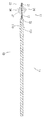
- FIG. 1 is an external view showing an external configuration of a cell collection device 10.
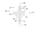
- FIG. 3 is a cross-sectional view along the first end second end direction showing the external configuration of the cell collection device 10.
- FIG. 2 is a front view of a first end side of the cell collection device 10.
- FIG. 3 is a cross-sectional view along the first end second end direction showing a state where the cap 50 is attached in the cell collection device 10.
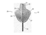
- 3 is an enlarged view of a cell collection member 12.
- the cell collection device 10 (an example of an intrauterine cell collection device) includes a rod-shaped member 11 and a cell collection member 12.
- the cell collection member 12 is fixed to the first end side of the rod-shaped member 11.
- the direction in which the elongated rod-shaped member 11 extends is referred to as the longitudinal direction 101.
- a virtual line passing through the center of the rod-shaped member 11 along the longitudinal direction 101 is referred to as a center line 102.
- a direction of rotation about the center line 102 is referred to as a rotation direction 103.
- the side which the operator of the rod-shaped member 11 has is called a 2nd end side (right side in FIG.1 and FIG.2), and the side to which the cell collection member 12 is fixed is a 1st end side (FIG. 1). And the left side in FIG.
- the rod-shaped member 11 is a circular member that is elongated in the longitudinal direction 101.
- the rod-shaped member 11 may be either solid or hollow.
- the material and shape of the rod-shaped member 11 are not particularly limited, and for example, the outer shape may be a polygonal shape.
- the external dimensions of the rod-shaped member 11 and the length in the longitudinal direction 101 are optimally set so that the operator has the second end side and allows the cell collection member 12 to reach the cervix 40.
- the cell collection member 12 has a thread-like band 20, a shaft portion 21, and a hub 22.
- the cell collection member 12 may be fixed, for example, by inserting the shaft portion 21 into a hole formed on the first end side of the hub 22 with an adhesive or the like, or the shaft portion 21 and the hub 22 are integrally molded. Alternatively, it may be fixed by heat welding, or another manufacturing method may be adopted.
- the shaft portion 21 has a thread-like band 20 made of synthetic resin fixed to a shaft member 11 made of stainless steel or the like.
- the thread-like band 20 is formed from a plurality of thread-like bodies 25.
- the shaft portion 21 extends along the center line 102 of the rod-like member 11, and the thread-like belt 20 may be fixed so as to expand radially from the outer surface of the shaft portion 21.
- 20 and the shaft portion 21 may be integrally molded, or other shapes may be employed.
- the hub 22 is provided, but it is not particularly necessary to provide it.
- the shaft portion 21 is preferably made of a metal material such as stainless steel or iron, but may be made of a resin material such as polypropylene or polyethylene.
- the shaft portion 21 is formed by twisting two metal wires made of stainless steel, but other shapes may be adopted.
- the cell collection member 12 sandwiches the central portion of the thread-like body 25 between two metal wires, and forms the thread band 20 radially on the outer surface of the shaft portion 21.
- the cell collection member 12 can further prevent the filamentary band 20 from falling off by sandwiching and fixing the filament 25.
- the thread-like band 20 may be bonded to the resin shaft portion 21 using an adhesive or the like, or another fixing method may be adopted.
- the thread band 20 refers to a plurality of thread bodies 25.
- the thread-like body 25 is 1 to 20 thread-like objects, and is fixed to the shaft portion 21.
- the end portion of the filament 25 fixed to the shaft portion 21 is referred to as a fixed end
- the unfixed end portion is referred to as a free end.
- the base end portion of the filament 25 when the base end portion of the filament 25 is fixed to the shaft portion 21, the base end portion becomes a fixed end, the tip end portion becomes a free end, and one free end is provided.
- the center part of the filament 25 is fixed to the shaft part 21, the center part becomes a fixed end and two free ends are provided.
- the number of the fixed ends is not necessarily one, and the fibrous thread-like body 25 may be fixed to the shaft portion 21 at two points to form two fixed ends.
- the free end and the fixed end of the filament 25 need not be one each, and may be plural.
- the thread-like band 20 is radially fixed to the outer surface of the shaft portion 21.
- the thread-like band 20 may be fixed continuously in the rotation direction 103, or may be fixed spirally continuously on the outer surface of the shaft portion 21 from the first end to the second end.
- the thread-like band 20 is fixed so as to sandwich two metal wires in a twisted manner, and is fixed to the outer surface in a spiral shape.
- the thread-like band 20 should just be radially fixed as the whole outer surface, and another shape may be employ
- Such a thread-like band 20 is made of a flexible fiber such as a synthetic resin.
- a synthetic resin a polyamide resin or the like is preferably used. Further, wool or the like can be adopted as the thread-like band 20.
- the thread-like band 20 may be formed integrally with the resin-molded shaft portion 21. In that case, the boundary between the shaft portion 21 and the thread-like band 20 is referred to as a fixed end.
- chemical treatment or the like may be performed on the surface of the filamentous band 20 so as to be suitable for cell collection. Note that it is not always necessary to chemically treat the entire surface of the thread-like band 20, and only the surface near the free end may be chemically treated.
- as a material of the filamentous band 20 what is melt
- the thread band 20 includes a first thread-like part 23 fixed to the first end side of the shaft part 21 and a second thread-like part fixed to the second end side of the shaft part 21. 24.
- the first filament 23 is provided for collecting cells existing around the cervical canal 41 of the cervix 40.
- the first thread-like portion 23 is fixed to the shaft portion 21 so that the free end faces the outer peripheral direction.
- the outer peripheral direction here refers to a direction substantially perpendicular to the center line 102.
- the first thread-like portion 23 is fixed so that the free end is oriented in a substantially vertical direction with respect to the center line 102.
- any angle may be adopted as the substantially vertical direction. Therefore, that the free end of the first thread-like portion 23 faces in the outer peripheral direction means that the angle between the direction in which each thread-like band 20 of the first thread-like portion 23 extends and the center line 102 is between 80 ° and 100 °. In other words.
- the second filamentous part 24 is for collecting cells present in the outer uterine ostium 42 around the entrance of the cervix 40.
- the second thread-like portion 24 is provided such that the free end is positioned closer to the first end than the fixed end, and the free end faces the first end. That is, the position along the longitudinal direction 101 of the fixed end in one thread-like body 25 in which the free end continues from the fixed end among the respective thread-like bands 20 constituting the second thread-like portion 24 is the longitudinal direction 101 of the free end. It is on the first end side from the position along.
- one thread-like body 25 in which the free end is continuous from the fixed end among the respective thread-like bands 20 constituting the thread-like portion 24 is connected to the center line 102 from the fixed end fixed to the shaft portion 21 toward the free end. After extending in the intersecting direction, it is gradually curved along the center line 102 toward the first end side, and the vicinity of the free end of the filament 25 extends toward the first end side. As a result, as shown in FIG. 3, most of the free end of the second filamentous portion 24 can come into contact with the external uterine ostium 42 during cell collection. That is, the contact surface 26 is formed by the free end of the second thread-like portion 24 that is in contact with the outer uterine ostium 42.
- the cells existing in the outer uterine ostium 42 can be collected safely and efficiently by the contact surface 26 formed by the free end.
- the contact surface 26 is curved and fixed to the shaft portion 21 at a substantially constant interval so that the free end is directed to the first direction from the fixed end.
- the free ends of the respective filamentous bodies 25 constituting the are positioned on the virtual plane.
- the contact surface 26 that is a virtual surface can adopt various shapes such as a combination of a plane, a curved surface, and a plurality of surfaces according to the shape of the outer uterine ostium 42 such as a rough surface, a flat surface, or a curved surface.
- the curved shape of each filament 25 in the second filament 24 is formed by attaching a ridge so that the free end of the second filament 24 faces the first end by heat, pressure, electrostatic action, or chemical treatment. It may be held.
- the second thread-like part 24 has an outer thread-like band 27 fixed to the second end side of the second thread-like part 24 most.
- the outer thread-like belt 27 has the longest length along the thread-like body 25 from the fixed end to the free end in each thread-like body 25 constituting the second thread-like portion 24.
- the outer thread-like band 27 forms a substantially tulip shape when each thread-like body 25 extending from the shaft portion 21 exists 360 ° in the rotation direction around the shaft portion 21.
- the angle formed by the tangent line 28 (including the free end) of each thread 25 and the shaft portion 21 (center line 102) in the vicinity of the free end of each thread 25 in the outer thread 27 is 15 ° to 45 °. ° is preferred, but any angle may be employed.
- a safety region 13 where the thread-like band 20 is not fixed can be provided in the gap between the cell collecting member 12 and the rod-like member 11 in the shaft portion 21.
- the safety region 13 is formed by an exposed shaft portion 21 to which the thread band 20 is not fixed.
- the shaft portion 21 of the safety area 13 may be covered with a cover member or the like.
- the cap 50 has a cylindrical shape capable of containing the cell collection member 12, and ends 51 and 52 serving as both ends thereof are open. Therefore, the inner diameter of the cap 50 is equal to or slightly larger than the maximum outer diameter of the first thread-like portion 23.
- the first end side of the cap 50 that is, the end 51 that does not serve as the insertion port for the cell collection member 12 may be closed, and the inner diameter of the cap 50 is not necessarily constant along the longitudinal direction 101. It does not have to be.
- a groove, a rib, or the like may be provided on the inner peripheral surface of the cap 50 in order to improve the detachability or to keep the shape of the cell collection member 12.
- the cap 50 is formed of a transparent synthetic resin material, but may be formed of other colored materials.
- the cell collection device 10 may use the rod-shaped member 11 and the cell collection member 12 separately after collecting intrauterine cells.
- a thin breaking point may be provided between the two members.
- the lock mechanism 110 described in PCT / JP2014 / 063706 in which the hub 22 is provided at the second end of the cell collection member 12 and the operation member 111 is provided at the first end of the rod-like member 11 is employed. .
- FIG. 4 An example of a uterine cell collection method using the intrauterine cell collection device 10 of the present embodiment will be described.
- the patient's vagina is kept open with a colposcope (not shown).
- the intrauterine cell collection device 10 is stored with the cell collection member 12 covered with a cap 50.
- the cap 50 is moved to the first end side relative to the cell collection member 12, and the cap 50 is removed.
- a part of the second thread-like portion 24 is in contact with the cap 50.
- the free end of the second thread-shaped portion 24 faces the first end side, and the substantially tulip-shaped second thread-shaped portion 24 has a smaller outer diameter from the second end side of the shaft portion 21 toward the first end side. This is a tapered shape.
- the cap 50 can hold the second thread-like portion 24 in a collecting state in which each free end faces the first end side and is closer to the shaft portion 21 than the natural state.
- the natural state of the second filamentous portion is a substantially tulip shape shown in FIG.
- the collection-like body is such that the vicinity of the free end of the outer thread-like band 27 of the second thread-like portion 24 is in contact with the inner peripheral surface of the cap 50, and the free end of the outer thread-like band 27 and the shaft
- the shortest distance with the part 21 is a state band which is shorter than the shortest distance between the free end of the outer thread-like band 27 and the shaft part 21 in the natural state.
- the cap 50 that is moved relative to the cell collection member 12 toward the first end side is: It can be easily removed without resistance of the thread-like band 20.
- the second filamentous portion 24 is covered with the cap 50 with the free end facing the first end before use, the cell collection member 12 is covered with the cap 50 and the intrauterine cell Even if the collection device 10 is stored for a long period of time, the shape change of the filamentous band 20 can be suppressed.
- the second filament 24 with the free end of the filament 20 facing the first end in the natural state when the cell collection member 12 is again covered with the cap 50 after the intrauterine cell collection device 10 is used, the second filament 24 with the free end of the filament 20 facing the first end in the natural state.
- the cap 50 is inserted so as to move relative to the cell collection member 12 toward the second end side against the flow of the filamentous band 20 in FIG. As a result, the free end of the second thread-like portion 24 facing the first end side is secondly moved by the cap 50 that moves relative to the cell collection member 12 while abutting the vicinity of the opening of the cap 50 and the inner peripheral surface.
- the cap 50 is covered in a state of being deformed so as to face the end side. Since the direction in which the free end of the second filamentous portion 24 of the intrauterine cell device 10 covered by the cap 50 faces before and after use is different, the appearance before and after use of the intrauterine cell collection device 10 is clearly defined by appearance. It can also be distinguished.
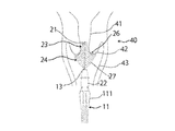
- the intrauterine cell collection device 10 passes through the opening of the colposcope, the first filament 23 is located in the cervix 41, and the second filament 24 is the external uterine ostium 42. Is inserted into the vagina up to the position where it touches.
- the uterine cell collection device 10 is rotated in the rotation direction 103 or alternately moved toward the first end side and the second end side along the longitudinal direction 101, whereby the cell collection unit 12 is moved to the cervical canal 41. Then, the cells are rubbed against the outer uterine ostium 42, whereby cells in the uterus are collected in the cell collection unit 12.
- the intrauterine cell collection device 10 has a first filament 23 that collects cells of the cervical canal 41 and a second filament 24 that collects cells of the external uterine ostium 42. Therefore, since the uterine cell collection device 10 collects a wide range of cells of the cervical canal 41 and the external uterine ostium 42 by a single insertion, it can efficiently collect SC-junction cells that have different positions depending on age and constitution. Can do.
- the intrauterine cell collection device 10 collects intrauterine cells by contacting the contact surface 26 where the free ends meet with the outer uterine ostium 42.
- the filamentous band and the cells are more separated than when the cells are collected with the entire length of the filamentous band constituting the second filamentous part 25. Since the contact area is small, the filamentous band efficiently scrapes the cells, and the cells of the outer uterine ostium 42 are collected.
- the contact surface 26 is also formed including an outer thread-like band 27 which is a thread-like band having the longest outer periphery. That is, the contact surface 26 is configured as a set of free ends of each thread-like band 20 from the center to the outer periphery. Therefore, even the free end of the outer thread-like band 27 fixed to the most second end side of the shaft portion 21 can be brought into contact with the outer uterine ostium 42. Thus, each filamentous band 20 fixed to the shaft portion 21 of the cell collection device 10 can be effectively used without waste as a location for collecting cells.
- the angle formed by the tangent line 28 including the free end of the outer thread-like band 27 of the intrauterine cell collection device 10 and the shaft portion 21 is 30 °.
- the angle formed by the tangent line 28 and the shaft portion 21 is smaller than 15 °, the contact surface 26 becomes small, and only cells near the entrance of the external uterine ostium 42 can be collected from the cervical canal 41 where the SC-junction exists. Therefore, the angle formed by the tangent line 28 and the shaft portion 21 of the intrauterine cell collection device 10 is preferably 15 ° or more.
- the angle formed by the tangent line 28 and the shaft portion 21 is large, the contact surface 26 becomes large, and the possibility that the thread-like band 20 comes into contact with various places increases, and other cells that are not related to the occurrence of cervical cancer can be removed. There is a risk that it will also be collected. Therefore, the angle is preferably 45 ° or less, but other angles may be adopted depending on the material of the cell collection member 12 or the like.
- a safety region 13 is provided at the second end of the cell collection member 12.
- the intrauterine cell collection device 10 may be inserted too far into the neck 40 and the rod 11 may contact the outer uterine ostium 42 and damage the uterine ostium 42.
- the safety region 13 is provided at the second base end portion of the cell collection member 12, it is possible to suppress damage to the uterine ostium 42 even when the intrauterine cell collection device 10 is inserted into the back of the neck 40.
- the intrauterine cell collection device 10 After collecting cells from the cervix 40, the intrauterine cell collection device 10 is extracted from the vagina. The collected cells 12 of the extracted intrauterine cell collection device 10 are smeared on a slide glass and the collected cells are observed with a microscope. Alternatively, when an inspection is performed at the inspection center, the cell collection member may be separated from the rod-shaped member, and only the cell collection member is placed in a container and transported to the inspection center for use.
- a hub 22 is provided at the second end of the cell collection member 12, and a lock mechanism 110 is provided with an operation member 111 provided at the first end of the rod-like member 11. After cell collection, the operation member 111 is pressed toward the center line 102 to release the engagement between the hub 22 and the operation member 111. The engagement of the lock mechanism 110 is released, and the cell collection member 12 can be easily separated from the rod-shaped member 11.
- the intrauterine cell apparatus 10 has the configuration as in the present embodiment, a sufficient amount of cells in the cervical canal 41 and the external uterine ostium 42 in which SC-junction exists without a plurality of insertions are required. Since it can be collected, it is possible to collect cells safely and efficiently for the practitioner and the patient.
Landscapes
- Health & Medical Sciences (AREA)
- Life Sciences & Earth Sciences (AREA)
- Surgery (AREA)
- Animal Behavior & Ethology (AREA)
- Biomedical Technology (AREA)
- Heart & Thoracic Surgery (AREA)
- Medical Informatics (AREA)
- Molecular Biology (AREA)
- Pathology (AREA)
- Engineering & Computer Science (AREA)
- General Health & Medical Sciences (AREA)
- Public Health (AREA)
- Veterinary Medicine (AREA)
- Gynecology & Obstetrics (AREA)
- Reproductive Health (AREA)
- Surgical Instruments (AREA)
Abstract
【課題】子宮頸管及び外子宮口部の細胞を安全に効率的に採取できる子宮内細胞採取装置を提供することにある。 【解決手段】第1端及び第2端を有する棒状部材11と、棒状部材11の第1端側に設けられた細胞採取部材12とを有し、前記細胞採取部材12は、軸部21と、糸状帯20とを含み、前記糸状帯20の固定端は、前記軸部21の外面に放射状に固定さており、前記軸部21の第1端側に固定された糸状帯20の自由端が外周方向に向くように位置された第1糸状部23と、前記軸部21の第1端側より第2端側に固定された糸状帯20は、自由端が固定端より第1端方向に位置された第2糸状部24であり、前記第2糸状部24は、自由端が第1端方向に向くように位置される。
Description
本発明は、子宮頸癌検診のために子宮頸管及び外子宮口部の細胞を採取する子宮内細胞採取装置に関する。
子宮頸癌の診断において、子宮頸部から細胞を採取して、採取した細胞をスライドガラスに塗抹して顕微鏡で観察する手法が行われている。このような診断は、子宮頸部細胞診と称されている。採取した細胞を検査センターなどに搬送して、検査センターにて観察することも行われている。
子宮頸部からの細胞の採取には、棒状の部材の先端にブラシ等が設けられたデバイスが用いられる。デバイスのブラシ等が子宮頸部と接触している状態で、棒状の部材を回転させることにより、ブラシ等に子宮頸部の細胞が付着し採取される。そして、細胞が付着しているブラシ等をスライドガラスに擦りつけて塗りつけて細胞が塗抹される。また、検査センターにて検査が行われる場合には、棒状の部材を破断することなどによって、デバイスのブラシ部分のみが容器に入れられて検査センターへ搬送されることもある。
子宮頸癌は、子宮頸管と外子宮口部の間に存在する扁平上皮と円柱上皮細胞の境目であるSC-ジャンクションに多く見られる癌である。SC-ジャンクションは、年齢や体質によって位置が異なっている。正確な検診結果を得るために、子宮頸部癌検診では、子宮頸管および外子宮口部の細胞を採取する必要がある。
特許文献1に記載された細胞採取装置は、子宮頸管及び外子宮口部の細胞を採取できるよう子宮頸管部の細胞を採取する短毛部と、外子宮口部の細胞を採取する長毛部を有している。短毛部の先端で子宮頸管の細胞を採取し、長毛部の腹部で子宮口部の細胞を採取する。
特許文献1に記載された細胞採取装置は、外子宮口部に接触しない長毛部が存在するため、細胞採取装置に設けられた毛部を充分に活用することが出来なかった。また、特許文献1に記載された細胞採取装置は、外子宮口部の細胞が長毛部の腹部で採取される特許文献1における図4のような場合、短毛部の先端で採取される子宮頸管の細胞の数にに比べ、長毛部の腹部で採取される外子宮口部の細胞は十分な数を採取できない。本発明は、上述の問題に鑑みてなされたものであって、その解決課題は、子宮頸管及び外子宮口部の細胞を安全に効率的に採取できる子宮内細胞採取装置を提供することにある。
以下、このような課題を解決するためになされた本発明の態様を記載する。なお、以下に記載の各態様において採用される構成要素は、可能な限り任意の組み合わせで採用可能である。
子宮内細胞採取装置は、第1端及び第2端を有する棒状部材と、棒状部材の第1端側に設けられた細胞採取部材とを具備する。前記細胞採取部材は、軸部と、糸状帯と、を有している。前記糸状帯は、各固定端が前記軸部にそれぞれ固定されて各固定端が放射状に配置された第1糸状部及び第2糸状部を有している。前記第1糸状部は、前記軸部の第1端側に固定されており、各自由端が外周方向に向いている。前記第2糸状部は、前記第1糸状部より前記軸部の第2端側に固定されており、各自由端が各固定端より第1端側に位置しており、且つ各自由端が第1端側へ向いている。
好ましくは、前記第2糸状部の各自由端は、前記軸部の第1端側を向く接触面を形成する。
好ましくは、前記第2糸状部は、当該第2糸状部において前記軸部の最も第2端側に固定された外側糸状帯を有しており、前記外側糸状帯は、当該第2糸状部において固定端から自由端までの長さが最も長いものある。
好ましくは、前記第2糸状部は、前記軸部の第2端側へ向かうにつれて、各糸状帯の固定端から自由端までの長さが徐々に長くなるものである。
好ましくは、前記軸部は、前記第2糸状部より第2端側に、前記糸状帯が固定されていない安全領域を有する。
好ましくは、前記細胞採取部材を覆う円筒形状のキャップを更に具備しており、前記キャップは、前記第2糸状部を、各自由端が第1端側を向いており、且つ自然状態より前記軸部に近づいた収集状態に保持可能なものである。
子宮内細胞採取装置の一態様は、第1端及び第2端を有する棒状部材と、棒状部材の第1端側に設けられた細胞採取部材とを有し、前記細胞採取部材は、軸部と、糸状帯とを含み、前記糸状帯の固定端は、前記軸部の外面に放射状に固定さており、前記軸部の第1端側に固定された糸状帯の自由端が外周方向に向くように位置された第1糸状部と、前記軸部の第1端側より第2端側に固定された糸状帯は、自由端が固定端より第1端方向に位置された第2糸状部であり、前記第2糸状部は、最も第2端側に固定された外側糸状帯を有し、前記第2糸状部は、自由端が第1端方向に向くように位置されたことを特徴とするものである。
子宮内細胞採取装置の一態様は、前記第2糸状部が、自由端により接触面を形成することを特徴とするものである。
子宮内細胞採取装置の一態様は、外側糸状帯は、最も長い糸状帯であることを特徴とするものである。
子宮内細胞採取装置の一態様は、前記細胞採取部材と前記棒状部材の間隙に、前記糸状帯が固定されていない安全領域を有することを特徴とするものである。
本発明に従う構造とされた子宮内細胞採取装置によれば、子宮頸管及び外子宮口部の細胞を安全に効率的に採取できる。
以下、本発明の実施形態について、図面を参照しつつ説明する。なお、本実施例は、本発明の一例にすぎず、本発明の要旨が変更されない範囲において、本発明の実施形態が適宜変更されてもよいことは言うまでもない。
図1及び図2に示されるように、細胞採取装置10(子宮内細胞採取装置の一例)は、棒状部材11及び細胞採取部材12を有する。細胞採取部材12は、棒状部材11の第1端側に固定されている。本実施例において、細長な棒状部材11が延びる方向が長手方向101と称される。長手方向101に沿って棒状部材11の中心を通る仮想線が中心線102と称される。中心線102を中心として回転する方向が回転方向103と称される。また、本明細書において、棒状部材11の施術者が持つ側が第2端側(図1及び図2における右側)と称され、細胞採取部材12が固定されている側が第1端側(図1及び図2における左側)と称される。
棒状部材11は、長手方向101に細長な円形状の部材である。棒状部材11は、中実でも中空のどちらでもよい。棒状部材11の素材や形状は特に限定されるものではなく、例えば、外形が多角形状であってもよい。棒状部材11の外形寸法や長手方向101の長さは、第2端側を施術者が持って、細胞採取部材12を子宮頸部40へ到達させるに最適に設定される。
図1及び図2に示されるように、細胞採取部材12は、糸状帯20、軸部21、ハブ22を有する。細胞採取部材12は、例えばハブ22の第1端側に形成された孔に軸部21を挿入し、接着剤などにより固定してもよいし、軸部21とハブ22が一体に成型してもよいし、熱溶着で固定してもよいし、他の製造方法が採用されてもよい。軸部21は、ステンレス製などの軸部材11に合成樹脂製の糸状帯20が固定される。糸状帯20は、複数の糸状体25から形成される。本実施例のように、棒状部材11の中心線102に沿って軸部21が延びており、その軸部21の外面から放射状に拡がるように糸状帯20が固定されてもよいし、糸状帯20と軸部21が一体に成型してもよいし、他の形状が採用されてもよい。また、本実施例では、ハブ22を有しているが特に設けなくてもよい。
軸部21は、好適にはステンレス、鉄等の金属材料が採用されるが、ポリプロピレン、ポリエチレン等の樹脂材料が採用されてもよい。本実施例では、ステンレスからなる二本の金属線を撚り合わせて形成された軸部21であるが他の形状が採用されてもよい。細胞採取部材12は、軸部21の撚り工程の際において、二本の金属線の間に糸状体25の中心部を挟み込み、軸部21の外面に放射状に糸状帯20を形成している。細胞採取部材12は、糸状体25を挟み込んで固定することにより、糸状帯20の脱落をより一層防止できる。また、接着剤などを用いないため、接着剤の溶出などによる患者や検体への影響を考慮する必要がない。なお、糸状帯20の固定方法は、樹脂製の軸部21に接着材などを用いて糸状帯20を接着してもよいし、他の固定方法が採用されてもよい。
糸状帯20は、複数の糸状体25のことを称する。糸状体25は、1~20本の糸状物であり、軸部21にそれぞれ固定されている。本明細書では、軸部21に固定されている糸状体25の端部を固定端と称し、固定されていない端部を自由端と称する。例えば糸状体25の基端部を軸部21に固定した場合は、基端部が固定端となり、先端部が自由端となり、自由端を一つ備えることとなる。また、糸状体25の中心部を軸部21に固定した場合は、中心部が固定端となり、自由端を二つ備えることとなる。また、固定端が一つである必要はなく、繊維状の糸状体25を軸部21に二点で固定し、二つの固定端としてもよい。このように糸状体25の自由端及び固定端は、それぞれ一つである必要はなく複数であってもよい。
図3に示されるように、糸状帯20は、軸部21の外面に放射状に固定されている。放射状とは、回転方向103に連続して糸状帯20が固定されてもよいし、軸部21の外面に第1端から第2端にかけて連続して螺旋状に固定されてもよい。本実施例では、二本の金属線を撚り合わせに挟み込むように糸状帯20が固定されており、螺線状に外面に固定されている。なお、外面全体として糸状帯20が放射状に固定されておればよく、他の形状が採用されてもよい。
かかる糸状帯20は、合成樹脂などの柔軟性のある繊維などが採用される。合成樹脂としては、ポリアミド樹脂などが好適に採用される。また、糸状帯20として羊毛などを採用することもできる。他にも樹脂成形された軸部21と一体的に糸状帯20を成形させてもよい。その場合、軸部21と糸状帯20の境目を固定端と称する。また、細胞の採取に適するよう糸状帯20の表面に化学処理などが行われてもよい。なお、必ずしも糸状帯20の全表面を化学処理する必要はなく、自由端付近の表面のみが化学処理されてもよい。また、糸状帯20の材料としては、細胞回収液に溶解するものが採用されてもよい。
図5及び図6に示されるように糸状帯20は、軸部21の第1端側に固定された第1糸状部23と、軸部21の第2端側に固定された第2糸状部24とを含んでいる。第1糸状部23は、子宮頸部40の子宮頸管41周辺に存在する細胞を採取するために設けられている。第1糸状部23は、管状の子宮頸管41の細胞を効率的に採取するために自由端が外周方向に向くように位置するよう軸部21に固定されている。ここでいう外周方向とは、中心線102に対して略垂直方向を指す。つまり本実施例では、第1糸状部23は、自由端が中心線102に対して略垂直方向に向くように固定されている。なお、略垂直方向とは、中心線102と固定された糸状体25の角度が80°乃至100°の間であれば、どのような角度が採用されてもよい。したがって、第1糸状部23の自由端が外周方向へ向くとは、第1糸状部23の各糸状帯20が延びる方向が、中心線102となす角度が80°乃至100°の間であるとも換言できる。
第2糸状部24は、子宮頸部40の入口周辺の外子宮口部42に存在する細胞を採取するためのものである。第2糸状部24は、自由端が、固定端よりも第1端側に位置し、自由端が第1端側を向くように設けられている。すなわち、第2糸状部24を構成する各糸状帯20のうち固定端から自由端が連続する1本の糸状体25における固定端の長手方向101に沿った位置が、自由端の長手方向101に沿った位置より第1端側にある。また、糸状部24を構成する各糸状帯20のうち固定端から自由端が連続する1本の糸状体25は、軸部21に固定された固定端から自由端へ向かって、中心線102と交差する方向へ延びた後、第1端側へ向かって中心線102に沿うように次第に湾曲しており、糸状体25の自由端付近が第1端側へ向かって延びている。その結果、図3に示されるように、細胞採取時に第2糸状部24の自由端の大部分が、外子宮口部42に当接できる。つまり外子宮口部42に当接される第2糸状部24の自由端によって接触面26が形成される。本実施例は、自由端により形成される接触面26によって外子宮口部42に存在する細胞を安全にまた効率的に採取することができる。接触面26は、軸部21に略一定の間隔で、自由端が固定端より第1方向に向くように位置されるために湾曲して糸状体25が固定された結果、第2糸状部24を構成する各糸状体25の自由端が仮想面に位置している。仮想面である接触面26は、粗面状や平面状、曲面状など外子宮口部42の形状に合わせて、平面や曲面、複数の面の組み合わせなどの様々な形状を採用することができる。また第2糸状部24における各糸状体25の湾曲形状は、熱や圧力、静電的作用、化学処理によって、第2糸状部24の自由端が第1端側を向くよう癖を付けることによって保持されてもよい。
第2糸状部24は、第2糸状部24の最も第2端側に固定された外側糸状帯27を有する。外側糸状帯27は、第2糸状部24を構成する各糸状体25において固定端から自由端までの糸状体25に沿った長さが最も長いものである。外側糸状帯27は、軸部21から延びる各糸状体25が軸部21を中心として回転方向に360°存在することによって略チューリップ形状を形成する。外側糸状帯27における各糸状体25の自由端付近における各糸状体25の接線28(自由端を含んでいる。)と軸部21(中心線102)とが形成する角度は、15°乃至45°が好ましいが、どのような角度が採用されてもよい。
軸部21における細胞採取部材12と棒状部材11の間隙に糸状帯20が固定されていない安全領域13を設けることができる。安全領域13は、糸状帯20が固定されていない露出した軸部21によって形成される。安全領域13の軸部21をカバー部材などで覆ってもよい。
図4に示すようにキャップ50は、細胞採取部材12を内包可能な円筒形状であり、その両端となる端51,52は開口している。したがって、キャップ50の内径は第1糸状部23の最大外径と同等ないし若干大きい。なお、キャップ50の第1端側、すなわち細胞採取部材12の挿入口とならない側の端51は塞がれていてもよいし、また、キャップ50の内径は必ずしも長手方向101に沿って一定でなくてもよい。また、キャップ50の内周面に取り外し性をよくするためや細胞採取部材12の形状を保つために溝やリブなどを設けてもよい。本実施例では、キャップ50は、透明な合成樹脂材料によって形成されているが、他の有色材料によって形成してもよい。
細胞採取装置10は、子宮内細胞を採取後に棒状部材11と細胞採取部材12を分離して使用することもある。棒状部材11と細胞採取部材12を分離するため、両部材間に薄肉の破断点を設けてもよい。また、解除操作により分離するロック機構を設けてもよい。本実施例では、細胞採取部材12の第2端部にハブ22と、棒状部材11の第1端部に操作部材111を設けたPCT/JP2014/063706に記載のロック機構110を採用している。
本実施例の子宮内細胞採取装置10を用いた子宮細胞採取方法の一例について説明する。患者の膣を膣鏡(図示せず)で開いた状態に維持する。図4に示されるように、子宮内細胞採取装置10は、キャップ50によって細胞採取部材12が覆われた状態で保存されている。使用に際して、キャップ50を細胞採取部材12に対して相対的に第1端側へ移動させキャップ50を取り外す。キャップ50には、第2糸状部24の一部が当接している。第2糸状部24の自由端は、第1端側へ向いており、略チューリップ形状の第2糸状部24は、軸部21の第2端側から第1端側へ向けて外径が小さくなるテーパ形状である。キャップ50は、第2糸状部24を、各自由端が第1端側を向いており、且つ自然状態より軸部21に近づいた収集状態に保持可能なである。第2糸状部の自然状態とは、図1に示される略チューリップ形状である。収集状体とは、図4に示されるように、第2糸状部24の外側糸状帯27の自由端付近がキャップ50の内周面に当接しており、外側糸状帯27の自由端と軸部21との最短距離が、自然状態におけるが外側糸状帯27の自由端と軸部21との最短距離よりも短くなった状帯をいう。収集状態において、第2糸状部24の各糸状帯20の自由端は第1端側を向いているので、細胞採取部材12に対して第1端側へ相対的に移動されるキャップ50は、糸状帯20の抵抗なく容易に取り外すことができる。また、使用前まで第2糸状部24は、自由端が第1端側を向いた状態でキャップ50に覆われているため、細胞採取部材12がキャップ50によって覆われた状態で、子宮内細胞採取装置10が長期間保存されても、糸状帯20の形状変化を抑えることができる。また、子宮内細胞採取装置10が使用された後、再度キャップ50により細胞採取部材12が覆われた場合、自然状態において糸状帯20の自由端が第1端側を向いた第2糸状部24における糸状帯20の流れに逆らって、キャップ50が細胞採取部材12に対して相対的に第2端側へ移動するように挿入される。その結果、第1端側へ向いている第2糸状部24の自由端は、キャップ50の開口付近や内周面に当接しつつ、細胞採取部材12に対して相対移動するキャップ50によって第2端側へ向くように変形された状態でキャップ50に覆われる。キャップ50に覆われた使用前と使用後の子宮内細胞装置10の第2糸状部24の自由端が向く方向が異なるため、子宮内細胞採取装置10の使用前と使用後を外観により明確に区別することもできる。
図7に示されるように、子宮内細胞採取装置10は、膣鏡の開口部を通過し、第1糸状部23が子宮頸管41内に位置し、第2糸状部24が外子宮口部42に当接する位置まで膣内に挿入される。子宮細胞採取装置10は、回転方向103へ回転されたり、または、長手方向101に沿って第1端側及び第2端側へ交互に動かされたりすることによって、細胞採取部12が子宮頸管41及び外子宮口部42に擦りつけられ、これにより子宮内の細胞が細胞採取部12に採取される。子宮内細胞採取装置10は、子宮頸管41の細胞を採取する第1糸状部23と、外子宮口部42の細胞を採取する第2糸状部24を有する。その為、子宮細胞採取装置10は、一度の挿入で子宮頸管41及び外子宮口部42の細胞を幅広く採取するため、年齢や体質によって位置の異なるSC-ジャンクションの細胞を効率的に採取することができる。
子宮内細胞採取装置10は、外子宮口部42に自由端が集合する接触面26が当接されることにより、子宮内細胞を採取する。第2糸状部24の自由端により外子宮口部42の細胞が採取されると、例えば第2糸状部25を構成する糸状帯の全長で細胞を採取する場合よりも、糸状帯と細胞とが接触する面積が小さくなるため、糸状帯が効率的に細胞を掻き集めて外子宮口部42の細胞が採取される。
接触面26は、外周が最も長い糸状帯である外側糸状帯27も含んで形成されている。つまり、接触面26は、中心から外周まで各糸状帯20の自由端の集合として構成されている。したがって、軸部21の最も第2端側に固定された外側糸状帯27の自由端までも外子宮口部42に当接することが可能となる。このように細胞採取装置10の軸部21に固定された各糸状帯20を、細胞を採取する箇所として無駄なく有効に使用することができる。
本実施例では、子宮内細胞採取装置10の外側糸状帯27の自由端を含む接線28と軸部21(中心線102)が形成する角度は、30°である。接線28と軸部21が形成する角度が15°よりも小さい場合、接触面26が小さくなり、SC-ジャンクションが存在する子宮頸管41から外子宮口部42の入り口付近の細胞しか採取することが出来ない恐れがあるその為、子宮内細胞採取装置10の接線28と軸部21が形成する角度は、15°以上が好ましい。また、接線28と軸部21が形成する角度が大きい場合、接触面26が大きくなり、糸状帯20が様々な箇所に接触する可能性が高まり子宮頸癌の発生に関係ない他の細胞などを併せて採取してしまう恐れがある。その為、好適には45°以下が好ましいが、細胞採取部材12の材料などによって、他の角度を採用してもよい。
本実施例では、細胞採取部材12の第2端部に安全領域13を設けている。子宮内細胞を採取する際に、子宮内細胞採取装置10を頸部40の奥に挿入しすぎてしまい棒状体11が外子宮口部42に接触し、子宮口部42を損傷してしまう恐れがある。細胞採取部材12の第2基端部に安全領域13を設けることにより、子宮内細胞採取装置10を頸部40の奥に挿入したとしても子宮口部42の損傷を抑えることが可能となる。
子宮頸部40から細胞を採取した後に、膣内から子宮内細胞採取装置10を抜き出す。抜き出された子宮内細胞採取装置10の採取部材12をスライドガラスに塗抹して採取した細胞を顕微鏡で観察する。あるいは、検査センターにて検査が行われる場合には、細胞採取部材を棒状部材から分離させ、細胞採取部材のみが容器に入れられて検査センターへ搬送されて使用されることもある。
本実施例では、細胞採取部材12の第2端部にハブ22を設け、棒状部材11の第1端部に操作部材111を設けたロック機構110を備えている。細胞採取後は、操作部材111を中心線102へ向かって押圧することにより、ハブ22と操作部材111との係合が解除される。ロック機構110の係合が解除され細胞採取部材12は棒状部材11から容易に分離することができる。
本実施例では、細胞採取部材12の第2端部にハブ22を設け、棒状部材11の第1端部に操作部材111を設けたロック機構110を備えている。細胞採取後は、操作部材111を中心線102へ向かって押圧することにより、ハブ22と操作部材111との係合が解除される。ロック機構110の係合が解除され細胞採取部材12は棒状部材11から容易に分離することができる。
子宮内細胞装置10は、本実施例のような構成を有することにより、複数回挿入する必要がなく一度の挿入でSC-ジャンクションが存在する子宮頸管41及び外子宮口部42の細胞を充分量採取することができるため、施術者および患者に対しても安全で効率的に細胞採取するが可能となる。
10:子宮内細胞採取装置、11:棒状部材、12:細胞採取部材、13:安産領域、20:糸状帯、21:軸部、22:ハブ、23:第1糸状部、24:第2糸状部、25:糸状体、26:接触面、27:外側糸状帯、28:接線、110:ロック機構、111:操作部材
Claims (10)
- 第1端及び第2端を有する棒状部材と、
棒状部材の第1端側に設けられた細胞採取部材とを具備するものであって、
前記細胞採取部材は、軸部と、糸状帯と、を有しており、
前記糸状帯は、各固定端が前記軸部にそれぞれ固定されて各固定端が放射状に配置された第1糸状部及び第2糸状部を有しており、
前記第1糸状部は、前記軸部の第1端側に固定されており、各自由端が外周方向に向いており、
前記第2糸状部は、前記第1糸状部より前記軸部の第2端側に固定されており、各自由端が各固定端より第1端側に位置しており、且つ各自由端が第1端側へ向いている子宮内細胞採取装置。 - 前記第2糸状部の各自由端は、前記軸部の第1端側を向く接触面を形成する請求項1に記載の子宮内細胞採取装置。
- 前記第2糸状部は、当該第2糸状部において前記軸部の最も第2端側に固定された外側糸状帯を有しており、
前記外側糸状帯は、当該第2糸状部において固定端から自由端までの長さが最も長いものある請求項1又は2に記載の子宮内細胞採取装置。 - 前記第2糸状部は、前記軸部の第2端側へ向かうにつれて、各糸状帯の固定端から自由端までの長さが徐々に長くなるものである請求項3に記載の子宮内細胞採取装置。
- 前記軸部は、前記第2糸状部より第2端側に、前記糸状帯が固定されていない安全領域を有する請求項1乃至4に記載の子宮内細胞採取装置。
- 前記細胞採取部材を覆う円筒形状のキャップを更に具備しており、
前記キャップは、前記第2糸状部を、各自由端が第1端側を向いており、且つ自然状態より前記軸部に近づいた収集状態に保持可能なものである請求項1乃至5に記載の子宮内細胞採取装置。 - 第1端及び第2端を有する棒状部材と、
棒状部材の第1端側に設けられた細胞採取部材とを有し、
前記細胞採取部材は、軸部と、糸状帯とを含み、
前記糸状帯の固定端は、前記軸部の外面に放射状に固定さており、
前記軸部の第1端側に固定された糸状帯の自由端が外周方向に向くように位置された第1糸状部と、
前記軸部の第1端側より第2端側に固定された糸状帯は、自由端が固定端より第1端方向に位置された第2糸状部であり、
前記第2糸状部は、最も第2端側に固定された外側糸状帯を有し、
前記第2糸状部は、自由端が第1端方向に向くように位置されたことを特徴とする子宮内細胞採取装置。 - 前記第2糸状部が、自由端により接触面を形成することを特徴とする請求項7に記載の子宮内細胞装置。
- 前記外側糸状帯は、最も長い糸状帯であることを特徴とする請求項8に記載の子宮内細胞装置。
- 前記細胞採取部材と前記棒状部材の間隙に、前記糸状帯が固定されていない安全領域を有することを特徴とする請求項7乃至9に記載の子宮内細胞装置。
Priority Applications (1)
| Application Number | Priority Date | Filing Date | Title |
|---|---|---|---|
| JP2016566561A JP6648699B2 (ja) | 2014-12-26 | 2015-12-25 | 子宮内細胞採取装置 |
Applications Claiming Priority (2)
| Application Number | Priority Date | Filing Date | Title |
|---|---|---|---|
| JP2014-264625 | 2014-12-26 | ||
| JP2014264625 | 2014-12-26 |
Publications (1)
| Publication Number | Publication Date |
|---|---|
| WO2016104779A1 true WO2016104779A1 (ja) | 2016-06-30 |
Family
ID=56150791
Family Applications (1)
| Application Number | Title | Priority Date | Filing Date |
|---|---|---|---|
| PCT/JP2015/086392 Ceased WO2016104779A1 (ja) | 2014-12-26 | 2015-12-25 | 子宮内細胞採取装置 |
Country Status (2)
| Country | Link |
|---|---|
| JP (1) | JP6648699B2 (ja) |
| WO (1) | WO2016104779A1 (ja) |
Cited By (2)
| Publication number | Priority date | Publication date | Assignee | Title |
|---|---|---|---|---|
| DE102018208769A1 (de) * | 2018-06-04 | 2019-12-05 | Bernhard Rinderknecht | Probeentnahmeanordnung für gynäkologische Untersuchungen |
| CN115886888A (zh) * | 2022-10-18 | 2023-04-04 | 合肥贝霓医药科技有限公司 | 一种男性生殖器脱落细胞采样装置 |
Citations (5)
| Publication number | Priority date | Publication date | Assignee | Title |
|---|---|---|---|---|
| WO1991016855A1 (en) * | 1990-05-10 | 1991-11-14 | Medscand Ab | Instrument for endo- and ectocervical sampling |
| JPH0531115A (ja) * | 1991-07-30 | 1993-02-09 | Onesuto Medical:Kk | 子宮細胞採取器 |
| JPH07501733A (ja) * | 1991-12-12 | 1995-02-23 | ボール・アソシエイツ・インコーポレーテッド | パパニコラウスミア採集装置 |
| US20020068881A1 (en) * | 2000-12-04 | 2002-06-06 | Kobren Myles S. | Cervical cytology instrument |
| JP2005528151A (ja) * | 2002-04-11 | 2005-09-22 | リチャーズ,ミカエル,オウェン | 細胞の採取装置および採取方法 |
Family Cites Families (5)
| Publication number | Priority date | Publication date | Assignee | Title |
|---|---|---|---|---|
| US5370128A (en) * | 1993-12-02 | 1994-12-06 | Wainwright; Sharon R. | Pap brush and pap unit container systems |
| AP9700944A0 (en) * | 1994-09-22 | 1997-04-30 | Bernard Chaffringeon | Single-use device for detecting or analyzing a body fluid. |
| FR2760626B1 (fr) * | 1997-03-11 | 1999-04-23 | Ccd Lab | Dispositif ameliore de prelevement uterin |
| US7413551B2 (en) * | 2005-09-27 | 2008-08-19 | David Decker | Combination self adjusting endocervical / exocervical sampling device and cell transport / preservation system |
| CN201085635Y (zh) * | 2007-07-17 | 2008-07-16 | 袁利 | 一次性使用的宫颈细胞采样刷 |
-
2015
- 2015-12-25 JP JP2016566561A patent/JP6648699B2/ja active Active
- 2015-12-25 WO PCT/JP2015/086392 patent/WO2016104779A1/ja not_active Ceased
Patent Citations (5)
| Publication number | Priority date | Publication date | Assignee | Title |
|---|---|---|---|---|
| WO1991016855A1 (en) * | 1990-05-10 | 1991-11-14 | Medscand Ab | Instrument for endo- and ectocervical sampling |
| JPH0531115A (ja) * | 1991-07-30 | 1993-02-09 | Onesuto Medical:Kk | 子宮細胞採取器 |
| JPH07501733A (ja) * | 1991-12-12 | 1995-02-23 | ボール・アソシエイツ・インコーポレーテッド | パパニコラウスミア採集装置 |
| US20020068881A1 (en) * | 2000-12-04 | 2002-06-06 | Kobren Myles S. | Cervical cytology instrument |
| JP2005528151A (ja) * | 2002-04-11 | 2005-09-22 | リチャーズ,ミカエル,オウェン | 細胞の採取装置および採取方法 |
Cited By (4)
| Publication number | Priority date | Publication date | Assignee | Title |
|---|---|---|---|---|
| DE102018208769A1 (de) * | 2018-06-04 | 2019-12-05 | Bernhard Rinderknecht | Probeentnahmeanordnung für gynäkologische Untersuchungen |
| WO2019234048A1 (de) | 2018-06-04 | 2019-12-12 | Bernhard Rinderknecht | Probeentnahmeanordnung für gynäkologische untersuchungen |
| US20210244390A1 (en) * | 2018-06-04 | 2021-08-12 | Mediscene Ag | Sample removal assembly for gynecological examinations |
| CN115886888A (zh) * | 2022-10-18 | 2023-04-04 | 合肥贝霓医药科技有限公司 | 一种男性生殖器脱落细胞采样装置 |
Also Published As
| Publication number | Publication date |
|---|---|
| JPWO2016104779A1 (ja) | 2017-10-05 |
| JP6648699B2 (ja) | 2020-02-14 |
Similar Documents
| Publication | Publication Date | Title |
|---|---|---|
| EP3738516B1 (en) | A device and a method for collecting and transferring samples of biological material | |
| KR102663428B1 (ko) | 검체 채취 스틱 | |
| US20170065261A1 (en) | Specimen collection device | |
| ES2640010T3 (es) | Aplicador para aplicar un producto cosmético sobre las pestañas o las cejas | |
| EP2719300B1 (en) | Epilator | |
| JPS639863B2 (ja) | ||
| JP2014083386A (ja) | 生体物質試料を採取及び移動させるための器具並びにその使用方法 | |
| WO2016104779A1 (ja) | 子宮内細胞採取装置 | |
| US20080313838A1 (en) | Scratcher | |
| KR200483788Y1 (ko) | 내시경 세척구 | |
| US11008631B2 (en) | Kit and method for collecting body fluid for medical diagnosis | |
| US20260013843A1 (en) | Sample collection stick | |
| US20230329680A1 (en) | Sample collection stick | |
| KR101501111B1 (ko) | 인조 속눈썹 | |
| TW202142187A (zh) | 一種拭子 | |
| US3358682A (en) | Tubular bandage applicator and cut-off | |
| RU157878U1 (ru) | Цитощетка "диатест" | |
| JP2011511680A (ja) | 治療器具 | |
| US10105019B2 (en) | Cleaning tool for body or facial piercings | |
| DE202012010698U1 (de) | Dreifinger-Glovebox-Handschuh | |
| US20210244390A1 (en) | Sample removal assembly for gynecological examinations | |
| WO2022190726A1 (ja) | 検体採取用スワブ | |
| CN106492339A (zh) | 一种美容卫生棉签 | |
| KR20150102572A (ko) | 내시경 세척구 | |
| CN218870330U (zh) | 一种采样拭子 |
Legal Events
| Date | Code | Title | Description |
|---|---|---|---|
| 121 | Ep: the epo has been informed by wipo that ep was designated in this application |
Ref document number: 15873347 Country of ref document: EP Kind code of ref document: A1 |
|
| ENP | Entry into the national phase |
Ref document number: 2016566561 Country of ref document: JP Kind code of ref document: A |
|
| NENP | Non-entry into the national phase |
Ref country code: DE |
|
| 122 | Ep: pct application non-entry in european phase |
Ref document number: 15873347 Country of ref document: EP Kind code of ref document: A1 |