WO2016104629A1 - アルミニウム製導電部材及びその製造方法 - Google Patents
アルミニウム製導電部材及びその製造方法 Download PDFInfo
- Publication number
- WO2016104629A1 WO2016104629A1 PCT/JP2015/086068 JP2015086068W WO2016104629A1 WO 2016104629 A1 WO2016104629 A1 WO 2016104629A1 JP 2015086068 W JP2015086068 W JP 2015086068W WO 2016104629 A1 WO2016104629 A1 WO 2016104629A1
- Authority
- WO
- WIPO (PCT)
- Prior art keywords
- aluminum
- conductive member
- film formation
- aluminum alloy
- phase particles
- Prior art date
- Legal status (The legal status is an assumption and is not a legal conclusion. Google has not performed a legal analysis and makes no representation as to the accuracy of the status listed.)
- Ceased
Links
Images

Classifications
-
- B—PERFORMING OPERATIONS; TRANSPORTING
- B22—CASTING; POWDER METALLURGY
- B22D—CASTING OF METALS; CASTING OF OTHER SUBSTANCES BY THE SAME PROCESSES OR DEVICES
- B22D11/00—Continuous casting of metals, i.e. casting in indefinite lengths
-
- B—PERFORMING OPERATIONS; TRANSPORTING
- B32—LAYERED PRODUCTS
- B32B—LAYERED PRODUCTS, i.e. PRODUCTS BUILT-UP OF STRATA OF FLAT OR NON-FLAT, e.g. CELLULAR OR HONEYCOMB, FORM
- B32B15/00—Layered products comprising a layer of metal
- B32B15/20—Layered products comprising a layer of metal comprising aluminium or copper
-
- C—CHEMISTRY; METALLURGY
- C22—METALLURGY; FERROUS OR NON-FERROUS ALLOYS; TREATMENT OF ALLOYS OR NON-FERROUS METALS
- C22C—ALLOYS
- C22C21/00—Alloys based on aluminium
-
- C—CHEMISTRY; METALLURGY
- C22—METALLURGY; FERROUS OR NON-FERROUS ALLOYS; TREATMENT OF ALLOYS OR NON-FERROUS METALS
- C22F—CHANGING THE PHYSICAL STRUCTURE OF NON-FERROUS METALS AND NON-FERROUS ALLOYS
- C22F1/00—Changing the physical structure of non-ferrous metals or alloys by heat treatment or by hot or cold working
- C22F1/04—Changing the physical structure of non-ferrous metals or alloys by heat treatment or by hot or cold working of aluminium or alloys based thereon
-
- C—CHEMISTRY; METALLURGY
- C23—COATING METALLIC MATERIAL; COATING MATERIAL WITH METALLIC MATERIAL; CHEMICAL SURFACE TREATMENT; DIFFUSION TREATMENT OF METALLIC MATERIAL; COATING BY VACUUM EVAPORATION, BY SPUTTERING, BY ION IMPLANTATION OR BY CHEMICAL VAPOUR DEPOSITION, IN GENERAL; INHIBITING CORROSION OF METALLIC MATERIAL OR INCRUSTATION IN GENERAL
- C23C—COATING METALLIC MATERIAL; COATING MATERIAL WITH METALLIC MATERIAL; SURFACE TREATMENT OF METALLIC MATERIAL BY DIFFUSION INTO THE SURFACE, BY CHEMICAL CONVERSION OR SUBSTITUTION; COATING BY VACUUM EVAPORATION, BY SPUTTERING, BY ION IMPLANTATION OR BY CHEMICAL VAPOUR DEPOSITION, IN GENERAL
- C23C14/00—Coating by vacuum evaporation, by sputtering or by ion implantation of the coating forming material
- C23C14/06—Coating by vacuum evaporation, by sputtering or by ion implantation of the coating forming material characterised by the coating material
- C23C14/14—Metallic material, boron or silicon
- C23C14/16—Metallic material, boron or silicon on metallic substrates or on substrates of boron or silicon
-
- C—CHEMISTRY; METALLURGY
- C23—COATING METALLIC MATERIAL; COATING MATERIAL WITH METALLIC MATERIAL; CHEMICAL SURFACE TREATMENT; DIFFUSION TREATMENT OF METALLIC MATERIAL; COATING BY VACUUM EVAPORATION, BY SPUTTERING, BY ION IMPLANTATION OR BY CHEMICAL VAPOUR DEPOSITION, IN GENERAL; INHIBITING CORROSION OF METALLIC MATERIAL OR INCRUSTATION IN GENERAL
- C23G—CLEANING OR DE-GREASING OF METALLIC MATERIAL BY CHEMICAL METHODS OTHER THAN ELECTROLYSIS
- C23G1/00—Cleaning or pickling metallic material with solutions or molten salts
- C23G1/02—Cleaning or pickling metallic material with solutions or molten salts with acid solutions
- C23G1/12—Light metals
-
- C—CHEMISTRY; METALLURGY
- C23—COATING METALLIC MATERIAL; COATING MATERIAL WITH METALLIC MATERIAL; CHEMICAL SURFACE TREATMENT; DIFFUSION TREATMENT OF METALLIC MATERIAL; COATING BY VACUUM EVAPORATION, BY SPUTTERING, BY ION IMPLANTATION OR BY CHEMICAL VAPOUR DEPOSITION, IN GENERAL; INHIBITING CORROSION OF METALLIC MATERIAL OR INCRUSTATION IN GENERAL
- C23G—CLEANING OR DE-GREASING OF METALLIC MATERIAL BY CHEMICAL METHODS OTHER THAN ELECTROLYSIS
- C23G1/00—Cleaning or pickling metallic material with solutions or molten salts
- C23G1/14—Cleaning or pickling metallic material with solutions or molten salts with alkaline solutions
- C23G1/22—Light metals
-
- H—ELECTRICITY
- H01—ELECTRIC ELEMENTS
- H01B—CABLES; CONDUCTORS; INSULATORS; SELECTION OF MATERIALS FOR THEIR CONDUCTIVE, INSULATING OR DIELECTRIC PROPERTIES
- H01B13/00—Apparatus or processes specially adapted for manufacturing conductors or cables
-
- H—ELECTRICITY
- H01—ELECTRIC ELEMENTS
- H01B—CABLES; CONDUCTORS; INSULATORS; SELECTION OF MATERIALS FOR THEIR CONDUCTIVE, INSULATING OR DIELECTRIC PROPERTIES
- H01B5/00—Non-insulated conductors or conductive bodies characterised by their form
- H01B5/02—Single bars, rods, wires, or strips
-
- H—ELECTRICITY
- H01—ELECTRIC ELEMENTS
- H01M—PROCESSES OR MEANS, e.g. BATTERIES, FOR THE DIRECT CONVERSION OF CHEMICAL ENERGY INTO ELECTRICAL ENERGY
- H01M8/00—Fuel cells; Manufacture thereof
- H01M8/02—Details
- H01M8/0202—Collectors; Separators, e.g. bipolar separators; Interconnectors
-
- C—CHEMISTRY; METALLURGY
- C22—METALLURGY; FERROUS OR NON-FERROUS ALLOYS; TREATMENT OF ALLOYS OR NON-FERROUS METALS
- C22F—CHANGING THE PHYSICAL STRUCTURE OF NON-FERROUS METALS AND NON-FERROUS ALLOYS
- C22F1/00—Changing the physical structure of non-ferrous metals or alloys by heat treatment or by hot or cold working
-
- H—ELECTRICITY
- H01—ELECTRIC ELEMENTS
- H01M—PROCESSES OR MEANS, e.g. BATTERIES, FOR THE DIRECT CONVERSION OF CHEMICAL ENERGY INTO ELECTRICAL ENERGY
- H01M8/00—Fuel cells; Manufacture thereof
- H01M8/10—Fuel cells with solid electrolytes
-
- Y—GENERAL TAGGING OF NEW TECHNOLOGICAL DEVELOPMENTS; GENERAL TAGGING OF CROSS-SECTIONAL TECHNOLOGIES SPANNING OVER SEVERAL SECTIONS OF THE IPC; TECHNICAL SUBJECTS COVERED BY FORMER USPC CROSS-REFERENCE ART COLLECTIONS [XRACs] AND DIGESTS
- Y02—TECHNOLOGIES OR APPLICATIONS FOR MITIGATION OR ADAPTATION AGAINST CLIMATE CHANGE
- Y02E—REDUCTION OF GREENHOUSE GAS [GHG] EMISSIONS, RELATED TO ENERGY GENERATION, TRANSMISSION OR DISTRIBUTION
- Y02E60/00—Enabling technologies; Technologies with a potential or indirect contribution to GHG emissions mitigation
- Y02E60/30—Hydrogen technology
- Y02E60/50—Fuel cells
-
- Y—GENERAL TAGGING OF NEW TECHNOLOGICAL DEVELOPMENTS; GENERAL TAGGING OF CROSS-SECTIONAL TECHNOLOGIES SPANNING OVER SEVERAL SECTIONS OF THE IPC; TECHNICAL SUBJECTS COVERED BY FORMER USPC CROSS-REFERENCE ART COLLECTIONS [XRACs] AND DIGESTS
- Y02—TECHNOLOGIES OR APPLICATIONS FOR MITIGATION OR ADAPTATION AGAINST CLIMATE CHANGE
- Y02P—CLIMATE CHANGE MITIGATION TECHNOLOGIES IN THE PRODUCTION OR PROCESSING OF GOODS
- Y02P70/00—Climate change mitigation technologies in the production process for final industrial or consumer products
- Y02P70/50—Manufacturing or production processes characterised by the final manufactured product
Definitions
- the present invention relates to an aluminum conductive member and a method for manufacturing the same, and more specifically, a separator and a current collector plate of a fuel cell, a current collector foil and a tab lead material used in, for example, a lithium ion battery and a capacitor, and an electric vehicle.
- the present invention relates to an aluminum conductive member that can be used as various conductive members such as a bus bar for a hybrid vehicle and a manufacturing method thereof.
- fuel cell separators and current collector plates are required to have high corrosion resistance in addition to excellent conductivity.
- a fuel cell is exposed to a humid environment at a high temperature of about 80 ° C.
- a positive electrode separator is taken as an example, a positive potential of about 1 V is applied on the basis of a standard hydrogen electrode, and an extremely severe corrosive environment is placed. .
- the metal having corrosion resistance in such an environment is exclusively a noble metal such as gold or platinum group, and in order to produce a metal separator or current collector plate, iron or aluminum is used in a plating bath of these noble metals. It is generally employed to provide a corrosion-resistant conductive film by coating a noble metal on the surface of the metal substrate by immersing a noble metal substrate such as the above.
- wet plating is mainly employed, and is performed through a multi-step process such as forming an Au plating film after providing a Ni plating film on the base.
- wet plating generates a large amount of waste liquid, environmental measures are required. For this reason, means for replacing such a wet method have been studied.
- a fuel cell separator obtained by compression-molding pure aluminum powder and depositing diamond-like carbon (DLC) or the like on a separator base having a gap of 5 ⁇ m or less and a volume of 3% by volume or less (patent document) 1).
- DLC diamond-like carbon
- the cost can be reduced because no noble metal is used.
- a separator base is obtained by compression molding a powder of pure aluminum, the cost may be higher than that of an aluminum plate obtained by rolling a cast slab, and the mechanical strength may be inferior.
- Patent Document 2 In the case of an aluminum alloy plate, even if a minute pinhole is present in the laminated film, the aluminum alloy plate in the pinhole portion is anodized, so that peeling of the laminated film or metal Although ion elution does not occur (see paragraph 0050), the possibility of corrosion of the separator base material becoming a problem cannot be excluded when it is actually repeatedly used as a fuel cell separator.
- the inventors first examined in detail the problem of corrosion when using an aluminum material as the metal substrate, and based on the assumptions described later, the second phase of the aluminum material considered to be the cause Focused on particles. Then, the number of such second phase particles is reduced on the surface of the aluminum material that becomes the interface with the conductive film, and the maximum valley depth Rv on the surface of the aluminum material is set within a predetermined range, as described above.
- the present invention has been completed by finding that it is possible to eliminate the problem of a serious trade-off.
- the present invention is an aluminum conductive member in which a conductive film is formed on the surface of an aluminum material made of aluminum or an aluminum alloy, and the aluminum material has a circle-equivalent radius of 0.1 ⁇ m or more observed on the surface.
- the second phase particle of the aluminum material is substantially absent, and has a film formation target surface having a maximum valley depth Rv of 0.1 to 1.5 ⁇ m.
- the aluminum conductive member is a dry conductive film having a thickness of 0.1 to 2 ⁇ m.
- the present invention also relates to a method for manufacturing an aluminum conductive member in which a conductive film is formed on the surface of an aluminum material made of aluminum or an aluminum alloy, and the aluminum material has a circle-equivalent radius of 0.1 ⁇ m observed on the surface.
- the above-mentioned aluminum material has substantially no second phase particles and has a film formation target surface having a maximum valley depth Rv of 0.1 to 1.5 ⁇ m.
- a method for producing an aluminum conductive member comprising forming a dry conductive film having a thickness of 0.1 to 2 ⁇ m on a surface on which a material is to be formed.
- the aluminum conductive member of the present invention uses an aluminum material made of aluminum or an aluminum alloy as a metal substrate.
- aluminum materials that are widely used as aluminum materials are aluminum plates (stretched materials) obtained by rolling cast slabs.
- rolling oil is entrained during rolling, so Surface irregularities called pits are formed.
- the surface roughness of the aluminum plate becomes an arithmetic average roughness Ra of about 0.2 to 0.5 ⁇ m, and second phase particles appear on the surface of the aluminum plate after the etching process. .
- the second phase particles are large and are about several to several tens of ⁇ m. If such large second phase particles are exposed on the surface of the aluminum plate, a conductive film is formed. At this time, a portion where the film is not placed is formed by acting like a soot.
- it becomes sulfuric acid due to the influence of a sulfonic acid residue derived from an ion exchange resin of a membrane electrode assembly (MEA).
- MEA membrane electrode assembly
- the second phase particles as described above contain a kind of compound that is more easily dissolved in sulfuric acid than the aluminum base material, they are dissolved in the operating environment of the fuel cell. It is considered that these cause a pinhole in the conductive film, and a part of the aluminum plate is eluted through the pinhole to cause corrosion.
- the number of such second-phase particles is reduced on the surface of the aluminum material serving as the interface with the conductive film, and the maximum valley depth Rv on the surface of the aluminum material is set within a predetermined range.
- the aluminum material has substantially no second-phase particles of the aluminum material having an equivalent circle radius of 0.1 ⁇ m or more observed on the surface, and the maximum valley depth Rv of the surface is 0.1 to A film formation target surface of 1.5 ⁇ m, preferably 0.2 to 1.1 ⁇ m is provided.
- the equivalent circle radius of the second phase particles observed on the surface of the aluminum material exceeds 0.1 ⁇ m, a portion where the film is not formed is formed when the conductive film is formed as described above, or the pin is not pinned on the conductive film. Holes are generated and a part of the aluminum material is eluted to cause corrosion.
- the maximum valley depth Rv on the surface of the aluminum material exceeds 1.5 ⁇ m, a film formation failure of the conductive film occurs, and the aluminum material is similarly corroded.
- the lower limit value of the maximum valley depth Rv is specified because it is generally about 0.1 ⁇ m at a location where the second phase particles are not present on the surface of the aluminum material.
- the maximum valley depth Rv conforms to JIS B 0601-2001.
- the second phase particles are those in which a phase is formed by a material other than the material metal aluminum (Al), and as a means for observing the second phase particles, a SEM reflected electron image is preferably used. Can be used. By such observation, it is possible to distinguish aluminum which is a raw material metal (matrix) and its second phase particles from the difference in contrast.
- the fact that the second phase particles having an equivalent circle radius of 0.1 ⁇ m or more observed on the surface are substantially absent means that, for example, when a range of about 30 ⁇ m ⁇ 40 ⁇ m is observed at a magnification of 3000 times, a commercially available image Second phase particles with a circle equivalent radius of 0.1 ⁇ m or more are not detected using analysis software (for example, Media Cybernetics Image-Pro). This is because the circle equivalent radius of the second phase particles is 0.1 ⁇ m at the minimum. This means that second phase particles below this can be ignored.
- analysis software for example, Media Cybernetics Image-Pro
- an aluminum material is a high-purity aluminum plate having a purity of 99.99% or more obtained by rolling a cast slab, and the surface thereof has a film formation target surface as described above.
- a high-purity aluminum plate having a purity of 99.99% or more there is substantially no second phase particle having a circle-equivalent radius of 0.1 ⁇ m or more on the surface, and an etching process that removes oil pits. Even after, the maximum valley depth Rv of the surface can satisfy the above range.
- the surface of the high-purity aluminum plate is subjected to electrolytic polishing as necessary, or described later.
- a chemical treatment using an acid or alkali is preferably performed.
- the surface roughness Ra of the high purity aluminum plate is adjusted to a surface roughness Ra of 0.01 to 0.5 ⁇ m.
- the surface roughness Ra represents the arithmetic average roughness specified in JIS B0601: 2001.
- a general-purpose aluminum alloy can be used as the aluminum material provided with the previous film formation target surface, but preferably an aluminum alloy plate obtained under predetermined manufacturing conditions is used. That is, a pair of rotating endless belts are arranged facing each other up and down, a molten aluminum alloy is introduced into the gap between the endless belts, continuously taken out as a thin slab while cooling, and wound around a coil.
- An aluminum alloy plate obtained by a twin-belt casting method or a twin-roll casting method in which a pair of rolls through cooling water is similarly taken out as a thin slab is used.
- Thin slab continuous casting methods such as these are cold-rolled slabs obtained by continuous casting of molten metal, so the process is simplified and manufactured compared to the DC casting method (semi-continuous casting method).
- the DC casting method has a slow cooling rate of 1 to over a dozen degrees Celsius / sec. While it grows to several tens of ⁇ m, the thin slab continuous casting method has a high cooling rate of 20 to 1000 ° C./sec, and a fine cast structure can be obtained, thereby reducing the size of the second phase particles. can do.
- a molten metal having a predetermined alloy composition is cast into a slab having a thickness of 2 to 20 mm by a thin slab continuous casting machine in a thin slab continuous casting method, and this aluminum alloy sheet is subjected to cold rolling and annealing.
- the second phase particles of the aluminum alloy plate may be dissolved to obtain an aluminum material having a film formation target surface as described above.
- the solidification cooling rate at a quarter of the slab thickness is preferably 20 to 1000 ° C./sec.
- a twin belt casting machine when obtaining an aluminum alloy plate by a twin belt casting method which is one of the thin slab continuous casting methods, for example, a twin belt casting machine has a pair of rotating endless belts facing each other vertically. The molten metal is disposed at a flat portion sandwiched between the belts and transferred in accordance with the rotation of the belt, whereby the molten metal is cooled at a cooling rate of 20 to 200 ° C./sec. A slab having a slab is continuously cast. At this time, the slab cast by the twin belt casting machine has a total thickness of 2 to 20 mm, preferably 5 to 15 mm. And after casting to the slab of predetermined thickness, it is good to make it wind up on a roll, without performing hot rolling.
- the twin roll casting machine is arranged so that the rolls passing through a pair of rotating cooling water are vertically opposed to each other, and the flat roll sandwiched between the rolls.
- the molten metal is cooled at a cooling rate of 100 to 1000 ° C./sec, and a slab having a desired plate thickness is continuously cast.
- the slab cast by the twin roll casting machine has a total thickness of 2 to 10 mm, preferably 2.5 to 6 mm. And after casting to the slab of predetermined thickness, it is good to make it wind up on a roll, without performing hot rolling.
- the slab obtained by the thin slab continuous casting method in this way is preferably obtained by combining cold rolling and annealing to obtain an aluminum alloy plate having a predetermined plate thickness and temper.
- cold rolling is preferably performed at a reduction rate of 70% or more
- annealing is performed at a recrystallization temperature or higher for 15 seconds using, for example, a batch furnace or a continuous annealing line. It is good to hold the above.
- the aluminum alloy plate obtained by these thin slab continuous casting methods is a 1000 series, 3000 series, 5000 series, 6000 series, or 8000 series aluminum alloy sheet in the name of JIS.
- it is necessary to be a material with excellent corrosion resistance and moldability, More preferably, it is a 1000 series, 3000 series, or 5000 series aluminum alloy plate.
- the aluminum alloy plate obtained by the thin slab continuous casting method is chemically treated using an acidic aqueous solution and / or an alkaline aqueous solution to dissolve the second phase particles on the surface contained in the aluminum alloy plate.
- the second phase particles are small particles having a circle-equivalent radius of about 0.1 to 0.7 ⁇ m.
- an acidic aqueous solution and / or Alternatively, the surface of the aluminum alloy plate is chemically treated using an alkaline aqueous solution.
- the aluminum alloy plate should have a fine cast structure so that second phase particles having a circle-equivalent radius of 0.75 ⁇ m or more do not exist.
- Second phase particles made of Al—Fe or Al—Fe—Si based intermetallic compounds, and among these, Al 3 Fe and ⁇ -Al (Fe, M) Si (M stands for Mn, Cr, etc.) is considered to be soluble in acids such as sulfuric acid (Report of No.22 “Surface Treatment of Aluminum Alloys: Effect of Intermetallic Compounds”) .
- the 3000 series aluminum alloy plate has second phase particles composed of simple substance Si, of which ⁇ - Al (Fe, Mn) Si is dissolved in an acid such as sulfuric acid, and Al 6 (Fe, Mn) is dissolved in an alkali such as an aqueous sodium hydroxide solution.
- the 5000 series aluminum alloy plate has second phase particles composed of simple substance Si.
- Mg 2 Si is composed of sulfuric acid, nitric acid, etc. It is soluble in both acids and alkalis such as sodium hydroxide.
- 6000 series aluminum alloy plates have second phase particles composed of simple substance Si.
- Mg 2 Si is sulfuric acid, nitric acid. It is soluble in acids such as sodium hydroxide and in alkalis such as aqueous sodium hydroxide.
- the 8000 series aluminum alloy plate has second phase particles made of Al—Fe or Mg—Si series intermetallic compounds.
- Al 3 Fe is dissolved in an acid such as sulfuric acid, and Mg 2 Si. Is soluble in acids such as sulfuric acid and nitric acid and alkalis such as sodium hydroxide.
- the second phase particles on the surface of the aluminum alloy plate are dissolved and removed by chemical treatment using an acidic aqueous solution, the second phase particles are easily dissolved selectively with respect to the aluminum base material. Depending on the position of the second phase particles in the thickness direction, an edge protruding like a snow candy may be formed at the opening of the recess (dent) where the second phase particles are dissolved.
- the second phase particles on the surface of the aluminum alloy plate are dissolved and removed by chemical treatment using an alkaline aqueous solution, the aluminum base material around the second phase particles is easily dissolved at the same time. It is difficult to form an opening in which the dent of the melted trace protrudes like a snow jar (the dent of the trace becomes a gentle dimple).
- all the second phase particles present on the surface of the aluminum alloy plate are dissolved in an alkaline aqueous solution.
- all the second phase particles present on the surface are Al. 6 (Fe, Mn), Mg 2 Si, or the like, which can form a film formation target surface without using chemical treatment with an acidic aqueous solution.
- the aluminum alloy plate has at least the second phase particles on the surface that can be dissolved by chemical treatment with an alkaline aqueous solution, the chemical treatment to remove the second phase particles on the surface is only due to alkali.
- an aluminum material suitable for forming a conductive film can be obtained.
- the phase transformation is caused by heat treatment so that second-phase particles of the kind that dissolve in acid or alkali as described above. It is also possible to dissolve and remove the second phase particles after the treatment.
- Al 6 (Fe, Mn) present in A3004 is soluble in alkali but insoluble in sulfuric acid, and simple substance Si is insoluble in acid and alkali.
- Al 6 (Fe, Mn) and elemental Si undergo a phase transformation to ⁇ -Al (Fe, Mn) Si by heat treatment at 565 ° C. (light metals vol.
- the specific means of chemical treatment using the acidic aqueous solution and / or alkaline aqueous solution For example, a method of immersing an aluminum alloy plate in an acidic aqueous solution or an alkaline aqueous solution or spraying the aluminum alloy plate Etc.
- the treatment conditions for the chemical treatment depend on the type of acid or alkali. For example, when sulfuric acid is used as the acid, a treatment solution (aqueous solution) having a concentration of about 50% by mass is 50 to 80 ° C. Then, the treatment may be performed for about 10 seconds to 4 minutes.
- the treatment liquid (aqueous solution) having a concentration of about 1 to 10% by mass may be treated at 30 to 60 ° C. for about 10 seconds to 4 minutes.
- a chemical treatment may be performed by combining the acid treatment and the alkali treatment as appropriate according to the type of the aluminum alloy plate while dissolving the second phase particles on the surface, or by combining two or more acid treatments. Two or more alkali treatments may be combined. In the case where alkali is used in the etching process after cold rolling, only the acid treatment may be performed separately.
- the aluminum alloy plate obtained by the thin slab continuous casting method is subjected to chemical treatment using acid or alkali, and the aluminum alloy plate having a circle-equivalent radius of 0.1 ⁇ m or more observed on the surface thereof.
- the second phase particles are substantially not present, and the film formation target surface has a maximum valley depth Rv of 0.1 to 1.5 ⁇ m, preferably 0.2 to 1.3 ⁇ m.
- the film formation target surface formed on the surface of such an aluminum alloy plate preferably has a surface roughness Ra in the range of 0.01 to 0.5 ⁇ m.
- the aluminum material having a predetermined film formation target surface may be combined with other metal members for the purpose of increasing the strength or improving the conductivity according to the type and application of the conductive member. It is good also as an aluminum clad material by making it join. That is, a high-purity aluminum plate having a purity of 99.99% or more obtained by rolling a cast slab and another metal member are joined to form an aluminum clad material in which the surface of the high-purity aluminum plate has the film formation target surface. The aluminum alloy plate obtained by the thin slab continuous casting method and another metal member are joined, and the aluminum alloy plate is chemically treated to form an aluminum clad material having the film formation target surface.
- the second phase particles present are bonded to an aluminum alloy plate and other metal member, both of which are dissolved in an alkaline aqueous solution, and the aluminum alloy plate is chemically treated with an alkaline aqueous solution to form the film formation target surface.
- It may be an aluminum clad material provided.
- metal members such as iron, copper, titanium, can be mentioned, for example.
- a dry conductive film having a thickness of 0.1 to 2 ⁇ m, preferably 0.1 to 1 ⁇ m is formed on the surface of the aluminum material by a dry method.
- the second phase particles having an equivalent circle radius of 0.1 ⁇ m or more are not substantially present on the surface of the aluminum material to be deposited, and the maximum valley depth Rv of the surface is 0.1-1. Since the thickness is 5 ⁇ m, the formation of the dry conductive film having the thickness as described above can prevent the occurrence of pinholes and sufficiently ensure the corrosion resistance of the conductive member.
- the electrical resistance as a conductive member can be made small by making the film thickness of a dry-type electrically conductive film into 2 micrometers or less.
- the dry conductive film may be formed using a known dry method such as CVD, sputtering, vacuum deposition, ion plating, ion implantation, etc. It may be formed by combining one or more of them. That is, examples of the dry conductive film include a CVD film, a sputtering film, a vacuum deposition film, an ion plating film, and an ion implantation film.
- a conductive carbon film or a noble metal thin film is formed.
- the conductive carbon film is more advantageous than the noble metal thin film from the viewpoint of cost.
- an amorphous carbon film such as diamond-like carbon is more preferable because it is dense and has excellent corrosion resistance and slidability.
- the conductive carbon film may be doped with boron (B), aluminum, phosphorus, arsenic, or the like.
- B boron
- Au or Pt is desirable because it is excellent in corrosion resistance.
- the film thickness should be limited to 0.2 ⁇ m or less. Is good.
- the aluminum conductive member in the present invention has high corrosion resistance, low electrical resistance, and excellent practicality. Therefore, its use is not particularly limited, for example, fuel cell members such as separators and current collector plates, current collector foils and tab lead materials such as lithium ion batteries and capacitors, bus bars for electric vehicles and hybrid vehicles, etc. Can be mentioned. Especially, it can be used as a fuel cell member because it can prevent elution of aluminum material through pinholes and has excellent corrosion resistance even when used in high temperature / humid environment, and it has long-term reliability. Can be used well.
- the aluminum conductive member of the present invention is excellent in cost and has high corrosion resistance, and has excellent reliability for long-term use. Moreover, according to the manufacturing method of the aluminum electroconductive member of this invention, the aluminum electroconductive member excellent in corrosion resistance can be obtained, suppressing cost.
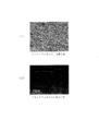
- FIG. 1 is an SEM image of the aluminum material B used in the examples, where (I) is a secondary electron image and (II) is a reflected electron image.
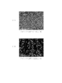
- FIG. 2 is an SEM image of the aluminum material C used in the examples, where (I) is a secondary electron image and (II) is a reflected electron image.
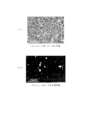
- FIG. 3 is an SEM image of the aluminum material D used in the examples, where (I) is a secondary electron image and (II) is a reflected electron image.
- FIG. 4 is an SEM image of the aluminum material E used in the examples, where (I) is a secondary electron image and (II) is a reflected electron image.
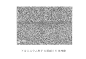
- FIG. 5 is a cross-sectional SEM image of the aluminum material F used in the examples.
- test aluminum material (Aluminum material A) After degassing the molten metal having the composition shown in Table 1, a slab was cast by a DC casting method and finished to a sheet thickness of 0.35 mm by hot rolling and cold rolling. A board was prepared.
- This high-purity aluminum plate was cut into a size of 30 mm ⁇ 60 mm, immersed in an alkaline bath (bath temperature 50 ° C.) of 5% by mass sodium hydroxide for 0.5 minutes, subjected to alkali treatment, washed with water, and further washed with 30 It was immersed in an acid bath (mass temperature 25 ° C.) of mass% nitric acid for 0.5 minutes to remove smut, washed with water and dried to obtain an aluminum material A for testing.
- an alkaline bath bath temperature 50 ° C.
- mass% nitric acid for 0.5 minutes to remove smut
- Al alloy material B After degassing the molten metal having the composition shown in Table 1, a thin slab was cast by a twin belt casting method. This thin slab is cold-rolled with a cold-rolling roll, continuously annealed (CAL) held at 450 ° C. for 30 seconds, and further cold-rolled to a sheet thickness of 0.15 mm. The total cold rolling rate was set to 95% to obtain an aluminum alloy sheet.
- Table 3 shows the production conditions of the aluminum alloy plate in each production process. The aluminum alloy plate corresponds to a 3000 series type aluminum alloy in JIS designation.
- the obtained aluminum alloy plate was cut into a size of 30 mm ⁇ 60 mm, immersed in an alkaline bath (bath temperature 50 ° C.) of 5 mass% sodium hydroxide solution for 0.5 minutes, subjected to alkali treatment, and washed with water. Further, immerse in an acidic bath of 30% by mass nitric acid (bath temperature 25 ° C.) for 0.5 minutes to remove smut, wash with water, and further immerse in an acidic bath of 50% by mass sulfuric acid (bath temperature 70 ° C.) for 2 minutes. Acid treatment was performed. And after performing these chemical treatments, it washed with water again and dried, and the aluminum material B for a test was obtained.
- an alkaline bath bath of 5 mass% sodium hydroxide solution for 0.5 minutes
- an acidic bath of 30% by mass nitric acid bath of 30% by mass nitric acid (bath temperature 25 ° C.) for 0.5 minutes to remove smut, wash with water, and further immerse in an
- the obtained aluminum material B was examined for the number of second-phase particles of the aluminum material having a circle-equivalent radius of 0.1 m or more, the maximum valley depth Rv, and the surface roughness Ra observed on the surface.
- the film formation target surfaces having the properties shown in Table 2 were provided.
- Alkali material C Using the molten metal having the composition shown in Table 1, an aluminum alloy plate is obtained in the same manner as the aluminum material B, cut into a size of 30 mm ⁇ 60 mm, and subjected to alkali treatment with an aqueous sodium hydroxide solution and smut removal with nitric acid. After performing, it washed with water and dried without performing the process by a sulfuric acid, and the aluminum material C for a test was obtained.
- Table 3 shows the production conditions of the aluminum alloy plate in each production process.
- the aluminum alloy plate corresponds to a 3000 series type aluminum alloy in JIS designation.
- the number of second phase particles of the aluminum material having an equivalent circle radius of 0.1 ⁇ m or more, the maximum valley depth Rv, and the surface roughness Ra observed on the surface of the aluminum material C were examined.
- the film formation target surfaces having the properties shown in Table 2 were provided.
- Al alloy material D After degassing the molten metal having the composition shown in Table 1, a slab was cast by a DC casting method, and an aluminum alloy plate finished to a thickness of 3.0 mm by hot rolling and cold rolling was prepared.
- This aluminum alloy plate corresponds to a 5000 series type aluminum alloy in JIS designation.
- This alloy plate was cut into a size of 30 mm ⁇ 60 mm, immersed in an alkali bath (bath temperature 50 ° C.) of 5% by mass aqueous sodium hydroxide for 0.5 minutes for alkali treatment, washed with water, and further 30% by mass. It was immersed in an acidic bath of nitric acid (bath temperature 25 ° C.) for 0.5 minutes to remove smut, washed with water, and further immersed in an acidic bath of 50% by weight sulfuric acid (bath temperature 70 ° C.) for 2 minutes for acid treatment. . And after performing these chemical treatments, it washed with water again and dried, and the aluminum material D for a test was obtained.
- an alkali bath bath temperature 50 ° C.
- nitric acid bath temperature 25 ° C.
- sulfuric acid bath temperature 70 ° C.
- Alkali material E Using the molten metal having the composition shown in Table 1, an aluminum alloy plate is obtained in the same manner as the aluminum material D, cut into a size of 30 mm ⁇ 60 mm, alkali treatment with an aqueous sodium hydroxide solution and smut removal with nitric acid. After performing, it washed with water and it dried without performing the process by a sulfuric acid, and obtained the aluminum material E for a test.
- Table 3 shows the production conditions of the aluminum alloy plate in each production process.
- the aluminum alloy plate corresponds to a 5000 series type aluminum alloy in JIS designation.
- the number of second-phase particles of the aluminum material having an equivalent circle radius of 0.1 ⁇ m or more observed on the surface, the maximum valley depth Rv of the surface, and the surface roughness Ra were examined.
- the film formation target surfaces having the properties shown in Table 2 were provided.
- Alkali material F (Aluminum material F) Using the molten metal having the composition shown in Table 1, an aluminum alloy plate is obtained in the same manner as the aluminum material D, cut into a size of 30 mm ⁇ 60 mm, alkali treatment with an aqueous sodium hydroxide solution and smut removal with nitric acid. After performing, it washed with water and it dried without performing the process by a sulfuric acid, and obtained the aluminum material F for a test. Table 3 shows the production conditions of the aluminum alloy plate in each production process. The aluminum alloy plate corresponds to a 3000 series type aluminum alloy in JIS designation.
- the obtained aluminum material F was examined for the number of second-phase particles of the aluminum material having an equivalent circle radius of 0.1 ⁇ m or more, the maximum valley depth Rv, and the surface roughness Ra observed on the surface of the obtained aluminum material F.
- the film formation target surfaces having the properties shown in Table 2 were provided.
- the second phase particles of the aluminum material having a circle-equivalent radius of 0.1 ⁇ m or more observed on these surfaces are selected at an arbitrary location of approximately 30 ⁇ m ⁇ 40 ⁇ m.
- the 3000-fold backscattered electron image obtained by observing the above area with a scanning electron microscope ULTRA plus made by Carl Zeiss at an acceleration voltage of 3 kV, a working distance of 8 mm, and an aperture of 120 ⁇ m was binarized and image analysis software (Image-Pro) The number was measured.
- a Bruker AXS optical interference microscope (GT-1) is used to measure the maximum valley depth Rv of the surface, and a field of view of approximately 50 ⁇ m ⁇ 50 ⁇ m is selected from the surface of each aluminum material with a 115 ⁇ objective lens. Measured. At that time, the unevenness in the measurement visual field was smoothed (averaged), and the maximum valley depth Rv from the flat reference surface was calculated. Furthermore, the surface roughness Ra of each aluminum material was measured with a 60 ⁇ lens using a laser microscope (LASER MICROSCOPE 1LM21) manufactured by Lasertec to obtain the arithmetic average roughness.
- LASER MICROSCOPE 1LM21 laser microscope manufactured by Lasertec
- each aluminum plate (aluminum alloy plate) used in obtaining the aluminum materials A to F the second phase particles of the aluminum material that they have are identified, and the second phase particles are dissolved in alkali. Whether it is soluble in acid (sulfuric acid) or insoluble in either acid (sulfuric acid) or alkali.
- an X-ray diffractometer RAD-rR manufactured by Rigaku Corporation was used to fix each aluminum plate (aluminum alloy plate) to a sample holder (sample part 24 mm ⁇ ) and identify the components contained in the second phase particles. The above classification was performed. The results are shown in Table 4.
- FIGS. 1 to 4 show SEM images obtained by observing the surfaces of aluminum materials B to E (magnification 3000 times).
- (I) is a secondary electron image
- (II) is a reflected electron image
- (I) and (II) are obtained by observing the same part of the aluminum material surface.
- Information of the surface shape of the sample is obtained from the secondary electron image
- information of the composition of the sample is obtained from the reflected electron image of (II).
- the aluminum material B in FIG. 1 and the aluminum material C in FIG. 2 are essentially the same manufacturing method until cold rolling, whereas in B, the sulfuric acid treatment is performed in addition to the alkali treatment and smut removal. In C, only alkali treatment and smut removal are performed, and sulfuric acid treatment is not performed. Regarding these differences, first, referring to FIG. 2, in (II), many fine second-phase particles (white ones) with a circle-equivalent radius of about 0.1 to 0.7 ⁇ m are confirmed. On the other hand, the second phase particles are not confirmed from FIG. This is presumably because the second phase particles were dissolved in the aluminum material B by the sulfuric acid treatment.
- FIG. 1I shows that the pits (dents) on the surface of the aluminum material B confirmed in FIG. 1I are traces of the dissolution of the second phase particles.
- FIG. 2 (I) shows that a lot of fine second-phase particles exist on the surface of the aluminum material C.
- the second phase particles observed on the surface after the alkali treatment have a circle-equivalent radius of about 0.1 to 0.7 ⁇ m, which is smaller than that of the aluminum material of FIG. 4.
- E it is confirmed that the second phase particles observed on the surface after the alkali treatment are large and have a circle-equivalent radius of about 0.8 to 1.0 ⁇ m.
- the aluminum material D which is the same manufacturing method until cold rolling and is further subjected to sulfuric acid treatment, as can be seen from FIG. 3 (II), such large second phase particles are not confirmed, but these are dissolved.
- large and deep pits (dents) exceeding 2 ⁇ m are formed as shown in FIG.
- FIG. 5 shows a cross-sectional SEM image of the aluminum material F.
- the aluminum material F has only the second phase particles dissolved in the alkaline aqueous solution on the surface. Then, as can be confirmed by this cross-sectional SEM image, after the chemical treatment with the alkaline aqueous solution, the dent of the trace where the second phase particles are dissolved becomes a gentle dimple shape, and the peripheral edge in the opening of the dent is in the shape of a snow flake. It turns out that it is difficult to become.
- the size of the second phase particles themselves can be made finer by making the cast structure fine in advance by the twin belt casting method, as in aluminum materials B and C.
- the surface of the aluminum material according to the present invention can be obtained.
- dissolved by an alkali treatment on the surface like the aluminum material F the aluminum material which has a favorable film-forming object surface can be obtained. Further, the same film formation target surface can be obtained for a high-purity aluminum material having a purity of 99.99% or more like the aluminum material A.
- test aluminum materials A to F obtained above dry conductive films were formed on the respective film formation target surfaces as described below to obtain test conductive members A to F.
- the film formation target surface of the aluminum material A was the upper surface.
- Ring-shaped Pt was used as the sputtering target material, and the height of the sample stage was adjusted so that the distance between the film formation target surface of the aluminum material A and the lower surface of the sputtering target was 35 mm.
- the internal pressure of the vacuum chamber containing the sample stage is evacuated so that the internal pressure is 5 Pa or less, plasma is generated in the chamber so as to obtain a direct current of 15 mA, and a total of 20 minutes is discharged.
- a Pt sputtered film was formed on the entire surface of the film to obtain a test conductive member A.
- the film thickness of the Pt sputtered film formed on the slide glass under the same conditions was measured, it was about 0.1 ⁇ m.
- Pt sputtered films having a thickness of about 0.1 ⁇ m were formed on the test aluminum materials B to F, respectively, to obtain test conductive members B to F.
- test conductive members A to F The corrosion resistance of the test conductive members A to F produced as described above was evaluated by the following method. First, masking was performed using a Teflon (registered trademark) tape so that the Pt sputtering film formation target surface of the test conductive member A was exposed at 1 cm square. Next, the conductive member A was immersed in a 0.5 mol / L aqueous sulfuric acid solution maintained at 27 ° C. in a glass electrochemical cell to obtain a working electrode. A platinum plate was used as the counter electrode, a saturated calomel electrode as the reference electrode, and anodic polarization was performed from a natural potential using an electrochemical measurement system (HZ-3000 manufactured by Hokuto Denko).
- HZ-3000 electrochemical measurement system manufactured by Hokuto Denko
- the potential of 0.6 V on the basis of the saturated calomel electrode is around 0.84 V on the basis of the hydrogen electrode. This is about the same as the actual power generation voltage at the time of fuel cell power generation (single cell, about 0.5 Acm 2 ), and can be said to be an appropriate potential setting.
- the theoretical electromotive force of the single cell is 1.12V
- the voltage is reduced to about 0.8V due to the ohmic loss due to the resistance of members such as the separator and MEA and the reaction resistance of the fuel cell itself.
Landscapes
- Chemical & Material Sciences (AREA)
- Engineering & Computer Science (AREA)
- Mechanical Engineering (AREA)
- Materials Engineering (AREA)
- Organic Chemistry (AREA)
- Metallurgy (AREA)
- Chemical Kinetics & Catalysis (AREA)
- General Chemical & Material Sciences (AREA)
- Manufacturing & Machinery (AREA)
- Electrochemistry (AREA)
- Life Sciences & Earth Sciences (AREA)
- Sustainable Development (AREA)
- Sustainable Energy (AREA)
- Physics & Mathematics (AREA)
- Thermal Sciences (AREA)
- Crystallography & Structural Chemistry (AREA)
- ing And Chemical Polishing (AREA)
- Fuel Cell (AREA)
- Laminated Bodies (AREA)
- Physical Vapour Deposition (AREA)
- Cleaning And De-Greasing Of Metallic Materials By Chemical Methods (AREA)
- Non-Insulated Conductors (AREA)
Abstract
コスト性に優れると共に、高い耐食性を備えて長期に亘る信頼性に優れたアルミニウム製導電部材、及びその製造方法を提供する。 アルミニウム又はアルミニウム合金からなるアルミニウム材の表面に導電膜が成膜されたアルミニウム製導電部材であって、アルミニウム材は、表面で観察される円相当半径0.1μm以上の当該アルミニウム材の第二相粒子が実質的に存在しないと共に、表面の最大谷深さRvが0.1~1.5μmである成膜対象面を有しており、当該成膜対象面に対して、乾式法により厚さ0.1~2μmの乾式導電膜を成膜してアルミニウム製導電部材とする。
Description
この発明は、アルミニウム製導電部材、及びその製造方法に関し、詳しくは、燃料電池のセパレータや集電板をはじめ、例えば、リチウムイオン電池やキャパシタ等で使用される集電箔やタブリード材、電気自動車やハイブリッド自動車用のバスバーなど、各種の導電部材として用いることができるアルミニウム製導電部材、及びその製造方法に関する。
例えば、燃料電池のセパレータや集電板では、導電性に優れることに加えて、高い耐食性が求められる。一般に、燃料電池では80℃程度の高温で湿潤な環境に晒され、正極セパレータを例にとれば、標準水素電極基準で1V付近の正の電位がかかり、極めて厳しい腐食環境におかれることになる。
このような環境で耐食性を有する金属は、専ら、金や白金族のような貴な金属であり、金属製のセパレータや集電板を作製するには、これらの貴金属のめっき浴に鉄やアルミニウム等のような貴な金属基材を浸漬させるなどして、金属基材の表面に貴金属をコーティングして耐食性導電膜を設けることが一般に採用されている。
ところが、高価な貴金属のコーティングを行うと、当然のことながらセパレータや集電板のコストが高くなってしまう。特に、燃料電池自動車で使用されるようなスタックを形成するためには、セパレータであれば数百枚程度を必要とすることから、燃料電池を広く普及させるにあたり、コスト性の改善が求められる。仮に、コストを下げるために貴金属コーティングの膜厚を薄くすると、コーティングにピンホールが含まれてしまい、金属基材が腐食してしまう。
また、これら従来の貴金属コーティングでは、いわゆる湿式めっきが主に採用され、下地にNiめっき皮膜を設けた上でAuめっき皮膜を形成するなど、多段階の工程を経て行われる。また、湿式めっきでは大量の廃液を発生させてしまうため、環境面での対応が必要となる。そのため、このような湿式法にかわる手段の検討がなされている。
例えば、純アルミニウムの粉末を圧縮成形して、大きさ5μm以下の空隙が3体積%以下のセパレータ基体に対して、ダイヤモンドライクカーボン(DLC)等を蒸着させた燃料電池用セパレータがある(特許文献1参照)。このような蒸着膜では(実施例では膜厚1μm)、貴金属を使用しないことからコストを抑えることができる。しかしながら、純アルミニウムの粉末を圧縮成形してセパレータ基体を得るとなると、鋳造したスラブを圧延したアルミニウム板に比べてコストが掛かってしまい、また、機械的強度も劣るおそれがある。
一方で、鉄やアルミニウム等からなるセパレータ基材の表面に、放電プラズマCVDにより導電性のDLC被膜を形成した燃料電池用セパレータがある(特許文献2参照)。先の場合と同様、貴金属を使用しないことからコスト性で有利であるが、DLCは貴金属に比べて体積抵抗が高いため、膜厚を薄くする必要がある。ところが、膜厚を薄くした場合にはピンホールの発生により、セパレータ基材の腐食が問題となってしまう。
なお、この先行技術に係る方法では、5000系のアルミニウム合金材板に厚さ150nmのDLC被膜と厚さ260nmのクロムオキシカーバイド被膜とを積層させることで耐食性に問題がなかったとし(特許文献2の実施例2を参照)、また、アルミニウム合金板の場合、仮に積層被膜に微小なピンホールが存在しても、ピンホール部分のアルミニウム合金板は陽極酸化されることから積層被膜の剥離や金属イオンの溶出は起こらないとしているが(同段落0050参照)、実際に燃料電池用セパレータとして繰り返して使用した場合、セパレータ基材の腐食が問題となるおそれを排除することはできない。
上述したように、金属基材の表面に設ける耐食性の導電膜として、例えば、貴金属にかわりダイヤモンドライクカーボン等を用いる場合、DLC等は体積抵抗が大きいことから膜厚を薄くする必要がある。ところが、膜厚が小さくなると耐食性を十分に得ることができず、実用化にあたってはこのようなトレードオフの問題を解消しなければならない。
そこで、本発明者らは、先ず、金属基材としてアルミニウム材を使用した場合における腐食の問題について詳細に検討し、後述するような推測のもと、その要因と考えられるアルミニウム材の第二相粒子に着目した。そして、導電膜との界面となるアルミニウム材の表面でこのような第二相粒子の数を減らし、しかも、アルミニウム材の表面の最大谷深さRvを所定の範囲にすることで、上記のようなトレードオフの問題を解消できることを見出し、本発明を完成させた。
したがって、本発明の目的は、コスト性に優れると共に、高い耐食性を備えて長期に亘る信頼性に優れたアルミニウム製導電部材を提供することにある。
また、本発明の別の目的は、このようなアルミニウム製導電部材を得ることができるアルミニウム製導電部材の製造方法を提供することにある。
また、本発明の別の目的は、このようなアルミニウム製導電部材を得ることができるアルミニウム製導電部材の製造方法を提供することにある。
すなわち、本発明は、アルミニウム又はアルミニウム合金からなるアルミニウム材の表面に導電膜が成膜されたアルミニウム製導電部材であって、アルミニウム材は、表面で観察される円相当半径0.1μm以上の当該アルミニウム材の第二相粒子が実質的に存在しないと共に、表面の最大谷深さRvが0.1~1.5μmである成膜対象面を有しており、当該成膜対象面に成膜された導電膜が、厚さ0.1~2μmの乾式導電膜であることを特徴とするアルミニウム製導電部材である。
また、本発明は、アルミニウム又はアルミニウム合金からなるアルミニウム材の表面に導電膜が成膜されたアルミニウム製導電部材の製造方法であって、アルミニウム材は、表面で観察される円相当半径0.1μm以上の当該アルミニウム材の第二相粒子が実質的に存在しないと共に、表面の最大谷深さRvが0.1~1.5μmである成膜対象面を有しており、乾式法により当該アルミニウム材の成膜対象面に厚さ0.1~2μmの乾式導電膜を形成することを特徴とするアルミニウム製導電部材の製造方法である。
先ず、本発明のアルミニウム製導電部材は、金属基材としてアルミニウム又はアルミニウム合金からなるアルミニウム材を用いるものであるが、一般に、表面に導電膜が成膜されたアルミニウム材で腐食が引き起こされる原因として、本発明者らは次のような推測をしている。
すなわち、アルミニウム材として広く使用されるのは、鋳造したスラブを圧延したアルミニウム板(展伸材)であるが、これらは通常、圧延の際に圧延油が巻き込まれることにより、アルミニウム板にはオイルピットと称される表面凹凸が形成される。仮に、そのまま導電膜を成膜しても成膜不良が生じてしまうことから、導電部材を得るような場合には、アルカリ性水溶液や酸性水溶液を用いたエッチング処理が事前に施される。
すなわち、アルミニウム材として広く使用されるのは、鋳造したスラブを圧延したアルミニウム板(展伸材)であるが、これらは通常、圧延の際に圧延油が巻き込まれることにより、アルミニウム板にはオイルピットと称される表面凹凸が形成される。仮に、そのまま導電膜を成膜しても成膜不良が生じてしまうことから、導電部材を得るような場合には、アルカリ性水溶液や酸性水溶液を用いたエッチング処理が事前に施される。
このようなエッチング処理により、アルミニウム板の表面粗さは算術平均粗さRaで0.2~0.5μm程度となり、また、エッチング処理後のアルミニウム板の表面には第二相粒子が現れてくる。この第二相粒子は、アルミニウム板の種類にもよるが、大きいもので数~数十μm程度あり、このような大きな第二相粒子がアルミニウム板の表面に露出すると、導電膜を成膜する際に、いわゆる庇のような作用をして膜が載らない箇所を形成する。加えて、例えば燃料電池の動作環境では、膜電極複合体(MEA)のイオン交換樹脂に由来するスルホン酸残基の影響で硫酸酸性となる。上記のような第二相粒子の一部には、アルミニウム母材よりも硫酸に溶解し易い種類の化合物が含まれることから、これらは燃料電池の動作環境で溶解してしまう。これらが原因となって導電膜にピンホールを発生させ、ピンホールを通じてアルミニウム板の一部が溶出し、腐食が起こると考えられる。
一方で、酸やアルカリを用いるなどして、アルミニウム板の表面に存在する第二相粒子を取り除くことが考えられるが、上記のような第二相粒子が溶解した跡には大きな窪み(凹み)が形成される。この場合、スパッタリングやプラズマCVD等といった乾式の成膜法では、例えば窪みにプラズマが侵入すると、窪みの壁面に衝突する頻度が増え、プラズマのエネルギーが減衰しやすくなることから、窪みが深くなればなるほど窪みの底面は成膜され難くなる。そのため、その窪みが深く、或いは窪みの縁が雪庇状に突き出したようになると、成膜不良が生じ、ピンホール等を通じてアルミニウム板の腐食が引き起こされることになる。
そこで、本発明においては、導電膜との界面となるアルミニウム材の表面でこのような第二相粒子の数を減らすと共に、アルミニウム材の表面の最大谷深さRvを所定の範囲にするようにする。これにより、導電膜の膜厚をできるだけ薄くして電気抵抗を小さくすることが可能になり、しかも、ピンホールの発生を防いで優れた耐食性が得られるようになる。具体的には、アルミニウム材が、表面で観察される円相当半径0.1μm以上の当該アルミニウム材の第二相粒子が実質的に存在しないと共に、表面の最大谷深さRvが0.1~1.5μm、好ましくは0.2~1.1μmである成膜対象面を備えるようにする。アルミニウム材の表面で観察される第二相粒子の円相当半径が0.1μmを超えると、上述したように導電膜を成膜する際に膜が載らない箇所が形成されたり、導電膜にピンホールが発生して、アルミニウム材の一部が溶出して腐食が起こる。また、アルミニウム材の表面の最大谷深さRvが1.5μmを超えると導電膜の成膜不良が生じ、同様にアルミニウム材の腐食が引き起こされる。一方で、この最大谷深さRvの下限値については、一般に、第二相粒子がアルミニウム材の表面に存在しない箇所で0.1μm程度になることから、これを規定したものである。なお、最大谷深さRvは、JIS B 0601-2001に準拠するものである。
ここで、第二相粒子とは、素材金属のアルミニウム(Al)以外の物質によって相を形成しているものであり、その第二相粒子の観察手段として、好適にはSEMの反射電子像を利用することができる。このような観察によって、素材金属(マトリックス)であるアルミニウムとその第二相粒子とをコントラストの違いから区別することが可能である。そして、表面で観察される円相当半径0.1μm以上の第二相粒子が実質的に存在しないとは、例えば30μm×40μm程度の範囲を3000倍の拡大倍率で観察した場合に、市販の画像解析ソフト(例えばMedia Cybernetics社製 Image-Pro)を使って円相当半径0.1μm以上の第二相粒子が検出されないことであり、これは、第二相粒子の円相当半径0.1μmを最低の大きさとし、これ以下の第二相粒子は無視できることを意味する。
このようなアルミニウム材のひとつとして、アルミニウム材が、鋳造したスラブを圧延した純度99.99%以上の高純度アルミニウム板であって、その表面が上記のような成膜対象面を備えたものが挙げられる。すなわち、純度99.99%以上の高純度アルミニウム板であれば、その表面に円相当半径0.1μm以上の第二相粒子は実質的に存在せず、また、オイルピットを取り除くようなエッチング処理後であっても、表面の最大谷深さRvは上記範囲を満たすことができる。
また、この高純度アルミニウム板については、例えば圧延ロールの表面形状に起因して転写される表面凹凸を減らすようにするなどの目的から、必要に応じて、その表面を電解研磨したり、後述する酸やアルカリを用いた化学的処理を行うのがよく、好ましくは、高純度アルミニウム板の成膜対象面は表面粗さRaが0.01~0.5μmの範囲に調整されるのがよい。なお、表面粗さRaは、JIS B0601:2001に規定される算術平均粗さを表す。
一方で、先の成膜対象面を備えたアルミニウム材として、汎用のアルミニウム合金を用いることができるが、好ましくは、所定の製造条件で得たアルミニウム合金板を用いるのがよい。すなわち、回動する一対のエンドレスベルトを上下に対向して配置し、このエンドレスベルト同士の隙間にアルミニウム合金の溶湯を導入して、冷却しながら連続的に薄スラブにして取り出してコイルに巻き取る双ベルト鋳造法や、冷却水を通じた一対のロールを用いて、同様に薄スラブにして取り出す双ロール鋳造法によって得られたアルミニウム合金板を用いる。これらのような薄スラブ連続鋳造法は、溶湯を連続的に鋳造して得られたスラブを冷間圧延することから、DC鋳造法(半連続鋳造法)に比べて工程が簡単化され、製造コストを削減することができるほか、DC鋳造法では、鋳造時の溶湯の冷却速度が1~十数℃/secと遅いことから、素材金属に晶出する第二相粒子の大きさが数~数十μm程度に成長してしまうのに対し、薄スラブ連続鋳造法では、冷却速度が20~1000℃/secと速く、細かな鋳造組織が得られて、第二相粒子のサイズをより小さくすることができる。
そこで、所定の合金組成を有する溶湯を薄スラブ連続鋳造法における薄スラブ連続鋳造機により厚み2~20mmのスラブに鋳造し、冷間圧延及び焼鈍を施したアルミニウム合金板を用いて、このアルミニウム合金板を酸性水溶液及び/又はアルカリ性水溶液で化学的処理することにより、当該アルミニウム合金板の第二相粒子を溶解させて上記のような成膜対象面を備えたアルミニウム材を得るようにしてもよい。その際、好ましくは、スラブ厚みの1/4の部位における凝固冷却速度を20~1000℃/secにするのがよい。
ここで、先ず、薄スラブ連続鋳造法の一つである双ベルト鋳造法によりアルミニウム合金板を得る際に、例えば、双ベルト式鋳造機は、回動する一対のエンドレスベルトが上下に対向して配置され、このベルト同士に挟まれた平坦な部分に溶湯を導いて、ベルトの回動に合わせて移送させることにより、溶湯が20~200℃/secの冷却速度で冷却され、所望の板厚を有するスラブが連続鋳造されるようになる。このとき、双ベルト式鋳造機で鋳造されたスラブは2~20mm、好ましくは5~15mmの総厚を有するようにする。そして、所定の厚みのスラブに鋳造した後は、熱間圧延を施すことなくロールに巻き取るようにするのがよい。
また、双ロール鋳造法によりアルミニウム合金板を得る際には、双ロール鋳造機は、回動する一対の冷却水を通じたロールが上下に対向して配置され、このロール同士に挟まれた平坦な部分に溶湯を導いて、ロールの回動に合わせて移送させることにより、溶湯が100~1000℃/secの冷却速度で冷却され、所望の板厚を有するスラブが連続鋳造されるようになる。このとき、双ロール式鋳造機で鋳造されたスラブは2~10mm、好ましくは2.5~6mmの総厚を有するようにする。そして、所定の厚みのスラブに鋳造した後は、熱間圧延を施すことなくロールに巻き取るようにするのがよい。
このようにして薄スラブ連続鋳造法により得られたスラブは、冷間圧延と焼鈍を組み合わせて、所定の板厚及び調質のアルミニウム合金板を得るのがよい。これらについては特に制限はないが、冷間圧延は、例えば、圧下率70%以上で圧延するのがよく、焼鈍については、例えば、バッチ炉や連続焼鈍ラインを用いて再結晶温度以上で15秒間以上保持するのがよい。
このようにして薄スラブ連続鋳造法により得られたスラブは、冷間圧延と焼鈍を組み合わせて、所定の板厚及び調質のアルミニウム合金板を得るのがよい。これらについては特に制限はないが、冷間圧延は、例えば、圧下率70%以上で圧延するのがよく、焼鈍については、例えば、バッチ炉や連続焼鈍ラインを用いて再結晶温度以上で15秒間以上保持するのがよい。
これらの薄スラブ連続鋳造法で得るアルミニウム合金板について特に制限はないが、好ましくは、JISの称呼で1000系、3000系、5000系、6000系、又は8000系のアルミニウム合金板であるのがよく、なかでも、燃料電池部材をはじめ、リチウムイオン電池、キャパシタ、電気二重層キャパシタ等に使用される導電部材の場合には、耐食性や成形性に優れた材質であることが必要であることから、より好ましくは1000系、3000系、又は5000系のアルミニウム合金板であるのがよい。
そして、薄スラブ連続鋳造法により得られたアルミニウム合金板は、酸性水溶液及び/又はアルカリ性水溶液を用いて化学的処理することで、そのアルミニウム合金板に含まれる表面の第二相粒子を溶解させる。これらアルミニウム合金板では、その第二相粒子は円相当半径で0.1~0.7μm程度の小さな粒子になっているが、これらをより小さくしたり、減らしたりするために、酸性水溶液及び/又はアルカリ性水溶液を用いてアルミニウム合金板の表面を化学的処理する。ちなみに、化学的処理前のアルミニウム合金板に円相当半径0.75μmの第二相粒子が存在したとして、これが酸やアルカリで溶解すると、理論上は最大でRv=1.5μmの窪みが形成されることになる。従って、アルミニウム合金板は、円相当半径0.75μm以上の第二相粒子が存在しないように微細な鋳造組織が得られているのが良いと言うことができる。
ここで、例えば、1000系のアルミニウム合金板にはAl-FeやAl-Fe-Si系の金属間化合物からなる第二相粒子が存在し、このうち、Al3Feやα-Al(Fe,M)Siは(MはMn、Cr等を示す)、硫酸等の酸に溶けるとされる(軽金属学会 研究部会報告書No.22 「アルミニウム合金の表面処理性に及ぼす金属間化合物の影響」)。同様に、3000系のアルミニウム合金板にはAl-Fe-MnやAl-Fe―Mn-Si系の金属間化合物に加えて、単体Siからなる第二相粒子が存在し、このうち、α-Al(Fe,Mn)Siは、硫酸等の酸に溶け、Al6(Fe,Mn)は水酸化ナトリウム水溶液等のアルカリに溶けるとされる。また、5000系のアルミニウム合金板にはAl-FeやMg-Si系の金属間化合物に加えて、単体Siからなる第二相粒子が存在し、このうち、Mg2Siは、硫酸、硝酸等の酸に溶けると共に、水酸化ナトリウム等のアルカリにも溶ける。また、6000系のアルミニウム合金板にはAl-Fe-SiやMg-Si系の金属間化合物に加えて、単体Siからなる第二相粒子が存在し、このうち、Mg2Siは硫酸、硝酸等の酸に溶けると共に、水酸化ナトリウム水溶液等のアルカリに溶ける。更に、8000系のアルミニウム合金板にはAl-FeやMg-Si系の金属間化合物からなる第二相粒子が存在し、このうち、Al3Feは、硫酸等の酸に溶け、Mg2Siは、硫酸、硝酸等の酸や水酸化ナトリウム等のアルカリに溶ける。
ところで、酸性水溶液を用いた化学的処理によりアルミニウム合金板の表面における第二相粒子を溶解除去する場合、アルミニウム母材に対して第二相粒子が選択的に溶解されやすいことから、アルミニウム合金板の厚さ方向における第二相粒子の存在位置によっては、第二相粒子が溶解した跡の窪み(凹み)の開口部には雪庇状に突き出した縁が形成されてしまうことがある。それに対して、アルカリ性水溶液を用いた化学的処理によってアルミニウム合金板の表面の第二相粒子を溶解除去する場合には、第二相粒子周辺のアルミニウム母材も同時に溶解されやすく、第二相粒子の溶解した跡の窪みが雪庇状に突き出したような開口部は形成され難い(跡の窪みがなだらかなディンプル状になる)。
そのため、好ましくは、アルミニウム合金板の表面に存在する第二相粒子が、いずれもアルカリ性水溶液で溶解するものであるのがよく、具体的には、表面に存在する第二相粒子がいずれもAl6(Fe,Mn)やMg2Si等であって、酸性水溶液による化学的処理を用いずに成膜対象面を形成することができるものであるのがよい。すなわち、少なくとも表面に有する第二相粒子がアルカリ性水溶液による化学的処理で溶解できるものだけであるアルミニウム合金板であれば、表面の第二相粒子を取り除くための化学的処理がアルカリによるものだけですみ、これにより、導電膜の形成に好適なアルミニウム材を得ることができる。
また、アルミニウム合金板中に酸やアルカリに溶解しない種類の第二相粒子が存在する場合、熱処理によって上記のような酸やアルカリに溶解する種類の第二相粒子になるように相変態を起こさせた後に、第二相粒子を溶解除去することも可能である。具体的には、A3004中に存在するAl6(Fe,Mn)はアルカリに溶けるが硫酸には不溶であり、単体Siは酸にもアルカリにも溶けない。しかし、565℃の熱処理により、Al6(Fe,Mn)及び単体Siが、α-Al(Fe,Mn)Siに相変態することが報告されており(軽金属 vol.33, 3, 149(1983))、この熱処理の後に硫酸で処理を行えば、硫酸に溶けるα-Al(Fe,Mn)Siの一種類のみに相変態した第二相粒子を、硫酸処理によってアルミニウム合金板の表面からほぼ完全に除去することができる。
この酸性水溶液及び/又はアルカリ性水溶液を用いた化学的処理の具体的手段については特に制限はなく、例えば、酸性水溶液やアルカリ性水溶液にアルミニウム合金板を浸漬させたり、アルミニウム合金板に噴霧したりする方法等を挙げることができる。また、化学的処理の処理条件としては、酸やアルカリの種類にもよるが、例えば、酸として硫酸を用いる場合には、50質量%程度の濃度にした処理液(水溶液)を50~80℃にして10秒~4分間程度処理するようにすればよい。また、アルカリとして水酸化ナトリウムを用いる場合には、1~10質量%程度の濃度にした処理液(水溶液)を30~60℃にして10秒~4分間程度処理するようにすればよい。このような化学的処理は、アルミニウム合金板の種類に応じて、酸処理やアルカリ処理を適宜組み合わせながら、表面の第二相粒子を溶解させればよく、2種以上の酸処理を組み合わせたり、2種以上のアルカリ処理を組み合わせるようにしてもよい。なお、冷間圧延後のエッチング処理等でアルカリを用いているような場合には、別途酸処理だけを行うようにしてもよい。
このように、薄スラブ連続鋳造法により得られたアルミニウム合金板について、酸やアルカリを用いた化学的処理を施すことで、その表面で観察される円相当半径0.1μm以上の当該アルミニウム合金板の第二相粒子が実質的に存在しないと共に、表面の最大谷深さRvが0.1~1.5μm、好ましくは0.2~1.3μmの成膜対象面を備えるようになる。また、このようなアルミニウム合金板の表面に形成される成膜対象面は、好ましくは表面粗さRaが0.01~0.5μmの範囲であるのがよい。
また、本発明において、所定の成膜対象面を備えたアルミニウム材については、導電部材の種類や用途に応じて、強度を高めたり、導電率を向上するなどの目的から、他の金属部材と接合させてアルミニウムクラッド材としてもよい。すなわち、鋳造したスラブを圧延した純度99.99%以上の高純度アルミニウム板と他の金属部材とを接合させて、高純度アルミニウム板の表面が上記成膜対象面を備えたアルミニウムクラッド材としたり、薄スラブ連続鋳造法で得たアルミニウム合金板と他の金属部材とを接合させ、アルミニウム合金板を化学的処理して、上記成膜対象面を備えたアルミニウムクラッド材としたり、また、表面に存在する第二相粒子が、いずれもアルカリ性水溶液で溶解するものであるアルミニウム合金板と他の金属部材とを接合させ、アルミニウム合金板をアルカリ性水溶液で化学的処理して、上記成膜対象面を備えたアルミニウムクラッド材としてもよい。その際に使用される他の金属部材としては、例えば、鉄、銅、チタン等の金属部材を挙げることができる。
そして、本発明においては、アルミニウム材の成膜対象面に対し、乾式法によって厚さ0.1~2μm、好ましくは0.1~1μmの乾式導電膜を成膜する。上述したように、アルミニウム材の成膜対象面では、円相当半径0.1μm以上の第二相粒子が実質的に存在せず、また、表面の最大谷深さRvが0.1~1.5μmであることから、上記のような膜厚の乾式導電膜を形成することで、ピンホールの発生を防いで導電部材の耐食性を十分に確保することができる。また、乾式導電膜の膜厚を2μm以下にすることで、導電部材としての電気抵抗を小さくすることができる。
本発明における乾式導電膜について、その種類や成膜手段は特に制限されないが、例えば、CVD、スパッタリング、真空蒸着、イオンプレーティング、イオン注入等のような公知の乾式法を用いて成膜することができ、その1種又は2種以上を組み合わせて形成してもよい。すなわち、乾式導電膜としては、CVD膜、スパッタリング膜、真空蒸着膜、イオンプレーティング膜、イオン注入膜等を挙げることができ、好ましくは、導電性炭素膜や貴金属薄膜を形成するのがよい。このうち、コスト性の観点では貴金属薄膜に比べて導電性炭素膜が有利である。なかでも、緻密で耐食性や摺動性に優れることなどから、より好ましくは、ダイヤモンドライクカーボンのようなアモルファスカーボン膜であるのがよい。更には、導電性炭素膜には、ホウ素(B)やアルミニウム、リン、ヒ素等がドープされていてもよい。なお、貴金属薄膜を形成する場合には、耐食性に優れることからAuやPtであるのが望ましいが、これらの金属は高価であることから、その膜厚は0.2μm以下に留めるようにするのがよい。
本発明におけるアルミニウム製導電部材は、高い耐食性を有し、電気抵抗が小さく、実用性に優れたものである。そのため、その用途は特に制限されないが、例えば、セパレータや集電板のような燃料電池部材をはじめ、リチウムイオン電池、キャパシタ等の集電箔やタブリード材、電気自動車やハイブリッド自動車用のバスバー等を挙げることができる。なかでも、高温・湿潤環境で使用しても、ピンホールを通じたアルミニウム材の溶出を防ぐことができ、優れた耐食性を備えることから、燃料電池部材として好適であって、長期に亘って信頼性良く使用することができる。
本発明のアルミニウム製導電部材は、コスト性に優れると共に、高い耐食性を備えており、長期の使用に対して優れた信頼性を備えたものである。また、本発明のアルミニウム製導電部材の製造方法によれば、コストを抑えながら、耐食性に優れたアルミニウム製導電部材を得ることができる。
以下、実施例に基いて本発明をより具体的に説明するが、本発明はこれらの内容に制限されるものではない。
[試験用アルミニウム材の作製]
(アルミニウム材A)
表1に示した組成を有する溶湯を脱ガス鎮静後、DC鋳造法によりスラブを鋳造し、熱間圧延と冷間圧延とにより板厚0.35mmに仕上げた純度99.99%の高純度アルミニウム板を用意した。この高純度アルミニウム板を30mm×60mmの大きさに切り出し、5質量%水酸化ナトリウム水溶液のアルカリ浴(浴温50℃)に0.5分間浸漬させてアルカリ処理を行い、水洗後、更に、30質量%硝酸の酸性浴(浴温度25℃)に0.5分間浸漬させスマット除去し、水洗、乾燥して試験用のアルミニウム材Aを得た。
(アルミニウム材A)
表1に示した組成を有する溶湯を脱ガス鎮静後、DC鋳造法によりスラブを鋳造し、熱間圧延と冷間圧延とにより板厚0.35mmに仕上げた純度99.99%の高純度アルミニウム板を用意した。この高純度アルミニウム板を30mm×60mmの大きさに切り出し、5質量%水酸化ナトリウム水溶液のアルカリ浴(浴温50℃)に0.5分間浸漬させてアルカリ処理を行い、水洗後、更に、30質量%硝酸の酸性浴(浴温度25℃)に0.5分間浸漬させスマット除去し、水洗、乾燥して試験用のアルミニウム材Aを得た。

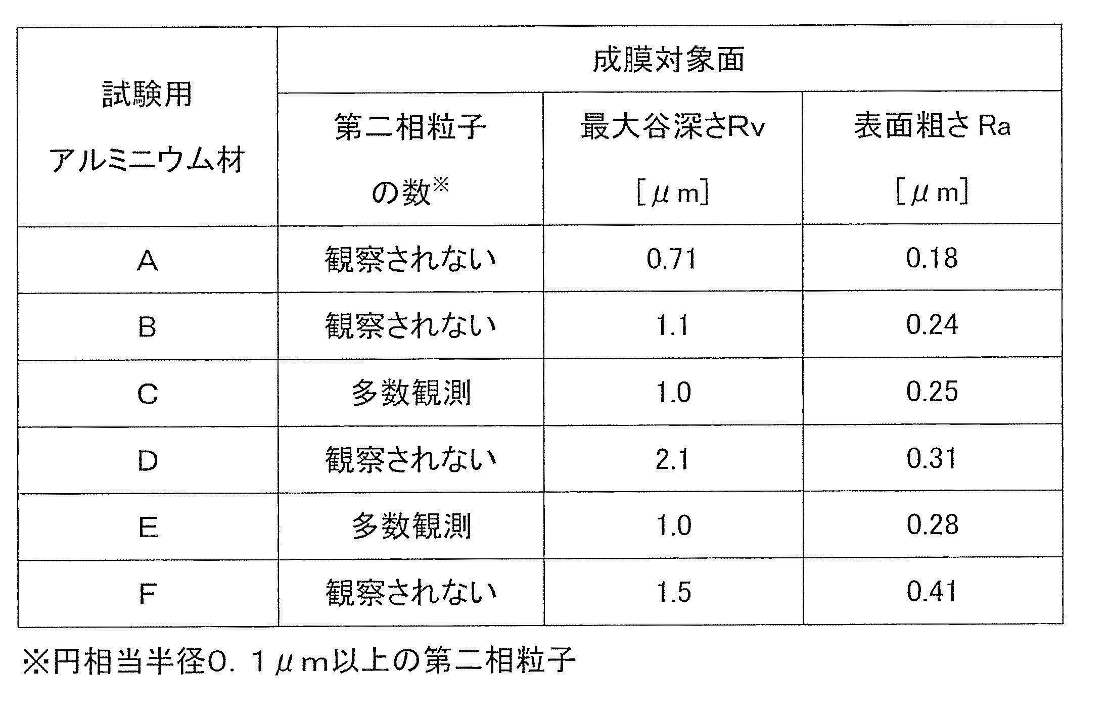
そして、その表面で観察される円相当半径0.1μm以上の当該アルミニウム材の第二相粒子の数、表面の最大谷深さRv、及び表面粗さRaを調べたところ、それぞれ表2に示した性状の成膜対象面を備えていた。なお、表3には、各製造工程におけるアルミニウム板の製造条件を示している。また、第二相粒子の数や表面の最大谷深さRv等の測定の詳細は後述するとおりである。

(アルミニウム材B)
表1に示した組成を有する溶湯を脱ガス鎮静後、双ベルト鋳造法により薄スラブを鋳造した。この薄スラブを冷間圧延ロールで冷間圧延し、450℃で30秒間保持する連続焼鈍(CAL)して、更に、冷間圧延して0.15mmの板厚に仕上ることで、薄スラブからの全冷間圧延率を95%とし、アルミニウム合金板を得た。なお、表3には、各製造工程におけるアルミニウム合金板の製造条件を示している。また、このアルミニウム合金板は、JIS称呼で3000系の種類のアルミニウム合金に相当するものである。
表1に示した組成を有する溶湯を脱ガス鎮静後、双ベルト鋳造法により薄スラブを鋳造した。この薄スラブを冷間圧延ロールで冷間圧延し、450℃で30秒間保持する連続焼鈍(CAL)して、更に、冷間圧延して0.15mmの板厚に仕上ることで、薄スラブからの全冷間圧延率を95%とし、アルミニウム合金板を得た。なお、表3には、各製造工程におけるアルミニウム合金板の製造条件を示している。また、このアルミニウム合金板は、JIS称呼で3000系の種類のアルミニウム合金に相当するものである。
次に、得られたアルミニウム合金板を30mm×60mmの大きさに切り出し、5質量%水酸化ナトリウム水溶液のアルカリ浴(浴温50℃)に0.5分間浸漬させてアルカリ処理を行い、水洗後、更に、30質量%硝酸の酸性浴(浴温度25℃)に0.5分間浸漬させスマット除去し、水洗後、更に50質量%硫酸の酸性浴(浴温70℃)に2分間浸漬して酸処理を行った。そして、これらの化学的処理を行った後、再度水洗、乾燥して、試験用のアルミニウム材Bを得た。得られたアルミニウム材Bについて、その表面で観察される円相当半径0.1m以上の当該アルミニウム材の第二相粒子の数、表面の最大谷深さRv、及び表面粗さRaを調べたところ、それぞれ表2に示した性状の成膜対象面を備えていた。
(アルミニウム材C)
表1に示した組成を有する溶湯を用いて上記アルミニウム材Bと同様にしてアルミニウム合金板を得て、30mm×60mmの大きさに切り出し、水酸化ナトリウム水溶液によるアルカリ処理と硝酸によるスマット除去とを行った後、水洗して、硫酸による処理を行わずに乾燥させて、試験用のアルミニウム材Cを得た。なお、表3には、各製造工程におけるアルミニウム合金板の製造条件を示している。また、このアルミニウム合金板は、JIS称呼で3000系の種類のアルミニウム合金に相当するものである。
表1に示した組成を有する溶湯を用いて上記アルミニウム材Bと同様にしてアルミニウム合金板を得て、30mm×60mmの大きさに切り出し、水酸化ナトリウム水溶液によるアルカリ処理と硝酸によるスマット除去とを行った後、水洗して、硫酸による処理を行わずに乾燥させて、試験用のアルミニウム材Cを得た。なお、表3には、各製造工程におけるアルミニウム合金板の製造条件を示している。また、このアルミニウム合金板は、JIS称呼で3000系の種類のアルミニウム合金に相当するものである。
得られたアルミニウム材Cについて、その表面で観察される円相当半径0.1μm以上の当該アルミニウム材の第二相粒子の数、表面の最大谷深さRv、及び表面粗さRaを調べたところ、それぞれ表2に示した性状の成膜対象面を備えていた。
(アルミニウム材D)
表1に示した組成を有する溶湯を脱ガス鎮静後、DC鋳造法によりスラブを鋳造し、熱間圧延と冷間圧延とにより板厚3.0mmに仕上げたアルミニウム合金板を用意した。このアルミニウム合金板は、JIS称呼で5000系の種類のアルミニウム合金に相当するものである。
表1に示した組成を有する溶湯を脱ガス鎮静後、DC鋳造法によりスラブを鋳造し、熱間圧延と冷間圧延とにより板厚3.0mmに仕上げたアルミニウム合金板を用意した。このアルミニウム合金板は、JIS称呼で5000系の種類のアルミニウム合金に相当するものである。
この合金板を30mm×60mmの大きさに切り出し、5質量%水酸化ナトリウム水溶液のアルカリ浴(浴温50℃)に0.5分間浸漬させてアルカリ処理を行い、水洗後、更に、30質量%硝酸の酸性浴(浴温度25℃)に0.5分間浸漬させスマット除去し、水洗後、更に、50質量%硫酸の酸性浴(浴温70℃)に2分間浸漬して酸処理を行った。そして、これらの化学的処理を行った後、再度水洗、乾燥して、試験用のアルミニウム材Dを得た。そして、その表面で観察される円相当半径0.1μm以上の当該アルミニウム材の第二相粒子の数、表面の最大谷深さRv、及び表面粗さRaを調べたところ、それぞれ表2に示した性状の成膜対象面を備えていた。なお、表3には、各製造工程におけるアルミニウム板の製造条件を示している。
(アルミニウム材E)
表1に示した組成を有する溶湯を用いて上記アルミニウム材Dと同様にしてアルミニウム合金板を得て、30mm×60mmの大きさに切り出し、水酸化ナトリウム水溶液によるアルカリ処理と硝酸によるスマット除去とを行った後、水洗して、硫酸による処理を行わずに乾燥させて、試験用のアルミニウム材Eを得た。なお、表3には、各製造工程におけるアルミニウム合金板の製造条件を示している。また、このアルミニウム合金板は、JIS称呼で5000系の種類のアルミニウム合金に相当するものである。
表1に示した組成を有する溶湯を用いて上記アルミニウム材Dと同様にしてアルミニウム合金板を得て、30mm×60mmの大きさに切り出し、水酸化ナトリウム水溶液によるアルカリ処理と硝酸によるスマット除去とを行った後、水洗して、硫酸による処理を行わずに乾燥させて、試験用のアルミニウム材Eを得た。なお、表3には、各製造工程におけるアルミニウム合金板の製造条件を示している。また、このアルミニウム合金板は、JIS称呼で5000系の種類のアルミニウム合金に相当するものである。
得られたアルミニウム材Eについて、その表面で観察される円相当半径0.1μm以上の当該アルミニウム材の第二相粒子の数、表面の最大谷深さRv、及び表面粗さRaを調べたところ、それぞれ表2に示した性状の成膜対象面を備えていた。
(アルミニウム材F)
表1に示した組成を有する溶湯を用いて上記アルミニウム材Dと同様にしてアルミニウム合金板を得て、30mm×60mmの大きさに切り出し、水酸化ナトリウム水溶液によるアルカリ処理と硝酸によるスマット除去とを行った後、水洗して、硫酸による処理を行わずに乾燥させて、試験用のアルミニウム材Fを得た。なお、表3には、各製造工程におけるアルミニウム合金板の製造条件を示している。また、このアルミニウム合金板は、JIS称呼で3000系の種類のアルミニウム合金に相当するものである。
表1に示した組成を有する溶湯を用いて上記アルミニウム材Dと同様にしてアルミニウム合金板を得て、30mm×60mmの大きさに切り出し、水酸化ナトリウム水溶液によるアルカリ処理と硝酸によるスマット除去とを行った後、水洗して、硫酸による処理を行わずに乾燥させて、試験用のアルミニウム材Fを得た。なお、表3には、各製造工程におけるアルミニウム合金板の製造条件を示している。また、このアルミニウム合金板は、JIS称呼で3000系の種類のアルミニウム合金に相当するものである。
得られたアルミニウム材Fについて、その表面で観察される円相当半径0.1μm以上の当該アルミニウム材の第二相粒子の数、表面の最大谷深さRv、及び表面粗さRaを調べたところ、それぞれ表2に示した性状の成膜対象面を備えていた。
ここで、上記で得られたアルミニウム材A~Fについて、これらの表面で観察される円相当半径0.1μm以上の当該アルミニウム材の第二相粒子は、任意の場所を選んでおよそ30μm×40μmの領域を、カールツァイス社製走査型電子顕微鏡ULTRA plusを用いて加速電圧3kV、作動距離8mm、アパーチャー120μmで観察した3000倍の反射電子画像を二値化し、画像解析ソフト(Image-Pro)によりその数を測定した。また、表面の最大谷深さRvの測定にはブルカーAXS社製の光干渉顕微鏡(GT-1)を使用し、115倍の対物レンズで各アルミニウム材の表面からおよそ50μm×50μmの視野を選び出して測定した。その際、測定視野内の凹凸をスムージング(平均化)処理し、フラットな基準面からの最大谷深さRvを算出した。更に、各アルミニウム材の表面粗さRaは、レーザーテック社製のレーザー顕微鏡(LASER MICROSCOPE 1LM21)を用いて60倍のレンズで測定して、算術平均粗さを求めた。
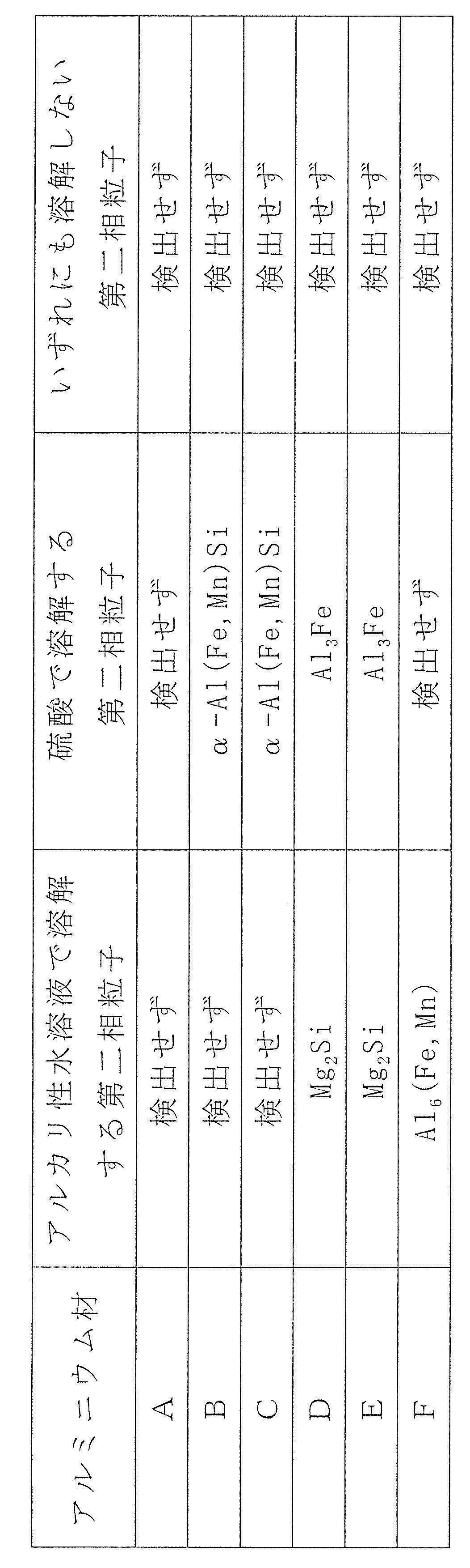
また、アルミニウム材A~Fを得る際に用いたそれぞれのアルミニウム板(アルミニウム合金板)について、それらが有する当該アルミニウム材の第二相粒子を同定し、その第二相粒子がアルカリに溶解するものであるのか、酸(硫酸)に溶解するものであるのか、酸(硫酸)とアルカリのいずれにも溶解しないものであるのかを分類した。これらの分類にあたっては株式会社リガク製のX線回折装置RAD-rRを用い、各アルミニウム板(アルミニウム合金板)をサンプルホルダ(試料部24mmφ)に固定して第二相粒子の含有成分を同定し、上記の分類を行った。結果を表4に示す。
そして、図1~4には、アルミニウム材B~Eについて、表面を観察したSEM画像が示されている(倍率3000倍)。図1~4のいずれも(I)が二次電子像、(II)が反射電子像であり、(I)と(II)はアルミニウム材表面の同じ個所を観察したものであるが、(I)の二次電子像から試料の表面形状の情報が得られ、(II)の反射電子像からは試料の組成の情報が得られる。
このうち、図1のアルミニウム材Bと図2のアルミニウムC材では、冷間圧延まで本質的に同じ製法であるが、Bではアルカリ処理とスマット除去に加えて硫酸処理まで行っているのに対し、Cではアルカリ処理とスマット除去のみであり、硫酸処理は行っていない。これらの違いに関し、先ず、図2を見ると、(II)には円相当半径が0.1~0.7μm程度の細かな第二相粒子(白く写ったもの)が数多く確認されるのに対し、図1(II)から第2相粒子は確認されない。これは、アルミニウム材Bでは硫酸処理により第二相粒子が溶解したためと考えられる。つまり、図1(I)で確認されるアルミニウム材Bの表面のピット(窪み)は、第二相粒子が溶解した跡である。一方の図2(I)からは、アルミニウム材Cの表面に細かな第二相粒子が数多く存在していることが分かる。
また、上記のとおり、図2ではアルカリ処理後に表面で観察される第二相粒子の円相当半径は0.1~0.7μm程度と細かな粒子であるのに比べて、図4のアルミニウム材Eでは、アルカリ処理後に表面で観察される第二相粒子は、大きなもので円相当半径が0.8~1.0μm程度のものが確認される。そして、冷間圧延まで同じ製法であって、更に硫酸処理を施しているアルミニウム材Dでは、図3(II)から分かるように、このような大きな第二相粒子は確認されないが、これらが溶解したアルミニウム材Dの表面には、図3(I)に示されているように、2μmを超える大きくて深いピット(窪み)が形成される。
また、図5には、アルミニウム材Fの断面SEM画像が示されている。アルミニウム材Fでは、表4に示されるとおり、アルカリ性水溶液で溶解する第二相粒子のみを表面に有している。そして、この断面SEM画像で確認できるように、アルカリ性水溶液による化学的処理の後には、第二相粒子の溶解した跡の窪みがなだらかなディンプル状となり、窪みの開口部における周辺の縁が雪庇状になり難いことが分かる。
これらの結果からも分かるように、アルミニウム材BやCのように、双ベルト鋳造法により予め鋳造組織を微細にしておくことで、第二相粒子自体の大きさも細かくすることができ、それに加えて、これらの第二相粒子を溶解させる酸やアルカリを用いた化学的処理を行うことで、本発明に係るアルミニウム材の成膜対象面を得ることができる。また、アルミニウム材Fのように、アルカリ処理で溶解できる第二相粒子のみを表面に有するアルミニウム合金板を用いる場合にも、良好な成膜対象面を有するアルミニウム材を得ることができる。更には、アルミニウム材Aのように純度99.99%以上の高純度アルミニウム材についても同様の成膜対象面を得ることができる。
[試験用導電部材の作製]
上記で得られた試験用アルミニウム材A~Fについて、それぞれの成膜対象面に以下のようにして乾式導電膜を成膜して、試験用導電部材A~Fを得た。
先ず、イオンスパッタ装置(日立那珂精器社製E-102)の試料台の上に、アルミニウム材Aの成膜対象面が上面となるよう静置した。スパッタターゲット材にはリング状Ptを用い、アルミニウム材Aの成膜対象面とスパッタターゲットの下面との距離が35mmとなるように試料台の高さを調整した。次いで、試料台を収めた真空チャンバーの内圧を5Pa以下となるように真空引きし、直流15mAの放電電流となるようチャンバー内にプラズマを発生させ、合計20分間放電させて、アルミニウム材Aの成膜対象面全面にPtスパッタ膜を成膜し、試験用導電部材Aを得た。その際、同様の条件でスライドガラス上に成膜したPtスパッタ膜の膜厚を計測したところ、約0.1μmであった。以下同様にして、試験用アルミニウム材B~Fに対してそれぞれ厚さ約0.1μmのPtスパッタ膜を成膜して、試験用導電部材B~Fを得た。
上記で得られた試験用アルミニウム材A~Fについて、それぞれの成膜対象面に以下のようにして乾式導電膜を成膜して、試験用導電部材A~Fを得た。
先ず、イオンスパッタ装置(日立那珂精器社製E-102)の試料台の上に、アルミニウム材Aの成膜対象面が上面となるよう静置した。スパッタターゲット材にはリング状Ptを用い、アルミニウム材Aの成膜対象面とスパッタターゲットの下面との距離が35mmとなるように試料台の高さを調整した。次いで、試料台を収めた真空チャンバーの内圧を5Pa以下となるように真空引きし、直流15mAの放電電流となるようチャンバー内にプラズマを発生させ、合計20分間放電させて、アルミニウム材Aの成膜対象面全面にPtスパッタ膜を成膜し、試験用導電部材Aを得た。その際、同様の条件でスライドガラス上に成膜したPtスパッタ膜の膜厚を計測したところ、約0.1μmであった。以下同様にして、試験用アルミニウム材B~Fに対してそれぞれ厚さ約0.1μmのPtスパッタ膜を成膜して、試験用導電部材B~Fを得た。
上記のようにして作製した試験用導電部材A~Fについて、以下の方法で耐食性を評価した。
先ず、試験用導電部材AのPtスパッタ成膜対象面が1cm角で露出するようにテフロン(登録商標)テープを用いてマスキングを施した。次いで、この導電部材Aをガラス製の電気化学セル中で27℃に保持した0.5mol/Lの硫酸水溶液に浸漬し、作用極とした。対極に白金板、参照極には飽和カロメル電極を用い、電気化学測定システム(北斗電工社製 HZ-3000)を用いて自然電位からアノード分極を行った。そして、飽和カロメル電極基準で0.6Vの時のアノード電流値の多寡で耐食性の判定を行い、100μA/cm2を超えたものを耐食性不足で不合格とし、100μA/cm2を下回ったものを合格とした。同様にして、試験用導電部材B~Eについてもアノード電流値を求めて耐食性を評価した。結果をまとめて表5に示す。
先ず、試験用導電部材AのPtスパッタ成膜対象面が1cm角で露出するようにテフロン(登録商標)テープを用いてマスキングを施した。次いで、この導電部材Aをガラス製の電気化学セル中で27℃に保持した0.5mol/Lの硫酸水溶液に浸漬し、作用極とした。対極に白金板、参照極には飽和カロメル電極を用い、電気化学測定システム(北斗電工社製 HZ-3000)を用いて自然電位からアノード分極を行った。そして、飽和カロメル電極基準で0.6Vの時のアノード電流値の多寡で耐食性の判定を行い、100μA/cm2を超えたものを耐食性不足で不合格とし、100μA/cm2を下回ったものを合格とした。同様にして、試験用導電部材B~Eについてもアノード電流値を求めて耐食性を評価した。結果をまとめて表5に示す。
なお、飽和カロメル電極基準で0.6Vの電位は、水素電極基準では0.84V付近となる。これは燃料電池の発電時(単セル、0.5Acm2程度)の実際の発電電圧と同程度であり、妥当な電位設定と言える。ちなみに、単セルの理論起電力は1.12Vであるが、セパレータやMEA等の部材の抵抗や燃料電池自体の反応抵抗によるオーム損により電圧が0.8V程度に低下する。
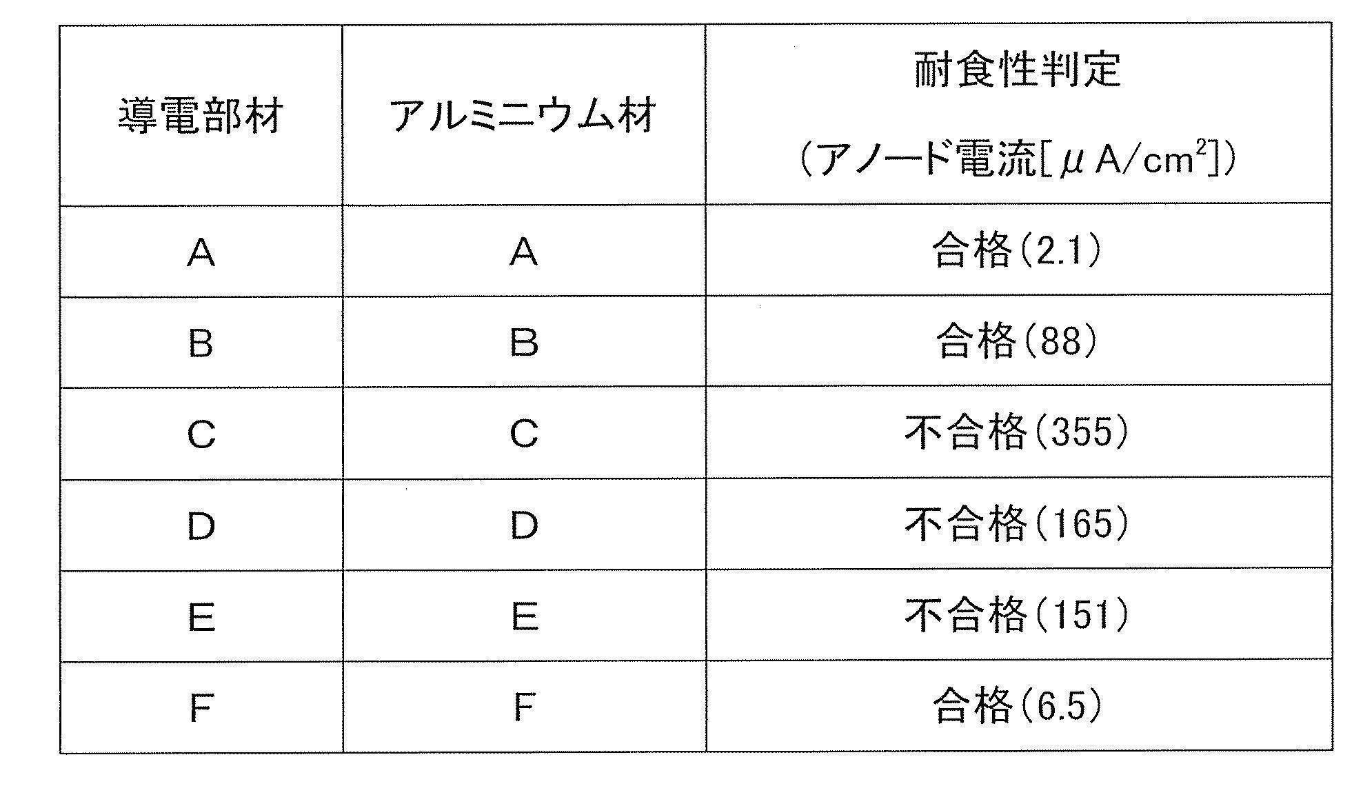
上記結果から分かるように、本発明に係る成膜対象面を備えたアルミニウム材A、B及びFによれば、耐食性に優れた導電部材を得ることができる。それに対して、所定のサイズを超える第二相粒子が成膜対象面に存在するアルミニウム材CやEや、大きな(深い)窪みを有するアルミニウム材Dの場合には、耐食性に優れた導電部材を得ることができない。
Claims (18)
- アルミニウム又はアルミニウム合金からなるアルミニウム材の表面に導電膜が成膜されたアルミニウム製導電部材であって、
アルミニウム材は、表面で観察される円相当半径0.1μm以上の当該アルミニウム材の第二相粒子が実質的に存在しないと共に、表面の最大谷深さRvが0.1~1.5μmである成膜対象面を有しており、当該成膜対象面に成膜された導電膜が、厚さ0.1~2μmの乾式導電膜であることを特徴とするアルミニウム製導電部材。 - アルミニウム材が、所定の合金組成を有する溶湯を薄スラブ連続鋳造機により厚み2~20mmのスラブに鋳造し、冷間圧延及び焼鈍を施して得たアルミニウム合金板を用いたものであり、酸性水溶液及び/又はアルカリ性水溶液を用いた化学的処理により当該アルミニウム合金板の第二相粒子を溶解させて前記成膜対象面が形成される請求項1に記載のアルミニウム製導電部材。
- アルミニウム合金板の表面に存在する第二相粒子が、いずれもアルカリ性水溶液で溶解するものである請求項2に記載のアルミニウム製導電部材。
- アルミニウム合金板が、1000系、3000系、5000系、6000系、又は8000系のアルミニウム合金板である請求項2又は3に記載のアルミニウム製導電部材。
- アルミニウム材が、前記アルミニウム合金板と他の金属部材とが接合したアルミニウムクラッド材であり、アルミニウム合金板の表面に前記成膜対象面を備える請求項2又は3に記載のアルミニウム製導電部材。
- アルミニウム材が、純度99.99%以上の高純度アルミニウム板からなり、その表面が前記成膜対象面を備える請求項1に記載のアルミニウム製導電部材。
- アルミニウム材が、純度99.99%以上の高純度アルミニウム板と他の金属部材とが接合したアルミニウムクラッド材であり、高純度アルミニウム板の表面が前記成膜対象面を備える請求項1に記載のアルミニウム製導電部材。
- 乾式導電膜が、CVD、スパッタリング、真空蒸着、イオンプレーティング、及びイオン注入からなる群から選ばれたいずれか1種又は2種以上の乾式法により形成されたものである請求項1に記載のアルミニウム製導電部材。
- アルミニウム製導電部材が燃料電池部材である請求項1~8のいずれかに記載のアルミニウム製導電部材。
- アルミニウム又はアルミニウム合金からなるアルミニウム材の表面に導電膜が成膜されたアルミニウム製導電部材であって、
アルミニウム材は、表面で観察される円相当半径0.1μm以上の当該アルミニウム材の第二相粒子が実質的に存在しない成膜対象面を有して、当該成膜対象面に成膜された導電膜は厚さ0.1~2μmの乾式導電膜であり、当該アルミニウム材は、アルミニウム合金板を用いたものであって、当該アルミニウム合金板の表面に存在する第二相粒子がいずれもアルカリ性水溶液で溶解するものであり、アルカリ性水溶液を用いた化学的処理によりこれらの第二相粒子を溶解させて前記成膜対象面が形成されていることを特徴とするアルミニウム製導電部材。 - アルミニウム材が、前記アルミニウム合金板と他の金属部材とが接合したアルミニウムクラッド材であり、アルミニウム合金板の表面に前記成膜対象面を備える請求項10に記載のアルミニウム製導電部材。
- アルミニウム又はアルミニウム合金からなるアルミニウム材の表面に導電膜が成膜されたアルミニウム製導電部材の製造方法であって、
アルミニウム材は、表面で観察される円相当半径0.1μm以上の当該アルミニウム材の第二相粒子が実質的に存在しないと共に、表面の最大谷深さRvが0.1~1.5μmである成膜対象面を有しており、乾式法により当該アルミニウム材の成膜対象面に厚さ0.1~2μmの乾式導電膜を形成することを特徴とするアルミニウム製導電部材の製造方法。 - 所定の合金組成を有する溶湯を薄スラブ連続鋳造機により厚み2~20mmのスラブに鋳造し、冷間圧延及び焼鈍を施してアルミニウム合金板を得た上で、酸性水溶液及び/又はアルカリ性水溶液を用いた化学的処理により、当該アルミニウム合金板の第二相粒子を溶解させて前記成膜対象面を備えたアルミニウム材を準備する請求項12に記載のアルミニウム製導電部材の製造方法。
- アルミニウム合金板が、1000系、3000系、5000系、6000系、又は8000系のアルミニウム合金板である請求項13に記載のアルミニウム製導電部材の製造方法。
- アルミニウム合金板の表面に存在する第二相粒子が、いずれもアルカリ性水溶液で溶解するものであり、アルカリ性水溶液を用いた化学的処理により前記成膜対象面が形成される請求項13又は14に記載のアルミニウム製導電部材の製造方法。
- アルミニウム材が、鋳造したスラブを圧延した純度99.99%以上の高純度アルミニウム板からなり、その表面が前記成膜対象面を備える請求項12に記載のアルミニウム製導電部材の製造方法。
- 乾式導電膜が、CVD、スパッタリング、真空蒸着、イオンプレーティング、及びイオン注入からなる群から選ばれたいずれか1種又は2種以上の乾式法により形成されたものである請求項12に記載のアルミニウム製導電部材の製造方法。
- アルミニウム製導電部材が燃料電池部材である請求項12~17のいずれかに記載のアルミニウム製導電部材の製造方法。
Applications Claiming Priority (2)
| Application Number | Priority Date | Filing Date | Title |
|---|---|---|---|
| JP2014261670A JP2018028110A (ja) | 2014-12-25 | 2014-12-25 | アルミニウム製導電部材及びその製造方法 |
| JP2014-261670 | 2014-12-25 |
Publications (1)
| Publication Number | Publication Date |
|---|---|
| WO2016104629A1 true WO2016104629A1 (ja) | 2016-06-30 |
Family
ID=56150642
Family Applications (1)
| Application Number | Title | Priority Date | Filing Date |
|---|---|---|---|
| PCT/JP2015/086068 Ceased WO2016104629A1 (ja) | 2014-12-25 | 2015-12-24 | アルミニウム製導電部材及びその製造方法 |
Country Status (3)
| Country | Link |
|---|---|
| JP (1) | JP2018028110A (ja) |
| TW (1) | TW201641749A (ja) |
| WO (1) | WO2016104629A1 (ja) |
Families Citing this family (1)
| Publication number | Priority date | Publication date | Assignee | Title |
|---|---|---|---|---|
| JP2024046021A (ja) * | 2022-09-22 | 2024-04-03 | 東洋アルミニウム株式会社 | 電池集電体用アルミニウム合金箔及びその製造方法 |
Citations (4)
| Publication number | Priority date | Publication date | Assignee | Title |
|---|---|---|---|---|
| JP2001297777A (ja) * | 2000-04-13 | 2001-10-26 | Matsushita Electric Ind Co Ltd | 高分子電解質型燃料電池 |
| JP2003272653A (ja) * | 2002-03-15 | 2003-09-26 | Nippon Light Metal Co Ltd | 燃料電池用金属製セパレータ及びその製造方法 |
| JP2004134310A (ja) * | 2002-10-15 | 2004-04-30 | Nippon Light Metal Co Ltd | 耐食導電性皮膜を有する金属材及びその製造方法 |
| JP2005529466A (ja) * | 2002-06-05 | 2005-09-29 | ゼネラル・モーターズ・コーポレーション | ステンレス鋼製二極式プレートプレートのためのAu超低積載 |
-
2014
- 2014-12-25 JP JP2014261670A patent/JP2018028110A/ja active Pending
-
2015
- 2015-12-24 WO PCT/JP2015/086068 patent/WO2016104629A1/ja not_active Ceased
- 2015-12-25 TW TW104143871A patent/TW201641749A/zh unknown
Patent Citations (4)
| Publication number | Priority date | Publication date | Assignee | Title |
|---|---|---|---|---|
| JP2001297777A (ja) * | 2000-04-13 | 2001-10-26 | Matsushita Electric Ind Co Ltd | 高分子電解質型燃料電池 |
| JP2003272653A (ja) * | 2002-03-15 | 2003-09-26 | Nippon Light Metal Co Ltd | 燃料電池用金属製セパレータ及びその製造方法 |
| JP2005529466A (ja) * | 2002-06-05 | 2005-09-29 | ゼネラル・モーターズ・コーポレーション | ステンレス鋼製二極式プレートプレートのためのAu超低積載 |
| JP2004134310A (ja) * | 2002-10-15 | 2004-04-30 | Nippon Light Metal Co Ltd | 耐食導電性皮膜を有する金属材及びその製造方法 |
Also Published As
| Publication number | Publication date |
|---|---|
| JP2018028110A (ja) | 2018-02-22 |
| TW201641749A (zh) | 2016-12-01 |
Similar Documents
| Publication | Publication Date | Title |
|---|---|---|
| CN111801444B (zh) | 电解铜箔、电极及包含其的锂离子二次电池 | |
| JP5417458B2 (ja) | 二次電池負極集電体用銅箔 | |
| Hongyang et al. | Electrochemical performance of magnesium alloy and its application on the sea water battery | |
| CN103620839B (zh) | 经化学处理的、由铝或铝合金构成的集电箔 | |
| EP3675257A1 (en) | Metal foil, metal foil production method, secondary battery negative electrode, and secondary battery positive electrode | |
| KR102921929B1 (ko) | 전해박 및 전지용 집전체 | |
| JP5507495B2 (ja) | チタン製燃料電池セパレータの製造方法 | |
| CN107431209A (zh) | 铝板和蓄电装置用集电体 | |
| JP7164765B2 (ja) | 電解鉄箔 | |
| JP5822928B2 (ja) | 強度が高く、かつ反りの少ない電解銅箔及びその製造方法 | |
| JP7578802B2 (ja) | 集電体用表面処理鋼箔及びその製造方法 | |
| JP7777577B2 (ja) | 集電体用アルミニウム基材、キャパシタ、二次電池、および、集電体用アルミニウム基材の製造方法 | |
| JP5758182B2 (ja) | アルミニウム材 | |
| TWI869610B (zh) | 電解鐵箔 | |
| WO2016104629A1 (ja) | アルミニウム製導電部材及びその製造方法 | |
| TW202212582A (zh) | 電解銅箔與鋰電池負極集電體 | |
| JP2008277287A (ja) | 燃料電池用金属セパレータの製造方法 | |
| JP2009272086A (ja) | 銅箔及びその製造方法、並びにリチウムイオン二次電池用集電銅箔及びその製造方法 | |
| TWI850861B (zh) | 複合金屬箔及其製造方法 | |
| WO2022231007A1 (ja) | 表面処理鋼箔 | |
| TW200816245A (en) | Aluminum electrode plate for an electrolytic capacitor | |
| US5061358A (en) | Insoluble anodes for producing manganese dioxide consisting essentially of a titanium-nickel alloy | |
| JP2006522869A (ja) | 特に、電池ケースを製造するために使用される、電解被覆された冷延板並びに該冷延板を製造する方法。 | |
| JP2004134310A (ja) | 耐食導電性皮膜を有する金属材及びその製造方法 | |
| JP7183395B2 (ja) | アルミニウム箔、アルミニウム箔の製造方法、集電体、リチウムイオンキャパシタ、および、リチウムイオンバッテリー |
Legal Events
| Date | Code | Title | Description |
|---|---|---|---|
| 121 | Ep: the epo has been informed by wipo that ep was designated in this application |
Ref document number: 15873197 Country of ref document: EP Kind code of ref document: A1 |
|
| NENP | Non-entry into the national phase |
Ref country code: DE |
|
| 122 | Ep: pct application non-entry in european phase |
Ref document number: 15873197 Country of ref document: EP Kind code of ref document: A1 |
|
| NENP | Non-entry into the national phase |
Ref country code: JP |