WO2016104572A1 - 状態判定システム - Google Patents
状態判定システム Download PDFInfo
- Publication number
- WO2016104572A1 WO2016104572A1 PCT/JP2015/085957 JP2015085957W WO2016104572A1 WO 2016104572 A1 WO2016104572 A1 WO 2016104572A1 JP 2015085957 W JP2015085957 W JP 2015085957W WO 2016104572 A1 WO2016104572 A1 WO 2016104572A1
- Authority
- WO
- WIPO (PCT)
- Prior art keywords
- sensors
- sensor
- area
- areas
- center
- Prior art date
Links
- DHIVLKMGKIZOHF-UHFFFAOYSA-N CCCCCCCCF Chemical compound CCCCCCCCF DHIVLKMGKIZOHF-UHFFFAOYSA-N 0.000 description 1
Images


Classifications
-
- A—HUMAN NECESSITIES
- A61—MEDICAL OR VETERINARY SCIENCE; HYGIENE
- A61B—DIAGNOSIS; SURGERY; IDENTIFICATION
- A61B5/00—Measuring for diagnostic purposes; Identification of persons
- A61B5/68—Arrangements of detecting, measuring or recording means, e.g. sensors, in relation to patient
- A61B5/6887—Arrangements of detecting, measuring or recording means, e.g. sensors, in relation to patient mounted on external non-worn devices, e.g. non-medical devices
- A61B5/6893—Cars
-
- A—HUMAN NECESSITIES
- A61—MEDICAL OR VETERINARY SCIENCE; HYGIENE
- A61B—DIAGNOSIS; SURGERY; IDENTIFICATION
- A61B5/00—Measuring for diagnostic purposes; Identification of persons
- A61B5/08—Detecting, measuring or recording devices for evaluating the respiratory organs
- A61B5/0816—Measuring devices for examining respiratory frequency
-
- A—HUMAN NECESSITIES
- A61—MEDICAL OR VETERINARY SCIENCE; HYGIENE
- A61B—DIAGNOSIS; SURGERY; IDENTIFICATION
- A61B5/00—Measuring for diagnostic purposes; Identification of persons
- A61B5/103—Detecting, measuring or recording devices for testing the shape, pattern, colour, size or movement of the body or parts thereof, for diagnostic purposes
- A61B5/11—Measuring movement of the entire body or parts thereof, e.g. head or hand tremor, mobility of a limb
- A61B5/113—Measuring movement of the entire body or parts thereof, e.g. head or hand tremor, mobility of a limb occurring during breathing
-
- A—HUMAN NECESSITIES
- A61—MEDICAL OR VETERINARY SCIENCE; HYGIENE
- A61B—DIAGNOSIS; SURGERY; IDENTIFICATION
- A61B5/00—Measuring for diagnostic purposes; Identification of persons
- A61B5/16—Devices for psychotechnics; Testing reaction times ; Devices for evaluating the psychological state
- A61B5/18—Devices for psychotechnics; Testing reaction times ; Devices for evaluating the psychological state for vehicle drivers or machine operators
-
- A—HUMAN NECESSITIES
- A61—MEDICAL OR VETERINARY SCIENCE; HYGIENE
- A61B—DIAGNOSIS; SURGERY; IDENTIFICATION
- A61B2562/00—Details of sensors; Constructional details of sensor housings or probes; Accessories for sensors
- A61B2562/04—Arrangements of multiple sensors of the same type
-
- A—HUMAN NECESSITIES
- A61—MEDICAL OR VETERINARY SCIENCE; HYGIENE
- A61B—DIAGNOSIS; SURGERY; IDENTIFICATION
- A61B2562/00—Details of sensors; Constructional details of sensor housings or probes; Accessories for sensors
- A61B2562/04—Arrangements of multiple sensors of the same type
- A61B2562/046—Arrangements of multiple sensors of the same type in a matrix array
Definitions
- the present invention relates to a state determination system for determining a physiological state of a seated person of a seat, and in particular, a state determination system provided with a plurality of sensors that measure measurement target values that change according to the physiological activity of the seated person. About.
- a state determination system that measures a measurement target value that changes according to a physiological activity of a seated person on the seating surface of the seated seat and determines the physiological state of the seated person based on the measurement result is already known.
- An example of a state determination system is to detect the breathing of a seated person (specifically, vibration of the body surface accompanying breathing) with a pressure sensor that measures the pressure applied to the seating surface of the vehicle seat, and the detection result Based on the above, a system for determining a wakefulness of a seated person is known.
- sensors that measure the measurement target value are provided in a plurality of locations.
- the measurement results of the respective sensors are aggregated to obtain a representative value such as an average value, and the state is determined based on the representative value.
- the processing load increases accordingly.
- the arrangement positions of the plurality of sensors are different from each other, the measurement result of each sensor varies depending on the position where the seated person actually sits on the seating surface and the posture of the seated person.
- Patent Document 1 does not describe a specific specifying method for a selected sensor (strictly, a sensor determined to be in stable contact with a seated person).
- Patent Document 2 in selecting a sensor, in order to calculate an evaluation value with respect to each of several sensors, processing load, such as a calculation process, becomes high.
- the measurement result when each of the plurality of sensors measures the measurement target value at the arrangement position is the position where the seated person actually sits on the seating surface (hereinafter referred to as the seating position) It varies depending on the posture.
- the seat position or posture itself may change due to the movement of the seated person, etc. In such a case, when selecting some of the sensors, the seat position or posture after the change It is necessary to select the sensor again in consideration of the above.
- an object of the present invention is to select a part of sensors from a plurality of sensors and based on the measurement results of the part of the sensors of the seated person.
- An object of the present invention is to provide a system that can easily and appropriately select a sensor as a state determination system for determining a target state.
- Another object of the present invention is to select a sensor in consideration of the changed seating state when the seated state changes due to movement of a seated person or the like.
- the problem is that a sensor that measures a measurement target value that changes according to a physiological activity of a seated person on the seating surface of the seated seat, and the seating based on a measurement result of the sensor.
- a determination device that determines a person's physiological state, and the sensor has coordinates of an arrangement position of the sensor determined when both the width direction and the front-rear direction of the seating seat are the axial directions of the coordinate axes.
- the plurality of determination devices are arranged so as to be different from each other, and the determination device is defined by associating a part of the plurality of sensors with each of the areas when the seating surface is partitioned into a plurality of areas.
- the storage unit for storing the relationship and the coordinates of the position of the center of gravity of the seated occupant determined when both are set as the axial directions of the coordinate axes are specified in which of the plurality of areas.
- the seating surface is partitioned into a plurality of areas, and a part of the plurality of sensors is associated with each of the plurality of areas. After that, it is determined which of the plurality of areas the coordinates of the center of gravity position of the seated person are present, and a sensor corresponding to the specified area is selected. Then, the physiological state of the seated person is determined based on the measurement results of only some of the selected sensors.
- the center of gravity position is used as an index indicating the seated state of the seated person, and the sensor is selected based on the position of the center of gravity. Therefore, it is considered appropriate considering the seated state of the seated person.
- a sensor can be selected. Further, when selecting a sensor, after identifying the area to which the center of gravity position belongs, the correspondence relationship between the area and the sensor is read from the storage unit, and the correspondence relationship is referred to, thereby corresponding to the area to which the center of gravity position belongs. A sensor will be selected. This makes it possible to easily select an appropriate sensor from a plurality of sensors.
- the storage unit may include a plurality of sensors for each of the areas when the seating surface is partitioned so that two or more of the areas exist in each of the both. It is preferable that the correspondence relationship defined by associating a part is stored.
- a seating surface is divided so that two or more areas may exist in each of the front-back direction and the width direction of a seating seat, and some sensors are matched with each area. .
- the seating surface is more finely divided, so that the area to which the position of the center of gravity belongs can be specified finely.
- the storage unit may partition the seating surface so that the number of the areas located on the rear side in the front-rear direction is larger than the number of the areas located on the front side. It is more preferable that the correspondence relationship defined by associating a part of the plurality of sensors with each of the areas is stored.
- the seating surface is partitioned so that the number of areas located on the rear side in the front-rear direction is larger than the number of areas located on the front side. This generally reflects that the center of gravity of the seated person is easily located on the rear side of the seating surface. If the number of areas is increased on the rear side in this way, the area to which the center of gravity position belongs can be specified more finely. As a result, when selecting a sensor corresponding to the area to which the center of gravity position belongs, it is more appropriate. It is possible to select a sensor.
- the storage unit has the correspondence relationship defined by associating two sensors with each area. It is still preferable to memorize.
- two sensors are associated with each area. That is, the measurement results of the two sensors are used as the measurement results of the sensors employed during the state determination. In such a configuration, even if an abnormality occurs in one of the two sensors, if the other sensor is normal, the physiological state of the seated person is appropriately determined based on the measurement result of the sensor. It becomes possible to do.
- the coordinates of the arrangement position are It is more preferable that the correspondence relationship defined by associating the two sensors that straddle the coordinates of the center of gravity position in the width direction is stored.
- two sensors arranged at positions that cross the coordinates of the center of gravity position are selected.
- the measurement results of two sensors arranged at positions that cross the center of gravity position tend to correlate with each other. For this reason, it is possible to more appropriately determine the physiological state of the seated person by using the measurement results of the two sensors arranged at positions that cross the coordinates of the center of gravity.
- the storage unit may be provided in each area when the seating surface is partitioned so that the area exists symmetrically with respect to the center position of the seating surface in the width direction. It is even more preferable that the correspondence relationship defined by associating some of the plurality of sensors with each other is stored.
- the seating surface is partitioned so that there is an area symmetrically across the center position of the seating surface in the width direction of the seating seat, and a part of the plurality of sensors is associated with each area. ing. According to this configuration, it is possible to more easily identify the area to which the center of gravity position belongs and select the sensor corresponding to the area by using the symmetry of the area arrangement.
- the storage unit has a length in the width direction of the area closer to the center position of the seating surface among the at least three or more areas arranged in the width direction. Storing the correspondence defined by associating a part of the plurality of sensors with each of the areas when the seating surface is partitioned so as to be shorter than the length of the area further away from It is more suitable.
- the seating surface is such that, of at least three or more areas arranged in the width direction of the seating seat, an area closer to the center position of the seating surface is narrower than an area farther from the center position. And a part of the plurality of sensors is associated with each area.
- the area to which the center of gravity position belongs in the vicinity of the center position can be specified more finely.
- a more appropriate sensor can be selected.
- the number of sensors arranged on the rear side in the front-rear direction is larger than the number of sensors arranged on the front side.
- positioned at the back side in the front-back direction of a seating seat is larger than the number of the sensors arrange
- the four sensors on the rear side in the front-rear direction are arranged symmetrically across the center position of the seating surface in the width direction, and the two sensors on the front side. It is more preferable that the sensors are arranged symmetrically across the center position in the width direction.
- the sensors are arranged symmetrically across the center position in the width direction.
- the number of sensors is increased on the rear side of the seating surface and each sensor is symmetrically disposed across the center position in the width direction of the seating surface, it corresponds to the area to which the center of gravity position belongs.
- a more appropriate sensor can be selected as the sensor.
- the storage unit may include the physiological activity when the coordinates of the barycentric position exist in each of the plurality of sensors for each of the areas. It is preferable that the correspondence relationship defined by associating the sensor with a higher degree of reflection of the measurement target value in the measurement result is stored.
- each area is associated with a sensor that has a higher degree of reflection of the physiological activity measurement target value in the measurement result when the coordinates of the center of gravity position are in each area. This makes it possible to select an appropriate sensor when selecting a sensor corresponding to the area to which the center of gravity belongs, based on the above correspondence.
- the determination device further includes a change degree specifying unit that specifies a change degree of a measurement result of a part of the sensors selected by the sensor selection unit, and the change degree specifying unit
- the sensor selecting unit reselects some of the sensors as the area specifying unit respecifies the area
- the determination unit determines the physiological state based on the measurement result of only the sensor of the unit, and the magnitude of the change degree specified by the change degree specifying unit is less than the threshold value
- the determination unit It is preferable that the physiological state is determined based on the measurement results of only some of the sensors selected by the sensor selection unit before the change degree specifying unit specifies the change degree.
- the sensor when the measurement result of the sensor selected by the sensor selection unit changes significantly, the sensor is selected, and the state is determined based on the measurement result of the reselected sensor.
- the sensor when a seated person moves and the center of gravity changes, the sensor corresponding to the area to which the changed center of gravity belongs can be selected by reselecting the sensor.
- the measurement result of the sensor used so far is continuously used, and the state is determined based on the measurement result. In other words, while the position of the center of gravity is not changed, the measurement result of the same sensor is continuously used, so that the trouble of reselecting the sensor can be omitted.
- the present invention when determining the physiological state of a seated person based on the measurement results of some of the plurality of sensors, it becomes possible to select the some of the sensors easily and appropriately. Further, according to the present invention, it is possible to finely specify the area to which the center of gravity belongs by dividing the seating surface so that there are two or more areas in each of the front-rear direction and the width direction of the seat. As a result, it becomes possible to select a sensor more appropriately. In addition, according to the present invention, by dividing the seating surface so that the number of areas located on the rear side is larger than the number of areas located on the front side, the area to which the center of gravity position belongs is specified more finely, A more appropriate sensor can be selected.
- the two sensors are associated with each area, so that even if an abnormality occurs in one of the two sensors, the physiological state of the seated person can be changed. Appropriate determination can be made. Further, according to the present invention, when each area has coordinates of the center of gravity position, the physiological state of the seated person can be more appropriately selected by selecting two sensors arranged at positions that cross the coordinates of the center of gravity position. Can be determined.
- the seating surface is partitioned so that the area exists symmetrically with respect to the center position of the seating surface in the width direction of the seating seat. It becomes possible to specify the area to which the position belongs and to select the sensor more easily.
- the area closer to the center position of the seating surface is narrower, so that the area to which the center of gravity position belongs in the vicinity of the center position is specified more finely.
- An appropriate sensor can be selected.
- it is possible to select a more appropriate sensor because the number of sensors arranged on the rear side is larger than the number of sensors arranged on the front side.
- the four sensors on the rear side and the two sensors on the front side are arranged symmetrically across the center position in the width direction of the seating surface. Can be selected.
- each area is associated with a sensor that has a higher degree of reflection of the physiological activity measurement target value in the measurement result when the coordinates of the center of gravity position are in each area. Therefore, an appropriate sensor can be selected.
- an appropriate sensor can be selected.
- even if the seated person moves and the center of gravity position changes it is possible to select a sensor corresponding to the area to which the changed center of gravity position belongs by reselecting the sensor.
- the position of the center of gravity does not change, by continuing to use the measurement result of the same sensor, it is possible to omit the trouble of selecting the sensor again.
- a state determination system according to an embodiment (this embodiment) of the present invention will be described.
- a vehicle seat mounted on a vehicle will be described as an example of a seating seat.
- the “front-rear direction” corresponds to the front-rear direction of the seat, and is the front-rear direction when viewed from the seated person seated on the vehicle seat, specifically, the front-rear direction of the vehicle (in other words, , Traveling direction).
- the “width direction” corresponds to the width direction of the seating seat, and is the left-right direction when viewed from the seated person seated on the vehicle seat.
- the state determination system is a system for determining (estimating) the physiological state of a seated person of a vehicle seat.
- the “physiological state” means the awakened state of the seated person, but is not limited to this.
- “Physiological state” means a state related to normality / abnormality of the functions and functions of each body part (including organs and nerves) of the seated person, such as a state of mental stability and a drunk state, in addition to an arousal state.
- the present invention is applicable to a system that determines such a state.
- FIG. 1 is a diagram conceptually showing the overall configuration of the system 10.
- the respiration sensor 1 includes a known pressure sensor, for example, a piezo sensor type pressure sensor, a semiconductor piezoresistive type pressure sensor, a strain gauge type pressure sensor, a capacitance type pressure sensor, or a silicon resonant type pressure sensor. Etc.
- the respiration sensor 1 is provided in a seat cushion S1 of the vehicle seat S, more specifically, in a seating portion of the seat cushion S1 (a portion that supports a seated person's buttocks).
- the respiration sensor 1 measures the pressure (sitting pressure) applied to the upper surface of the seat cushion S1, that is, the seating surface Sf when the seated person sits on the vehicle seat S.
- the seating pressure periodically changes according to the physiological activity of the seated person seated on the vehicle seat S, specifically, breathing. That is, the respiration sensor 1 measures the seating pressure that changes according to the breathing of the seated person on the seating surface Sf as the measurement target value.
- the respiration sensor 1 is disposed at a position directly below the seating surface Sf for measuring the seating pressure. Strictly speaking, the breathing sensor 1 is sandwiched between the cushion pad constituting the seat cushion S1 and the skin material covering the cushion pad. It is arranged at the position. However, the position is not limited to this, and any position where the seating pressure can be appropriately measured may be used.
- the breathing sensor 1 may be disposed on the seating surface Sf of the seat cushion S1.
- a plurality of respiration sensors 1 are arranged at different positions in the rear part of the seat cushion S1, and specifically, are arranged at six locations. The arrangement position of each respiration sensor 1 will be described in detail later.
- the seating pressure is measured as the measurement target value, but the present invention is not limited to this.
- any physical quantity that changes according to the breathing of the seated person on the seating surface Sf can be set as the measurement target value.
- the degree of deflection of the seating surface Sf or the temperature of the seating surface Sf can be used as the measurement target value. Good.
- the ECU 2 is a device that determines the arousal state of the seated person based on the measurement result of the respiration sensor 1.
- a known determination method can be used as a method for determining the arousal state of the seated person based on the measurement result of the respiratory sensor 1 (that is, the measurement result of the sitting pressure). For example, in a waveform indicating a periodic change in seating pressure, the period (in other words, the interval between peaks) is obtained, and the awakening state of the seated person is determined depending on whether the value of the interval is within a normal range. May be determined.
- the controller 3 includes a signal processor (not shown), an A / D converter, and an arithmetic device.
- the controller 3 receives a signal indicating the measurement result from the respiration sensor 1, performs signal processing and A / D conversion processing on the signal, and then executes predetermined calculation processing. And the controller 3 determines a seated person's arousal state through the calculation process for state determination.
- the controller 3 determines the arousal state based on the measurement results of only some of the respiratory sensors 1 among the plurality of respiratory sensors 1.
- the load of calculation processing is reduced and a more appropriate determination result is obtained. It becomes like this.
- Such an effect is an exceptional effect realized by the system 10.
- a configuration for realizing the effect will be described in detail.
- FIG. 2 is a block diagram showing the configuration of the ECU 2 from the functional aspect.
- the ECU 2 includes various functional units related to state determination, specifically, a storage unit 21, an area specifying unit 22, a sensor selecting unit 23, a determining unit 24, and a change degree specifying unit 25 illustrated in FIG.
- the storage unit 21 includes the memory 4 of the ECU 2 and stores data (hereinafter referred to as sensor selection data) necessary for selecting a sensor that is actually used from the plurality of respiration sensors 1 at the time of state determination.
- FIG. 3 is a plan view showing the arrangement of the respiration sensors 1.
- the plurality of respiration sensors 1 are arranged such that the coordinates of the arrangement positions of the respiration sensors 1 are different from each other in the XY coordinate space.
- the XY coordinate space is a two-dimensional coordinate space defined when both the width direction and the front-rear direction are the axial directions of the coordinate axes.
- the X coordinate is the center position of the seating surface Sf in the width direction
- the Y coordinate is somewhat behind the center position of the seating surface Sf in the front-rear direction. It has become the position.
- the plurality of respiration sensors 1 are arranged separately at the front and rear, specifically, four respiration sensors 1 on the rear side and two respiration sensors 1 on the front side. They are arranged in a line along the width direction. Further, the plurality of respiration sensors 1 are arranged symmetrically with respect to the Y axis (in other words, the center position of the seating surface Sf in the width direction). That is, in the rear part of the seat cushion S1, four respiration sensors 1 are arranged symmetrically across the Y axis in the rear region, and two respiration sensors 1 are arranged in the front region. They are arranged symmetrically across the Y axis. As described above, the number of sensors arranged in the rear region is larger than the number of sensors arranged in the front region. In general, the center of gravity of the seated person is more easily located on the seating surface Sf. Is reflected.
- the six respiration sensors 1 are referred to as A sensor, B sensor, C sensor, D sensor, E sensor, and F sensor to identify each respiration sensor 1. .
- the coordinates of the arrangement position of each respiration sensor 1 are as follows.
- FIG. 4 is a diagram showing a respiration waveform for each respiration sensor 1.
- the respiration waveform of each respiration sensor 1 is different for each sensor as described above, and fluctuates according to the seated state of the seated person.
- a sensor hereinafter referred to as a reflection sensor
- the waveform pattern of the respiration waveform more reflects the breathing motion of the seated person is selected from the six respiration sensors 1.
- FIG. 5 is a diagram showing the position of each area when the seating surface Sf is divided into a plurality of areas.
- one respiration sensor 1 corresponds to each area. More specifically, each area is associated with a respiration sensor 1 having the same symbol as that assigned to each area in FIG. 5. For example, area A is associated with a sensor A. .
- each area and the respiration sensor 1 corresponding to each area When the coordinates of the center of gravity position of the seated person in the XY coordinate space are within a certain area, the respiration sensor 1 corresponding to the certain area It becomes a reflection sensor in. That is, each area in the seating surface Sf shown in FIG. 5 indicates which respiration sensor 1 becomes the reflection sensor when the coordinates of the center of gravity position of the seated person are in the area (in other words, reflection Respiratory sensor 1 serving as a sensor and its application range). And the data which show the correspondence of the range of each area and the respiration sensor 1 used as a reflection sensor when the coordinates of the center of gravity position are in the area are generated and stored in the storage unit 21 as sensor selection data. ing.
- the above correspondence will be described in detail.
- each area is defined by associating a respiration sensor 1 serving as a reflection sensor with the coordinates of the center of gravity position of the seated person within the area.
- a method for specifying the reflection sensor will be described.
- the “reflecting degree of the respiratory action on the respiratory waveform” is the highest among the six respiratory sensors 1. Identify the sensor as a reflection sensor.
- the “degree of reflection of the respiration motion on the respiration waveform” means the degree when the respiration motion is reflected on the respiration waveform (measurement result of sitting pressure).
- the reaction sensor specifying method will be described in more detail.
- the seating pressure is measured by each breathing sensor 1 and changes significantly with the breathing motion of the seated person.
- a physical quantity for example, a displacement amount of the chest of the seated person (that is, an amount of swelling of the chest) is measured by another sensor.
- the respiration waveform obtained from the measurement result of each respiration sensor 1 is compared with the waveform obtained from the measurement result of the chest displacement (hereinafter referred to as a chest displacement waveform).
- a chest displacement waveform the waveform obtained from the measurement result of the chest displacement
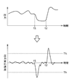
- FIG. 6 is a diagram showing a chest displacement waveform and a respiration waveform for each respiration sensor 1. Incidentally, in the figure, for easy understanding of the drawing, only the respiratory waveforms of the sensors A to C are shown in the six respiratory sensors 1, and the respiratory waveforms of the sensors D to F are omitted.
- the reflection sensor (strictly, the respiration sensor 1 corresponding to the reflection sensor) when the position of the center of gravity of the seated person is experimentally clarified, the result shown in FIG. can get.
- FIG. 7 is a diagram that experimentally clarifies the reflection sensor when the coordinates of the center of gravity position change. Each plot in the figure shows the center of gravity position, and the symbol displayed beside each plot is The respiration sensor 1 corresponding to the reflection sensor is shown.
- the seating surface Sf is divided into a plurality of areas (six areas in FIG. 5) as shown in FIG. 5 by dividing the area based on the experimental results shown in FIG.
- data indicating the correspondence between each area and the respiration sensor serving as the reflection sensor when the coordinates of the center of gravity position are present in the area that is, selection data is generated and stored in the storage unit 21.
- data indicating the correspondence shown in FIG. 8 is stored as selection data.
- FIG. 8 is a diagram showing a correspondence relationship between each area and the reflection sensor. Specifically, the coordinates (X coordinate and Y coordinate) indicating the range of each area and the coordinates of the center of gravity position in the area are shown. A respiration sensor 1 corresponding to a reflection sensor at a certain time is shown. Note that Xs and Ys in the figure are coordinate values for defining the boundary line of the area, and are specified from the experimental results shown in FIG. 7, for example.
- the area division of the seating surface Sf according to the present embodiment will be described in more detail with reference to FIG. 8.
- the seating surface Sf is partitioned so that two or more areas exist in both the width direction and the front-rear direction. .
- the selection data stored in the storage unit 21 is within the area for each area when the seating surface Sf is partitioned so that there are two or more areas in the width direction and the front-rear direction.
- the correspondence relationship defined by associating the respiration sensor 1 serving as a reflection sensor is shown.
- the seating surface Sf is partitioned so that the number of areas located on the rear side in the front-rear direction is larger than the number of areas located on the front side.
- the selection data stored in the storage unit 21 is within the area for each area when the area is divided so that the number of areas located on the rear side is larger than the number of areas located on the front side.
- the seating surface Sf is partitioned so that the areas exist symmetrically across the center position of the seating surface Sf in the width direction.
- the selection data stored in the storage unit 21 corresponds to each area when the seating surface Sf is partitioned so that the areas are symmetrically located across the center position of the seating surface Sf in the width direction.
- four areas are symmetrically arranged on the rear side of the seating surface Sf (specifically, the rear end) with the Y axis interposed therebetween.
- the more front area the area positioned in front of the rear end portion
- two areas are symmetrically arranged with the Y axis interposed therebetween.
- the seating surface Sf is centered on an area closer to the center position of the seating surface Sf (for example, area B and area E in FIG. 5) among the four areas arranged in the width direction on the rear side. It is partitioned so as to be narrower than an area farther from the position (for example, area A and area F in FIG. 5).
- the selection data stored in the storage unit 21 is such that the width of the area in the vicinity of the center position of the seating surface Sf (the length in the width direction) is shorter than the width of the area located on the outer side.
- the correspondence relationship defined by associating the respiration sensor 1 serving as a reflection sensor with the coordinates of the center of gravity in the area is shown for each area when the area is partitioned.
- the area specifying unit 22, the sensor selecting unit 23, the determining unit 24, and the change degree specifying unit 25 will be described.
- These functional units are configured by the controller 3, more specifically, a signal processor, an A / D converter and an arithmetic device mounted on the controller 3, and an arithmetic program executed by the arithmetic device.
- the area specifying unit 22 calculates the coordinates of the center of gravity position of the seated person in the XY coordinate space. More specifically, in the present embodiment, the area specifying unit 22 measures the measurement results of the sensors (strictly, the sensors B to E) that are arranged at positions sandwiching the Y axis among the six respiration sensors 1. Based on the above, the coordinates of the center of gravity position are calculated. More specifically, the measurement result of the B sensor is Pb, the measurement result of the C sensor is Pc, the measurement result of the D sensor is Pd, and the measurement result of the E sensor is Pe.
- the X coordinate Gx and the Y coordinate Gy are calculated by the following equations.
- Gx ⁇ m ⁇ (Pb + Pc) + ( ⁇ m) ⁇ (Pd + Pe) ⁇ / (Pb + Pc + Pd + Pe)
- Gy ⁇ n ⁇ (Pc + Pd) ⁇ / (Pb + Pc + Pd + Pe)
- the area specifying unit 22 specifies which area has the coordinates of the center of gravity among the six areas obtained by dividing the seating surface Sf as described above.
- the sensor selection unit 23 is a sensor corresponding to the area identified by the area identification unit 22 among the six respiratory sensors 1 based on the correspondence relationship indicated by the selection data stored in the storage unit 21, that is, the center of gravity. Select a sensor corresponding to the area to which the position belongs.
- the determination unit 24 determines the arousal state of the seated person based on the measurement result of only the sensor selected by the sensor selection unit 23.
- the change degree specifying unit 25 specifies the change degree of the measurement result of the respiration sensor 1 selected by the sensor selection unit 23.
- the degree of change is the amount of change per unit time of the sitting pressure measured by the respiration sensor 1 selected by the sensor selection unit 23. Specifically, it is a velocity component (hereinafter referred to as pressure change rate) obtained by first-order differentiation of a respiratory waveform indicating a change with time of sitting pressure.
- pressure change rate a velocity component obtained by first-order differentiation of a respiratory waveform indicating a change with time of sitting pressure.
- FIG. 9 is a diagram showing the measurement result of the respiration sensor 1 and the degree of change thereof.
- the upper figure in the figure shows a waveform (respiration waveform) showing the measurement result, and the lower figure in the figure shows the degree of change.
- the waveform of (pressure change speed) is shown.
- the change degree specifying unit 25 determines whether or not the magnitude of the specified change degree (pressure change speed) exceeds a threshold value. If it demonstrates in detail, referring FIG. 9, the change degree specific
- the change degree specifying unit 25 determines whether or not the magnitude of the pressure change rate exceeds a threshold value (Th in FIG. 9). In the case illustrated in FIG. 9, the magnitude of the pressure change rate exceeds the threshold Th with the movement of the seated person at the times t1 and t2, so the change degree specifying unit 25 determines that the magnitude of the pressure change rate is the threshold Th. Is determined to have exceeded
- a speed component obtained by first-order differentiation of the respiration waveform obtained from the measurement result. It is not limited to this.
- an acceleration component pressure change acceleration obtained by further differentiating the waveform of the pressure change speed may be used.
- the seating surface Sf of the vehicle seat S is divided into six areas as described above.
- each of the six areas is associated with a respiration sensor 1 that is a reflection sensor when the coordinates of the center of gravity position are in the area.
- data indicating the correspondence between each area and the respiration sensor 1, that is, selection data is generated and stored in the memory 4 of the ECU 2.
- the state determination flow is started when the seated person is seated on the vehicle seat S.
- each of the six respiration sensors 1 starts measurement, and the controller 3 acquires a measurement result from each respiration sensor 1 (S001).
- the controller 3 acquires only the measurement results of four respiration sensors 1 (specifically, sensors B to E) out of the six respiration sensors 1. Further, the controller 3 obtains measurement results for a predetermined time (for example, 30 seconds) for each of the four respiratory sensors 1, and then calculates an average value of the measurement results for the predetermined time.
- a predetermined time for example, 30 seconds
- the controller 3 calculates the coordinates of the center of gravity position of the seated person using the measurement results (strictly speaking, the average value in a predetermined time) of the four respiratory sensors 1 acquired in the previous step S001 (S002). . Based on the calculation result, the controller 3 specifies in which area the coordinates of the center of gravity position are located (S003, S004, S007, S008, S011). Thereafter, the controller 3 reads the selection data stored in the storage unit 21 and selects the respiration sensor 1 corresponding to the area to which the center of gravity position belongs from the correspondence relationship indicated by the data (S005, S006, S009, S010). , S012, S013).
- the controller 3 determines the arousal state of the seated person based on the measurement result of one sensor selected from the six respiration sensors 1.
- the sensor selection is performed again, and the respiration sensor 1 used for the state determination is selected again.
- the measurement result of the selected respiration sensor 1 is acquired at regular intervals (S014).
- the controller 3 (specifically, the change degree specifying unit 25) specifies the change degree of the measurement result of the respiration sensor 1, that is, the pressure change speed (S015). If the specified pressure change rate does not exceed the threshold Th (No in S016), the controller 3 is seated based on the measurement result of the respiration sensor 1 selected before the pressure change rate is specified. The person's awakening state is determined (S017).
- the process returns to Step S001, and the above-described series of processes is performed again from the beginning. That is, the controller 3 re-specifies in which area the coordinates of the center of gravity position of the seated person are located, and accordingly re-selects the respiration sensor 1 corresponding to the identified area. Thereafter, the controller 3 determines the awakening state of the seated person based on the measurement result of the reselected respiration sensor 1 (S017).
- one sensor is selected from the six respiration sensors 1 for the purpose of reducing the processing load related to the state determination. did.
- an appropriate respiration sensor 1 for determining the arousal state in consideration of the sitting position of the seated person to be used, and strictly speaking, a respiration sensor 1 corresponding to a reflection sensor is selected.
- a state determination flow when only one respiration sensor 1 is selected as a sensor that is actually used in the determination of the arousal state among the six respiration sensors 1, it can be selected easily and appropriately. It becomes.
- the awakening state of the seated person is determined based on the measurement result of one breath sensor 1 out of the six breath sensors 1, but the present invention is not limited to this. Absent. That is, a configuration example (hereinafter referred to as a modified example) in which the arousal state is determined based on the measurement results of the two respiratory sensors 1 out of the six respiratory sensors 1 is also conceivable.
- a state determination system according to a modification will be described.
- contents different from the state determination system according to the above-described embodiment that is, the present system 10
- description of contents common to the present system 10 will be omitted.
- each area when the seating surface Sf is divided into six areas is associated with the respiration sensor 1 serving as a reflection sensor when the coordinates of the center of gravity position are in the area, and the reflection sensor and A pair of respiration sensors 1 are associated together. That is, in the modified example, two respiration sensors 1 are associated with each area.
- the selection data stored in the storage unit 21 in the modified example shows the correspondence defined by associating the two respiration sensors 1 with each area.
- the respiration sensor 1 paired with the reflection sensor is a sensor having the highest correlation between its own measurement result and the measurement result of the reflection sensor among the five respiration sensors 1 excluding the reflection sensor. It is. Specifically, it is the respiration sensor 1 that makes a pair with the respiration sensor 1 corresponding to the reflection sensor among the two respiration sensors 1 corresponding to each area shown in FIG.
- FIG. 12 is a diagram showing a correspondence relationship between each area and the respiration sensor 1 in the modified example.
- the sensor E corresponds to a pair of sensors.
- the B sensor corresponds to the reflection sensor
- the E sensor corresponds to the paired sensor.
- the C sensor corresponds to the reflection sensor
- the D sensor corresponds to the paired sensor.
- the D sensor corresponds to the reflection sensor
- the C sensor corresponds to the paired sensor.
- the E sensor corresponds to the reflection sensor
- the A sensor corresponds to the paired sensor
- the F sensor corresponds to the reflection sensor
- the A sensor corresponds to the paired sensor.
- the selection data stored in the storage unit 21 in the modified example includes the coordinates of the sensor arrangement position when the coordinates of the center of gravity are located in the area among the six respiration sensors 1 for each area.
- the correspondence relationship defined by associating the two respiration sensors 1 straddling the coordinates of the center of gravity position in the direction is shown.
- FIG. 13 is a diagram showing a flow of a state determination flow according to the modification, and corresponds to FIG.
- FIG. 13 is a diagram showing a flow of a state determination flow according to the modification, and corresponds to FIG.
- the controller 3 acquires measurement results from the four respiration sensors 1 (strictly, sensors B to E). (S021). Further, the controller 3 calculates the coordinates of the center of gravity position of the seated person based on the measurement result of the respiratory sensor 1 acquired in the previous step S021 (S022).
- the controller 3 specifies which area the coordinates of the center of gravity position are located (S023, S024, S027, S028, S031). Thereafter, the controller 3 reads the selection data stored in the storage unit 21, and selects two respiration sensors 1 corresponding to the area to which the center of gravity position belongs from the correspondence relationship indicated by the data (S025, S026, S029). , S030, S032, S033).
- the controller 3 determines the awakening state of the seated person based on the measurement results of the two respiratory sensors 1 selected from the six respiratory sensors 1. Strictly speaking, the controller 3 according to the modification averages the measurement results of the two selected respiration sensors 1, and determines the arousal state based on the average value.
- the state determination flow As described above, in the state determination flow according to the modified example, two sensors are selected from the six respiration sensors 1, and the awakened state of the seated person is determined based on the two sensors. It was decided to. According to such a state determination flow, even if an abnormality occurs in one of the two selected respiration sensors 1, if the other sensor is normal, it is appropriate based on the measurement result of the sensor. It is possible to determine the awakening state of the seated person.
- the vehicle seat S is given as an example of the seating seat, but the seat is not limited to this.
- the present invention can also be applied to the determination of the physiological state of a seated person sitting on a general seating seat (seat) used in, for example, an entertainment facility such as a company, a school, a factory, a movie theater, a hospital, and a house. It is.
- the present invention can also be applied to a case where the physiological state of a seated person sitting on a seat seat mounted on a vehicle other than a vehicle is determined.
- respiration sensors 1 are provided in the rear part of the seat cushion S1, and two respiration sensors 1 are provided in the front region, respectively, in the width direction of the seating surface Sf. It is assumed that they are arranged symmetrically across the center position.
- the number and arrangement position of the respiration sensors 1 are not limited to the above contents.
- the number of the respiration sensors 1 arranged in the rear region is increased, and the respiration sensors 1 are arranged symmetrically with respect to the center position in the width direction of the seating surface Sf. For example, it is possible to select an appropriate respiration sensor 1 as a sensor corresponding to the area to which the center of gravity belongs.
- the seating surface Sf is divided into areas as shown in FIG. Specifically, the areas are divided so that two or more areas exist in each of the width direction and the front-rear direction. However, the present invention is not limited to this, and the areas may be divided so that there are two or more areas in at least one of the width direction and the front-rear direction. If the area is divided as in the above embodiment, the seating surface Sf is more finely divided, and the area to which the center of gravity belongs can be specified finely. As a result, a more appropriate sensor can be selected when selecting the respiration sensor 1 corresponding to the area to which the center of gravity belongs.
- the areas are divided so that the number of areas located on the rear side in the front-rear direction is larger than the number of areas located on the front side.
- the present invention is not limited to this, and the number of areas located on the front side may be larger than or equal to the number of areas located on the rear side.
- the area is divided as in the above embodiment, the number of areas in the rear area of the seating surface Sf where the center of gravity of the seated person is easily located is increased, so that the area to which the position of the center of gravity belongs is specified more precisely. Is possible. As a result, when selecting a sensor corresponding to the area to which the center of gravity belongs, a more appropriate sensor can be selected.
- the areas are divided so that the areas exist symmetrically with respect to the center position in the width direction of the seating surface Sf.
- the present invention is not limited to this, and the arrangement positions of the areas may be asymmetric in the width direction. If the areas are divided as in the above embodiment, it is possible to more easily identify the area to which the center of gravity belongs and select the sensor by using the symmetry of the area arrangement.
- the width of the area in the vicinity of the center position in the width direction of the seating surface Sf among the plurality of areas (specifically, four areas) arranged in a row in the width direction is the center position in the width direction.
- the area was divided so as to be shorter than the width of the area away from.
- the present invention is not limited to this, and the width of the area near the center in the width direction may be longer than the width of the area away from the center in the width direction. If the areas are divided as in the above embodiment, the area closer to the center position in the width direction of the seating surface Sf is narrower among the areas arranged in the width direction, so that the center of gravity position is near the center position in the width direction. It becomes possible to specify the area to which it belongs more finely. As a result, it is possible to select a more appropriate sensor when selecting a sensor corresponding to the area to which the center of gravity belongs.
Abstract
複数のセンサの一部の計測結果に基づいて着座者の生理的状態を判定するにあたり、一部のセンサを簡単且つ適切に選定する。 着座シートの着座面において変化する計測対象値を計測するセンサが、着座シートの幅方向及び前後方向を座標軸方向としたときのセンサ配置位置の座標が互いに異なるように、複数配置されている。また、着座面を複数のエリアに区画したときの各々のエリアに対して複数のセンサの一部を対応付けることで規定される対応関係を記憶する記憶部と、上記双方を座標軸の軸方向としたときに定められる着座者の重心位置の座標が、複数のエリアのうち、どのエリア内にあるのかを特定するエリア特定部と、記憶部が記憶した対応関係から、複数のセンサのうち、エリア特定部が特定したエリアと対応した一部のセンサを選定するセンサ選定部と、選定した一部のセンサの計測結果に基づいて着座者の生理的状態を判定する判定部と、が設けられている。
Description
本発明は、着座シートの着座者の生理的状態を判定する状態判定システムに係り、特に、着座者の生理的活動に応じて変化する計測対象値を計測するセンサが複数設けられた状態判定システムに関する。
着座シートの着座面において着座者の生理的活動に応じて変化する計測対象値を計測し、その計測結果に基づいて着座者の生理的状態を判定する状態判定システムは、既に知られている。状態判定システムの一例を挙げると、車両用シートの着座面に掛かる圧力を計測する圧力センサにて着座者の呼吸(具体的には、呼吸に伴う体表面の振動)を検出し、その検出結果に基づいて着座者の覚醒状態を判定するシステムが知られている。
また、状態判定システムの中には、上記の計測対象値を計測するセンサを複数箇所に設けているものが存在する。このように複数のセンサが設けられている構成では、例えば、それぞれのセンサの計測結果を集計して平均値等の代表値を求め、当該代表値に基づいて状態判定を行うことになる。ただし、複数のセンサすべての計測結果を集計することになるため、その分、処理負荷が大きくなってしまう。また、複数のセンサの各々の配置位置が互いに異なるので、各センサの計測結果は、着座面において着座者が実際に座る位置や着座者の姿勢に応じて変動することになる。
以上の事情から、複数のセンサが設けられた状態判定システムにおいて、複数のセンサの中から適当なセンサを選定し、選定したセンサのみの集計結果に基づいて状態判定を行うことが考えられる。具体例を挙げて説明すると、特許文献1に記載の状態判定システム(特許文献1では「覚醒度推定装置」)では、複数のセンサの中から、着座者に安定して接触していると判定されるセンサを特定し、特定したセンサのみの計測結果に基づいて状態判定を行う。別の例を挙げると、特許文献2に記載の状態判定システム(特許文献2では「生体情報取得装置」)では、複数のセンサのそれぞれに対して、着座者の心拍を正確に検出しているかどうかの評価値を算出し、評価値が最も高いセンサのみの計測結果に基づいて状態判定を行う。
ところで、複数のセンサが設けられた状態判定システムにおいて、複数のセンサの中から一部のセンサを選定して当該一部のセンサの計測結果に基づいて状態判定を行う場合には、簡単且つ適切にセンサを選定するのが望ましい。しかしながら、特許文献1では、選定されるセンサ(厳密には、着座者に安定して接触していると判定されるセンサ)について、具体的な特定方法が記載されていない。また、特許文献2では、センサを選定するにあたり、複数のセンサのそれぞれに対して評価値を算出するために演算処理等の処理負荷が高くなる。
一方、前述したように、複数のセンサの各々がその配置箇所にて計測対象値を計測した際の計測結果は、着座面において着座者が実際に座る位置(以下、座位置)や着座者の姿勢に応じて変動する。また、着座者が身動き等して上記の座位置や姿勢自体が変化する場合があり、かかる場合において複数のセンサの中から一部のセンサを選定する際には、変化後の座位置や姿勢を考慮してセンサを改めて選定する必要がある。
そこで、本発明は、上記の問題に鑑みてなされたものであり、その目的は、複数のセンサの中から一部のセンサを選定し当該一部のセンサの計測結果に基づいて着座者の生理的状態を判定する状態判定システムとして、簡単且つ適切にセンサを選定することが可能なシステムを提供することにある。
また、本発明の他の目的は、着座者が身動き等して着座状態が変化した場合において変化後の着座状態を考慮してセンサを選定することである。
また、本発明の他の目的は、着座者が身動き等して着座状態が変化した場合において変化後の着座状態を考慮してセンサを選定することである。
前記課題は、本発明の状態判定システムによれば、着座シートの着座面において着座者の生理的活動に応じて変化する計測対象値を計測するセンサと、該センサの計測結果に基づいて前記着座者の生理的状態を判定する判定装置と、を有し、前記センサは、前記着座シートの幅方向及び前後方向の双方を座標軸の軸方向としたときに定められる前記センサの配置位置の座標が互いに異なるように、複数配置されており、前記判定装置は、前記着座面を複数のエリアに区画したときの各々の前記エリアに対して複数の前記センサの一部を対応付けることで規定される対応関係を記憶する記憶部と、前記双方を座標軸の軸方向としたときに定められる前記着座者の重心位置の座標が、複数の前記エリアのうち、どのエリア内にあるのかを特定するエリア特定部と、前記記憶部が記憶した前記対応関係から、複数の前記センサのうち、前記エリア特定部が特定した前記エリアと対応した一部の前記センサを選定するセンサ選定部と、該センサ選定部が選定した一部の前記センサの計測結果に基づいて前記生理的状態を判定する判定部と、を有することにより解決される。
以上のように構成された本発明の状態判定システムでは、着座面を複数のエリアに区画し、複数のエリアの各々に対して、複数のセンサのうちの一部が対応付けられている。その上で、着座者の重心位置の座標が複数のエリアのうち、どのエリア内にあるのかを特定し、特定したエリアと対応したセンサを選定する。そして、選定された一部のセンサのみの計測結果に基づいて着座者の生理的状態を判定する。このように本発明の状態判定システムでは、着座者の着座状態を示す指標として重心位置を用い、この重心位置に基づいてセンサを選定するため、着座者の着座状態を考慮して適当と考えられるセンサを選定することが可能となる。また、センサを選定する際には、重心位置が属するエリアを特定した上で、エリアとセンサとの対応関係を記憶部から読み出し当該対応関係を参照することで、重心位置が属するエリアと対応したセンサを選定することになる。これにより、複数のセンサの中から適当なセンサを容易に選定することが可能となる。
また、上記の状態判定システムにおいて、前記記憶部は、前記双方のそれぞれにおいて2つ以上の前記エリアが存在するように前記着座面を区画したときの各々の前記エリアに対して複数の前記センサの一部を対応付けることで規定される前記対応関係を記憶していると、好適である。
上記の構成によれば、着座シートの前後方向及び幅方向のそれぞれにおいて2つ以上のエリアが存在するように着座面を区画し、各エリアに対して複数のセンサの一部を対応付けている。これにより、着座面がより細かく区画されるので、重心位置が属するエリアを細かに特定することが可能となる。この結果、重心位置が属するエリアと対応したセンサを選定する際にも、より適切にセンサを選定することが可能となる。
上記の構成によれば、着座シートの前後方向及び幅方向のそれぞれにおいて2つ以上のエリアが存在するように着座面を区画し、各エリアに対して複数のセンサの一部を対応付けている。これにより、着座面がより細かく区画されるので、重心位置が属するエリアを細かに特定することが可能となる。この結果、重心位置が属するエリアと対応したセンサを選定する際にも、より適切にセンサを選定することが可能となる。
また、上記の状態判定システムにおいて、前記記憶部は、前記前後方向において後側に位置する前記エリアの数が前側に位置する前記エリアの数よりも多くなるように前記着座面を区画したときの各々の前記エリアに対して複数の前記センサの一部を対応付けることで規定される前記対応関係を記憶していると、より好適である。
上記の構成では、前後方向において後側に位置するエリアの数が前側に位置するエリアの数よりも多くなるように着座面を区画する。これは、一般に着座者の重心が着座面の後側に位置し易いことを反映している。このように後側でエリア数をより多くすれば、重心位置が属するエリアをより細かに特定することが可能となる結果、重心位置が属するエリアと対応したセンサを選定する際には、より適切にセンサを選定することが可能となる。
上記の構成では、前後方向において後側に位置するエリアの数が前側に位置するエリアの数よりも多くなるように着座面を区画する。これは、一般に着座者の重心が着座面の後側に位置し易いことを反映している。このように後側でエリア数をより多くすれば、重心位置が属するエリアをより細かに特定することが可能となる結果、重心位置が属するエリアと対応したセンサを選定する際には、より適切にセンサを選定することが可能となる。
また、上記の状態判定システムにおいて、前記センサは、少なくとも3個以上配置されており、前記記憶部は、各々の前記エリアに対して2個の前記センサを対応付けることで規定される前記対応関係を記憶していると、尚好適である。
上記の構成では、各エリアに対して2個のセンサが対応付けられている。つまり、状態判定時に採用されるセンサの計測結果としては、2個のセンサの計測結果となる。このような構成では、仮に2個のセンサのうちの一方に異常が生じたとしても、他方のセンサが正常であれば、当該センサの計測結果に基づいて適切に着座者の生理的状態を判定することが可能となる。
上記の構成では、各エリアに対して2個のセンサが対応付けられている。つまり、状態判定時に採用されるセンサの計測結果としては、2個のセンサの計測結果となる。このような構成では、仮に2個のセンサのうちの一方に異常が生じたとしても、他方のセンサが正常であれば、当該センサの計測結果に基づいて適切に着座者の生理的状態を判定することが可能となる。
また、上記の状態判定システムにおいて、前記記憶部は、各々の前記エリアに対して、複数の前記センサのうち、各々の前記エリア内に前記重心位置の座標があるときに前記配置位置の座標が前記幅方向において前記重心位置の座標を跨いでいる2個の前記センサを対応付けることで規定される前記対応関係を記憶していると、更に好適である。
上記の構成では、各エリアに重心位置の座標があるとき、当該重心位置の座標を跨ぐ位置に配置された2個のセンサを選定することになっている。一般に、複数のセンサのうち、重心位置を跨ぐ位置に配置された2個のセンサ同士については、その計測結果が互いに相関を示す傾向にある。このため、重心位置の座標を跨ぐ位置に配置された2個のセンサのそれぞれの計測結果を用いれば、より適切に着座者の生理的状態を判定することが可能となる。
上記の構成では、各エリアに重心位置の座標があるとき、当該重心位置の座標を跨ぐ位置に配置された2個のセンサを選定することになっている。一般に、複数のセンサのうち、重心位置を跨ぐ位置に配置された2個のセンサ同士については、その計測結果が互いに相関を示す傾向にある。このため、重心位置の座標を跨ぐ位置に配置された2個のセンサのそれぞれの計測結果を用いれば、より適切に着座者の生理的状態を判定することが可能となる。
また、上記の状態判定システムにおいて、前記記憶部は、前記幅方向において前記着座面の中央位置を挟んで前記エリアが対称的に存在するように前記着座面を区画したときの各々の前記エリアに対して複数の前記センサの一部を対応付けることで規定される前記対応関係を記憶していると、尚一層好適である。
上記の構成では、着座シートの幅方向において着座面の中央位置を挟んで対称的にエリアが存在するように着座面を区画し、各エリアに対して複数のセンサのうちの一部を対応付けている。かかる構成によれば、エリア配置の対称性を利用して、重心位置が属するエリアの特定や当該エリアと対応したセンサの選定をより容易に行うことが可能となる。
上記の構成では、着座シートの幅方向において着座面の中央位置を挟んで対称的にエリアが存在するように着座面を区画し、各エリアに対して複数のセンサのうちの一部を対応付けている。かかる構成によれば、エリア配置の対称性を利用して、重心位置が属するエリアの特定や当該エリアと対応したセンサの選定をより容易に行うことが可能となる。
また、上記の状態判定システムにおいて、前記記憶部は、前記幅方向に並ぶ少なくとも3つ以上の前記エリアのうち、前記着座面の中央位置により近い前記エリアの前記幅方向における長さが前記中央位置からより離れた前記エリアの前記長さよりも短くなるように前記着座面を区画したときの各々の前記エリアに対して複数の前記センサの一部を対応付けることで規定される前記対応関係を記憶していると、益々好適である。
上記の構成では、着座シートの幅方向に並ぶ少なくとも3つ以上のエリアのうち、着座面の中央位置により近いエリアが、当該中央位置からより離れたエリアに比べて幅狭となるように着座面を区画し、各エリアに対して複数のセンサのうちの一部を対応付けている。このように幅方向に並ぶ各エリアのうち、着座面の中央位置に近いエリアほど幅狭とすることにより、中央位置付近において重心位置が属するエリアをより細やかに特定することが可能となる。この結果、重心位置が属するエリアと対応したセンサを選定する際、より適切なセンサを選定することが可能となる。
上記の構成では、着座シートの幅方向に並ぶ少なくとも3つ以上のエリアのうち、着座面の中央位置により近いエリアが、当該中央位置からより離れたエリアに比べて幅狭となるように着座面を区画し、各エリアに対して複数のセンサのうちの一部を対応付けている。このように幅方向に並ぶ各エリアのうち、着座面の中央位置に近いエリアほど幅狭とすることにより、中央位置付近において重心位置が属するエリアをより細やかに特定することが可能となる。この結果、重心位置が属するエリアと対応したセンサを選定する際、より適切なセンサを選定することが可能となる。
また、上記の状態判定システムにおいて、前記前後方向において後側に配置された前記センサの数は、前側に配置された前記センサの数よりも多いと、一段と好適である。
上記の構成では、着座シートの前後方向において後側に配置されたセンサの数が前側に配置されたセンサの数よりも多くなっている。これは、一般に着座者の重心が着座面の後側に位置し易いことを反映している。このように後側でセンサの配置数をより多くすれば、重心位置が属するエリアに対応したセンサとして、より適切なセンサを選定することが可能となる。
上記の構成では、着座シートの前後方向において後側に配置されたセンサの数が前側に配置されたセンサの数よりも多くなっている。これは、一般に着座者の重心が着座面の後側に位置し易いことを反映している。このように後側でセンサの配置数をより多くすれば、重心位置が属するエリアに対応したセンサとして、より適切なセンサを選定することが可能となる。
また、上記の状態判定システムにおいて、前記前後方向において後側には4個の前記センサが、前記幅方向において前記着座面の中央位置を挟んで対称的に配置され、前側には2個の前記センサが、前記幅方向において前記中央位置を挟んで対称的に配置されていると、更に好適である。
上記の構成では、着座シートの前後方向において後側には4個のセンサが、前側には2個のセンサが、それぞれ着座面の幅方向中央位置を挟んで対称的に配置されている。このように着座面の後側においてセンサの配置数をより多くし、且つ、各センサが着座面の幅方向中央位置を挟んで対称的に配置されていれば、重心位置が属するエリアと対応したセンサとして、より適切なセンサを選定することが可能となる。
上記の構成では、着座シートの前後方向において後側には4個のセンサが、前側には2個のセンサが、それぞれ着座面の幅方向中央位置を挟んで対称的に配置されている。このように着座面の後側においてセンサの配置数をより多くし、且つ、各センサが着座面の幅方向中央位置を挟んで対称的に配置されていれば、重心位置が属するエリアと対応したセンサとして、より適切なセンサを選定することが可能となる。
また、上記の状態判定システムにおいて、前記記憶部は、各々の前記エリアに対して、複数の前記センサのうち、各々の前記エリア内に前記重心位置の座標があるときに前記生理的活動の前記計測対象値の計測結果への反映度がより高くなる前記センサを対応付けることで規定される前記対応関係を記憶していると、好適である。
上記の構成では、各エリアに対して、当該各エリア内に重心位置の座標があるときに生理的活動の計測対象値の計測結果への反映度がより高くなるセンサが対応付けられている。これにより、重心位置が属するエリアと対応したセンサを上記の対応関係に基づいて選定する際に、適切なセンサを選定することが可能となる。
上記の構成では、各エリアに対して、当該各エリア内に重心位置の座標があるときに生理的活動の計測対象値の計測結果への反映度がより高くなるセンサが対応付けられている。これにより、重心位置が属するエリアと対応したセンサを上記の対応関係に基づいて選定する際に、適切なセンサを選定することが可能となる。
また、上記の状態判定システムにおいて、前記判定装置は、前記センサ選定部が選定した一部の前記センサの計測結果の変化度合いを特定する変化度合い特定部を更に有し、該変化度合い特定部が特定した前記変化度合いの大きさが閾値を超えたとき、前記エリア特定部が前記エリアを特定し直すのに伴って前記センサ選定部が一部の前記センサを選定し直し、選定し直した一部の前記センサのみの計測結果に基づいて前記判定部が前記生理的状態を判定し、前記変化度合い特定部が特定した前記変化度合いの大きさが前記閾値を下回るとき、前記判定部は、前記変化度合い特定部が前記変化度合いを特定する前の時点で前記センサ選定部が選定した一部の前記センサのみの計測結果に基づいて前記生理的状態を判定すると、好適である。
上記の構成では、センサ選定部が選定したセンサの計測結果が著しく変化した場合、センサの選定を行い、選定し直したセンサの計測結果に基づいて状態判定を行う。このような構成であれば、着座者が動いて重心位置が変わったとしても、センサを選定し直すことにより、変化後の重心位置が属するエリアと対応したセンサを選定することが可能となる。
一方、センサ選定部が選定したセンサの計測結果に顕著な変化が見られない場合、それまで使用してきたセンサの計測結果を引き続き利用し、当該計測結果に基づいて状態判定を行う。つまり、重心位置が変化していない間は、同じセンサの計測結果を用い続けることとし、以て、センサの再選定を行う手間が省略可能となる。
本発明によれば、複数のセンサ中、一部のセンサの計測結果に基づいて着座者の生理的状態を判定するにあたり、当該一部のセンサを簡単且つ適切に選定することが可能となる。
また、本発明によれば、着座シートの前後方向及び幅方向のそれぞれにおいて2つ以上のエリアが存在するように着座面を区画することで、重心位置が属するエリアを細かに特定することが可能となる結果、より適切にセンサを選定することが可能となる。
また、本発明によれば、後側に位置するエリアの数が前側に位置するエリアの数よりも多くなるように着座面を区画することで、重心位置が属するエリアをより細かに特定し、より適切なセンサを選定することが可能となる。
また、本発明によれば、各エリアに対して2個のセンサが対応付けられていることで、仮に2個のセンサのうちの一方に異常が生じたときでも、着座者の生理的状態を適切に判定することが可能となる。
また、本発明によれば、各エリアに重心位置の座標があるとき、当該重心位置の座標を跨ぐ位置に配置された2個のセンサを選定することで、着座者の生理的状態をより適切に判定することが可能となる。
また、本発明によれば、着座シートの幅方向において着座面の中央位置を挟んで対称的にエリアが存在するように着座面を区画することで、エリア配置の対称性を利用して、重心位置が属するエリアの特定やセンサの選定をより容易に行うことが可能となる。
また、本発明によれば、幅方向に並ぶ各エリアのうち、着座面の中央位置に近いエリアほど幅狭とすることで、中央位置付近において重心位置が属するエリアをより細やかに特定し、より適切なセンサを選定することが可能となる。
また、本発明によれば、後側に配置されたセンサの数が前側に配置されたセンサの数よりも多くなっていることで、より適切なセンサを選定することが可能となる。
また、本発明によれば、後側に4個のセンサが、前側に2個のセンサが、それぞれ着座面の幅方向中央位置を挟んで対称的に配置されていることにより、より適切なセンサを選定することが可能となる。
また、本発明によれば、各エリアに対して、当該各エリア内に重心位置の座標があるときに生理的活動の計測対象値の計測結果への反映度がより高くなるセンサが対応付けられているため、適切なセンサを選定することが可能となる。
また、本発明によれば、着座者が動いて重心位置が変わったとしても、センサを選定し直して、変化後の重心位置が属するエリアと対応したセンサを選定することが可能となる。一方で、重心位置が変化していない間は、同じセンサの計測結果を用い続けることにより、センサを再度選定する手間を省略することが可能となる。
<<本発明の一実施形態に係る状態判定システムについて>>
以下、本発明の一実施形態(本実施形態)に係る状態判定システムについて説明する。なお、以下では、車両に搭載された車両用シートを着座シートの一例として挙げて説明することとする。また、以下の説明において、「前後方向」とは、着座シートの前後方向に相当し、車両用シートに着座した着座者から見たときの前後方向、具体的には車両の前後方向(換言すると、走行方向)のことである。また、「幅方向」とは、着座シートの幅方向に相当し、車両用シートに着座した着座者から見たときの左右方向のことである。
以下、本発明の一実施形態(本実施形態)に係る状態判定システムについて説明する。なお、以下では、車両に搭載された車両用シートを着座シートの一例として挙げて説明することとする。また、以下の説明において、「前後方向」とは、着座シートの前後方向に相当し、車両用シートに着座した着座者から見たときの前後方向、具体的には車両の前後方向(換言すると、走行方向)のことである。また、「幅方向」とは、着座シートの幅方向に相当し、車両用シートに着座した着座者から見たときの左右方向のことである。
本実施形態に係る状態判定システム(以下、本システム10)は、車両用シートの着座者の生理的状態を判定(推定)するためのシステムである。なお、本実施形態において「生理的状態」とは、着座者の覚醒状態を意味するが、これに限定されるものではない。「生理的状態」は、覚醒状態のほか、着座者の精神安定状態や泥酔状態等、着座者の身体各部(臓器や神経を含む)の働きや機能の正常・異常に関する状態を意味し、このような状態を判定するシステムに対して本発明が適用可能である。
本システム10の構成について図1を参照しながら説明すると、本システム10は、センサとしての呼吸センサ1と、判定装置としてのECU(Electronic Control Unit)2によって構成されている。図1は、本システム10の全体構成を概念的に示した図である。
呼吸センサ1は、公知の圧力センサからなり、例えば、ピエゾセンサ式の圧力センサ、半導体ピエゾ抵抗式の圧力センサ、歪みゲージ式の圧力センサ、静電容量式の圧力センサ、あるいはシリコンレゾナント式の圧力センサ等からなる。また、呼吸センサ1は、車両用シートSのシートクッションS1、より具体的には、シートクッションS1の着座部(着座者の臀部を支える部分)に備えられている。
そして、呼吸センサ1は、着座者が車両用シートSに着座した際にシートクッションS1の上面、すなわち着座面Sfに掛かる圧力(着座圧)を計測する。ここで、着座圧は、車両用シートSに着座した着座者の生理的活動、具体的には呼吸に応じて周期的に変化する。つまり、呼吸センサ1は、着座面Sfにおいて着座者の呼吸に応じて変化する着座圧を、計測対象値として計測する。なお、呼吸センサ1は、着座圧を計測する上で着座面Sfの直下位置に配置されており、厳密には、シートクッションS1を構成するクッションパッド及びクッションパッドを覆う表皮材との間に挟まれる位置に配置されている。ただし、これに限定されるものではなく、適切に着座圧を計測し得る位置であればよく、例えば、シートクッションS1の着座面Sf上に呼吸センサ1が配置されてもよい。
また、本実施形態において、呼吸センサ1は、図1に示すように、シートクッションS1の後方部において互いに異なる位置に複数配置されており、具体的には6箇所に配置されている。各呼吸センサ1の配置位置については後に詳しく説明する。
なお、本実施形態では計測対象値として着座圧を計測することとしたが、これに限定されるものではない。すなわち、着座面Sfにおいて着座者の呼吸に応じて変化する物理量であれば計測対象値とすることが可能であり、例えば、着座面Sfの撓み具合や着座面Sfの温度を計測対象値としてもよい。
ECU2は、呼吸センサ1の計測結果に基づいて着座者の覚醒状態を判定する装置である。なお、呼吸センサ1の計測結果(すなわち、着座圧の計測結果)に基づいて着座者の覚醒状態を判定する方法としては、公知の判定方法が利用可能である。一例を挙げると、着座圧の周期的変化を示す波形において、その周期(換言すると、ピーク間の間隔)を求め、当該間隔の値が通常の範囲内にあるか否かによって着座者の覚醒状態を判定することとしてもよい。
ECU2のハードウェア構成について概説すると、コントローラ3とメモリ4とがECU2の主な構成要素として設けられている。コントローラ3は、不図示の信号処理器、A/Dコンバータ及び演算機器によって構成されている。コントローラ3は、呼吸センサ1から、その計測結果を示す信号を受信し、当該信号に対して信号処理及びA/D変換処理を実行した上で所定の演算処理を実行する。そして、コントローラ3は、状態判定用の演算処理を通じて、着座者の覚醒状態を判定する。
また、本実施形態に係るコントローラ3は、複数の呼吸センサ1のうち、一部の呼吸センサ1のみの計測結果に基づいて覚醒状態の判定を行う。これにより、本実施形態では、複数の呼吸センサ1すべての計測結果を用いて覚醒状態の判定を行う場合と比較して、演算処理の負荷が軽減され、且つ、より妥当な判定結果が得られるようになる。かかる効果は、本システム10によって実現される格別な効果である。以下、当該効果を実現するための構成について詳しく説明する。
上記効果を実現するための構成として、先ず、図2を参照しながらECU2の構成をその機能面から改めて説明することとする。図2は、ECU2の構成を機能面から示したブロック図である。ECU2は、状態判定に係る各種の機能部、具体的には図2に図示の記憶部21、エリア特定部22、センサ選定部23、判定部24及び変化度合い特定部25を有する。記憶部21は、ECU2のメモリ4からなり、複数の呼吸センサ1の中から状態判定時に実際に使用するセンサを選定するために必要なデータ(以下、センサ選定用データ)を記憶している。
センサ選定用データについて説明するにあたり、図3を参照しながら、各呼吸センサ1の配置位置について説明する。図3は、各呼吸センサ1の配置を示す平面図である。本実施形態において、複数の呼吸センサ1は、XY座標空間において各呼吸センサ1の配置位置の座標が互いに異なるように配置されている。ここで、XY座標空間とは、幅方向及び前後方向の双方を座標軸の軸方向としたときに定められる二次元座標空間のことである。なお、当該座標空間における原点位置の座標については、そのX座標が幅方向における着座面Sfの中央位置となっており、そのY座標が前後方向における着座面Sfの中央位置よりも幾分後ろ寄りの位置となっている。
複数の呼吸センサ1は、図3に示すように前後に分かれて配置されており、具体的には、より後側に4個の呼吸センサ1が、より前側に2個の呼吸センサ1が、それぞれ幅方向に沿って列状に並ぶように配置されている。また、複数の呼吸センサ1は、Y軸(換言すると、幅方向における着座面Sfの中央位置)を挟んで左右対称に配置されている。すなわち、シートクッションS1の後方部において、より後側の領域には4個の呼吸センサ1がY軸を挟んで対称的に配置されており、より前側の領域には2個の呼吸センサ1がY軸を挟んで対称的に配置されている。このように後側の領域でのセンサ配置数が前側の領域でのセンサ配置数よりも多くなっているのは、一般的に着座者の重心が着座面Sfにおいてより後側に位置し易いことを反映している。
なお、以下では、各呼吸センサ1を識別する上で6個の呼吸センサ1を、Aのセンサ、Bのセンサ、Cのセンサ、Dのセンサ、Eのセンサ、Fのセンサと呼ぶこととする。ちなみに、各呼吸センサ1の配置位置の座標は、下記の通りである。
(Aのセンサの配置位置)=(Xa,0) Xaは0より大きい任意の実数
(Bのセンサの配置位置)=(Xb,0) Xbは0より大きくXaよりも小さい実数
(Cのセンサの配置位置)=(Xb,Yc) Ycは0より大きい任意の実数
(Dのセンサの配置位置)=(-Xb,Yc)
(Eのセンサの配置位置)=(-Xb,0)
(Fのセンサの配置位置)=(-Xa,0)
(Aのセンサの配置位置)=(Xa,0) Xaは0より大きい任意の実数
(Bのセンサの配置位置)=(Xb,0) Xbは0より大きくXaよりも小さい実数
(Cのセンサの配置位置)=(Xb,Yc) Ycは0より大きい任意の実数
(Dのセンサの配置位置)=(-Xb,Yc)
(Eのセンサの配置位置)=(-Xb,0)
(Fのセンサの配置位置)=(-Xa,0)
ところで、上記の如く各呼吸センサ1の配置位置が異なるため、6個の呼吸センサ1のそれぞれが計測する着座圧についても異なってくる。具体的に説明すると、ある着座状態(厳密には、座位置や着座姿勢)にて着座者が車両用シートSに座った状態で各呼吸センサ1が着座圧を計測すると、図4に示すように、計測結果を示す波形(以下、呼吸波形)がセンサ毎に異なる。図4は、呼吸センサ1別の呼吸波形を示す図である。
各呼吸センサ1の呼吸波形は、上記の如くセンサ毎に異なり、また、着座者の着座状態に応じて変動する。一方で、状態判定時に実際使用する呼吸センサ1としては、6個の呼吸センサ1中、呼吸波形の波形パターンが着座者の呼吸動作をより反映しているセンサ(以下、反映センサ)を選定する必要がある。そこで、本実施形態では、着座状態が変化したときに6個の呼吸センサ1中、どのセンサが反映センサに該当するのかを明らかにし、その結果に基づいて着座面Sfをエリア分けしている。
より具体的に説明すると、本実施形態では、図5に示すように、着座面SfをXY座標空間において複数のエリアに区画している。図5は、着座面Sfを複数のエリアに区画したときの各エリアの位置を示す図である。また、各エリアには、呼吸センサ1が一つずつ対応している。より詳しく説明すると、各エリアには、図5中、各エリアに付された記号と同じ記号の呼吸センサ1が対応付けられており、例えば、エリアAにはAのセンサが対応付けられている。
各エリア及び当該各エリアと対応した呼吸センサ1の関係について説明すると、XY座標空間における着座者の重心位置の座標があるエリア内にあるとき、当該あるエリアと対応した呼吸センサ1は、その時点での反映センサとなる。つまり、図5に示した着座面Sf中の各エリアは、当該エリア内に着座者の重心位置の座標があるときにどの呼吸センサ1が反映センサとなるのかを示したもの(換言すると、反映センサとなる呼吸センサ1とその適用範囲)である。そして、各エリアの範囲と、当該エリア内に重心位置の座標があるときに反映センサとなる呼吸センサ1と、の対応関係を示すデータが生成され、センサ選定用データとして記憶部21に記憶されている。以下、上記の対応関係について詳しく説明する。
上記の対応関係は、着座面を複数のエリアに区画したときの各々のエリアに対して6個の呼吸センサ1の一部を対応付けることで規定されるものである。具体的に説明すると、各々のエリアに対して、当該エリア内に着座者の重心位置の座標があるときに反映センサとなる呼吸センサ1を対応付けることで規定される。ここで、反映センサの特定方法について説明すると、あるエリア内に着座者の重心位置があるときに、6個の呼吸センサ1のうち、「呼吸波形への呼吸動作の反映度」が最も高くなるセンサを反映センサとして特定する。「呼吸波形への呼吸動作の反映度」とは、呼吸動作が呼吸波形(着座圧の計測結果)に反映される際の度合いを意味する。
反応センサの特定方法についてより詳しく説明すると、あるエリア内に着座者の重心位置がある状態において、各呼吸センサ1にて着座圧を計測するとともに、着座者の呼吸動作に伴って顕著に変化する物理量、例えば着座者の胸部の変位量(つまり、胸部の膨らみ量)を別センサにて計測する。計測終了後、各呼吸センサ1の計測結果から得られる呼吸波形と、胸部の変位量の計測結果から得られる波形(以下、胸部変位波形)と、を対比する。ここで、両波形を対比すると、図6に示すように、呼吸センサ1別の呼吸波形の中で、波形パターンが胸部変位波形と最も近似する呼吸波形が特定される。かかる呼吸波形が、着座者の呼吸動作の反映度が最も高い呼吸波形に相当し、この呼吸波形を得た呼吸センサ1が反映センサに相当する。なお、図6は、胸部変位波形と呼吸センサ1別の呼吸波形とを示す図である。ちなみに、同図では、図示を分かり易くするため、6個の呼吸センサ1中、A~Cのセンサの呼吸波形のみを図示し、D~Fのセンサの呼吸波形を省略している。
以上の特定方法に則って、着座者の重心位置が変化したときの反映センサ(厳密には、反映センサに該当する呼吸センサ1)を実験的に明らかにすることで、図7に示す結果が得られる。図7は、重心位置の座標が変化した際の反映センサを実験的に明らかにした図であり、同図中の各プロットが重心位置を示しており、各プロットの脇に表示された記号が反映センサに該当する呼吸センサ1を示している。
そして、図7に図示した実験結果に基づいてエリア分けすることで、着座面Sfが図5に示すように複数のエリア(図5では6つのエリア)に区画される。その上で、各エリアと当該エリア内に重心位置の座標があるときに反映センサとなる呼吸センサとの対応関係を示すデータ、すなわち、選定用データが生成されて記憶部21に記憶される。そして、本実施形態では、図8に図示した対応関係を示すデータが選定用データとして記憶される。図8は、各エリアと反映センサとの対応関係を示した図であり、具体的には、各エリアの範囲を示す座標(X座標及びY座標)と、当該エリア内に重心位置の座標があるときに反映センサに該当する呼吸センサ1とが示されている。なお、図中のXs及びYsは、エリアの境界線を規定するための座標値であり、例えば図7に示す実験結果から特定される。
本実施形態に係る着座面Sfのエリア分けについて図8を参照しながらより詳しく説明すると、着座面Sfは、幅方向及び前後方向の双方においてそれぞれ2つ以上のエリアが存在するように区画される。換言すると、記憶部21が記憶する選定用データは、幅方向及び前後方向のそれぞれにおいて2つ以上のエリアが存在するように着座面Sfを区画したときの各エリアに対して、当該エリア内に重心位置の座標があるときに反映センサとなる呼吸センサ1を対応付けることで規定される対応関係を示すことになる。
また、本実施形態において、着座面Sfは、前後方向において後側に位置するエリアの数が前側に位置するエリアの数よりも多くなるように区画される。換言すると、記憶部21が記憶する選定用データは、後側に位置するエリアの数が前側に位置するエリアの数よりも多くなるように区画したときの各エリアに対して、当該エリア内に重心位置の座標があるときに反映センサとなる呼吸センサ1を対応付けることで規定される対応関係を示すことになる。なお、上述したように後側に位置するエリアの数を前側に位置するエリアの数よりも多くしているのは、一般に着座者の重心が着座面Sfの後側に位置し易いことを反映している。
さらに、本実施形態において、着座面Sfは、幅方向において着座面Sfの中央位置を挟んでエリアが対称的に存在するように区画されている。換言すると、記憶部21が記憶する選定用データは、幅方向において着座面Sfの中央位置を挟んでエリアが対称的に存在するように着座面Sfを区画したときの各エリアに対して、当該エリア内に重心位置の座標があるときに反映センサとなる呼吸センサ1を対応付けることで規定される対応関係を示すことになる。
なお、本実施形態では、図5に示すように、着座面Sfの後側の領域(具体的には、後端部)には4つのエリアがY軸を挟んで対称的に配置されており、より前側の領域(後端部よりも前方に位置する領域)には2つのエリアがY軸を挟んで対称的に配置されている。
さらにまた、本実施形態において、着座面Sfは、より後側で幅方向に並ぶ4つのエリアのうち、着座面Sfの中央位置により近いエリア(例えば図5中のエリアB、エリアE)が中央位置からより離れたエリア(例えば図5中のエリアA、エリアF)に比して幅狭となるように区画される。換言すると、記憶部21が記憶する選定用データは、着座面Sfの中央位置近傍のエリアの幅(幅方向における長さ)がより外側に位置するエリアの幅よりも短くなるように着座面Sfを区画したときの各エリアに対して、当該エリア内に重心位置の座標があるときに反映センサとなる呼吸センサ1を対応付けることで規定される対応関係を示すことになる。
次に、エリア特定部22、センサ選定部23、判定部24及び変化度合い特定部25について説明する。これらの機能部は、コントローラ3、より具体的には、コントローラ3に搭載された信号処理器、A/Dコンバータ及び演算機器、並びに演算機器が実行する演算プログラムによって構成されるものである。
エリア特定部22は、XY座標空間における着座者の重心位置の座標を算出する。具体的に説明すると、本実施形態において、エリア特定部22は、6個の呼吸センサ1のうち、Y軸を挟む位置に配置されたセンサ(厳密には、B~Eのセンサ)の計測結果に基づいて重心位置の座標を算出する。より詳しく説明すると、Bのセンサの計測結果をPbとし、Cのセンサの計測結果をPcとし、Dのセンサの計測結果をPdとし、Eのセンサの計測結果をPeとしたとき、重心位置のX座標Gx及びY座標Gyは、下記の式によって算出される。
Gx={m×(Pb+Pc)+(-m)×(Pd+Pe)}/(Pb+Pc+Pd+Pe)
Gy={n×(Pc+Pd)}/(Pb+Pc+Pd+Pe)
m=Xb,n=Yc
Gx={m×(Pb+Pc)+(-m)×(Pd+Pe)}/(Pb+Pc+Pd+Pe)
Gy={n×(Pc+Pd)}/(Pb+Pc+Pd+Pe)
m=Xb,n=Yc
また、エリア特定部22は、重心位置の座標を算出した後、着座面Sfを上記の通りに区画してなる6つのエリアのうち、どのエリア内に重心位置の座標があるのかを特定する。
センサ選定部23は、記憶部21が記憶している選定用データが示す対応関係に基づいて、6個の呼吸センサ1のうち、エリア特定部22が特定したエリアと対応したセンサ、すなわち、重心位置が属するエリアと対応したセンサを選定する。判定部24は、センサ選定部23が選定したセンサのみの計測結果に基づいて着座者の覚醒状態を判定する。
変化度合い特定部25は、センサ選定部23が選定した呼吸センサ1の計測結果の変化度合いを特定する。ここで、変化度合いとは、センサ選定部23が選定した呼吸センサ1が計測する着座圧の、単位時間あたりの変化量のことである。具体的には、着座圧の経時変化を示す呼吸波形を一階微分することで得られる速度成分(以下、圧力変化速度)のことである。なお、変化度合いは、例えば車両用シートSに着座している着座者が身動き等をすると、図9に示すように急激に変化する。図9は、呼吸センサ1の計測結果とその変化度合いを示した図であり、図中の上図が、計測結果を示す波形(呼吸波形)を示しており、図中の下図が、変化度合い(圧力変化速度)の波形を示している。
また、変化度合い特定部25は、特定した変化度合い(圧力変化速度)の大きさが閾値を超えているか否かを判定する。図9を参照しながら詳しく説明すると、変化度合い特定部25は、センサ選定部23が選定した呼吸センサ1の計測結果について、その変化度合いである圧力変化速度を一定間隔毎に特定する。ここで、時間t1及びt2において着座者が身動きをしたとすると、呼吸センサ1の計測結果が急激に変化し、これに伴って圧力変化速度も急増(又は急減)する。
一方、変化度合い特定部25は、圧力変化速度を特定する都度、その圧力変化速度の大きさが閾値(図9中のTh)を超えているか否かを判定する。図9に図示のケースでは、着座者が時間t1及びt2にした身動きに伴って圧力変化速度の大きさが閾値Thを超えたため、変化度合い特定部25は、圧力変化速度の大きさが閾値Thを超えたと判定する。
なお、本実施形態では、呼吸センサ1の計測結果の変化度合いとして、当該計測結果から得られる呼吸波形を一階微分することで得らえる速度成分(圧力変化速度)を用いることとしたが、これに限定されるものではない。例えば、圧力変化速度の波形を更に微分することで得られる加速度成分(圧力変化加速度)を用いてもよい。
次に、以上までに説明してきた本システム10によって実施される状態判定フローについて、図10及び11を参照しながら説明する。図10及び11は、状態判定フローの流れを示している。
状態判定フローに先立ち、車両用シートSの着座面Sfが前述の通り6つのエリアに区画される。また、状態判定フローに先立ち、上記6つのエリアのそれぞれに対して、当該エリア内に重心位置の座標があるときに反映センサとなる呼吸センサ1を対応付けておく。さらに、状態判定フローに先立ち、各エリアと呼吸センサ1との対応関係を示すデータ、すなわち、選定用データを生成してECU2のメモリ4内に記憶しておく。
一方、状態判定フローは、着座者が車両用シートSに着座した時点で開始される。状態判定フローが開始されると、先ず、6個の呼吸センサ1の各々が計測を開始し、コントローラ3が各呼吸センサ1から計測結果を取得する(S001)。この際、コントローラ3は、6個の呼吸センサ1のうち、4個の呼吸センサ1(具体的には、B~Eのセンサ)の計測結果のみを取得する。また、コントローラ3は、上記4個の呼吸センサ1のそれぞれについて、所定時間分(例えば30秒間)の計測結果を取得した上で、当該所定時間における計測結果の平均値を算出する。
次に、コントローラ3は、前ステップS001で取得した4個の呼吸センサ1の計測結果(厳密には、所定時間における平均値)を用いて、着座者の重心位置の座標を算出する(S002)。その算出結果に基づき、コントローラ3は、重心位置の座標がどのエリアにあるのかを特定する(S003、S004、S007、S008、S011)。その後、コントローラ3は、記憶部21に記憶されている選定用データを読み出し、同データが示す対応関係から、重心位置が属するエリアと対応した呼吸センサ1を選定する(S005、S006、S009、S010、S012、S013)。
以後、コントローラ3は、6個の呼吸センサ1の中から選定した一のセンサの計測結果に基づいて、着座者の覚醒状態を判定することになる。ただし、本実施形態では、センサ選定後に着座者が身動き等をして重心位置が変わった場合には、センサ選定を再度実施し、状態判定時に使用する呼吸センサ1を選定し直すこととしている。かかる流れを図11に沿って説明すると、センサ選定後、選定した呼吸センサ1の計測結果を一定間隔毎に取得する(S014)。その一方で、コントローラ3(具体的には、変化度合い特定部25)が上記呼吸センサ1の計測結果の変化度合い、すなわち、圧力変化速度を特定する(S015)。そして、特定した圧力変化速度の大きさが閾値Thを超えていない場合(S016でNo)、コントローラ3は、圧力変化速度を特定する前の時点で選定した呼吸センサ1の計測結果に基づいて着座者の覚醒状態を判定することになる(S017)。
一方で、特定した圧力変化速度の大きさが閾値Thを超えた場合(S016でYes)、ステップS001に戻り、上述した一連の工程を最初からやり直す。つまり、コントローラ3は、着座者の重心位置の座標がどのエリアにあるかを特定し直し、これに伴って、特定したエリアと対応した呼吸センサ1についても選定し直す。その後、コントローラ3は、選定し直した呼吸センサ1の計測結果に基づいて、着座者の覚醒状態を判定する(S017)。
以上までに説明してきたように、本実施形態に係る状態判定フローでは、状態判定に係る演算処理の負荷を軽減する目的から6個の呼吸センサ1の中から1個のセンサを選定することとした。また、センサ選定時には、使用する着座者の着座位置を考慮して覚醒状態を判定する上で適当な呼吸センサ1、厳密には反映センサに相当する呼吸センサ1を選定することとした。このような状態判定フローによれば、6個の呼吸センサ1中、覚醒状態の判定時において実際に用いるセンサとして1個の呼吸センサ1のみを選定する際、簡単且つ適切に選定することが可能となる。
また、本実施形態では、センサ選定後に着座者が動いて重心位置が変化した場合には、センサ選定をやり直し、変化後の重心位置が属するエリアと対応したセンサを改めて選定する。これにより、重心位置が変化した後にも着座者の覚醒状態を適切に判定することが可能となる。その一方で、重心位置が変化していない場合には、それまで使用してきた呼吸センサ1の計測結果を引き続き利用し、当該計測結果に基づいて覚醒状態を判定する。これにより、重心位置が変化していない場合は、センサの再選定を行う必要がなく、その分の手間を省略することが可能である。
<<変形例に係る状態判定システムについて>>
以上までに説明してきた実施形態では、6個の呼吸センサ1中、1個の呼吸センサ1の計測結果に基づいて着座者の覚醒状態を判定することとしたが、これに限定されるものではない。すなわち、6個の呼吸センサ1中、2個の呼吸センサ1の計測結果に基づいて覚醒状態を判定する構成例(以下、変形例)も考えられる。以下では、変形例に係る状態判定システムについて説明することとする。なお、以下では、既述の実施形態に係る状態判定システム(すなわち、本システム10)と相違する内容のみを説明し、本システム10と共通する内容については説明を省略することとする。
以上までに説明してきた実施形態では、6個の呼吸センサ1中、1個の呼吸センサ1の計測結果に基づいて着座者の覚醒状態を判定することとしたが、これに限定されるものではない。すなわち、6個の呼吸センサ1中、2個の呼吸センサ1の計測結果に基づいて覚醒状態を判定する構成例(以下、変形例)も考えられる。以下では、変形例に係る状態判定システムについて説明することとする。なお、以下では、既述の実施形態に係る状態判定システム(すなわち、本システム10)と相違する内容のみを説明し、本システム10と共通する内容については説明を省略することとする。
変形例では、着座面Sfを6つのエリアに区画したときの各エリアに対して、当該エリア内に重心位置の座標があるときに反映センサとなる呼吸センサ1が対応付けられると共に、反映センサと対をなす呼吸センサ1が併せて対応付けられる。すなわち、変形例では、各エリアに対して2個の呼吸センサ1が対応付けられていることになる。換言すると、変形例において記憶部21が記憶する選定用データは、各エリアに対して2個の呼吸センサ1を対応付けることで規定される対応関係を示すことになる。
なお、反映センサと対をなす呼吸センサ1とは、反映センサを除く5個の呼吸センサ1のうち、自己の計測結果と反映センサの計測結果との間の相関性が最も高くなるセンサのことである。具体的には、図12に図示した各エリアと対応した2個の呼吸センサ1のうち、反映センサに該当する呼吸センサ1と対をなす呼吸センサ1のことである。図12は、変形例における、各エリアと呼吸センサ1との対応関係を示した図である。
変形例に係る上記の対応関係について、図5及び図12を参照しながらより詳しく説明すると、図5中、エリアA内に着座者の重心位置の座標があるとき、Aのセンサが反映センサに該当し、Eのセンサが対をなすセンサに該当する。同様に、エリアB内に重心位置があるとき、Bのセンサが反映センサに該当し、Eのセンサが対をなすセンサに該当する。また、エリアC内に重心位置があるとき、Cのセンサが反映センサに該当し、Dのセンサが対をなすセンサに該当する。また、エリアD内に重心位置があるとき、Dのセンサが反映センサに該当し、Cのセンサが対をなすセンサに該当する。また、エリアE内に重心位置があるとき、Eのセンサが反映センサに該当し、Aのセンサが対をなすセンサに該当する。また、エリアF内に重心位置があるとき、Fのセンサが反映センサに該当し、Aのセンサが対をなすセンサに該当する。
ここで、ある時の重心位置の座標に対する反映センサと当該反映センサと対をなすセンサとの間の位置関係について説明すると、幅方向において両センサの間には上記ある時の重心位置の座標が存在することになっている。つまり、変形例において記憶部21が記憶する選定用データは、各エリアに対して、6個の呼吸センサ1のうち、当該エリア内に重心位置の座標があるときにセンサ配置位置の座標が幅方向において重心位置の座標を跨いでいる2個の呼吸センサ1を対応付けることで規定される対応関係を示すことになる。
次に、変形例に係る状態判定フローについて図13を参照しながら説明する。図13は、変形例に係る状態判定フローの流れを示した図であり、図10と対応している。変形例に係る状態判定フローのうちの大半のステップは、図13に示すように、既に説明した実施形態に係る状態判定フローと同様である。すなわち、状態判定フローが開始されると、6個の呼吸センサ1の各々が計測を開始し、コントローラ3が4個の呼吸センサ1(厳密には、B~Eのセンサ)から計測結果を取得する(S021)。また、コントローラ3は、前ステップS021で取得した呼吸センサ1の計測結果に基づいて、着座者の重心位置の座標を算出する(S022)。その算出結果に基づき、コントローラ3は、重心位置の座標がどのエリアにあるのかを特定する(S023、S024、S027、S028、S031)。その後、コントローラ3は、記憶部21に記憶された選定用データを読み出し、同データが示す対応関係から、重心位置が属するエリアと対応した2個の呼吸センサ1を選定する(S025、S026、S029、S030、S032、S033)。
そして、変形例では、6個の呼吸センサ1の中から選定した2個の呼吸センサ1の計測結果に基づいて、コントローラ3が着座者の覚醒状態を判定することになる。厳密に説明すると、変形例に係るコントローラ3は、選定した2個の呼吸センサ1の計測結果を平均し、その平均値に基づいて覚醒状態を判定する。
以上までに説明してきたように、変形例に係る状態判定フローでは、6個の呼吸センサ1の中から2個のセンサを選定し、当該2個のセンサに基づいて着座者の覚醒状態を判定することとした。このような状態判定フローによれば、選定した2個の呼吸センサ1のうちの一方のセンサに異常が生じたとしても、他方のセンサが正常であれば、当該センサの計測結果に基づいて適切に着座者の覚醒状態を判定することが可能となる。
<<その他の実施形態について>>
以上までに説明してきた実施形態では、本発明の状態判定システムの構成及び動作について一例を挙げて説明したが、上記の実施形態は、本発明の理解を容易にするための一例に過ぎず、本発明を限定するものではない。すなわち、本発明は、その趣旨を逸脱することなく、変更、改良され得ると共に、本発明にはその等価物が含まれることは勿論である。
以上までに説明してきた実施形態では、本発明の状態判定システムの構成及び動作について一例を挙げて説明したが、上記の実施形態は、本発明の理解を容易にするための一例に過ぎず、本発明を限定するものではない。すなわち、本発明は、その趣旨を逸脱することなく、変更、改良され得ると共に、本発明にはその等価物が含まれることは勿論である。
また、上記の実施形態では、着座シートの一例として車両用シートSを挙げたが、これに限定されるものではない。本発明は、例えば会社や学校、工場、映画館等の娯楽施設、病院及び住宅等で利用される一般的な着座シート(座席)に座る着座者の生理的状態を判定する場合にも適用可能である。また、本発明は、車両以外の乗物に搭載された着座シートに座る着座者の生理的状態を判定するケースにも適用可能である。
また、上記の実施形態では、シートクッションS1の後方部においてより後側の領域に4個の呼吸センサ1が、より前側の領域には2個の呼吸センサ1が、それぞれ着座面Sfの幅方向中央位置を挟んで対称的に配置されていることとした。ただし、呼吸センサ1の個数及び配置位置については、上記の内容に限定されるものではない。なお、上記の実施形態のように後側の領域における呼吸センサ1の配置数をより多くし、且つ、各呼吸センサ1が着座面Sfの幅方向中央位置を挟んで対称的に配置されていれば、重心位置が属するエリアと対応したセンサとして、適切な呼吸センサ1を選定することが可能となる。
また、上記の実施形態では、着座面Sfを図5に示すようにエリア分けした。具体的には、幅方向及び前後方向のそれぞれにおいて2つ以上のエリアが存在するようにエリア分けした。ただし、これに限定されるものではなく、幅方向及び前後方向の少なくとも一方において2つ以上のエリアが存在するようにエリア分けしてもよい。なお、上記の実施形態のようにエリア分けすれば、着座面Sfがより細かく区画され、重心位置が属するエリアを細かに特定することが可能となる。この結果、重心位置が属するエリアと対応した呼吸センサ1を選定する際に、より適切なセンサを選定することが可能となる。
また、上記の実施形態では、前後方向において後側に位置するエリアの数が前側に位置するエリアの数よりも多くなるようにエリア分けした。ただし、これに限定されるものではなく、後側に位置するエリアの数よりも前側に位置するエリアの数が多い、若しくは同数であってもよい。なお、上記の実施形態のようにエリア分けすれば、着座者の重心が位置し易い着座面Sfの後側領域におけるエリア数がより多くなるので、重心位置が属するエリアをより細かに特定することが可能となる。この結果、重心位置が属するエリアと対応したセンサを選定する際に、より適切なセンサを選定することが可能となる。
また、上記の実施形態では、着座面Sfの幅方向中央位置を挟んでエリアが対称的に存在するようにエリア分けした。ただし、これに限定されるものではなく、各エリアの配置位置が幅方向において非対称な位置関係になっていてもよい。なお、上記の実施形態のようにエリア分けすれば、エリア配置の対称性を利用して、重心位置が属するエリアの特定、及びセンサの選定をより容易に行うことが可能となる。
また、上記の実施形態では、幅方向に列状に並んだ複数のエリア(具体的には4つのエリア)のうち、着座面Sfの幅方向中央位置近傍にあるエリアの幅が幅方向中央位置から離れたエリアの幅よりも短くなるようにエリア分けした。ただし、これに限定されるものではなく、幅方向中央位置近傍のエリアの幅が幅方向中央位置から離れたエリアの幅よりも長くなっていてもよい。なお、上記の実施形態のようにエリア分けすれば、幅方向に並ぶ各エリアのうち、着座面Sfの幅方向中央位置に近いエリアほど幅狭となるので、幅方向中央位置付近において重心位置が属するエリアをより細やかに特定することが可能となる。この結果、重心位置が属するエリアと対応したセンサを選定する際には、より適切なセンサを選定することが可能となる。
1 呼吸センサ(センサ)
2 ECU(判定装置)
3 コントローラ
4 メモリ
10 本システム(状態判定システム)
21 記憶部
22 エリア特定部
23 センサ選定部
24 判定部
25 変化度合い特定部
S 車両用シート(着座シート)
S1 シートクッション
Sf 着座面
2 ECU(判定装置)
3 コントローラ
4 メモリ
10 本システム(状態判定システム)
21 記憶部
22 エリア特定部
23 センサ選定部
24 判定部
25 変化度合い特定部
S 車両用シート(着座シート)
S1 シートクッション
Sf 着座面
Claims (11)
- 着座シートの着座面において着座者の生理的活動に応じて変化する計測対象値を計測するセンサと、
該センサの計測結果に基づいて前記着座者の生理的状態を判定する判定装置と、を有し、
前記センサは、前記着座シートの幅方向及び前後方向の双方を座標軸の軸方向としたときに定められる前記センサの配置位置の座標が互いに異なるように、複数配置されており、
前記判定装置は、
前記着座面を複数のエリアに区画したときの各々の前記エリアに対して複数の前記センサの一部を対応付けることで規定される対応関係を記憶する記憶部と、
前記双方を座標軸の軸方向としたときに定められる前記着座者の重心位置の座標が、複数の前記エリアのうち、どのエリア内にあるのかを特定するエリア特定部と、
前記記憶部が記憶した前記対応関係から、複数の前記センサのうち、前記エリア特定部が特定した前記エリアと対応した一部の前記センサを選定するセンサ選定部と、
該センサ選定部が選定した一部の前記センサの計測結果に基づいて前記生理的状態を判定する判定部と、を有することを特徴とする状態判定システム。 - 前記記憶部は、前記双方のそれぞれにおいて2つ以上の前記エリアが存在するように前記着座面を区画したときの各々の前記エリアに対して複数の前記センサの一部を対応付けることで規定される前記対応関係を記憶していることを特徴とする請求項1に記載の状態判定システム。
- 前記記憶部は、前記前後方向において後側に位置する前記エリアの数が前側に位置する前記エリアの数よりも多くなるように前記着座面を区画したときの各々の前記エリアに対して複数の前記センサの一部を対応付けることで規定される前記対応関係を記憶していることを特徴とする請求項2に記載の状態判定システム。
- 前記センサは、少なくとも3個以上配置されており、
前記記憶部は、各々の前記エリアに対して2個の前記センサを対応付けることで規定される前記対応関係を記憶していることを特徴とする請求項1に記載の状態判定システム。 - 前記記憶部は、各々の前記エリアに対して、複数の前記センサのうち、各々の前記エリア内に前記重心位置の座標があるときに前記配置位置の座標が前記幅方向において前記重心位置の座標を跨いでいる2個の前記センサを対応付けることで規定される前記対応関係を記憶していることを特徴とする請求項4に記載の状態判定システム。
- 前記記憶部は、前記幅方向において前記着座面の中央位置を挟んで前記エリアが対称的に存在するように前記着座面を区画したときの各々の前記エリアに対して複数の前記センサの一部を対応付けることで規定される前記対応関係を記憶していることを特徴とする請求項1に記載の状態判定システム。
- 前記記憶部は、前記幅方向に並ぶ少なくとも3つ以上の前記エリアのうち、前記着座面の中央位置により近い前記エリアの前記幅方向における長さが前記中央位置からより離れた前記エリアの前記長さよりも短くなるように前記着座面を区画したときの各々の前記エリアに対して複数の前記センサの一部を対応付けることで規定される前記対応関係を記憶していることを特徴とする請求項1に記載の状態判定システム。
- 前記前後方向において後側に配置された前記センサの数は、前側に配置された前記センサの数よりも多いことを特徴とする請求項1に記載の状態判定システム。
- 前記前後方向において後側には4つの前記センサが、前記幅方向において前記着座面の中央位置を挟んで対称的に配置され、前側には2つの前記センサが、前記幅方向において前記中央位置を挟んで対称的に配置されていることを特徴とする請求項8に記載の状態判定システム。
- 前記記憶部は、各々の前記エリアに対して、複数の前記センサのうち、各々の前記エリア内に前記重心位置の座標があるときに前記生理的活動の前記計測対象値の計測結果への反映度がより高くなる前記センサを対応付けることで規定される前記対応関係を記憶していることを特徴とする請求項1に記載の状態判定システム。
- 前記判定装置は、前記センサ選定部が選定した一部の前記センサの計測結果の変化度合いを特定する変化度合い特定部を更に有し、
該変化度合い特定部が特定した前記変化度合いの大きさが閾値を超えたとき、前記エリア特定部が前記エリアを特定し直すのに伴って前記センサ選定部が一部の前記センサを選定し直し、選定し直した一部の前記センサのみの計測結果に基づいて前記判定部が前記生理的状態を判定し、
前記変化度合い特定部が特定した前記変化度合いの大きさが前記閾値を下回るとき、前記判定部は、前記変化度合い特定部が前記変化度合いを特定する前の時点で前記センサ選定部が選定した一部の前記センサのみの計測結果に基づいて前記生理的状態を判定することを特徴とする請求項1に記載の状態判定システム。
Priority Applications (1)
| Application Number | Priority Date | Filing Date | Title |
|---|---|---|---|
| US15/539,311 US20170367655A1 (en) | 2014-12-25 | 2015-12-24 | State determination system |
Applications Claiming Priority (2)
| Application Number | Priority Date | Filing Date | Title |
|---|---|---|---|
| JP2014262819A JP6091484B2 (ja) | 2014-12-25 | 2014-12-25 | 状態判定システム |
| JP2014-262819 | 2014-12-25 |
Publications (1)
| Publication Number | Publication Date |
|---|---|
| WO2016104572A1 true WO2016104572A1 (ja) | 2016-06-30 |
Family
ID=56150585
Family Applications (1)
| Application Number | Title | Priority Date | Filing Date |
|---|---|---|---|
| PCT/JP2015/085957 WO2016104572A1 (ja) | 2014-12-25 | 2015-12-24 | 状態判定システム |
Country Status (3)
| Country | Link |
|---|---|
| US (1) | US20170367655A1 (ja) |
| JP (1) | JP6091484B2 (ja) |
| WO (1) | WO2016104572A1 (ja) |
Families Citing this family (3)
| Publication number | Priority date | Publication date | Assignee | Title |
|---|---|---|---|---|
| EP3482583B1 (en) * | 2016-07-06 | 2022-10-12 | Telefonaktiebolaget LM Ericsson (PUBL) | Transfer of a monitoring responsibility |
| WO2019003393A1 (ja) * | 2017-06-29 | 2019-01-03 | 本田技研工業株式会社 | 生体データ測定システム |
| US20220405518A1 (en) * | 2021-06-18 | 2022-12-22 | Honeywell International Inc. | System for sensing an operator's capacitive state |
Citations (4)
| Publication number | Priority date | Publication date | Assignee | Title |
|---|---|---|---|---|
| JPH11326084A (ja) * | 1998-05-12 | 1999-11-26 | Isuzu Motors Ltd | ドライバ状態検出装置 |
| JP2007289319A (ja) * | 2006-04-24 | 2007-11-08 | Nitta Ind Corp | 歩行訓練支援装置 |
| WO2010107093A1 (ja) * | 2009-03-18 | 2010-09-23 | アイシン精機株式会社 | 生物学的パラメータを監視する方法、コンピュータプログラム、および生物学的パラメータの監視装置 |
| JP2012147925A (ja) * | 2011-01-19 | 2012-08-09 | Hiroshima Univ | 生体情報検出装置および生体情報検出方法 |
Family Cites Families (9)
| Publication number | Priority date | Publication date | Assignee | Title |
|---|---|---|---|---|
| US5853005A (en) * | 1996-05-02 | 1998-12-29 | The United States Of America As Represented By The Secretary Of The Army | Acoustic monitoring system |
| US20040260156A1 (en) * | 2001-05-18 | 2004-12-23 | Commwell, Inc. | Chair and ancillary apparatus with medical diagnostic features in a remote health monitoring system |
| US20060155175A1 (en) * | 2003-09-02 | 2006-07-13 | Matsushita Electric Industrial Co., Ltd. | Biological sensor and support system using the same |
| JP3960298B2 (ja) * | 2003-11-19 | 2007-08-15 | 株式会社デンソー | 寝姿及び体位検出装置 |
| US7306564B2 (en) * | 2003-11-26 | 2007-12-11 | Denso Corporation | Breath monitor |
| JP4632086B2 (ja) * | 2005-06-21 | 2011-02-16 | アイシン精機株式会社 | 荷重検出装置及び荷重検出方法 |
| JP4911288B2 (ja) * | 2006-03-27 | 2012-04-04 | マツダ株式会社 | 乗員状態検出装置 |
| JP4793650B2 (ja) * | 2006-11-07 | 2011-10-12 | アイシン精機株式会社 | 体調管理システム |
| JP2008234009A (ja) * | 2007-03-16 | 2008-10-02 | Denso Corp | 健康管理支援システム |
-
2014
- 2014-12-25 JP JP2014262819A patent/JP6091484B2/ja active Active
-
2015
- 2015-12-24 WO PCT/JP2015/085957 patent/WO2016104572A1/ja active Application Filing
- 2015-12-24 US US15/539,311 patent/US20170367655A1/en not_active Abandoned
Patent Citations (4)
| Publication number | Priority date | Publication date | Assignee | Title |
|---|---|---|---|---|
| JPH11326084A (ja) * | 1998-05-12 | 1999-11-26 | Isuzu Motors Ltd | ドライバ状態検出装置 |
| JP2007289319A (ja) * | 2006-04-24 | 2007-11-08 | Nitta Ind Corp | 歩行訓練支援装置 |
| WO2010107093A1 (ja) * | 2009-03-18 | 2010-09-23 | アイシン精機株式会社 | 生物学的パラメータを監視する方法、コンピュータプログラム、および生物学的パラメータの監視装置 |
| JP2012147925A (ja) * | 2011-01-19 | 2012-08-09 | Hiroshima Univ | 生体情報検出装置および生体情報検出方法 |
Also Published As
| Publication number | Publication date |
|---|---|
| JP2016120143A (ja) | 2016-07-07 |
| US20170367655A1 (en) | 2017-12-28 |
| JP6091484B2 (ja) | 2017-03-08 |
Similar Documents
| Publication | Publication Date | Title |
|---|---|---|
| CN103997956B (zh) | 车辆使用的监测系统及其组装方法 | |
| WO2016104572A1 (ja) | 状態判定システム | |
| JP2007061439A (ja) | 生体情報測定装置および生体情報計測方法 | |
| JP6149447B2 (ja) | 動作検出装置 | |
| JP6006888B2 (ja) | 睡眠モニタリング装置及び方法 | |
| JP7376038B2 (ja) | 着座姿勢判定装置、椅子、着座姿勢判定方法、プログラム | |
| JP5573282B2 (ja) | 生体情報検出装置 | |
| US10240920B2 (en) | Deformation analysis apparatus | |
| JP2011123653A (ja) | 運転者覚醒度検査装置 | |
| JP6443078B2 (ja) | 生体情報検出装置 | |
| US9877678B2 (en) | Vehicle seat | |
| KR101768142B1 (ko) | 생체 측정 장치 및 그 제어방법 | |
| KR20160078020A (ko) | 심박 신호 기반 운전자 상태 판단 장치 및 방법 | |
| JP5887875B2 (ja) | 生体情報検出装置 | |
| KR102088392B1 (ko) | 레이더를 이용한 수면 무호흡 모니터링 시스템 및 방법 | |
| US11495032B2 (en) | Sensing apparatus | |
| JP5846179B2 (ja) | 生体情報取得装置 | |
| CN109955740A (zh) | 用于测量车辆中的驾驶员的面部的方向的系统和方法 | |
| WO2020116143A1 (ja) | 胎動検知装置及び胎動検知システム | |
| JP6518294B2 (ja) | 睡眠評価装置及びプログラム | |
| JP2019051067A (ja) | 枕装置 | |
| KR101509959B1 (ko) | 심탄도 분석 방법 및 이를 이용한 차량의 심탄도 분석 시스템 | |
| JP5668524B2 (ja) | 車載生体情報計測装置 | |
| JP6917036B2 (ja) | マットの形状計測装置 | |
| JP2015066319A (ja) | 生体情報取得装置 |
Legal Events
| Date | Code | Title | Description |
|---|---|---|---|
| 121 | Ep: the epo has been informed by wipo that ep was designated in this application |
Ref document number: 15873140 Country of ref document: EP Kind code of ref document: A1 |
|
| WWE | Wipo information: entry into national phase |
Ref document number: 15539311 Country of ref document: US |
|
| NENP | Non-entry into the national phase |
Ref country code: DE |
|
| 122 | Ep: pct application non-entry in european phase |
Ref document number: 15873140 Country of ref document: EP Kind code of ref document: A1 |