WO2016104241A1 - 多芯ケーブルのシール構造 - Google Patents
多芯ケーブルのシール構造 Download PDFInfo
- Publication number
- WO2016104241A1 WO2016104241A1 PCT/JP2015/085024 JP2015085024W WO2016104241A1 WO 2016104241 A1 WO2016104241 A1 WO 2016104241A1 JP 2015085024 W JP2015085024 W JP 2015085024W WO 2016104241 A1 WO2016104241 A1 WO 2016104241A1
- Authority
- WO
- WIPO (PCT)
- Prior art keywords
- sheath
- electric wire
- holder
- cap
- rubber plug
- Prior art date
- Legal status (The legal status is an assumption and is not a legal conclusion. Google has not performed a legal analysis and makes no representation as to the accuracy of the status listed.)
- Ceased
Links
Images










Classifications
-
- H—ELECTRICITY
- H01—ELECTRIC ELEMENTS
- H01R—ELECTRICALLY-CONDUCTIVE CONNECTIONS; STRUCTURAL ASSOCIATIONS OF A PLURALITY OF MUTUALLY-INSULATED ELECTRICAL CONNECTING ELEMENTS; COUPLING DEVICES; CURRENT COLLECTORS
- H01R13/00—Details of coupling devices of the kinds covered by groups H01R12/70 or H01R24/00 - H01R33/00
- H01R13/46—Bases; Cases
- H01R13/52—Dustproof, splashproof, drip-proof, waterproof, or flameproof cases
-
- H—ELECTRICITY
- H01—ELECTRIC ELEMENTS
- H01R—ELECTRICALLY-CONDUCTIVE CONNECTIONS; STRUCTURAL ASSOCIATIONS OF A PLURALITY OF MUTUALLY-INSULATED ELECTRICAL CONNECTING ELEMENTS; COUPLING DEVICES; CURRENT COLLECTORS
- H01R13/00—Details of coupling devices of the kinds covered by groups H01R12/70 or H01R24/00 - H01R33/00
- H01R13/56—Means for preventing chafing or fracture of flexible leads at outlet from coupling part
-
- H—ELECTRICITY
- H01—ELECTRIC ELEMENTS
- H01R—ELECTRICALLY-CONDUCTIVE CONNECTIONS; STRUCTURAL ASSOCIATIONS OF A PLURALITY OF MUTUALLY-INSULATED ELECTRICAL CONNECTING ELEMENTS; COUPLING DEVICES; CURRENT COLLECTORS
- H01R13/00—Details of coupling devices of the kinds covered by groups H01R12/70 or H01R24/00 - H01R33/00
- H01R13/58—Means for relieving strain on wire connection, e.g. cord grip, for avoiding loosening of connections between wires and terminals within a coupling device terminating a cable
Definitions
- the technology disclosed in this specification relates to a seal structure for a multi-core cable.
- a rubber plug having a plurality of electric wire insertion holes through which the plurality of electric wires are inserted is known.
- each electric wire and the rubber plug are sealed.
- a holder having a sheath holding portion that holds the sheath of the multicore cable and a rubber plug holding portion that holds the rubber plug is held at the end of the multicore cable attached with the rubber plug,
- maintaining the relative position of a sheath and a rubber stopper can be considered.
- the multi-core cable sealing structure disclosed in this specification includes a multi-core cable in which a plurality of electric wires are surrounded by a sheath and the plurality of electric wires are led out from an end of the sheath, and each of the plurality of electric wires. And a seal member that is externally fitted to the end of the sheath, and a holder that has a sheath holding portion that holds the sheath and has a seal member holding portion that holds the seal member.
- sheath side rib that protrudes outward and extends in the circumferential direction
- sheath holding portion is provided with a holder side rib that protrudes inward
- the sheath side rib and the holder At least one side of the side ribs is provided in plural, and the other side is fitted between the plurality of one sides.
- the sheath can be prevented from coming out of the holder by the concave and convex fitting between the sheath side rib and the holder side rib.
- a large load is not applied to the sheath, so that the electric wire is not deformed. Further, the assembly work is easy because it does not require a large force.
- the multi-core cable sealing structure may have the following configuration.
- the sheath side rib may be provided integrally with the sheath by projecting the sheath outward. With such a configuration, the number of parts is reduced. In addition, the sheath-side rib does not move relative to the sheath as compared with the configuration in which the sheath-side rib is formed by attaching a member separate from the sheath to the sheath. Omission can be suppressed.
- the seal member includes a rubber plug that is passed through each of the plurality of electric wires and is externally fitted to the end of the sheath, and a cap that is externally fitted to the rubber plug and presses the rubber plug inward.
- the seal member holding portion may be configured as a cap holding portion that holds a cap.
- Such a configuration makes it difficult for the seal member to be deformed, so that the sealing performance between the branch portions of the plurality of electric wires in the multicore cable and the seal member is further improved.
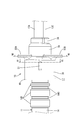
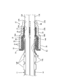
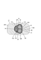
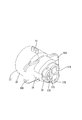
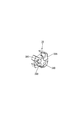
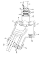
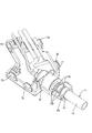
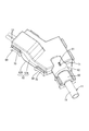
- FIG. IV-IV sectional view in FIG. Front view showing seal member Sectional view taken along line VI-VI in FIG. Sectional view taken along line VII-VII in FIG.
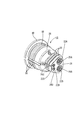
- FIG. 1 Perspective view showing rubber stopper Top view showing rubber stopper Front view showing rubber stopper Rear view showing rubber stopper Perspective view showing a cap Rear view showing cap
- FIG. 1 Perspective view showing rubber stopper Top view showing rubber stopper Front view showing rubber stopper Rear view showing rubber stopper Perspective view showing a cap Rear view showing cap
- FIG. 1 Perspective view showing rubber stopper Top view showing rubber stopper Front view showing rubber stopper Rear view showing rubber stopper Perspective view showing a cap Rear view showing cap
- FIG. 1 The perspective view which shows the state which attached the guide member to the several electric wire in the multicore cable by which the sheath was peeled off
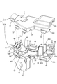
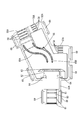
- the perspective view which shows the state which made the rubber stopper fit in the edge part of the sheath of a multicore cable Exploded perspective view of holder Top view of lower holder Top view of lower holder with multi-core cable with sealing member attached Bottom view of the upper holder with a multi-core cable attached with a seal member
- FIGS. 1 to 23 One embodiment will be described with reference to FIGS. 1 to 23.
- the present embodiment can be used, for example, for a wire harness for an electric parking brake mounted on a vehicle (not shown).
- the right side in FIG. 2 is the front and the left side is the rear.
- the upper side in FIG. 3 is the upper side, and the lower side is the lower side.
- symbol may be attached
- the seal structure 12 holds the multicore cable 11, the seal member 10 attached to the end portion 14 ⁇ / b> A of the sheath 14 of the multicore cable 11, and the multicore cable 11 and the seal member 10.
- a holder 52 As shown in FIG. 23, the seal structure 12 holds the multicore cable 11, the seal member 10 attached to the end portion 14 ⁇ / b> A of the sheath 14 of the multicore cable 11, and the multicore cable 11 and the seal member 10.
- the multicore cable 11 includes a sheath 14 made of a synthetic resin in which a plurality of electric wires 13A, 13B, 13C, and 13D (four in this embodiment) are insulative. It is an enclosed structure.
- the electric wires 13A, 13B, 13C, and 13D have a configuration in which the outer periphery of a metal core wire (not shown) is covered with a synthetic resin insulating coating (not shown).
- the cross-sectional shape of the multicore cable 11 is circular.
- the electric wires 13A, 13B, 13C, and 13D are referred to as the electric wires 13 when described without distinction.
- the four electric wires 13A, 13B, 13C, and 13D include two types of electric wires 13A, 13B, 13C, and 13D having different outer diameter dimensions.
- a first electric wire 13A and a second electric wire 13B connected to a motor for an electric parking brake, a third electric wire 13C for an anti-lock brake system sensor, and a fourth electric wire 13D are included.
- the cross-sectional shapes of the first electric wire 13A, the second electric wire 13B, the third electric wire 13C, and the fourth electric wire 13D are circular.
- the outer diameter of the first electric wire 13A and the second electric wire 13B is set larger than the outer diameter of the third electric wire 13C and the fourth electric wire 13D.
- the outer diameter of the first electric wire 13A and the outer diameter of the second electric wire 13B are set to be the same.
- the outer diameter dimension of the third electric wire 13C and the outer diameter dimension of the fourth electric wire 13D are set to be the same.
- a first electric wire 13A, a second electric wire 13B, a third electric wire 13C, and a fourth electric wire 13D are led out from the end portion 14A of the sheath 14 of the multicore cable 11 and branched.
- a plurality of (three in this embodiment) sheath side ribs 14B projecting outward and extending in the circumferential direction are provided at predetermined positions near the end 14A of the sheath 14. Is provided.
- the sheath side rib 14B is provided integrally with the sheath 14 by projecting the sheath 14 outward.
- These three sheath-side ribs 14B have a predetermined width dimension in the extending direction of the multi-core cable 11 (left and right direction in FIG. 3), and are provided at predetermined intervals. More specifically, the width dimension of the sheath side rib 14B in the extending direction of the multicore cable 11 is such that the sheath side rib 14B located on the end portion 14A side of the sheath 14 is located on the opposite side to the end portion 14A. It is set smaller than the sheath side rib 14B. In other words, the width dimension of the sheath-side rib 14B in the extending direction of the multicore cable is set so as to increase in order as the distance from the end 14A of the sheath 14 increases. Moreover, the width dimension of the groove part 14C between adjacent sheath side rib 14B is set so that it may become an equivalent dimension, respectively.
- seal member 10 As shown in FIGS. 1 to 4, in the end portion 14A of the sheath 14 of the multi-core cable 11, there is a region where the first electric wire 13A, the second electric wire 13B, the third electric wire 13C, and the fourth electric wire 13D are branched. A seal member 10 is attached. The seal member 10 prevents liquid such as water and oil from entering the sheath 14 from the end portion 14A of the sheath 14.
- the seal member 10 includes a rubber stopper 15 attached to the end portion 14 ⁇ / b> A of the sheath 14, a guide member 16 attached to the inside of the rubber stopper 15, and a cap 17 fitted on the rubber stopper 15.
- a rubber plug 15 is attached to the end portion 14 ⁇ / b> A of the sheath 14.
- the rubber plug 15 has a sheath outer fitting portion 18 that is fitted on the end portion 14 ⁇ / b> A of the sheath 14.
- the sheath outer fitting portion 18 is formed in a hood shape that opens toward the rear side (left side in FIG. 3).
- the sheath outer fitting portion 18 is formed in a substantially cylindrical shape in a natural state.
- a flange portion 19 that protrudes outward in the radial direction of the sheath outer fitting portion 18 is formed at the rear edge of the sheath outer fitting portion 18.
- a plurality of sheath side lips 20 projecting inward are annularly provided along the circumferential direction of the sheath outer fitting portion 18 on the inner circumference of the sheath outer fitting portion 18. Is formed.
- the sheath side lip 20 is in close contact with the outer periphery of the sheath 14 in a state where the sheath outer fitting portion 18 is fitted on the end portion 14 ⁇ / b> A of the sheath 14. Thereby, the gap between the rubber plug 15 and the sheath 14 is sealed.
- the first electric wire 13 ⁇ / b> A, the second electric wire 13 ⁇ / b> B, the third electric wire 13 ⁇ / b> C, and the fourth electric wire are disposed at the front end (right side in FIG. 3) of the rubber plug 15.
- An electric wire penetrating portion 21 having a plurality of (four in this embodiment) through holes 22A, 22B, 22C, and 22D through which each of the electric wires 13D passes is provided.
- the plurality of through holes 22A, 22B, 22C, and 22D are penetrated by the first through hole 22A through which the first electric wire 13A passes, the second through hole 22B through which the second electric wire 13B passes, and the third electric wire 13C.
- the cross-sectional shape of the wire penetration portion 21 is formed in a trapezoidal shape with rounded corners.
- the cross-sectional shape of the wire penetrating portion 21 includes a long side 23 extending in the vertical direction, a short side 24 parallel to the long side 23 and shorter than the long side 23, an end of the long side 23, and an end of the short side 24. And two hypotenuses 25 connecting the sections.
- a first through hole 22A and a second through hole 22B are formed side by side along the direction in which the long side 23 extends (vertical direction) at a position near the long side 23. Further, in the wire penetration part 21, a third through hole 22 ⁇ / b> C and a fourth through hole 22 ⁇ / b> D are formed side by side along the direction (vertical direction) in which the short side 24 extends at a position near the short side 24.
- the inner diameter of the first through hole 22A is slightly larger than the outer diameter of the first electric wire 13A.
- the first electric wire side lip 26 ⁇ / b> A that is in close contact with the outer periphery of the first electric wire 13 ⁇ / b> A has an annular shape along the circumferential direction of the first through hole 22 ⁇ / b> A. Is formed.
- the first electric wire side lip 26A is in close contact with the outer periphery of the first electric wire 13A in a state where the first electric wire 13A is penetrated into the first through hole 22A. Thereby, the space between the first electric wire 13A and the rubber plug 15 is sealed.
- the inner diameter dimension of the second through hole 22B is slightly larger than the outer diameter dimension of the second electric wire 13B.
- the second electric wire side lip 26 ⁇ / b> B that is in close contact with the outer periphery of the second electric wire 13 ⁇ / b> B has an annular shape along the circumferential direction of the second through hole 22 ⁇ / b> B. Is formed.
- the 2nd electric wire side lip 26B is closely_contact
- the inner diameter dimension of the third through hole 22C is formed to be slightly larger than the outer diameter dimension of the third electric wire 13C.
- a third electric wire side lip 26 ⁇ / b> C that is in close contact with the outer periphery of the third electric wire 13 ⁇ / b> C is annular along the circumferential direction of the third through hole 22 ⁇ / b> C. Is formed.
- the third electric wire side lip 26C comes into close contact with the outer periphery of the third electric wire 13C in a state where the third electric wire 13C is penetrated into the third through hole 22C. Thereby, the space between the third electric wire 13C and the rubber plug 15 is sealed.
- the inner diameter dimension of the fourth through hole 22D is formed to be slightly larger than the outer diameter dimension of the fourth electric wire 13D.
- a fourth electric wire side lip 26 ⁇ / b> D that is in close contact with the outer periphery of the fourth electric wire 13 ⁇ / b> D is annular along the circumferential direction of the fourth through hole 22 ⁇ / b> D. Is formed.
- the fourth electric wire side lip 26D is in close contact with the outer periphery of the fourth electric wire 13D in a state in which the fourth electric wire 13D is passed through the fourth through hole 22D. Thereby, the space between the fourth electric wire 13D and the rubber plug 15 is sealed.
- the rubber plug 15 includes the first electric wire 13 ⁇ / b> A, the first electric wire 13 ⁇ / b> A, and the first electric wire 13 ⁇ / b> A at the position inside the sheath outer fitting portion 18 and between the sheath side lip 20 and the electric wire penetration portion 21.
- a guide member 16 described later having a plurality of (four in this embodiment) guide holes 38A, 38B, 38C, and 38D through which the two electric wires 13B, the third electric wires 13C, and the fourth electric wires 13D are inserted is held.
- a holding portion 28 is formed.
- Cap 17 As shown in FIGS. 3 and 4, a synthetic resin cap 17 is fitted on the rubber plug 15.
- the cap 17 opens toward the rear side (left side in FIG. 3), and is externally fitted to the rubber plug 15 from the front side (right side in FIG. 3).
- the opening edge of the cap 17 is in contact with the flange portion 19 of the rubber plug 15.
- the opening side (left side in FIG. 3) of the cap 17 is a large-diameter portion 30 that is fitted on the sheath fitting portion 18 of the rubber plug 15. As shown in FIGS. 6 and 13, the cross-sectional shape of the large-diameter portion 30 is formed in a circular shape following the outer shape of the sheath outer fitting portion 18.
- the inner periphery of the large-diameter portion 30 is in close contact with a plurality of (three in this embodiment) large-diameter portion side lips 31 formed on the outer periphery of the sheath outer fitting portion 18. It has become. As shown in FIGS. 8 and 9, the large-diameter portion side lip 31 protrudes outward on the outer peripheral surface of the sheath outer fitting portion 18 and is formed along the circumferential direction of the sheath outer fitting portion 18. .
- the large diameter portion 30 of the cap 17 is fitted on the sheath outer fitting portion 18 of the rubber plug 15, and the large diameter portion 30 is connected to the sheath outer fitting portion 18.
- the sheath outer fitting portion 18 is pressed inward in the radial direction. Thereby, the sheath outer fitting portion 18 is pressed against the outer periphery of the sheath 14 from the outside. As a result, the sheath-side lip 20 of the sheath outer fitting portion 18 is securely brought into close contact with the outer periphery of the sheath 14.
- a small-diameter portion 34 that is externally fitted to the wire penetration portion 21 of the rubber plug 15 is provided in front of the large-diameter portion 30 (on the right side in FIG. 3).
- the outer diameter dimension of the small diameter part 34 is set smaller than the outer diameter dimension of the large diameter part 30.
- the cross-sectional shape of the small diameter portion 34 is formed in a trapezoidal shape with rounded corners following the outer shape of the wire penetration portion 21.
- the inner periphery of the small diameter portion 34 comes into close contact with a plurality of (three in this embodiment) small diameter portion lips 35 formed on the outer periphery of the wire penetration portion 21. Yes.
- the small-diameter portion side lip 35 protrudes outward on the outer peripheral surface of the wire penetration portion 21 and is formed along the circumferential direction of the wire penetration portion 21.
- the small diameter portion 34 of the cap 17 in a state where the small diameter portion 34 of the cap 17 is externally fitted to the electric wire penetration portion 21 of the rubber plug 15, the small diameter portion 34 changes the electric wire penetration portion 21 and the diameter of the electric wire penetration portion 21. It pushes inward in the direction. Thereby, the electric wire penetration part 21 is compressed from the outside. As a result, the first to fourth electric wire side lips 26A, 26B, 26C, and 26D formed on the inner periphery of the first to fourth through holes 22A, 22B, 22C, and 22D are connected to the first to fourth electric wires 13A and 13B. , 13C, and 13D are securely in close contact with the outer peripheries.
- the cap 17 includes a rear wall 36 on the front side (right side in FIG. 3) of the small diameter portion 34.
- a first lead-out hole in which the first electric wire 13 ⁇ / b> A, the second electric wire 13 ⁇ / b> B, the third electric wire 13 ⁇ / b> C, and the fourth electric wire 13 ⁇ / b> D are led out from the cap 17.
- 37A, a second outlet hole 37B, a third outlet hole 37C, and a fourth outlet hole 37D are formed through the back wall 36.
- the cap 17 is formed with two locking projections 50 ⁇ / b> A and 50 ⁇ / b> B that protrude outward in the radial direction of the small diameter portion 34 from the outer surface of the small diameter portion 34.
- the two locking projections 50A and 50B one locking projection 50A protrudes from the long side 23 side of the small diameter portion 34, and the other locking projection 50B protrudes from the short side 24 side of the small diameter portion 34.
- the two locking projections 50A and 50B have a plate shape, and have a generally rectangular shape as a whole.
- the cap 17 is formed with an anti-rotation protrusion 51 protruding upward on the outer periphery of the large diameter portion 30.
- the anti-rotation protrusion 51 has a rib shape extending in the extending direction of the large diameter portion 30 (left and right direction in FIG. 2).
- the guide member 16 is made of synthetic resin, and as shown in FIGS. 6 and 14, a first guide hole 38A through which the first electric wire 13A is inserted and a second guide hole 38B through which the second electric wire 13B is inserted.
- the third guide hole 38C through which the third electric wire 13C is inserted and the fourth guide hole 38D through which the fourth electric wire 13D is inserted are penetrated.
- the multi-core cable 11 with the seal member 10 attached to the end of the sheath 14 is mounted in the holder 52.
- the holder 52 includes a lower holder 52A and an upper holder 52B assembled to the lower holder 52A.
- the lower holder 52 ⁇ / b> A includes a bottom wall and a side wall that rises upward from a side edge of the bottom wall.
- a motor wire outlet 55A from which the first electric wire 13A and the second electric wire 13B are led out and a sensor electric wire outlet 56A from which the third electric wire 13C and the fourth electric wire 13D are led out are semicircular. It is depressed and opened.
- a spare outlet for a wire (not shown) connected to a device different from the motor or the sensor is provided on a side wall different from the side wall where the motor wire outlet 55A and the sensor wire outlet 56A are formed.
- 57A is depressed in a semicircular shape and opened.
- a plurality of holding grooves 58 for holding a corrugated tube are formed on the inner peripheral surfaces of the motor electric wire outlet 55A, the sensor electric wire outlet 56A, and the auxiliary outlet 57A.
- an extended portion 59A that protrudes outward is formed on a side wall different from that in which the motor wire outlet 55A, the sensor wire outlet 56A, and the preliminary outlet 57A are formed.
- the cross-sectional shape of the extending portion 59A is formed in a substantially semicircular shape.
- the distal end side of the extending portion 59 ⁇ / b> A is a sheath holding portion 60 that holds the sheath 14 of the multicore cable 11.
- the sheath holding part 60 is formed with holder-side ribs 61 that protrude inward and extend in the circumferential direction of the sheath holding part 60.
- a plurality of (four in the present embodiment) holder-side ribs 61 are formed side by side with an interval in the extending direction of the extending portion 59A (the left-right direction in FIG. 18).
- These four holder-side ribs 61 are provided with a width dimension and an interval in which the three sheath-side ribs 14B provided on the outer periphery of the sheath 14 described above are fitted. More specifically, the four holder-side ribs 61 are provided at both ends in the extending direction of the sheath holding portion 60 and between them, and the distal end side of the extending portion 59A is sparse, and the proximal end side is provided. Are arranged so as to be dense.
- the three sheath-side ribs 14B of the sheath 14 are respectively fitted between the adjacent holder-side ribs 61 so as to be concavo-convexly fitted.
- the groove 14C of the sheath 14 is fitted into the groove 14C so that the sheath 14 is held so as not to come out of the sheath holding portion 60. That is, the relative position between the multicore cable 11 and the holder 52 is prevented from shifting (see FIGS. 19 and 23).
- maintenance part 60 is set to the dimension in which the sheath 14 is accommodated, without shaking in radial direction.
- a cap holding portion 62 (an example of a seal member holding portion) for holding the cap 17 is formed from the proximal end side of the extending portion 59A to a position slightly inside the extending portion 59A of the lower holder 52A. Yes.
- the large diameter part 30 of the cap 17 is accommodated in the base end side of the extending part 59A in the cap holding part 62.
- the size of the portion in which the large-diameter portion 30 is accommodated is set to a size in which the large-diameter portion 30 is accommodated without rattling in the radial direction (see FIGS. 19 and 20).
- a partition wall 63 protruding upward from the bottom wall is formed at a position inside the side wall of the cap holding portion 62, and a small diameter portion of the cap 17 is formed in a region surrounded by the partition wall 63. 34 is accommodated.
- the partition wall 63 has a locking groove 64 into which the locking projections 50A and 50B are inserted at positions corresponding to the locking projections 50A and 50B of the cap 17 in a state where the cap 17 is housed inside the partition wall 63. It is formed extending downward from the upper edge of the partition wall 63.
- the locking projections 50A and 50B are inserted into the locking groove 64 in a state where the cap 17 is accommodated in the cap holding part 62. As a result, the locking protrusions 50A and 50B come into contact with the inner surface of the locking groove 64 from the thickness direction of the locking protrusions 50A and 50B, so that the relative positions of the cap 17 and the holder 52 are shifted. This is suppressed (see FIG. 19).
- the locking groove 64 is formed in the partition 63 at a position slightly inside the side wall of the lower holder 52A. Thereby, the force applied to the cap 17 is received by the side wall of the lower holder 52A.
- the width dimension of the locking groove 64 is set to be the same as or slightly larger than the thickness dimension of the locking protrusions 50A and 50B.
- An inclined surface for guiding the locking protrusions 50 ⁇ / b> A and 50 ⁇ / b> B is formed on the opening edge portion of the locking groove 64 so as to expand the diameter upward.
- maintenance parts 62 is set to the dimension in which the large diameter part 30 is accommodated without shaking in a radial direction and an extension direction.
- the bottom wall of the lower holder 52A has a plurality of first to fourth electric wires 13A led out from the first to fourth through holes 22A, 22B, 22C, 22D of the rubber plug 15.
- 13B, 13C, 13D are formed with a first electric wire routing portion 65A and a second electric wire routing portion 65B for guiding them along a predetermined routing route.
- the first electric wire arrangement portion 65A and the second electric wire arrangement portion 65B are formed in a wall shape that rises upward from the bottom wall.
- the second electric wire routing portion 65B is provided on the side close to the sensor electric wire outlet 56A.
- the first electric wire routing portion 65A and the second electric wire routing portion 65B are formed by gently bending from a position near the cap holding portion 62 to a position near the motor wire outlet 55A.
- 65 A of 1st electric wire routing parts and the 2nd electric wire routing part 65B are formed in the substantially S shape seeing from upper direction.
- the first electric wire 13A and the second electric wire 13B are accommodated between the first electric wire arrangement portion 65A and the second electric wire arrangement portion 65B.
- the first electric wire 13A and the second electric wire 13B are routed along the routing route from the cap 17 to the motor wire outlet 55A.
- a guide protrusion 66 extending toward the sensor electric wire outlet 56A is formed at a position in the vicinity of the sensor electric wire outlet 56A.
- the third electric wire 13C and the fourth electric wire 13D led out from the cap 17 are guided by coming into contact with the second electric wire routing portion 65B and the guide projection 66, and reach from the cap 17 to the sensor electric wire outlet 56A. It is routed along the route.
- a bracket 67 is formed on the side wall of the lower holder 52A so as to protrude downward (see FIG. 17).
- a bolt insertion hole 68 is formed through the bracket 67.
- a bolt (not shown) is inserted into the bolt insertion hole 68 and screwed to the vehicle, whereby the holder 52 is fixed to the vehicle.
- the upper holder 52 ⁇ / b> B includes an upper wall and a side wall that extends downward from an edge of the upper wall.
- a plurality of lock receiving portions 70 are formed at positions corresponding to the plurality of lock portions 69 formed on the side wall of the lower holder 52A.
- the lower holder 52A and the upper holder 52B are assembled by elastically engaging the lock portion 69 and the lock receiving portion 70 (see FIG. 22).
- the motor wire outlet 55A, the sensor wire outlet 56A, the preliminary outlet 57A, and the extension of the lower holder 52A A motor wire outlet 55B, a sensor wire outlet 56B, a preliminary outlet 57B, and an extending portion 59B are formed at positions corresponding to the portion 59A.
- a holding unit 60 is provided. Specifically, a plurality of (four in this embodiment) holder-side ribs 61 projecting inward and extending in the circumferential direction of the sheath holding portion 60 are formed at a predetermined interval on the sheath holding portion 60 of the upper holder 52B. It is formed side by side.
- a plurality (four in this embodiment) of holder-side ribs 61 are arranged at intervals in the extending direction of the extending portion 59B, and when the upper holder 52B is assembled to the lower holder 52A, the holder side of the lower holder 52A It is set so as to be continuous with the rib 61.
- the extension portion 59B of the upper holder 52B is formed with a rotation stop hole 71 penetrating at a position corresponding to the rotation stop protrusion 51 of the cap 17 in a state where the cap 17 is accommodated in the cap holding portion 62. (See FIG. 17 and FIG. 22).
- the anti-rotation protrusion 51 is inserted into the anti-rotation hole 71, and the anti-rotation protrusion 51 contacts the inner peripheral surface of the anti-rotation hole 71, so that the cap 17 has a large diameter portion of the cap 17 in the cap holding portion 62. The rotation in the circumferential direction of 30 is suppressed.
- the cap 17 (the seal member 10) can be reliably aligned with respect to the holder 52 in the vertical direction.
- the first to fourth electric wires 13A, 13B, 13C, 13D led out from the cap 17, and the first electric wire routing portion 65A and the second electric wire routing portion 65B can be easily aligned. .
- cap holding portions 62 and locking grooves 64 of the same form are formed at positions corresponding to the cap holding portions 62 and the locking grooves 64 of the lower holder 52A.
- the sheath 14 of the multicore cable 11 is peeled off by a known method.
- the first to fourth electric wires 13A, 13B, 13C, and 13D are led out from the end portion 14A of the sheath 14.
- the first to fourth electric wires 13A, 13B, 13C, and 13D are inserted into the first to fourth guide holes 38A, 38B, 38C, and 38D of the guide member 16, respectively.
- the fourth electric wire 13D is inserted through 38D.
- the first to fourth electric wires 13A, 13B, 13C, and 13D are inserted into the first to fourth through holes 22A, 22B, 22C, and 22D of the rubber plug 15, respectively.
- the first electric wire 13A is inserted through the first through hole 22A
- the second electric wire 13B is inserted through the second through hole 22B
- the third electric wire 13C is inserted through the third through hole 22C
- the fourth through hole is inserted.
- the fourth electric wire 13D is inserted through 22D.
- the rubber stopper 15 is moved to the position of the guide member 16.
- the first to fourth through holes 22A, 22B, 22C, 22D of the rubber plug 15 and the first to fourth guide holes 38A, 38B, 38C, 38D of the guide member 16 are aligned with each other.
- the relative positions of the rubber plug 15 and the guide member 16 are adjusted so as to be arranged.
- the rubber plug 15 is moved to the end portion 14 ⁇ / b> A of the sheath 14, and the sheath external fitting portion 18 of the rubber plug 15 is externally fitted to the end portion 14 ⁇ / b> A of the sheath 14.
- the first to fourth electric wires 13A, 13B, 13C, and 13D are inserted into the first to fourth lead-out holes 37A, 37B, 37C, and 37D of the cap 17, respectively.
- the first electric wire 13A is inserted through the first outlet hole 37A
- the second electric wire 13B is inserted through the second outlet hole 37B
- the third electric wire 13C is inserted through the third outlet hole 37C
- the fourth outlet hole is inserted.
- the fourth electric wire 13D is inserted through 37D.
- the cap 17 is moved to the position of the rubber plug 15 fitted on the end 14 ⁇ / b> A of the sheath 14.
- the first to fourth through holes 22A, 22B, 22C, 22D of the rubber plug 15 and the first to fourth outlet holes 37A, 37B, 37C, 37D of the cap 17 are aligned with each other.
- the relative positions of the rubber plug 15 and the cap 17 are adjusted so that With the first through fourth through holes 22A, 22B, 22C, 22D of the rubber plug 15 and the first through fourth outlet holes 37A, 37B, 37C, 37D of the cap 17 aligned, the cap 17 Is externally fitted to the rubber plug 15. Thereafter, the cap 17 is pushed in until it comes into contact with the flange portion 19 of the rubber plug 15 (see FIGS. 1 and 2).
- the sheath 14 of the multicore cable 11 is placed on the sheath holding portion 60 of the lower holder 52A.
- the plurality of sheath side ribs 14 ⁇ / b> B provided on the outer periphery of the sheath 14 are placed so as to fit into predetermined recesses between the plurality of holder side ribs 61.
- the plurality of sheath side ribs 14B are set to have different width dimensions, and the holder side ribs 61 are also arranged at different intervals in accordance with the sheath side ribs 14B. It is difficult to arrange and easy to align.
- the cap 17 is placed on the cap holding portion 62 in such a posture that the rotation prevention projection 51 of the cap 17 faces upward. At this time, the locking protrusions 50A and 50B of the cap 17 are inserted into the locking groove 64 from above.
- the first electric wire 13A and the second electric wire 13B led out from the cap 17 are arranged between the first electric wire routing portion 65A and the second electric wire routing portion 65B, and are distributed to the motor electric wire outlet 55A.
- the third electric wire 13C and the fourth electric wire 13D led out from the cap 17 are routed to the sensor electric wire outlet 56A while being along the second electric wire routing portion 65B and the guide protrusion 66.
- the upper holder 52B is assembled to the lower holder 52A from above.
- the upper holder 52B and the lower holder 52A are assembled together by elastically engaging the lock portion 69 and the lock receiving portion 70 (see FIG. 22).
- the plurality of sheath-side ribs 14B provided on the outer periphery of the sheath 14 fit into predetermined recesses between the plurality of holder-side ribs 61 of the upper holder 52B, and the seal structure 12 of the multicore cable 11 is completed.
- the anti-rotation protrusion 51 of the cap 17 is fitted into the anti-rotation hole 71 of the upper holder 52B.
- sheath side rib 14B is provided integrally with the sheath 14 by projecting the sheath 14 outward, the number of parts is reduced. Further, since the sheath side rib 14B does not move with respect to the sheath 14 as compared with the configuration in which the sheath side rib 14B is formed by attaching a member separate from the sheath 14 to the sheath 14, more reliably, The removal of the sheath 14 from the holder 52 can be suppressed.
- the seal member 10 is composed of the rubber plug 15 and the cap 17 fitted on the rubber plug 15, the seal member 10 has high adhesion to the electric wire 13 and hardly deforms. Moreover, since the sheath 14 is held by the sheath holding portion 60 and the cap 17 is held by the cap holding portion 62, the relative position between the sheath 14 and the cap 17 is held. The branch portions of the first to fourth electric wires 13A, 13B, 13C, and 13D in the multicore cable 11 can be more reliably sealed.
- the number, width, position, and range of the sheath-side rib 14B and the holder-side rib 61 are not limited to the above-described embodiment.
- the sheath-side rib 14B and the holder-side rib 61 are concavo-convexly fitted. If it is set to.
- either one of the sheath-side rib 14B and the holder-side rib 61 may be single and may be fitted between the other-side ribs, or may be provided with many ribs.
- the sheath side rib 14B and the holder side rib 61 may be provided only in a portion corresponding to a part of the sheath holding portion 60.
- the sheath side rib 14B is integrally provided with the sheath 14.
- a resin or metal ring separate from the sheath 14 is crimped to the sheath 14 or bonded. It is good also as a structure provided by doing.
- the seal member 10 is configured by the rubber plug 15 and the cap 17 that is fitted on the rubber plug 15, but may be configured by only the rubber plug 15.
- the plurality of wires arranged in the multi-core cable 11 may be two to three, or five or more.
- the plurality of electric wires are configured to include electric wires having two types of outer diameters, but are not limited thereto, and may be configured to include electric wires having three or more types of outer diameters. All may be the same electric wire.
- the electric wire may be a shielded electric wire.
- the electric wire may be a stranded wire provided with a core wire in which a plurality of fine metal wires are twisted together, or may be a so-called single core wire having a metal rod as a core wire.
- arbitrary electric wires can be appropriately selected as necessary.
- the multi-core cable 11 may be a so-called cabtyre cable, or may be a multi-core shielded electric wire in which the outer periphery of a plurality of electric wires is surrounded by a shield layer.
- cabtyre cable or may be a multi-core shielded electric wire in which the outer periphery of a plurality of electric wires is surrounded by a shield layer.
- an arbitrary multicore cable can be appropriately selected as necessary.
- any liquid such as water, oil, organic solvent or the like can be sealed as necessary.
- Seal member 11 Multi-core cable 12: Seal structure 13: Electric wire 14: Sheath 14B: Sheath side rib 15: Rubber plug (seal member) 17: Cap (seal member) 52: Holder 60: Sheath holding part 61: Holder side rib 62: Cap holding part (seal member holding part)
Landscapes
- Connector Housings Or Holding Contact Members (AREA)
- Details Of Connecting Devices For Male And Female Coupling (AREA)
Abstract
第1~第4電線13A,13B,13C,13Dがシース14で包囲されると共にシース14の端部14Aから第1~第4電線13A,13B,13C,13Dが導出された多芯ケーブル11と、第1~第4電線13A,13B,13C,13Dのそれぞれが貫通されると共にシース14の端部14Aに外嵌されるシール部材10と、シース14を保持するシース保持部60を有すると共にシール部材10を保持するキャップ保持部62を有するホルダ52と、を備え、シース14には、外側に向けて突出して周方向に伸びるシース側リブ14Bが設けられるとともに、シース保持部60には、内側に向けて突出するホルダ側リブ61が設けられており、シース側リブ14Bおよびホルダ側リブ61のうち少なくとも一方側が複数設けられており、複数の一方側の間に他方側が嵌合している多芯ケーブル11のシール構造12。
Description
本明細書に開示される技術は、多芯ケーブルのシール構造に関する。
従来、複数の電線を一括して防水処理する方法として、複数の電線がそれぞれ挿通される複数の電線挿通孔を有するゴム栓が知られている。各電線の外周と、各電線挿通孔の内周とが密着することにより、各電線とゴム栓とがシールされるようになっている。
このような一括型のゴム栓を、複数の電線がシースで包囲された多芯ケーブルの端末部分に取り付ける場合には、仮想的な技術として、ゴム栓にシースの端部に外嵌されるシース外嵌部を一体に設ける構成が考えられる。しかしこのような構成においては、例えば、比較的に強い力が電線に加えられた場合に、電線に引っ張られてゴム栓の多芯ケーブルに対する姿勢が傾いてしまい、その結果、電線の外周と、電線挿通孔の内周との密着性が低下して、電線とゴム栓とのシール性が低下する虞がある。
そこで、仮想的な技術として、多芯ケーブルのシースを保持するシース保持部と、ゴム栓を保持するゴム栓保持部を有するホルダに、ゴム栓を取り付けた多芯ケーブルの末端部を保持させ、シースとゴム栓との相対的な位置を保持することにより、電線とゴム栓とのシール性を保持する構成が考えられる。これにより、多芯ケーブルにおける複数の電線の分岐部分を確実にシールすることが期待された。
ところで、上記の仮想的な技術によると、シースに対して外部から引っ張る力が作用した場合でも、シースがホルダのシース保持部から抜けないようにするために、シース保持部にある程度の保持力を持たせることが必要である。しかし、保持力を高くしようとすると、多芯ケーブルをホルダに組み付ける際の組み付け荷重が高くなるため、組み付け作業が困難になるという問題がある。また、シースに対して大きな荷重を付加すると、電線を変形させてしまう虞もある。
本明細書に開示される技術は、上記のような事情に基づいて完成されたものである。
本明細書に開示される多芯ケーブルのシール構造は、複数の電線がシースで包囲されると共に前記シースの端部から前記複数の電線が導出された多芯ケーブルと、前記複数の電線のそれぞれが貫通されると共に前記シースの端部に外嵌されるシール部材と、前記シースを保持するシース保持部を有すると共に前記シール部材を保持するシール部材保持部を有するホルダと、を備え、前記シースには、外側に向けて突出して周方向に伸びるシース側リブが設けられるとともに、前記シース保持部には、内側に向けて突出するホルダ側リブが設けられており、前記シース側リブおよび前記ホルダ側リブのうち少なくとも一方側が複数設けられており、複数の前記一方側の間に他方側が嵌合している。
上記構成によれば、シースに対してホルダから引き抜く方向に力が加えられた場合でも、シース側リブとホルダ側リブとの凹凸嵌合により、シースのホルダからの抜けを抑制することができる。しかも、シースを強固に締め付けてホルダに保持する構成と比較して、シースに対して大きい荷重を付加することがないので、電線を変形させることがない。また、組み付け作業も大きな力を要することがないので、容易である。
上記多芯ケーブルのシール構造は、以下の構成を有してもよい。
シース側リブは、シースを外側に向けて突出させることによりシースと一体的に設けられていてもよい。このような構成とすると、部品点数が少なくなる。また、シースと別体の部材をシースに取り付けることでシース側リブを形成する構成と比較して、シース側リブがシースに対してずれ動くことがないから、より確実に、シースのホルダからの抜けを抑制することができる。
シール部材は、複数の電線のそれぞれが貫通されると共にシースの端部に外嵌されるゴム栓と、ゴム栓に外嵌されてゴム栓を内方に押圧するキャップと、を備えており、シール部材保持部は、キャップを保持するキャップ保持部である構成としてもよい。
このような構成とすると、シール部材が変形し難くなるため、多芯ケーブルにおける複数の電線の分岐部分とシール部材とのシール性がより向上する。
本明細書に開示された技術によれば、組み付け作業が容易で、電線を変形させることがなく、高い保持力でホルダに保持することができる多芯ケーブルのシール構造を得ることができる。
一実施形態を、図1ないし図23を参照しつつ説明する。本実施形態は、例えば、車両(図示せず)に搭載された、電気パーキングブレーキ用のワイヤーハーネスに使用することができる。なお、以下の説明において、図2における右側を前方とし、左側を後方とする。また、図3における上側を上方とし、下側を下方とする。さらに、複数の同一部材については、一の部材に符号を付し、他の部材については符号を省略することがある。
図23に示すように、シール構造12は、多芯ケーブル11と、多芯ケーブル11のシース14の端部14Aに取り付けられたシール部材10と、多芯ケーブル11とシール部材10とを保持するホルダ52と、を備える。
(多芯ケーブル11)
図1~図4に示すように、本実施形態に係る多芯ケーブル11は、複数の電線13A,13B,13C,13D(本実施形態では4つ)が絶縁性の合成樹脂製のシース14で包囲された構成となっている。電線13A,13B,13C,13Dは、金属製の芯線(図示せず)の外周が合成樹脂製の絶縁被覆(図示せず)で覆われた構成となっている。多芯ケーブル11の断面形状は円形状をなしている。以下、電線13A,13B,13C,13Dを区別せずに記載する場合は、電線13とする。
図1~図4に示すように、本実施形態に係る多芯ケーブル11は、複数の電線13A,13B,13C,13D(本実施形態では4つ)が絶縁性の合成樹脂製のシース14で包囲された構成となっている。電線13A,13B,13C,13Dは、金属製の芯線(図示せず)の外周が合成樹脂製の絶縁被覆(図示せず)で覆われた構成となっている。多芯ケーブル11の断面形状は円形状をなしている。以下、電線13A,13B,13C,13Dを区別せずに記載する場合は、電線13とする。
図6及び図7に示すように、4本の電線13A,13B,13C,13Dは、異なる外径寸法を有する2種の電線13A,13B,13C,13Dを含む。本実施形態においては、電気パーキングブレーキ用のモータに接続される第1電線13A、及び第2電線13Bと、アンチロックブレーキシステムのセンサ用の第3電線13C、及び第4電線13Dが含まれる。第1電線13A、第2電線13B、第3電線13C、及び第4電線13Dの断面形状は円形状をなしている。
第1電線13Aと第2電線13Bの外径寸法は、第3電線13Cと第4電線13Dの外径寸法よりも大きく設定されている。第1電線13Aの外径寸法と、第2電線13Bの外径寸法とは同じに設定されている。また、第3電線13Cの外径寸法と、第4電線13Dの外径寸法とは同じに設定されている。多芯ケーブル11のシース14の端部14Aからは第1電線13A、第2電線13B、第3電線13C、及び第4電線13Dが導出されて、それぞれ分岐されている。
図2~図4に示すように、シース14の端部14A寄りの所定位置には、外側に向けて突出して周方向に沿って伸びる複数(本実施形態では3本)のシース側リブ14Bが設けられている。シース側リブ14Bは、シース14を外側に向けて突出させることにより、シース14と一体的に設けられている。
これら3つのシース側リブ14Bは、多芯ケーブル11の延びる方向(図3における左右方向)について、それぞれ所定の幅寸法を有しているとともに、所定の間隔を空けて設けられている。より詳細には、シース側リブ14Bの、多芯ケーブル11の延びる方向についての幅寸法は、シース14の端部14A側に位置するシース側リブ14Bの方が、端部14Aと反対側に位置するシース側リブ14Bよりも小さく設定されている。換言すると、シース側リブ14Bの、多芯ケーブルの延びる方向についての幅寸法は、シース14の端部14Aから離れるに従って、順に大きくなるように設定されている。また、隣り合うシース側リブ14Bの間の溝部14Cの幅寸法は、それぞれ同等の寸法になるように設定されている。
(シール部材10)
図1~図4に示すように、多芯ケーブル11のシース14の端部14Aにおいて、第1電線13A、第2電線13B、第3電線13C、及び第4電線13Dが分岐された領域には、シール部材10が取り付けられている。シール部材10によって、シース14の端部14Aから水、油等の液体がシース14内に浸入することが抑制されるようになっている。シール部材10は、シース14の端部14Aに取り付けられるゴム栓15と、ゴム栓15の内部に取り付けられるガイド部材16と、ゴム栓15に外嵌されるキャップ17と、を備える。
図1~図4に示すように、多芯ケーブル11のシース14の端部14Aにおいて、第1電線13A、第2電線13B、第3電線13C、及び第4電線13Dが分岐された領域には、シール部材10が取り付けられている。シール部材10によって、シース14の端部14Aから水、油等の液体がシース14内に浸入することが抑制されるようになっている。シール部材10は、シース14の端部14Aに取り付けられるゴム栓15と、ゴム栓15の内部に取り付けられるガイド部材16と、ゴム栓15に外嵌されるキャップ17と、を備える。
(ゴム栓15)
図3及び図4に示すように、シース14の端部14Aには、ゴム栓15が取り付けられている。ゴム栓15は、シース14の端部14Aに外嵌されるシース外嵌部18を有する。シース外嵌部18は、後方側(図3における左側)に向けて開口するフード状に形成されている。シース外嵌部18は、自然状態において実質的に円筒形状に形成されている。シース外嵌部18の後方側の端縁部には、シース外嵌部18の径方向の外方に突出するフランジ部19が形成されている。
図3及び図4に示すように、シース14の端部14Aには、ゴム栓15が取り付けられている。ゴム栓15は、シース14の端部14Aに外嵌されるシース外嵌部18を有する。シース外嵌部18は、後方側(図3における左側)に向けて開口するフード状に形成されている。シース外嵌部18は、自然状態において実質的に円筒形状に形成されている。シース外嵌部18の後方側の端縁部には、シース外嵌部18の径方向の外方に突出するフランジ部19が形成されている。
図3、図4及び図11に示すように、シース外嵌部18の内周には、内方に突出する複数のシース側リップ20が、シース外嵌部18の周方向に沿って環状に形成されている。シース外嵌部18がシース14の端部14Aに外嵌された状態で、シース側リップ20は、シース14の外周に密着するようになっている。これにより、ゴム栓15と、シース14との間がシールされる。
図3、図4及び図10に示すように、ゴム栓15のうち前方側(図3における右側)の端部には、第1電線13A、第2電線13B、第3電線13C、及び第4電線13Dのそれぞれが貫通される、複数(本実施形態では4つ)の貫通孔22A,22B,22C,22Dを有する電線貫通部21が設けられている。複数の貫通孔22A,22B,22C,22Dは、第1電線13Aが貫通される第1貫通孔22Aと、第2電線13Bが貫通される第2貫通孔22Bと、第3電線13Cが貫通される第3貫通孔22Cと、第4電線13Dが貫通される第4貫通孔22Dと、を含む。
図7および図10に示すように、電線貫通部21の断面形状は、角の丸められた台形状に形成されている。電線貫通部21の断面形状は、上下方向に伸びる長辺23と、この長辺23に平行であって長辺23よりも短い短辺24と、長辺23の端部と短辺24の端部とを連結する2つの斜辺25と、を備える。
電線貫通部21には、長辺23寄りの位置に、第1貫通孔22A及び第2貫通孔22Bが、長辺23の延びる方向(上下方向)に沿って並んで形成されている。また、電線貫通部21には、短辺24寄りの位置に、第3貫通孔22C及び第4貫通孔22Dが、短辺24の延びる方向(上下方向)に沿って並んで形成されている。
第1貫通孔22Aの内径寸法は、第1電線13Aの外径寸法よりもやや大きく形成されている。図8及び図10に示すように、第1貫通孔22Aの内周には、第1電線13Aの外周に密着する第1電線側リップ26Aが、第1貫通孔22Aの周方向に沿って環状に形成されている。第1電線側リップ26Aは、第1貫通孔22Aの内部に第1電線13Aが貫通された状態で、第1電線13Aの外周に密着するようになっている。これより、第1電線13Aとゴム栓15との間がシールされる。
第2貫通孔22Bの内径寸法は、第2電線13Bの外径寸法よりもやや大きく形成されている。図8及び図10に示すように、第2貫通孔22Bの内周には、第2電線13Bの外周に密着する第2電線側リップ26Bが、第2貫通孔22Bの周方向に沿って環状に形成されている。第2電線側リップ26Bは、第2貫通孔22Bの内部に第2電線13Bが貫通された状態で、第2電線13Bの外周に密着するようになっている。これにより、第2電線13Bとゴム栓15との間がシールされる。
第3貫通孔22Cの内径寸法は、第3電線13Cの外径寸法よりもやや大きく形成されている。図8及び図10に示すように、第3貫通孔22Cの内周には、第3電線13Cの外周に密着する第3電線側リップ26Cが、第3貫通孔22Cの周方向に沿って環状に形成されている。第3電線側リップ26Cは、第3貫通孔22Cの内部に第3電線13Cが貫通された状態で、第3電線13Cの外周に密着するようになっている。これにより、第3電線13Cとゴム栓15との間がシールされる。
第4貫通孔22Dの内径寸法は、第4電線13Dの外径寸法よりもやや大きく形成されている。図8及び図10に示すように、第4貫通孔22Dの内周には、第4電線13Dの外周に密着する第4電線側リップ26Dが、第4貫通孔22Dの周方向に沿って環状に形成されている。第4電線側リップ26Dは、第4貫通孔22Dの内部に第4電線13Dが貫通された状態で、第4電線13Dの外周に密着するようになっている。これにより、第4電線13Dとゴム栓15との間がシールされる。
図3及び図4に示すように、ゴム栓15には、シース外嵌部18の内部であって、シース側リップ20と、電線貫通部21との間の位置に、第1電線13A、第2電線13B、第3電線13C、及び第4電線13Dがそれぞれ挿通される複数(本実施形態では4つ)のガイド孔38A,38B,38C,38Dを有する、後述するガイド部材16が保持される保持部28が形成されている。
(キャップ17)
図3及び図4に示すように、ゴム栓15には合成樹脂製のキャップ17が外嵌されている。キャップ17は後方側(図3における左側)に向けて開口しており、ゴム栓15に前方側(図3における右側)から外嵌されている。キャップ17の開口端縁は、ゴム栓15のフランジ部19に当接している。
図3及び図4に示すように、ゴム栓15には合成樹脂製のキャップ17が外嵌されている。キャップ17は後方側(図3における左側)に向けて開口しており、ゴム栓15に前方側(図3における右側)から外嵌されている。キャップ17の開口端縁は、ゴム栓15のフランジ部19に当接している。
キャップ17の開口側(図3における左側)は、ゴム栓15のシース外嵌部18に外嵌される大径部30とされている。図6および図13に示すように、大径部30の断面形状は、シース外嵌部18の外形状に倣って、円形状に形成されている。
大径部30の内周は、図3および図4に示すように、シース外嵌部18の外周に形成された複数(本実施形態では3つ)の大径部側リップ31と密着するようになっている。図8及び図9に示すように、大径部側リップ31は、シース外嵌部18の外周面に、外方に突出すると共に、シース外嵌部18の周方向に沿って形成されている。大径部側リップ31と、キャップ17の大径部30の内周とが密着することにより、キャップ17の大径部30と、ゴム栓15のシース外嵌部18との間がシールされる。
また、図3及び図4に示すように、キャップ17の大径部30が、ゴム栓15のシース外嵌部18に外嵌された状態で、大径部30はシース外嵌部18を、シース外嵌部18の径方向の内方に押圧するようになっている。これにより、シース外嵌部18は、シース14の外周に外方から押圧されるようになっている。これにより、シース外嵌部18のシース側リップ20は、シース14の外周に確実に密着されるようになっている。
キャップ17のうち大径部30の前方(図3における右側)には、ゴム栓15の電線貫通部21に外嵌される小径部34が設けられている。小径部34の外径寸法は、大径部30の外径寸法よりも小さく設定されている。図5及び図12に示すように、小径部34の断面形状は、電線貫通部21の外形状に倣って、角の丸められた台形状に形成されている。
図3及び図4に示すように、小径部34の内周は、電線貫通部21の外周に形成された複数(本実施形態では3つ)の小径部側リップ35と密着するようになっている。図8及び図9に示すように、小径部側リップ35は、電線貫通部21の外周面に、外方に突出すると共に、電線貫通部21の周方向に沿って形成されている。小径部側リップ35と、キャップ17の小径部34の内周とが密着することにより、キャップ17の小径部34と、ゴム栓15の電線貫通部21との間がシールされる。
図3及び図4に示すように、キャップ17の小径部34が、ゴム栓15の電線貫通部21に外嵌された状態で、小径部34は電線貫通部21を、電線貫通部21の径方向の内方に押圧するようになっている。これにより、電線貫通部21は外方から圧縮される。これにより、第1~第4貫通孔22A,22B,22C,22Dの内周に形成された第1~第4電線側リップ26A,26B,26C,26Dは、第1~第4電線13A,13B,13C,13Dのそれぞれの外周に確実に密着されるようになっている。
キャップ17は、小径部34の前方側(図3における右側)に、奥壁36を備えている。図5及び図12に示すように、奥壁36には、第1電線13A、第2電線13B、第3電線13C、及び第4電線13Dのそれぞれがキャップ17から導出される、第1導出孔37A、第2導出孔37B、第3導出孔37C、及び第4導出孔37Dが、奥壁36を貫通して形成されている。
図5および図12に示すように、キャップ17には、小径部34の外面から小径部34の径方向外方に突出する2つの係止突起50A,50Bが形成されている。2つの係止突起50A,50Bのうち、一方の係止突起50Aは小径部34の長辺23側から突出しており、他方の係止突起50Bは小径部34の短辺24側から突出している。2つの係止突起50A,50Bは板状をなしており、全体として、概ね長方形状をなしている。
またキャップ17には、大径部30の外周に、上方に突出する回り止め突起51が形成されている。回り止め突起51は、大径部30の伸び方向(図2における左右方向)に延びるリブ状をなしている。
(ガイド部材16)
ガイド部材16は合成樹脂製であって、図6および図14に示すように、第1電線13Aが挿通される第1ガイド孔38Aと、第2電線13Bが挿通される第2ガイド孔38Bと、第3電線13Cが挿通される第3ガイド孔38Cと、第4電線13Dが挿通される第4ガイド孔38Dと、が貫通されている。
ガイド部材16は合成樹脂製であって、図6および図14に示すように、第1電線13Aが挿通される第1ガイド孔38Aと、第2電線13Bが挿通される第2ガイド孔38Bと、第3電線13Cが挿通される第3ガイド孔38Cと、第4電線13Dが挿通される第4ガイド孔38Dと、が貫通されている。
(ホルダ52)
シース14の端部にシール部材10が取り付けられた多芯ケーブル11は、ホルダ52内に装着される。ホルダ52は、図17に示すように、下ホルダ52Aと、この下ホルダ52Aに組み付けられる上ホルダ52Bと、を備える。
シース14の端部にシール部材10が取り付けられた多芯ケーブル11は、ホルダ52内に装着される。ホルダ52は、図17に示すように、下ホルダ52Aと、この下ホルダ52Aに組み付けられる上ホルダ52Bと、を備える。
(下ホルダ52A)
図17及び図18に示すように、下ホルダ52Aは、底壁と、底壁の側縁から上方に立ち上がる側壁と、を備える。側壁には、第1電線13A及び第2電線13Bが導出されるモータ用電線導出口55Aと、第3電線13C及び第4電線13Dが導出されるセンサ用電線導出口56Aとが、半円形状に陥没して開口されている。また、モータ用電線導出口55A及びセンサ用電線導出口56Aが形成された側壁とは異なる側壁には、モータ又はセンサと異なる機器に接続される電線(図示せず)のための、予備導出口57Aが半円形状に陥没して開孔されている。
図17及び図18に示すように、下ホルダ52Aは、底壁と、底壁の側縁から上方に立ち上がる側壁と、を備える。側壁には、第1電線13A及び第2電線13Bが導出されるモータ用電線導出口55Aと、第3電線13C及び第4電線13Dが導出されるセンサ用電線導出口56Aとが、半円形状に陥没して開口されている。また、モータ用電線導出口55A及びセンサ用電線導出口56Aが形成された側壁とは異なる側壁には、モータ又はセンサと異なる機器に接続される電線(図示せず)のための、予備導出口57Aが半円形状に陥没して開孔されている。
モータ用電線導出口55A、センサ用電線導出口56A、及び予備導出口57Aの内周面には、図示しないコルゲートチューブを保持するための複数の保持溝58が形成されている。
下ホルダ52Aの側壁のうち、モータ用電線導出口55A、センサ用電線導出口56A、及び予備導出口57Aが形成されたものとは異なる側壁には、外方に突出する延出部59Aが形成されている。延出部59Aの断面形状は略半円形状に形成されている。
延出部59Aの先端側は、多芯ケーブル11のシース14が保持されるシース保持部60とされている。シース保持部60には、内方に突出すると共にシース保持部60の周方向に延びるホルダ側リブ61が形成されている。ホルダ側リブ61は、延出部59Aの延びる方向(図18の左右方向)について間隔を空けて複数(本実施形態では4つ)並んで形成されている。
これら4つのホルダ側リブ61は、上述したシース14の外周に設けられた3つのシース側リブ14Bを嵌め込む幅寸法および間隔で設けられている。より詳細には、4つのホルダ側リブ61は、シース保持部60の延び方向における両端部と、その間に設けられており、延出部59Aの先端側の方が疎に、基端側の方が密になるように配されている。
シース14がシース保持部60に載置された際には、隣り合うホルダ側リブ61の間にシース14の3つのシース側リブ14Bがそれぞれ嵌り込んで凹凸嵌合するとともに、ホルダ側リブ61がシース14の溝部14Cに嵌り込んで凹凸嵌合し、これらにより、シース14がシース保持部60から外側に抜け出ないように保持されるようになっている。すなわち、多芯ケーブル11とホルダ52との相対的な位置がずれることが抑制されるようになっている(図19および図23参照)。
なお、シース保持部60は、シース14が径方向にがたつくことなく収容される寸法に設定されている。
延出部59Aの基端側から、下ホルダ52Aのうち延出部59Aからやや内側の位置に亘って、キャップ17が保持されるキャップ保持部62(シール部材保持部の一例)が形成されている。
キャップ保持部62のうち、延出部59Aの基端側は、キャップ17の大径部30が収容されるようになっている。この大径部30が収容される部分の寸法は、大径部30が径方向にがたつくことなく収容される寸法に設定されている(図19および図20参照)。
また、キャップ保持部62のうち、側壁よりも内側の位置には、底壁から上方に突出する隔壁63が形成されており、この隔壁63によって囲まれた領域内には、キャップ17の小径部34が収容されるようになっている。隔壁63には、キャップ17が隔壁63の内部に収容された状態で、キャップ17の係止突起50A,50Bに対応する位置に、係止突起50A,50Bが挿入される係止溝64が、隔壁63の上端縁から下方に延びて形成されている。
キャップ保持部62にキャップ17が収容された状態で、係止突起50A,50Bは係止溝64の内部に挿入されている。これにより、係止突起50A,50Bが、係止溝64の内側面に対して、係止突起50A,50Bの厚み方向から当接することにより、キャップ17とホルダ52との相対的な位置がずれることが抑制されるようになっている(図19参照)。
係止溝64は、隔壁63のうち、下ホルダ52Aの側壁のやや内側の位置に形成されている。これにより、キャップ17に加えられた力が、下ホルダ52Aの側壁によって受けられるようになっている。
係止溝64の幅寸法は、係止突起50A、50Bの厚さ寸法と、同じか、やや大きく設定されている。係止溝64の開口縁部には、係止突起50A、50Bをガイドするための傾斜面が、上方に拡径して形成されている。また、キャップ保持部62のうち、キャップ17の大径部30が収容される部分の寸法は、大径部30が径方向および伸び方向にがたつくことなく収容される寸法に設定されている。
図17ないし図19に示すように、下ホルダ52Aの底壁には、ゴム栓15の第1~第4貫通孔22A,22B,22C,22Dから導出された複数の第1~第4電線13A,13B,13C,13Dを所定の配索経路にガイドするための、第1電線配索部65A及び第2電線配索部65Bが形成されている。第1電線配索部65A及び第2電線配索部65Bは、底壁から上方に立ち上がる壁状に形成されている。第2電線配索部65Bは、センサ用電線導出口56Aに近い側に設けられている。
第1電線配索部65A及び第2電線配索部65Bは、キャップ保持部62の近傍の位置から、モータ用電線導出口55Aの近傍の位置まで、緩やかに曲がって形成されている。第1電線配索部65A及び第2電線配索部65Bは、上方から見て略S字状に形成されている。第1電線配索部65Aと第2電線配索部65Bとの間には、第1電線13A、及び第2電線13Bが収容されるようになっている。これにより、第1電線13Aと第2電線13Bは、キャップ17からモータ用電線導出口55Aに至る配索経路に配索されている。
第2電線配索部65Bには、センサ用電線導出口56Aの近傍の位置に、センサ用電線導出口56Aに向かって延びるガイド突起66が形成されている。キャップ17から導出された第3電線13Cと第4電線13Dは、第2電線配索部65Bに当接すると共にガイド突起66と当接することによりガイドされ、キャップ17からセンサ用電線導出口56Aに至る配索経路に配索されている。
下ホルダ52Aの側壁には、ブラケット67が下方に突出して形成されている(図17参照)。ブラケット67にはボルト挿通孔68が貫通して形成されている。ボルト挿通孔68内にボルト(図示せず)が挿通されて、車両にねじ止めされることにより、ホルダ52が車両に対して固定されるようになっている。
(上ホルダ52B)
図17、図20及び図21に示すように、上ホルダ52Bは、上壁と、上壁の端縁から下方に延びる側壁と、を備える。上ホルダ52Bの側壁には、下ホルダ52Aの側壁に形成された複数のロック部69に対応する位置に、複数のロック受け部70が形成されている。ロック部69とロック受け部70とが弾性的に係合することにより、下ホルダ52Aと上ホルダ52Bとが組み付けられるようになっている(図22参照)。
図17、図20及び図21に示すように、上ホルダ52Bは、上壁と、上壁の端縁から下方に延びる側壁と、を備える。上ホルダ52Bの側壁には、下ホルダ52Aの側壁に形成された複数のロック部69に対応する位置に、複数のロック受け部70が形成されている。ロック部69とロック受け部70とが弾性的に係合することにより、下ホルダ52Aと上ホルダ52Bとが組み付けられるようになっている(図22参照)。
上ホルダ52Bの側壁には、下ホルダ52Aと上ホルダ52Bとが組み付けられた状態で、下ホルダ52Aの、モータ用電線導出口55A、センサ用電線導出口56A、予備導出口57A、及び延出部59Aに対応する位置に、それぞれ、モータ用電線導出口55B、センサ用電線導出口56B、予備導出口57B、及び延出部59Bが形成されている。
上ホルダ52Bの延出部59Bのうち、下ホルダ52Aと上ホルダ52Bとが組み付けられた状態で、下ホルダ52Aのシース保持部60に対応する位置には、下ホルダ52Aと同形状をなすシース保持部60が設けられている。詳細には、上ホルダ52Bのシース保持部60には、内方に突出すると共にシース保持部60の周方向に延びる複数(本実施形態では4つ)のホルダ側リブ61が、所定の間隔に並んで形成されている。ホルダ側リブ61は延出部59Bの延びる方向について間隔を空けて複数(本実施形態では4つ)並んでおり、上ホルダ52Bが下ホルダ52Aに組み付けられた際に、下ホルダ52Aのホルダ側リブ61と連なるように設定されている。
また、上ホルダ52Bの延出部59Bには、キャップ17がキャップ保持部62に収容された状態において、キャップ17の回り止め突起51に対応する位置に、回り止め孔71が貫通して形成されている(図17および図22参照)。回り止め孔71の内部に回り止め突起51が挿入されて、回り止め突起51が回り止め孔71の内周面に当接することにより、キャップ17がキャップ保持部62内においてキャップ17の大径部30の周方向に回転することが抑制されるようになっている。
また、回り止め孔71が上ホルダ52Bに設けられていることにより、ホルダ52に対して、キャップ17(シール部材10)を、上下方向について確実に位置合わせすることができる。これにより、キャップ17から導出される第1~第4電線13A,13B,13C,13Dと、第1電線配索部65A及び第2電線配索部65Bとの位置合わせも容易に行うことができる。
なお、上ホルダ52Bのうち、下ホルダ52Aのキャップ保持部62、係止溝64に対応する位置には、同様の形態のキャップ保持部62、係止溝64が形成されている。
(製造工程)
続いて、本実施形態の製造工程の一例について説明する。なお、本実施形態の製造工程は、以下の記載に限定されない。
続いて、本実施形態の製造工程の一例について説明する。なお、本実施形態の製造工程は、以下の記載に限定されない。
まず、多芯ケーブル11のシース14を、公知の手法により、皮剥ぎする。これより、シース14の端部14Aから第1~第4電線13A,13B,13C,13Dが導出された状態にする。
次に、図15に示すように、ガイド部材16の第1~第4ガイド孔38A,38B,38C,38Dのそれぞれに、第1~第4電線13A,13B,13C,13Dのそれぞれを挿通される。詳細には、第1ガイド孔38Aに第1電線13Aを挿通させ、第2ガイド孔38Bに第2電線13Bを挿通させ、第3ガイド孔38Cに第3電線13Cを挿通させ、第4ガイド孔38Dに第4電線13Dを挿通させる。
次に、ゴム栓15の第1~第4貫通孔22A,22B,22C,22Dのそれぞれに、第1~第4電線13A,13B,13C,13Dのそれぞれを挿通させる。詳細には、第1貫通孔22Aに第1電線13Aを挿通させ、第2貫通孔22Bに第2電線13Bを挿通させ、第3貫通孔22Cに第3電線13Cを挿通させ、第4貫通孔22Dに第4電線13Dを挿通させる。その後、ゴム栓15をガイド部材16の位置にまで移動させる。
次に、ゴム栓15の第1~第4貫通孔22A,22B,22C,22Dのそれぞれと、ガイド部材16の第1~第4ガイド孔38A,38B,38C,38Dのそれぞれとが、整合した配置になるように、ゴム栓15とガイド部材16との相対的な位置を調整する。その後、図16に示すように、ゴム栓15をシース14の端部14Aにまで移動させ、シース14の端部14Aに、ゴム栓15のシース外嵌部18を外嵌させる。
次に、キャップ17の第1~第4導出孔37A,37B,37C,37Dのそれぞれに、第1~第4電線13A,13B,13C,13Dのそれぞれを挿通させる。詳細には、第1導出孔37Aに第1電線13Aを挿通させ、第2導出孔37Bに第2電線13Bを挿通させ、第3導出孔37Cに第3電線13Cを挿通させ、第4導出孔37Dに第4電線13Dを挿通させる。その後、キャップ17を、シース14の端部14Aに外嵌されたゴム栓15の位置にまで移動させる。
次に、ゴム栓15の第1~第4貫通孔22A,22B,22C,22Dのそれぞれと、キャップ17の第1~第4導出孔37A,37B,37C,37Dのそれぞれとが、整合した配置になるように、ゴム栓15とキャップ17との相対的な位置を調整する。ゴム栓15の第1~第4貫通孔22A,22B,22C,22Dのそれぞれと、キャップ17の第1~第4導出孔37A,37B,37C,37Dのそれぞれとが整合した状態で、キャップ17をゴム栓15に外嵌する。その後、キャップ17を、ゴム栓15のフランジ部19に当接するまで押し込む(図1及び図2参照)。
続いて、図19に示すように、下ホルダ52Aのシース保持部60に多芯ケーブル11のシース14を載置する。この時、シース14の外周に設けられた複数のシース側リブ14Bが、複数のホルダ側リブ61の間の所定の凹部に嵌るように載置する。複数のシース側リブ14Bは、それぞれ幅寸法が異なるように設定されているとともに、ホルダ側リブ61も、シース側リブ14Bに合わせて異なる間隔で配されているから、シース14を間違った位置に配し難く、位置合わせが容易である。
また、キャップ保持部62に、キャップ17の回り止め突起51が上方を向く姿勢でキャップ17を載置する。このとき、キャップ17の係止突起50A,50Bが係止溝64に上方から挿入されるようにする。
次に、キャップ17から導出された第1電線13A及び第2電線13Bを第1電線配索部65Aと第2電線配索部65Bとの間に配置し、モータ用電線導出口55Aへと配索する。また、キャップ17から導出された第3電線13C及び第4電線13Dを、第2電線配索部65B、及びガイド突起66に沿わせながら、センサ用電線導出口56Aへと配索する。
続いて、上ホルダ52Bを下ホルダ52Aに対して上方から組み付ける。このとき、ロック部69とロック受け部70とが弾性的に係合することにより、上ホルダ52Bと下ホルダ52Aとが一体に組み付けられる(図22参照)。これにより、シース14の外周に設けられた複数のシース側リブ14Bが上ホルダ52Bの複数のホルダ側リブ61の間の所定の凹部内に嵌まり込み、多芯ケーブル11のシール構造12が完成する。またこの状態で、キャップ17の回り止め突起51は、上ホルダ52Bの回り止め孔71内に嵌め入れられている。
(本実施形態の作用、効果)
続いて、本実施形態の作用、効果について説明する。本実施形態に係る多芯ケーブル11のシール構造12よれば、下ホルダ52Aおよび上ホルダ52Bを組み付けた状態において、シース14のシース側リブ14Bとシース保持部60のホルダ側リブ61とが凹凸嵌合するように設定されているから、シース14に対してホルダ52から引き抜く方向に力が加えられた場合でも、シース14のホルダ52からの抜けを抑制することができる。
続いて、本実施形態の作用、効果について説明する。本実施形態に係る多芯ケーブル11のシール構造12よれば、下ホルダ52Aおよび上ホルダ52Bを組み付けた状態において、シース14のシース側リブ14Bとシース保持部60のホルダ側リブ61とが凹凸嵌合するように設定されているから、シース14に対してホルダ52から引き抜く方向に力が加えられた場合でも、シース14のホルダ52からの抜けを抑制することができる。
しかも、シース14を強固に締め付けて保持する構成と比較して、シース14に対して大きい荷重を付加することがないので、電線13を変形させることがない。また、組み付け作業も大きな力を要することがないので、容易である。
また、シース側リブ14Bは、シース14を外側に向けて突出させることによりシース14と一体的に設けられているから、部品点数が少なくなる。また、シース14と別体の部材をシース14に取り付けることでシース側リブ14Bを形成する構成と比較して、シース側リブ14Bがシース14に対してずれ動くことがないから、より確実に、シース14のホルダ52からの抜けを抑制することができる。
また、シール部材10は、ゴム栓15と、ゴム栓15に外嵌されたキャップ17とから構成されているから、電線13に対する密着性が高く、変形し難い。しかも、シース14がシース保持部60により保持されると共にキャップ17がキャップ保持部62により保持されることにより、シース14とキャップ17との相対的な位置が保持されるようになっているから、多芯ケーブル11における第1~第4電線13A,13B,13C,13Dの分岐部分をより確実にシールすることができる。
<他の実施形態>
本明細書に開示される技術は上記記述及び図面によって説明した実施形態に限定されるものではなく、例えば次のような実施形態も技術的範囲に含まれる。
本明細書に開示される技術は上記記述及び図面によって説明した実施形態に限定されるものではなく、例えば次のような実施形態も技術的範囲に含まれる。
(1)シース側リブ14Bおよびホルダ側リブ61の数や幅、位置、範囲は、上記実施形態に限るものではなく、要は、シース側リブ14Bとホルダ側リブ61とが凹凸嵌合するように設定してあればよい。例えば、シース側リブ14Bおよびホルダ側リブ61のどちらか一方側を単数とし、他方側のリブの間に嵌合させる構成としたり、リブを多数設ける構成としてもよい。また、シース保持部60の一部に対応する部分だけにシース側リブ14Bおよびホルダ側リブ61を設ける構成としてもよい。
(2)上記実施形態では、シース側リブ14Bをシース14と一体的に設ける構成としたが、例えば、シース14とは別体の樹脂製や金属製のリングをシース14に加締めたり、接着したりすることにより設ける構成としてもよい。
(3)上記実施形態では、シール部材10をゴム栓15と、ゴム栓15に外嵌するキャップ17とから構成したが、ゴム栓15だけで構成してもよい。
(4)多芯ケーブル11に配された複数の電線は、2本~3本、又は5本以上であってもよい。
(5)複数の電線は、2種類の外径寸法を有する電線を含む構成であったが、これに限られず、3種類以上の外径寸法を有する電線を含む構成としたり、外径寸法が全て同じ電線であってもよい。
(6)電線はシールド電線でもよい。また、電線は、複数の金属細線が撚り合わされた芯線を備えた撚線であってもよく、また、金属棒材を芯線とするいわゆる単芯線であってもよい。このように電線としては、必要に応じて任意の電線を適宜に選択することができる。
(7)多芯ケーブル11は、いわゆるキャブタイヤケーブルであってもよく、また、複数の電線の外周がシールド層で包囲された多芯のシールド電線であってもよい。このように多芯ケーブル11としては、必要に応じて任意の多芯ケーブルを適宜に選択することができる。
(8)本実施形態に係るシール部材10によれば、水、油、有機溶媒等、必要に応じて任意の液体をシールすることができる。
10:シール部材
11:多芯ケーブル
12:シール構造
13:電線
14:シース
14B:シース側リブ
15:ゴム栓(シール部材)
17:キャップ(シール部材)
52:ホルダ
60:シース保持部
61:ホルダ側リブ
62:キャップ保持部(シール部材保持部)
11:多芯ケーブル
12:シール構造
13:電線
14:シース
14B:シース側リブ
15:ゴム栓(シール部材)
17:キャップ(シール部材)
52:ホルダ
60:シース保持部
61:ホルダ側リブ
62:キャップ保持部(シール部材保持部)
Claims (3)
- 複数の電線がシースで包囲されると共に前記シースの端部から前記複数の電線が導出された多芯ケーブルと、
前記複数の電線のそれぞれが貫通されると共に前記シースの端部に外嵌されるシール部材と、
前記シースを保持するシース保持部を有すると共に前記シール部材を保持するシール部材保持部を有するホルダと、を備え、
前記シースには、外側に向けて突出して周方向に伸びるシース側リブが設けられるとともに、
前記シース保持部には、内側に向けて突出するホルダ側リブが設けられており、
前記シース側リブおよび前記ホルダ側リブのうち少なくとも一方側が複数設けられており、複数の前記一方側の間に他方側が嵌合している、多芯ケーブルのシール構造。 - 前記シース側リブは、前記シースを外側に向けて突出させることにより前記シースと一体的に設けられている、請求項1に記載の多芯ケーブルのシール構造。
- 前記シール部材は、前記複数の電線のそれぞれが貫通されると共に前記シースの端部に外嵌されるゴム栓と、
前記ゴム栓に外嵌されて前記ゴム栓を内方に押圧するキャップと、
を備えており、
前記シール部材保持部は、前記キャップを保持するキャップ保持部である、請求項1または請求項2に記載の多芯ケーブルのシール構造。
Applications Claiming Priority (2)
| Application Number | Priority Date | Filing Date | Title |
|---|---|---|---|
| JP2014-262483 | 2014-12-25 | ||
| JP2014262483A JP2016122595A (ja) | 2014-12-25 | 2014-12-25 | 多芯ケーブルのシール構造 |
Publications (1)
| Publication Number | Publication Date |
|---|---|
| WO2016104241A1 true WO2016104241A1 (ja) | 2016-06-30 |
Family
ID=56150266
Family Applications (1)
| Application Number | Title | Priority Date | Filing Date |
|---|---|---|---|
| PCT/JP2015/085024 Ceased WO2016104241A1 (ja) | 2014-12-25 | 2015-12-15 | 多芯ケーブルのシール構造 |
Country Status (2)
| Country | Link |
|---|---|
| JP (1) | JP2016122595A (ja) |
| WO (1) | WO2016104241A1 (ja) |
Cited By (1)
| Publication number | Priority date | Publication date | Assignee | Title |
|---|---|---|---|---|
| DE202020105752U1 (de) | 2020-10-07 | 2022-01-11 | WAGO Verwaltungsgesellschaft mit beschränkter Haftung | Gehäuse zur Separierung von elektrischen Leitungssträngen |
Families Citing this family (3)
| Publication number | Priority date | Publication date | Assignee | Title |
|---|---|---|---|---|
| JP6948009B2 (ja) * | 2017-10-20 | 2021-10-13 | Smk株式会社 | 電源接続用コネクタ |
| JP7182688B2 (ja) | 2019-03-06 | 2022-12-02 | アルプスアルパイン株式会社 | スイッチ装置及び開閉検知装置 |
| JP7694272B2 (ja) * | 2021-09-07 | 2025-06-18 | 株式会社プロテリアル | ワイヤハーネス及びケーブルの防水構造 |
Citations (2)
| Publication number | Priority date | Publication date | Assignee | Title |
|---|---|---|---|---|
| JP2010287453A (ja) * | 2009-06-12 | 2010-12-24 | Kayaba Ind Co Ltd | ハーネス取出構造 |
| JP2013097898A (ja) * | 2011-10-28 | 2013-05-20 | Sumitomo Wiring Syst Ltd | シール部材 |
-
2014
- 2014-12-25 JP JP2014262483A patent/JP2016122595A/ja active Pending
-
2015
- 2015-12-15 WO PCT/JP2015/085024 patent/WO2016104241A1/ja not_active Ceased
Patent Citations (2)
| Publication number | Priority date | Publication date | Assignee | Title |
|---|---|---|---|---|
| JP2010287453A (ja) * | 2009-06-12 | 2010-12-24 | Kayaba Ind Co Ltd | ハーネス取出構造 |
| JP2013097898A (ja) * | 2011-10-28 | 2013-05-20 | Sumitomo Wiring Syst Ltd | シール部材 |
Cited By (2)
| Publication number | Priority date | Publication date | Assignee | Title |
|---|---|---|---|---|
| DE202020105752U1 (de) | 2020-10-07 | 2022-01-11 | WAGO Verwaltungsgesellschaft mit beschränkter Haftung | Gehäuse zur Separierung von elektrischen Leitungssträngen |
| EP3982492A1 (de) * | 2020-10-07 | 2022-04-13 | Wago Verwaltungsgesellschaft mbH | Gehäuse zur separierung von elektrischen leitungssträngen |
Also Published As
| Publication number | Publication date |
|---|---|
| JP2016122595A (ja) | 2016-07-07 |
Similar Documents
| Publication | Publication Date | Title |
|---|---|---|
| JP5862710B2 (ja) | シール部材 | |
| JP6066249B2 (ja) | 多芯ケーブルのシール構造 | |
| EP3142204B1 (en) | Seal member, and seal structure for multicore cable | |
| CN107251350B (zh) | 多芯电缆的密封结构 | |
| JP2016092250A (ja) | ワイヤハーネスのシールド構造 | |
| US10759359B1 (en) | Holding structure for cable | |
| JP6458723B2 (ja) | 多芯ケーブルのシール構造 | |
| WO2016104241A1 (ja) | 多芯ケーブルのシール構造 | |
| JP6210330B2 (ja) | 多芯ケーブルのシール構造、及び、シール部材 | |
| EP3376620B1 (en) | Sealing structure for cable, and sealing member | |
| JP6376107B2 (ja) | シール部材、及び多芯ケーブルのシール構造 | |
| JP6070467B2 (ja) | グロメット及びグロメット付ワイヤーハーネス | |
| JP7293075B2 (ja) | グロメットインナ、グロメット、およびワイヤハーネス | |
| JP2017127042A (ja) | グロメットおよび配線モジュール | |
| JP2017118742A (ja) | グロメットおよび配線モジュール |
Legal Events
| Date | Code | Title | Description |
|---|---|---|---|
| 121 | Ep: the epo has been informed by wipo that ep was designated in this application |
Ref document number: 15872810 Country of ref document: EP Kind code of ref document: A1 |
|
| NENP | Non-entry into the national phase |
Ref country code: DE |
|
| 122 | Ep: pct application non-entry in european phase |
Ref document number: 15872810 Country of ref document: EP Kind code of ref document: A1 |