WO2016104150A1 - 給電モジュール - Google Patents
給電モジュール Download PDFInfo
- Publication number
- WO2016104150A1 WO2016104150A1 PCT/JP2015/084531 JP2015084531W WO2016104150A1 WO 2016104150 A1 WO2016104150 A1 WO 2016104150A1 JP 2015084531 W JP2015084531 W JP 2015084531W WO 2016104150 A1 WO2016104150 A1 WO 2016104150A1
- Authority
- WO
- WIPO (PCT)
- Prior art keywords
- module
- power supply
- plate
- seal tube
- outer periphery
- Prior art date
- Legal status (The legal status is an assumption and is not a legal conclusion. Google has not performed a legal analysis and makes no representation as to the accuracy of the status listed.)
- Ceased
Links
Images




Classifications
-
- B—PERFORMING OPERATIONS; TRANSPORTING
- B25—HAND TOOLS; PORTABLE POWER-DRIVEN TOOLS; MANIPULATORS
- B25J—MANIPULATORS; CHAMBERS PROVIDED WITH MANIPULATION DEVICES
- B25J19/00—Accessories fitted to manipulators, e.g. for monitoring, for viewing; Safety devices combined with or specially adapted for use in connection with manipulators
- B25J19/0025—Means for supplying energy to the end effector
-
- B—PERFORMING OPERATIONS; TRANSPORTING
- B25—HAND TOOLS; PORTABLE POWER-DRIVEN TOOLS; MANIPULATORS
- B25J—MANIPULATORS; CHAMBERS PROVIDED WITH MANIPULATION DEVICES
- B25J15/00—Gripping heads and other end effectors
- B25J15/04—Gripping heads and other end effectors with provision for the remote detachment or exchange of the head or parts thereof
- B25J15/0408—Connections means
- B25J15/0433—Connections means having gripping members
-
- B—PERFORMING OPERATIONS; TRANSPORTING
- B25—HAND TOOLS; PORTABLE POWER-DRIVEN TOOLS; MANIPULATORS
- B25J—MANIPULATORS; CHAMBERS PROVIDED WITH MANIPULATION DEVICES
- B25J15/00—Gripping heads and other end effectors
- B25J15/04—Gripping heads and other end effectors with provision for the remote detachment or exchange of the head or parts thereof
- B25J15/0408—Connections means
-
- B—PERFORMING OPERATIONS; TRANSPORTING
- B25—HAND TOOLS; PORTABLE POWER-DRIVEN TOOLS; MANIPULATORS
- B25J—MANIPULATORS; CHAMBERS PROVIDED WITH MANIPULATION DEVICES
- B25J19/00—Accessories fitted to manipulators, e.g. for monitoring, for viewing; Safety devices combined with or specially adapted for use in connection with manipulators
- B25J19/0025—Means for supplying energy to the end effector
- B25J19/0029—Means for supplying energy to the end effector arranged within the different robot elements
- B25J19/0033—Means for supplying energy to the end effector arranged within the different robot elements with axial connectors in end effector flange
-
- H—ELECTRICITY
- H01—ELECTRIC ELEMENTS
- H01R—ELECTRICALLY-CONDUCTIVE CONNECTIONS; STRUCTURAL ASSOCIATIONS OF A PLURALITY OF MUTUALLY-INSULATED ELECTRICAL CONNECTING ELEMENTS; COUPLING DEVICES; CURRENT COLLECTORS
- H01R13/00—Details of coupling devices of the kinds covered by groups H01R12/70 or H01R24/00 - H01R33/00
- H01R13/40—Securing contact members in or to a base or case; Insulating of contact members
- H01R13/42—Securing in a demountable manner
-
- H—ELECTRICITY
- H01—ELECTRIC ELEMENTS
- H01R—ELECTRICALLY-CONDUCTIVE CONNECTIONS; STRUCTURAL ASSOCIATIONS OF A PLURALITY OF MUTUALLY-INSULATED ELECTRICAL CONNECTING ELEMENTS; COUPLING DEVICES; CURRENT COLLECTORS
- H01R13/00—Details of coupling devices of the kinds covered by groups H01R12/70 or H01R24/00 - H01R33/00
- H01R13/58—Means for relieving strain on wire connection, e.g. cord grip, for avoiding loosening of connections between wires and terminals within a coupling device terminating a cable
- H01R13/5804—Means for relieving strain on wire connection, e.g. cord grip, for avoiding loosening of connections between wires and terminals within a coupling device terminating a cable comprising a separate cable clamping part
-
- H—ELECTRICITY
- H01—ELECTRIC ELEMENTS
- H01R—ELECTRICALLY-CONDUCTIVE CONNECTIONS; STRUCTURAL ASSOCIATIONS OF A PLURALITY OF MUTUALLY-INSULATED ELECTRICAL CONNECTING ELEMENTS; COUPLING DEVICES; CURRENT COLLECTORS
- H01R13/00—Details of coupling devices of the kinds covered by groups H01R12/70 or H01R24/00 - H01R33/00
- H01R13/64—Means for preventing incorrect coupling
-
- H—ELECTRICITY
- H01—ELECTRIC ELEMENTS
- H01R—ELECTRICALLY-CONDUCTIVE CONNECTIONS; STRUCTURAL ASSOCIATIONS OF A PLURALITY OF MUTUALLY-INSULATED ELECTRICAL CONNECTING ELEMENTS; COUPLING DEVICES; CURRENT COLLECTORS
- H01R25/00—Coupling parts adapted for simultaneous co-operation with two or more identical counterparts, e.g. for distributing energy to two or more circuits
- H01R25/006—Coupling parts adapted for simultaneous co-operation with two or more identical counterparts, e.g. for distributing energy to two or more circuits the coupling part being secured to apparatus or structure, e.g. duplex wall receptacle
-
- H—ELECTRICITY
- H01—ELECTRIC ELEMENTS
- H01R—ELECTRICALLY-CONDUCTIVE CONNECTIONS; STRUCTURAL ASSOCIATIONS OF A PLURALITY OF MUTUALLY-INSULATED ELECTRICAL CONNECTING ELEMENTS; COUPLING DEVICES; CURRENT COLLECTORS
- H01R41/00—Non-rotary current collectors for maintaining contact between moving and stationary parts of an electric circuit
-
- H—ELECTRICITY
- H05—ELECTRIC TECHNIQUES NOT OTHERWISE PROVIDED FOR
- H05K—PRINTED CIRCUITS; CASINGS OR CONSTRUCTIONAL DETAILS OF ELECTRIC APPARATUS; MANUFACTURE OF ASSEMBLAGES OF ELECTRICAL COMPONENTS
- H05K5/00—Casings, cabinets or drawers for electric apparatus
- H05K5/06—Hermetically-sealed casings
- H05K5/069—Other details of the casing, e.g. wall structure, passage for a connector, a cable, a shaft
Definitions
- the present invention relates to a power supply module, and more particularly to a module applied to a tool changer.
- a device having a male member attached to the robot side and a female member attached to the tool side is disclosed (for example, Patent Document 1).
- the tool changer is attached with a power supply module for transmitting power and electric signals from the robot to the tool via a cable according to the application.
- the power supply module is attached to the male member and the female member, and includes a contact portion that is electrically connected when the male member and the female member are coupled, and a connector portion that connects an external cable.
- the connector portion in order to transmit the power supply, there is a problem that the connector portion often uses a connector for a three-core cable, and the size must be increased.
- the thickness of the power supply module is restricted by the size of the connector portion and cannot be reduced in size.
- an object of the present invention is to provide a power supply module that can be miniaturized.
- the power supply module includes a first connecting member of a tool changer including a first connecting member that is detachably attached to the main body side of the device and a second connecting member that is detachably attached to the tool side.
- the power supply module detachably attached to the second connecting member includes a module main body and a lead-in portion provided on one side surface of the module main body, and the pull-in portion is sealed on one side surface of the module main body.
- the plate-like portion includes a plurality of cable insertion holes and the outer periphery holding portion with respect to the cable insertion holes.
- a positioning portion for positioning is provided in a longitudinal direction of one side surface of the module main body.
- the lead-in portion can arrange the cable in the longitudinal direction of the one side surface of the module main body, the thickness of the module main body can be reduced. Therefore, the power supply module can be reduced in size.
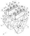
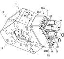
- FIG. 3A and 3B are diagrams illustrating a configuration of a power supply module according to the present embodiment, in which FIG. 3A is a plan view and FIG. 3B is a cross-sectional view taken along line III-III in FIG. 3A. It is a figure which shows the structure of the plate-shaped part which concerns on this embodiment, FIG. 4A is a perspective view, and FIG. 4B is a front view. It is a perspective view which shows the state which connected the male member and the female member of the electric power feeding module which concerns on this embodiment. It is a fragmentary longitudinal cross-section which shows the state which connected the male member and the female member of the electric power feeding module which concerns on embodiment.
- a tool changer 10 shown in FIG. 1 is fixed to a tool 14 and a male member 12 as a first connecting member fixed to a tip (not shown) of an arm as a main body of an industrial robot. And a female member 16 as a second connecting member.
- the male mold member 12 is accurately positioned with respect to the female mold member 16 by inserting a positioning pin 18 provided on the male mold body 17 into a positioning hole 20 formed in the female mold body 19 of the female mold member 16. Is done.
- the tool 14 is not particularly limited, but a spot welding gun is shown in the drawing.
- the male member 12 and the main body, and the female member 16 and the tool 14 are detachably fastened by a fastener (not shown) such as a bolt.
- the main body and the tool 14 can be connected and separated via the tool changer 10.
- the male member 12 and the female member 16 are provided with power supply modules 22A and 22B, respectively.
- the power supply modules 22A and 22B are provided with module main bodies 28A and 28B, contact portions 24A and 24B, and a lead-in portion 26.
- a power supply line (not shown) is drawn into the module main bodies 28A and 28B through the lead-in portion 26.
- the male member 12 and the female member 16 are connected to each other so that the contact portions 24 ⁇ / b> A and 24 ⁇ / b> B are electrically connected, and power can be supplied from the main body to the tool 14.
- the length of the module main bodies 28A and 28B in the direction connecting the male member 12 and the female member 16 is referred to as the thickness.
- a direction perpendicular to the thickness and parallel to the surface is called a longitudinal direction.
- the lead-in portion 26 is provided on one side surface of the module main bodies 28 ⁇ / b> A and 28 ⁇ / b> B, and includes a plate-like portion 32 and an outer peripheral holding portion 34.
- the pull-in portion 26 is formed so that the plurality of seal tubes 30 are fixed to one side surface of the module main bodies 28A and 28B and the outer periphery holding portion 34 can hold the outer periphery of the seal tube 30.
- the drawing-in part 26 is formed so that three seal pipes 30 can be fixed in a row in the longitudinal direction of one side surface of the module main bodies 28A and 28B.
- the power supply line is constituted by a three-core cable and divided into three single-core cables. A single core cable is inserted into the seal tube 30 one by one. As a result, the power supply line is drawn into the module main bodies 28A and 28B through the lead-in portion 26.
- the outer periphery holding part 34 has an annular part 35 having an arc shape and fastening parts 40 provided at both ends of the annular part 35.
- Two outer periphery holding portions 34 are used as a set.
- the annular portion 35 is brought into contact with the outer periphery of the seal tube 30, the fastening portions 40 are butted together so as to cover the outer periphery of the seal tube 30, and the fastening portion 40 is fastened with a fastening member, for example, a bolt. Hold the outer periphery of.
- the configuration of the module main bodies 28A and 28B will be described in detail with reference to FIGS. 3A and 3B. Note that the module main bodies 28A and 28B have the same main part configuration when applied to the male member 12 or the female member 16, and therefore only the module main body 28A applied to the male member 12 will be described.
- the module main body 28A has a container portion 33 in which a bottom portion 29 and a side portion 31 are integrally formed.
- the container 33 has an opening at the ceiling facing the bottom 29 and is closed by a flange 38.
- a drawing port 27 is formed on one side surface of the container portion 33, and the drawing portion 26 is fixed.
- the electrical connection part 43 is provided in the container part 33.
- the electrical connecting portion 43 is formed so as to be able to electrically connect the single core cable 36 drawn into the module main body 28A through the drawing portion 26 and the contact portion 24A.
- the electrical connection portion 43 includes a receiving portion 45 and a connecting portion 47 that electrically connects the receiving portion 45 and the contact portion 24A.
- One end of the contact portion 24 ⁇ / b> A is exposed from the bottom 29 of the container portion 33, and the other end is connected to the electrical connection portion 43.
- the single-core cable 36 has a conductive wire 37 covered with a covering portion 39.
- the seal tube 30 includes a tube portion 41 and a flange portion 42 that is integrally formed at the tip of the tube portion 41.
- the single core cable 36 is inserted from the proximal end of the seal tube 30 and drawn into the container portion 33.
- the outer periphery of the cylindrical portion 41 of the seal tube 30 is held by the outer periphery holding portion 34, whereby the sealing performance between the covering portion 39 and the inner peripheral surface of the seal tube 30 is maintained.
- the leading end of the conducting wire 37 is inserted into the receiving portion 45 and connected to the electrical connection portion 43 by crimping the receiving portion 45.
- the seal tube 30 is fixed in a state in which the flange portion 42 is sandwiched between the plate-like portion 32 and the one side surface of the module main body 28A so that the sealing property between the drawing-in portion 26 and the module main body 28A is maintained.
- the plate-like portion 32 has a cable insertion hole 48 and a positioning portion 50 formed on one surface of the plate-like portion 32.
- the plate-like portion 32 is formed in a size having substantially the same surface area as one side surface of the module main bodies 28A and 28B.
- the cable insertion holes 48 are through-holes opened in the thickness direction of the plate-like portion 32, and a plurality, three in the present embodiment, are formed in the longitudinal direction of the plate-like portion 32.
- the size of the cable insertion hole 48 is formed such that the seal tube 30 can be inserted.
- An annular groove 44 is formed on the other surface of the plate-like portion 32 concentrically with the cable insertion hole 48.
- the annular groove 44 is formed in a size that allows the flange portion 42 of the seal tube 30 to be sandwiched between the one side surfaces of the module main bodies 28A and 28B and seals between the drawing portion 26 and the module main bodies 28A and 28B. .
- the positioning portion 50 includes a protrusion 52 formed to protrude from one surface of the plate-like portion 32 and a through hole 54 formed in the protrusion 52. Two positioning portions 50 are formed for one cable insertion hole 48, that is, one for each side of the cable insertion hole 48.
- the protrusion 52 is formed such that the through hole 54 opens in the short direction of the plate-like portion 32.
- a pressing portion 55 is formed on the protruding portion 52 at a position facing the cable insertion hole 48.
- the holding portion 55 is formed of a flat surface and is formed so that the outer periphery of the seal tube 30 inserted into the cable insertion hole 48 can be pressed.
- the plate-like portion 32 is formed with a fixing member 56 for fixing the drawing portion 26 to the module main bodies 28A and 28B, for example, a fixing hole 56 for inserting a bolt.
- the fixing holes 56 are opened in the thickness direction of the plate-like portion 32, and in the present embodiment, two fixing holes 56 are arranged in addition to the four corners of the plate-like portion 32.
- the single-core cable 36 is inserted into the seal tube 30.
- the conducting wire 37 is connected to the electrical connection portion 43 at the tip portion.
- a set of outer periphery holding portions 34 are disposed on the outer periphery of the seal tube 30.
- the outer periphery holding part 34 makes the fastening parts 40 face each other with the projecting part 52 interposed therebetween, and inserts a fastening member from one fastening part 40 to the other fastening part 40 through the through hole 54 of the projecting part 52.
- the fastening member is fastened and fastened. Thereby, the space between the single-core cable 36 and the seal tube 30 is sealed.
- the lead-in portion 26 can be attached to the module main bodies 28A and 28B, and the power supply line can be drawn into the module main bodies 28A and 28B.
- the power supply modules 22A and 22B configured as described above are attached to the male member 12 and the female member 16, respectively. As shown in FIG. 5, the male member 12 and the female member 16 are connected to connect the industrial robot and the tool. When the male member 12 and the female member 16 are coupled, the contact portions 24A and 24B are electrically connected to each other as shown in FIG. Accordingly, power is supplied to the tool 14 from the main body through the power supply modules 22A and 22B through the single-core cable 36.
- the lead-in portion 26 divides the three-core cable into three single-core cables 36, and the single-core cables 36 are arranged in a line in the longitudinal direction of one side surface of the module main bodies 28A and 28B.
- the thickness of the module main bodies 28A and 28B can be reduced. Therefore, the power supply modules 22A and 22B can be reduced in size.
- the projecting portion 52 is formed so that the through hole 54 opens in the short direction of the plate-like portion 32, so that a fastening member for fastening the pair of outer peripheral holding portions 34 is used as the thickness of the module main bodies 28 ⁇ / b> A and 28 ⁇ / b> B. Can be inserted from the direction. Therefore, the power supply modules 22A and 22B can easily tighten the fastening member without interference of the fastening tool for fastening the fastening member with the protrusions 52 and the single-core cable 36, thereby improving workability. Can do. Further, since the protrusion 52 is formed integrally with the plate-like portion 32, the position of the fastening member can be maintained even if the single-core cable 36 is bent.
- the pull-in portion 26 holds a fixed region on the outer periphery of the seal tube 30 with respect to the plate-like portion 32 by a pair of outer periphery holding portions 34 and a presser portion 55 formed on the protrusion 52. Thereby, even if the other end side of the single-core cable 36 in which the tip was drawn is bent, the sealing performance by the seal tube 30 can be maintained.
- the retracting portion 26 according to the present embodiment can be curved in the longitudinal direction, the degree of freedom in design can be improved.
- the retracting portion 26 is configured so that the seal tube 30 generates a clamping force, the configuration can be simplified.
- the lead-in portion 26 has been described with respect to the case where the three single-core cables 36 are configured to be arranged in a line in the longitudinal direction of the one side surface of the module main bodies 28A and 28B.
- the present invention is not limited to this, and it may be configured such that four or more single-core cables 36 can be arranged.
- the outer peripheral holding part 34 has the annular part 35 and the fastening parts 40 provided at both ends of the annular part 35, and the case where two are used as one set has been described. Not only this but one fastening part 40 may be integrated, and it is good also as a C-shaped one member as a whole. In this case, one positioning part 50 can be provided for one cable insertion hole 48.
- the power supply modules 22A and 22B have been described with respect to the case where the power supply is transmitted via a cable.
- the present invention is not limited to this and is applied to the case where an electrical signal is transmitted via a signal cable. You can also.
- a device to which a tool changer including a power supply module is attached is not limited to an industrial robot.
- it may be a balance arm or a hand crane that facilitates movement of a tool attached to the arm, or an object gripped by the tool and work at the movement destination.
- the first connecting member is attached to the arm of the industrial robot on the main body side of the device, but the mounting position is determined at an arbitrary position on the main body of the device depending on the configuration of the device and the type of tool. Can do.
- Tool changer 12 Male member (first connecting member) 14 Tool 16 Female member (second connecting member) 22A, 22B Power supply module 26 Pull-in portion 28A, 28B Module body 30 Seal tube 32 Plate-like portion 34 Outer peripheral holding portion 42 Flange portion 48 Cable insertion hole 52 Projection portion 54 Through hole
Landscapes
- Engineering & Computer Science (AREA)
- Robotics (AREA)
- Mechanical Engineering (AREA)
- Manipulator (AREA)
- Laying Of Electric Cables Or Lines Outside (AREA)
Abstract
モジュール本体(28A,28B)と、前記モジュール本体(28A,28B)の一側表面に設けられた引き込み部(26)とを備え、前記引き込み部(26)は、前記モジュール本体(28A,28B)の一側表面にシール管(30)を固定する板状部(32)と、前記シール管(30)の外周を保持する外周保持部(34)とを有し、前記板状部(32)は、複数の、ケーブル挿入穴と、前記ケーブル挿入穴に対し前記外周保持部(34)を位置決めする位置決め部(50)とが、前記モジュール本体(28A,28B)の一側表面の長手方向に設けられていることを特徴とする、小型化することができる給電モジュールを提供する。
Description
本発明は、給電モジュールに関し、特に工具交換装置に適用されるものに関する。
各種機器、例えば産業用ロボットに適用される工具交換装置として、ロボット側に取り付けられる雄型部材と、工具側に取り付けられる雌型部材を備えるものが開示されている(例えば、特許文献1)。工具交換装置は、用途に応じてロボットから工具へケーブルを介して電源電力や電気信号を伝送するための給電モジュールが取り付けられる。給電モジュールは、雄型部材及び雌型部材に取り付けられ、雄型部材と雌型部材を連結したときに電気的に接続される接点部と、外部のケーブルを繋ぐコネクタ部とを有する。
しかしながら従来の給電モジュールの場合、例えば電源電力を伝送するには、コネクタ部が、3芯ケーブル用のコネクタを用いることが多く、大型化せざるを得ない、という問題がある。特に、給電モジュールの厚さは、コネクタ部の大きさによって制約され、小型化することができない。
そこで本発明は、小型化することができる給電モジュールを提供することを目的とする。
本発明に係る給電モジュールは、機器の本体側に着脱自在に取り付けられる第1連結部材と、工具側に着脱自在に取り付けられる第2連結部材とを備える工具交換装置の、前記第1連結部材又は前記第2連結部材に着脱自在に取り付けられる給電モジュールにおいて、モジュール本体と、前記モジュール本体の一側表面に設けられた引き込み部とを備え、前記引き込み部は、前記モジュール本体の一側表面にシール管を固定する板状部と、前記シール管の外周を保持する外周保持部とを有し、前記板状部は、複数の、ケーブル挿入穴と、前記ケーブル挿入穴に対し前記外周保持部を位置決めする位置決め部とが、前記モジュール本体の一側表面の長手方向に設けられていることを特徴とする。
本発明によれば、引き込み部は、ケーブルをモジュール本体の一側表面の長手方向に配置することができるので、モジュール本体の厚さを小さくすることができる。したがって給電モジュールは、小型化することができる。
以下、図面を参照して本発明の実施形態について詳細に説明する。
(1)全体構成
図1に示す工具交換装置10は、産業用ロボットの本体としてのアームの先端(図示しない)に固定される第1連結部材としての雄型部材12と、工具14に固定される第2連結部材としての雌型部材16とを備える。雄型部材12は、雄型本体17に設けられた位置決めピン18を、雌型部材16の雌型本体19に形成された位置決め穴20に挿入することにより、雌型部材16に対し正確に位置決めされる。工具14は特に限定されないが、本図においてはスポット溶接ガンが図示されている。雄型部材12と本体、及び雌型部材16と工具14は、図示しない締結具、例えばボルトにより、着脱自在に締結される。本体と工具14は、工具交換装置10を介して、連結されると共に、分離し得る。
図1に示す工具交換装置10は、産業用ロボットの本体としてのアームの先端(図示しない)に固定される第1連結部材としての雄型部材12と、工具14に固定される第2連結部材としての雌型部材16とを備える。雄型部材12は、雄型本体17に設けられた位置決めピン18を、雌型部材16の雌型本体19に形成された位置決め穴20に挿入することにより、雌型部材16に対し正確に位置決めされる。工具14は特に限定されないが、本図においてはスポット溶接ガンが図示されている。雄型部材12と本体、及び雌型部材16と工具14は、図示しない締結具、例えばボルトにより、着脱自在に締結される。本体と工具14は、工具交換装置10を介して、連結されると共に、分離し得る。
雄型部材12及び雌型部材16には、それぞれ給電モジュール22A、22Bが取り付けられている。給電モジュール22A、22Bは、モジュール本体28A、28Bと、接点部24A、24Bと、引き込み部26とが設けられている。引き込み部26を通じて電源供給線(図示しない)がモジュール本体28A、28B内に引き込まれる。工具交換装置10は、雄型部材12と雌型部材16が連結されることにより、接点部24A、24Bが電気的に接続され、本体から工具14へ電源電力が供給され得る。なお、以下の説明において、雄型部材12と雌型部材16を連結する方向のモジュール本体28A、28Bの長さを厚さという。また厚さに直交し、表面に平行な方向を長手方向という。
図2に示すように、引き込み部26は、モジュール本体28A、28Bの一側表面に設けられており、板状部32と、外周保持部34とを有する。引き込み部26は、複数のシール管30をモジュール本体28A、28Bの一側表面に固定すると共に、外周保持部34によってシール管30の外周を保持し得るように形成されている。本実施形態の場合、引き込み部26は、シール管30をモジュール本体28A、28Bの一側表面の長手方向に、一列に3個固定し得るように形成されている。本図には図示しないが、電源供給線は、3芯ケーブルで構成され、3本の単芯ケーブルに分割される。シール管30には、単芯ケーブルが1本ずつ挿入される。これにより電源供給線は、引き込み部26を通じてモジュール本体28A、28B内に引き込まれる。
外周保持部34は、円弧形状からなる環状部35と、環状部35の両端に設けられた締結部40とを有する。外周保持部34は、2個を一組として使用される。環状部35をシール管30の外周に接触させ、シール管30の外周を覆うようにして、締結部40同士を突き合わせ、当該締結部40を締結部材、例えばボルトにより締結することにより、シール管30の外周を保持する。
図3A,Bを参照してモジュール本体28A、28Bの構成を詳しく説明する。なお、モジュール本体28A、28Bは、雄型部材12又は雌型部材16に適用する場合において、主要部の構成が共通するため、雄型部材12に適用されるモジュール本体28Aについてのみ説明する。モジュール本体28Aは、底部29と側部31とが一体に形成された容器部33を有する。容器部33は、底部29に対向する天井部分は開口が形成されており、フランジ38で閉塞されている。容器部33の一側表面には、引き込み口27が形成されており、引き込み部26が固定されている。
容器部33内には、電気的接続部43が設けられている。電気的接続部43は、引き込み部26を通じてモジュール本体28A内に引き込まれた単芯ケーブル36と接点部24Aとを電気的に接続し得るように形成されている。電気的接続部43は、受容部45と、当該受容部45と接点部24Aとを電気的に接続する連結部47とを有する。接点部24Aは、一端が容器部33の底部29から露出していると共に、他端が電気的接続部43に接続されている。
単芯ケーブル36は、導線37が被覆部39に覆われている。シール管30は、筒部41と、当該筒部41の先端に一体に形成されたフランジ部42とを有する。単芯ケーブル36は、シール管30の基端から挿入され、容器部33内に引き込まれている。単芯ケーブル36は、シール管30の筒部41の外周が外周保持部34で保持されることにより、被覆部39とシール管30内周面の間のシール性が保たれる。導線37の先端は、受容部45に挿入され、当該受容部45を加締めることにより、電気的接続部43に接続される。シール管30は、フランジ部42が、板状部32とモジュール本体28Aの一側表面との間に挟まれることにより、引き込み部26とモジュール本体28Aの間のシール性を保った状態で固定される。
図4A,Bに示すように、板状部32は、ケーブル挿入穴48と、板状部32の一側表面に形成された位置決め部50とを有する。板状部32は、モジュール本体28A、28Bの一側表面と略同じ表面積を有する大きさに形成されている。ケーブル挿入穴48は、板状部32の厚さ方向に開口した貫通穴であり、板状部32の長手方向に複数、本実施形態の場合、3個均等に形成されている。ケーブル挿入穴48の大きさは、シール管30を挿入し得る大きさに形成されている。板状部32の他側表面には、ケーブル挿入穴48と同心円状に環状溝44が形成されている。環状溝44は、シール管30のフランジ部42を、モジュール本体28A、28Bの一側表面との間に挟み、引き込み部26とモジュール本体28A、28Bの間をシールし得る大きさに形成される。
位置決め部50は、板状部32の一側表面から突出して形成された突起部52と、当該突起部52に形成された貫通穴54とを有する。位置決め部50は、1個のケーブル挿入穴48に対し2個、すなわち1個のケーブル挿入穴48を挟んで両側に1個ずつ形成されている。突起部52は、貫通穴54が板状部32の短手方向に開口するように形成されている。突起部52には、ケーブル挿入穴48に面した位置に押え部55が形成されている。押え部55は、平坦な面で構成され、ケーブル挿入穴48に挿入されたシール管30の外周を押え得るように形成されている。
板状部32には、モジュール本体28A、28Bに引き込み部26を固定する締結部材、例えばボルトを挿入する固定穴56が適所に形成されている。固定穴56は、板状部32の厚さ方向に開口しており、本実施形態の場合、板状部32の四隅に加え、2個配置されている。
(2)作用及び効果
上記のように構成された給電モジュール22A、22Bの作用及び効果について説明する。まず、引き込み部26をモジュール本体28A、28Bに取り付ける手順を説明する。最初に引き込み部26の板状部32にシール管30を、フランジ部42が板状部32の他側表面に形成された環状溝44に装填されるように挿入する。次いで、シール管30が挿入された板状部32を、モジュール本体28A、28Bの一側表面に固定する。板状部32とモジュール本体28A、28Bの間は、シール管30のフランジ部42により、シールされる。
上記のように構成された給電モジュール22A、22Bの作用及び効果について説明する。まず、引き込み部26をモジュール本体28A、28Bに取り付ける手順を説明する。最初に引き込み部26の板状部32にシール管30を、フランジ部42が板状部32の他側表面に形成された環状溝44に装填されるように挿入する。次いで、シール管30が挿入された板状部32を、モジュール本体28A、28Bの一側表面に固定する。板状部32とモジュール本体28A、28Bの間は、シール管30のフランジ部42により、シールされる。
次いで、シール管30に単芯ケーブル36を挿入する。単芯ケーブル36は、先端部分において導線37が電気的接続部43に接続される。単芯ケーブル36が挿入された状態において、シール管30の外周に、一組の外周保持部34を配置する。外周保持部34は、締結部40同士を、突起部52を挟んで対向させ、一方の締結部40から突起部52の貫通穴54を介して他方の締結部40へ向かって締結部材を挿入し、当該締結部材を締めつけて締結される。これにより、単芯ケーブル36とシール管30の間がシールされる。このようにして引き込み部26をモジュール本体28A、28Bに取り付けると共に、電源供給線をモジュール本体28A、28Bに引き込むことができる。
このように構成された給電モジュール22A、22Bは、それぞれ雄型部材12及び雌型部材16に取り付けられる。雄型部材12と雌型部材16は、図5に示すように、連結することにより、産業ロボットと工具とを連結する。そして雄型部材12と雌型部材16が連結されると、図6に示すように、接点部24A、24B同士が電気的に接続される。これにより、単芯ケーブル36を通じて本体から給電モジュール22A、22Bを介して工具14へ電源電力が供給される。
本実施形態の場合、引き込み部26は、3芯ケーブルを3本の単芯ケーブル36に分割し、当該単芯ケーブル36をモジュール本体28A、28Bの一側表面の長手方向に一列に配置したことにより、モジュール本体28A、28Bの厚さを小さくすることができる。したがって給電モジュール22A、22Bは、小型化することができる。
突起部52は、貫通穴54が板状部32の短手方向に開口するように形成されていることにより、一組の外周保持部34を締め付ける締結部材を、モジュール本体28A、28Bの厚さ方向から挿入することができる。したがって、給電モジュール22A、22Bは、締結部材を締めつける締め付け工具が互いの突起部52や単芯ケーブル36に干渉することがなく、容易に締結部材を締めつけることができるので、作業性を向上することができる。また突起部52は、板状部32に一体に形成されていることにより、単芯ケーブル36が曲げられたりしても、締結部材の位置を保持することができる。
引き込み部26は、一組の外周保持部34と、突起部52に形成された押え部55とにより、シール管30の外周の一定領域を板状部32に対し保持している。これにより、先端が引き込まれた単芯ケーブル36の他端側が曲げられても、シール管30によるシール性を保持することができる。
さらに本実施形態に係る引き込み部26は、長手方向に湾曲させることもできるので、設計の自由度を向上することができる。
また引き込み部26は、シール管30がクランプ力を生じるように構成したので、構成を簡略化することができる。
(3)変形例
本発明は上記実施形態に限定されるものではなく、本発明の趣旨の範囲内で適宜変更することが可能である。
本発明は上記実施形態に限定されるものではなく、本発明の趣旨の範囲内で適宜変更することが可能である。
上記実施形態の場合、引き込み部26は、3本の単芯ケーブル36をモジュール本体28A、28Bの一側表面の長手方向に一列に配置し得るように構成した場合について説明したが、本発明はこれに限らず、4本以上の単芯ケーブル36を配置し得るように構成してもよい。
上記実施形態の場合、外周保持部34は、環状部35と、環状部35の両端に設けられた締結部40とを有し、2個を一組として用いる場合について説明したが、本発明はこれに限らず、一方の締結部40同士を一体化して、全体としてC型形状の1つの部材としてもよい。この場合、位置決め部50は、1個のケーブル挿入穴48に対し1個とすることができる。
上記実施形態の場合、給電モジュール22A、22Bは、ケーブルを介して電源電力を伝送する場合について説明したが、本発明はこれに限らず、信号ケーブルを介して電気信号を伝送する場合に適用することもできる。
上記実施形態では、機器の一例として産業ロボットの場合を説明したが、給電モジュールを含め工具交換装置を取り付ける機器は、産業用ロボットに限定されるものではない。例えばアームに取付けられた工具、あるいはその工具で把持した物の移動や移動先での作業を容易にするバランスアームやハンドクレーンなどであってもよい。また、機器の本体側である産業ロボットのアームに第1連結部材を取り付けているが、その取り付け位置は、機器の構成や工具の種類などに応じて、機器の本体の任意の位置に決めることができる。
10 工具交換装置
12 雄型部材(第1連結部材)
14 工具
16 雌型部材(第2連結部材)
22A、22B 給電モジュール
26 引き込み部
28A、28B モジュール本体
30 シール管
32 板状部
34 外周保持部
42 フランジ部
48 ケーブル挿入穴
52 突起部
54 貫通穴
12 雄型部材(第1連結部材)
14 工具
16 雌型部材(第2連結部材)
22A、22B 給電モジュール
26 引き込み部
28A、28B モジュール本体
30 シール管
32 板状部
34 外周保持部
42 フランジ部
48 ケーブル挿入穴
52 突起部
54 貫通穴
Claims (4)
- 機器の本体側に着脱自在に取り付けられる第1連結部材と、工具側に着脱自在に取り付けられる第2連結部材とを備える工具交換装置の、前記第1連結部材又は前記第2連結部材に着脱自在に取り付けられる給電モジュールにおいて、
モジュール本体と、
前記モジュール本体の一側表面に設けられた引き込み部と
を備え、
前記引き込み部は、
前記モジュール本体の一側表面にシール管を固定する板状部と、
前記シール管の外周を保持する外周保持部と
を有し、
前記板状部は、複数の、ケーブル挿入穴と、前記ケーブル挿入穴に対し前記外周保持部を位置決めする位置決め部とが、前記モジュール本体の一側表面の長手方向に設けられていることを特徴とする給電モジュール。 - 前記位置決め部は、
前記板状部の一側表面から突出して形成された突起部と、
前記突起部に形成され、前記突起部を挟んで2個を1組とする前記外周保持部を突き合せた状態で、当該外周保持部に締結部材を挿入するための貫通穴と
を有することを特徴とする請求項1記載の給電モジュール。 - 前記貫通穴は、前記板状部の短手方向に開口していることを特徴とする請求項2記載の給電モジュール。
- 前記板状部の他側表面には、前記シール管の先端に形成されたフランジ部を装填する環状溝が形成されていることを特徴とする請求項1~3のいずれか1項記載の給電モジュール。
Priority Applications (2)
| Application Number | Priority Date | Filing Date | Title |
|---|---|---|---|
| CN201580061478.8A CN107428013B (zh) | 2014-12-26 | 2015-12-09 | 供电组件 |
| US15/535,866 US9925673B2 (en) | 2014-12-26 | 2015-12-09 | Power supplying module |
Applications Claiming Priority (2)
| Application Number | Priority Date | Filing Date | Title |
|---|---|---|---|
| JP2014-264305 | 2014-12-26 | ||
| JP2014264305A JP6454543B2 (ja) | 2014-12-26 | 2014-12-26 | 給電モジュール |
Publications (1)
| Publication Number | Publication Date |
|---|---|
| WO2016104150A1 true WO2016104150A1 (ja) | 2016-06-30 |
Family
ID=56150180
Family Applications (1)
| Application Number | Title | Priority Date | Filing Date |
|---|---|---|---|
| PCT/JP2015/084531 Ceased WO2016104150A1 (ja) | 2014-12-26 | 2015-12-09 | 給電モジュール |
Country Status (4)
| Country | Link |
|---|---|
| US (1) | US9925673B2 (ja) |
| JP (1) | JP6454543B2 (ja) |
| CN (1) | CN107428013B (ja) |
| WO (1) | WO2016104150A1 (ja) |
Families Citing this family (2)
| Publication number | Priority date | Publication date | Assignee | Title |
|---|---|---|---|---|
| CN107359463A (zh) * | 2016-12-06 | 2017-11-17 | 中日龙(襄阳)机电技术开发有限公司 | 一种防水及防尘非接触连接器 |
| WO2019114893A1 (en) | 2017-12-14 | 2019-06-20 | Onrobot A/S | Gripping device |
Citations (4)
| Publication number | Priority date | Publication date | Assignee | Title |
|---|---|---|---|---|
| JPS6330183A (ja) * | 1986-07-16 | 1988-02-08 | コマウ・ソチエタ・ペル・アチオニ | 産業用ロボツト用自動式工具交換装置 |
| JPH06190760A (ja) * | 1993-04-01 | 1994-07-12 | Applied Robotics Inc | 自動工具交換装置用の結合装置 |
| JP2001035567A (ja) * | 1999-07-27 | 2001-02-09 | Jst Mfg Co Ltd | 同軸ケーブルのグランド処理装置 |
| JP2001332320A (ja) * | 2000-05-25 | 2001-11-30 | Smk Corp | 同軸コネクタ |
Family Cites Families (18)
| Publication number | Priority date | Publication date | Assignee | Title |
|---|---|---|---|---|
| FR2612109B3 (fr) * | 1987-03-11 | 1989-10-06 | Renault Automation Sa | Dispositif de changement d'outil de robot |
| JPH0753352B2 (ja) * | 1990-10-29 | 1995-06-07 | ニッタ株式会社 | 自動工具交換用カップラー |
| JPH07223187A (ja) * | 1994-02-09 | 1995-08-22 | Matsushita Electric Ind Co Ltd | 自動着脱回転式ツールヘッド |
| US6116966A (en) * | 1998-04-17 | 2000-09-12 | Ati Industrial Automation, Inc. | High power electrical contacts for robotic tool changer |
| US6979779B2 (en) * | 2001-11-21 | 2005-12-27 | Grady John K | Square electrical outlet box with exterior clamp shelves for holding electrical cables |
| JP2008207294A (ja) * | 2007-02-27 | 2008-09-11 | Kondo Seisakusho:Kk | 自動工具交換装置 |
| US9254572B2 (en) * | 2009-02-04 | 2016-02-09 | Ati Industrial Automation, Inc. | Power control of a robotic tool changer |
| US8035029B2 (en) * | 2009-05-21 | 2011-10-11 | G.A Fleet Associates, Inc. | Environmentally-isolated electrical junction box and method of installing and servicing the same |
| CN101890724B (zh) * | 2010-07-02 | 2011-11-30 | 上海理工大学 | 群机器人模块标准快换接口 |
| CN201937110U (zh) * | 2011-01-13 | 2011-08-17 | 杭州日月电器股份有限公司 | 电连接器弯式尾罩防护结构 |
| DE202011000150U1 (de) * | 2011-01-21 | 2012-05-02 | Kuka Systems Gmbh | Wechselkupplung |
| JP5697549B2 (ja) | 2011-06-03 | 2015-04-08 | ニッタ株式会社 | 自動工具交換装置 |
| FI9822U1 (fi) * | 2011-06-28 | 2012-09-28 | Vacon Oyj | Sähkökaapelin liitäntäjärjestely |
| TWM419290U (en) * | 2011-07-28 | 2011-12-21 | Hon Hai Prec Ind Co Ltd | Waterproof structure for connector |
| KR200474883Y1 (ko) * | 2012-09-05 | 2014-10-22 | 엘에스산전 주식회사 | 전기 자동차 충전기 |
| CA2807452A1 (en) * | 2012-10-26 | 2014-04-26 | Asahi Denshi Co., Ltd. | Cable bushing |
| CN203288858U (zh) * | 2013-05-27 | 2013-11-13 | 浙江中欣动力测控技术有限公司 | 一种用于测量滑油屑末的在线传感器的线缆接头 |
| CN103682795A (zh) * | 2013-11-25 | 2014-03-26 | 泰兴市航天电器有限公司 | 一种圆形电连接器用防水尾夹 |
-
2014
- 2014-12-26 JP JP2014264305A patent/JP6454543B2/ja active Active
-
2015
- 2015-12-09 CN CN201580061478.8A patent/CN107428013B/zh active Active
- 2015-12-09 WO PCT/JP2015/084531 patent/WO2016104150A1/ja not_active Ceased
- 2015-12-09 US US15/535,866 patent/US9925673B2/en active Active
Patent Citations (4)
| Publication number | Priority date | Publication date | Assignee | Title |
|---|---|---|---|---|
| JPS6330183A (ja) * | 1986-07-16 | 1988-02-08 | コマウ・ソチエタ・ペル・アチオニ | 産業用ロボツト用自動式工具交換装置 |
| JPH06190760A (ja) * | 1993-04-01 | 1994-07-12 | Applied Robotics Inc | 自動工具交換装置用の結合装置 |
| JP2001035567A (ja) * | 1999-07-27 | 2001-02-09 | Jst Mfg Co Ltd | 同軸ケーブルのグランド処理装置 |
| JP2001332320A (ja) * | 2000-05-25 | 2001-11-30 | Smk Corp | 同軸コネクタ |
Also Published As
| Publication number | Publication date |
|---|---|
| JP6454543B2 (ja) | 2019-01-16 |
| CN107428013B (zh) | 2021-02-09 |
| US20170348861A1 (en) | 2017-12-07 |
| JP2016124040A (ja) | 2016-07-11 |
| US9925673B2 (en) | 2018-03-27 |
| CN107428013A (zh) | 2017-12-01 |
Similar Documents
| Publication | Publication Date | Title |
|---|---|---|
| US10153584B2 (en) | Connector with electroconductive member featuring retraction mechanism | |
| US10734750B2 (en) | Closing-body holding structure and electric wire with connector | |
| US10490922B2 (en) | Flat electric cable connection structure | |
| US11223157B2 (en) | Fitting connector | |
| US20240372304A1 (en) | Connector | |
| JP2007123024A (ja) | 端子可動コネクタ | |
| JP2021034153A5 (ja) | コネクタ用シール構造及びコネクタ | |
| WO2019176663A1 (ja) | コネクタ | |
| CN111384702B (zh) | 线缆固定装置、线缆连接器和电器设备 | |
| WO2019181141A1 (ja) | 組付補助部品付配線体、配線体の組付補助部品及び配線体組付物の製造方法 | |
| US8056867B2 (en) | Position assurance assembly for an electrical connector | |
| JP2018513535A (ja) | 電気差込コネクタ部品 | |
| JP6454543B2 (ja) | 給電モジュール | |
| US10974384B2 (en) | Force detecting device and robot system | |
| JP5255492B2 (ja) | コネクタ | |
| JP2015085449A (ja) | ロボット | |
| KR102463691B1 (ko) | 커넥터 | |
| JP2021036740A (ja) | 複合ケーブル用中継装置 | |
| JP2022061147A (ja) | 端子台 | |
| US10319976B2 (en) | Cable fixing structure | |
| JP5766529B2 (ja) | フラットケーブルの防水コネクタ構造 | |
| JP5078699B2 (ja) | 電源端子保護カバー | |
| JP2018206638A (ja) | バスバーモジュール | |
| JP2009004179A (ja) | 電線ホルダ | |
| JP2024022819A (ja) | クランプ |
Legal Events
| Date | Code | Title | Description |
|---|---|---|---|
| 121 | Ep: the epo has been informed by wipo that ep was designated in this application |
Ref document number: 15872719 Country of ref document: EP Kind code of ref document: A1 |
|
| WWE | Wipo information: entry into national phase |
Ref document number: 15535866 Country of ref document: US |
|
| NENP | Non-entry into the national phase |
Ref country code: DE |
|
| 122 | Ep: pct application non-entry in european phase |
Ref document number: 15872719 Country of ref document: EP Kind code of ref document: A1 |