WO2016104107A1 - ホットプレス用成形型装置及び保護部材付電線の製造方法 - Google Patents
ホットプレス用成形型装置及び保護部材付電線の製造方法 Download PDFInfo
- Publication number
- WO2016104107A1 WO2016104107A1 PCT/JP2015/084115 JP2015084115W WO2016104107A1 WO 2016104107 A1 WO2016104107 A1 WO 2016104107A1 JP 2015084115 W JP2015084115 W JP 2015084115W WO 2016104107 A1 WO2016104107 A1 WO 2016104107A1
- Authority
- WO
- WIPO (PCT)
- Prior art keywords
- mold
- lower mold
- support shaft
- upper mold
- electric wire
- Prior art date
- Legal status (The legal status is an assumption and is not a legal conclusion. Google has not performed a legal analysis and makes no representation as to the accuracy of the status listed.)
- Ceased
Links
Images




Classifications
-
- B—PERFORMING OPERATIONS; TRANSPORTING
- B29—WORKING OF PLASTICS; WORKING OF SUBSTANCES IN A PLASTIC STATE IN GENERAL
- B29C—SHAPING OR JOINING OF PLASTICS; SHAPING OF MATERIAL IN A PLASTIC STATE, NOT OTHERWISE PROVIDED FOR; AFTER-TREATMENT OF THE SHAPED PRODUCTS, e.g. REPAIRING
- B29C43/00—Compression moulding, i.e. applying external pressure to flow the moulding material; Apparatus therefor
- B29C43/32—Component parts, details or accessories; Auxiliary operations
- B29C43/36—Moulds for making articles of definite length, i.e. discrete articles
-
- B—PERFORMING OPERATIONS; TRANSPORTING
- B29—WORKING OF PLASTICS; WORKING OF SUBSTANCES IN A PLASTIC STATE IN GENERAL
- B29C—SHAPING OR JOINING OF PLASTICS; SHAPING OF MATERIAL IN A PLASTIC STATE, NOT OTHERWISE PROVIDED FOR; AFTER-TREATMENT OF THE SHAPED PRODUCTS, e.g. REPAIRING
- B29C43/00—Compression moulding, i.e. applying external pressure to flow the moulding material; Apparatus therefor
- B29C43/32—Component parts, details or accessories; Auxiliary operations
- B29C43/50—Removing moulded articles
-
- H—ELECTRICITY
- H01—ELECTRIC ELEMENTS
- H01B—CABLES; CONDUCTORS; INSULATORS; SELECTION OF MATERIALS FOR THEIR CONDUCTIVE, INSULATING OR DIELECTRIC PROPERTIES
- H01B13/00—Apparatus or processes specially adapted for manufacturing conductors or cables
- H01B13/012—Apparatus or processes specially adapted for manufacturing conductors or cables for manufacturing wire harnesses
-
- H—ELECTRICITY
- H02—GENERATION; CONVERSION OR DISTRIBUTION OF ELECTRIC POWER
- H02G—INSTALLATION OF ELECTRIC CABLES OR LINES, OR OF COMBINED OPTICAL AND ELECTRIC CABLES OR LINES
- H02G3/00—Installations of electric cables or lines or protective tubing therefor in or on buildings, equivalent structures or vehicles
- H02G3/02—Details
- H02G3/04—Protective tubing or conduits, e.g. cable ladders or cable troughs
Definitions
- This invention relates to a technique for forming a protective member formed of a non-woven member around an electric wire.
- Patent Document 1 discloses a mold that heats and pressurizes a nonwoven fabric wound around an electric wire.
- the mold includes a first mold and a second mold.
- the first mold has a groove-like structure, and the second mold has a protruding structure.
- the nonwoven fabric wound by the electric wire is arrange
- the non-woven fabric may stick to the mold surface, or the non-woven fabric may be clogged between the first mold and the second mold. In these cases, it becomes difficult to remove the second mold from the first mold.
- the first molding die is provided so that the screw can be screwed, and the tip of the screw that moves by being screwed in the tightening direction is brought into contact with the second molding die. It is conceivable that the second mold is floated with respect to the mold so that the second mold can be easily removed from the first mold.
- an object of the present invention is to make it possible to easily remove an upper mold from a lower mold in a hot pressing mold apparatus for hot pressing a nonwoven fabric.
- a first aspect is a hot pressing mold apparatus for hot pressing a non-woven member covering an electric wire, and a groove in which the non-woven member covering the electric wire and the electric wire can be disposed
- An upper mold surface for compressing the nonwoven member covering the electric wire between the lower mold surface and the lower mold surface in a state where the lower mold surface is combined with the lower mold surface.
- a lever member is provided that includes an operation portion provided at a position away from the shaft and an action portion provided at a position where the distance to the support shaft is smaller than the distance between the support shaft and the operation portion.
- the lower die and the upper die are combined with the other of the lower die and the upper die.
- a 2nd aspect is a shaping apparatus for hot presses which concerns on a 1st aspect, Comprising: The said lever member and the said receiving part are provided in the position from the edge part of the said lower mold
- a 3rd aspect is a shaping apparatus for hot presses which concerns on the 1st or 2nd aspect, Comprising: In the said lever member, the said action part is provided between the said spindle and the said operation part. It is.
- a fourth aspect is a hot press mold apparatus according to the third aspect, wherein the action portion is the other of the lower die and the upper die with respect to a line connecting the support shaft and the operation portion. And curved so as to be convex toward the side, and has a curved surface that sequentially approaches a line connecting the support shaft and the operation portion from the support shaft side toward the operation portion, and as the lever member is rotated The receiving portion is in contact with the curved surface while moving from a portion close to the support shaft side toward a portion close to the operation portion side.
- a fifth aspect is a method of manufacturing an electric wire with a protective member using the hot pressing mold device according to any one of the first to fourth aspects, wherein (a) the electric wire and the electric wire covering the electric wire are not covered.
- the hot press mold apparatus when the operator operates the operating portion to rotate the lever member around the support shaft, the acting portion comes into contact with the receiving portion, and the lower die and the upper die Move the mold relative to the separation direction. At this time, since the distance between the support shaft and the action portion is smaller than the distance between the support shaft and the operation portion, the operator may operate the operation portion with a relatively light force. And if the lower mold and the upper mold are relatively moved in the separation direction, the nonwoven member stuck on the upper mold surface or the lower mold surface is peeled off, or the non-woven member clogged between the lower mold and the upper mold is removed. Get out of between them. For this reason, in the hot pressing mold apparatus for hot pressing the nonwoven fabric, the upper mold can be easily removed from the lower mold.
- the non-woven member attached to the upper mold surface or the lower mold surface is peeled off sequentially from the ends of the lower mold and the upper mold, or the non-woven member packed in the lower mold and the upper mold is The lower mold and the upper mold are sequentially removed from the ends thereof. For this reason, in the hot pressing mold apparatus for hot pressing the nonwoven fabric, the upper mold can be more easily removed from the lower mold.
- the lever member since the action portion is provided between the support shaft and the operation portion, the lever member can be made compact.
- the action portion is curved so as to protrude toward the other side of the lower die and the upper die with respect to a line connecting the support shaft and the operation portion, and the support A curved surface that gradually approaches a line connecting the support shaft and the operation portion as it goes from the shaft side to the operation portion, and as the lever member is rotated, the receiving portion moves toward the support shaft side of the curved surface.
- the lever member can be operated smoothly and the lower mold and the upper mold can be moved smoothly and relatively apart from each other while moving from a close portion toward a portion close to the operation portion side. it can. Moreover, the damage in the part which contacts the curved surface of an action part among receiving parts can be suppressed.
- the electric wire with a protective member can be manufactured easily and efficiently.
- FIG. 5 is a cross-sectional view taken along line VV in FIG. 4. It is a side view which shows a lever member and a receiving part. It is a top view which shows a lever member. It is explanatory drawing which shows operation
- FIG. 1 is a perspective view showing a protective member-attached electric wire 10 to be manufactured.
- the protective member-equipped electric wire 10 includes at least one electric wire 11 and a protective member 14.
- the plurality of electric wires 11 may be branched in the middle of the extending direction of the protective member 14 or outside.
- An optical fiber cable may be bundled together with respect to at least one electric wire 11.
- a terminal is attached to the end of the electric wire 11, and the terminal is assembled into a connector.
- the connector 10 is connected to the connector on the various electric equipment side mounted in the vehicle etc. in the state where this electric wire 10 with a protection member is arrange
- this electric wire 10 with a protection member is used as wiring which electrically connects the various electric devices mounted in the vehicle etc.
- the protective member 14 is formed by hot pressing in a state where the non-woven member covers at least a part (here, a part) of the intermediate part in the longitudinal direction of the plurality of electric wires 11.
- the non-woven member a non-woven material that is hardened through the heating and pressurizing steps and can be joined to each other is used.
- a nonwoven material a material containing intertwined basic fibers and an adhesive resin (also called a binder) can be used.
- the adhesive resin is a resin having a melting point lower than the melting point of the basic fiber. Then, by heating the nonwoven material to a processing temperature lower than the melting point of the basic fiber and higher than the melting point of the adhesive resin, the adhesive resin melts and soaks between the basic fibers. Thereafter, when the non-woven material reaches a temperature lower than the melting point of the adhesive resin, the adhesive resin is solidified in a state where the basic fibers are bonded to each other. As a result, the nonwoven material becomes harder than the state before heating and is maintained in the molded shape during heating. Further, the contact portion of the non-woven member is bonded to the contact portion of the non-woven member by the adhesive resin soaking and solidifying. Such nonwoven materials are also referred to as nonwovens.
- the adhesive resin may be granular or fibrous.
- An adhesive resin layer may be formed on the outer periphery of the core fiber to form a binder fiber, which may be entangled with the basic fiber.
- the core fiber in this case, the same material as the basic fiber can be used.
- the basic fiber may be any fiber that can maintain the fiber state at the melting point of the adhesive resin, and various fibers can be used in addition to the resin fiber.
- the adhesive resin thermoplastic resin fibers having a melting point lower than that of the basic fiber can be used.
- the combination of the basic fiber and the adhesive resin include an example in which the basic fiber is a resin fiber of PET (polyethylene terephthalate) and the adhesive resin is a copolymer resin of PET and PEI (polyethylene isophthalate).
- the melting point of the basic fiber is larger than the melting point of the adhesive resin. Therefore, when the non-woven material is heated to a temperature between the melting points, the adhesive resin melts and remains between the basic fibers that keep the fiber shape without melting. Soak.
- the adhesive resin When the nonwoven material is at a temperature lower than the melting point of the adhesive resin, the adhesive resin is solidified in a state where the basic fibers are bonded to each other, and the nonwoven material becomes hard and maintains the molded shape during heating. That is, the non-woven material is sandwiched between molds having a mold surface for molding, and pressure is applied to the mold in a heated state, so that the non-woven material has a predetermined shape corresponding to the mold surface. When it is molded and cooled, it maintains its mold shape. Further, in the mutual contact portion of the nonwoven member, the melted adhesive resin soaks into the counterpart portion and then solidifies. Thereby, the mutual contact parts of a nonwoven member are joined.
- the above processing method is called hot press.
- the protective member 14 is formed in a long shape that bends in the middle. More specifically, the protection member 14 includes a first straight line portion 14a and two second straight lines that bend at both ends of the first straight line portion 14a and extend in a direction intersecting the first straight line portion 14a. And a portion 14b.
- the protective member 14 holds the plurality of electric wires 11 in a bundled state and maintains the shape along a predetermined path.
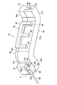
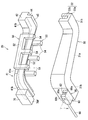
- FIG. 2 and 3 are perspective views showing a hot press mold apparatus 20.
- FIG. 2 shows a state where the hot press mold apparatus 20 is closed
- FIG. 3 shows a state where the hot press mold apparatus 20 is opened.
- 4 is a plan view showing a hot press mold apparatus 20, and
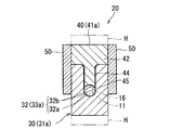
- FIG. 5 is a cross-sectional view taken along line VV of FIG. In FIG. 4, the receiving unit 70 is omitted.
- the hot pressing mold apparatus 20 is an apparatus for hot pressing the non-woven member 16 covering the plurality of electric wires 11, and includes a lower mold 30, an upper mold 40, a lever member 60, and a receiving portion 70. Prepare.
- the lower mold 30 is a long member formed of a metal having excellent thermal conductivity, and a lower mold surface 32 is formed on one main surface side (upper surface side).
- the lower mold 30 is formed with a lower mold surface 32 formed in a concave groove shape along a line in the center portion in the width direction.
- the lower mold surface 32 includes a bottom surface 32a formed in a semicircular cylinder outer peripheral surface shape, and a pair of side surfaces 32b rising upward from both side portions of the bottom surface 32a.
- the bottom surface 32a of the lower mold surface 32 has a concave shape when viewed from above. Therefore, when the lower mold surface 32 is observed in a cross section orthogonal to the extending direction, it has a U shape.
- the lower mold 30 includes a first lower mold part 31a extending linearly, and a pair of second lower mold parts 31b extending in a direction intersecting with the first lower mold part 31a. Is provided.
- the second lower mold portion 31b extends in a straight line, and is continuous with both end portions of the first lower mold portion 31a via bent portions.
- the lower mold surface 32 also includes a first lower mold surface portion 33a formed on the first lower mold portion 31a and a pair of second mold surfaces formed on the pair of second lower mold portions 31b according to the shape of the lower mold 30. 2 lower mold surface portion 33b.
- the first lower mold surface portion 33a extends in a straight line, and the pair of second lower mold surface portions 33b are continuous with both ends of the first lower mold surface portion 33a via bending portions, It extends in a direction intersecting the first lower mold surface portion 33a.
- the lower mold surface 32 extends while inclining also in the height direction of the lower mold 30.
- the lower mold surface 32 can be provided with a plurality of electric wires 11 and a non-woven member 16 that covers the plurality of electric wires 11.
- the bottom surface 32 a of the lower mold surface 32 is a part for forming a lower part of the protection member 14.
- the upper mold 40 is a long member that is formed of a metal having excellent thermal conductivity and extends along the same path as the lower mold 30, and includes an upper mold base 42 and a mold protrusion 44.
- the upper mold 40 corresponds to the first upper mold part 41a extending linearly corresponding to the first lower mold part 31a and the second lower mold part 31b according to the shape of the lower mold 30, And a second upper mold part 41b extending in a direction intersecting the first upper mold part 41a.
- the upper mold base 42 is formed in a portion having the same width as the width dimension of the lower mold 30. In a state where the lower mold 30 and the upper mold 40 are closed, both side surfaces of the lower mold 30 and both side surfaces of the upper mold 40 are arranged flush with each other.
- the mold projecting portion 44 is a portion projecting along the central portion in the width direction of the lower portion of the upper mold base 42. That is, the mold projecting portion 44 is formed in a projecting shape along the extended shape of the upper mold 40.
- the mold protrusion 44 is configured to be disposed in the lower mold surface 32. More specifically, an upper mold surface 45 formed in a semi-cylindrical outer peripheral surface shape is formed at the tip of the mold protrusion 44.
- the upper mold surface 45 has a concave shape when viewed from below.
- the upper mold surface 45 is inclined in the height direction according to the inclination of the lower mold surface 32 in the height direction.
- the width dimension of the mold projecting portion 44 is set to be approximately the same as the width dimension of the lower mold surface 32.
- the mold protrusion 44 can be disposed in the lower mold surface 32 while being in contact with both side surfaces of the mold protrusion 44 and both side surfaces 32b of the lower mold surface 32. In this state, a columnar space is formed between the bottom surface 32a of the lower mold surface 32 and the upper mold surface 45 while being bent in accordance with the shape of the protection member 14 to be processed.
- the non-woven member 16 that covers the plurality of electric wires 11 can be compressed between the lower mold surface 32 and the upper mold surface 45.
- the lower mold 30 and the upper mold 40 are provided with a heater H as a heating device.
- the heater H heats the lower mold surface 32 and the upper mold surface 45 to a temperature lower than the melting point of the basic fiber and higher than the melting point of the adhesive resin.
- the upper mold 40 is provided with a pair of guide portions 50.
- the pair of guide portions 50 are provided on both side portions of the upper mold 40.
- the pair of guide portions 50 are provided on both side portions of the first upper mold portion 41 a of the upper mold 40.
- the guide part 50 is a part integrally formed of resin or the like, and includes a support fixing part 52 and a guide convex part 54.
- the support fixing part 52 is fixed to the side part of the first upper mold part 41a by screws or the like.
- a plurality of (more specifically three) guide convex portions 54 are provided, and are formed in a square bar shape extending from the support fixing portion 52 toward the lower mold 30 side.
- the plurality of guide convex portions 54 are provided at intervals in the extending direction of the first upper mold portion 41a.
- the protrusion dimension of the guide protrusion 54 is set larger than the protrusion dimension of the mold protrusion 44.
- the inward surface of the guide convex portion 54 extends along the side surface of the upper base portion of the first upper mold portion 41a, and the guide convex portion is closed with the lower die 30 and the upper die 40 closed.
- the inward surface 54 is in contact with the side surface of the first lower mold portion 31 a of the lower mold 30.
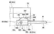
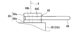
- FIG. 6 is a side view showing the lever member 60 and the receiving portion 70
- FIG. 7 is a plan view showing the lever member 60
- FIG. 8 is an explanatory view showing the operation of the lever member 60.
- the lower mold 30 is provided with a lever member 60 and the upper mold 40 is provided with a receiving portion 70.
- the lever member 60 may be provided on one of the lower die 30 and the upper die 40 and the receiving portion 70 may be provided on the other. Therefore, the lever member is provided on the upper die and the receiving portion is provided on the lower die. It may be provided. In this case, the structure of the lever member 60 and the receiving part 70 which are demonstrated below should just be provided in the reverse relationship.
- the lever member 60 includes a plate portion 62 and an operation portion 66 connected to one end portion of the plate portion 62, and is formed in an elongated shape as a whole.
- the plate portion 62 is a member formed by processing a thick metal plate or the like, and has a shape surrounded by a bottom surface 63a, a side surface 63b, a curved side surface 63c, and an upper curved surface 64 (FIG. 6). reference).
- the bottom surface 63a extends in a straight strip shape along the bottom surface of the lower mold 30.
- the side surface 63b rises in a direction perpendicular to the bottom surface 63a from one end portion of the bottom surface 63a (outward of the end of the lower mold 30).
- the curved side surface 63c is formed so as to face a direction away from the side surface 63b in a direction rising in a vertical direction with respect to the bottom surface 63a while drawing a curved surface convex toward the outer peripheral side from the other end portion of the bottom surface 63a.
- the upper curved surface 64 is formed in a shape connecting the side surface 63b, the upper end portion, and the upper end portion of the curved side surface 63c while drawing a curved surface that is convex upward.
- the lever member 60 is rotatably supported by a lever support portion 69. That is, the lever support portion 69 includes a pair of elongated plate-like support plate portions 69a and a support shaft portion 69b.
- One support plate part 69a is fixed to one side surface of the end part of the second lower mold part 31b on one side of the lower mold 30 by screwing or the like.
- One end portion of the support shaft portion 69b is inserted and fixed to the one support plate portion 69a, and the other support plate portion 69a is inserted and supported by the other end portion of the support shaft portion 69b.
- a pair of support plate part 69a is supported at intervals.
- a member that supports a constant interval may be provided between the pair of support plate portions 69a.
- a bottom portion 69c that connects the bottom portions to the bottom side of the pair of support plate portions 69a. Is provided (see FIG. 6).
- a hole 62h through which the support shaft portion 69b can be inserted is formed in an inner portion of the curved side surface 63c of the plate portion 62 of the lever member 60.
- the support shaft portion 69b is inserted into the hole 62h.
- the lever member 60 is rotatably supported with the central axis of the support shaft portion 69b as the support shaft X.
- the support shaft X is orthogonal to the approaching / separating movement direction (vertical direction) of the upper mold 40 relative to the lower mold 30.
- the posture (horizontal posture) in which the bottom surface 63a coincides with the bottom surface of the lower mold 30 is the initial state, and the side surface 63b is moved upward from that state to move the bottom surface 63a to a predetermined angle (greater than 0 degrees).
- the tilted posture is an angle smaller than 90 degrees (here, 45 degrees).
- the operation unit 66 is formed in a rod shape with metal or the like. One end portion of the operation portion 66 is connected to the plate portion 62 by being inserted through a hole formed in the plate portion 62. Here, the operation portion 66 is connected to the plate portion 62 so as to extend outward from the side surface 63b.
- the extending direction of the operation unit 66 coincides with the extending direction of the bottom surface 63 a of the plate unit 62. For this reason, in a state where the lever member 60 is in the initial state, the operation portion 66 extends along the horizontal direction (a direction coinciding with the bottom surface of the lower die 30) and is outward from the end portion of the lower die 30. It extends to.
- the shaft In the lifted state, the shaft is rotated by a predetermined angle (here 45 degrees) around the support shaft X.
- a predetermined angle here 45 degrees
- the non-woven member 16 (protective member 14) attached to the upper mold surface 45 or the lower mold surface 32 is peeled off, or It has been confirmed that the non-woven member 16 jammed between the upper mold 40 and the upper mold 40 is removed from between them.
- a later-described action surface 64C pushes the receiving portion 70, so that the lower die 30 is set to float about 5 mm with respect to the upper die 40.
- the operation unit 66 is provided at a position away from the support shaft X.
- the intermediate portion 64A in the extending direction of the upper curved surface 64 is at the highest position, and the end of the upper curved surface 64 is at a position close to the end of the lower mold 30 (a position far from the support shaft X).
- the part 64B is at a lower position than the intermediate part 64A (see FIG. 6).
- the action surface 64C which is the action portion between the intermediate portion 64A and the end portion 64B, of the upper curved surface 64 is above the line M (see FIG. 6) connecting the support shaft X and the operation portion 66.
- It is curved to be convex toward the mold 40 and has a curved surface that gradually approaches a line M connecting the support shaft X and the operation unit 66 from the support shaft X toward the operation unit 66.
- the distance of each part of the action surface 64 ⁇ / b> C with respect to the support shaft X is smaller than the distance between the support shaft X and the operation unit 66.
- the action surface 64C is provided between the support shaft X and the operation unit 66, but it is not always necessary to have such a positional relationship.
- the action portion that presses the receiving portion 70 may be provided on the opposite side of the operation portion 66 with respect to the support shaft X when viewed as the entire lever member. Even in this case, it is only necessary that the distance of the action portion with respect to the support shaft is smaller than the distance between the support shaft and the operation portion.
- the receiving portion 70 is provided on the side surface of the upper portion of the lever member 60 in the first upper mold portion 41a of the upper mold 40.
- the receiving part 70 is a metal member, and is fixed to the upper mold 40 by screwing or the like.
- a receiving surface 70 f that is a downward surface of the receiving portion 70 extends so as to be orthogonal to the approaching / separating movement direction of the lower mold 30 and the upper mold 40.
- the receiving surface 70f is a portion of the working surface 64C of the lever member 60 that is close to the support shaft X. (Intermediate portion 64A) is in contact. In this state, the action surface 64C and the receiving surface 70f do not need to be in contact with each other, and the action surface and the receiving surface are set to start to contact with the lever member 60 rotated halfway. May be.
- the action surface 64C comes into contact with the receiving surface 70f, and the lower die 30 and the upper die 40 are brought together. Moves relative to the separation direction.
- the receiving portion 70 sequentially contacts and pushes up while moving from the portion close to the support shaft X toward the portion close to the operation portion 66 of the working surface 64C. Receive power. Thereby, the lower mold
- a sheet-like nonwoven member 16 is wound around the plurality of electric wires 11. And the non-woven member 16 which covers the some electric wire 11 and the some electric wire 11 is arrange
- the non-woven member 16 is not completely fixed to the plurality of electric wires 11, but by disposing the non-woven member 16 together with the plurality of electric wires 11 so as to be pushed into the lower mold surface 32, The state in which the non-woven member 16 covers the plurality of electric wires 11 is maintained.
- step ( b) the mold projecting portions 44 are disposed in the lower mold surface 32 and the two are combined.
- the mold projecting portion 44 is disposed in the lower mold surface 32, the inward surfaces of the pair of guide portions 50 are in contact with both side portions of the lower mold 30, and the contact state is maintained.
- a mold protrusion 44 is disposed in the lower mold surface 32. For this reason, it becomes difficult for the lower mold surface 32 of the mold projecting portion 44 to come into contact with the peripheral edge of the upper mold opening of the lower mold surface 32 of the lower mold 30, and damage to the lower mold surface 32 is suppressed.
- the mold projecting portion 44 when the mold projecting portion 44 is disposed in the lower mold surface 32 and further pushed downward, the inward surfaces of the pair of guide portions 50 are in contact with both side portions of the lower mold 30. Therefore, the inclination of the mold protrusion 44 within the lower mold surface 32 is also effectively suppressed. For this reason, the side edge portion of the lower mold surface 32 of the mold projecting portion 44 is less likely to contact the side surface 32b of the lower mold surface 32 with the peripheral edge of the upper mold opening with a large force, and the side edge portion of the lower mold surface 32 is damaged. Effectively suppressed.
- the nonwoven member 16 is heated while compressing the nonwoven member 16 between the lower mold surface 32 and the upper mold surface 45 (step (c)). Then, the non-woven member 16 is molded into a shape corresponding to the lower mold surface 32 and the upper mold surface 45.
- step (d) the operator lifts the operating portion 66 of the lever member 60 upward and rotates the lever member 60 around the support shaft X (step (d)).
- the lever member 60 is rotated 45 degrees around the support shaft X to change the posture from the initial state to the lifted state (see FIG. 8).
- the action surface 64C is curved so as to be convex toward the upper mold 40 with respect to the line M connecting the support shaft X and the operation portion 66, and the support surface X extends from the operation shaft 66 to the operation portion 66.
- a curved surface that gradually approaches a line M connecting the support shaft X and the operation unit 66 as it goes is shown. For this reason, as the lever member 60 is rotated, the receiving portion 70 contacts and pushes up while moving sequentially from the portion close to the support shaft X to the portion close to the operating portion 66 of the working surface 64C. .
- the lower mold 30 can be moved in the direction away from the upper mold 40 with the equal speed and the equal force as much as possible by the moving operation of the operation unit 66. That is, assume that the operation unit 66 is moved in the first half L1 and the second half L2 is moved (see FIG. 8). As the operation portion 66 is rotated greatly, the receiving portion 70 comes into contact with the action surface 64C at a position away from the support shaft X, and therefore attempts to move the upper die 40 more greatly.
- the action surface 64C is a curved surface that gradually approaches the line M connecting the support shaft X and the operation unit 66 toward the operation unit 66 from the support shaft X with respect to the line M connecting the support shaft X and the operation unit 66.
- the lower mold 30 can be moved in a direction away from the upper mold 40 at an equal speed and with an equal force as much as possible.
- the movement amount D1 of the lower mold 30 corresponding to the movement amount L1 of the first half of the operation unit 66 and the movement amount D2 of the lower mold 30 corresponding to the movement amount L2 of the second half of the operation unit 66 are the same, The force required to move them can be made the same as much as possible.
- the action surface 64C has an upwardly convex curved surface, the contact and movement between the action surface 64C and the receiving surface 70f are also performed smoothly.
- the nonwoven member 16 (protective member) attached to the upper mold surface 45 or the lower mold surface 32. 14) is peeled off, or the non-woven member 16 clogged between the lower mold 30 and the upper mold 40 is removed from between them.
- the operator grasps the upper die 40 and lifts it upward, removes the upper die 40 from the lower die 30, and removes the plurality of electric wires 11 and the protective member 14 from the lower die surface 32, thereby completing the electric wire 10 with the protective member. To do.
- the upper mold 40 In the state where the upper mold 40 is removed from the lower mold 30, the work for removing the plurality of electric wires 11 and the protection member 14 and the work for setting the plurality of electric wires 11 and the non-woven member 16 in the lower mold surface 32 are performed. In any case, the upper mold 40 is placed in any place. At this time, the upper mold 40 can be placed on the work table such that the lower portions of the pair of guide portions 50 are placed on the work table. In this state, since the pair of guide portions 50 protrude larger than the mold protrusion 44, the mold protrusion 44 does not contact the work table and is positioned above the work table. For this reason, the upper mold 40 can be placed on the work table while avoiding contact between the mold protrusion 44 and the work table.
- the operator operates the operation portion 66 to rotate the lever member 60 around the support shaft X. Then, the working surface 64C comes into contact with the receiving portion 70, and the lower mold 30 and the upper mold 40 are relatively moved in the separation direction. At this time, since the distance between the support shaft X and the action surface 64C is smaller than the distance between the support shaft X and the operation portion 66, the operator operates the operation portion 66 with a relatively small force. That's fine.
- the lever member 60 and the receiving portion 70 are provided at positions from the end portions of the lower die 30 and the upper die 40, the non-woven member 16 attached to the upper die surface 45 or the lower die surface 32, the lower die 30 or the end of the upper mold 40 is peeled off sequentially.
- the non-woven member 16 clogged between the lower mold 30 and the upper mold 40 is sequentially removed from the end of the lower mold 30 or the upper mold 40. For this reason, the upper mold 40 can be easily detached from the lower mold 30.
- the lever member 60 can be made compact.
- the action surface 64C is curved so as to be convex toward the upper mold 40 with respect to the line M connecting the support shaft X and the operation portion 66, and further, as the support surface X moves toward the operation portion 66. Since it is formed in a curved surface that gradually approaches the line M, as the lever member 60 is rotated, the receiving portion 70 moves from a portion close to the support shaft X to a portion close to the operation portion 66 of the operating surface 64C. Because of the contact, the lever member 60 can be operated smoothly, and the lower mold 30 and the upper mold 40 can be smoothly moved relatively apart from each other. Moreover, the damage in the part which the working surface 64C contacts among the receiving parts 70 can be suppressed.
- the electric wire 10 with a protective member can be manufactured using the hot pressing mold apparatus 20 in an environment where the upper die 40 can be easily removed from the lower die 30 in this way, The electric wire 10 can be manufactured easily and efficiently.
Landscapes
- Engineering & Computer Science (AREA)
- Mechanical Engineering (AREA)
- Architecture (AREA)
- Civil Engineering (AREA)
- Structural Engineering (AREA)
- Manufacturing & Machinery (AREA)
- Details Of Indoor Wiring (AREA)
- Manufacturing Of Electric Cables (AREA)
Abstract
不織布をホットプレスするためのホットプレス用成形型装置において、下型から上型を容易に取外せるようにすることを目的とする。ホットプレス用成形型装置は、下型面が形成された下型と、下型に対して接近して合体した状態で、下型面との間で電線を覆う不織部材を圧縮する上型面が形成された上型とを備える。下型及び上型の一方に、支軸周りに回転可能に支持され、支軸から離れた位置に設けられた操作部と、支軸に対する距離が、支軸と操作部との間の距離よりも小さい位置に設けられた作用部(例えば、作用面)とを含むレバー部材が設けられる。下型及び上型の他方に、レバー部材が回転する際に、作用部に当接して、下型及び上型を離隔方向に相対移動させる受部が設けられている。
Description
この発明は、電線の周りに不織部材によって形成された保護部材を形成するための技術に関する。
特許文献1は、電線に巻付けられた不織布を加熱及び加圧する成形型を開示している。成形型は、第1の成形型と第2の成形型とを備える。第1の成形型は溝状の構造を有しており、第2の成形型は突状の構造を有している。そして、第1の成形型の溝内に、電線に巻付けられた不織布を配設し、その上に第2の成形型を嵌め込むことによって、不織布が加熱及び加圧される。
しかしながら、特許文献1に記載の技術によると、不織布が型面に貼付いてしまったり、不織布が第1の成形型と第2の成形型との間に詰ってしまったりすることがある。これらの場合、第1の成形型から第2の成形型を取外すことが困難となってしまう。
ここで、例えば、第1の成形型にネジを螺合可能に設け、締付け方向に螺合させることによって移動するネジの先端部を第2の成形型に当接させることにより、第1の成形型に対して第2の成形型を浮かせて、第1の成形型から第2の成形型を容易に取外せるようにすることが考えられる。
しかしながら、この構成の場合、作業者は、ねじ回し等を用いてネジを回転させる必要があり、その作業が面倒である。
そこで、本発明は、不織布をホットプレスするためのホットプレス用成形型装置において、下型から上型を容易に取外せるようにすることを目的とする。
上記課題を解決するため、第1の態様は、電線を覆う不織部材をホットプレスするためのホットプレス用成形型装置であって、電線及び前記電線を覆う不織部材を配設可能な溝状の下型面が形成された下型と、前記下型に対して接近して合体した状態で、前記下型面との間で前記電線を覆う前記不織部材を圧縮する上型面が形成された上型と、を備え、前記下型及び前記上型の一方に、前記下型に対する前記上型の接近離隔移動方向に対して直交する支軸周りに回転可能に支持され、前記支軸から離れた位置に設けられた操作部と、前記支軸に対する距離が、前記支軸と前記操作部との間の距離よりも小さい位置に設けられた作用部とを含むレバー部材が設けられ、前記下型及び前記上型の他方に、前記下型と前記上型とを合体させた状態で前記レバー部材が前記支軸周りに回転する際に、前記作用部に当接して、前記下型及び前記上型を離隔方向に相対移動させる受部が設けられているものである。
第2の態様は、第1の態様に係るホットプレス用成形型装置であって、前記レバー部材及び前記受部が、前記下型及び前記上型の端部よりの位置に設けられているものである。
第3の態様は、第1又は第2の態様に係るホットプレス用成形型装置であって、前記レバー部材において、前記作用部が前記支軸と前記操作部との間に設けられているものである。
第4の態様は、第3の態様に係るホットプレス用成形型装置であって、前記作用部が、前記支軸と前記操作部とを結ぶラインに対して前記下型及び前記上型の他方側に向けて凸となるように湾曲すると共に、前記支軸側から前記操作部に向うに従って前記支軸と前記操作部とを結ぶラインに順次近づく曲面を有し、前記レバー部材を回転させるに従って、前記受部が前記曲面のうちの前記支軸側に近い部分から前記操作部側に近い部分に向けて移動しつつ接触するものである。
第5の態様は、第1~第4のいずれか1つの態様に係るホットプレス用成形型装置を用いた保護部材付電線の製造方法であって、(a)前記電線及び前記電線を覆う不織部材を、前記下型の下型面内に配設する工程と、(b)前記工程(a)の後、前記下型と前記上型とを合体させる工程と、(c)前記工程(b)の後、前記下型面と前記上型面との間で前記不織部材を圧縮しつつ前記不織部材を加熱する工程と、(d)前記工程(c)の後、前記レバー部材を回転させることで、前記下型と前記上型とを相対的に離隔移動させる工程とを備える。
第1の態様に係るホットプレス用成形型装置によると、作業者が操作部を操作して、レバー部材を支軸周りに回転させると、作用部が受部に当接して、下型及び上型を離隔方向に相対移動させる。この際、支軸と作用部との間の距離は、前記支軸と前記操作部との間の距離よりも小さいため、作業者は比較的軽い力で操作部を操作すればよい。そして、下型及び上型を離隔方向に相対移動させれば、上型面又は下型面に貼付いた不織部材が剥がされ、又は、下型と上型の間に詰った不織部材がそれらの間から脱する。このため、不織布をホットプレスするためのホットプレス用成形型装置において、下型から上型を容易に取外すことができる。
第2の態様によると、上型面又は下型面に貼付いた不織部材が、下型及び上型の端部から順次剥がされ、又は、下型と上型に詰った不織部材が、下型及び上型の端部から順次それらの間から脱する。このため、不織布をホットプレスするためのホットプレス用成形型装置において、下型から上型をより容易に取外すことができる。
第3の態様によると、前記作用部が前記支軸と前記操作部との間に設けられているため、レバー部材をコンパクト化できる。
第4の態様によると、前記作用部が、前記支軸と前記操作部とを結ぶラインに対して前記下型及び前記上型の他方側に向けて凸となるように湾曲すると共に、前記支軸側から前記操作部に向うに従って前記支軸と前記操作部とを結ぶラインに順次近づく曲面を有し、前記レバー部材を回転させるに従って、前記受部が前記曲面のうちの前記支軸側に近い部分から前記操作部側に近い部分に向けて移動しつつ接触するため、レバー部材を円滑に操作することができ、かつ、下型と上型とを円滑に相対的に離隔移動させることができる。また、受部のうち作用部の曲面と接触する部分での傷付を抑制することができる。
第5の態様によると、下型から上型を容易に取外すことができるので、保護部材付電線を容易にかつ効率よく製造できる。
以下、実施形態に係るホットプレス用成形型装置及び保護部材付電線の製造方法について説明する。
図1は製造対象となる保護部材付電線10を示す斜視図である。
保護部材付電線10は、少なくとも1本の電線11と、保護部材14とを備える。
ここでは、複数の電線11が束ねられた構成とされている。複数の電線11は、本保護部材14の延在方向の途中又は外部で分岐していてもよい。少なくとも1本の電線11に対して、光ファイバケーブルが一緒に束ねられていてもよい。
上記電線11の端部には、端子が取付けられ、当該端子はコネクタに組込まれる。そして、本保護部材付電線10が車両等における配設対象箇所に配設された状態で、コネクタが車両等に搭載された各種電気機器側のコネクタに接続される。これにより、本保護部材付電線10は、車両等に搭載された各種電気機器同士を電気的に接続する配線として用いられる。
保護部材14は、不織部材が、上記複数の電線11の長手方向の中間部の少なくとも一部(ここでは一部)を覆った状態で、ホットプレスされることにより形成されている。
ここで、不織部材としては、加熱及び加圧工程を経ることにより硬くなり、かつ、相互接合可能な不織材料が用いられる。
かかる不織材料としては、絡み合う基本繊維と、接着樹脂(バインダとも呼ばれる)とを含むものを用いることができる。接着樹脂は、基本繊維の融点よりも低い融点を有する樹脂である。そして、不織材料を、基本繊維の融点よりも低くかつ接着樹脂の融点よりも高い加工温度に加熱することで、接着樹脂が溶融して基本繊維間に染みこむ。この後、不織材料が接着樹脂の融点よりも低い温度になると、基本繊維同士を結合した状態で接着樹脂が固化する。これより、不織材料が加熱前の状態よりも硬くなり、加熱時の成形形状に維持されるようになる。また、不織部材の接触部分にも接着樹脂が染込んで固化することで、不織部材の当該接触部分同士を接合する。かかる不織材料は、不織布ともいわれる。
接着樹脂は、粒状であっても繊維状であってもよい。芯繊維の外周に接着樹脂層を形成してバインダ繊維を構成し、これを基本繊維と絡み合わせるようにしてもよい。この場合の芯繊維としては、上記基本繊維と同材料のものを用いることができる。
上記基本繊維としては、接着樹脂の融点で繊維状態を保ち得るものであればよく、樹脂繊維の他、各種繊維を用いることができる。また、接着樹脂としては、基本繊維の融点よりも低い融点を持つ熱可塑性樹脂繊維を用いることができる。基本繊維と接着樹脂の組合わせとしては、基本繊維をPET(ポリエチレンテレフタレート)の樹脂繊維とし、接着樹脂をPETとPEI(ポリエチレンイソフタレート)の共重合樹脂とした例が挙げられる。この場合、基本繊維の融点は接着樹脂の融点よりも大きく、このため、不織材料をその融点間の温度に加熱すると、接着樹脂が溶融し、溶融せずに繊維状を保つ基本繊維間に染込む。そして、不織材料が接着樹脂の融点よりも低い温度になると、基本繊維同士を結合した状態で接着樹脂が固化し、不織材料は硬くなって加熱時の成形形状を維持する。つまり、上記不織材料を、成型用の金型面を有する金型間に挟込み、加熱状態で金型に圧を加えることで、不織材料が前記金型面に応じた所定形状に金型成型され、冷却されると、当該金型成型された形状に維持される。また、不織部材の相互接触部分では、溶融した接着樹脂が相手側の部分に染みこんだ後、固化する。これにより、不織部材の相互接触部分同士が接合される。上記加工方法はホットプレスとよばれる。
ここでは、保護部材14は、途中で曲る長尺形状に形成されている。より具体的には、保護部材14は、第1直線部分14aと、その第1直線部分14aの両端側で曲って第1直線部分14aに対して交差する方向に延在する2つの第2直線部分14bとを備える。
そして、保護部材14によって、複数の電線11が束ねられた状態に保持されると共に、所定の経路に沿った形状に維持される。
図2及び図3はホットプレス用成形型装置20を示す斜視図である。図2はホットプレス用成形型装置20を閉じた状態を示しており、図3はホットプレス用成形型装置20を開いた状態を示している。また、図4はホットプレス用成形型装置20を示す平面図であり、図5は図4のV-V線断面図である。なお、図4では受部70が省略されている。
ホットプレス用成形型装置20は、上記複数の電線11を覆う不織部材16をホットプレスするための装置であり、下型30と、上型40と、レバー部材60と、受部70とを備える。
下型30は、熱伝導性に優れた金属等により形成された長尺部材であり、その一主面側(上面側)に下型面32が形成されている。ここでは、下型30には、その幅方向中央部のラインに沿って凹溝状に形成された下型面32が形成されている。より具体的には、下型面32は、半円柱外周面状に形成された底面32aと、その底面32aの両側部から上方に立上がる一対の側面32bとを含む。下型面32の底面32aは、上方から見て凹形状をなしている。従って、下型面32を、その延在方向に対して直交する断面で観察すると、U字状をなしている。
また、ここでは、下型30は、直線状に延在する第1下型部分31aと、その第1下型部分31aに対して交差する方向に延在する一対の第2下型部分31bとを備える。第2下型部分31bは直線状に延在しており、第1下型部分31aの両端部に対して曲げ部を介して連続している。
下型面32も、上記下型30の形状に応じて、第1下型部分31aに形成された第1下型面部分33aと、一対の第2下型部分31bに形成された一対の第2下型面部分33bとを含む。第1下型面部分33aは、直線状に延在しており、一対の第2下型面部分33bは、第1下型面部分33aの両端部に対して曲げ部を介して連続し、第1下型面部分33aに対して交差する方向に延在している。なお、ここでは、下型面32は、下型30の高さ方向においても、傾斜しつつ延在している。
この下型面32に、複数の電線11及び複数の電線11を覆う不織部材16を配設することができる。また、下型面32の底面32aは、保護部材14の下方部分を形作るための部分である。
上型40は、熱伝導性に優れた金属等により形成され、上記下型30と同じ経路に沿って延在する長尺部材であり、上型基部42と、型突出部44とを備える。
上型40は、上記下型30の形状に応じて、第1下型部分31aに対応して直線状に延在する第1上型部分41aと、第2下型部分31bに対応して、第1上型部分41aに対して交差する方向に延在する第2上型部分41bとを含む。
上型基部42は、下型30の幅寸法と同じ幅を有する部分に形成されている。そして、下型30と上型40とを閉じた状態で、下型30の両側面と上型40の両側面とが、面一状に配設されるようになっている。
型突出部44は、上型基部42の下部の幅方向中央部に沿って突設された部分である。つまり、型突出部44は、上型40の延在形状に沿う突起状に形成されている。この型突出部44は、下型面32内に配設可能に構成されている。より具体的には、型突出部44の先端部には、半円柱外周面状に形成された上型面45が形成されている。上型面45は下方から見て凹形状をなしている。
また、ここでは、上型面45は、上記下型面32の高さ方向の傾斜に応じて、その高さ方向に傾斜している。また、型突出部44の幅寸法は、下型面32の幅寸法と同じ程度に設定されている。
そして、型突出部44の両側面と下型面32の両側面32bに接触させるようにしつつ、型突出部44を下型面32内に配設することができる。この状態で、下型面32の底面32aと上型面45との間に、加工対象となる保護部材14の形状に応じて曲りつつ連なる円柱状の空間が形成されるようになっている。この下型面32と上型面45との間で、複数の電線11を覆う不織部材16を圧縮することができる。
なお、上記下型30及び上型40には、加熱装置としてのヒータHが設けられる。ヒータHは、下型面32及び上型面45を、基本繊維の融点よりも低くかつ接着樹脂の融点よりも高い温度に加熱するものである。
本実施形態では、上型40に一対のガイド部50が設けられている。一対のガイド部50は、上型40の両側部に設けられている。ここでは、一対のガイド部50は、上型40の第1上型部分41aの両側部に設けられている。
ガイド部50は、樹脂等によって一体形成された部品であり、支持固定部52とガイド凸部54とを備える。支持固定部52は、第1上型部分41aの側部にネジ止等によって固定されている。ガイド凸部54は、ここでは複数(より具体的3つ)設けられており、支持固定部52から下型30側に向けて延在する角棒状に形成されている。複数のガイド凸部54は、第1上型部分41aの延在方向において間隔をあけて設けられている。ガイド凸部54の突出寸法は、型突出部44の突出寸法よりも大きく設定されている。また、ガイド凸部54の内向き面は、第1上型部分41aの上型基部の側面に沿って延在しており、下型30と上型40とを閉じた状態で、ガイド凸部54の内向き面が、下型30の第1下型部分31aの側面に接触するようになっている。そして、下型30に対して上型40を閉じる際に、一対のガイド部50の内向き面が、下型30の両側面に接触し、下型30の第1下型部分31aの幅方向において上型40の第1上型部分41aの位置を一定にして、型突出部44が下型面32内に配設されるように案内する。
図6はレバー部材60及び受部70を示す側面図であり、図7はレバー部材60を示す平面図であり、図8はレバー部材60の動作を示す説明図である。
図2~図4、図6~図8に示すように、下型30にレバー部材60が設けられると共に、上型40に受部70が設けられている。なお、下型30及び上型40の一方にレバー部材60が設けられる共に、他方に受部70が設けられていればよく、従って、レバー部材が上型に設けられ、受部が下型に設けられていてもよい。この場合、下記に説明するレバー部材60及び受部70の構成が、上下逆の関係で設けられればよい。
レバー部材60は、板部62と、板部62の一端部に連なる操作部66とを備えており、全体として長尺形状に形成されている。
板部62は、厚い金属板を加工等することによって形成された部材であり、底面63aと、側面63bと、曲側面63cと、上側曲面64とで囲まれた形状を呈している(図6参照)。
レバー部材60の初期状態において(図6参照)、底面63aは、下型30の底面に沿って直線帯状に延在している。側面63bは、底面63aの一端部(下型30の端部外向き)から当該底面63aに対して垂直方向に立上がっている。曲側面63cは、底面63aの他端部から、外周側に凸となる曲面を描きつつ、底面63aに対して垂直方向に立上がる方向に向けて側面63bから遠ざかる方向に向うように形成されている。上側曲面64は、上側に凸となる曲面を描きつつ、側面63bと上端部と曲側面63cの上端部を結ぶ形状に形成されている。
このレバー部材60は、レバー支持部69によって回転可能に支持されている。すなわち、レバー支持部69は、細長板状の一対の支持板部69aと、支軸部69bとを備える。
下型30の一方側の第2下型部分31bの端部の一方側の側面に一方の支持板部69aがネジ止等によって固定されている。この一方の支持板部69aに支軸部69bの一端部が挿通固定され、支軸部69bの他端部に他方の支持板部69aが挿通支持されている。これにより、一対の支持板部69aが間隔をあけて支持されている。なお、一対の支持板部69aの間には、その間隔を一定に支持する部材が設けられていてもよく、ここでは、一対の支持板部69aの底側にそれらの底部同士を繋ぐ底部69cが設けられている(図6参照)。
上記レバー部材60の板部62のうち曲側面63cの内側部分に、上記支軸部69bを挿通可能な孔62hが形成されている。板部62が一対の支持板部69a間に配設された状態で、支軸部69bが孔62hに挿通されている。これにより、レバー部材60が、支軸部69bの中心軸を支軸Xとして回転可能に支持される。なお、支軸Xは、下型30に対する上型40の接近離隔移動方向(上下方向)に対して直交している。
なお、ここでは、上記底面63aを下型30の底面と一致させた姿勢(水平姿勢)が初期状態であり、その状態から側面63bを上方に移動させ底面63aを所定角度(0度よりも大きく90度よりも小さい角度、ここでは、45度)傾斜させた姿勢が持上げ状態である。
操作部66は、金属等によって棒状に形成されている。操作部66の一端部は、板部62に形成された穴に挿通されることによって板部62に連結されている。ここでは、操作部66は、側面63bから外方に延びるように板部62に連結されている。操作部66の延在方向は、板部62の底面63aの延在方向と一致している。このため、レバー部材60が初期状態にある状態では、操作部66は水平方向(下型30の底面と一致する方向)に沿って延在しており、下型30の端部よりも外方に延出している。持上げ状態では、支軸X周りに所定角度(ここでは45度)回転した状態となる。なお、通常、下型30に対して上型40が5mm程度浮けば、上型面45又は下型面32に貼付いた不織部材16(保護部材14)が剥がされ、又は、下型30と上型40との間に詰った不織部材16がそれらの間から脱することが確認されている。このため、レバー部材60を45度回転させた状態で、後述する作用面64Cが受部70を押し、もって、下型30が上型40に対して5mm程度浮くように設定している。
この操作部66は、支軸Xから離れた位置に設けられている。
レバー部材60の初期状態において、上側曲面64の延在方向中間部64Aが最も高い位置にあり、上側曲面64のうち下型30の端部に近い位置(支軸Xから遠い位置)にある端部64Bは、前記中間部64Aよりも低い位置にある(図6参照)。このため、上側曲面64のうち中間部64Aと端部64Bとの間の作用部である作用面64Cは、支軸Xと操作部66とを結ぶラインM(図6参照)に対して、上型40に向けて凸となるように湾曲しており、かつ、支軸Xから操作部66に向うに従って支軸Xと操作部66とを結ぶラインMに順次近づく曲面を呈している。支軸Xに対する作用面64Cの各部の距離は、支軸Xと操作部66との間の距離よりも小さい。
なお、レバー部材60を観察した場合、作用面64Cは、支軸Xと操作部66との間に設けられているが、必ずしもかかる位置関係である必要はない。例えば、受部70を押す作用部が、レバー部材全体としてみたときに、支軸Xに対して操作部66の反対側に設けられていてもよい。この場合でも、支軸に対する作用部の距離が、支軸と操作部との間の距離よりも小さければよい。
また、上型40の第1上型部分41aのうちレバー部材60の上方部分の側面に受部70が設けられている。受部70は、金属製の部材であり、ネジ止等によって上型40に固定されている。受部70の下向き面である受面70fは、下型30と上型40との接近離間移動方向に対して直交するように延在している。そして、下型30と上型40とが閉じられた状態で、かつ、レバー部材60が初期状態にある状態で、受面70fが上記レバー部材60の作用面64Cのうち支軸Xに近い部分(中間部64A)に当接している。なお、この状態において、作用面64Cと受面70fとが当接している必要はなく、レバー部材60を途中迄回転させた状態で、作用面と受面とが当接し始めるように設定されていてもよい。
これにより、下型30と上型40とを合体させた状態で、レバー部材60を支軸X周りに回転させると、作用面64Cが受面70fに当接して、下型30及び上型40が離隔方向に相対移動する。特に、本実施形態では、レバー部材60を回転させるに従って、受部70が作用面64Cのうち支軸Xに近い部分から操作部66に近い部分に向けて順次移動しつつ接触して、押上げる力を受ける。これにより、下型30及び上型40が離隔方向に相対移動する。
このように構成されたホットプレス用成形型装置20を用いて、保護部材付電線10を製造する方法について説明する。
まず、図9に示すように、複数の電線11にシート状の不織部材16を巻付ける。そして、複数の電線11及び複数の電線11を覆う不織部材16を、下型面32の下型面内に配設する(工程(a))。この状態では、不織部材16は複数の電線11に対して完全には固定されていないが、複数の電線11と共に不織部材16を、下型面32内に押込むように配設することによって、不織部材16が複数の電線11を覆う状態が保持される。
次に、図10に示すように、一対のガイド部50を下型30の両側部に接触させつつ、型突出部44を下型面32内に配設して、両者を合体させる(工程(b))。ここで、型突出部44を下型面32内に配設する前に、一対のガイド部50の内向き面が下型30の両側部に接触し、この接触状態が維持された状態で、型突出部44が下型面32内に配設される。このため、型突出部44の下型面32が下型30の下型面32の上型開口周縁部に接触し難くなり、下型面32の破損が抑制される。また、型突出部44を下型面32内に配設し、さらに下方に押込もうとする際にも、一対のガイド部50の内向き面が下型30の両側部に接触した状態となっているため、下型面32内での型突出部44の傾きも有効に抑制される。このため、型突出部44の下型面32の側縁部が下型面32の側面32bに上型開口周縁部に大きい力で接触し難くなり、下型面32の側縁部の破損が有効に抑制される。
この後、下型面32と上型面45との間で不織部材16を圧縮しつつ不織部材16を加熱する(工程(c))。すると、不織部材16が下型面32と上型面45とに応じた形状に成型される。
次に、作業者がレバー部材60の操作部66を上方に持上げて、レバー部材60を支軸X周りに回転させる(工程(d))。ここでは、レバー部材60を支軸X周りに45度回転させて、初期状態から持上げ状態に姿勢変更させる(図8参照)。
ここで、作用面64Cは、支軸Xと操作部66とを結ぶラインMに対して、上型40に向けて凸となるように湾曲しており、かつ、支軸Xから操作部66に向うに従って支軸Xと操作部66とを結ぶラインMに順次近づく曲面を呈している。このため、レバー部材60を回転させるのに従って、受部70が作用面64Cのうち支軸Xに近い部分から操作部66に近い部分に向けて順次移動しつつ接触して、押上げる力を受ける。
これにより、操作部66の移動操作によって、下型30をなるべく均等速度でかつ均等な力で上型40から離れる方向に移動させることができる。すなわち、操作部66を前半L1移動させる場合と、後半L2移動させる場合とを想定する(図8参照)。操作部66を大きく回転させるに従って、受部70は、支軸Xから離れた位置で作用面64Cに当接するため、上型40をより大きく移動させようとする。しかしながら、作用面64Cは、支軸Xと操作部66とを結ぶラインMに対して、支軸Xから操作部66に向うに従って支軸Xと操作部66とを結ぶラインMに順次近づく曲面を呈しているため、その分、上型40の上方への移動量は、小さくなる。結果、操作部66の移動操作に応じて、下型30をなるべく均等速度でかつ均等な力で上型40から離れる方向に移動させることができる。例えば、操作部66の前半の移動量L1に応じた下型30の移動量D1と、操作部66の後半の移動量L2に応じた下型30の移動量D2とを同じにして、また、それらの移動させる際に要する力をなるべく同じにすることができる。勿論、作用面64Cは、上向き凸状の曲面を呈しているため、作用面64Cと受面70fとの接触及び移動も円滑に行われる。
このように、レバー部材60を回転させることによって、下型30と上型40とを相対的に離隔移動させることによって、上型面45又は下型面32に貼付いた不織部材16(保護部材14)が剥がされ、又は、下型30と上型40との間に詰った不織部材16がそれらの間から脱する。
この後、作業者は、レバー部材60の操作部66を持上げる力を解除する。すると、レバー部材60は、自重によって初期状態に戻る。
この後、作業者が上型40を掴んで上方に持上げ、下型30から上型40を取外し、下型面32から複数の電線11及び保護部材14を取外すと、保護部材付電線10が完成する。
なお、下型30から上型40を取外した状態で、複数の電線11及び保護部材14を取外す作業中、及び、下型面32内に複数の電線11及び不織部材16をセットする作業中には、上型40はいずれの場所に載置される。この際、一対のガイド部50の下部を作業台上に置くようにして、上型40を作業台上に置くことができる。この状態では、一対のガイド部50は、型突出部44よりも大きく突出しているため、型突出部44が作業台には接触せず、その上方に位置した状態となる。このため、型突出部44と作業台との接触を回避しつつ、上型40を作業台上に置くことができる。
以上のように構成されたホットプレス用成形型装置20及びこれを用いた保護部材付電線10の製造方法によると、作業者が操作部66を操作してレバー部材60を支軸X周りに回転させると、作用面64Cが受部70に当接して、下型30及び上型40を離隔方向に相対移動させる。この際、支軸Xと作用面64Cとの間の距離は、支軸Xと操作部66との間の距離よりも小さいため、作業者は、比較的小さい力で、操作部66を操作すればよい。そして、下型30及び上型40を離隔方向に相対移動させれば、上型面45又は下型面32に貼付いた不織部材16が剥がされ、又は、下型30と上型40との間に詰った不織部材16がそれらの間から脱する。このため、不織部材16をホットプレスするためのホットプレス用成形型装置20において、下型30から上型40を容易に取外すことができる。
また、レバー部材60及び受部70が、下型30及び上型40の端部よりの位置に設けられているため、上型面45又は下型面32に貼付いた不織部材16、下型30又は上型40の端部から順次剥がされる。又は、下型30と上型40との間に詰った不織部材16が、下型30又は上型40の端部から順次脱する。このため、下型30から上型40をより容易に取外すことができる。
また、作用面64Cが、レバー部材60において、支軸Xと操作部66との間に設けられているため、レバー部材60をコンパクト化できる。
また、作用面64Cが、支軸Xと操作部66とを結ぶラインMに対して上型40に向けて凸となるように湾曲しており、さらに、支軸Xから操作部66に向うに従って前記ラインMに順次近づく曲面に形成されているため、レバー部材60を回転させるに従って、受部70が作用面64Cのうち支軸Xに近い部分から操作部66に近い部分に向けて移動しつつ接触するため、レバー部材60を円滑に操作することができ、下型30と上型40とを円滑に相対的に離隔移動させることができる。また、受部70のうち作用面64Cが接触する部分での傷付を抑制することができる。
また、このように、下型30から上型40を容易に取外すことができる環境下で、ホットプレス用成形型装置20を用いて保護部材付電線10を製造することができるため、保護部材付電線10を容易かつ効率的に製造できる。
以上のようにこの発明は詳細に説明されたが、上記した説明は、すべての局面において、例示であって、この発明がそれに限定されるものではない。例示されていない無数の変形例が、この発明の範囲から外れることなく想定され得るものと解される。
X 支軸
10 保護部材付電線
11 電線
14 保護部材
16 不織部材
20 ホットプレス用成形型装置
30 下型
32 下型面
40 上型
45 上型面
60 レバー部材
62 板部
64C 作用面
66 操作部
70 受部
70f 受面
10 保護部材付電線
11 電線
14 保護部材
16 不織部材
20 ホットプレス用成形型装置
30 下型
32 下型面
40 上型
45 上型面
60 レバー部材
62 板部
64C 作用面
66 操作部
70 受部
70f 受面
Claims (5)
- 電線を覆う不織部材をホットプレスするためのホットプレス用成形型装置であって、
電線及び前記電線を覆う不織部材を配設可能な溝状の下型面が形成された下型と、
前記下型に対して接近して合体した状態で、前記下型面との間で前記電線を覆う前記不織部材を圧縮する上型面が形成された上型と、
を備え、
前記下型及び前記上型の一方に、
前記下型に対する前記上型の接近離隔移動方向に対して直交する支軸周りに回転可能に支持され、前記支軸から離れた位置に設けられた操作部と、前記支軸に対する距離が、前記支軸と前記操作部との間の距離よりも小さい位置に設けられた作用部とを含むレバー部材が設けられ、
前記下型及び前記上型の他方に、前記下型と前記上型とを合体させた状態で前記レバー部材が前記支軸周りに回転する際に、前記作用部に当接して、前記下型及び前記上型を離隔方向に相対移動させる受部が設けられている、ホットプレス用成形型装置。 - 請求項1に記載のホットプレス用成形型装置であって、
前記レバー部材及び前記受部が、前記下型及び前記上型の端部よりの位置に設けられている、ホットプレス用成形型装置。 - 請求項1又は請求項2に記載のホットプレス用成形型装置であって、
前記レバー部材において、前記作用部が前記支軸と前記操作部との間に設けられている、ホットプレス用成形型装置。 - 請求項3に記載のホットプレス用成形型装置であって、
前記作用部が、前記支軸と前記操作部とを結ぶラインに対して前記下型及び前記上型の他方側に向けて凸となるように湾曲すると共に、前記支軸側から前記操作部に向うに従って前記支軸と前記操作部とを結ぶラインに順次近づく曲面を有し、
前記レバー部材を回転させるに従って、前記受部が前記曲面のうちの前記支軸側に近い部分から前記操作部側に近い部分に向けて移動しつつ接触する、ホットプレス用成形型装置。 - 請求項1~請求項4のいずれか1つに記載のホットプレス用成形型装置を用いた保護部材付電線の製造方法であって、
(a)前記電線及び前記電線を覆う不織部材を、前記下型の下型面内に配設する工程と、
(b)前記工程(a)の後、前記下型と前記上型とを合体させる工程と、
(c)前記工程(b)の後、前記下型面と前記上型面との間で前記不織部材を圧縮しつつ前記不織部材を加熱する工程と、
(d)前記工程(c)の後、前記レバー部材を回転させることで、前記下型と前記上型とを相対的に離隔移動させる工程と、
を備える保護部材付電線の製造方法。
Applications Claiming Priority (2)
| Application Number | Priority Date | Filing Date | Title |
|---|---|---|---|
| JP2014-261565 | 2014-12-25 | ||
| JP2014261565A JP6172136B2 (ja) | 2014-12-25 | 2014-12-25 | ホットプレス用成形型装置及び保護部材付電線の製造方法 |
Publications (1)
| Publication Number | Publication Date |
|---|---|
| WO2016104107A1 true WO2016104107A1 (ja) | 2016-06-30 |
Family
ID=56150137
Family Applications (1)
| Application Number | Title | Priority Date | Filing Date |
|---|---|---|---|
| PCT/JP2015/084115 Ceased WO2016104107A1 (ja) | 2014-12-25 | 2015-12-04 | ホットプレス用成形型装置及び保護部材付電線の製造方法 |
Country Status (2)
| Country | Link |
|---|---|
| JP (1) | JP6172136B2 (ja) |
| WO (1) | WO2016104107A1 (ja) |
Citations (3)
| Publication number | Priority date | Publication date | Assignee | Title |
|---|---|---|---|---|
| JP2004235021A (ja) * | 2003-01-30 | 2004-08-19 | Furukawa Electric Co Ltd:The | フラットケーブルの折り曲げ装置 |
| JP2012196035A (ja) * | 2011-03-16 | 2012-10-11 | Auto Network Gijutsu Kenkyusho:Kk | ワイヤハーネス |
| JP2013143868A (ja) * | 2012-01-11 | 2013-07-22 | Sumitomo Wiring Syst Ltd | プロテクタ、経路維持ワイヤーハーネス及びプロテクタの製造方法 |
-
2014
- 2014-12-25 JP JP2014261565A patent/JP6172136B2/ja not_active Expired - Fee Related
-
2015
- 2015-12-04 WO PCT/JP2015/084115 patent/WO2016104107A1/ja not_active Ceased
Patent Citations (3)
| Publication number | Priority date | Publication date | Assignee | Title |
|---|---|---|---|---|
| JP2004235021A (ja) * | 2003-01-30 | 2004-08-19 | Furukawa Electric Co Ltd:The | フラットケーブルの折り曲げ装置 |
| JP2012196035A (ja) * | 2011-03-16 | 2012-10-11 | Auto Network Gijutsu Kenkyusho:Kk | ワイヤハーネス |
| JP2013143868A (ja) * | 2012-01-11 | 2013-07-22 | Sumitomo Wiring Syst Ltd | プロテクタ、経路維持ワイヤーハーネス及びプロテクタの製造方法 |
Also Published As
| Publication number | Publication date |
|---|---|
| JP2016122556A (ja) | 2016-07-07 |
| JP6172136B2 (ja) | 2017-08-02 |
Similar Documents
| Publication | Publication Date | Title |
|---|---|---|
| JP5108167B2 (ja) | ワイヤーハーネス、ワイヤーハーネスの製造方法 | |
| JP5920181B2 (ja) | ワイヤーハーネス及びワイヤーハーネスの製造方法 | |
| JP5353742B2 (ja) | 電線用保護部材及びその製造方法 | |
| WO2011158394A1 (ja) | 長尺物固定部付電線保護具 | |
| JP5807477B2 (ja) | ワイヤーハーネス | |
| KR20120135516A (ko) | 전선 보호구 | |
| JP5353814B2 (ja) | ワイヤーハーネスの保護構造 | |
| JP5768702B2 (ja) | ワイヤーハーネス | |
| CN103890863B (zh) | 线束及线束的制造方法 | |
| JP5359922B2 (ja) | 保護部材付電線 | |
| CN103890861A (zh) | 线束以及线束的制造方法 | |
| JP6172136B2 (ja) | ホットプレス用成形型装置及び保護部材付電線の製造方法 | |
| JP5884695B2 (ja) | ワイヤーハーネス、ワイヤーハーネスの製造方法及び保護部材 | |
| JP6172134B2 (ja) | ホットプレス用成形型装置及び保護部材付電線の製造方法 | |
| JP2014033514A (ja) | ワイヤーハーネス、ワイヤーハーネスの製造方法及びホットプレス用成形型装置 | |
| JP5556606B2 (ja) | 被覆部材付電線束および被覆部材付電線束の製造方法 | |
| KR20130018820A (ko) | 커넥터 고정구조 | |
| JP2014003757A (ja) | 経路維持保護部材及びワイヤーハーネス | |
| WO2013190725A1 (ja) | ワイヤーハーネス及びその製造方法 | |
| JP2014230321A (ja) | ワイヤーハーネス | |
| JP6015572B2 (ja) | 保護部材付ワイヤーハーネスの製造方法及びホットプレス用成形金型装置 | |
| JP2013161548A (ja) | ワイヤーハーネス及び分岐部保護部材 | |
| JP2013161556A (ja) | ワイヤーハーネス | |
| JP5182939B2 (ja) | シールド電線の処理方法 | |
| JP2013145708A (ja) | コネクタカバー、ワイヤーハーネス及びコネクタカバーの製造方法 |
Legal Events
| Date | Code | Title | Description |
|---|---|---|---|
| 121 | Ep: the epo has been informed by wipo that ep was designated in this application |
Ref document number: 15872676 Country of ref document: EP Kind code of ref document: A1 |
|
| NENP | Non-entry into the national phase |
Ref country code: DE |
|
| 122 | Ep: pct application non-entry in european phase |
Ref document number: 15872676 Country of ref document: EP Kind code of ref document: A1 |