WO2016104099A1 - 転倒防止装置 - Google Patents
転倒防止装置 Download PDFInfo
- Publication number
- WO2016104099A1 WO2016104099A1 PCT/JP2015/084042 JP2015084042W WO2016104099A1 WO 2016104099 A1 WO2016104099 A1 WO 2016104099A1 JP 2015084042 W JP2015084042 W JP 2015084042W WO 2016104099 A1 WO2016104099 A1 WO 2016104099A1
- Authority
- WO
- WIPO (PCT)
- Prior art keywords
- furniture
- ceiling
- prevention device
- contact
- article
- Prior art date
- Legal status (The legal status is an assumption and is not a legal conclusion. Google has not performed a legal analysis and makes no representation as to the accuracy of the status listed.)
- Ceased
Links
Images

Classifications
-
- A—HUMAN NECESSITIES
- A47—FURNITURE; DOMESTIC ARTICLES OR APPLIANCES; COFFEE MILLS; SPICE MILLS; SUCTION CLEANERS IN GENERAL
- A47B—TABLES; DESKS; OFFICE FURNITURE; CABINETS; DRAWERS; GENERAL DETAILS OF FURNITURE
- A47B97/00—Furniture or accessories for furniture, not provided for in other groups of this subclass
-
- A—HUMAN NECESSITIES
- A47—FURNITURE; DOMESTIC ARTICLES OR APPLIANCES; COFFEE MILLS; SPICE MILLS; SUCTION CLEANERS IN GENERAL
- A47B—TABLES; DESKS; OFFICE FURNITURE; CABINETS; DRAWERS; GENERAL DETAILS OF FURNITURE
- A47B97/00—Furniture or accessories for furniture, not provided for in other groups of this subclass
- A47B2097/008—Anti-tip devices
Definitions
- the present invention relates to a fall prevention device.
- Patent Document 1 discloses a conventional fall prevention device.
- the overturn prevention device includes a furniture pressing lower part, a ceiling contacting upper part, and a telescopic part.
- the lower part for holding the furniture is brought into contact with the upper surface of a furniture protecting plate disposed on the upper surface of the furniture.
- the upper part for the ceiling contact is brought into contact with the ceiling.
- the expansion / contraction part is disposed between the furniture pressing lower part and the ceiling contact upper part, and can be vertically extended and fixed at an arbitrary position. Since this fall prevention device can adjust the up-and-down length of an expansion-contraction part according to the height of furniture, it can be attached with respect to furniture with different height, and can prevent the fall of furniture.
- the present invention has been made in view of the above-described conventional situation, and it is an object to be solved to provide a tipping prevention device that can be easily attached and can prevent the article from tipping over.
- the fall prevention device of the first invention includes a contact portion and a connecting portion.
- the contact portion contacts the ceiling or the installation surface.
- the abutting portion is arranged to extend in one direction while gradually leaving the ceiling or the installation surface.
- One end of the connecting portion is connected to the ceiling of the abutting portion or the end away from the installation surface, and the other end is provided on an article installed on the installation surface.
- the contact portion is elastically deformed with the inclination of the article, and the area of contact with the ceiling or the installation surface increases.
- the fall prevention device of the second invention also includes a contact portion and a connecting portion.
- the abutting portion abuts on an article installed on the installation surface.
- the abutting portion is arranged to extend in one direction while gradually separating from the article.
- One end portion of the connecting portion is connected to an end portion away from the article of the contact portion, and the other end portion is provided on the ceiling or the installation surface.
- the contact portion is elastically deformed with the inclination of the article, and the area of contact with the article increases.
- the contact portion may be arranged gradually away from the ceiling or the installation surface in a direction in which the interval between the article and the ceiling or the installation surface becomes narrower when the article is tilted.
- the abutting portion abuts against the end of the article on the side approaching the ceiling or the installation surface when the article is tilted.
- This abutting portion can be arranged gradually away from the article in a direction in which the space between the ceiling and the installation surface becomes wider when the article is tilted.
- the fall prevention device of the first invention or the second invention can be attached between the article and the ceiling or the installation surface using the elastic force of the contact portion.
- the fall prevention apparatus of 1st invention or 2nd invention can have a height adjustment part which adjusts the dimension of a height direction according to the width of the space
- the installation surface includes not only the floor surface in the building but also the foundation surface on which articles are installed outside the building.
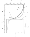
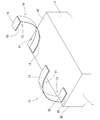
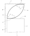
- Embodiment 1 It is a fall prevention device of Embodiment 1, Comprising: It is a side view showing the state where the contact part was made to contact the ceiling and attached between the upper surface of the furniture and the ceiling. It is a fall prevention device of Embodiment 1, Comprising: It is a side view showing the state where the contact part was made to contact the upper surface of furniture and it was attached between the upper surface of furniture and the ceiling.
- Embodiment 1 A fall prevention device in which a contact portion is in contact with the ceiling and a contact portion that is in contact with the top surface of the furniture are attached between the top surface of the furniture and the ceiling, respectively FIG.
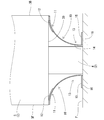
- Embodiment 2 It is a fall prevention device of Embodiment 2, Comprising: It is a side view which shows the state attached to the lower surface of furniture, and the floor surface, with the contact part contact
- Embodiments 1 to 4 embodying the overturn prevention devices of the first invention and the second invention will be described with reference to the drawings.
- the fall prevention device 10 of Embodiment 1 is a piece of furniture 1 installed on a floor surface with a back surface 1B facing a wall surface W extending vertically from a floor surface (not shown). It is attached between the upper surface 1U and the ceiling C.
- the furniture 1 has a rectangular parallelepiped shape, has a door, a drawer, and the like (not shown) on the front surface 1F, and can store clothes, accessories, and the like inside.
- the furniture 1 has a rectangular shape in which the horizontal cross-sectional shape is long in the left-right direction (the depth direction in FIG. 1). When the fall prevention device 10 is not attached, the furniture 1 may be tilted forward and tilted due to an earthquake shake or the like (rightward in FIG. 1).
- the fall prevention device 10 includes a contact portion 11 and a connecting portion 13.
- the contact part 11 is a belt-like flat plate and has elasticity.
- the contact portion 11 is curved in an arc shape.
- the contact portion 11 has a non-slip member 12 attached to one side surface of one end portion.
- the connecting portion 13 is a strip-shaped flat plate formed continuously and integrally with the other end of the abutting portion 11.
- the connecting portion 13 includes a curved portion 14 that is curved continuously from the curvature of the contact portion 11, and a straight portion 15 that is bent from the end of the curved portion 14 and extends linearly.
- the connecting portion 13 has a non-slip member 16 attached to one side surface of the straight portion 15.
- the fall prevention device 10 As shown in FIGS. 1 and 3, the fall prevention device 10 having such a configuration has an abutting portion 11 and a curved portion 14 of the connecting portion 13 in an oblique rearward upward direction (the ceiling C and the wall surface W are connected). Can be attached between the top surface 1U of the furniture 1 and the ceiling C.
- the abutting portion 11 and the curved portion 14 of the connecting portion 13 are elastically deformed to reduce the vertical dimension. .
- connection part 13 is arrange
- the contact portion 11 is gradually separated from the ceiling C in a direction in which the space between the upper surface 1U of the furniture 1 and the ceiling C becomes narrower (the direction of the back surface 1B of the furniture 1) when the furniture 1 is tilted forward. Arranged.
- the fall prevention device 10 when attaching the fall prevention device 10 between the upper surface 1U of the furniture 1 and the ceiling C, the fall force is prevented by utilizing the elastic force in the direction in which the curved portion 14 of the contact portion 11 and the connecting portion 13 extends in the vertical direction.
- the device 10 can be attached. For this reason, the fall prevention device 10 can be easily attached between the upper surface 1U of the furniture 1 and the ceiling C.
- the fall prevention device 10 when the fall prevention device 10 is attached between the upper surface 1U of the furniture 1 and the ceiling C as described above, when the furniture 1 is tilted forward due to shaking such as an earthquake, the contact portion 11 and the connecting portion are accordingly accompanied.
- the 13 curved portions 14 are elastically deformed, and the area of the contact portion 11 that contacts the ceiling C increases.
- this fall prevention device 10 relieves the force that the furniture 1 tilts by the elastic deformation of the curved portion 14 of the contact portion 11 and the connecting portion 13 when the furniture 1 tilts forward due to an earthquake shake or the like. can do.
- the fall prevention device 10 can disperse the force applied to the ceiling C because the area of the contact portion 11 that contacts the ceiling C increases when the furniture 1 tilts forward due to an earthquake shake or the like. it can.
- the fall prevention device 10 can reduce the force applied to the ceiling C, the degree of freedom of the attachment position can be increased.
- the tipping prevention device 10 is curved so that the abutting portion 11 and the curved portion 14 of the connecting portion 13 swell obliquely forward and downward, and the upper surface 1 U of the furniture 1. It can be attached to the ceiling C.
- the curved part 14 of the contact part 11 and the connection part 13 is elastically deformed, and the dimension of the up-down direction was shrunk
- connection part 13 is made to contact
- FIG. That is, when the furniture 1 is tilted forward, the contact portion 11 is brought into contact with the end portion of the upper surface 1U of the furniture 1 on the side approaching the ceiling C (the back surface 1B side of the furniture 1).
- the abutment portion 11 extends from the upper surface 1U of the furniture 1 toward the direction in which the space between the upper surface 1U of the furniture 1 and the ceiling C becomes wider (the front 1F direction of the furniture 1) when the furniture 1 is tilted forward. Be placed gradually apart.
- the fall prevention device 10 when attaching the fall prevention device 10 between the upper surface 1U of the furniture 1 and the ceiling C, the fall force is prevented by utilizing the elastic force in the direction in which the curved portion 14 of the contact portion 11 and the connecting portion 13 extends in the vertical direction.
- the device 10 can be attached. For this reason, the fall prevention device 10 can be easily attached between the upper surface 1U of the furniture 1 and the ceiling C.
- the fall prevention device 10 is applied to the upper surface 1U of the furniture 1 because the area of the contact portion 11 that contacts the upper surface 1U of the furniture 1 increases. The power can be distributed. Thus, since this fall prevention device 10 can make small the force concerning the upper surface 1U of the furniture 1, it can expand the freedom degree of an attachment position.
- the fall prevention device 10 of Embodiment 1 can be easily attached, and the furniture 1 can be prevented from falling.
- the anti-slip device 10 since the anti-slip device 10 has anti-slip members 12 and 16 attached to one side surface of one end portion of the contact portion 11 and one side surface of the straight portion 15 of the connecting portion 13, the anti-slip device 10 is shaken by an earthquake or the like. Thus, even if the furniture 1 is tilted forward, the linear portion 15 or the contact portion 11 of the connecting portion 13 can be attached to the upper surface 1U or the ceiling C of the furniture 1 without shifting. For this reason, this fall prevention device 10 can maintain the state attached between the upper surface 1U of the furniture 1 and the ceiling C even if an earthquake shakes or the like, and can prevent the furniture 1 from falling.
- the fall prevention device 10 of the second embodiment is different from the first embodiment in that it is attached between the lower surface 3D of the furniture 2 installed on the floor surface F and the floor surface F as shown in FIG.
- the form of the overturn prevention device 10 is the same as that of the first embodiment, and the same configurations as those of the first embodiment are denoted by the same reference numerals, and detailed description thereof is omitted.
- the furniture 2 includes a furniture body 3 and support legs 4 that are placed on the floor F and support the furniture body 3.
- the furniture body 3 has a rectangular parallelepiped shape, and has a door, a drawer, etc. (not shown) on the front surface 3F, and can store clothes, accessories, and the like inside.
- the furniture body 3 has a rectangular shape in which the horizontal cross-sectional shape is long in the left-right direction (the depth direction in FIG. 4).
- the support leg 4 also has a rectangular parallelepiped shape, a horizontal cross-sectional shape that is smaller than that of the furniture body 3 and a rectangular shape that is long in the left-right direction.
- the support legs 4 continuously extend downward from the center of the lower surface of the furniture body 3 so that the longitudinal direction of the support legs 4 and the longitudinal direction of the furniture body 3 are the same. For this reason, the lower surface 3D of the furniture body 3 extends from the peripheral edge of the upper end of the support leg 4 to the outside.
- the furniture 2 is self-supporting with the lower surface of the support leg 4 in contact with the floor surface F. Since the support leg 4 has a rectangular parallelepiped shape that is long in the left-right direction, the furniture 2 tilts in the front-rear direction (left-right direction in FIG. 4) due to an earthquake or the like when the fall-prevention device 10 is not attached. There is a fear.
- At least a pair of the fall prevention device 10 can be attached between the lower surface 3D of the furniture body 3 and the floor surface F with the support leg 4 interposed therebetween.
- the pair of fall prevention devices 10 attached between the lower surface 3D of the furniture body 3 and the floor surface F so as to swell in an obliquely inner upper direction (the corner direction where the lower surface 3D of the furniture body 3 and the support legs 4 are connected). Is curved.
- the abutting portion 11 and the curved portion 14 of the connecting portion 13 are elastically deformed, Reduce the vertical dimension. Then, the linear portion 15 of the connecting portion 13 is disposed on the floor surface F close to the support leg 4, and the tip portion of the contact portion 11 is brought into contact with the lower surface 3D of the front end edge of the furniture body 3. That is, the abutting portion 11 contacts the end portion of the lower surface 3D of the furniture body 3 on the side approaching the floor surface F (the front surface 3F side of the furniture 2) when the furniture 2 is tilted forward (leftward in FIG. 4). Make contact.
- This abutment portion 11 is directed toward the direction in which the space between the front lower surface 3D and the floor surface F of the furniture body 3 becomes wider (the direction of the support legs 4) when the furniture 2 is tilted forward. It is arranged gradually away from the lower surface 3D.
- the curved part 14 of the contact part 11 and the connection part 13 is elastically deformed, and it is the dimension of an up-down direction. Is in a contracted state.
- the linear part 15 of the connection part 13 is arrange
- the abutting portion 11 contacts the end of the lower surface 3D of the furniture body 3 on the side approaching the floor surface F (the back surface 1B side of the furniture 2) when the furniture 2 is tilted rearward (rightward in FIG. 4). Make contact.
- the abutment portion 11 faces the furniture body 3 in the direction in which the space between the lower surface 3D on the back side of the furniture body 3 and the floor surface F becomes wider (the direction of the support legs 4) when the furniture 2 is tilted rearward. 3 is disposed gradually away from the lower surface 3D of 3.
- the contact portion 11 and The fall prevention device 10 can be attached using the elastic force in the direction extending in the vertical direction of the curved portion 14 of the connecting portion 13. For this reason, the fall prevention device 10 can be easily attached between the lower surface 3D of the furniture body 3 and the floor surface F.
- the fall prevention device 10 when the fall prevention device 10 is attached between the lower surface 3D of the furniture body 3 and the floor surface F, when the furniture 2 is tilted in the front-rear direction due to shaking such as an earthquake, the contact portion 11 and the connecting portion are accordingly accompanied.
- the 13 curved portions 14 are elastically deformed, and the area of the contact portion 11 that contacts the lower surface 3D of the furniture body 3 increases.
- this fall prevention device 10 relieves the force by which the furniture 2 tilts by the elastic deformation of the curved portion 14 of the contact portion 11 and the connecting portion 13 when the furniture 2 tilts in the front-rear direction due to an earthquake shake or the like. can do.
- the fall prevention device 10 increases the area of the abutment portion 11 that abuts the lower surface 3D of the furniture body 3, so that the force applied to the furniture 2 is increased. Can be dispersed. Thus, since the fall prevention device 10 can reduce the force applied to the furniture 2, the degree of freedom of the attachment position can be increased.
- the fall prevention device 10 of the second embodiment can be easily attached, and the furniture 2 can be prevented from falling.
- the anti-slip device 10 has anti-slip members 12 and 16 attached to one side surface of one end portion of the contact portion 11 and one side surface of the straight portion 15 of the connecting portion 13, the anti-slip device 10 is shaken by an earthquake or the like. Even if the furniture 2 is tilted in the front-rear direction, the abutment portion 11 can be attached without being displaced with respect to the lower surface 3D of the furniture body 3. Similarly, the straight portion 15 of the connecting portion 13 can be attached without being displaced with respect to the floor surface F. For this reason, this fall prevention device 10 can maintain the state attached between the lower surface 3D of the furniture body 3 and the floor surface F even if an earthquake shakes or the like, and can prevent the furniture 2 from falling. .
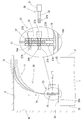
- the fall prevention device 20 according to the third embodiment is different from the first embodiment in that the connecting portion 23 has a height adjusting portion 25.
- the same forms as those of the first embodiment are denoted by the same reference numerals, and detailed description thereof is omitted.
- the connecting portion 23 of the fall prevention device 20 is formed integrally with the other end of the abutting portion 11 so as to be integrated with the insertion portion 24 extending linearly, and the insertion portion 24 is inserted to adjust the height direction.
- a support portion 26 that is installed on the upper surface 1U of the furniture 1 in succession to the lower end portion of the height adjustment portion 25.
- the insertion part 24 of the connection part 23 is also flat and has two through holes 24A. These two through-holes 24A are provided at positions separated from each other on the center line along the direction in which the insertion portion 24 extends. These two through holes 24A are circular and have the same inner diameter.
- the height adjustment unit 25 extends in the vertical direction with respect to the upper surface 1U of the furniture 1 in a state where the support unit 26 is installed on the upper surface 1U of the furniture 1, and is slightly separated from the thickness of the insertion portion 24 of the connecting portion 23.
- a pair of flat plates 27 is provided. The insertion portion 24 of the connecting portion 23 is inserted between the pair of flat plates 27.
- the height adjusting portion 25 has three sets of through holes 27A that penetrate the pair of flat plates 27. These three sets of through-holes 27A are provided at positions spaced apart at equal intervals on a straight line extending in the vertical direction. The interval between the three sets of through holes 27 ⁇ / b> A is the same as the interval between the two through holes 24 ⁇ / b> A provided in the insertion portion 24 of the connecting portion 23. Each of the three sets of through holes 27A is circular and has the same inner diameter. The inner diameters of the three sets of through holes 27 ⁇ / b> A of the height adjusting portion 25 are larger than the inner diameters of the two through holes 24 ⁇ / b> A provided in the insertion portion 24 of the connecting portion 23.
- the support portion 26 has a flat plate shape, and an anti-slip member 26 ⁇ / b> A is attached to the lower surface that comes into contact with the upper surface 1 ⁇ / b> U of the furniture 1 when installed on the upper surface 1 ⁇ / b> U of the furniture 1.
- the support portion 26 has a pair of flat plates 27 of the height adjusting portion 25 continuous with the center portion of the upper surface.
- This fall prevention device 20 has a pin 30 through which each of the three sets of through holes 27A of the height adjusting portion 25 can be inserted.
- the pin 30 has a head portion 31 and a shaft portion 32 extending continuously from the head portion 31.
- the head portion 31 has a cylindrical shape, and the outer diameter is larger than the inner diameter of each through hole 27 ⁇ / b> A of the height adjusting unit 25.
- the shaft portion 32 has a tip shape and has a tip portion 32A that spreads outward from the tip. In the normal form, the shaft portion 32 has the largest outer diameter of the tip portion 32A larger than the inner diameter of each through hole 27A of the height adjusting portion 25.
- the shaft portion 32 can be elastically deformed at the distal end portion 32 ⁇ / b> A to reduce the outer diameter, and can be inserted through each through hole 27 ⁇ / b> A of the height adjusting portion 25.
- the tip end portion 32A is locked to the through hole 27A, and the shaft portion 32 is prevented from being detached.
- the insertion portion 24 of the connecting portion 23 is inserted between the pair of flat plates 27 of the height adjusting portion 25, and the through hole 27 ⁇ / b> A and the connecting portion 23 of the height adjusting portion 25 arranged on the same straight line.
- the pin 30 can be inserted into the through hole 24A to prevent the pin 30 from coming off, and the height can be adjusted. That is, the fall prevention device 20 can adjust the height to three levels. For this reason, the space
- the fall prevention device 20 having such a configuration adjusts the height adjusting unit 25 according to the distance between the upper surface 1U of the furniture 1 and the ceiling C before being attached between the upper surface 1U of the furniture 1 and the ceiling C. . Thereafter, the abutting portion 11 and the curved portion 14 of the connecting portion 23 are elastically deformed to reduce the vertical dimension. And the support part 26 of the connection part 23 is arrange
- the contact portion 11 is gradually separated from the ceiling C in a direction in which the space between the upper surface 1U of the furniture 1 and the ceiling C becomes narrower (the direction of the back surface 1B of the furniture 1) when the furniture 1 is tilted forward. Arranged.
- the fall prevention device 20 when the fall prevention device 20 is attached between the upper surface 1U of the furniture 1 and the ceiling C, the fall force is prevented by utilizing the elastic force in the direction in which the curved portion 14 of the contact portion 11 and the connecting portion 23 extends in the vertical direction. A device 20 can be attached. For this reason, the fall prevention device 20 can be easily attached between the upper surface 1U of the furniture 1 and the ceiling C.
- the fall prevention device 20 increases the area of the abutment portion 11 that abuts the ceiling C, so that the force applied to the ceiling C can be dispersed. it can.
- the fall prevention device 20 can reduce the force applied to the ceiling C, the degree of freedom of the attachment position can be increased.
- the fall prevention device 20 of the third embodiment can be easily attached and the furniture 1 can be prevented from falling.
- the fall prevention device 30 of the fourth embodiment connects two of the fall prevention devices 10 of the first embodiment so that the contact portion 11 and the curved portion 14 of the connection portion 13 swell in opposite directions. It is a thing. That is, the contact portion 11 of one fall prevention device 10 and the straight portion 15 of the connection portion 13 of the other fall prevention device 10 are integrated, and the straight portion 15 of the connection portion 13 of the one fall prevention device 10 and the other The contact portion 11 is integrated.
- the same components as those in the first embodiment are denoted by the same reference numerals, and detailed description thereof is omitted.
- the fall prevention device 30 having such a configuration is curved so that one of the curved portions 14 of the contact portion 11 and the connecting portion 13 swells obliquely upward and downward, and the other swells obliquely forward and downward. It can be made to attach between the upper surface 1U of the furniture 1, and the ceiling C. Thus, when attaching the fall prevention device 30 between the upper surface 1U of the furniture 1 and the ceiling C, the abutting portion 11 and the curved portion 14 of the connecting portion 13 are elastically deformed to reduce the vertical dimension. .
- tip part of the other contact part 11 is arrange
- One abutting portion 11 gradually moves from the ceiling C toward the direction in which the space between the upper surface 1U of the furniture 1 and the ceiling C becomes narrower (the direction of the back surface 1B of the furniture 1) when the furniture 1 is tilted forward.
- the other abutment portion 11 is arranged so that the distance between the upper surface 1U of the furniture 1 and the ceiling C increases when the furniture 1 is tilted forward (in the direction of the front 1F of the furniture 1). Arranged gradually away from the upper surface 1U.
- the fall prevention device 30 when the fall prevention device 30 is attached between the upper surface 1U of the furniture 1 and the ceiling C, the fall force is prevented by utilizing the elastic force in the direction in which the curved portion 14 of the contact portion 11 and the connecting portion 13 extends in the vertical direction. A device 30 can be attached. For this reason, the fall prevention device 30 can be easily attached between the upper surface 1U of the furniture 1 and the ceiling C.
- the fall prevention device 30 when the fall prevention device 30 is attached between the upper surface 1U of the furniture 1 and the ceiling C in this way, when the furniture 1 is tilted forward due to shaking such as an earthquake, the contact portion 11 and the connecting portion are accordingly accompanied.
- the 13 curved portions 14 are elastically deformed, and the area of the one contact portion 11 that contacts the ceiling C and the area of the other contact portion 11 that contacts the upper surface 1U of the furniture 1 increase.
- the fall prevention device 30 is a force by which the furniture 1 tilts due to elastic deformation of the curved portions 14 of the contact portions 11 and the connecting portions 13. Can be relaxed. Further, the fall prevention device 30 has an area that contacts the ceiling C of one contact portion 11 and the upper surface 1U of the furniture 1 of the other contact portion 11 when the furniture 1 is tilted forward due to an earthquake shake or the like. Since the area which contacts is increased, the force applied to the ceiling C and the upper surface 1U of the furniture 1 can be dispersed. Thus, since this fall prevention device 30 can make small the force concerning the ceiling C and the upper surface 1U of the furniture 1, it can expand the freedom degree of an attachment position.
- the fall prevention device 30 of the fourth embodiment can be easily attached, and the furniture 1 can be prevented from falling.
- the anti-slip member 12 is attached to one side surface of the one end portion of each contact portion 11, even if the furniture 1 is tilted forward due to shaking such as an earthquake, The contact portion 11 can be attached to the upper surface 1U of the furniture 1 or the ceiling C without being displaced. For this reason, this fall prevention device 30 can maintain the state attached between the upper surface 1U of the furniture 1 and the ceiling C even if an earthquake shakes or the like, and can prevent the furniture 1 from falling.
- one fall prevention device is attached so that the abutting portion and the curved portion of the coupling portion swell in an obliquely rearward upward direction
- the other fall prevention device is attached to the abutment portion.
- the curved part of the connecting part is bent and attached so that it swells diagonally forward and downward, but one or more fall prevention devices are attached so that the abutting part and the curved part of the connecting part swell in the same direction May be.
- a non-slip member is attached to one side surface of the one end portion of the contact portion and one side surface of the connecting portion and attached to the top surface or the lower surface of the ceiling or furniture.
- the one end part of the contact part or the straight part of the connecting part may be bonded to the ceiling or the upper or lower surface of the furniture, or may be screwed.
- the height adjustment unit can adjust the height of the fall prevention device in three stages, but it may be adjusted in two stages, four stages or more, or infinitely. .
- the fall prevention device is attached between the upper surface of the furniture and the ceiling in the third embodiment, it may be attached between the lower surface of the furniture and the floor surface.
- the fall prevention device is attached between the lower surface of the furniture and the floor surface in the fourth embodiment, it may be attached between the upper surface of the furniture and the ceiling.
Landscapes
- Legs For Furniture In General (AREA)
- Casings For Electric Apparatus (AREA)
Abstract
容易に取り付けることができ、物品の転倒を防止することができる転倒防止装置を提供する。 転倒防止装置(10)は当接部(11)と連結部(13)とを備えている。当接部(11)は天井(C)に当接する。この当接部(11)は天井(C)から徐々に離れながら一方向に延びて配置される。連結部(13)は、一端部が当接部(11)の天井(C)から離れた端部に連結され、他端部が床面(F)上に設置された家具(1)の上面(1U)に設けられる。当接部(11)は、家具(1)の傾きに伴って弾性変形し、天井(C)に当接する面積が増加する。
Description
本発明は転倒防止装置に関するものである。
特許文献1は従来の転倒防止装置を開示している。この転倒防止装置は、家具押さえ用下部と、天井当接用上部と、伸縮部とを備えている。家具押さえ用下部は家具の上面に配置された家具保護用のプレート(plate)の上面に当接させる。天井当接用上部は天井に当接させる。伸縮部は、家具押さえ用下部と天井当接用上部との間に配置され、上下伸縮可能で任意位置で固定可能である。この転倒防止装置は、家具の高さに応じて伸縮部の上下長さを調整することができるため、高さの異なる家具に対して取り付けることができ、家具の転倒を防止することができる。
しかし、地震の揺れ等によって特許文献1の転倒防止装置を取り付けた家具に傾く方向の力が加わると、家具保護用のプレートに当接した家具押さえ用下部の当接面、及び天井に当接した天井当接用上部の当接面にその力が集中する。このため、家具押さえ用下部が家具の上面を突き抜けないようにするために、家具の上面に家具保護用のプレートを配置する必要がある。また、この転倒防止装置は、天井当接用上部は天井の強度が高い個所(桟木と回り縁とが取り付けられている箇所)に取り付ける必要がある。このように、この転倒防止装置は、取り付けに際し、プレートを配置したり、取り付け位置を選定したりする手間を要する。
本発明は、上記従来の実情に鑑みてなされたものであって、容易に取り付けることができ、物品の転倒を防止することができる転倒防止装置を提供することを解決すべき課題としている。
第1発明の転倒防止装置は当接部と連結部とを備えている。当接部は天井又は設置面に当接する。この当接部は天井又は設置面から徐々に離れながら一方向に延びて配置される。連結部は、一端部が当接部の天井又は設置面から離れた端部に連結され、他端部が設置面上に設置された物品に設けられる。当接部は、物品の傾きに伴って弾性変形し、天井又は設置面に当接する面積が増加する。
第2発明の転倒防止装置も当接部と連結部とを備えている。当接部は設置面上に設置された物品に当接する。この当接部は物品から徐々に離れながら一方向に延びて配置される。連結部は、一端部が当接部の物品から離れた端部に連結され、他端部が天井又は設置面に設けられる。当接部は、物品の傾きに伴って弾性変形し、物品に当接する面積が増加する。
第1発明の転倒防止装置において、当接部は、物品が傾いた際に物品と天井又は設置面との間隔が狭くなる方向に向けて、天井又は設置面から徐々に離れて配置され得る。
第2発明の転倒防止装置において、当接部は物品が傾いた際に天井又は設置面に近づく側の物品の端部に当接する。この当接部は、物品が傾いた際に天井又は設置面との間が広くなる方向に向けて、物品から徐々に離れて配置され得る。
第1発明又は第2発明の転倒防止装置は、当接部の弾性力を利用して物品と天井又は設置面との間に取り付けられ得る。また、第1発明又は第2発明の転倒防止装置において、物品と天井又は設置面との間隔の広さに応じて高さ方向の寸法を調整する高さ調整部を有し得る。
ここで、物品は、家具、複数の寝台を上下方向に連結したベッド(bed)、大型テレビ、冷蔵庫、書棚、ショーケース(showcase)、サーバーラック(server rack)等、地震の揺れ等によって転倒するおそれのあるものが含まれる。設置面は、建物内の床面のみならず、建物外で物品を設置する基礎面等が含まれる。
第1発明及び第2発明の転倒防止装置を具体化した実施形態1~4について、図面を参照しつつ説明する。
<実施形態1>
実施形態1の転倒防止装置10は、図1~図3に示すように、床面(図示せず)から鉛直方向に延びる壁面Wに背面1Bを対向させて床面上に設置された家具1の上面1Uと天井Cとの間に取り付けられる。家具1は、直方体形状であり、正面1Fに図示しない扉や引き出し等を有し、内部に衣類や装身具等を収納することができる。家具1は、水平断面形状が左右方向(図1において奥行き方向)に長い長方形状である。この家具1は、転倒防止装置10が取り付けられていない場合、地震の揺れ等によって、前方向(図1において右方向)に傾いて転倒するおそれがある。
実施形態1の転倒防止装置10は、図1~図3に示すように、床面(図示せず)から鉛直方向に延びる壁面Wに背面1Bを対向させて床面上に設置された家具1の上面1Uと天井Cとの間に取り付けられる。家具1は、直方体形状であり、正面1Fに図示しない扉や引き出し等を有し、内部に衣類や装身具等を収納することができる。家具1は、水平断面形状が左右方向(図1において奥行き方向)に長い長方形状である。この家具1は、転倒防止装置10が取り付けられていない場合、地震の揺れ等によって、前方向(図1において右方向)に傾いて転倒するおそれがある。
転倒防止装置10は当接部11と連結部13とを備えている。当接部11は、帯状の平板であり、弾性を有している。この当接部11は弧状に湾曲している。また、当接部11は一端部の一側面に滑り止め部材12が貼り付けられている。
連結部13は当接部11の他端部に連続して一体に形成された帯状の平板である。連結部13は、当接部11の湾曲に連続して湾曲した湾曲部分14と、湾曲部分14の端部から屈曲して直線状に延びた直線部分15とを有している。連結部13は直線部分15の一側面に滑り止め部材16が貼り付けられている。
このような構成を有する転倒防止装置10は、図1及び図3に示すように、当接部11と連結部13の湾曲部分14とが斜め後側上方向(天井Cと壁面Wとが連結した角部方向)に膨らむように湾曲させて、家具1の上面1Uと天井Cとの間に取り付けることができる。このように転倒防止装置10を家具1の上面1Uと天井Cとの間に取り付ける際、当接部11及び連結部13の湾曲部分14を弾性変形させ、上下方向の寸法を縮めた状態にする。そして、連結部13の直線部分15を家具1の背面1B側の上面1Uに配置し、当接部11の先端部分を天井Cに当接させる。この当接部11は、家具1が前方向に傾いた際に家具1の上面1Uと天井Cとの間隔が狭くなる方向(家具1の背面1B方向)に向けて、天井Cから徐々に離れて配置される。
このように転倒防止装置10を家具1の上面1Uと天井Cとの間に取り付ける際、当接部11及び連結部13の湾曲部分14の上下方向に広がる方向の弾性力を利用し、転倒防止装置10を取り付けることができる。このため、この転倒防止装置10は家具1の上面1Uと天井Cとの間に容易に取り付けることができる。
また、このように家具1の上面1Uと天井Cとの間に転倒防止装置10を取り付けた場合、地震等の揺れによって家具1が前方向に傾くと、それに伴って当接部11及び連結部13の湾曲部分14が弾性変形し、当接部11の天井Cに当接する面積が増加する。このように、この転倒防止装置10は、地震の揺れ等によって家具1が前方向に傾いた際、当接部11及び連結部13の湾曲部分14の弾性変形によって、家具1が傾く力を緩和することができる。さらに、この転倒防止装置10は、地震の揺れ等によって家具1が前方向に傾いた際、当接部11の天井Cに当接する面積が増加するため、天井Cにかかる力を分散することができる。このように、この転倒防止装置10は、天井Cにかかる力を小さくすることができるため、取り付け位置の自由度を広げることができる。
また、転倒防止装置10は、図2及び図3に示すように、当接部11と連結部13の湾曲部分14とが斜め前側下方向に膨らむように湾曲させて、家具1の上面1Uと天井Cとの間に取り付けることができる。このように転倒防止装置10を家具1の上面1Uと天井Cとの間に取り付ける際にも、当接部11及び連結部13の湾曲部分14を弾性変形させ、上下方向の寸法を縮めた状態にする。そして、当接部11の先端部分が家具1の背面1B側の上面1Uに当接するように連結部13の直線部分15を天井Cに当接させる。つまり、当接部11は家具1が前方向に傾いた際に天井Cに近づく側(家具1の背面1B側)の家具1の上面1Uの端部に当接させる。この当接部11は、家具1が前方向に傾いた際に家具1の上面1Uと天井Cとの間隔が広くなる方向(家具1の正面1F方向)に向けて、家具1の上面1Uから徐々に離れて配置される。
このように転倒防止装置10を家具1の上面1Uと天井Cとの間に取り付ける際、当接部11及び連結部13の湾曲部分14の上下方向に広がる方向の弾性力を利用し、転倒防止装置10を取り付けることができる。このため、この転倒防止装置10は家具1の上面1Uと天井Cとの間に容易に取り付けることができる。
また、このように家具1の上面1Uと天井Cとの間に転倒防止装置10を取り付けた場合も、地震等の揺れによって家具1が前方向に傾くと、それに伴って当接部11及び連結部13の湾曲部分14が弾性変形し、当接部11の家具1の上面1Uに当接する面積が増加する。このように、この転倒防止装置10は、地震の揺れ等によって家具1が前方向に傾いた際、当接部11及び連結部13の湾曲部分14の弾性変形によって、家具1が傾く力を緩和することができる。さらに、この転倒防止装置10は、地震の揺れ等によって家具1が前方向に傾いた際、当接部11の家具1の上面1Uに当接する面積が増加するため、家具1の上面1Uにかかる力を分散することができる。このように、この転倒防止装置10は、家具1の上面1Uにかかる力を小さくすることができるため、取り付け位置の自由度を広げることができる。
したがって、実施形態1の転倒防止装置10は容易に取り付けることができ、家具1の転倒を防止することができる。
また、この転倒防止装置10は、当接部11の一端部の一側面、及び連結部13の直線部分15の一側面に滑り止め部材12,16が貼り付けられているため、地震等の揺れによって家具1が前方向に傾いたとしても、連結部13の直線部分15又は当接部11が家具1の上面1U又は天井Cに対してずれることなく取り付けることができる。このため、この転倒防止装置10は、地震の揺れ等が生じても家具1の上面1Uと天井Cとの間に取り付けられた状態が維持され、家具1の転倒を防止することができる。
<実施形態2>
実施形態2の転倒防止装置10は、図4に示すように、床面F上に設置された家具2の下面3Dと床面Fとの間に取り付けられる点で実施形態1と相違する。転倒防止装置10の形態は実施形態1と同じであり、実施形態1と同様の構成は同一の符号を付し、詳細な説明を省略する。
実施形態2の転倒防止装置10は、図4に示すように、床面F上に設置された家具2の下面3Dと床面Fとの間に取り付けられる点で実施形態1と相違する。転倒防止装置10の形態は実施形態1と同じであり、実施形態1と同様の構成は同一の符号を付し、詳細な説明を省略する。
家具2は、家具本体3と、床面Fに載置されて家具本体3を支持する支持脚4とを有している。家具本体3は、直方体形状であり、正面3Fに図示しない扉や引出し等を有し、内部に衣類や装身具等を収納することができる。家具本体3は、水平断面形状が左右方向(図4において奥行き方向)に長い長方形状である。支持脚4も直方体形状であり、水平断面形状が家具本体3よりも小さく、左右方向に長い長方形状である。支持脚4の長手方向と、家具本体3の長手方向とが同じになるように、支持脚4は家具本体3の下面の中央部から連続して下方に延びている。このため、家具本体3は支持脚4の上端周縁部から外側に下面3Dが広がっている。家具2は支持脚4の下面が床面Fに当接した状態で自立している。この家具2は、支持脚4が左右方向に長い直方体形状であるため、転倒防止装置が10取り付けられていない場合、地震の揺れ等によって、前後方向(図4において左右方向)に傾いて転倒するおそれがある。
転倒防止装置10は、支持脚4を挟んで少なくとも一対を家具本体3の下面3Dと床面Fとの間に取り付けることができる。家具本体3の下面3Dと床面Fとの間に取り付けられる一対の転倒防止装置10は、斜め内側上方向(家具本体3の下面3Dと支持脚4とが連結した角部方向)に膨らむように湾曲している。
このように転倒防止装置10を家具本体3の前側(図4において左側)の下面3Dと床面Fとの間に取り付ける際、当接部11及び連結部13の湾曲部分14を弾性変形させ、上下方向の寸法を縮めた状態にする。そして、連結部13の直線部分15を支持脚4に近い床面Fに配置し、当接部11の先端部分を家具本体3の前端縁の下面3Dに当接させる。つまり、当接部11は家具2が前方向(図4において左方向)に傾いた際に床面Fに近づく側(家具2の正面3F側)の家具本体3の下面3Dの端部に当接させる。この当接部11は、家具2が前方向に傾いた際に家具本体3の前側の下面3Dと床面Fとの間隔が広くなる方向(支持脚4の方向)に向けて、家具本体3の下面3Dから徐々に離れて配置される。
また、家具本体3の後側(図4の右側)の下面3Dと床面Fとの間に取り付ける際も、当接部11及び連結部13の湾曲部分14を弾性変形させ、上下方向の寸法を縮めた状態にする。そして、連結部13の直線部分15を支持脚4に近い床面Fに配置し、当接部11の先端部分を家具本体3の後端縁の下面3Dに当接させる。つまり、当接部11は家具2が後方向(図4において右方向)に傾いた際に床面Fに近づく側(家具2の背面1B側)の家具本体3の下面3Dの端部に当接させる。この当接部11は、家具2が後方向に傾いた際に家具本体3の後ろ側の下面3Dと床面Fとの間隔が広くなる方向(支持脚4の方向)に向けて、家具本体3の下面3Dから徐々に離れて配置される。
このように転倒防止装置10を家具本体3の前側の下面3Dと床面Fとの間、及び家具本体3の後ろ側の下面3Dと床面Fとの間に取り付ける際、当接部11及び連結部13の湾曲部分14の上下方向に広がる方向の弾性力を利用し、転倒防止装置10を取り付けることができる。このため、この転倒防止装置10は家具本体3の下面3Dと床面Fとの間に容易に取り付けることができる。
このように家具本体3の下面3Dと床面Fとの間に転倒防止装置10を取り付けた場合、地震等の揺れによって家具2が前後方向に傾くと、それに伴って当接部11及び連結部13の湾曲部分14が弾性変形し、当接部11の家具本体3の下面3Dに当接する面積が増加する。このように、この転倒防止装置10は、地震の揺れ等によって家具2が前後方向に傾いた際、当接部11及び連結部13の湾曲部分14の弾性変形によって、家具2が傾く力を緩和することができる。さらに、この転倒防止装置10は、地震の揺れ等によって家具2が前後方向に傾いた際、当接部11の家具本体3の下面3Dに当接する面積が増加するため、家具2にかかる力を分散することができる。このように、この転倒防止装置10は、家具2にかかる力を小さくすることができるため、取り付け位置の自由度を広げることができる。
したがって、実施形態2の転倒防止装置10は容易に取り付けることができ、家具2の転倒を防止することができる。
また、この転倒防止装置10は、当接部11の一端部の一側面、及び連結部13の直線部分15の一側面に滑り止め部材12,16が貼り付けられているため、地震等の揺れによって家具2が前後方向に傾いたとしても、当接部11が家具本体3の下面3Dに対してずれることなく取り付けることができる。同様に、連結部13の直線部分15が床面Fに対してずれることなく取り付けることができる。このため、この転倒防止装置10は、地震の揺れ等が生じても家具本体3の下面3Dと床面Fとの間に取り付けられた状態が維持され、家具2の転倒を防止することができる。
<実施形態3>
実施形態3の転倒防止装置20は、図5に示すように、連結部23が高さ調整部25を有している点が実施形態1と相違する。実施形態1と同様の形態は同一の符号を付し、詳細な説明を省略する。
実施形態3の転倒防止装置20は、図5に示すように、連結部23が高さ調整部25を有している点が実施形態1と相違する。実施形態1と同様の形態は同一の符号を付し、詳細な説明を省略する。
この転倒防止装置20の連結部23は、当接部11の他端部に連続して一体に形成され直線上に延びた挿入部24と、この挿入部24を挿入して高さ方向を調整する高さ調整部25と、高さ調整部25の下端部に連続して家具1の上面1Uに設置される支持部26とを有している。
連結部23の挿入部24も平板状であり、2個の貫通孔24Aが貫設されている。これら2個の貫通孔24Aは挿入部24が伸びている方向に沿った中心線上の離れた位置に設けられている。これら2個の貫通孔24Aは、円形であり、内径が同じである。
高さ調整部25は、支持部26を家具1の上面1Uに設置した状態で家具1の上面1Uに対して鉛直方向に延び、連結部23の挿入部24の肉厚よりも僅かに離れた一対の平板27を有している。この一対の平板27の間に連結部23の挿入部24が挿入される。
高さ調整部25は一対の平板27を貫通する3組の貫通孔27Aを有している。これら3組の貫通孔27Aは鉛直方向に延びる一直線上に等間隔に離れた位置に設けられている。3組の貫通孔27Aの間隔は連結部23の挿入部24に設けられた2個の貫通孔24Aの間隔と同じである。3組の貫通孔27Aの夫々は、円形であり、内径が同じである。高さ調整部25の3組の貫通孔27Aの内径は、連結部23の挿入部24に設けられた2個の貫通孔24Aの内径よりも大きい。
支持部26は、平板状であり、家具1の上面1Uに設置された際、家具1の上面1Uに当接する下面に滑り止め部材26Aが貼り付けられている。また、支持部26は上面の中央部に高さ調整部25の一対の平板27が連続している。
この転倒防止装置20は高さ調整部25の3組の貫通孔27Aの夫々を挿通することができるピン30を有している。このピン30は、頭部31と、頭部31に連続して延びた軸部32とを有している。頭部31は、円柱形状であり、外径は高さ調整部25の各貫通孔27Aの内径よりも大きい。軸部32は、先割れ形状であり、先端から外側に広がった先端部32Aを有している。軸部32は、通常形態では先端部32Aの最も大きい外径が高さ調整部25の各貫通孔27Aの内径よりも大きい。軸部32は、先端部32Aが弾性変形して外径を小さくすることができ、高さ調整部25の各貫通孔27Aを挿通することができる。軸部32は、高さ調整部25の貫通孔27Aを挿通すると、先端部32Aが貫通孔27Aに係止して、抜け止め状態になる。
この転倒防止装置20は、連結部23の挿入部24を高さ調整部25の一対の平板27の間に挿入し、同一直線上に配置した高さ調整部25の貫通孔27Aと連結部23の貫通孔24Aとにピン30を挿通して抜け止め状態にし、高さを調整することができる。つまり、この転倒防止装置20は高さを3段階に調整することができる。このため、この転倒防止装置20を取り付けることができる家具1と天井Cとの間隔を広い範囲にすることができる。つまり、高さの違う様々な家具1にこの転倒防止装置20を取り付けることができる。
このような構成を有する転倒防止装置20は、家具1の上面1Uと天井Cとの間に取り付ける前に、家具1の上面1Uと天井Cとの間隔に応じて高さ調整部25を調整する。その後、当接部11及び連結部23の湾曲部分14を弾性変形させ、上下方向の寸法を縮めた状態にする。そして、連結部23の支持部26を家具1の背面1B側の上面1Uに配置し、当接部11の先端部分を天井Cに当接させる。この当接部11は、家具1が前方向に傾いた際に家具1の上面1Uと天井Cとの間隔が狭くなる方向(家具1の背面1B方向)に向けて、天井Cから徐々に離れて配置される。
このように転倒防止装置20を家具1の上面1Uと天井Cとの間に取り付ける際、当接部11及び連結部23の湾曲部分14の上下方向に広がる方向の弾性力を利用し、転倒防止装置20を取り付けることができる。このため、この転倒防止装置20は家具1の上面1Uと天井Cとの間に容易に取り付けることができる。
また、このように家具1の上面1Uと天井Cとの間に転倒防止装置20を取り付けた場合、地震等の揺れによって家具1が前方向に傾くと、それに伴って当接部11及び連結部23の湾曲部分14が弾性変形し、当接部11の天井Cに当接する面積が増加する。このように、この転倒防止装置20は、地震の揺れ等によって家具1が前方向に傾いた際、当接部11及び連結部23の湾曲部分14の弾性変形によって、家具1が傾く力を緩和することができる。さらに、この転倒防止装置20は、地震の揺れ等によって家具1が前方向に傾いた際、当接部11の天井Cに当接する面積が増加するため、天井Cにかかる力を分散することができる。このように、この転倒防止装置20は、天井Cにかかる力を小さくすることができるため、取り付け位置の自由度を広げることができる。
したがって、実施形態3の転倒防止装置20は容易に取り付けることができ、家具1の転倒を防止することができる。
<実施形態4>
実施形態4の転倒防止装置30は、図6に示すように、実施形態1の転倒防止装置10の2個を当接部11と連結部13の湾曲部分14とが反対方向に膨らむように連結したものである。つまり、一方の転倒防止装置10の当接部11と他方の転倒防止装置10の連結部13の直線部分15とを一体化し、一方の転倒防止装置10の連結部13の直線部分15と他方の当接部11とを一体化したものである。実施形態1と同様の構成は同一の符号を付し、詳細な説明を省略する。
実施形態4の転倒防止装置30は、図6に示すように、実施形態1の転倒防止装置10の2個を当接部11と連結部13の湾曲部分14とが反対方向に膨らむように連結したものである。つまり、一方の転倒防止装置10の当接部11と他方の転倒防止装置10の連結部13の直線部分15とを一体化し、一方の転倒防止装置10の連結部13の直線部分15と他方の当接部11とを一体化したものである。実施形態1と同様の構成は同一の符号を付し、詳細な説明を省略する。
このような構成を有する転倒防止装置30は、当接部11と連結部13の湾曲部分14の一方が斜め後ろ側上方向に膨らむように湾曲させ、他方が斜め前側下方向に膨らむように湾曲させて、家具1の上面1Uと天井Cとの間に取り付けることができる。このように転倒防止装置30を家具1の上面1Uと天井Cとの間に取り付ける際、当接部11及び連結部13の湾曲部分14を弾性変形させ、上下方向の寸法を縮めた状態にする。そして、他方の当接部11の先端部分を家具1の背面1B側の上面1Uに配置し、一方の当接部11の先端部分を天井Cに当接させる。一方の当接部11は、家具1が前方向に傾いた際に家具1の上面1Uと天井Cとの間隔が狭くなる方向(家具1の背面1B方向)に向けて、天井Cから徐々に離れて配置される。また、他方の当接部11は、家具1が前方向に傾いた際に家具1の上面1Uと天井Cとの間隔が広くなる方向(家具1の正面1F方向)に向けて、家具1の上面1Uから徐々に離れて配置される。
このように転倒防止装置30を家具1の上面1Uと天井Cとの間に取り付ける際、当接部11及び連結部13の湾曲部分14の上下方向に広がる方向の弾性力を利用し、転倒防止装置30を取り付けることができる。このため、この転倒防止装置30は家具1の上面1Uと天井Cとの間に容易に取り付けることができる。
また、このように家具1の上面1Uと天井Cとの間に転倒防止装置30を取り付けた場合、地震等の揺れによって家具1が前方向に傾くと、それに伴って当接部11及び連結部13の湾曲部分14が弾性変形し、一方の当接部11の天井Cに当接する面積及び他方の当接部11の家具1の上面1Uに当接する面積が増加する。
このように、この転倒防止装置30は、地震の揺れ等によって家具1が前方向に傾いた際、各当接部11及び各連結部13の湾曲部分14の弾性変形によって、家具1が傾く力を緩和することができる。さらに、この転倒防止装置30は、地震の揺れ等によって家具1が前方向に傾いた際、一方の当接部11の天井Cに当接する面積及び他方の当接部11の家具1の上面1Uに当接する面積が増加するため、天井C及び家具1の上面1Uにかかる力を分散することができる。このように、この転倒防止装置30は、天井C及び家具1の上面1Uにかかる力を小さくすることができるため、取り付け位置の自由度を広げることができる。
したがって、実施形態4の転倒防止装置30は容易に取り付けることができ、家具1の転倒を防止することができる。
また、この転倒防止装置30は、各当接部11の一端部の一側面に滑り止め部材12が貼り付けられているため、地震等の揺れによって家具1が前方向に傾いたとしても、各当接部11が家具1の上面1U又は天井Cに対してずれることなく取り付けることができる。このため、この転倒防止装置30は、地震の揺れ等が生じても家具1の上面1Uと天井Cとの間に取り付けられた状態が維持され、家具1の転倒を防止することができる。
本発明は上記記述及び図面によって説明した実施形態1~4に限定されるものではなく、例えば次のような実施形態も本発明の技術的範囲に含まれる。
(1)実施形態1では、一つの転倒防止装置を当接部と連結部の湾曲部分とが斜め後側上方向に膨らむように湾曲させて取り付け、もう一つの転倒防止装置を当接部と連結部の湾曲部分とが斜め前側下方向に膨らむように湾曲させて取り付けたが、一つ又は複数個の転倒防止装置を当接部と連結部の湾曲部分とが同じ方向に膨らむように取り付けてもよい。
(2)実施形態1~4では、当接部の一端部の一側面及び連結部の直線部分の一側面に滑り止め部材を貼り付けて、天井、家具の上面又は下面に当接させて取り付けたが、当接部の一端部又は連結部の直線部分を天井、家具の上面又は下面に接着したり、螺子止めしたりしてもよい。
(3)実施形態3では、高さ調整部が転倒防止装置の高さを3段階に調整することができるが、2段階、4段階以上又は無段階に調整することができるようにしてもよい。
(4)実施形態3では、転倒防止装置を家具の上面と天井との間に取り付けたが、家具の下面と床面との間に取り付けてもよい。
(5)実施形態4では、転倒防止装置を家具の下面と床面との間に取り付けたが、家具の上面と天井との間に取り付けてもよい。
(1)実施形態1では、一つの転倒防止装置を当接部と連結部の湾曲部分とが斜め後側上方向に膨らむように湾曲させて取り付け、もう一つの転倒防止装置を当接部と連結部の湾曲部分とが斜め前側下方向に膨らむように湾曲させて取り付けたが、一つ又は複数個の転倒防止装置を当接部と連結部の湾曲部分とが同じ方向に膨らむように取り付けてもよい。
(2)実施形態1~4では、当接部の一端部の一側面及び連結部の直線部分の一側面に滑り止め部材を貼り付けて、天井、家具の上面又は下面に当接させて取り付けたが、当接部の一端部又は連結部の直線部分を天井、家具の上面又は下面に接着したり、螺子止めしたりしてもよい。
(3)実施形態3では、高さ調整部が転倒防止装置の高さを3段階に調整することができるが、2段階、4段階以上又は無段階に調整することができるようにしてもよい。
(4)実施形態3では、転倒防止装置を家具の上面と天井との間に取り付けたが、家具の下面と床面との間に取り付けてもよい。
(5)実施形態4では、転倒防止装置を家具の下面と床面との間に取り付けたが、家具の上面と天井との間に取り付けてもよい。
C…天井、F…床(設置面)、11…当接部、12…家具(物品)、13,23…連結部、25…高さ調整部
Claims (6)
- 天井又は設置面に当接し、前記天井又は前記設置面から徐々に離れながら一方向に延びて配置され、弾性を有する当接部と、
一端部が前記当接部の前記天井又は前記設置面から離れた端部に連結され、他端部が前記設置面上に設置された物品に設けられる連結部と、
を備えており、
前記当接部は、前記物品の傾きに伴って弾性変形し、前記天井又は前記設置面に当接する面積が増加することを特徴とする転倒防止装置。 - 前記当接部は、前記物品が傾いた際に前記物品と前記天井又は前記設置面との間隔が狭くなる方向に向けて、前記天井又は前記設置面から徐々に離れて配置されることを特徴とする請求項1記載の転倒防止装置。
- 設置面上に設置された物品に当接し、前記物品から徐々に離れながら一方向に延びて配置され、弾性を有する当接部と、
一端部が前記当接部の前記物品から離れた端部に連結され、他端部が天井又は前記設置面に設けられる連結部と、
を備えており、
前記当接部は、前記物品の傾きに伴って弾性変形し、前記物品に当接する面積が増加することを特徴とする転倒防止装置。 - 前記当接部は、前記物品が傾いた際に前記天井又は前記設置面に近づく側の前記物品の端部に当接し、前記物品と前記天井又は前記設置面との間隔が広くなる方向に向けて、前記物品から徐々に離れて配置されることを特徴とする請求項3記載の転倒防止装置。
- 前記当接部の弾性力を利用して前記物品と前記天井又は前記設置面との間に取り付けられることを特徴とする請求項1又は3記載の転倒防止装置。
- 前記連結部は、前記物品と前記天井又は前記設置面との間隔に応じて高さ方向の寸法を調整する高さ調整部を有していることを特徴とする請求項1又は3記載の転倒防止装置。
Priority Applications (2)
| Application Number | Priority Date | Filing Date | Title |
|---|---|---|---|
| US15/538,487 US20170340115A1 (en) | 2014-12-22 | 2015-12-03 | Overturn preventing device |
| CN201580068617.XA CN107105898A (zh) | 2014-12-22 | 2015-12-03 | 翻倒防止装置 |
Applications Claiming Priority (2)
| Application Number | Priority Date | Filing Date | Title |
|---|---|---|---|
| JP2014258610A JP5932959B1 (ja) | 2014-12-22 | 2014-12-22 | 転倒防止装置 |
| JP2014-258610 | 2014-12-22 |
Publications (1)
| Publication Number | Publication Date |
|---|---|
| WO2016104099A1 true WO2016104099A1 (ja) | 2016-06-30 |
Family
ID=56102956
Family Applications (1)
| Application Number | Title | Priority Date | Filing Date |
|---|---|---|---|
| PCT/JP2015/084042 Ceased WO2016104099A1 (ja) | 2014-12-22 | 2015-12-03 | 転倒防止装置 |
Country Status (5)
| Country | Link |
|---|---|
| US (1) | US20170340115A1 (ja) |
| JP (1) | JP5932959B1 (ja) |
| CN (1) | CN107105898A (ja) |
| TW (1) | TW201635953A (ja) |
| WO (1) | WO2016104099A1 (ja) |
Families Citing this family (4)
| Publication number | Priority date | Publication date | Assignee | Title |
|---|---|---|---|---|
| US10119272B1 (en) * | 2017-06-12 | 2018-11-06 | Amazon Technologies, Inc. | Interference frames |
| USD910427S1 (en) * | 2020-05-27 | 2021-02-16 | Guangzhou Diyang Cultural Diffusion Co., Ltd | Fastener |
| CN214341056U (zh) * | 2020-12-31 | 2021-10-08 | 宁波市攸曼儿童防护用品有限公司 | 橱柜防倾组件 |
| USD1076663S1 (en) * | 2023-08-08 | 2025-05-27 | Cuiping He | Furniture anchor |
Citations (2)
| Publication number | Priority date | Publication date | Assignee | Title |
|---|---|---|---|---|
| JP3022426U (ja) * | 1995-09-05 | 1996-03-26 | 猛 山本 | 家具転倒防止器 |
| JP2011010973A (ja) * | 2009-07-06 | 2011-01-20 | Toshiichi Kawasumi | 転倒防止具 |
Family Cites Families (9)
| Publication number | Priority date | Publication date | Assignee | Title |
|---|---|---|---|---|
| JP2733649B2 (ja) * | 1995-02-02 | 1998-03-30 | 井上金属工業株式会社 | 家具等用転倒防止具 |
| JP3573301B2 (ja) * | 1995-03-07 | 2004-10-06 | 紀雄 佐藤 | 家具転倒防止具 |
| JP2639639B2 (ja) * | 1995-04-17 | 1997-08-13 | タキゲン製造株式会社 | 家具等の転倒防止装置 |
| JP3546224B2 (ja) * | 1995-07-14 | 2004-07-21 | 日本発条株式会社 | 転倒防止装置 |
| JPH0984649A (ja) * | 1995-09-20 | 1997-03-31 | Hideya Hashizume | 家具等の転倒防止装置 |
| JP2011005194A (ja) * | 2009-06-29 | 2011-01-13 | Sumitomo Forestry Co Ltd | 家具の転倒滑り防止構造 |
| CN201641089U (zh) * | 2009-12-18 | 2010-11-24 | 北京工业大学 | 家具防倾倒顶杆 |
| JP5572189B2 (ja) * | 2012-08-31 | 2014-08-13 | 株式会社 大塚家具 | 家具転倒防止装置 |
| CN203435971U (zh) * | 2013-07-11 | 2014-02-19 | 冷定刚 | 大型家具支撑装置 |
-
2014
- 2014-12-22 JP JP2014258610A patent/JP5932959B1/ja not_active Expired - Fee Related
-
2015
- 2015-12-03 US US15/538,487 patent/US20170340115A1/en not_active Abandoned
- 2015-12-03 CN CN201580068617.XA patent/CN107105898A/zh not_active Withdrawn
- 2015-12-03 WO PCT/JP2015/084042 patent/WO2016104099A1/ja not_active Ceased
- 2015-12-21 TW TW104142960A patent/TW201635953A/zh unknown
Patent Citations (2)
| Publication number | Priority date | Publication date | Assignee | Title |
|---|---|---|---|---|
| JP3022426U (ja) * | 1995-09-05 | 1996-03-26 | 猛 山本 | 家具転倒防止器 |
| JP2011010973A (ja) * | 2009-07-06 | 2011-01-20 | Toshiichi Kawasumi | 転倒防止具 |
Also Published As
| Publication number | Publication date |
|---|---|
| US20170340115A1 (en) | 2017-11-30 |
| TW201635953A (zh) | 2016-10-16 |
| JP2016116728A (ja) | 2016-06-30 |
| CN107105898A (zh) | 2017-08-29 |
| JP5932959B1 (ja) | 2016-06-08 |
Similar Documents
| Publication | Publication Date | Title |
|---|---|---|
| JP5932959B1 (ja) | 転倒防止装置 | |
| US20140175036A1 (en) | Dual function shelf unit | |
| JP5572189B2 (ja) | 家具転倒防止装置 | |
| JP5864066B1 (ja) | 転倒防止装置 | |
| US20190021499A1 (en) | Overturn preventing device | |
| US7665619B2 (en) | Modular shelf system | |
| JP6333311B2 (ja) | ブラケット、及び転倒防止装置 | |
| JP3996041B2 (ja) | 家具用支杆の支持構造 | |
| US20080023428A1 (en) | Modular shelf system | |
| JP7252736B2 (ja) | 天板昇降式什器 | |
| JP6600880B2 (ja) | 天板昇降式デスク | |
| JP6386087B2 (ja) | 制振棚 | |
| JP2021153969A (ja) | 什器とこれに使用する転倒防止装置及びベースユニット | |
| JP2022077189A (ja) | 什器とこれに使用する転倒防止装置及びベースユニット | |
| JP7718931B2 (ja) | 天板付什器 | |
| JP4673906B2 (ja) | ワークステーション装置 | |
| JP2008119175A (ja) | 書棚 | |
| KR101749120B1 (ko) | 가구용 지지 프레임 | |
| JP2023045401A (ja) | 什器システム | |
| JP2007054184A (ja) | 耐震構造の学習机およびその学習机を有するシステム家具 | |
| JP2023045399A (ja) | 什器システム | |
| JP2020014734A (ja) | 天板付き什器システムおよび物品載置台 | |
| JP2013184037A (ja) | 家具転倒防止具 | |
| JP2013130269A (ja) | 免震用具 | |
| JP2019136064A (ja) | 転倒防止具 |
Legal Events
| Date | Code | Title | Description |
|---|---|---|---|
| 121 | Ep: the epo has been informed by wipo that ep was designated in this application |
Ref document number: 15872668 Country of ref document: EP Kind code of ref document: A1 |
|
| WWE | Wipo information: entry into national phase |
Ref document number: 15538487 Country of ref document: US |
|
| NENP | Non-entry into the national phase |
Ref country code: DE |
|
| 122 | Ep: pct application non-entry in european phase |
Ref document number: 15872668 Country of ref document: EP Kind code of ref document: A1 |