WO2016103524A1 - 携帯型電子機器 - Google Patents
携帯型電子機器 Download PDFInfo
- Publication number
- WO2016103524A1 WO2016103524A1 PCT/JP2014/084722 JP2014084722W WO2016103524A1 WO 2016103524 A1 WO2016103524 A1 WO 2016103524A1 JP 2014084722 W JP2014084722 W JP 2014084722W WO 2016103524 A1 WO2016103524 A1 WO 2016103524A1
- Authority
- WO
- WIPO (PCT)
- Prior art keywords
- cover
- main body
- portable electronic
- device main
- electronic device
- Prior art date
- Legal status (The legal status is an assumption and is not a legal conclusion. Google has not performed a legal analysis and makes no representation as to the accuracy of the status listed.)
- Ceased
Links
Images

Classifications
-
- H—ELECTRICITY
- H04—ELECTRIC COMMUNICATION TECHNIQUE
- H04M—TELEPHONIC COMMUNICATION
- H04M1/00—Substation equipment, e.g. for use by subscribers
- H04M1/02—Constructional features of telephone sets
- H04M1/0202—Portable telephone sets, e.g. cordless phones, mobile phones or bar type handsets
-
- H—ELECTRICITY
- H04—ELECTRIC COMMUNICATION TECHNIQUE
- H04M—TELEPHONIC COMMUNICATION
- H04M1/00—Substation equipment, e.g. for use by subscribers
- H04M1/02—Constructional features of telephone sets
- H04M1/17—Hygienic or sanitary devices on telephone equipment
-
- H—ELECTRICITY
- H05—ELECTRIC TECHNIQUES NOT OTHERWISE PROVIDED FOR
- H05K—PRINTED CIRCUITS; CASINGS OR CONSTRUCTIONAL DETAILS OF ELECTRIC APPARATUS; MANUFACTURE OF ASSEMBLAGES OF ELECTRICAL COMPONENTS
- H05K5/00—Casings, cabinets or drawers for electric apparatus
- H05K5/02—Details
- H05K5/0204—Mounting supporting structures on the outside of casings
Definitions
- the present invention relates to a portable electronic device including a device main body, and a first cover and a second cover that sandwich the device main body.
- a cover jacket may be attached to the device body.
- Such a cover jacket sandwiches the device body between a cover on the front side (for example, a surface side on which a display unit and an operation unit are provided) and a cover on the back side of the device body.
- the cover jacket is attached to the device main body. It is difficult to attach firmly.
- An object of the present invention is to provide a portable electronic device that can prevent an increase in size of a portable electronic device and can firmly attach a first cover and a second cover that sandwich the device main body to the device main body. It is.
- the portable electronic device includes a device main body, and a first cover and a second cover that sandwich the device main body, and the first cover holds a plurality of holdings so as to hold the device main body.
- the second cover has a second cover fixing portion for fixing the second cover to the device main body, and the second cover is fixed to the device main body by the second cover fixing portion.
- the plurality of holding portions are sandwiched between the device main body.
- the portable electronic device can be prevented from being enlarged, and the first cover and the second cover that sandwich the device main body can be firmly attached to the device main body.
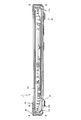
- FIG. 1 is an exploded perspective view of a portable electronic device 1 according to an embodiment of the present invention as viewed from the back side.
- FIG. 2 is a cross-sectional view of ABCD in FIG.
- the portable electronic device 1 includes a device main body 100, a first cover 10 and a second cover 20 that sandwich the device main body 100, and four protective members 31 to 34 that protect corners of the portable electronic device 1. Prepare.
- the device main body 100 is an EOB terminal that has a rectangular plate shape and is used for ordering.
- a display panel 101 is provided on the front side of the device main body 100 (the upper side in FIG. 2 and the lower side in FIG. 1 although not shown in FIG. 1).
- the device main body 100 may be a tablet terminal other than an EOB terminal or a portable electronic device other than a tablet terminal.
- the first cover 10 is located on the front side of the device main body 100.
- the first cover 10 includes a plurality of holding portions 11 (11a to 11g) that hold the device main body 100 so as to hold it.
- the holding portion 11 is, for example, a claw portion, protrudes from the first cover 10 to the back side of the portable electronic device 1, and is curved toward the back surface of the device main body 100 on the tip side so as to hold the device main body 100.
- seven holding units 11 are provided, but the number of holding units 11 may be plural.
- a plurality of locking recesses 12 are provided on the outer peripheral portion of the first cover 10 (upper and lower left and right portions excluding the front and back surfaces).
- the locking convex portion 25 is provided so as to protrude inward from the outer peripheral portion of the second cover 20.
- the locking portion provided in the second cover 20 may be a recess or an opening as in the locking recess 12 instead of the locking protrusion 25. In that case, a convex part will be provided in the 1st cover 10 side.
- the locking projection 25 is provided to position the first cover 10 and the second cover 20 when the second cover 20 is fixed to the device main body 100, for example, and the locking projection 25 It is not provided for attaching the second cover 20 to the apparatus main body 100 only by the above. For this reason, the locking projection 25 and the locking recess 12 into which the locking projection 25 is fitted may be omitted.
- the control unit 13 is disposed on the first cover 10.
- the control unit 13 performs control such as data transmission / reception with respect to the device main body 100 and control of an operation unit (not shown) provided on the first cover 10 on the front side of the control unit 13.
- the first cover 10 is formed larger than the device main body 100 in a plane parallel to the display surface of the display panel 101. .
- the outer peripheral surface of the second cover 20 is located outside the outer peripheral surface of the first cover 10, and the second cover 20 covers the control unit 13 and the device main body 100 of the first cover 10. Therefore, the second cover 20 is also formed larger than the device main body 100 in a plane parallel to the display surface of the display panel 101.
- the first cover 10 and the second cover 20 are substantially the same as the device main body 100 in a plane parallel to the display surface of the display panel 101. It is possible to make it the size of.
- an opening 14 is formed in order to expose the display panel 101 of the device main body 100 to the outside.
- the second cover 20 is located on the back side of the device main body 100.
- the second cover 20 includes fixing screws 21 to 24 that fix the second cover 20 to, for example, four corners of the device main body 100. Further, the second cover 20 holds the above-described plurality of holding portions 11 between the second cover 20 and the device main body 100 as shown in FIG. 2 while being fixed to the device main body 100 by the fixing screws 21 to 24. By holding the plurality of holding portions 11 in this way, the first cover 10 that holds the device main body 100 so as to hold it is also fixed.
- the two fixing screws 23 and 24 are arranged at corners farther from the control unit 13 than the corners at which the other fixing screws 21 and 22 are arranged among the four corners of the device main body 100.
- the fixing screws 21 to 24 are inserted from the back surface of the second cover 20 and extend in the thickness direction of the portable electronic device 1 (vertical direction in FIGS. 1 and 2 which is a direction perpendicular to the display surface of the display panel 101).
- the second cover 20 is fixed to the device main body 100.
- the fixing screws 21 to 24 may be inserted from the outer peripheral surface of the second cover 20 to fix the second cover 20 to the device main body 100 in a direction different from the thickness direction of the portable electronic device 1.
- a plurality of locking projections 25 fitted into the plurality of locking recesses 12 as described above are provided inside the outer peripheral surface of the second cover 20.
- Protective members 31 to 34 protect the corners of the portable electronic device 1.
- the material of the protection members 31 to 34 for example, rubber
- the second cover 20 for example, plastic
- the number of the protective members 31 to 34 is four in order to protect the four corners of the portable electronic device 1, but a single protective member is provided over the two corners so that the two corners are provided. In the case of protection, the number may be two, and is not limited to four.
- the protective members 31 to 34 are located on the back side of the second cover 20, but together with the second cover 20 constitute the back surface and the outer peripheral surface of the portable electronic device 1, and each of the four corners of the portable electronic device 1. Protect the front and back sides. As shown in FIG. 2, the protection members 31 to 34 also function as legs of the portable electronic device 1 when the display surface of the display panel 101 is arranged vertically upward.
- the two protective members 31 and 32 except the protective members 33 and 34 fixed by the fixing screws 23 and 24 are used as the first cover 10 and the second cover 20. It has fixing screws 31a and 32a which are examples of a protection member fixing part which fixes to both of them collectively.
- fixing screws 31 a and 32 a are located outside the device main body 100 so as to sandwich the control unit 13. Therefore, the fixing screws 31a and 32a do not directly fix the device main body 100, but indirectly fix the device main body 100 by fixing the first cover 10, the second cover 20, and the protection members 31 and 32. 100 is fixed.
- the fixing direction of these fixing screws 31a and 32a is the thickness direction of the portable electronic device 1 like the fixing screws 21 to 24, but may be a direction different from the thickness direction of the portable electronic device 1. Good.
- the first cover 10 having the plurality of holding portions 11 is the cover on the front side of the portable electronic device 1
- the second cover 20 having the fixing screws 21 to 24 is the back side of the portable electronic device 1. It is a cover.
- the first cover 10 may be a cover on the back side of the portable electronic device 1
- the second cover 20 may be a cover on the front side of the portable electronic device 1.
- the holding portion 11 is a claw portion.
- the holding portion 11 may be a member that rotates between a position where the device main body 100 is held and a position where the device main body 100 is retracted. If it can hold
- the fixing screws 21 to 24 are given as an example of the second cover fixing part, and the fixing screws 31a and 32a are given as an example of the protective member fixing part. Is not limited to fixing screws.
- a mechanism may be employed in which a lever that penetrates the second cover 20 from the device main body 100 and protrudes to the back side of the second cover 20 is provided, and this lever is rotated to be locked. .
- a lever that protrudes from the first cover 10 through the second cover 20 and the protective members 31, 32 to the back side of the protective members 31, 32 is provided as a protective member fixing portion, and the lever is rotated to lock. You may employ
- the portable electronic device 1 includes the device main body 100, and the first cover 10 and the second cover 20 that sandwich the device main body 100.
- the first cover 10 has a plurality of holding portions 11 that hold the device main body 100 so as to hold it.
- the second cover 20 has fixing screws 21 to 24 which are examples of second cover fixing portions for fixing the second cover 20 to the device main body 100, and is fixed to the device main body 100 by these fixing screws 21 to 24. In this state, a plurality of holding portions 11 are sandwiched between the device main body 100.
- the plurality of holding portions 11 that hold the device main body 100 so as to hold the device main body 100 are sandwiched between the device main body 100 and the second cover 20 fixed to the device main body 100, so that the first cover 10 and The second cover 20 can be firmly attached to the device main body 100.
- the fixing screw used only for firmly fixing the first cover 10 and the second cover 20 to each other can be omitted, the device body 100 around the first cover 10 or the second cover 20 A screw fixing structure such as a boss can be omitted. Thereby, especially in the plane parallel to the display surface of the display panel 101, the enlargement of the portable electronic device 1 can be prevented.
- the portable electronic device 1 can be prevented from being enlarged, and the first cover 10 and the second cover 20 that sandwich the device main body 100 can be firmly attached to the device main body 100. it can.
- the enlargement of the portable electronic device 1 can be prevented, the appearance of the portable electronic device 1 can be prevented from being damaged, the weight of the portable electronic device 1 can be reduced, or the portable electronic device 1 can be reduced. Portability such as ease of holding can be improved.
- the first cover 10 and the second cover 20 can be firmly attached to the apparatus main body 100, the drop impact absorbability and the waterproof performance by the first cover 10 and the second cover 20 can be further improved. it can.
- At least one of the plurality of protection members 31 to 34 (protection members 31 and 32) is used as both the first cover 10 and the second cover 20.
- Fixing screws 31a and 32a which are examples of protective member fixing portions that are fixed together, are provided. Therefore, the first cover 10 and the second cover 20 can be attached to the device main body 100 more firmly by the fixing screws 31 a and 32 a for fixing the protection members 31 and 32.
- At least one of the plurality of protection members 31 to 34 (protection members 33 and 34) is fixed by the fixing screws 23 and 24 for fixing the second cover 20 to the device main body 100.
- the two covers 20 are fixed together with the device main body 100. Therefore, the protection members 33 and 34 can be arranged in the portable electronic device 1 with a simple configuration. Thereby, the enlargement of the portable electronic device 1 can be further prevented.
- the second cover 20 further includes a locking projection 25 that is an example of a locking portion that is fitted in the locking recess 12 and locks the first cover 10. Therefore, the first cover 10 and the second cover 20 can be positioned when the second cover 20 is fixed to the device main body 100, for example.
- an example of the second cover fixing portion is the fixing screws 21 to 24 that fix the second cover 20 to the device main body 100 in the thickness direction of the portable electronic device 1. Therefore, for example, as compared with the case where the second cover 20 is fixed to the device main body 100 in a direction parallel to the display surface of the display panel 101 of the portable electronic device 1, the holding unit 11 can be securely connected to the device main body 100. Can be held between. Alternatively, in particular, the portable electronic device 1 can be further prevented from being enlarged on a plane parallel to the display surface of the display panel 101.
Landscapes
- Engineering & Computer Science (AREA)
- Signal Processing (AREA)
- Microelectronics & Electronic Packaging (AREA)
- Health & Medical Sciences (AREA)
- Public Health (AREA)
- Casings For Electric Apparatus (AREA)
- Telephone Set Structure (AREA)
Abstract
Description
携帯型電子機器1は、機器本体100と、この機器本体100を挟み込む第1カバー10及び第2カバー20と、携帯型電子機器1の角部を保護する4つの保護部材31~34と、を備える。
10 第1カバー
11(11a~11g) 保持部
12 係止用凹部
13 制御部
14 開口部
20 第2カバー
21~24 固定ネジ
25 係止凸部
31~34 保護部材
31a,31b 固定ネジ
100 機器本体
101 表示パネル
Claims (6)
- 機器本体と、
前記機器本体を挟み込む第1カバー及び第2カバーと、を備え、
前記第1カバーは、前記機器本体を抱え込むように保持する複数の保持部を有し、
前記第2カバーは、該第2カバーを前記機器本体に対し固定する第2カバー固定部を有し、該第2カバー固定部によって前記機器本体に対し固定された状態で該機器本体との間に前記複数の保持部を挟持する、
ことを特徴とする携帯型電子機器。 - 前記携帯型電子機器の角部を保護する複数の保護部材を更に備え、
前記複数の保護部材のうちの少なくとも1つは、該保護部材を前記第1カバー及び前記第2カバーの両方に対し一括して固定する保護部材固定部を有する、
ことを特徴とする請求項1記載の携帯型電子機器。 - 前記携帯型電子機器の角部を保護する複数の保護部材を更に備え、
前記複数の保護部材のうちの少なくとも1つは、前記第2カバー固定部によって前記第2カバーとともに前記機器本体に対し固定される、
ことを特徴とする請求項1記載の携帯型電子機器。 - 前記携帯型電子機器の角部を保護する複数の保護部材を更に備え、
前記複数の保護部材のうちの一部の保護部材は、該保護部材を前記第1カバー及び前記第2カバーの両方に対し一括して固定する保護部材固定部を有し、
前記複数の保護部材のうちの他の一部の保護部材は、前記第2カバー固定部によって前記第2カバーとともに前記機器本体に対し固定される、
ことを特徴とする請求項1記載の携帯型電子機器。 - 前記第2カバーは、前記第1カバーを係止する係止部を更に有することを特徴とする請求項1記載の携帯型電子機器。
- 前記第2カバー固定部は、前記携帯型電子機器の厚み方向に、前記第2カバーを前記機器本体に対し固定する固定ネジであることを特徴とする請求項1記載の携帯型電子機器。
Priority Applications (4)
| Application Number | Priority Date | Filing Date | Title |
|---|---|---|---|
| PCT/JP2014/084722 WO2016103524A1 (ja) | 2014-12-27 | 2014-12-27 | 携帯型電子機器 |
| KR1020177011022A KR102052253B1 (ko) | 2014-12-27 | 2014-12-27 | 휴대형 전자 기기 |
| JP2016565858A JP6259127B2 (ja) | 2014-12-27 | 2014-12-27 | 携帯型電子機器 |
| TW104138079A TWI580335B (zh) | 2014-12-27 | 2015-11-18 | Portable electronic machine |
Applications Claiming Priority (1)
| Application Number | Priority Date | Filing Date | Title |
|---|---|---|---|
| PCT/JP2014/084722 WO2016103524A1 (ja) | 2014-12-27 | 2014-12-27 | 携帯型電子機器 |
Publications (1)
| Publication Number | Publication Date |
|---|---|
| WO2016103524A1 true WO2016103524A1 (ja) | 2016-06-30 |
Family
ID=56149606
Family Applications (1)
| Application Number | Title | Priority Date | Filing Date |
|---|---|---|---|
| PCT/JP2014/084722 Ceased WO2016103524A1 (ja) | 2014-12-27 | 2014-12-27 | 携帯型電子機器 |
Country Status (4)
| Country | Link |
|---|---|
| JP (1) | JP6259127B2 (ja) |
| KR (1) | KR102052253B1 (ja) |
| TW (1) | TWI580335B (ja) |
| WO (1) | WO2016103524A1 (ja) |
Cited By (1)
| Publication number | Priority date | Publication date | Assignee | Title |
|---|---|---|---|---|
| JP2021052330A (ja) * | 2019-09-25 | 2021-04-01 | 富士通クライアントコンピューティング株式会社 | 電子機器 |
Families Citing this family (1)
| Publication number | Priority date | Publication date | Assignee | Title |
|---|---|---|---|---|
| KR102272176B1 (ko) * | 2020-10-15 | 2021-07-05 | 카페24 주식회사 | 충격 방지를 위한 휴대용 모바일 단말 장치 |
Citations (2)
| Publication number | Priority date | Publication date | Assignee | Title |
|---|---|---|---|---|
| JP2007235825A (ja) * | 2006-03-03 | 2007-09-13 | Sharp Corp | 携帯電子機器 |
| JP2014117483A (ja) * | 2012-12-17 | 2014-06-30 | Yamaichi Kicho Co Ltd | 携帯電話機用カバー |
Family Cites Families (11)
| Publication number | Priority date | Publication date | Assignee | Title |
|---|---|---|---|---|
| KR100790136B1 (ko) * | 2006-12-08 | 2008-01-02 | 삼성전자주식회사 | 경사진 결속 돌기를 구비하는 휴대용 단말기 |
| KR100810266B1 (ko) * | 2006-12-14 | 2008-03-06 | 삼성전자주식회사 | 보강 부재를 구비하는 휴대용 단말기 |
| JP4538013B2 (ja) | 2007-02-22 | 2010-09-08 | 株式会社東芝 | 携帯端末の保護ケース |
| JP4974151B2 (ja) | 2007-02-27 | 2012-07-11 | 京セラディスプレイ株式会社 | 表示装置収納ケース |
| TW201010567A (en) * | 2008-08-26 | 2010-03-01 | Eimo Technology Co Ltd | Protective casing for electronic device |
| TWI374000B (en) * | 2009-06-10 | 2012-10-01 | King Slide Works Co Ltd | Housing assembly for an electrical device |
| JP2012182200A (ja) * | 2011-02-28 | 2012-09-20 | Asahi:Kk | 電子機器用の防水ケース |
| KR101943315B1 (ko) * | 2011-12-07 | 2019-01-29 | 엘지전자 주식회사 | 이동 단말기 및 이동 단말기의 체결방법 |
| KR20130085218A (ko) * | 2012-01-19 | 2013-07-29 | 엘지전자 주식회사 | 이동 단말기 |
| TWM435145U (en) * | 2012-02-03 | 2012-08-01 | Kentec Inc | Multimedia player protection cover |
| US8955678B2 (en) | 2013-03-14 | 2015-02-17 | Pelican Products, Inc. | Protective cases for mobile electronic communication devices |
-
2014
- 2014-12-27 KR KR1020177011022A patent/KR102052253B1/ko active Active
- 2014-12-27 WO PCT/JP2014/084722 patent/WO2016103524A1/ja not_active Ceased
- 2014-12-27 JP JP2016565858A patent/JP6259127B2/ja active Active
-
2015
- 2015-11-18 TW TW104138079A patent/TWI580335B/zh active
Patent Citations (2)
| Publication number | Priority date | Publication date | Assignee | Title |
|---|---|---|---|---|
| JP2007235825A (ja) * | 2006-03-03 | 2007-09-13 | Sharp Corp | 携帯電子機器 |
| JP2014117483A (ja) * | 2012-12-17 | 2014-06-30 | Yamaichi Kicho Co Ltd | 携帯電話機用カバー |
Cited By (2)
| Publication number | Priority date | Publication date | Assignee | Title |
|---|---|---|---|---|
| JP2021052330A (ja) * | 2019-09-25 | 2021-04-01 | 富士通クライアントコンピューティング株式会社 | 電子機器 |
| US11600900B2 (en) | 2019-09-25 | 2023-03-07 | Fujitsu Client Computing Limited | Electronic device |
Also Published As
| Publication number | Publication date |
|---|---|
| JP6259127B2 (ja) | 2018-01-10 |
| KR102052253B1 (ko) | 2019-12-04 |
| TWI580335B (zh) | 2017-04-21 |
| TW201630504A (zh) | 2016-08-16 |
| KR20170063789A (ko) | 2017-06-08 |
| JPWO2016103524A1 (ja) | 2017-06-01 |
Similar Documents
| Publication | Publication Date | Title |
|---|---|---|
| JP3198689U (ja) | 保護カバー | |
| US9038979B2 (en) | Multifunctional case for portable electronic device | |
| US8573395B1 (en) | Electronic device protection assembly | |
| US9137918B2 (en) | Electronic apparatus and method for assembling the same | |
| KR20140143262A (ko) | 전자 기기용 케이스 | |
| CN105849666B (zh) | 电子设备 | |
| JP4549368B2 (ja) | 係止フック構造 | |
| US10019046B2 (en) | Internal frame structure with heat insulation effect and electronic apparatus with the internal frame structure | |
| JP5421449B1 (ja) | 携帯端末装置 | |
| KR20130121297A (ko) | 디스플레이 장치의 파손 방지 구조를 구비하는 휴대용 단말기 | |
| US20130250509A1 (en) | Electronic device | |
| WO2013108312A1 (ja) | 携帯端末装置 | |
| JPWO2013108311A1 (ja) | 携帯端末装置 | |
| JP2014048362A (ja) | テレビジョン受像機および電子機器 | |
| CN110896654A (zh) | 运动相机和具体该运动相机的手持设备 | |
| TWM499807U (zh) | 保護殼 | |
| JP6512488B2 (ja) | 携帯機器 | |
| JP6259127B2 (ja) | 携帯型電子機器 | |
| JP2007034939A (ja) | 電子機器 | |
| WO2021215102A1 (ja) | 携帯端末 | |
| CN107817873B (zh) | 便携设备 | |
| JP6786924B2 (ja) | 携帯端末 | |
| TWM463855U (zh) | 電子產品之保護殼結構 | |
| JP6507275B2 (ja) | 電子機器 | |
| US20140177140A1 (en) | Electronic device assembly |
Legal Events
| Date | Code | Title | Description |
|---|---|---|---|
| 121 | Ep: the epo has been informed by wipo that ep was designated in this application |
Ref document number: 14909125 Country of ref document: EP Kind code of ref document: A1 |
|
| ENP | Entry into the national phase |
Ref document number: 2016565858 Country of ref document: JP Kind code of ref document: A |
|
| ENP | Entry into the national phase |
Ref document number: 20177011022 Country of ref document: KR Kind code of ref document: A |
|
| NENP | Non-entry into the national phase |
Ref country code: DE |
|
| 122 | Ep: pct application non-entry in european phase |
Ref document number: 14909125 Country of ref document: EP Kind code of ref document: A1 |