WO2016103407A1 - V型エンジン - Google Patents
V型エンジン Download PDFInfo
- Publication number
- WO2016103407A1 WO2016103407A1 PCT/JP2014/084347 JP2014084347W WO2016103407A1 WO 2016103407 A1 WO2016103407 A1 WO 2016103407A1 JP 2014084347 W JP2014084347 W JP 2014084347W WO 2016103407 A1 WO2016103407 A1 WO 2016103407A1
- Authority
- WO
- WIPO (PCT)
- Prior art keywords
- bank
- passage
- side intake
- injection device
- intake passage
- Prior art date
- Legal status (The legal status is an assumption and is not a legal conclusion. Google has not performed a legal analysis and makes no representation as to the accuracy of the status listed.)
- Ceased
Links
Images



Classifications
-
- F—MECHANICAL ENGINEERING; LIGHTING; HEATING; WEAPONS; BLASTING
- F02—COMBUSTION ENGINES; HOT-GAS OR COMBUSTION-PRODUCT ENGINE PLANTS
- F02M—SUPPLYING COMBUSTION ENGINES IN GENERAL WITH COMBUSTIBLE MIXTURES OR CONSTITUENTS THEREOF
- F02M35/00—Combustion-air cleaners, air intakes, intake silencers, or induction systems specially adapted for, or arranged on, internal-combustion engines
- F02M35/10—Air intakes; Induction systems
- F02M35/104—Intake manifolds
- F02M35/116—Intake manifolds for engines with cylinders in V-arrangement or arranged oppositely relative to the main shaft
-
- F—MECHANICAL ENGINEERING; LIGHTING; HEATING; WEAPONS; BLASTING
- F02—COMBUSTION ENGINES; HOT-GAS OR COMBUSTION-PRODUCT ENGINE PLANTS
- F02M—SUPPLYING COMBUSTION ENGINES IN GENERAL WITH COMBUSTIBLE MIXTURES OR CONSTITUENTS THEREOF
- F02M63/00—Other fuel-injection apparatus having pertinent characteristics not provided for in groups F02M39/00 - F02M57/00 or F02M67/00; Details, component parts, or accessories of fuel-injection apparatus, not provided for in, or of interest apart from, the apparatus of groups F02M39/00 - F02M61/00 or F02M67/00; Combination of fuel pump with other devices, e.g. lubricating oil pump
-
- F—MECHANICAL ENGINEERING; LIGHTING; HEATING; WEAPONS; BLASTING
- F02—COMBUSTION ENGINES; HOT-GAS OR COMBUSTION-PRODUCT ENGINE PLANTS
- F02M—SUPPLYING COMBUSTION ENGINES IN GENERAL WITH COMBUSTIBLE MIXTURES OR CONSTITUENTS THEREOF
- F02M69/00—Low-pressure fuel-injection apparatus ; Apparatus with both continuous and intermittent injection; Apparatus injecting different types of fuel
- F02M69/04—Injectors peculiar thereto
Definitions
- the present disclosure relates to V-engines.
- Patent Document 1 discloses a V-type engine having two types of injectors.
- the V-type engine of Patent Document 1 includes, for each cylinder, an injector (in-cylinder injector) that directly injects fuel into the combustion chamber and an injector (intake pipe injector) that injects fuel into the intake passage.
- the intake port of each bank of the V-type engine opens into the bank, and the intake manifold (intake manifold) is provided from a surge tank provided at the top of one bank (left bank) to both banks.
- An intake manifold extends to each intake port.
- the intake pipe injector is provided outside the intake manifold, and the in-cylinder injector is provided inside the intake manifold.
- the intake pipe injector of Patent Document 1 is provided in a narrow space between the in-manifold and the respective banks located on the outside thereof. Therefore, the installation angle of the intake pipe injector is limited by the manifold and the bank, and it may be difficult to install the intake pipe injector so as to have a desired angle. In addition, since the installation space of the intake pipe injector is narrow in this way, the work of attaching the intake pipe injector becomes more difficult than when the installation space is wider, and the work procedure for installing the intake pipe injector is also Limited And such a concern becomes remarkable as the engine is miniaturized.
- At least one embodiment of the present invention aims to provide a V-type engine capable of increasing the degree of freedom of the installation area and the installation angle of the intake passage injection device.
- a V-type engine is a V-type engine including a pair of banks consisting of a first bank and a second bank, wherein the V-type engine is opened between the pair of banks A plurality of first side intake ports of one bank, a plurality of second side intake ports of the second bank opened respectively between the pair of banks, and a pair of first side intake ports are connected.
- a first manifold passage portion comprising a plurality of branch passages extending upward along the first bank from between the banks of the second bank and the second side intake port, and the second manifold passage from the pair of banks
- the fuel injection system according to the present invention is configured to inject fuel into a second manifold including a plurality of branch channels extending upward along the bank, and the first inlet including the first side intake port and the first manifold.
- a second side intake path injection device configured to inject fuel into a second side intake path including the second side intake port and the second manifold passage portion, the first side
- the intake passage injection device is disposed between the first side intake passage and the second side intake passage on a first side projection portion which is a portion of the first side intake passage that most protrudes toward the second bank.
- the second side intake passage injection device is provided between the first side intake passage and the second side intake passage at a portion that protrudes most toward the first bank of the second side intake passage. It is provided at a second side projection.
- each of the intake passage injectors of the first bank and the second bank (the first side intake passage injectors and the second side intake passage injectors) is between the pair of banks (banks In the bank space such as the inner space and the upper space (between the banks) in the bank, it is provided at the most projecting portion (first side protruding portion, second side protruding portion).
- This can increase the degree of freedom of the installation area and the installation angle of the intake passage injection device. Therefore, fuel injection can be easily realized at a preferable injection angle, and fuel consumption can be improved.
- the intake passage injection device includes an intake passage (first side intake passage) including an intake port (first side intake port, second side intake port) and a manifold passage portion (first manifold passage portion, second manifold passage portion).
- the second side intake passage The first bank, the second bank, and the manifold passage function as a protective wall, and the protective wall can protect the intake passage injection device.
- the opening of the first side intake port and the opening of the second side intake port face upward.
- the manifold passage extending upward along the side surface of each of the first bank and the second bank is connected to the intake port opening upward, so the cylinder head has a protrusion It includes an intake port formed in Therefore, since the intake passage injection device can be fixed to the cylinder head, the installation stability of the intake passage injection device can be enhanced, and the reliability of the V-type engine can be enhanced.
- the first side protruding portion connects the opening of the first side intake port and the opening of the first manifold passage portion.
- the second side protrusion is a connection portion where the opening of the second side intake port and the opening of the second manifold passage portion are connected.
- a first side in-cylinder injection device configured to inject fuel directly, and provided between the pair of banks below the second side intake passage injection device, and directly injects the fuel into the combustion chamber of the second bank
- a second in-cylinder injector configured to:
- the axis of the cylinder formed in each of the pair of banks is the same direction as the crankshaft rotation direction with respect to the crankshaft center Offset to According to the configuration of the above (5), by utilizing the height difference between the pair of banks caused by the above offset, the intake passages of the first bank and the second bank are prevented without causing mutual interference such as collision with each other.
- An injector (a first side intake passage injector, a second side intake passage injector) can be installed in the bank space.
- the first side intake passage injection device and the second side intake passage injection device are disposed mutually offset in the front-rear direction Ru. According to the configuration of the above (6), even when the pinch angle (bank angle) of the pair of banks is narrow, the one-side intake passage injector and the two-side intake passage injector can be arranged in the bank space .
- a V-type engine is provided in which the installation area and the installation angle of the intake passage injection device are increased.
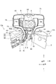
- FIG. 1 is a front view of a V-type engine according to an embodiment of the present invention.
- FIG. 2 is a partial cross-sectional view of the V-type engine in FIG.
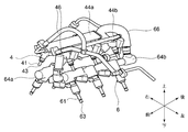
- FIG. 2 is a side view of a portion above the cylinder head portion of the V-type engine in FIG. 1; It is a perspective view of an intake passage injection device concerning one embodiment of the present invention.
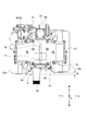
- FIG. 5 is a side view of the intake passage injector of FIG. 4; It is a top view of V-type engine of FIG.
- expressions that indicate that things such as “identical”, “equal” and “homogeneous” are equal states not only represent strictly equal states, but also have tolerances or differences with which the same function can be obtained. It also represents the existing state.
- expressions representing shapes such as quadrilateral shapes and cylindrical shapes not only represent shapes such as rectangular shapes and cylindrical shapes in a geometrically strict sense, but also uneven portions and chamfers within the range where the same effect can be obtained. The shape including a part etc. shall also be expressed.
- the expressions “comprising”, “having”, “having”, “including” or “having” one component are not exclusive expressions excluding the presence of other components.
- FIG. 1 is a front view of a V-type engine 1 according to an embodiment of the present invention.
- FIG. 2 is a partial cross-sectional view of the V-type engine in FIG.
- FIG. 3 is a side view of a portion above the cylinder head portion 3 of the V-type engine 1 in FIG.
- FIG. 4 is a perspective view of an intake manifold injector 4 in some embodiments.
- FIG. 5 is a side view of the intake passage injector 4 of FIG. 6 is a plan view of the V-type engine of FIG.
- the V-type engine 1 (hereinafter referred to as the engine 1) includes an intake port 32 (a first side intake port 32a and a second side intake port 32b) and a manifold passage 52 (a first manifold).
- a passage portion 52a, a second manifold passage portion 52b, and an intake passage injection device 4 (a first side intake passage injection device 4a, a second side intake passage injection device 4b) are provided.
- the engine 1 is a six-cylinder V-type engine in the example of FIG. 1, and has a first bank 12a (right bank in FIG. 1) and a second bank 12b each having three cylinders 23 (cylinders) arranged in series. (The left bank in FIG. 1) is arranged in a V-shape (V-shape), and both banks (12a, 12b) share one crankshaft 15.
- the engine body 11 of the engine 1 is composed of a V-shaped cylinder block portion 2 and a cylinder head portion 3.
- the cylinder block portion 2 has a V-shaped deck cylinder portion 21 and a crankcase portion 22 common to both banks (12 a and 12 b) provided at the lower part of the deck cylinder portion 21.
- the upper deck surface 26 which is a surface on which the cylinder head portion is mounted is provided on both V-shaped head portions of the deck cylinder portion 21, and a plurality of the above-described plurality are provided inside the deck cylinder portion 21.
- a cylinder 23 is provided. Further, a crank shaft 15 is rotatably supported by the above-described crankcase portion 22.
- a piston 24 slidably accommodated in each cylinder 23 is connected to the crankshaft 15 via a connecting rod 25.
- crankshaft 15 rotates in the direction indicated by the arrow E that is clockwise around the axis center O of the crankshaft 15.
- the cylinder block portion 2 may also include an oil pan 28 mounted so as to cover the lower opening of the crankcase portion 22.
- a plurality of depressions (for example, a hemispherical shape or the like) positioned so as to correspond to each of the plurality of cylinders 23 are provided. Then, when the cylinder head portion 3 is mounted on the upper deck surface 26 of the deck cylinder portion 21, the plurality of cylinders 23 inside the deck cylinder portion 21 and the above-mentioned plurality of depressions respectively coincide with each other, thereby burning each cylinder 23.
- a chamber 31 is formed. Further, by mounting the cylinder head portion 3 on the deck cylinder portion 21, a pair of banks 12 of the first bank 12a and the second bank 12b is formed.
- the cylinder head portion 3 may include a rocker cover 37 mounted so as to close the head opening of each cylinder head portion 3 of each bank 12.
- two intake and exhaust valves (not shown), an intake port 32 (described later) opened in the bank 13, and an exhaust port 35 are provided for each cylinder 23. . That is, the combustion chamber 31 of each cylinder 23 and the outside of the cylinder head portion 3 are respectively communicated by the intake port 32 (32a, 32b) which is a passage for guiding intake air to the combustion chamber 31. Configured to be controlled.
- an exhaust port 35 which is a passage for guiding the combustion gas (exhaust gas) from the combustion chamber 31 to the outside, also communicates each combustion chamber 31 with the outside of each bank 12, and this communication state is controlled by the exhaust valve.
- the exhaust ports 35 may communicate with the respective combustion chambers 31 by extending to other than the inside of the bank 13 such as the side opposite to the inside of the bank 13 where the intake port 32 is provided. Further, the intake port 32 and the exhaust port 35 are branched into two inside each and connected to the combustion chamber 31, and one intake valve and one exhaust valve are provided for each branch.
- the sandwich angle (bank angle) formed by the two banks 12 of the first bank 12a and the second bank 12b is about 60 degrees, and the space formed in the bank 13 has a bank angle of 90 ° C. It is narrower than things.
- the bank angle is not limited to 60 degrees, but may be any angle such as 90 degrees.
- the supercharger 8 may be provided between the banks, which is a space that extends above (above) the inside of the bank 13 in the vertical direction (hereinafter, the vertical direction) of the engine body 11.
- the number of cylinders of the engine 1 is not limited to six, and may be a multi-cylinder engine having a plurality of cylinders.
- the number of intake and exhaust valves for each cylinder 23 is also arbitrary, and may be one or more, and the number of branches inside the intake port 32 and the exhaust port 35 is also an intake valve and an exhaust port. It corresponds to the number of valves.
- the intake port 32 includes a plurality of first side intake ports 32 a of the first bank 12 a that opens between the pair of banks 12 and a plurality of second side of the second banks 12 b that opens between the pair of banks 12. And a side intake port 32b. That is, as illustrated in FIG. 1, a plurality (three in FIG. 1) of intake ports 32 (first side intake ports 32 a) are provided in the first bank 12 a and each opens in the bank 13. Similarly, a plurality (three in FIG. 1) of intake ports 32 (second side intake ports 32b) are provided in the second bank 12b, and they are opened in the bank 13 respectively.
- the intake port 32 is configured to be connected (connected) to a manifold passage portion 52 (intake manifold) that constitutes a part of an intake passage that supplies air to the combustion chamber 31.
- the intake air (intake air) flowing through the intake passage is supplied to the intake port 32 from the manifold passage 52 located on the upstream side.
- the opening 33 of the intake port 32 is configured to be connectable to the manifold passage portion 52, and is also configured to be able to connect the tip end portion 41 of the intake passage injection device 4 described later.
- the opening 33 of the intake port 32 has such a base shape so that the tip end portion 41 of the intake path injection device 4 can be inserted (connected) on the basis of a shape conforming to the shape of the internal passage of the manifold passage portion 52 You may form so that one part may be spread (refer FIG. 3).
- the manifold passage portion 52 is connected to each of the first side intake ports 32a, and includes a plurality of first manifold passage portions 52a each including a plurality of branch passages 53 extending upward from the pair of banks 12 along the first bank 12a. And a second manifold passage portion 52b formed of a plurality of branch passages 53 connected to the second side intake ports 32b and extending upward from the pair of banks 12 along the second bank 12b.
- the first manifold passage portion 52a (a plurality of branch passages 53) extends from the opening 33 of the first side intake port 32a of the first bank 12a to the side surface of the first bank 12a forming the inside 13 of the bank.
- the second manifold passage portion 52 b (plural branch passages 53) extends from the opening 33 of the second side intake port 32 b of the second bank 12 b along the side surface of the second bank 12 b forming the inside 13 of the bank It extends upward in the bank 13 without contacting the second bank 12b.
- the first manifold passage 52 a is a front branch located on the front side (front side) of the engine body 11 in the front-rear direction (hereinafter, “front-rear direction”).
- the branch passages 53 (63f, 63c, 63r) of the first manifold passage 52a are respectively connected to the three first side intake ports 32a of the first bank 12a while forming independent intake passages therein. It is done.
- the second manifold passage 52b has a front branch passage 53f, a central branch passage 53c and a rear branch passage 53r, and each branch passage 53 of the second manifold passage 52b (not shown) 63f, 63c, 63r) are respectively connected to the three second side intake ports 32b of the second bank 12b while forming independent intake passages therein.
- each branch passage 53 included in the first manifold passage 52a and the second manifold passage 52b is connected to each intake port 32, and the other end (upstream end) is the other intake
- the manifold passage portion 52 forms a part of an intake passage for introducing air (fresh air) from the outside of the engine 1 to the combustion chambers 31 inside. That is, the first side intake passage 5a is formed by the first side intake port 32a and the first manifold passage portion 52a. Further, the second side intake passage 5b is formed by the second side intake port 32b and the second manifold passage portion 52b.
- Each of the first side intake passage 5a and the second side intake passage 5b has a portion (protruding portion 51) that protrudes most toward the bank space in each shape. More specifically, as illustrated in FIG. 1, the first manifold portion 52a forming the first side intake passage 5a extends upward along the side surface of the first bank 12a, and the second side intake passage 5b The second manifold passage 52b to be formed extends upward along the side surface of the second bank 12b. Therefore, the first manifold passage portion 52a and the second manifold passage portion 52b are located outside the engine main body 11 at the upper portion (upstream side in the flow direction of the intake air) than the connecting portion 54 with the opening 33 of the intake port 32.
- the manifold passage 52 is connected to the opening 33 of the intake port at such a position and extends upward along each bank 12, so that the first side intake passage 5a and the second side intake passage 5b A shape (protruding portion 51) protruding toward the other bank 12 side is formed on the side wall.
- the central axis of the intake port 32a is directed to the inside of the bank 13 in a front view of the engine 1 ( Toward the second bank 12b).
- the central axis of each branch passage 53 constituting the first manifold passage portion 52a in the front view of the engine 1 is obliquely downward toward the inside of the bank 13 (to the second bank 12b) Are oriented.
- the projection 51 is connected by connecting the opening 33 of the intake port 32a and the opening of the first manifold passage 52a at the intersection of the center axis of the intake port 32a and the center shaft of the first manifold passage 52a. It is formed.
- a similar shape is also formed on the second bank 12b side. That is, in the intake port 32b of the second bank 12b, the center axis of the intake port 32b in the front view of the engine 1 is directed obliquely upward toward the in-bank 13 (to the first bank 12a).
- the central axis of each branch passage 53 constituting the second manifold passage 52b in the front view of the engine 1 is directed obliquely downward toward the inside of the bank 13 (toward the first bank 12a).
- the opening 51 of the intake port 32b and the opening of the second manifold passage 52b are connected at the intersection of the center axis of the intake port 32b and the center shaft of the second manifold passage 52b, whereby the protrusion 51 is formed. It is formed.
- the first side intake passage 5a connected to the first bank 12a has a shape projecting toward the second bank 12b
- the second side intake passage 5b connected to the second bank 12b is the second It has a shape projecting to the side of one bank 12a.
- the intake path injection device 4 is provided on the projecting portion 51.
- the intake passage injection device 4 will be described.
- the intake passage injection device 4 is configured to receive fuel into the first side intake passage 5a (the first side intake passage 5a consisting of the first side intake port 32a and the first manifold passage 52a).
- the fuel is supplied to the first side intake passage injector 4a configured to inject and the second side intake passage 5b (the second side intake passage 5b including the second side intake port 32b and the second manifold passage portion 52b).
- a second side intake path injector configured to inject.
- the fuel injection port 43 for injecting fuel by the tip 41 of the intake passage injector 4 extending to the inside of the intake port 32 is an intake port. It may be located inside 32 and configured to inject fuel into the intake port 32 thereby.
- the intake passage injection device 4 is provided between the first manifold passage 52a and the second manifold passage 52b as illustrated in FIG. Also good.
- a low pressure fuel supply pipe 44 is connected to the intake passage injection device 4, and fuel (low pressure fuel) is supplied in a low pressure state from a fuel tank (not shown) via the low pressure fuel supply pipe 44 and the fuel pipe 46. Be done. That is, the fuel supplied through the fuel pipe 46 is temporarily supplied to the low pressure fuel supply pipe 44 for each bank 12, and the low pressure fuel supply pipe 44 causes the respective intake passage injectors 4 (in the example of FIG. 3) for each bank 12). As shown in FIG. 2, the fixing member 45 may be used to fix the manifold passage 52.
- the first side low pressure fuel supply pipe 44a for the first bank 12a and the second side low pressure fuel supply pipe 44b for the second bank 12b A plurality of intake passage injectors 4 are connected to one another (three in FIGS. 1 to 4). That is, the first low-pressure fuel supply pipe 44a and the second low-pressure fuel supply pipe 44b have a long shape in the front-rear direction in accordance with the shape of the bank 12. And in order to supply fuel to the combustion chamber 31 of each cylinder 23 which each bank 12 has, a plurality of intake passage injection devices 4 are provided in the first side low pressure fuel supply pipe 44a and the second side low pressure fuel supply pipe 44b. Each is linked.
- the fuel pipe 46 may be connected to one longitudinal end (the forward direction in the front and rear direction in the example of FIG. 4) of each low pressure fuel supply pipe 44 (44a, 44b).
- the two fuel pipes 46 to be combined may be connected upstream to a fuel pump (not shown) after being merged into one.
- the first side intake passage injection device 4a and the second side intake passage injection device 4b are respectively provided in the projecting portion 51 of the first side intake passage 5a and the second side intake passage 5b. That is, the first side intake passage injection device 4a is a portion that protrudes most toward the second bank of the first side intake passage 5a between the first side intake passage 5a and the second side intake passage 5b.
- the second side intake passage injection device is provided in the first side projecting portion 51a, and the second side intake passage injection device is configured to set the first side of the second side intake passage 5b between the first side intake passage 5a and the second side intake passage 5b. It is provided in the 2nd side projection part 51b which is a portion which protrudes most to the bank side.
- the tip end portion 41 of the intake path injection device 4 is inserted into the opening 33 of the intake port 32 opening upward.
- the fuel injection port 43 of the intake passage injection device 4 is located inside the intake port 32.
- the intake passage injection device 4 is configured to inject the fuel into the intake passage (first side intake passage, second side intake passage).
- first manifold passage portion 52a and the second manifold passage portion 52b extend upward along the banks 12, respectively, whereby a bank space consisting of the inside of the banks 13 and between the banks is formed widely. . Since the intake path injection device 4 is provided in such a bank space, there are few obstacles when installing the intake path injection device 4, and it becomes possible to install the intake path injection device 4 at various angles. . Furthermore, the two banks 12 are positioned on the outer periphery in the left-right direction of the intake path injection device 4, and the first manifold passage 52a and the second manifold passage 52b are positioned, and these function as protective walls. It will be.
- each of the intake passage injectors 4 (the first side intake passage injector 4 a and the second side intake passage injector 4 b) of the first bank 12 a and the second bank 12 b is a pair of banks 12.
- the bank space such as the space (within the bank 13) and the space above the inside of the bank 13 (between the banks), they are provided in the most projecting portions (first side protrusion 51a and second side protrusion 51b).
- the intake passage injection device 4 includes an intake port 32 (a first side intake port 32a, a second side intake port 32b) and a manifold passage portion 52 (a first manifold passage portion 52a, a second manifold passage portion 52b). It is provided inside the passage 5 (the first side intake passage 5a and the second side intake passage 5b). Therefore, the first bank 12a, the second bank 12b, and the manifold passage 52 function as a protective wall, and the protective wall can protect the intake passage injection device 4.
- the opening 33 of the first side intake port 32a and the opening 33 of the second side intake port 32b face upward. That is, when the opening 33 of the intake port 32 is directed upward, the protrusion 51 includes the cylinder head portion 3 in which the opening 33 of the intake port 32 is formed. Therefore, the intake path injection device 4 can be installed in the cylinder head portion 3. For example, as described above, by widening the opening 33 of the intake port 32 provided in the cylinder head 3 to a part of the base shape, the distal end of the intake passage injector 4 can be inserted, You may provide in the cylinder head part 3. FIG.
- the intake passage injection device 4 can be fixed to the intake port 32 formed in the cylinder head portion 3, the installation stability of the intake passage injection device 4 can be enhanced. The reliability of the engine 1 can be improved.
- the opening 33 of the intake port 32 may not face upward, and the protrusion 51 may be formed in the manifold passage 52 or the cylinder head 3. Therefore, the intake passage injection device 4 is provided in the manifold passage portion 52 and the cylinder head portion 3.
- the first side protrusion 51 a may be connected such that the opening 33 of the first side intake port 32 a and the opening of the first manifold passage 52 a are connected.
- the second side protruding portion 51b is a connecting portion 54 in which the opening 33 of the second side intake port 32b and the opening of the second manifold passage portion 52b are connected.
- the opening 33 of the intake port 32 may not face upward, and the protrusion 51 may be formed in the manifold passage 52 or the cylinder head 3. Therefore, the intake passage injection device 4 is provided in the manifold passage portion 52 and the cylinder head portion 3.
- FIG. 1 it is provided below the first side intake passage injection device 4a between the pair of banks 12 and in the combustion chamber 31 of the first bank 12a. It is provided below the second side intake passage injection device 4b between the pair of banks 12 with the first side in-cylinder injection device 6a configured to inject fuel directly, and in the combustion chamber 31 of the second bank 12b. And a second side in-cylinder injection device 6b configured to inject fuel directly.
- the cylinder head portion 3 is configured such that the in-cylinder injection device 6 can be inserted from the side that forms the inside 13 of the bank, and the fuel injection port of the in-cylinder injection device 6 to be inserted 63 is configured to face the combustion chamber 31.
- the tip 61 of the in-cylinder injection device 6 inserted into the cylinder head 3 extends toward the combustion chamber 31 so that the fuel injection port 63 at the tip of the tip 61 opens to the combustion chamber 31. It is configured to Further, as shown in FIG. 2, the in-cylinder injection device 6 (tip portion 61) may be installed inside the cylinder head portion 3 along the intake port 32.
- a high pressure fuel supply chamber 64 pressure accumulation chamber is connected to the in-cylinder injection device 6, and fuel in a high pressure state from a fuel tank (not shown) via the high pressure fuel supply chamber 64 and a supply pump (not shown).
- (High-pressure fuel) is supplied.
- fuel in the fuel tank is supplied to the high pressure fuel supply chamber 64 by a supply pump (not shown), and fuel is supplied from the supply pump to the high pressure fuel supply chamber 64 at a predetermined pressure according to the rotational speed of the engine 1 Also good.
- the fuel may be adjusted to a predetermined fuel pressure in the high pressure fuel supply chamber 64, and the high pressure fuel controlled to the predetermined fuel pressure may be supplied from the high pressure fuel supply chamber 64 to the in-cylinder injection device 6.
- high pressure and the low pressure used in the description of the intake passage injection device 4 and the in-cylinder injection device 6 mean relative pressures when the two are compared.
- high pressure fuel means higher pressure than low pressure fuel
- low pressure fuel means lower pressure than high pressure fuel.
- the intake path injection device 4 and the in-cylinder injection device 6 are provided in the V-type engine 1, it is possible to perform the fuel injection suitable for the operation situation. Further, since the in-cylinder injection device 6 is provided in the bank 13, the in-cylinder injection device 6 can be protected by the protective walls of both banks 12 as in the intake passage injection device 4.
- the engine 1 is an axis of a cylinder 23 (cylinder) formed in each of a pair of banks 12 consisting of a first bank 12 a and a second bank 12 b.
- the axis L) is offset in the same direction as the rotational direction of the crankshaft 15 (the direction of the arrow E) with respect to the crankshaft center (axial center O of the crankshaft 15).
- each deck cylinder is maintained while maintaining the length (deck height H) from the axial center O of the crankshaft 15 to the upper deck surface 26 of the cylinder block portion 2.
- the plurality of cylinder axis lines L of the portion 21 are moved in parallel (offset) in the same direction as the rotational direction E of the crankshaft 15 with respect to the axial center O of the crankshaft 15 by the offset amount ⁇ . Note that, in FIG. 1, the plurality of cylinder axis lines L and the plurality of cylinder axis lines L ⁇ b> 1 are each shown to overlap with the one on the front side.
- the offset causes the first bank 12a on the front side in the rotational direction E to be higher than the position of the normal engine, and the second bank 12b on the rear side in the rotational direction E to be lower.
- the height difference between the position of the opening 33 and the position of the opening 33 of the second side intake port 32b having the height H2 is H1-H2 (H1> H2).
- the offset amount ⁇ is the same in the first bank 12a and the second bank 12b, but in some other embodiments, the offset amount ⁇ is different in the first bank 12a and the second bank 12b. It may be an offset amount ⁇ .
- the intake path injection device 4 and the in-cylinder injection device 6 are provided in the bank space of the pair of banks 12 having the height difference due to the offset. Then, the intake passage injectors 4 of the two banks 12 and the in-cylinder injectors 6 of the two banks 12 are associated with the height difference between the two banks 12 caused by the offset described above.
- the vertical position is different. That is, the intake passage injectors 4 provided in the first bank 12a are located above the intake passage injectors 4 provided in the second bank 12b in the vertical direction.
- the in-cylinder injection device 6 provided in the first bank 12 a is positioned above in the vertical direction than the in-cylinder injection device 6 provided in the second bank 12 b.
- the positions of the intake port 32 in the cylinder head portion 3, the positions of the intake path injection device 4 and the low pressure fuel supply pipe 44, and the positions of the in-cylinder injection device 6 and the high pressure fuel supply chamber 64 The same applies to the one bank 12a and the second bank 12b. However, according to the height difference between the two banks 12, their vertical positions are different. In the example of FIGS. 1 to 3, since the first bank 12a is positioned above the second bank 12b, the first side intake port 32a of the first bank 12a, the intake path injection device 4, and the low pressure fuel The supply pipe 44 is located above the second side intake port 32b of the second bank 12b, the intake passage injector 4 and the low pressure fuel supply pipe 44, respectively.
- the in-cylinder injection device 6 and the high pressure fuel supply chamber 64 of the first bank 12a are located above the in-cylinder injection device 6 and the high pressure fuel supply chamber 64 of the second bank 12b, respectively.
- the injection device can be installed in a bank space such as a space between the pair of banks 12 (within the bank 13) and a space above the bank 13 (between the banks).
- the intake passages of the first bank 12a and the second bank 12b are prevented without causing mutual interference such as collision with each other.
- the injector 4 (the first side intake passage injector 4a, the second side intake passage injector 4b) can be installed in the bank space.
- the intake path injection device 4 and the in-cylinder injection device 6 can be common to both the first bank 12a and the second bank 12b, it is possible to use each for the first bank 12a and the second bank 12b. There is no need to design and manufacture, and the cost can be reduced.
- the first side intake passage injector 4 a and the second side intake passage injector 4 b are disposed mutually offset in the front-rear direction. Ru. That is, as shown in FIG. 5, the intake passage injectors 4a connected to the low pressure fuel supply pipes 44a of the first bank 12a at substantially equal intervals, and the low pressure fuel supply pipes 44b of the second bank 12b at approximately equal intervals. The position in the front-rear direction of the intake path injection device 4b to be connected does not match. In the example of FIG. 5, the intake passage injectors 4a of the first bank 12a are relatively forward in the front-rear direction, and the intake passage injectors 4b of the second bank 12b are relatively backward. Therefore, both are shifted in the front-rear direction.
- the in-cylinder injection device 6a and the in-cylinder injection device 6b may be mutually offset in the front-rear direction Good. That is, as shown in FIG. 5, the in-cylinder injectors 6a connected to the high pressure fuel supply chambers 64a of the first bank 12a at substantially equal intervals, and the high pressure fuel supply chambers 64b of the second banks 12b at approximately equal intervals.
- the position in the front-rear direction of the in-cylinder injection device 6b to be connected does not match.
- the in-cylinder injectors 6 a of the first bank 12 a are relatively forward in the longitudinal direction
- the in-cylinder injectors 6 b of the second bank 12 b are relatively backward. Therefore, both are shifted in the front-rear direction.
- the shift width W in the front-rear direction of both banks 12 may be used. That is, as shown in the plan view of FIG. 6, in the longitudinal direction of the engine body 11, the engine 1 has the first bank 12a positioned relatively forward and the second bank 12b positioned relatively rearward. doing. This is because, in the V-type engine 1, one crankshaft 15 is shared by the two banks 12, so that the first bank 12 a and the first bank 12 a are connected so that the connecting rod 25 does not interfere in the front-rear direction.
- the second bank 12b is offset in the front-rear direction. Therefore, the positions of the first bank 12a and the second bank 12b in the front-rear direction are relatively shifted by the shift width W.
- the first side intake passage injection device 4a and the second side intake passage injection device 4b can be disposed in the bank space .
- the other intake passages 9 connected to the upstream side of the first manifold passage 52a and the second manifold passage 52b are the main ones as illustrated in FIGS. 1 to 3. It may be the passage part 7.
- the configuration of the main passage portion 7 will be described.
- the main passage portion 7 connects the first manifold passage portion 52a and the second manifold passage portion 52b to the supercharger 8 provided above the two banks 12 and connected to each other. It is comprised so that it may be connected. More specifically, the main passage portion 7 is shaped so as to surround the upper portion of the space between the banks 12 and both left and right sides in the left-right direction of the engine body 11. The space surrounded by the main passage portion 7
- the supercharger 8 is installed in the Further, the discharge port 84 of the turbocharger 8 is connected to the central portion of the main passage portion 7 extending in the left and right direction so as to cover the upper portion of the turbocharger 8. 13 is located. As described above, the intake port 84 of the supercharger 8 is directed upward, and the intake air discharged upward is divided and introduced into the first manifold passage 52a and the second manifold passage 52b. Be done.
- the main passage portion 7 moves the intake air discharged upward from the discharge port 84 of the turbocharger 8 in both directions (in FIG. 1, left and right directions in the left and right direction) of the engine body 11 facing each other.
- an upper and lower portion 72 (two on both the left and right sides) configured to guide the intake air distributed in both the left and right directions by the outward And two collecting portions 73 (two on the left and right) configured to return the intake air flowing out from the upper and lower portions 72 in the direction toward the inside of the engine main body 11, respectively.
- the intake passage passes through the upper and lower portions 72 and the collecting portion 73, respectively. It is led to 52 (62a, 62b). Note that, as shown in FIG. 1, a space (air layer) between the upper and lower portions 72 and the turbocharger 8 due to the outward portion 71 and the gathering portion 73 extending outside the upper surface of the turbocharger 8 or the like. May be formed.
- a rib portion 76 extending in the front-rear direction so as to face the discharge direction of intake air from the discharge port 84 of the turbocharger 8 is It may be provided.
- the rib portion 76 plays a role of reinforcing the outward portion 71 and a role of a guide for distributing the above-described intake air in the left and right direction. That is, the rib 76 is positioned where the high pressure intake from the supercharger 8 collides, thereby increasing the strength of the main passage 7, and the intake along the smooth projecting shape of the rib 76. It is configured to flow in both left and right directions.
- all may be manufactured (formed) of the same material, such as a metal material such as aluminum or a resin material, the outward portion 71 and the collecting portion 73 are manufactured of a metal material, and the upper and lower portions 72 are formed of resin.
- the material may be changed for each part such as manufacturing.
- an intercooler 74 may be provided inside the intake passage formed by the upper and lower portions 72, and the air density due to the temperature rise can be reduced by cooling the temperature of intake air rising due to supercharging by the supercharger 8 or the like. Can prevent the decrease.
- the intercooler 74 is water cooled, and the intercooler 74 is connected to a cooling passage for circulating a cooling medium such as cooling water inside the intercooler 74.
- Two cooling passage connection ports 75 are provided.
- the cooling medium may be introduced from the lower cooling passage connection port 75 and discharged from the upper cooling passage connection port 75.
- the upper and lower portions 72 may be provided with a plurality of pillars 77 for reinforcing the upper and lower portions 72, and in particular, when the turbocharger 8 is suspended from the outward portion 71, the outward portion Since the upper and lower portions 72 support the weight 71 and the entire weight of the turbocharger 8, the strength of the upper and lower portions 72 is enhanced by the column portion 77.
- six columns 77 are used according to the upper and lower portions 72 having a shape like a square pole, and four columns positioned at each corner of the upper and lower portions 72 One each may be provided in the front-rear direction of
- the supercharger 8 is a supercharger (mechanical supercharger) in the embodiment shown in FIGS. Then, as shown in FIG. 2, it is configured to include the turbocharger main body 81 and the drive shaft 82, and while the turbocharger main body 81 is surrounded by the main passage portion 7, the drive shaft 82 is excessive. It is attached to the turbocharger main body 81 so as to project forward from the front surface of the feeder main body 81.
- the supercharger will be described.
- the two rotors housed inside the supercharger main body 81 supercharge the intake by being rotationally driven by the power of the engine.
- the aforementioned rotor is attached to one of the drive shaft 82 in the axial direction, and a pulley 83 is attached to the other end of the drive shaft 82.
- the pulley 83 is connected to the output shaft of the engine 1 by a belt or the like, and the pulley 83 connected by the belt or the like is rotationally driven by the rotation of the output shaft of the engine 1.
- the rotor is rotationally driven. Then, by rotating so that the two rotors mesh inside the turbocharger main body 81, the intake air is supercharged, and high-pressure intake air is discharged from the discharge port 84.
- the turbocharger 8 may be a turbocharger (exhaust turbine turbocharger).
- the supercharger 8 is suspended (suspended) in the main passage portion 7 that covers the upper portion thereof. That is, the engine 1 has a structure for supporting the supercharger 8 such as supporting the lower part of the supercharger 8 from the lower side, for example, other than the connection part between the main passage 7 and the discharge port 84 of the supercharger 8. I did not. In some other embodiments, the engine 1 includes other structures for supporting the turbocharger 8, and the turbocharger 8 may not be suspended.
- another intake passage 9 is connected to the intake port 85 of the turbocharger 8.
- a throttle device 93 may be connected to another intake passage 9, and further upstream thereof, an intake duct (air cleaner or air intake for cleaning air) (Not shown) may be provided.
- a bypass passage 91 may be provided on the back of the turbocharger 8 and a flow path of the bypass passage 91 may also be provided with a bypass valve 92 for controlling the communication state of the bypass passage 91.
- a throttle device 93 for controlling an intake amount on the upstream side of the turbocharger 8 or an EGR valve used in an EGR device may be provided.
- the main passage portion 7 and the supercharger play a role of a protective wall, and by this protective wall, the fuel injection device (the intake passage injection device 4 and the in-cylinder injection device 6) and the fuel supply device (low pressure fuel supply pipe) It may be configured to protect the protection around 44 and the high pressure fuel supply chamber 64).
- the first manifold passage 52a has three branch passages of a front branch passage 53f, a central branch passage 53c and a rear branch passage 53r.
- the front branch passage 53f and the central branch passage 53c, and the rear branch passage 53r and the central branch passage 53c are connected by a connecting wall 55, respectively.
- illustration is omitted, also in the second manifold passage 52b, between the front branch passage 53f and the central branch passage 53c and between the rear branch passage 53r and the central branch passage 53c, respectively. It is connected by the connecting wall 55.
- the present invention is not limited to the above-described embodiments, and includes the embodiments in which the above-described embodiments are modified, and the embodiments in which these embodiments are appropriately combined.
Landscapes
- Engineering & Computer Science (AREA)
- Chemical & Material Sciences (AREA)
- Combustion & Propulsion (AREA)
- Mechanical Engineering (AREA)
- General Engineering & Computer Science (AREA)
- Cylinder Crankcases Of Internal Combustion Engines (AREA)
- Fuel-Injection Apparatus (AREA)
Abstract
第1バンクと第2バンクからなる一対のバンクを備えるV型エンジンであって、前記一対のバンクの間でそれぞれ開口する前記第1バンクの複数の第1側吸気ポートと、前記一対のバンクの間でそれぞれ開口する前記第2バンクの複数の第2側吸気ポートと、前記第1側吸気ポートのそれぞれに連結され、前記一対のバンクの間から前記第1バンクに沿って上方に伸びる分岐通路の複数からなる第1多岐通路部と、前記第2側吸気ポートのそれぞれに連結され、前記一対のバンクの間から前記第2バンクに沿って上方に伸びる分岐通路の複数からなる第2多岐通路部と、前記第1側吸気ポートと前記第1多岐通路部からなる第1側吸気路に燃料を噴射するよう構成される第1側吸気路噴射装置と、前記第2側吸気ポートと前記第2多岐通路部からなる第2側吸気路に燃料を噴射するよう構成される第2側吸気路噴射装置と、を備え、前記第1側吸気路噴射装置は、前記第1側吸気路と前記第2側吸気路の間において、前記第1側吸気路のうちの前記第2バンク側へ最も突出する部分である第1側突出部に設けられ、前記第2側吸気路噴射装置は、前記第1側吸気路と前記第2側吸気路の間において、前記第2側吸気路のうちの前記第1バンク側へ最も突出する部分である第2側突出部に設けられる。
Description
本開示はV型エンジンに関する。
特許文献1には、2種類のインジェクタを有するV型エンジンが開示されている。特許文献1のV型エンジンは、燃焼室内に直接燃料を噴射するインジェクタ(筒内噴射インジェクタ)と、吸気通路内に燃料を噴射するインジェクタ(吸気管噴射インジェクタ)を1気筒毎に装備している。より詳細には、V型エンジンの各バンクの吸気ポートはバンク内に開口しており、インマニ(吸気マニホールド)は、一方のバンク(左バンク)の上部に設けられたサージタンクから両方のバンクのそれぞれの吸気ポートにインマニが伸びている。そして、バンク内において、吸気管噴射インジェクタはインマニの外側に設けれ、筒内噴射インジェクタはインマニの内側に設けられている。
しかし、特許文献1の吸気管噴射インジェクタは、インマニとその外側に位置する各バンクの間の狭い空間に設けられている。このため、吸気管噴射インジェクタの設置角度がインマニとバンクによって制限されてしまい、所望の角度を有するように吸気管噴射インジェクタを設置することが困難となるおそれがある。また、このように吸気管噴射インジェクタの設置空間が狭いため、吸気管噴射インジェクタを取り付ける作業も設置空間がより広い場合に比べて困難となると共に、吸気管噴射インジェクタの設置のための作業手順も制限される。そして、このような懸念点は、エンジンが小型化するほど顕著となる。
上述の事情に鑑みて、本発明の少なくとも一実施形態は、吸気路噴射装置の設置領域と設置角度の自由度が増大させられるV型エンジンを提供することを目的とする。
(1)本発明の少なくとも一実施形態に係るV型エンジンは、第1バンクと第2バンクからなる一対のバンクを備えるV型エンジンであって、前記一対のバンクの間でそれぞれ開口する前記第1バンクの複数の第1側吸気ポートと、前記一対のバンクの間でそれぞれ開口する前記第2バンクの複数の第2側吸気ポートと、前記第1側吸気ポートのそれぞれに連結され、前記一対のバンクの間から前記第1バンクに沿って上方に伸びる分岐通路の複数からなる第1多岐通路部と、前記第2側吸気ポートのそれぞれに連結され、前記一対のバンクの間から前記第2バンクに沿って上方に伸びる分岐通路の複数からなる第2多岐通路部と、前記第1側吸気ポートと前記第1多岐通路部からなる第1側吸気路に燃料を噴射するよう構成される第1側吸気路噴射装置と、前記第2側吸気ポートと前記第2多岐通路部からなる第2側吸気路に燃料を噴射するよう構成される第2側吸気路噴射装置と、を備え、前記第1側吸気路噴射装置は、前記第1側吸気路と前記第2側吸気路の間において、前記第1側吸気路のうちの前記第2バンク側へ最も突出する部分である第1側突出部に設けられ、前記第2側吸気路噴射装置は、前記第1側吸気路と前記第2側吸気路の間において、前記第2側吸気路のうちの前記第1バンク側へ最も突出する部分である第2側突出部に設けられる。
上記(1)の構成によれば、第1バンクと第2バンクの吸気路噴射装置(第1側吸気路噴射装置、第2側吸気路噴射装置)のそれぞれは、一対のバンクの間(バンク内)やバンク内の上方の空間(バンク間)などのバンク空間において、最も突出する部分(第1側突出部、第2側突出部)に設けられる。これによって、吸気路噴射装置の設置領域と設置角度の自由度を増大させることができる。このため、好ましい噴射角度での燃料噴射を容易に実現できるため、燃費を向上させることができる。また、吸気路噴射装置は、吸気ポート(第1側吸気ポート、第2側吸気ポート)と多岐通路部(第1多岐通路部、第2多岐通路部)からなる吸気路(第1側吸気路、第2側吸気路)の内側に設けられる。このため、第1バンクと第2バンクと多岐通路部が保護壁の役割を果たし、この保護壁によって吸気路噴射装置を保護することができる。
(2)幾つかの実施形態では、上記(1)の構成において、前記第1側吸気ポートの前記開口と前記第2側吸気ポートの前記開口は上方を向いている。
上記(2)の構成によれば、第1バンクと第2バンクのそれぞれの側面に沿って上方伸びる多岐通路部は上方を向けて開口する吸気ポートに連結されるため、突出部にはシリンダヘッドに形成される吸気ポートが含まれる。このため、吸気路噴射装置をシリンダヘッドに固定することができるので、吸気路噴射装置の設置の安定性を高めることができ、V型エンジンの信頼性を高めることができる。
上記(2)の構成によれば、第1バンクと第2バンクのそれぞれの側面に沿って上方伸びる多岐通路部は上方を向けて開口する吸気ポートに連結されるため、突出部にはシリンダヘッドに形成される吸気ポートが含まれる。このため、吸気路噴射装置をシリンダヘッドに固定することができるので、吸気路噴射装置の設置の安定性を高めることができ、V型エンジンの信頼性を高めることができる。
(3)幾つかの実施形態では、上記(1)または(2)の構成において、前記第1側突出部は、前記第1側吸気ポートの開口と前記第1多岐通路部の開口が連結される連結部であり、前記第2側突出部は、前記第2側吸気ポートの開口と前記第2多岐通路部の開口が連結される連結部である。
上記(3)の構成によれば、シリンダヘッドに吸気路噴射装置を固定することができるので、吸気路噴射装置の設置の安定性を高めることができ、V型エンジンの信頼性を高めることができる。
上記(3)の構成によれば、シリンダヘッドに吸気路噴射装置を固定することができるので、吸気路噴射装置の設置の安定性を高めることができ、V型エンジンの信頼性を高めることができる。
(4)幾つかの実施形態では、上記(1)~(3)の構成において、前記一対のバンクの間において前記第1側吸気路噴射装置の下方に設けられ、第1バンクの燃焼室内に燃料を直接噴射するよう構成される第1側筒内噴射装置と、前記一対のバンクの間において前記第2側吸気路噴射装置の下方に設けられ、第2バンクの燃焼室内に燃料を直接噴射するよう構成される第2筒内噴射装置と、をさらに備える。
上記(4)の構成によれば、V型エンジンには吸気路噴射装置と筒内噴射装置とが設けられるため、運転状況に適した燃料噴射を行うことができる。また、バンク内に筒内噴射装置が設けられるため、吸気路噴射装置と同様に、両方のバンクによる保護壁によって筒内噴射装置を保護することができる。
上記(4)の構成によれば、V型エンジンには吸気路噴射装置と筒内噴射装置とが設けられるため、運転状況に適した燃料噴射を行うことができる。また、バンク内に筒内噴射装置が設けられるため、吸気路噴射装置と同様に、両方のバンクによる保護壁によって筒内噴射装置を保護することができる。
(5)幾つかの実施形態では、上記(1)~(4)の構成において、前記一対のバンクのそれぞれに形成されるシリンダの軸線がクランク軸心に対してクランク軸の回転方向と同一方向にオフセットされる。
上記(5)の構成によれば、上記のオフセットにより生じる前記一対のバンクの高低差を利用することで、互いにぶつかり合うなどの相互干渉が生じることなく、第1バンクと第2バンクの吸気路噴射装置(第1側吸気路噴射装置、第2側吸気路噴射装置)をバンク空間に設置することができる。
上記(5)の構成によれば、上記のオフセットにより生じる前記一対のバンクの高低差を利用することで、互いにぶつかり合うなどの相互干渉が生じることなく、第1バンクと第2バンクの吸気路噴射装置(第1側吸気路噴射装置、第2側吸気路噴射装置)をバンク空間に設置することができる。
(6)幾つかの実施形態では、上記(1)~(5)の構成において、前記第1側吸気路噴射装置と前記第2側吸気路噴射装置とは互いに前後方向にずらされて配置される。
上記(6)の構成によれば、一対のバンクの挟み角(バンク角)が狭い場合においても、前記1側吸気路噴射装置と前記2側吸気路噴射装をバンク空間に配置することができる。
上記(6)の構成によれば、一対のバンクの挟み角(バンク角)が狭い場合においても、前記1側吸気路噴射装置と前記2側吸気路噴射装をバンク空間に配置することができる。
本発明の少なくとも一実施形態によれば、吸気路噴射装置の設置領域と設置角度の自由度が増大させられるV型エンジンが提供される。
以下、添付図面を参照して本発明の幾つかの実施形態について説明する。ただし、実施形態として記載されている又は図面に示されている構成部品の寸法、材質、形状、その相対的配置等は、本発明の範囲をこれに限定する趣旨ではなく、単なる説明例にすぎない。
例えば、「ある方向に」、「ある方向に沿って」、「平行」、「直交」、「中心」、「同心」或いは「同軸」等の相対的或いは絶対的な配置を表す表現は、厳密にそのような配置を表すのみならず、公差、若しくは、同じ機能が得られる程度の角度や距離をもって相対的に変位している状態も表すものとする。
例えば、「同一」、「等しい」及び「均質」等の物事が等しい状態であることを表す表現は、厳密に等しい状態を表すのみならず、公差、若しくは、同じ機能が得られる程度の差が存在している状態も表すものとする。
例えば、四角形状や円筒形状等の形状を表す表現は、幾何学的に厳密な意味での四角形状や円筒形状等の形状を表すのみならず、同じ効果が得られる範囲で、凹凸部や面取り部等を含む形状も表すものとする。
一方、一の構成要素を「備える」、「具える」、「具備する」、「含む」、又は、「有する」という表現は、他の構成要素の存在を除外する排他的な表現ではない。
例えば、「ある方向に」、「ある方向に沿って」、「平行」、「直交」、「中心」、「同心」或いは「同軸」等の相対的或いは絶対的な配置を表す表現は、厳密にそのような配置を表すのみならず、公差、若しくは、同じ機能が得られる程度の角度や距離をもって相対的に変位している状態も表すものとする。
例えば、「同一」、「等しい」及び「均質」等の物事が等しい状態であることを表す表現は、厳密に等しい状態を表すのみならず、公差、若しくは、同じ機能が得られる程度の差が存在している状態も表すものとする。
例えば、四角形状や円筒形状等の形状を表す表現は、幾何学的に厳密な意味での四角形状や円筒形状等の形状を表すのみならず、同じ効果が得られる範囲で、凹凸部や面取り部等を含む形状も表すものとする。
一方、一の構成要素を「備える」、「具える」、「具備する」、「含む」、又は、「有する」という表現は、他の構成要素の存在を除外する排他的な表現ではない。
図1は、本発明の一実施形態に係るV型エンジン1の正面図である。図2は、図1中のV型エンジンのシリンダヘッド部3から上の一部断面図である。図3は、図1中のV型エンジン1のシリンダヘッド部3より上の部分の側面図である。図4は、幾つかの実施形態における吸気路噴射装置4の斜視図である。図5は、図4の吸気路噴射装置4の側面図である。また、図6は、図1のV型エンジンの平面図である。
そして、図1に示されるように、V型エンジン1(以下、エンジン1)は、吸気ポート32(第1側吸気ポート32a、第2側吸気ポート32b)と、多岐通路部52(第1多岐通路部52a、第2多岐通路部52b)と、吸気路噴射装置4(第1側吸気路噴射装置4a、第2側吸気路噴射装置4b)と、を備える。
そして、図1に示されるように、V型エンジン1(以下、エンジン1)は、吸気ポート32(第1側吸気ポート32a、第2側吸気ポート32b)と、多岐通路部52(第1多岐通路部52a、第2多岐通路部52b)と、吸気路噴射装置4(第1側吸気路噴射装置4a、第2側吸気路噴射装置4b)と、を備える。
エンジン1は、図1の例示では、6気筒V型エンジンであり、直列に並べられた3個のシリンダ23(気筒)をそれぞれ有する第1バンク12a(図1では右バンク)と第2バンク12b(図1では左バンク)とがV字状(V字形)に配されており、両方のバンク(12a、12b)が1本のクランク軸15を共有している。そして、このエンジン1のエンジン本体11は、V字状のシリンダブロック部2とシリンダヘッド部3からなっている。
シリンダブロック部2は、V字状のデッキシリンダ部21と、デッキシリンダ部21の下部に設けられた両方のバンク(12a、12b)に共通するクランクケース部22とを有している。そして、デッキシリンダ部21のV字状の両方の頭部には、シリンダヘッド部が搭載される面であるアッパーデッキ面26が設けられると共に、デッキシリンダ部21の内部には、上記の複数のシリンダ23が設けられる。また、上記のクランクケース部22にはクランク軸15が回転自在に支持されている。そして、このクランク軸15には、各シリンダ23に摺動自在に収容されるピストン24がコンロッド25を介して連結されている。これによって、各気筒の燃焼室31内での燃焼による熱エネルギーは、ピストン24を往復運動させると共にクランク軸15を回転させる運動エネルギーに変換される。なお、図1の例示では、クランク軸15は、クランク軸15の軸中心Oを中心に時計回りとなる矢印Eで示される向きに回転している。また、シリンダブロック部2は、クランクケース部22の下部開口を覆うように装着されたオイルパン28を含んでも良い。
一方、シリンダヘッド部3の内部には、複数のシリンダ23のそれぞれに対応するように位置決めされた複数の窪み(例えば、半球形状など)が設けられている。そして、シリンダヘッド部3がデッキシリンダ部21のアッパーデッキ面26に搭載された時には、デッキシリンダ部21内部の複数のシリンダ23と上記の複数の窪みがそれぞれ一致することで、シリンダ23毎に燃焼室31が形成される。また、シリンダヘッド部3がデッキシリンダ部21へ搭載されることによって第1バンク12aと第2バンク12bの一対のバンク12が形成される。これと共に、第1バンク12aと第2バンク12bとがエンジン本体11の左右方向(以下、「左右方向」)における両側の壁となって囲まれる空間(バンク内13)が第1バンク12aと第2バンク12bの間に形成される。なお、シリンダヘッド部3は、それぞれのバンク12のシリンダヘッド部3毎にその頭部開口を塞ぐように搭載されるロッカカバー37を含んでも良い。
また、シリンダヘッド部3には、それぞれ2つの吸気弁および排気弁(不図示)と、バンク内13に開口する吸気ポート32(後述)と、排気ポート35とがシリンダ23毎に設けられている。すなわち、各シリンダ23の燃焼室31とシリンダヘッド部3の外部は、燃焼室31へ吸気を導く通路である吸気ポート32(32a、32b)によってそれぞれ連通されると共に、この連通状態は吸気弁によって制御されるよう構成される。一方、燃焼室31からの燃焼ガス(排気ガス)を外部に導く通路である排気ポート35も各燃焼室31と各バンク12の外部とをそれぞれ連通しており、この連通状態は排気弁によって制御されるよう構成される。そして、この排気ポート35は、吸気ポート32が設けられるバンク内13とは反対の側などのバンク内13以外に伸びることによって外部と各燃焼室31を連通しても良い。また、吸気ポート32と排気ポート35は、それぞれの内部で2つに分岐して燃焼室31へ連結されており、この分岐毎にそれぞれ1個ずつ吸気弁と排気弁は設けられている。
なお、図1では、第1バンク12aと第2バンク12bの2つのバンク12がなす挟み角(バンク角)は約60度であり、バンク内13に形成される空間はバンク角が90℃のものに比べて狭い。但し、バンク角は60度に限定されず90度など任意の角度であっても良い。そして、後述するように、エンジン本体11の上下方向(以下、上下方向)におけるバンク内13の上方(上部)に広がる空間であるバンク間に過給機8は設けられても良い。また、エンジン1の気筒数は6気筒に限定されず、複数の気筒を有する多気筒エンジンであっても良い。シリンダ23毎の吸気弁および排気弁の数も任意であり、1つであっても良いし、複数であっても良く、吸気ポート32と排気ポート35の内部の分岐数もこの吸気弁および排気弁の数に応じたものとなる。
この吸気ポート32は、一対のバンク12の間でそれぞれ開口する第1バンク12aの複数の第1側吸気ポート32aと、一対のバンク12の間でそれぞれ開口する第2バンク12bの複数の第2側吸気ポート32bとを含む。すなわち、図1に例示されるように、第1バンク12aには吸気ポート32(第1側吸気ポート32a)が複数(図1では3つ)設けられており、それぞれバンク内13に開口する。同様に、第2バンク12bにも吸気ポート32(第2側吸気ポート32b)が複数(図1では3つ)設けられており、それぞれバンク内13に開口する。
また、吸気ポート32は、空気を燃焼室31に供給する吸気通路の一部を構成する多岐通路部52(吸気マニホールド)が連結(接続)されるよう構成されており、燃焼室31へ向けて吸気通路を流れる吸入空気(吸気)は、上流側に位置する多岐通路部52から吸気ポート32へ供給される。
このように、吸気ポート32の開口33は多岐通路部52が連結可能に構成されると共に、後述する吸気路噴射装置4の先端部41も連結可能に構成されている。例えば、吸気ポート32の開口33は、多岐通路部52の内部通路の形状に一致する形状をベースに、吸気路噴射装置4の先端部41を挿入(連結)可能となるようにこのベース形状の一部分を広げるように形成しても良い(図3参照)。
この多岐通路部52は、第1側吸気ポート32aのそれぞれに連結され、一対のバンク12の間から第1バンク12aに沿って上方に伸びる分岐通路53の複数からなる第1多岐通路部52aと、第2側吸気ポート32bのそれぞれに連結され、一対のバンク12の間から第2バンク12bに沿って上方に伸びる分岐通路53の複数からなる第2多岐通路部52bとを含む。図1の例示では、第1多岐通路部52a(複数の分岐通路53)は、第1バンク12aの第1側吸気ポート32aの開口33から、バンク内13を形成する第1バンク12aの側面に沿って(第1バンク12aの外形に従うように)、第1バンク12aに接触することなくバンク内13の上方に向けて伸びている。同様に、第2多岐通路部52b(複数の分岐通路53)は、第2バンク12bの第2側吸気ポート32bの開口33から、バンク内13を形成する第2バンク12bの側面に沿って、第2バンク12bに接触することなくバンク内13の上方に向けて伸びている。
より詳細には、図3の側面図に示されるように、第1多岐通路部52aは、エンジン本体11の前後方向(以下、「前後方向」)の前方側(正面側)に位置する前方分岐通路53fと、エンジン1の後方側(背面側)に位置する後方分岐通路53rと、前方分岐通路53fと後方分岐通路53rの間に位置する中央分岐通路53cの3つの分岐通路53を有している。そして、第1多岐通路部52aの各分岐通路53(63f、63c、63r)は、それぞれ独立する吸気通路を内部に形成しながら、第1バンク12aの3つの第1側吸気ポート32aにそれぞれ連結されている。一方、第2多岐通路部52bも同様に、図示は省略されているが、前方分岐通路53fと中央分岐通路53cと後方分岐通路53rを有し、第2多岐通路部52bの各分岐通路53(63f、63c、63r)は、それぞれ独立する吸気通路を内部に形成しながら、第2バンク12bの3つの第2側吸気ポート32bにそれぞれ連結されている。
このように第1多岐通路部52aと第2多岐通路部52bの有する各分岐通路53の一端(下流端)は各吸気ポート32にそれぞれ連結されると共に、他端(上流端)は他の吸気通路9に連結されることで、多岐通路部52は、エンジン1の外部から内部の各燃焼室31へ空気(新気)を導くための吸気通路の一部を形成している。すなわち、第1側吸気ポート32aと第1多岐通路部52aとによって第1側吸気路5aが形成される。また、第2側吸気ポート32bと第2多岐通路部52bによって第2側吸気路5bが形成される。
この第1側吸気路5aおよび第2側吸気路5bは、それぞれの形状おいて、最もバンク空間に向けてせり出している部分(突出部51)を有する。詳述すると、図1に例示されるように、第1側吸気路5aを形成する第1多岐通路部52aは第1バンク12aの側面に沿って上方へ伸び、と第2側吸気路5bを形成する第2多岐通路部52bは第2バンク12bの側面に沿って上方へ伸びる。このため、第1多岐通路部52aと第2多岐通路部52bとは、吸気ポート32の開口33とのそれぞれの連結部54より上部(吸気の流れ方向の上流側)において、エンジン本体11の外側(図1では左方向と右方向)に向かって互いに開きながら上方に伸びる領域を有している。言い換えると、第1多岐通路部52aと第2多岐通路部52bとの間の距離が各バンク12に沿って上方に伸びるに従って長くなっている領域を第1多岐通路部52aと第2多岐通路部52bは有している。その一方で、吸気ポート32の開口33は多岐通路部52よりも下方に位置するため、上方に向けて広がるバンク内13にあっては、両方のバンク12の間の距離がより短くなる箇所に吸気ポート32の開口33は位置する。そして、このような位置にある吸気ポートの32の開口33に多岐通路部52は連結されると共に各バンク12に沿って上方に伸びるため、第1側吸気路5aと第2側吸気路5bとには他方のバンク12側に突出する形状せり出す形状(突出部51)が形成される。
より具体的には、図1(正面図)に例示される実施形態では、第1バンク12aの吸気ポート32aは、エンジン1の正面視において吸気ポート32aの中心軸がバンク内13に向けて(第2バンク12bに向けて)斜め上方を指向している。一方、第1多岐通路部52aは、エンジン1の正面視において第1多岐通路部52aを構成する各分岐通路53の中心軸がバンク内13に向けて(第2バンク12bに向けて)斜め下方を指向している。そして、吸気ポート32aの上記中心軸と第1多岐通路部52aの上記中心軸との交点において吸気ポート32aの開口33と第1多岐通路部52aとの開口が連結することで、突出部51が形成されている。同様な形状が第2バンク12b側でも形成されている。すなわち、第2バンク12bの吸気ポート32bは、エンジン1の正面視において吸気ポート32bの中心軸がバンク内13に向けて(第1バンク12aに向けて)斜め上方を指向している。一方、第2多岐通路部52bは、エンジン1の正面視において第2多岐通路部52bを構成する各分岐通路53の中心軸がバンク内13に向けて(第1バンク12aに向けて)斜め下方を指向している。そして、吸気ポート32bの上記中心軸と第2多岐通路部52bの上記中心軸との交点において吸気ポート32bの開口33と第2多岐通路部52bとの開口が連結することで、突出部51が形成されている。このように、第1バンク12aに連結される第1側吸気路5aは第2バンク12b側に突出する形状を有しており、第2バンク12bに連結される第2側吸気路5bは第1バンク12a側に突出する形状を有している。そして、この突出部51に吸気路噴射装置4は設けられる。
吸気路噴射装置4について説明すると、吸気路噴射装置4は、上記の第1側吸気路5a(第1側吸気ポート32aと第1多岐通路部52aからなる第1側吸気路5a)に燃料を噴射するよう構成される第1側吸気路噴射装置4aと、上記の第2側吸気路5b(第2側吸気ポート32bと第2多岐通路部52bからなる第2側吸気路5b)に燃料を噴射するよう構成される第2側吸気路噴射装置とを含む。より具体的には、図2に例示されるように、吸気路噴射装置4は、その先端部41が吸気ポート32の内側に伸びることによって、燃料を噴射するための燃料噴射口43は吸気ポート32の内部に位置しており、これによって吸気ポート32内に燃料を噴射するよう構成されても良い。また、バンク内13とバンク間からなるバンク空間において、吸気路噴射装置4は、図4に例示されるように、第1多岐通路部52aと第2多岐通路部52bとの間に設けられても良い。
また、吸気路噴射装置4には低圧燃料供給パイプ44が連結されており、この低圧燃料供給パイプ44および燃料パイプ46を介して燃料タンク(不図示)から低圧状態で燃料(低圧燃料)が供給される。すなわち、燃料パイプ46を介して供給される燃料は、一旦、バンク12毎の低圧燃料供給パイプ44にそれぞれ供給され、この低圧燃料供給パイプ44によってそれぞれの吸気路噴射装置4(図1の例示ではバンク12毎に3個)に分配される。なお、図2に示されるように、固定部材45を用いることで、多岐通路部52に固定されても良い。
より詳細には、図4に例示されるように、第1バンク12aのための第1側低圧燃料供給パイプ44aと、第2バンク12bのための第2側低圧燃料供給パイプ44bとには、吸気路噴射装置4がそれぞれ複数連結されている(図1~図4ではそれぞれ3個)。すなわち、これらの第1側低圧燃料供給パイプ44aと第2側低圧燃料供給パイプ44bは、バンク12の形状に合わせて前後方向に長い形状をしている。そして、各バンク12が有する各シリンダ23の燃焼室31に燃料を供給するために、第1側低圧燃料供給パイプ44aと第2側低圧燃料供給パイプ44bには、複数の吸気路噴射装置4がそれぞれ連結されている。また、各低圧燃料供給パイプ44(44a、44b)の長手方向の一端(図4の例では前後方向における前方向)に燃料パイプ46が連結されても良く、この各低圧燃料供給パイプ44に連結される2つの燃料パイプ46は上流において一本に合流された後に、図示しない燃料ポンプに連結されても良い。
そして、これらの第1側吸気路噴射装置4aと第2側吸気路噴射装置4bは、それぞれ、第1側吸気路5aと第2側吸気路5bの突出部51に設けられる。すなわち、第1側吸気路噴射装置4aは、第1側吸気路5aと第2側吸気路5bの間において、第1側吸気路5aのうちの第2バンク側へ最も突出する部分である第1側突出部51aに設けられ、前記第2側吸気路噴射装置は、前記第1側吸気路5aと前記第2側吸気路5bの間において、第2側吸気路5bのうちの前記第1バンク側へ最も突出する部分である第2側突出部51bに設けられる。図2には第1バンク12a側の断面が例示されているが、図2の例示では、吸気路噴射装置4の先端部41が、上方に向けて開口する吸気ポート32の開口33に挿入されることで、吸気路噴射装置4の燃料噴射口43が吸気ポート32の内側に位置している。これによって、吸気路噴射装置4は、吸気路内(第1側吸気路、第2側吸気路)に燃料を噴射するよう構成されている。
また、第1多岐通路部52aと第2多岐通路部52bとは、それぞれバンク12に沿って上方に伸びていることにより、バンク内13とバンク間からなるバンク空間は広く形成されることになる。このようなバンク空間に吸気路噴射装置4は設けられるため、吸気路噴射装置4の設置するに際して障害物となる物が少なく、様々な角度で吸気路噴射装置4を設置することが可能となる。さらに、吸気路噴射装置4の左右方向の外周には、2つのバンク12が位置すると共に、第1多岐通路部52aと第2多岐通路部52bが位置し、これらが保護壁としての役割を果たすことになる。
上記の構成によれば、第1バンク12aと第2バンク12bの吸気路噴射装置4(第1側吸気路噴射装置4a、第2側吸気路噴射装置4b)のそれぞれは、一対のバンク12の間(バンク内13)やバンク内13の上方の空間(バンク間)などのバンク空間において、最も突出する部分(第1側突出部51a、第2側突出部51b)に設けられる。これによって、吸気路噴射装置4の設置領域と設置角度の自由度を増大させることができる。このため、好ましい噴射角度での燃料噴射を容易に実現できるため、燃費を向上させることができる。また、吸気路噴射装置4は、吸気ポート32(第1側吸気ポート32a、第2側吸気ポート32b)と多岐通路部52(第1多岐通路部52a、第2多岐通路部52b)からなる吸気路5(第1側吸気路5a、第2側吸気路5b)の内側に設けられる。このため、第1バンク12aと第2バンク12bと多岐通路部52が保護壁の役割を果たし、この保護壁によって吸気路噴射装置4を保護することができる。
また、他の幾つかの実施形態では、図1に示されるように、第1側吸気ポート32aの開口33と第2側吸気ポート32bの開口33は上方を向いている。すなわち、吸気ポート32の開口33が上方を向くことによって、突出部51には、吸気ポート32の開口33が形成されるシリンダヘッド部3が含まれる。このため、吸気路噴射装置4をシリンダヘッド部3に設置することができる。例えば、上述のように、シリンダヘッド部3に設けられる吸気ポート32の開口33を上記ベース形状の一部分を広げることで、吸気路噴射装置4の先端部を挿入可能として、吸気路噴射装置4をシリンダヘッド部3に設けても良い。上記の構成によれば、シリンダヘッド部3に形成される吸気ポート32に吸気路噴射装置4を固定することができるので、吸気路噴射装置4の設置の安定性を高めることができ、V型エンジン1の信頼性を高めることができる。
なお、その他の幾つかの実施形態では、吸気ポート32の開口33は上方を向いていなくても良く、突出部51は多岐通路部52やシリンダヘッド部3に形成される。このため、吸気路噴射装置4は、多岐通路部52やシリンダヘッド部3に設けられている。
なお、その他の幾つかの実施形態では、吸気ポート32の開口33は上方を向いていなくても良く、突出部51は多岐通路部52やシリンダヘッド部3に形成される。このため、吸気路噴射装置4は、多岐通路部52やシリンダヘッド部3に設けられている。
また、他の幾つかの実施形態では、図1に示されるように、第1側突出部51aは、第1側吸気ポート32aの開口33と第1多岐通路部52aの開口が連結される連結部54であり、第2側突出部51bは、第2側吸気ポート32bの開口33と第2多岐通路部52bの開口が連結される連結部54となっている。上記の構成によれば、シリンダヘッド部3に吸気路噴射装置を固定することができるので、吸気路噴射装置の設置の安定性を高めることができ、V型エンジンの信頼性を高めることができる。
なお、その他の幾つかの実施形態では、吸気ポート32の開口33は上方を向いていなくても良く、突出部51は多岐通路部52やシリンダヘッド部3に形成される。このため、吸気路噴射装置4は、多岐通路部52やシリンダヘッド部3に設けられている。
なお、その他の幾つかの実施形態では、吸気ポート32の開口33は上方を向いていなくても良く、突出部51は多岐通路部52やシリンダヘッド部3に形成される。このため、吸気路噴射装置4は、多岐通路部52やシリンダヘッド部3に設けられている。
また、他の幾つかの実施形態では、図1に示されるように、一対のバンク12の間において第1側吸気路噴射装置4aの下方に設けられ、第1バンク12aの燃焼室31内に燃料を直接噴射するよう構成される第1側筒内噴射装置6aと、一対のバンク12の間において第2側吸気路噴射装置4bの下方に設けられ、第2バンク12bの燃焼室31内に燃料を直接噴射するよう構成される第2側筒内噴射装置6bと、をさらに備える。
図2に例示されるように、シリンダヘッド部3は、バンク内13を形成する側面側から筒内噴射装置6が挿入可能に構成されており、挿入される筒内噴射装置6の燃料噴射口63が燃焼室31に面するよう構成されている。そして、シリンダヘッド部3に挿入される筒内噴射装置6の先端部61が燃焼室31に向けて伸びることで、先端部61の最先端にある燃料噴射口63は燃焼室31に対して開口するよう構成されている。また、図2に示されるように、筒内噴射装置6(先端部61)は、吸気ポート32に沿うようにして、シリンダヘッド部3の内部に設置されても良い。
また、筒内噴射装置6には高圧燃料供給室64(蓄圧室)が連結されており、高圧燃料供給室64およびサプライポンプ(不図示)を介して燃料タンク(不図示)から高圧状態の燃料(高圧燃料)が供給される。例えば、高圧燃料供給室64にはサプライポンプ(不図示)により燃料タンク内の燃料が供給され、エンジン1の回転速度に応じてサプライポンプから所定圧で燃料が高圧燃料供給室64に供給されても良い。そして、高圧燃料供給室64では燃料が所定の燃圧に調整され、高圧燃料供給室64から所定の燃圧に制御された高圧燃料が筒内噴射装置6に供給されるよう構成されても良い。なお、吸気路噴射装置4と筒内噴射装置6の説明で用いる高圧、低圧とは、両者を比較した際の相対的な圧力を意味している。例えば、高圧状態の燃料は、低圧状態の燃料よりも圧力が高いことを意味し、逆に、低圧状態の燃料とは、高圧状態の燃料よりも圧力が低いことを意味している。
上記の構成によれば、V型エンジン1には吸気路噴射装置4と筒内噴射装置6とが設けられるため、運転状況に適した燃料噴射を行うことができる。また、バンク内13に筒内噴射装置6が設けられるため、吸気路噴射装置4と同様に、両方のバンク12による保護壁によって筒内噴射装置6を保護することができる。
また、他の幾つかの実施形態では、図1に示されるように、エンジン1は、第1バンク12aと第2バンク12bからなる一対のバンク12のそれぞれに形成されるシリンダ23の軸線(シリンダ軸線L)は、クランク軸心(クランク軸15の軸中心O)に対してクランク軸15の回転方向(矢印Eの方向)と同一方向にオフセットされている。
このようなオフセットを有するエンジン1について説明すると、各バンク12がオフセットされていない通常エンジンは、各デッキシリンダ部21における複数のシリンダ軸線L1が、クランク軸15の軸中心Oを通る位置にある。これに対して、上記のオフセットされているエンジン1では、クランク軸15の軸中心Oからシリンダブロック部2のアッパーデッキ面26までの長さ(デッキ高さH)を保ったまま、各デッキシリンダ部21の複数のシリンダ軸線Lをクランク軸15の軸中心Oに対してクランク軸15の回転方向Eと同じ方向へオフセット量δだけ平行移動(オフセット)させている。なお、図1では、複数のシリンダ軸線Lと複数のシリンダ軸線L1は、それぞれ最も前面にあるものに重なって示されている。
そして、このオフセットによって、回転方向Eの前側の第1バンク12aは通常エンジンの位置と比較して高くなり、回転方向Eの後ろ側の第2バンク12bは低くなることによって、両方のバンク12は上下方向に高低差が生じている。このため、第1バンク12aと第2バンク12bのそれぞれの吸気ポート32にも上下方向の位置にも差が生じており、図1の例示では、高さH1を有する第1側吸気ポート32aの開口33の位置と、高さH2を有する第2側吸気ポート32bの開口33の位置の高低差は、H1-H2(H1>H2)となっている。なお、図1の実施形態では、オフセット量δは、第1バンク12aと第2バンク12bで同じであるが、他の幾つかの実施形態では、第1バンク12aと第2バンク12bでそれぞれ異なったオフセット量δであっても良い。
このような、オフセットによる高低差を有す一対のバンク12のバンク空間に、吸気路噴射装置4と筒内噴射装置6とは設けられる。そして、2つのバンク12のそれぞれの吸気路噴射装置4同士、および、2つのバンク12のそれぞれの筒内噴射装置6同士は、上述のオフセットにより生じた2つのバンク12の高低差に伴って、上下方向の位置が異なっている。すなわち、第1バンク12aに設けられる吸気路噴射装置4は、第2バンク12bに設けられる吸気路噴射装置4よりも上下方向において上方に位置している。一方、第1バンク12aに設けられる筒内噴射装置6は、第2バンク12bに設けられる筒内噴射装置6よりも上下方向において上方に位置している。
この点について詳述すると、シリンダヘッド部3における吸気ポート32の位置や、吸気路噴射装置4および低圧燃料供給パイプ44の位置や、筒内噴射装置6および高圧燃料供給室64の位置は、第1バンク12aと第2バンク12bで同じである。ところが、両方のバンク12の高低差に従って、これらの上下方向の位置がそれぞれ異なっている。そして、図1~図3の例示では、第1バンク12aの方が第2バンク12bよりも上方に位置するため、第1バンク12aの第1側吸気ポート32aと吸気路噴射装置4と低圧燃料供給パイプ44とは、第2バンク12bの第2側吸気ポート32bと吸気路噴射装置4と低圧燃料供給パイプ44よりもそれぞれ上方に位置している。同様に、第1バンク12aの筒内噴射装置6と高圧燃料供給室64とは、第2バンク12bの筒内噴射装置6と高圧燃料供給室64よりもそれぞれ上方に位置している。このように、オフセットによる一対のバンク12の高低差を利用することで、バンク内13が狭い場合であっても、両方のバンク12の吸気路噴射装置4および筒内噴射装置6の両方の燃料噴射装置を、一対のバンク12の間(バンク内13)やバンク内13の上方の空間(バンク間)などのバンク空間に設置することが可能となっている。
上記の構成によれば、上記のオフセットにより生じる前記一対のバンク12の高低差を利用することで、互いにぶつかり合うなどの相互干渉が生じることなく、第1バンク12aと第2バンク12bの吸気路噴射装置4(第1側吸気路噴射装置4a、第2側吸気路噴射装置4b)をバンク空間に設置することができる。また、吸気路噴射装置4と筒内噴射装置6は、第1バンク12aと第2バンク12bの両方で共通するものを用いることができるため、第1バンク12aと第2バンク12bのそれぞれのために設計・製造する必要がなく、コストを下げることもできる。
また、他の幾つかの実施形態では、図5の側面図に示されるように、第1側吸気路噴射装置4aと第2側吸気路噴射装置4bとは互いに前後方向にずらされて配置される。すなわち、図5に示されるように、第1バンク12aの低圧燃料供給パイプ44aに概ね等間隔に連結される吸気路噴射装置4aと、第2バンク12bの低圧燃料供給パイプ44bに概ね等間隔に連結される吸気路噴射装置4bの前後方向の位置は一致していない。図5の例示では、前後方向において、第1バンク12aの吸気路噴射装置4aは相対的に前方向に位置すると共に、第2バンク12bの吸気路噴射装置4bは相対的に後ろ方向に位置することで、両者は前後方向にずらされている。
なお、筒内噴射装置6がバンク内13に設けられる場合には、図5に示されるように、筒内噴射装置6aと筒内噴射装置6bとは互いに前後方向にずらされて配置されてもよい。すなわち、図5に示されるように、第1バンク12aの高圧燃料供給室64aに概ね等間隔に連結される筒内噴射装置6aと、第2バンク12bの高圧燃料供給室64bに概ね等間隔に連結される筒内噴射装置6bの前後方向の位置は一致していない。図5の例示では、前後方向において、第1バンク12aの筒内噴射装置6aは相対的に前方向に位置すると共に、第2バンク12bの筒内噴射装置6bは相対的に後ろ方向に位置することで、両者は前後方向にずらされている。
このような吸気路噴射装置4と筒内噴射装置6とをそれぞれ前後方向にずらすにあたっては、両方のバンク12が有する前後方向でのずれ幅Wを利用しても良い。すなわち、エンジン1は、図6の平面図に示されるように、エンジン本体11の前後方向において、第1バンク12aは相対的に前方向に位置し、第2バンク12bは相対的に後方に位置している。これは、V型エンジン1では一本のクランク軸15が2つのバンク12によって共有されるため、コンロッド25が前後方向に干渉することなくクランク軸15が連結されるように、第1バンク12aと第2バンク12bは前後方向にずらされていることによる。このため、第1バンク12aと第2バンク12bは、前後方向の位置がずれ幅Wだけ相対的にずれている。
上記の構成によれば、一対のバンク12の挟み角(バンク角)が狭い場合においても、第1側吸気路噴射装置4aと第2側吸気路噴射装置4bをバンク空間に配置することができる。
また、他の幾つかの実施形態では、第1多岐通路部52aと第2多岐通路部52bの上流側に連結される他の吸気通路9は、図1~図3に例示されるような主通路部7であっても良い。
主通路部7の構成について説明すると、主通路部7は、第1多岐通路部52aと第2多岐通路部52bとを連結すると共に2つのバンク12の間の上方に設けられる過給機8に連結されるよう構成されている。より具体的には、この主通路部7は、バンク12間の空間の上部とエンジン本体11の左右方向における左右の両側を囲むような形状をしており、この主通路部7によって囲まれる空間に過給機8は設置されている。また、過給機8の吐出口84は、過給機8の上部を覆うように左右方向に延在する主通路部7の中央部分に連結されており、この中央部分の下方にはバンク内13が位置している。このように、過給機8の吸気の吐出口84は上方を向いており、上方に向けて吐出される吸気を第1多岐通路部52aと第2多岐通路部52bに振り分けて導入するよう構成される。
すなわち、主通路部7は、過給機8の吐出口84から上方に向けて吐出される吸気を、エンジン本体11の互いに外側を向く両方向(図1では、左右方向の左方向と右方向の両方向)に向けて振り分けるよう構成される外向き部71と、外向き部71によって左右の両方向に振り分けられる吸気を上方から下方へ向けてそれぞれ導くよう構成される上下部72(左右の両側の2つ)と、この上下部72から流出する吸気をエンジン本体11の内側の方向にそれぞれ戻すよう構成される集合部73(左右の両側の2つ)を備えている。すなわち、主通路部7において、吸気は、過給機8の吐出口84から外向き部71によって左右の両方向に振り分けられた後、それぞれ、上下部72、集合部73を通過して多岐通路部52(62a、62b)に導かれる。なお、図1に示されるように、外向き部71と集合部73が過給機8の上面よりも外側に伸びるなどによって、上下部72と過給機8の間には空間(空気層)が形成されても良い。
なお、外向き部71の過給機8の吐出口84が連結される部分には、過給機8の吐出口84からの吸気の吐出向きに対向するように前後方向に伸びるリブ部76が設けられても良い。このリブ部76は、外向き部71の補強の役割と、上述の吸気を左右方向への振り分けのためのガイドの役割を担っている。すなわち、過給機8からの高圧の吸気が衝突する箇所にリブ部76は位置することで、主通路部7の強度を増加させると共に、リブ部76が有する滑らかな突出形状に沿って吸気が左と右の両方向に流れるよう構成されている。材料に関しては、アルミ等の金属材料や樹脂材料など、全てを同一材料で製造(形成)しても良いし、外向き部71と集合部73を金属材料で製造し、上下部72を樹脂で製造するなど各部毎に材料を変えて製造しても良い。
また、上下部72により形成される吸気通路の内部には、インタークーラ74を備えても良く、過給機8による過給などによって上昇する吸気の温度を冷却することで、温度上昇による空気密度が減少を防止することができる。図1~図4の例示では、インタークーラ74は水冷式となっており、インタークーラ74には、インタークーラ74の内部に冷却水などの冷却媒体を循環させるための冷却通路を接続するための2つの冷却通路接続口75が設けられている。例えば、冷却媒体は、下側の冷却通路接続口75から導入され、上側の冷却通路接続口75から排出されても良い。さらに、上下部72には、上下部72を補強するための柱部77が複数本設けられても良く、特に、過給機8が外向き部71に宙吊りされる場合には、外向き部71と過給機8の全ての重量を上下部72は支持することになるため、柱部77によって上下部72の強度を高めている。図1~図5の例示では、柱部77は、四角柱のような形状を有する上下部72に合わせて6本用いられており、上下部72の各角に位置する4本と、各角の前後方向の間に1本ずつ設けられても良い。
一方、過給機8は、図1~図6に示される実施形態では、スーパーチャージャ(機械式過給機)である。そして、図2に示されるように、過給機本体81と駆動軸82とを含んで構成されており、過給機本体81は主通路部7によって囲まれる一方で、駆動軸82は、過給機本体81の前面から前方向に向かって突出するようにして過給機本体81に取り付けられている。スーパーチャージャについて説明すると、過給機本体81の内部に収容された2つのロータがエンジンの動力によって回転駆動されることで吸気を過給する。より詳細には、駆動軸82の軸方向の一方には上記のロータが結着されると共に、駆動軸82の他方の端部にはプーリー83が結着されている。そして、プーリー83にはベルトなどでエンジン1の出力軸と繋がれており、エンジン1の出力軸の回転によってベルト等で繋がれたプーリー83が回転駆動されると共に、このプーリー83の回転駆動によってロータが回転駆動される。そして、過給機本体81の内部で2つのロータがかみ合うように回転することで吸気を過給し、吐出口84から高圧の吸気が吐出される。その他の幾つかの実施形態では、過給機8はターボチャージャ(排気タービン過給機)であっても良い。
また、過給機8は、図1~図3に示される実施形態では、その上部を覆う主通路部7に宙吊りされている(吊り下げられている)。すなわち、主通路部7と過給機8の吐出口84との連結部以外には、例えば、過給機8の下部を下から支えるなどの過給機8を支持する構造をエンジン1は有していない。他の幾つかの実施形態では、過給機8を支持する他の構造をエンジン1は備えており、過給機8は宙吊りされていなくても良い。
また、過給機8の吸気口85には他の吸気通路9が連結されている。そして、図1に例示されるように、他の吸気通路9にはスロットル装置93が連結されても良く、さらにその上流には、空気をきれいにするエアークリーナや空気の取り入れ口である吸気ダクト(不図示)などが設けられても良い。また、図4には例示されるように、過給機8の吸気口85に連結される他の吸気通路9と外向き部71とを連結する過給機8の過給圧を逃すためのバイパス通路91が過給機8の背面に設けられても良く、バイパス通路91の流路にはバイパス通路91の連通状態を制御するバイパスバルブ92も設けられても良い。また、他の吸気通路9には、過給機8の上流側において吸気量を制御するスロットル装置93や、EGR装置に用いられるEGRバルブが設けられても良い。
このように、主通路部7と過給機が保護壁の役割を果たし、この保護壁によって、燃料噴射装置(吸気路噴射装置4および筒内噴射装置6)や燃料供給装置(低圧燃料供給パイプ44および高圧燃料供給室64)の周囲の保護を保護するよう構成しても良い。
また、他の幾つかの実施形態では、図3に例示されるように、第1多岐通路部52aは、前方分岐通路53fと中央分岐通路53cと後方分岐通路53rの3つの分岐通路を有するが、前方分岐通路53fと中央分岐通路53cとの間、および、後方分岐通路53rと中央分岐通路53cとの間は、それぞれ結合壁55によって結合されている。同様に、図示は省略されているが、第2多岐通路部52bにおいても、前方分岐通路53fと中央分岐通路53cとの間、および、後方分岐通路53rと中央分岐通路53cとの間は、それぞれ結合壁55によって結合されている。このように、分岐通路53の間に隙間がないか、あるいは、隙間が小さくすることで、多岐通路部52の保護壁としての機能が強化され、吸気路噴射装置4と筒内噴射装置6の保護を強化することができる。
本発明は上述した実施形態に限定されることはなく、上述した実施形態に変形を加えた形態や、これらの形態を適宜組み合わせた形態も含む。
1 V型エンジン
11 エンジン本体
12 バンク
12a 第1バンク
12b 第2バンク
13 バンク内(第1バンクと第2バンクの間)
15 クランク軸
2 シリンダブロック部
21 デッキシリンダ部
22 クランクケース部
23 シリンダ
24 ピストン
25 コンロッド
26 アッパーデッキ面
28 オイルパン
3 シリンダヘッド部
31 燃焼室
32 吸気ポート
32a 第1側吸気ポート
32b 第2側吸気ポート
33 吸気ポートの開口
35 排気ポート
37 ロッカカバー
4 吸気路噴射装置
4a 第1側吸気路噴射装置
4b 第2側吸気路噴射装置
41 先端部
43 燃料噴射口
44 低圧燃料供給パイプ
44a 第1側低圧燃料供給パイプ
44b 第2側低圧燃料供給パイプ
45 固定部材
46 燃料パイプ
5 吸気路
5a 第1側吸気路
5b 第2側吸気路
51 突出部
51a 第1側突出部
51b 第2側突出部
52 多岐通路部(吸気マニホールド)
52a 第1多岐通路部
52b 第2多岐通路部
53 分岐通路
54 連結部
55 結合壁
6 筒内噴射装置
61 先端部
63 燃料噴射口
64 高圧燃料供給室
66 燃料パイプ
7 主通路部
71 外向き部
72 上下部
73 集合部
74 インタークーラ
75 冷却通路接続口
76 リブ部
77 柱部
8 過給機
81 過給機本体
82 駆動軸
83 プーリー
84 吐出口
85 吸気口
9 他の吸気通路
91 バイパス通路
92 バイパスバルブ
93 スロットル装置
W 距離
O クランク軸の軸中心O(クランク軸心)
E クランク軸の回転方向
D バンクのオフセット方向
δ オフセット量
H デッキ高さ
H1 第1側吸気ポートの開口の高さ
H2 第2側吸気ポートの開口の高さ
H3 第1バンクと第1集合部の距離
F 吸気の流れ方向
11 エンジン本体
12 バンク
12a 第1バンク
12b 第2バンク
13 バンク内(第1バンクと第2バンクの間)
15 クランク軸
2 シリンダブロック部
21 デッキシリンダ部
22 クランクケース部
23 シリンダ
24 ピストン
25 コンロッド
26 アッパーデッキ面
28 オイルパン
3 シリンダヘッド部
31 燃焼室
32 吸気ポート
32a 第1側吸気ポート
32b 第2側吸気ポート
33 吸気ポートの開口
35 排気ポート
37 ロッカカバー
4 吸気路噴射装置
4a 第1側吸気路噴射装置
4b 第2側吸気路噴射装置
41 先端部
43 燃料噴射口
44 低圧燃料供給パイプ
44a 第1側低圧燃料供給パイプ
44b 第2側低圧燃料供給パイプ
45 固定部材
46 燃料パイプ
5 吸気路
5a 第1側吸気路
5b 第2側吸気路
51 突出部
51a 第1側突出部
51b 第2側突出部
52 多岐通路部(吸気マニホールド)
52a 第1多岐通路部
52b 第2多岐通路部
53 分岐通路
54 連結部
55 結合壁
6 筒内噴射装置
61 先端部
63 燃料噴射口
64 高圧燃料供給室
66 燃料パイプ
7 主通路部
71 外向き部
72 上下部
73 集合部
74 インタークーラ
75 冷却通路接続口
76 リブ部
77 柱部
8 過給機
81 過給機本体
82 駆動軸
83 プーリー
84 吐出口
85 吸気口
9 他の吸気通路
91 バイパス通路
92 バイパスバルブ
93 スロットル装置
W 距離
O クランク軸の軸中心O(クランク軸心)
E クランク軸の回転方向
D バンクのオフセット方向
δ オフセット量
H デッキ高さ
H1 第1側吸気ポートの開口の高さ
H2 第2側吸気ポートの開口の高さ
H3 第1バンクと第1集合部の距離
F 吸気の流れ方向
Claims (6)
- 第1バンクと第2バンクからなる一対のバンクを備えるV型エンジンであって、
前記一対のバンクの間でそれぞれ開口する前記第1バンクの複数の第1側吸気ポートと、
前記一対のバンクの間でそれぞれ開口する前記第2バンクの複数の第2側吸気ポートと、
前記第1側吸気ポートのそれぞれに連結され、前記一対のバンクの間から前記第1バンクに沿って上方に伸びる分岐通路の複数からなる第1多岐通路部と、
前記第2側吸気ポートのそれぞれに連結され、前記一対のバンクの間から前記第2バンクに沿って上方に伸びる分岐通路の複数からなる第2多岐通路部と、
前記第1側吸気ポートと前記第1多岐通路部からなる第1側吸気路に燃料を噴射するよう構成される第1側吸気路噴射装置と、
前記第2側吸気ポートと前記第2多岐通路部からなる第2側吸気路に燃料を噴射するよう構成される第2側吸気路噴射装置と、を備え、
前記第1側吸気路噴射装置は、前記第1側吸気路と前記第2側吸気路の間において、前記第1側吸気路のうちの前記第2バンク側へ最も突出する部分である第1側突出部に設けられ、
前記第2側吸気路噴射装置は、前記第1側吸気路と前記第2側吸気路の間において、前記第2側吸気路のうちの前記第1バンク側へ最も突出する部分である第2側突出部に設けられることを特徴とするV型エンジン。 - 前記第1側吸気ポートの前記開口と前記第2側吸気ポートの前記開口は上方を向いていることを特徴とする請求項1に記載のV型エンジン。
- 前記第1側突出部は、前記第1側吸気ポートの開口と前記第1多岐通路部の開口が連結される連結部であり、
前記第2側突出部は、前記第2側吸気ポートの開口と前記第2多岐通路部の開口が連結される連結部であることを特徴とする請求項1または2に記載のV型エンジン。 - 前記一対のバンクの間において前記第1側吸気路噴射装置の下方に設けられ、第1バンクの燃焼室内に燃料を直接噴射するよう構成される第1側筒内噴射装置と、
前記一対のバンクの間において前記第2側吸気路噴射装置の下方に設けられ、第2バンクの燃焼室内に燃料を直接噴射するよう構成される第2筒内噴射装置と、をさらに備えることを特徴とする1~3のいずれか1項に記載のV型エンジン。 - 前記一対のバンクのそれぞれに形成されるシリンダの軸線がクランク軸心に対してクランク軸の回転方向と同一方向にオフセットされることを特徴とする請求項1~4のいずれか1項に記載のV型エンジン。
- 前記第1側吸気路噴射装置と前記第2側吸気路噴射装置とは互いに前後方向にずらされて配置されることを特徴とする請求項1~5のいずれか1項に記載のV型エンジン。
Priority Applications (2)
| Application Number | Priority Date | Filing Date | Title |
|---|---|---|---|
| PCT/JP2014/084347 WO2016103407A1 (ja) | 2014-12-25 | 2014-12-25 | V型エンジン |
| JP2016565765A JP6296374B2 (ja) | 2014-12-25 | 2014-12-25 | V型エンジン |
Applications Claiming Priority (1)
| Application Number | Priority Date | Filing Date | Title |
|---|---|---|---|
| PCT/JP2014/084347 WO2016103407A1 (ja) | 2014-12-25 | 2014-12-25 | V型エンジン |
Publications (1)
| Publication Number | Publication Date |
|---|---|
| WO2016103407A1 true WO2016103407A1 (ja) | 2016-06-30 |
Family
ID=56149502
Family Applications (1)
| Application Number | Title | Priority Date | Filing Date |
|---|---|---|---|
| PCT/JP2014/084347 Ceased WO2016103407A1 (ja) | 2014-12-25 | 2014-12-25 | V型エンジン |
Country Status (2)
| Country | Link |
|---|---|
| JP (1) | JP6296374B2 (ja) |
| WO (1) | WO2016103407A1 (ja) |
Cited By (1)
| Publication number | Priority date | Publication date | Assignee | Title |
|---|---|---|---|---|
| GB2643748A (en) * | 2024-08-30 | 2026-03-04 | Cummins Inc | Dual fuel engine system, an intake manifold, and a method of manufacturing a dual fuel engine system |
Citations (3)
| Publication number | Priority date | Publication date | Assignee | Title |
|---|---|---|---|---|
| JP2609297B2 (ja) * | 1988-07-29 | 1997-05-14 | マツダ株式会社 | V型エンジンの吸気構造 |
| JP2002048035A (ja) * | 2000-08-02 | 2002-02-15 | Yamaha Motor Co Ltd | 過給機付筒内噴射エンジン |
| JP4042635B2 (ja) * | 2003-06-05 | 2008-02-06 | 三菱自動車工業株式会社 | V型エンジン |
Family Cites Families (5)
| Publication number | Priority date | Publication date | Assignee | Title |
|---|---|---|---|---|
| JPS63202769U (ja) * | 1987-06-18 | 1988-12-27 | ||
| JP2005009380A (ja) * | 2003-06-18 | 2005-01-13 | Mitsubishi Motors Corp | V型エンジン |
| JP4085923B2 (ja) * | 2003-08-04 | 2008-05-14 | 三菱自動車工業株式会社 | V型エンジン |
| BRPI0609521A2 (pt) * | 2005-03-18 | 2010-04-13 | Yamaha Motor Co Ltd | motor de injeção de combustìvel de sistema dual |
| JP4728195B2 (ja) * | 2006-09-20 | 2011-07-20 | ヤマハ発動機株式会社 | エンジンの吸気制御装置 |
-
2014
- 2014-12-25 JP JP2016565765A patent/JP6296374B2/ja not_active Expired - Fee Related
- 2014-12-25 WO PCT/JP2014/084347 patent/WO2016103407A1/ja not_active Ceased
Patent Citations (3)
| Publication number | Priority date | Publication date | Assignee | Title |
|---|---|---|---|---|
| JP2609297B2 (ja) * | 1988-07-29 | 1997-05-14 | マツダ株式会社 | V型エンジンの吸気構造 |
| JP2002048035A (ja) * | 2000-08-02 | 2002-02-15 | Yamaha Motor Co Ltd | 過給機付筒内噴射エンジン |
| JP4042635B2 (ja) * | 2003-06-05 | 2008-02-06 | 三菱自動車工業株式会社 | V型エンジン |
Cited By (1)
| Publication number | Priority date | Publication date | Assignee | Title |
|---|---|---|---|---|
| GB2643748A (en) * | 2024-08-30 | 2026-03-04 | Cummins Inc | Dual fuel engine system, an intake manifold, and a method of manufacturing a dual fuel engine system |
Also Published As
| Publication number | Publication date |
|---|---|
| JP6296374B2 (ja) | 2018-03-20 |
| JPWO2016103407A1 (ja) | 2017-07-20 |
Similar Documents
| Publication | Publication Date | Title |
|---|---|---|
| CN101142401B (zh) | 双喷射器燃料喷射发动机 | |
| JP5891942B2 (ja) | 多気筒エンジンの排気還流装置 | |
| JP6597737B2 (ja) | 車両用エンジンの吸排気装置 | |
| JP6332776B2 (ja) | エンジン | |
| JP6428827B2 (ja) | エンジンの吸気通路構造 | |
| JP6390368B2 (ja) | シリンダヘッド | |
| JP6296374B2 (ja) | V型エンジン | |
| JP2019027421A (ja) | エンジンの側部構造 | |
| JP6296373B2 (ja) | V型エンジン | |
| JP6477764B2 (ja) | 多気筒エンジンの吸気通路構造 | |
| JP2017223193A (ja) | 過給機付きエンジン | |
| JP6303991B2 (ja) | シリンダヘッド | |
| JP2018173014A (ja) | 多気筒エンジンの吸気装置 | |
| WO2018180002A1 (ja) | 多気筒エンジンの吸気装置 | |
| US7444974B2 (en) | Internal combustion engine intake device | |
| JP6551462B2 (ja) | 多気筒エンジンの吸気構造 | |
| JP2016121659A (ja) | V型エンジン | |
| JP6459045B2 (ja) | エンジン | |
| JP2012036805A (ja) | 熱交換部材、および、それを用いた吸気システム | |
| JP2004257336A (ja) | 排気過給機付エンジンの排気マニホールド部構造 | |
| JP6500434B2 (ja) | V型エンジン | |
| JP6440024B2 (ja) | V型エンジンの吸気構造 | |
| JP6544379B2 (ja) | 多気筒エンジンの吸気装置 | |
| JP6544380B2 (ja) | 多気筒エンジンの吸気装置 | |
| JP7091671B2 (ja) | 内燃機関の吸気マニホールド |
Legal Events
| Date | Code | Title | Description |
|---|---|---|---|
| 121 | Ep: the epo has been informed by wipo that ep was designated in this application |
Ref document number: 14909014 Country of ref document: EP Kind code of ref document: A1 |
|
| ENP | Entry into the national phase |
Ref document number: 2016565765 Country of ref document: JP Kind code of ref document: A |
|
| NENP | Non-entry into the national phase |
Ref country code: DE |
|
| 122 | Ep: pct application non-entry in european phase |
Ref document number: 14909014 Country of ref document: EP Kind code of ref document: A1 |