WO2016098861A1 - 注射針カバー - Google Patents
注射針カバー Download PDFInfo
- Publication number
- WO2016098861A1 WO2016098861A1 PCT/JP2015/085393 JP2015085393W WO2016098861A1 WO 2016098861 A1 WO2016098861 A1 WO 2016098861A1 JP 2015085393 W JP2015085393 W JP 2015085393W WO 2016098861 A1 WO2016098861 A1 WO 2016098861A1
- Authority
- WO
- WIPO (PCT)
- Prior art keywords
- injection needle
- base
- needle
- axial space
- injection
- Prior art date
Links
Images


Classifications
-
- A—HUMAN NECESSITIES
- A61—MEDICAL OR VETERINARY SCIENCE; HYGIENE
- A61M—DEVICES FOR INTRODUCING MEDIA INTO, OR ONTO, THE BODY; DEVICES FOR TRANSDUCING BODY MEDIA OR FOR TAKING MEDIA FROM THE BODY; DEVICES FOR PRODUCING OR ENDING SLEEP OR STUPOR
- A61M5/00—Devices for bringing media into the body in a subcutaneous, intra-vascular or intramuscular way; Accessories therefor, e.g. filling or cleaning devices, arm-rests
- A61M5/178—Syringes
- A61M5/31—Details
- A61M5/32—Needles; Details of needles pertaining to their connection with syringe or hub; Accessories for bringing the needle into, or holding the needle on, the body; Devices for protection of needles
- A61M5/3202—Devices for protection of the needle before use, e.g. caps
- A61M5/3204—Needle cap remover, i.e. devices to dislodge protection cover from needle or needle hub, e.g. deshielding devices
-
- A—HUMAN NECESSITIES
- A61—MEDICAL OR VETERINARY SCIENCE; HYGIENE
- A61M—DEVICES FOR INTRODUCING MEDIA INTO, OR ONTO, THE BODY; DEVICES FOR TRANSDUCING BODY MEDIA OR FOR TAKING MEDIA FROM THE BODY; DEVICES FOR PRODUCING OR ENDING SLEEP OR STUPOR
- A61M5/00—Devices for bringing media into the body in a subcutaneous, intra-vascular or intramuscular way; Accessories therefor, e.g. filling or cleaning devices, arm-rests
- A61M5/178—Syringes
- A61M5/31—Details
- A61M5/32—Needles; Details of needles pertaining to their connection with syringe or hub; Accessories for bringing the needle into, or holding the needle on, the body; Devices for protection of needles
- A61M5/3205—Apparatus for removing or disposing of used needles or syringes, e.g. containers; Means for protection against accidental injuries from used needles
- A61M5/321—Means for protection against accidental injuries by used needles
- A61M5/3216—Caps placed transversally onto the needle, e.g. pivotally attached to the needle base
-
- A—HUMAN NECESSITIES
- A61—MEDICAL OR VETERINARY SCIENCE; HYGIENE
- A61M—DEVICES FOR INTRODUCING MEDIA INTO, OR ONTO, THE BODY; DEVICES FOR TRANSDUCING BODY MEDIA OR FOR TAKING MEDIA FROM THE BODY; DEVICES FOR PRODUCING OR ENDING SLEEP OR STUPOR
- A61M5/00—Devices for bringing media into the body in a subcutaneous, intra-vascular or intramuscular way; Accessories therefor, e.g. filling or cleaning devices, arm-rests
- A61M5/178—Syringes
- A61M5/31—Details
- A61M5/32—Needles; Details of needles pertaining to their connection with syringe or hub; Accessories for bringing the needle into, or holding the needle on, the body; Devices for protection of needles
- A61M5/3205—Apparatus for removing or disposing of used needles or syringes, e.g. containers; Means for protection against accidental injuries from used needles
- A61M5/321—Means for protection against accidental injuries by used needles
- A61M5/3243—Means for protection against accidental injuries by used needles being axially-extensible, e.g. protective sleeves coaxially slidable on the syringe barrel
- A61M5/3245—Constructional features thereof, e.g. to improve manipulation or functioning
-
- A—HUMAN NECESSITIES
- A61—MEDICAL OR VETERINARY SCIENCE; HYGIENE
- A61M—DEVICES FOR INTRODUCING MEDIA INTO, OR ONTO, THE BODY; DEVICES FOR TRANSDUCING BODY MEDIA OR FOR TAKING MEDIA FROM THE BODY; DEVICES FOR PRODUCING OR ENDING SLEEP OR STUPOR
- A61M5/00—Devices for bringing media into the body in a subcutaneous, intra-vascular or intramuscular way; Accessories therefor, e.g. filling or cleaning devices, arm-rests
- A61M5/178—Syringes
- A61M5/31—Details
- A61M5/32—Needles; Details of needles pertaining to their connection with syringe or hub; Accessories for bringing the needle into, or holding the needle on, the body; Devices for protection of needles
- A61M5/3205—Apparatus for removing or disposing of used needles or syringes, e.g. containers; Means for protection against accidental injuries from used needles
- A61M5/321—Means for protection against accidental injuries by used needles
- A61M5/3243—Means for protection against accidental injuries by used needles being axially-extensible, e.g. protective sleeves coaxially slidable on the syringe barrel
- A61M5/3275—Means for protection against accidental injuries by used needles being axially-extensible, e.g. protective sleeves coaxially slidable on the syringe barrel being connected to the needle hub or syringe by radially deflectable members, e.g. longitudinal slats, cords or bands
Definitions
- the present invention relates to a needle cover. [Background of the invention]
- Patent Document 1 discloses a safe needle cover that can be extended with respect to the needle.
- the needle cover is composed of a plurality of rigid parts connected in series by hinges between a plurality of parts. These rigid parts are arranged around the injection needle, are folded together during the medical treatment, and stretched when the medical treatment is over.
- the extended needle cover stores the needle for protection.
- Patent Document 1 has a problem that it may not extend smoothly depending on the needle size. If this needle cover does not extend smoothly, the medical staff is forced to deal with it. Time spent dealing with it can lead to delays in dealing with the patient. Delays in coping with the patient sometimes lead to significant disadvantages for the patient.
- Patent Document 1 Since the needle cover disclosed in Patent Document 1 does not extend smoothly, trying to extend it sometimes leads to an accident.
- An example of the accident is an accident in which a medical worker accidentally pierces himself with an injection needle. Such accidents sometimes lead to infections to health care workers.
- the present invention has been made to solve such problems.
- the objective of this invention is providing the injection needle cover which is easy to expand
- the present invention is as follows.
- the first invention is A base portion fixed to surround a syringe needle on a syringe needle projecting surface, the syringe needle projecting from the cylinder of a syringe including a cylinder and a syringe needle projecting from the cylinder;
- a base hinge that is a hinge provided in the base portion; Connected to the base portion via the base hinge so as to rotate around a base axis that is an axis orthogonal to the central axis of the injection needle, and forms a space for fitting a connection portion of the injection needle to the cylinder.
- connection part insertion space forming part A connecting hinge that is a hinge provided in the connecting portion insertion space forming portion;
- An injection needle surrounding part connected to the connection part insertion space forming part via the connection hinge so as to rotate around a connection axis that is an axis parallel to the base axis;
- the needle surrounding portion is A pair of base side wall portions forming a base side axial space for fitting a part of the injection needle; and
- a cylinder part that is connected to the pair of base side wall parts and forms an in-cylinder space communicating with the base-side axial space;
- a distal end side axial space for connecting the distal end portion of the injection needle to the tubular portion is formed to communicate with the in-cylinder space, and the base side axial space and the distal end side axial space are aligned.
- the injection needle contact portion is A force receiving portion that receives a force from the injection needle when contacting the injection needle; It has a connecting part that connects either the pair of base side wall parts and the cylindrical part and the force receiving part, The injection in which the force receiving portion is an area closer to the distal axial space than the portion facing the injection needle after the injection needle is fitted in the base axial space and the distal axial space
- An easy sliding portion that is arranged in a needle adjacent region and that slides easily along the injection needle as compared to a case where an edge that has the same coefficient of static friction as the surface of the connecting portion and intersects the injection needle slides along the injection needle. It is characterized by having.
- the easy sliding portion has a needle contact section extending along a moving direction of the easy sliding portion when the connecting hinge is opened.
- 3rd invention is The injection needle contact section is provided with a curved surface extending from one end to the other end of the injection needle contact section in the moving direction of the easy sliding portion when the connecting hinge is opened.
- connection location insertion space forming portion has a moment receiving portion 44 for receiving a moment with the base axis as a rotation center.
- the connecting portion is A bottom plate portion disposed at a boundary with the in-cylinder space in the base side axial space, and having both ends connected to the base side wall portion;
- the bottom plate portion has a structure portion projecting from the end facing the in-cylinder space toward the base-side axial space,
- a curved surface is provided at a portion extending from the surface opposite to the surface facing the base-side axial space to the end portion.
- 6th invention is
- the force receiving portion receives the force from the injection needle
- the connecting portion has the distal-side axial space rather than a direction orthogonal to the direction from the distal-side axial space toward the base-side axial space. It has the bending body part which bends greatly in the direction which goes to the said base side axial space.
- the flexible body portion includes a plate-like portion that is disposed so as to be orthogonal to a deflection direction that is a direction from the distal end side axial space toward the base side axial space.
- 8th invention is the following.
- the plate-like portion is opposed to any one of the pair of base side wall portions with a gap therebetween,
- the force receiving portion is characterized in that the plate-like portion of the pair of the base side wall portions is opposed to each other with the gap therebetween, and is opposed to the other.
- the injection needle surrounding portion further protrudes into the base side axial space, and further includes a hook portion that is hooked to the injection needle when the injection needle is fitted into the base side axial space and the distal end side axial space.
- the hook is Columnar portions arranged along the pair of base side wall portions in the base side axial space, A detachment preventing portion protruding from the columnar portion toward one of the pair of base side wall portions,
- the columnar part is disposed from the tip part of the columnar part to the tip part of the locking part, and has an inclined surface that is inclined with respect to a direction along the pair of the base side wall parts,
- the plate-like part is connected to the base side wall part from which the locking part protrudes and is opposed to the base side wall part different from the side from which the locking part protrudes with a gap. It is characterized by that.
- the flexible body portion is A low deformation portion extending in a direction intersecting the base side wall portion; A high-deformation part that extends along the low-deformation part and that is easier to deform than the low-deformation part is provided.
- the high deformation portion is provided with a slit extending along the low deformation portion.
- FIG. 4 is an enlarged view of FIG. 3.
- FIG. 4 is a cross-sectional view taken along line AA in FIG. 3.
- FIG. 1 is a diagram illustrating a state in which the injection needle cover 30 according to the present embodiment is attached to the syringe 20.
- the injection needle cover 30 according to this embodiment is attached to a known syringe 20.
- the injection needle 24 Prior to use of the syringe 20, the injection needle 24 is covered with a cylindrical cover 26.
- the injection needle cover 30 according to the present embodiment surrounds the injection needle 24 of the syringe 20 after the syringe 20 is used.
- FIG. 2 is a view showing a situation where the injection needle cover 30 according to the present embodiment surrounds the injection needle 24.
- the cylindrical cover 26 is removed when the syringe 20 is used.
- a known cylinder to which a known injection needle 24 is attached is referred to as a cylinder 22.
- the injection needle 24 and the cylinder 22 to which it is attached are collectively referred to as a syringe 20.
- FIG. 3 is an external view of the injection needle cover 30 according to the embodiment of the present invention.
- FIG. 3A is a plan view of the injection needle cover 30 according to the present embodiment.
- FIG. 3B is a front view of the injection needle cover 30 according to the present embodiment.
- FIG. 3C is a bottom view of the injection needle cover 30 according to the present embodiment.
- the needle cover 30 according to this embodiment will be described with reference to FIG.
- the injection needle cover 30 according to the present embodiment is made of synthetic resin.
- the injection needle cover 30 according to this embodiment includes a base portion 32, a pair of base hinges 34, a connection location insertion space forming portion 36, a pair of connection hinges 38, and a needle surrounding portion 40. In the case of this embodiment, these are united.
- the base portion 32 has an annular shape with ribs 48 protruding from both ends.
- the smooth side surface of the base portion 32 facing the injection needle protrusion surface 28 of the cylinder 22 and the injection needle protrusion surface 28 are integrated by welding.
- the welding is realized by rotating the former while being pressed against the latter.
- the base part 32 is fixed to the injection needle protruding surface 28.
- the injection needle protruding surface 28 is a smooth surface of the cylinder 22 from which the injection needle 24 protrudes.
- the base portion 32 is fixed so as to surround the injection needle 24.
- the base portion 32 also has a holding portion 42. A fixing claw 90 described later is caught on the holding portion 42.
- the base hinge 34 is a hinge provided in the base portion 32. In the case of this embodiment, the base hinge 34 continues to the ribs 48 at both ends of the base portion 32.
- connection part insertion space forming part 36 is connected to the base part 32 via the base hinge 34. Thereby, the connection location insertion space forming part 36 rotates around the base shaft 52.
- the base shaft 52 passes through the base hinge 34 and is orthogonal to the central axis 50 of the injection needle cover 30 (this central axis 50 passes through the center of the base portion 32).
- the connection part insertion space forming part 36 forms a space. In this space, a connection portion of the injection needle 24 with respect to the cylinder 22 (in the case of this embodiment, not only a portion made of a metal tube but also this connection portion is a part of the injection needle 24) fits.
- the connection location insertion space forming portion 36 includes a pair of arm portions 46 and a moment receiving portion 44.
- the arm portion 46 connects the base hinge 34 and the moment receiving portion 44.
- the pair of arm portions 46 are connected to different base hinges 34.
- the moment receiver 44 receives a moment with the base shaft 52 as the center of rotation.
- the connecting hinge 38 is a hinge provided in the connection location insertion space forming portion 36 via a moment receiving portion 44.
- the injection needle surrounding part 40 is connected to the connection place insertion space forming part 36 through a pair of connecting hinges 38.
- the injection needle surrounding portion 40 rotates around the connecting shaft 54.
- the connecting shaft 54 passes through the connecting hinge 38 and is parallel to the base shaft 52.
- FIG. 4 is a perspective view of the injection needle surrounding portion 40 according to the embodiment of the present invention.
- the needle surrounding part 40 according to the present embodiment will be described with reference to FIG.
- the injection needle surrounding portion 40 according to the present embodiment includes a pair of base side wall portions 60, a cylindrical portion 62, a pair of tip side wall portions 64, an injection needle contact portion 66, a hooking portion 68, and a needle tip fixing portion 70. And have.
- the pair of base side wall portions 60 are arranged so as to face each other.
- a space between the pair of base side wall portions 60 is a base-side axial space 80.
- the pair of base side wall portions 60 forms a base side axial space 80.
- a part of the injection needle 24 is fitted in the base side axial space 80.
- the base side wall portions 60 each have a fixing claw 90.
- the fixing claw 90 passes through the space formed by the connection location insertion space forming part 36 and is caught by the holding part 42 of the base part 32.
- the injection needle cover 30 concerning this embodiment becomes a form shown by FIG.
- the cylindrical portion 62 is connected to the pair of base side wall portions 60.
- the cylinder part 62 forms an in-cylinder space 82.
- a space surrounded by the inner peripheral surface of the cylinder portion 62 is an in-cylinder space 82.
- the in-cylinder space 82 communicates with the base-side axial space 80 through a notch provided in the cylinder part 62.
- the pair of tip side wall portions 64 are arranged so as to face each other.
- the pair of front end side wall portions 64 continues to the cylindrical portion 62.
- a space between the pair of tip side wall portions 64 is a tip side axial space 84.
- the pair of front end side wall portions 64 forms a front end side axial space 84.
- the distal end portion of the injection needle 24 fits in the distal end side axial space 84.
- the distal end side axial space 84 communicates with the in-cylinder space 82 through a notch provided in the cylinder portion 62.
- the pair of front end side wall portions 64 is disposed on the opposite side to the pair of base side wall portions 60 when viewed from the cylindrical portion 62.
- the pair of front end side wall portions 64 are arranged such that the base side axial space 80 and the front end side axial space 84 are arranged in a line.
- the injection needle contact portion 66 is disposed at a position that becomes a boundary with the in-cylinder space 82 in the base side axial space 80.
- the hook portion 68 protrudes into the base side axial space 80.
- the hook portion 68 according to the present embodiment includes a columnar portion 150, a detachment preventing portion 152, and an inclined surface 154.
- the columnar part 150 is disposed in the base-side axial space 80.
- the columnar portion 150 extends along the pair of base side wall portions 60.
- the stopper part 152 protrudes from the columnar part 150 toward one of the pair of base side wall parts 60.
- the inclined surface 154 is disposed from the distal end portion of the columnar portion 150 to the distal end portion of the detachment preventing portion 152.
- the inclined surface 154 is inclined with respect to the direction along the pair of base side wall portions 60.
- the needle tip fixing part 70 protrudes from one of the tip side wall parts 64 into the tip side axial space 84.
- the hook portion 68 and the needle tip fixing portion 70 are hooked on the injection needle 24 when the injection needle 24 is fitted into the base side axial space 80 and the tip side axial space 84.
- FIG. 5 is a cross-sectional view of the injection needle contact portion 66 according to the present embodiment.
- a cross section of the injection needle contact portion 66 along the central axis 50 of the injection needle cover 30 is shown.
- the injection needle contact portion 66 according to the present embodiment will be described with reference to FIG.
- the injection needle contact portion 66 according to the present embodiment includes a force receiving portion 100 and a connecting portion 102. In the case of this embodiment, the force receiving portion 100 and the connecting portion 102 are integrated.
- the force receiving unit 100 receives force from the injection needle 24 when it contacts the injection needle 24.
- the force receiving portion 100 includes an injection needle facing portion 110 and an easy sliding portion 112.
- the injection needle facing portion 110 faces the injection needle 24 after the injection needle 24 is fitted into the base side axial space 80 and the distal end side axial space 84.
- the easy sliding portion 112 is disposed in a region adjacent to the injection needle.
- the injection needle adjacent region is a region of the force receiving portion 100 that is closer to the in-cylinder space 82 side than the injection needle facing portion 110 and thus closer to the distal axial space 84 side.
- FIG. 6 is a perspective view of the easy sliding portion 112 according to the present embodiment.
- FIG. 7 is an enlarged view of the vicinity of the boundary between the base-side axial space 80 and the in-cylinder space 82 in FIG.
- FIG. 8 is a cross-sectional view taken along the line AA in FIG.
- the easy sliding portion 112 according to the present embodiment will be described with reference to FIGS.
- the easy sliding portion 112 is a portion that easily slides along the injection needle 24 as compared with the case where the edge 114 that has the same static friction coefficient as the connecting portion 102 and intersects the injection needle 24 slides along the injection needle 24.
- the easy sliding portion 112 has a pair of a needle contact section 120 and a needle position correction section 122.
- the injection needle contact section 120 extends along the moving direction of the easy sliding portion 112 when the connecting hinge 38 is opened. This direction is a direction from the hooking portion 68 toward the injection needle facing portion 110 in FIG.
- the entire needle contact section 120 is provided with a curved surface. This curved surface extends from one end to the other end of the injection needle contact section 120 in the moving direction of the easy sliding portion 112 when the connection hinge 38 is opened.
- the curvature radius of the curved surface is the thickness of the injection needle contact portion 66 at the base of the force receiving portion 100 (the connection portion between the force receiving portion 100 and the connecting portion 102). Of course, this radius of curvature may be larger or smaller than the thickness of the injection needle contact portion 66.
- the pair of injection needle position correction sections 122 are arranged so as to sandwich the injection needle facing portion 110.
- the injection needle position correction section 122 extends in the direction along the inner peripheral surface of the cylindrical portion 62 in addition to the moving direction of the easy sliding portion 112 when the connecting hinge 38 is opened. Thereby, the injection needle position correction section 122 can correct the bending when the metal tube portion of the injection needle 24 is bent.
- the entire injection needle position correction section 122 is also provided with a curved surface. In the case of this embodiment, this curved surface and the curved surface provided in the whole injection needle contact area 120 are united. Thereby, the correction
- the connecting portion 102 connects the pair of base side wall portions 60 and the force receiving portion 100.
- the connection part 102 concerning this embodiment is demonstrated based on FIG.5, FIG.7 and FIG.8.
- the connecting portion 102 has a bottom plate portion 130 and a plate-like portion 132.
- the bottom plate portion 130 is arranged from the boundary with the in-cylinder space 82 in the base side axial space 80 to the vicinity of the connecting hinge 38. As shown in FIG. 7, both ends of the bottom plate part 130 are connected to the base side wall part 60. As shown in FIG. 5, the bottom plate portion 130 is provided with a bottom curved surface 140. In the case of the present embodiment, one end of the bottom curved surface 140 is located on the surface of the bottom plate portion 130 that faces the outside of the injection needle cover 30 (that is, the surface opposite to the surface facing the base-side axial space 80). . The other end of the bottom curved surface 140 faces the in-cylinder space 82.
- the plate-like portion 132 extends from the end of the bottom plate portion 130 facing the in-cylinder space 82 (the end where the bottom curved surface 140 is provided) to the base-side axial space 80. Protrusively.
- the plate-like portion 132 is disposed so as to be orthogonal to the bending direction.
- the bending direction is a direction from the distal end side axial space 84 toward the base side axial space 80.
- the plate-like portion 132 has a distal end side axial space 84 that is more perpendicular to the direction from the distal end side axial space 84 toward the base side axial space 80.
- a direction orthogonal to the direction from the distal end side axial space 84 toward the base side axial space 80 includes, for example, a direction from one of the pair of base side wall portions 60 toward the other.
- the plate-like part 132 is connected to the base side wall part 60 on the side from which the locking part 152 of the hook part 68 protrudes.
- the plate-like portion 132 has a base side wall portion 60 on the side different from the side from which the locking portion 152 protrudes (the side on which the locking portion 152 does not protrude). And facing each other with a gap 160 therebetween.
- the force receiving portion 100 is the same. Therefore, the force receiving portion 100 is opposed to the base side wall portion 60 in which the plate-like portion 132 is opposed to the gap 160 with a gap 160 therebetween.
- the width of the gap 160 is 1.3 mm.
- the width of the gap 160 is determined based on the following grounds. That is, the gap between the pair of base side wall portions 60 is 5.8 mm.
- the outer diameter of the metal tube portion of the injection needle 24 is assumed to be 0.65 mm or less and 0.50 mm or more.
- the maximum estimated value of the outer diameter of the metal tube portion of the injection needle 24 is 0.65 mm.
- the width of the gap 160 is preferably not more than half the distance between the pair of base side wall portions 60. More preferably, the width of the gap 160 is equal to or less than a value obtained by subtracting half of the outer diameter of the injection needle 24 from half of the interval between the pair of base side wall portions 60.
- the maximum value of the width of the gap 160 in this embodiment is 2.575 mm. This corresponds to about 44.4% of the gap between the pair of base side wall portions 60. As a result, the width of the gap 160 in the present embodiment is 1.3 mm. Of course, the width of the gap 160 may be different from this.
- FIG. 9 is a diagram illustrating a state immediately before the operation of the injection needle cover 30 according to the present embodiment.
- FIG. 10 is a diagram illustrating a situation during operation of the injection needle cover 30 according to the present embodiment. In this figure, a part of the needle cover 30 is cut away.
- FIG. 11 is a diagram illustrating a case where the injection needle cover 30 according to the present embodiment is in operation and the connection hinge 38 is poorly opened. Also in this figure, a part of the needle cover 30 is cut away. The operation of the injection needle cover 30 according to this embodiment will be described with reference to FIGS.
- the user pulls out the cylindrical cover 26 from the syringe 20 held in his / her hand.
- the cylindrical cover 26 is pulled out, the user uses the syringe 20.
- the usage method of the syringe 20 is well known. Therefore, detailed description thereof will not be repeated here.
- the user When the use of the syringe 20 is completed, the user holds the cylinder 22 of the syringe 20 with his hand. At this time, as shown in FIG. 9, the user lightly places his / her thumb 170 against the moment receiver 44. When the thumb 170 hits the moment receiver 44, the user pushes the moment receiver 44 with the thumb 170 in a direction parallel to the injection needle 24.
- the moment receiving portion 44 As the moment receiving portion 44 is pushed, the fixed claw 90 that has been caught by the holding portion 42 is detached from the holding portion 42.
- the folded syringe needle cover 30 naturally extends due to the elastic force of the base hinge 34 itself and the elastic force of the connecting hinge 38 itself.
- the base hinge 34 and the connecting hinge 38 are opened. Accordingly, as shown in FIG. 10, the injection needle contact section 120 of the easy sliding portion 112 comes into contact with the connection portion of the injection needle 24.
- the user continues to push the moment receiving portion 44 in the direction parallel to the injection needle 24 with the thumb 170.
- the injection needle contact section 120 moves along the base portion of the injection needle 24.
- the moving direction of the injection needle contact section 120 at that time is the moving direction of the easy sliding portion 112 when the connecting hinge 38 is opened.
- the bottom curved surface 140 When the fixed claw 90 is detached from the holding portion 42, if the connecting hinge 38 is not opened well, the bottom curved surface 140 first comes into contact with the connection portion of the injection needle 24 as shown in FIG. The bottom curved surface 140 moves along the connection point of the injection needle 24. The moving direction of the injection needle contact section 120 at that time is also the moving direction of the easy sliding portion 112 when the connecting hinge 38 is opened. Thereafter, instead of the bottom curved surface 140, the injection needle contact section 120 of the easy sliding portion 112 contacts the connection portion of the injection needle 24.
- the injection needle 24 When the injection needle contact section 120 of the easy sliding portion 112 moves along the connecting portion of the injection needle 24 as it is, the injection needle 24 first fits in the distal end side axial space 84. The distal end portion of the injection needle 24 fitted in the distal end side axial space 84 is caught by the needle distal end fixing portion 70. Thereafter, the injection needle 24 is fitted into the base side axial space 80. The injection needle 24 fitted in the base-side axial space 80 is hooked on the hook portion 68. When the vibration when the hook portion 68 is hooked on the tip portion of the injection needle 24 is transmitted to the user's hand, the user stops pressing the moment receiving portion 44. At this time, the injection needle cover 30 protects the injection needle 24 as shown in FIG. When the injection needle 24 is protected by the injection needle cover 30, the user discards the syringe 20 together with the injection needle cover 30.
- the injection needle cover 30 is attached to the syringe 20 in a folded state.
- the base portion 32 fixes the injection needle cover 30 to the surface of the syringe 20 from which the injection needle 24 protrudes.
- the injection needle 24 penetrates the in-cylinder space 82.
- the injection needle cover 30 extends by sliding the injection needle contact portion 66 along the side surface of the injection needle 24. As the injection needle contact portion 66 slides along the side surface of the injection needle 24, the connection location of the injection needle 24 with respect to the cylinder 22 is accommodated in the space formed by the connection location insertion space forming portion 36.
- the injection needle 24 that has passed through the in-cylinder space 82 is gradually fitted into the base-side axial space 80 and the distal-side axial space 84.
- the injection needle 24 penetrates the in-cylinder space 82 when fitted into the base side axial space 80 and the distal end side axial space 84.
- the base-side axial space 80 communicates with the in-cylinder space 82
- the in-cylinder space 82 communicates with the tip-side axial space 84
- the base-side axial space 80 and the tip-side axial space 84 are aligned in a row, and This is because the pair of tip side wall portions 64 is disposed on the opposite side of the pair of base side wall portions 60 as viewed from the cylindrical portion 62.
- the base hinge 34 Prior to the injection needle contact portion 66 starting to slide on the side surface of the injection needle 24, the base hinge 34 is opened. When the base hinge 34 is opened, the connection part insertion space forming part 36 rotates. When the connection part insertion space forming part 36 is rotated, the injection needle surrounding part 40 is also rotated. This is because the connection location insertion space forming portion 36 is connected via the connecting hinge 38. When the injection needle surrounding portion 40 rotates, the injection needle contact portion 66 contacts the side surface of the injection needle 24.
- connection hinge 38 is not opened well, a portion of the force receiving portion 100 facing the injection needle 24 after the injection needle 24 is fitted in the base-side axial space 80 and the distal-side axial space 84 (that is, The injection needle facing portion 110) and the region on the distal end side axial space 84 side when viewed from there are often in direct contact with the side surface of the injection needle 24. If the opening of the connecting hinge 38 is poor, the bottom curved surface 140 is positioned on the side surface of the injection needle 24 rather than the injection needle facing portion 110 and the easy sliding portion 112 as shown in FIG. When the contact portion 66 starts to slide, it is easy to directly contact the side surface of the injection needle 24.
- the base hinge 34 opens better than the connection hinge 38.
- the needle surrounding portion 40 rotates. This is because the injection needle contact portion 66 comes into contact with the side surface of the injection needle 24.
- the force receiving portion 100 has the easy sliding portion 112 and the easy sliding portion 112 is disposed in the region adjacent to the injection needle, when the injection needle contact portion 66 starts to slide on the side surface of the injection needle 24, The force receiving portion 100 slides more easily than when the edge 114 having the same static friction coefficient as the surface of the connecting portion 102 and intersecting the injection needle 24 slides along the injection needle 24. Since the force receiving portion 100 slides easily, the injection needle cover 30 is easily extended smoothly.
- the connecting hinge 38 opens.
- the injection needle contact section 120 extends along the moving direction of the easy sliding portion 112 when the connection hinge 38 is opened. Since the needle contact section 120 is a section of the easy sliding portion 112, when the injection needle contact section 66 slides on the side surface of the injection needle 24, the side surface of the injection needle 24 is moved to the easy sliding portion 112 as the connecting hinge 38 opens. Will slip. Thereby, compared with the case where the injection needle contact area 120 is not extended along the moving direction of the easy sliding part 112 at the time of the connection hinge 38 opening, the injection needle cover 30 can be extended smoothly for a long period.
- the injection needle contact section 120 is provided with a curved surface extending from one end to the other end, for example, compared to a case where a plurality of planes are arranged in a line in the injection needle contact section 120, the injection needle contact section 120 has the injection needle 24.
- the sides will slide smoothly. If it can slide smoothly, compared with the case where it is not so, the injection needle cover 30 can be extended smoothly.
- the portions other than the connection portion insertion space forming portion 36 of the injection needle cover 30 receive the moment (for example, the tip side wall portion 64 is sandwiched between fingers and moved in the direction along the injection needle 24.
- the adjacent region of the injection needle is urged to come into direct contact with the side surface of the injection needle 24 as compared to a case where a moment is applied to the connection location insertion space forming portion 36 via the connection hinge 38. Since the region adjacent to the injection needle is urged to directly contact the side surface of the injection needle 24, the injection needle cover 30 can be smoothly extended as compared with the case where the connecting portion insertion space forming portion 36 does not have the moment receiving portion 44. Increases nature.
- the cylinder from the surface opposite to the surface facing the base-side axial space 80 of the bottom plate portion 130 prior to the injection needle adjacent region. A portion over the end facing the inner space 82 may contact the injection needle 24. If the bottom curved surface 140 is provided at this location, even if this location comes into contact with the injection needle 24 before the injection needle adjacent region, the subsequent operation can be performed smoothly.
- the plate-like portion 132 bends, so that the possibility that the injection needle contact portion 66 starts to slide on the side surface of the injection needle 24 becomes higher than when this does not occur.
- the possibility that the injection needle contact portion 66 starts to slide on the side surface of the injection needle 24 becomes higher, the possibility that the injection needle cover 30 extends smoothly becomes higher than the case where the injection needle contact portion 66 does not slide.
- the plate-like portion 132 is easily bent between a direction from the tip-side axial space 84 toward the base-side axial space 80 and a direction perpendicular thereto by increasing the difference between the thickness and the width.
- the difference in ease can be increased.
- the plate-like portion 132 is easily bent in the direction from the distal end side axial space 84 toward the base side axial space 80. As a result, the possibility that the injection needle cover 30 extends smoothly increases.
- the plate-like portion 132 When the plate-like portion 132 is opposed to any one of the pair of the base side wall portions 60 with a gap 160 therebetween, a portion where the gap 160 is open is easily bent. Similarly, when the force receiving portion 100 also has a gap 160, the plate-like portion 132 is easily bent in the direction from the distal end side axial space 84 to the base side axial space 80 as compared to the case where the clearance 160 is not formed. As a result, the possibility that the injection needle cover 30 extends smoothly increases.
- the injection needle surrounding portion 40 further includes the hooking portion 68
- the injection needle 24 once fitted in the base side axial space 80 and the distal end side axial space 84 can be removed as compared to the case where the injection needle surrounding portion 40 further includes the hook portion 68.
- the nature becomes low.
- the plate-like part 132 is connected to the base side wall part 60 from which the locking part 152 protrudes, and is opposed to the base side wall part 60 that is different from the side from which the locking part 152 protrudes with a gap 160 therebetween.
- the injection needle 24 fits in the gap 160 as compared with the case where there is no such hook portion 68.
- the possibility is low.
- the possibility that the injection needle 24 fits in the gap 160 is reduced, the possibility that the injection needle 24 is not covered by the injection needle cover 30 is also reduced.
- the injection needle surrounding portion 40 further includes the needle tip fixing portion 70, the injection needle 24 once fitted in the base-side axial space 80 and the distal-side axial space 84 as compared with the case where it is not so. Is less likely to come off.
- the operation was compared using the needle cover 30 described in FIGS. 1 to 11 (hereinafter referred to as “the needle cover according to the present invention”) and a comparative needle cover described below.
- the comparison needle cover has the same structure as the needle cover according to the present invention except for the following points. The point is that it has an edge 114 in place of the easy sliding portion 112 of the injection needle cover according to the present invention, and has a bottom edge 180 in place of the bottom curved surface 140.
- FIG. 12 shows a cross-sectional view of the injection needle contact portion 190 in the comparative injection cover.
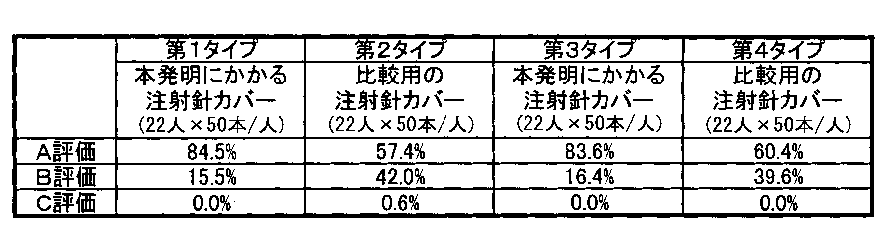
- the evaluation of the smoothness of operation was made in three stages. When it operated very smoothly, it was set as A evaluation. Although there was a feeling of being caught, when it moved to the last, it was set as B evaluation. C evaluation was given when there was strong catch and operation stopped on the way.
- the evaluation results are shown in Table 1.
- the ratio of A evaluation to C evaluation for each subject is shown in FIG. In FIG. 13, the ratio of evaluation is shown for each type of sample.
- Each band graph shown in FIG. 13 shows the rate of evaluation for each subject.
- the A evaluation in the first type sample was 84.5%.
- the B rating of the first type sample was 15.5%.
- the C rating of the first type sample was 0.0%.
- the A rating of the second type sample was 57.4%.
- the B rating of the second type sample was 42.0%.
- the C rating for the second type sample was 0.6%.
- the A rating of the third type sample was 83.6%.
- the B rating for the third type sample was 16.4%.
- the C rating for the third type sample was 0%.
- the A rating of the fourth type sample was 60.4%.
- the B rating of the fourth type sample was 39.6%.
- the C rating of the fourth type sample was 0%.
- the ratio of A evaluation in the first type sample is about 30% higher than the ratio of A evaluation in the second type sample.
- the ratio of A evaluation in the third type sample is about 20% higher than the ratio of A evaluation in the fourth type sample. Accordingly, it can be seen that the needle cover according to the present invention is much less likely to feel that it is caught than the comparative needle cover.
- the configuration of the connecting portion 102 is not limited to the above-described one.
- the connecting portion 102 may be a kind of a flexible body portion that is not plate-like, like the plate-like portion. Similar to the plate-like portion, the flexible body portion is formed in a direction orthogonal to the direction from the distal end side axial space 84 toward the base side axial space 80 when the force receiving portion 100 receives a force from the injection needle 24. Also, it is greatly bent in the direction from the distal end side axial space 84 toward the base side axial space 80.
- the flexible body portion bends, and there is a possibility that the injection needle contact portion 66 starts to slide on the side surface of the injection needle 24 as compared with the case where this does not occur. Get higher.
- the possibility that the injection needle contact portion 66 starts to slide on the side surface of the injection needle 24 becomes higher, the possibility that the injection needle cover 30 extends smoothly becomes higher than the case where the injection needle contact portion 66 does not slide.
- the specific structure of such a flexible body part is not particularly limited.
- FIG. 14 shows an example of such a flexible body part 200.
- the flexible body portion 200 may have a low deformation portion 210 and a high deformation portion 212.
- the low deformation portion 210 extends in a direction intersecting the base side wall portion 60.
- the high deformation portion 212 extends along the low deformation portion 210 and is more easily deformed than the low deformation portion 210.
- the high deformation portion 212 may be provided with a slit 220. Moreover, the slit 220 extends along the low deformation portion 210. In this case, if the low deformation portion 210 and the high deformation portion 212 extend in a direction intersecting the base side wall portion 60, the flexibility of the bending body portion 200 is uniform in any portion of the bending body portion 200.
- the flexible body portion is different from that shown in FIG. 14 in the direction in which the slit extends (and thus the direction in which the low deformation portion 210 and the high deformation portion 212 extend). It may be one with a round hole.
- the connecting portion 102 may be a kind of structural body portion similar to the flexible body portion, and may be different from the flexible body portion, instead of the flexible body portion. This structural body portion projects from the end portion of the bottom plate portion 130 facing the in-cylinder space 82 (the end portion where the bottom curved surface 140 is provided) toward the base-side axial space 80.
- the specific structure of this structure part is not specifically limited.
- the form of the easy sliding portion 112 is not limited to the above-described one.
- the easy sliding portion 112 may be porous so as to contain a lubricant.
- the easy sliding portion 112 may have a flat surface that contacts the injection needle 24.
- the position of the injection needle contact portion 66 is not limited to the above-described location.
- the injection needle contact portion 66 may be disposed in the in-cylinder space 82.
- the connecting portion 102 may connect the cylindrical portion 62 and the force receiving portion 100.
- the form of the injection needle contact portion 66 is not particularly limited.
- the needle contact portion 66 may have a different thickness for each portion.
- this paragraph refers to an invention different from the present invention.
- the connecting portion only needs to have a flexible body portion, and the force receiving portion does not have to have an easy sliding portion.
- the possibility that the injection needle cover 30 can be smoothly extended can be increased because the connecting portion has the flexible body portion.
- the invention described in this paragraph is otherwise the same as the invention described in the present invention, that is, the paragraph before this paragraph.
- Tip side axial space 90 Fixing claw 100 ... Force receiving portion 102 ... Connecting portion 110 ... Injection needle facing portion 112 ... Easy sliding part 114 ... Edge 120 ... Injection needle contact section 122 ... Injection needle position correction section 130 ... Bottom plate part 132 ... Plate-like part 140 ... Bottom curved surface 150 ... Columnar part 152 ... Detachment part 154 ... Inclined surface 160 Gap 170 ... thumb 180 ... bottom edge 190 ... needle contacting portion 210 ... low deformation portion 212 ... highly deformable portions 220 ... slit
Landscapes
- Health & Medical Sciences (AREA)
- Engineering & Computer Science (AREA)
- Hematology (AREA)
- Anesthesiology (AREA)
- Biomedical Technology (AREA)
- Heart & Thoracic Surgery (AREA)
- Vascular Medicine (AREA)
- Life Sciences & Earth Sciences (AREA)
- Animal Behavior & Ethology (AREA)
- General Health & Medical Sciences (AREA)
- Public Health (AREA)
- Veterinary Medicine (AREA)
- Environmental & Geological Engineering (AREA)
- Infusion, Injection, And Reservoir Apparatuses (AREA)
Abstract
Description
[発明の背景]
シリンダと前記シリンダから突出する注射針とを備えるシリンジのうち前記注射針が前記シリンダから突出する面である注射針突出面に前記注射針を取り囲むように固定されるベース部と、
前記ベース部に設けられるヒンジであるベースヒンジと、
前記注射針の中心軸と直交する軸であるベース軸を中心に回るよう前記ベースヒンジを介して前記ベース部に接続され、前記シリンダに対する前記注射針の接続個所が嵌まるための空間を形成する接続箇所嵌入空間形成部と、
前記接続箇所嵌入空間形成部に設けられるヒンジである連結ヒンジと、
前記ベース軸に平行な軸である連結軸を中心に回るよう前記連結ヒンジを介して前記接続箇所嵌入空間形成部に接続される注射針包囲部とを備え、
前記注射針包囲部が、
前記注射針の一部が嵌まるためのベース側軸状空間を形成するベース側壁部の対と、
前記ベース側壁部の対に連なり、前記ベース側軸状空間と連通する筒内空間を形成する筒部と、
前記筒部に連なり、前記注射針の先端部が嵌まるための先端側軸状空間を前記筒内空間と連通するよう形成し、前記ベース側軸状空間と前記先端側軸状空間とが一列に並ぶよう前記筒部から見て前記ベース側壁部の対とは反対側に配置される先端側壁部の対と、
前記ベース側軸状空間と前記筒内空間とのうちいずれかであって前記ベースヒンジが開くと前記注射針に接触する位置に配置される注射針接触部とを有している注射針カバーであって、
前記注射針接触部が、
前記注射針に接触すると前記注射針から力を受ける受力部と、
前記ベース側壁部の対および前記筒部のいずれかと前記受力部とを連結する連結部とを有しており、
前記受力部が、前記ベース側軸状空間と前記先端側軸状空間とに前記注射針が嵌まった後に前記注射針に対向する部分よりも前記先端側軸状空間側の領域である注射針隣接領域に配置される、前記連結部の表面と静摩擦係数が等しく前記注射針と交差するエッジが前記注射針に沿って滑る場合に比べて前記注射針に沿って容易に滑る容易滑走部を有することを特徴とする。
前記容易滑走部が、前記連結ヒンジが開く際の前記容易滑走部の移動方向に沿って延びる注射針接触区間を有することを特徴とする。
前記注射針接触区間に、前記連結ヒンジが開く際の前記容易滑走部の移動方向における前記注射針接触区間の一端から他端にわたる曲面が設けられていることを特徴とする。
前記接続箇所嵌入空間形成部が前記ベース軸を回転中心とするモーメントを受けるためのモーメント受け部44を有することを特徴とする。
前記連結部が、
前記ベース側軸状空間のうち前記筒内空間との境界に配置され、前記ベース側壁部に両端が接続される底板部と、
前記底板部のうち前記筒内空間に対向する端部から前記ベース側軸状空間に向かって突出する構造体部とを有しており、
前記底板部のうち前記ベース側軸状空間に対向する面とは反対側の面から前記端部にわたる箇所に曲面が設けられていることを特徴とする。
前記連結部が、前記受力部が前記注射針から前記力を受けると、前記先端側軸状空間から前記ベース側軸状空間へ向かう方向に対して直交する方向よりも前記先端側軸状空間から前記ベース側軸状空間へ向かう方向へ大きく撓む、撓み体部を有していることを特徴とする。
前記撓み体部が、前記先端側軸状空間から前記ベース側軸状空間へ向かう方向である撓み方向に対して直交するよう配置される板状部を有することを特徴とする。
前記板状部が、前記ベース側壁部の対のいずれかと隙間を空けて対向し、
前記受力部が、前記ベース側壁部の対のうち前記板状部が前記隙間を空けて対向しているものと隙間を空けて対向していることを特徴とする。
前記注射針包囲部が、前記ベース側軸状空間内に突出し、前記ベース側軸状空間と前記先端側軸状空間とに前記注射針が嵌まる際に前記注射針に引掛かる引掛部をさらに有しており、
前記引掛部が、
前記ベース側軸状空間内に前記ベース側壁部の対に沿うよう配置される柱状部と、
前記柱状部から前記ベース側壁部の対の一方に向かって突出する外れ止め部と、
前記柱状部の先端部から前記外れ止め部の先端部にわたって配置されており、前記ベース側壁部の対に沿う方向に対して傾斜する傾斜面とを有しており、
前記板状部が、前記外れ止め部が突出する方の前記ベース側壁部に接続され、かつ、前記外れ止め部が突出する方とは異なる方の前記ベース側壁部と前記隙間を空けて対向することを特徴とする。
前記撓み体部が、
前記ベース側壁部に対して交差する方向に延びる低変形部と、
前記低変形部に沿って延び、かつ、前記低変形部より変形しやすい高変形部とを有することを特徴とする。
前記高変形部に、前記低変形部に沿って延びるスリットが設けられていることを特徴とする。
図1は、本実施形態にかかる注射針カバー30がシリンジ20に取り付けられている状況を示す図である。図1に示されるように、本実施形態にかかる注射針カバー30は、周知のシリンジ20に取り付けられる。シリンジ20の使用前、注射針24は円筒状カバー26によって覆われている。本実施形態にかかる注射針カバー30は、そのシリンジ20が使用された後、そのシリンジ20の注射針24を包囲する。図2は、本実施形態にかかる注射針カバー30が注射針24を包囲している状況を示す図である。円筒状カバー26はシリンジ20の使用時に取り除かれる。なお、本実施形態においては、周知の注射針24が取り付けられる周知の筒をシリンダ22と称する。本実施形態においては、注射針24とそれが取り付けられるシリンダ22とをシリンジ20と総称する。
図3は、本発明の実施形態にかかる注射針カバー30の外観図である。図3(A)は本実施形態にかかる注射針カバー30の平面図である。図3(B)は本実施形態にかかる注射針カバー30の正面図である。図3(C)は本実施形態にかかる注射針カバー30の底面図である。本実施形態にかかる注射針カバー30は図3に基づいて説明される。本実施形態にかかる注射針カバー30は合成樹脂製である。本実施形態にかかる注射針カバー30は、ベース部32と、ベースヒンジ34の対と、接続箇所嵌入空間形成部36と、連結ヒンジ38の対と、注射針包囲部40とを備える。本実施形態の場合、これらは一体となっている。
図9は、本実施形態にかかる注射針カバー30の動作直前の状況を示す図である。図10は、本実施形態にかかる注射針カバー30の動作中の状況を示す図である。この図において、注射針カバー30の一部は切り欠かれている。図11は、本実施形態にかかる注射針カバー30の動作中であって連結ヒンジ38の開きが悪い場合を示す図である。この図においても、注射針カバー30の一部は切り欠かれている。本実施形態にかかる注射針カバー30の動作は、図9ないし図11に基づいて説明される。
本実施形態の場合、注射針カバー30は折り畳まれた状態で予めシリンジ20に取り付けられる。ベース部32によって注射針カバー30はシリンジ20のうち注射針24が突出する面に固定される。その際、注射針24は筒内空間82を貫通している。注射針カバー30は注射針24の側面に沿って注射針接触部66を滑らせることで伸長する。注射針24の側面に沿って注射針接触部66が滑ることに伴い、接続箇所嵌入空間形成部36が形成する空間に、シリンダ22に対する注射針24の接続個所が収容される。また、筒内空間82を貫通していた注射針24は、次第に、ベース側軸状空間80および先端側軸状空間84に嵌まる。注射針24は、ベース側軸状空間80および先端側軸状空間84に嵌まる際、筒内空間82を貫通している。ベース側軸状空間80が筒内空間82と連通し、筒内空間82が先端側軸状空間84と連通し、ベース側軸状空間80と先端側軸状空間84とが一列に並び、かつ、筒部62から見てベース側壁部60の対とは反対側に先端側壁部64の対が配置されるためである。注射針24の側面を注射針接触部66が滑り始めるに先立って、ベースヒンジ34が開く。ベースヒンジ34が開くと、接続箇所嵌入空間形成部36は回る。接続箇所嵌入空間形成部36が回ると注射針包囲部40も回る。連結ヒンジ38を介して接続箇所嵌入空間形成部36に接続されているためである。注射針包囲部40が回ると、注射針24の側面に注射針接触部66が接触する。連結ヒンジ38の開きが悪い場合を除けば、受力部100のうちベース側軸状空間80と先端側軸状空間84とに注射針24が嵌まった後に注射針24に対向する部分(すなわち注射針対向部110)およびそこから見て先端側軸状空間84側の領域が注射針24の側面に直接接触することが多い。連結ヒンジ38の開きが悪い場合は、注射針対向部110および容易滑走部112よりも、むしろ、図11に示されているように、底曲面140の方が、注射針24の側面を注射針接触部66が滑り始める際には注射針24の側面に直接接触しやすい。いずれにせよ、注射針24の側面を注射針接触部66が滑り始める際には、連結ヒンジ38よりもベースヒンジ34の方がよく開く。ベースヒンジ34が開くことで、注射針包囲部40が回る。これにより、注射針24の側面に注射針接触部66が接触するためである。受力部100が容易滑走部112を有しており、かつ、容易滑走部112が注射針隣接領域に配置されるので、注射針24の側面を注射針接触部66が滑り始めた際に、受力部100は、連結部102の表面と静摩擦係数が等しく注射針24と交差するエッジ114が注射針24に沿って滑る場合に比べ、容易に滑る。受力部100が容易に滑るので、注射針カバー30はスムーズに伸長しやすくなる。
図1ないし図11において説明された注射針カバー30(以下「本発明にかかる注射針カバー」と称する)と次に述べられる比較用の注射針カバーとを使用して動作を比較した。比較用注射針カバーは、次に述べられる点を除けば、本発明にかかる注射針カバーと同一構造である。その点とは、本発明にかかる注射針カバーの容易滑走部112に代えてエッジ114を有しており、かつ、底曲面140に代えて底エッジ180を有している点である。図12に、比較用注射カバーにおける注射針接触部190の断面図が示される。
今回開示された実施形態はすべての点で例示である。本発明の範囲は上述した実施形態に基づいて制限されるものではなく、本発明の趣旨を逸脱しない範囲で種々の設計変更をしてもよいのはもちろんである。
22…シリンダ
24…注射針
26…円筒状カバー
28…注射針突出面
30…注射針カバー
32…ベース部
34…ベースヒンジ
36…接続箇所嵌入空間形成部
38…連結ヒンジ
40…注射針包囲部
42…保持部
44…モーメント受け部
46…アーム部
48…リブ
50…中心軸
52…ベース軸
54…連結軸
60…ベース側壁部
62…筒部
64…先端側壁部
66…注射針接触部
68…引掛部
70…針先端固定部
80…ベース側軸状空間
82…筒内空間
84…先端側軸状空間
90…固定爪
100…受力部
102…連結部
110…注射針対向部
112…容易滑走部
114…エッジ
120…注射針接触区間
122…注射針位置矯正区間
130…底板部
132…板状部
140…底曲面
150…柱状部
152…外れ止め部
154…傾斜面
160…隙間
170…親指
180…底エッジ
190…注射針接触部
210…低変形部
212…高変形部
220…スリット
Claims (11)
- シリンダと前記シリンダから突出する注射針とを備えるシリンジのうち前記注射針が前記シリンダから突出する面である注射針突出面に前記注射針を取り囲むように固定されるベース部と、
前記ベース部に設けられるヒンジであるベースヒンジと、
前記注射針の中心軸と直交する軸であるベース軸を中心に回るよう前記ベースヒンジを介して前記ベース部に接続され、前記シリンダに対する前記注射針の接続個所が嵌まるための空間を形成する接続箇所嵌入空間形成部と、
前記接続箇所嵌入空間形成部に設けられるヒンジである連結ヒンジと、
前記ベース軸に平行な軸である連結軸を中心に回るよう前記連結ヒンジを介して前記接続箇所嵌入空間形成部に接続される注射針包囲部とを備え、
前記注射針包囲部が、
前記注射針の一部が嵌まるためのベース側軸状空間を形成するベース側壁部の対と、
前記ベース側壁部の対に連なり、前記ベース側軸状空間と連通する筒内空間を形成する筒部と、
前記筒部に連なり、前記注射針の先端部が嵌まるための先端側軸状空間を前記筒内空間と連通するよう形成し、前記ベース側軸状空間と前記先端側軸状空間とが一列に並ぶよう前記筒部から見て前記ベース側壁部の対とは反対側に配置される先端側壁部の対と、
前記ベース側軸状空間と前記筒内空間とのうちいずれかであって前記ベースヒンジが開くと前記注射針に接触する位置に配置される注射針接触部とを有している注射針カバーであって、
前記注射針接触部が、
前記注射針に接触すると前記注射針から力を受ける受力部と、
前記ベース側壁部の対および前記筒部のいずれかと前記受力部とを連結する連結部とを有しており、
前記受力部が、前記ベース側軸状空間と前記先端側軸状空間とに前記注射針が嵌まった後に前記注射針に対向する部分よりも前記先端側軸状空間側の領域である注射針隣接領域に配置される、前記連結部の表面と静摩擦係数が等しく前記注射針と交差するエッジが前記注射針に沿って滑る場合に比べて前記注射針に沿って容易に滑る容易滑走部を有することを特徴とする注射針カバー。 - 前記容易滑走部が、前記連結ヒンジが開く際の前記容易滑走部の移動方向に沿って延びる注射針接触区間を有することを特徴とする請求項1に記載の注射針カバー。
- 前記注射針接触区間に、前記連結ヒンジが開く際の前記容易滑走部の移動方向における前記注射針接触区間の一端から他端にわたる曲面が設けられていることを特徴とする請求項2に記載の注射針カバー。
- 前記接続箇所嵌入空間形成部が前記ベース軸を回転中心とするモーメントを受けるためのモーメント受け部を有することを特徴とする請求項1ないし請求項3のいずれかに記載の注射針カバー。
- 前記連結部が、
前記ベース側軸状空間のうち前記筒内空間との境界に配置され、前記ベース側壁部に両端が接続される底板部と、
前記底板部のうち前記筒内空間に対向する端部から前記ベース側軸状空間に向かって突出する構造体部とを有しており、
前記底板部のうち前記ベース側軸状空間に対向する面とは反対側の面から前記端部にわたる箇所に曲面が設けられていることを特徴とする請求項1ないし請求項4のいずれかに記載の注射針カバー。 - 前記連結部が、前記受力部が前記注射針から前記力を受けると、前記先端側軸状空間から前記ベース側軸状空間へ向かう方向に対して直交する方向よりも前記先端側軸状空間から前記ベース側軸状空間へ向かう方向へ大きく撓む、撓み体部を有していることを特徴とする請求項1ないし請求項5のいずれかに記載の注射針カバー。
- 前記撓み体部が、前記先端側軸状空間から前記ベース側軸状空間へ向かう方向である撓み方向に対して直交するよう配置される板状部を有することを特徴とする請求項6に記載の注射針カバー。
- 前記板状部が、前記ベース側壁部の対のいずれかと隙間を空けて対向し、
前記受力部が、前記ベース側壁部の対のうち前記板状部が前記隙間を空けて対向しているものと隙間を空けて対向していることを特徴とする請求項7に記載の注射針カバー。 - 前記注射針包囲部が、前記ベース側軸状空間内に突出し、前記ベース側軸状空間と前記先端側軸状空間とに前記注射針が嵌まる際に前記注射針に引掛かる引掛部をさらに有しており、
前記引掛部が、
前記ベース側軸状空間内に前記ベース側壁部の対に沿うよう配置される柱状部と、
前記柱状部から前記ベース側壁部の対の一方に向かって突出する外れ止め部と、
前記柱状部の先端部から前記外れ止め部の先端部にわたって配置されており、前記ベース側壁部の対に沿う方向に対して傾斜する傾斜面とを有しており、
前記板状部が、前記外れ止め部が突出する方の前記ベース側壁部に接続され、かつ、前記外れ止め部が突出する方とは異なる方の前記ベース側壁部と前記隙間を空けて対向することを特徴とする請求項8に記載の注射針カバー。 - 前記撓み体部が、
前記ベース側壁部に対して交差する方向に延びる低変形部と、
前記低変形部に沿って延び、かつ、前記低変形部より変形しやすい高変形部とを有することを特徴とする請求項6ないし請求項9のいずれかに記載の注射針カバー。 - 前記高変形部に、前記低変形部に沿って延びるスリットが設けられていることを特徴とする請求項10に記載の注射針カバー。
Priority Applications (5)
| Application Number | Priority Date | Filing Date | Title |
|---|---|---|---|
| JP2016564906A JP6588466B2 (ja) | 2014-12-19 | 2015-12-17 | 注射針カバー |
| US15/535,186 US10357618B2 (en) | 2014-12-19 | 2015-12-17 | Injection-needle cover |
| EP15870063.3A EP3235532B8 (en) | 2014-12-19 | 2015-12-17 | Injection-needle cover |
| ES15870063T ES2748704T3 (es) | 2014-12-19 | 2015-12-17 | Cubierta de aguja de inyección |
| CN201580063511.0A CN106999676B (zh) | 2014-12-19 | 2015-12-17 | 注射针套 |
Applications Claiming Priority (2)
| Application Number | Priority Date | Filing Date | Title |
|---|---|---|---|
| JP2014257759 | 2014-12-19 | ||
| JP2014-257759 | 2014-12-19 |
Publications (1)
| Publication Number | Publication Date |
|---|---|
| WO2016098861A1 true WO2016098861A1 (ja) | 2016-06-23 |
Family
ID=56126744
Family Applications (1)
| Application Number | Title | Priority Date | Filing Date |
|---|---|---|---|
| PCT/JP2015/085393 WO2016098861A1 (ja) | 2014-12-19 | 2015-12-17 | 注射針カバー |
Country Status (6)
| Country | Link |
|---|---|
| US (1) | US10357618B2 (ja) |
| EP (1) | EP3235532B8 (ja) |
| JP (1) | JP6588466B2 (ja) |
| CN (1) | CN106999676B (ja) |
| ES (1) | ES2748704T3 (ja) |
| WO (1) | WO2016098861A1 (ja) |
Cited By (1)
| Publication number | Priority date | Publication date | Assignee | Title |
|---|---|---|---|---|
| WO2018186119A1 (ja) | 2017-04-05 | 2018-10-11 | 武田薬品工業株式会社 | シリンジ |
Citations (7)
| Publication number | Priority date | Publication date | Assignee | Title |
|---|---|---|---|---|
| JPH04244167A (ja) * | 1990-08-01 | 1992-09-01 | Smiths Ind Medical Syst Inc | 針に使用する安全装置 |
| JPH07250898A (ja) * | 1993-11-24 | 1995-10-03 | Becton Dickinson & Co | 片手操作可能なシールド可能な針組立体 |
| JP2003514596A (ja) * | 1999-11-04 | 2003-04-22 | タイコ・ヘルスケア・グループ・リミテッド・パートナーシップ | 再アクセス可能な医療針安全装置および方法 |
| JP2005521537A (ja) * | 2002-04-05 | 2005-07-21 | スペシャライズド・ヘルス・プロダクツ・インコーポレーテッド | 医療用針の安全シールド |
| JP2005528188A (ja) * | 2002-06-06 | 2005-09-22 | タイコ・ヘルスケア・グループ・リミテッド・パートナーシップ | 医療用針のための安全シールド |
| JP2009535105A (ja) * | 2006-04-26 | 2009-10-01 | タイコ ヘルスケア グループ リミテッド パートナーシップ | 医療用針装置と併用するための安全シールド装置および取り付け構造 |
| JP2010531675A (ja) * | 2008-05-13 | 2010-09-30 | ローレンス アール.コー アンド ニーナ メレル−コー,トラスティーズ,オア ゼア サクセサーズ,アンダー ザ ローレンス アール.コー アンド ニーナ メレル−コー ファミリー トラスト デイティド | 注射針保護アッセンブリ及びその使用方法 |
Family Cites Families (3)
| Publication number | Priority date | Publication date | Assignee | Title |
|---|---|---|---|---|
| US5823997A (en) * | 1995-01-10 | 1998-10-20 | Specialized Health Products, Inc. | Medical needle safety apparatus and methods |
| US7198618B2 (en) | 1999-11-04 | 2007-04-03 | Tyco Healthcare Group Lp | Safety shield for medical needles |
| US7361159B2 (en) | 2001-03-02 | 2008-04-22 | Covidien Ag | Passive safety shield |
-
2015
- 2015-12-17 WO PCT/JP2015/085393 patent/WO2016098861A1/ja active Application Filing
- 2015-12-17 US US15/535,186 patent/US10357618B2/en active Active
- 2015-12-17 JP JP2016564906A patent/JP6588466B2/ja active Active
- 2015-12-17 ES ES15870063T patent/ES2748704T3/es active Active
- 2015-12-17 CN CN201580063511.0A patent/CN106999676B/zh active Active
- 2015-12-17 EP EP15870063.3A patent/EP3235532B8/en active Active
Patent Citations (7)
| Publication number | Priority date | Publication date | Assignee | Title |
|---|---|---|---|---|
| JPH04244167A (ja) * | 1990-08-01 | 1992-09-01 | Smiths Ind Medical Syst Inc | 針に使用する安全装置 |
| JPH07250898A (ja) * | 1993-11-24 | 1995-10-03 | Becton Dickinson & Co | 片手操作可能なシールド可能な針組立体 |
| JP2003514596A (ja) * | 1999-11-04 | 2003-04-22 | タイコ・ヘルスケア・グループ・リミテッド・パートナーシップ | 再アクセス可能な医療針安全装置および方法 |
| JP2005521537A (ja) * | 2002-04-05 | 2005-07-21 | スペシャライズド・ヘルス・プロダクツ・インコーポレーテッド | 医療用針の安全シールド |
| JP2005528188A (ja) * | 2002-06-06 | 2005-09-22 | タイコ・ヘルスケア・グループ・リミテッド・パートナーシップ | 医療用針のための安全シールド |
| JP2009535105A (ja) * | 2006-04-26 | 2009-10-01 | タイコ ヘルスケア グループ リミテッド パートナーシップ | 医療用針装置と併用するための安全シールド装置および取り付け構造 |
| JP2010531675A (ja) * | 2008-05-13 | 2010-09-30 | ローレンス アール.コー アンド ニーナ メレル−コー,トラスティーズ,オア ゼア サクセサーズ,アンダー ザ ローレンス アール.コー アンド ニーナ メレル−コー ファミリー トラスト デイティド | 注射針保護アッセンブリ及びその使用方法 |
Non-Patent Citations (1)
| Title |
|---|
| See also references of EP3235532A4 * |
Cited By (6)
| Publication number | Priority date | Publication date | Assignee | Title |
|---|---|---|---|---|
| WO2018186119A1 (ja) | 2017-04-05 | 2018-10-11 | 武田薬品工業株式会社 | シリンジ |
| CN110505893A (zh) * | 2017-04-05 | 2019-11-26 | 武田药品工业株式会社 | 注射器 |
| JPWO2018186119A1 (ja) * | 2017-04-05 | 2020-02-13 | 武田薬品工業株式会社 | シリンジ |
| EP3607983A4 (en) * | 2017-04-05 | 2020-10-14 | Takeda Pharmaceutical Company Limited | SYRINGE |
| JP7026918B2 (ja) | 2017-04-05 | 2022-03-01 | 武田薬品工業株式会社 | シリンジ |
| US11318258B2 (en) | 2017-04-05 | 2022-05-03 | Takeda Pharmaceutical Company Limited | Syringe |
Also Published As
| Publication number | Publication date |
|---|---|
| JPWO2016098861A1 (ja) | 2017-11-02 |
| JP6588466B2 (ja) | 2019-10-09 |
| CN106999676A (zh) | 2017-08-01 |
| EP3235532B1 (en) | 2019-07-31 |
| EP3235532A1 (en) | 2017-10-25 |
| EP3235532A4 (en) | 2018-07-18 |
| CN106999676B (zh) | 2020-01-31 |
| ES2748704T3 (es) | 2020-03-17 |
| US10357618B2 (en) | 2019-07-23 |
| US20170326307A1 (en) | 2017-11-16 |
| EP3235532B8 (en) | 2019-09-18 |
Similar Documents
| Publication | Publication Date | Title |
|---|---|---|
| US20020065488A1 (en) | Needlepoint-covering member, method of assembling an injection needle with a needlepoint-covering member, and injection syringe with a needlepoint-covering member | |
| JP5365680B2 (ja) | 安全針組立体 | |
| US8870835B2 (en) | Needle safety device for medical devices | |
| JP4377222B2 (ja) | ヒンジのある針シールドと可撓性のカニューレロックを有する針シールド組立て品 | |
| JP2017099884A (ja) | 双安定構造を備える針デバイスおよび関連方法 | |
| JP2007521918A (ja) | ニードル先端保護装置 | |
| JP2008514346A (ja) | 保護用クリップ | |
| AU2009227517A1 (en) | Needle safety device | |
| US7566325B2 (en) | Winged medical needle device | |
| RU2729549C1 (ru) | Безопасная инъекционная игла | |
| JP6588466B2 (ja) | 注射針カバー | |
| CN110996865B (zh) | 套管用保持器 | |
| JP7413643B2 (ja) | 医療用針 | |
| JP2004523311A (ja) | 安全性が改善された医療用途のための装置、特に注射器 | |
| JP2004113523A (ja) | プロテクタ | |
| WO2017094708A1 (ja) | 刺通針付きカニューレ | |
| JP7419809B2 (ja) | 穿刺器具 | |
| EP3415092A1 (en) | Injector | |
| JP2019107241A (ja) | プロテクタ及び医療用針組立体 | |
| EP4197573A1 (en) | Winged needle assembly, packaging material for winged needle assembly, cap for winged needle assembly, and winged needle assembly set | |
| WO2014033903A1 (ja) | 翼状針 | |
| JP6867101B2 (ja) | 留置針 | |
| US11850409B2 (en) | Medical needle | |
| WO2024010046A1 (ja) | 翼状針用の針先プロテクタ | |
| WO2022103325A1 (en) | Lancet assembly |
Legal Events
| Date | Code | Title | Description |
|---|---|---|---|
| 121 | Ep: the epo has been informed by wipo that ep was designated in this application |
Ref document number: 15870063 Country of ref document: EP Kind code of ref document: A1 |
|
| ENP | Entry into the national phase |
Ref document number: 2016564906 Country of ref document: JP Kind code of ref document: A |
|
| REEP | Request for entry into the european phase |
Ref document number: 2015870063 Country of ref document: EP |
|
| WWE | Wipo information: entry into national phase |
Ref document number: 15535186 Country of ref document: US |
|
| NENP | Non-entry into the national phase |
Ref country code: DE |