WO2016098427A1 - 媒体鑑別装置及び媒体取引装置 - Google Patents
媒体鑑別装置及び媒体取引装置 Download PDFInfo
- Publication number
- WO2016098427A1 WO2016098427A1 PCT/JP2015/078544 JP2015078544W WO2016098427A1 WO 2016098427 A1 WO2016098427 A1 WO 2016098427A1 JP 2015078544 W JP2015078544 W JP 2015078544W WO 2016098427 A1 WO2016098427 A1 WO 2016098427A1
- Authority
- WO
- WIPO (PCT)
- Prior art keywords
- medium
- detection unit
- roller
- unit
- feature detection
- Prior art date
- Legal status (The legal status is an assumption and is not a legal conclusion. Google has not performed a legal analysis and makes no representation as to the accuracy of the status listed.)
- Ceased
Links
Images


Classifications
-
- G—PHYSICS
- G07—CHECKING-DEVICES
- G07D—HANDLING OF COINS OR VALUABLE PAPERS, e.g. TESTING, SORTING BY DENOMINATIONS, COUNTING, DISPENSING, CHANGING OR DEPOSITING
- G07D7/00—Testing specially adapted to determine the identity or genuineness of valuable papers or for segregating those which are unacceptable, e.g. banknotes that are alien to a currency
- G07D7/04—Testing magnetic properties of the materials thereof, e.g. by detection of magnetic imprint
Definitions
- the present invention relates to a medium discrimination device and a medium transaction device, and is suitable for application to, for example, an automatic teller machine (ATM) or the like that performs a desired transaction by inserting a medium such as banknotes.
- ATM automatic teller machine
- an automatic cash transaction apparatus or the like used in a financial institution or the like, for example, the customer deposits cash such as banknotes or coins according to the transaction contents with the customer, and also withdraws cash to the customer.
- a banknote deposit / withdrawal port for transferring banknotes to / from customers, a discrimination unit for discriminating the denomination and authenticity of inserted banknotes, and temporarily holding inserted banknotes. The thing which has a temporary storage part to perform and the banknote storage which stores a banknote for every denomination is proposed.
- This automatic teller machine in a deposit transaction, when a customer inserts a banknote into a banknote deposit / withdrawal port, the inserted banknote is discriminated by a discrimination unit, and a banknote discriminated from a normal banknote is held in a temporary holding unit, The banknotes identified as not to be traded are returned to the banknote deposit / withdrawal port and returned to the customer. Subsequently, when the deposit amount is confirmed by the customer, the automatic teller machine re-differentiates the denomination of the banknote held in the temporary holding unit by the discrimination unit, and stores it in the banknote storage according to the identified denomination. .
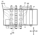
- the conventional discrimination unit 213 includes a first transport unit 225, a magnetic detection unit 226, a second transport unit 227, an optical detection unit 28, and a thickness detection so as to go from the rear side to the front side.
- Each module such as the unit 229 is sequentially arranged.
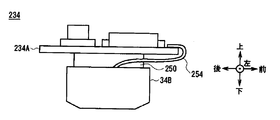
- the magnetic detection unit 226 is provided with a magnetic sensor 234 having a magnetic detection element 34B for detecting the magnetism of a bill and a magnetic sensor substrate 234A for controlling the magnetic detection element 34B.
- the magnetic sensor substrate 234A has a flat plate shape, and is fixed to the magnetic detection element 34B via a bracket 250 shown in FIG. 18 in a state where the plate surface is along the front-rear direction, which is the direction in which bills are conveyed.
- the first transport unit 225 includes a transport roller 231 composed of a plurality of rubber rollers 231B disposed below the transport path 24 through which bills are transported, and a tension roller 233 disposed above the transport path 24.
- the banknotes are transported by sandwiching and rotating the banknotes between the transport roller 231 and the tension roller 233.
- the second transport unit 227 includes a transport roller 237 including a plurality of rubber rollers 237B disposed below the transport path 24, and a tension roller 239 disposed above the transport path 24.
- a banknote is conveyed by pinching and rotating a banknote with the conveyance roller 237 and the tension roller 239.
- the plurality of rubber rollers 236B constituting the guide roller 236 in the magnetic detection unit 226, the conveyance roller 231 and the tension roller of the first conveyance unit 225 adjacent to the rear side of the magnetic detection unit 226 are included.
- the vibration of the roller when the banknote contacts the various rollers is suppressed, It is desired to improve detection accuracy in the magnetic detection unit 226.
- the discrimination unit 213 has the first conveyance unit 225 and the second conveyance due to restrictions on the internal space and restrictions on the intervals between the conveyance roller 231 and the tension roller 233 and the conveyance roller 237 and the tension roller 239 when the banknote is conveyed. It is difficult to increase the distance from the portion 227.
- the discrimination unit 213 makes it difficult to dispose the magnetic sensor substrate 234A between the tension roller 233 and the tension roller 239. There is a possibility of becoming.
- the present invention has been made in view of the above points, and intends to propose a medium discrimination device and a medium transaction device that can improve the accuracy of detection of magnetism from a medium.
- the feature detection unit that detects the feature of the medium to be transported, and the feature detection unit are arranged along the transport direction of the medium, A plurality of conveyance rollers that convey the medium, a plurality of opposed rollers that are arranged to face the conveyance roller across the conveyance path that conveys the medium, and that convey the medium while sandwiching the medium between the conveyance rollers, and a plurality of opposed A feature detection unit substrate that is positioned between the rollers and is fixed in a state in which the direction along the surface direction intersects the conveyance direction of the medium and that controls the feature detection unit is provided.
- a feature detection unit that detects a feature of the medium to be transported and a plurality of media that are disposed so as to sandwich the feature detection unit along the medium transport direction. Between the plurality of opposing rollers and the plurality of opposing rollers, which are disposed opposite to the conveying rollers across the conveying path for conveying the medium and sandwich the medium between the conveying rollers.
- a feature detection unit substrate that is fixed in a state perpendicular to the medium conveyance direction and controls the feature detection unit is provided.
- the customer reception unit that receives a transaction relating to the medium
- the feature detection unit that detects the characteristic of the medium to be conveyed
- the feature detection unit sandwiched along the medium conveyance direction.
- a plurality of conveying rollers that convey the medium, and a plurality of opposed rollers that are disposed to face the conveying roller across the conveying path that conveys the medium, and that convey the medium while sandwiching the medium between the conveying rollers.
- a feature detection unit substrate is provided that is positioned between the plurality of opposing rollers and is fixed in a state in which the direction along the surface direction intersects the conveyance direction of the medium, and controls the feature detection unit.
- the features of the medium can be accurately read while the feature detection unit substrate is placed between the opposing rollers.
- the feature of the medium can be read with high accuracy while the feature detection unit substrate is placed between the opposing rollers.
- the present invention can realize a medium discrimination device and a medium transaction device that can improve the detection accuracy of magnetism from a medium.
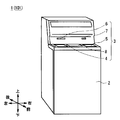
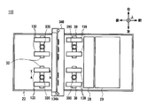
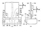
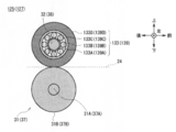
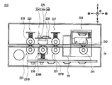
- FIG. 1 It is a perspective view which shows the external appearance structure of an automatic teller machine. It is a left view which shows the internal structure of an automatic teller machine. It is a left view which shows the structure of the discrimination part by 1st Embodiment. It is a top view which shows the structure of the upper unit by 1st Embodiment. It is a top view which shows the structure of the lower unit by 1st Embodiment. It is a front view which shows the structure of a magnetic detection part. The structure of the magnetic sensor by 1st Embodiment is shown, (A) is a rear view, (B) is a left view, (C) is a bottom view. It is a left view which shows the structure of a conveyance roller and a tension roller.
- FIG. 1st Embodiment The structure of the magnetic sensor by 1st Embodiment is shown, (A) is a rear view, (B) is a left view, (C) is a bottom view. It is a left view
- the automatic teller machine 1 is configured with a box-shaped housing 2 as the center, and performs transactions relating to cash with customers.
- the housing 2 is provided with a customer-facing unit 3 at a location where it is easy to insert a bill or operate with a touch panel while the customer faces the front side, that is, a location extending from the top of the front to the top.
- the customer reception unit 3 is provided with a coin deposit / withdrawal port 4, a banknote deposit / withdrawal port 5, a passbook insertion port 6, a card insertion port 7 and a display operation unit 8, and directly exchanges cash, a passbook, etc. with the customer.
- notification of information regarding transactions and operation instructions are accepted.
- the coin deposit / withdrawal port 4 and the banknote deposit / withdrawal port 5 coins and bills to be deposited by customers are respectively input, and coins and bills to be dispensed to customers are respectively discharged.
- the coin deposit / withdrawal port 4 and the banknote deposit / withdrawal port 5 are opened or closed by driving the shutter provided in each.
- the banknote is comprised, for example with the rectangular paper.
- the passbook insertion slot 6 inserts a passbook used in the transaction, and discharges the passbook when the transaction ends.
- a passbook processing section (not shown) for recording transaction contents and the like in a passbook is provided at the back of the passbook insertion slot 6.
- various cards such as a cash card are inserted or ejected.
- a card processing section (not shown) for reading account numbers and the like magnetically recorded on various cards is provided at the back of the card insertion slot 7.
- the display operation unit 8 is integrated with an LCD (Liquid Crystal Display) for displaying an operation screen at the time of transaction, and a touch panel for selecting a transaction type, inputting a personal identification number, transaction amount, and the like.
- LCD Liquid Crystal Display
- the side facing the customer to the automated teller machine 1 is the front side, the opposite is the rear side, the left side and the right side as viewed from the customer facing the front side, the left side and the right side, and the upper side and the lower side. Define and explain.
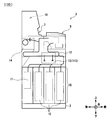
- the customer reception unit 3 the discrimination unit 13 for determining the denomination and authenticity of the banknote, and the received banknote are temporarily held on the upper side.
- a temporary storage unit 14 or the like is provided, and a banknote storage unit 15 or the like that stores banknotes in denominations is provided on the lower side.
- a transport unit 12 that transports banknotes between the units along a transport path indicated by a thick line in the figure.
- the conveyance part 12 is comprised with the motor, gear, pulley, belt, etc. which are not shown in figure, and conveys the short side direction of a banknote as an advancing direction.
- the automatic teller machine 1 is controlled by the control unit 10 as a whole.
- the control unit 10 receives a predetermined operation input via the display operation unit 8 (FIG. 1), and then opens the shutter of the banknote deposit / withdrawal port 5 to accept the banknotes. Let it go.
- the control unit 10 conveys the inserted banknotes to the discrimination unit 13 via the conveyance unit 12 for discrimination, and conveys the banknotes identified as normal banknotes to the temporary storage unit 14 to temporarily hold them.
- the bills identified as not to be traded are conveyed to the bill deposit / withdrawal port 5 and returned to the customer.
- the banknote held in the temporary holding unit 14 is conveyed again to the discrimination unit 13 and the type of money is re-differentiated, It is conveyed to the bill storage unit 15.
- the banknote storage part 15 conveys the banknote discriminated by the discrimination part 13 as undamaged to each banknote storage 16 corresponding to the denomination and stores it so as to be stacked in the thickness direction. Moreover, the banknote storage part 15 conveys the banknote discriminated by the discrimination part 13 when it is damaged to the rejection store
- the automatic teller machine 1 performs the discrimination process of the banknote by the discrimination unit 13 in the deposit process or the withdrawal process of the banknote, determines the transport destination according to the result, and performs the transport by the transport unit 12.
- the bill is conveyed to the front.
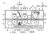
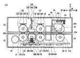
- the discrimination unit 13 forms a conveyance path 24 between the upper unit 22 on the upper side and the lower unit 23 on the lower side, and the banknotes are moved forward or backward along the conveyance path 24. While traveling in the direction, the banknote discrimination process is performed based on the control of the discrimination control unit 20.
- the upper unit 22 is formed with a planar upper transport surface 22A that extends in the front-rear direction above the transport path 24 and faces the paper surface of the banknote.
- the lower unit 23 is opposed to the upper transport surface 22A in the transport path thickness direction, which is the direction along the thickness direction of the banknote, with a predetermined interval, and is extended in the front-rear direction below the transport path 24 to extend the paper surface of the banknote.
- a planar lower conveyance surface 23 ⁇ / b> A is formed opposite to.
- a conveyance path 24 that conveys banknotes along the front-rear direction, which is the conveyance direction, is formed.
- modules such as a first transport unit 25, a magnetic detection unit 26, a second transport unit 27, an optical detection unit 28, and a thickness detection unit 29 are sequentially arranged from the rear side to the front side.
- modules such as a first transport unit 25, a magnetic detection unit 26, a second transport unit 27, an optical detection unit 28, and a thickness detection unit 29 are sequentially arranged from the rear side to the front side.
- the left side plate is omitted and each internal component is schematically shown.
- the modules are arranged close to each other in the front-rear direction due to restrictions on the installation location in the automatic teller machine 1, restrictions for reliably delivering banknotes conveyed along the short side direction, and the like. Has been.
- the first transport unit 25 includes a transport roller 31 disposed below the transport path 24, and a shaft 32, a tension roller 33, a tension spring 33S, and a spring fixing plate 33P disposed above the transport path 24. Has been.
- the transport roller 31 has a configuration in which a plurality of annular rubber rollers 31 ⁇ / b> B are penetrated by a shaft 31 ⁇ / b> A having an elongated cylindrical shape on the left and right.
- the shaft 31A is made of a non-magnetic stainless material, and the driving force of the transport drive motor 60 is fixed to the drive gear fixed to the output shaft of the transport drive motor 60 and the left end portion of the shaft 31A is meshed with the drive gear.
- the drive gear 62 By being transmitted via the drive gear 62 that rotates, it rotates in both directions around the rotation axis along the left and right. For this reason, in the conveyance roller 31, the shaft 31A and the rubber roller 31B rotate together.
- two shafts 32 are arranged side by side on the left and right, are configured in an elongated cylindrical shape on the left and right, are held so as to be swingable in the vertical direction, and are biased downward by the tension spring 33S.
- the shaft 32 does not rotate unlike the shaft 31A.
- the tension roller 33 has a diameter equivalent to that of the transport roller 31 and is formed in an annular shape as a whole, and the shaft 32 passes through the center thereof.
- two tension rollers 33 are provided on the left and right shafts 32 so as to be separated from each other by a predetermined distance in the left-right direction.
- the rubber roller 31 ⁇ / b> B of the transport roller 31 is provided at a location facing the tension roller 33.
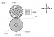
- the tension roller 33 is a combination of an inner ring 33A, a ball 33B, and an outer ring 33C, and is a so-called ball bearing.
- the inner ring 33A, the ball 33B, and the outer ring 33C are each made of a resin that is a nonmagnetic material, or austenitic stainless steel such as SUS304 or SUS316. Further, the inner ring 33 ⁇ / b> A is fixed to the shaft 32. Since the rolling resistance of the ball 33B is extremely small, the tension roller 33 rotates the outer ring 33C smoothly with respect to the shaft 32 and the inner ring 33A, as in a general ball bearing.
- the tension roller 33 has a larger outer diameter than the tension roller 233 (FIGS. 15 and 16) of the conventional discrimination unit 213.
- the bill contact angle ⁇ 1 which is an angle formed by the outer peripheral surface of the rubber roller 31B of the transport roller 31 and the lower transport surface 23A, is set to 30 degrees or less, for example.
- the angle formed by the outer peripheral surface of the outer ring 33C of the tension roller 33 and the upper conveying surface 22A is set to 30 degrees or less, for example.
- the first transport unit 25 presses the tension roller 33 against the transport roller 31, and when there is a bill in the transport path 24 between them, the transport roller 31 while smoothly rotating the outer ring 33 ⁇ / b> C of the tension roller 33. Is transmitted to this bill.
- the 1st conveyance part 25 conveys a banknote forward or back along the conveyance path 24.
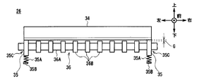
- the magnetic detection unit 26 (FIG. 3) includes a magnetic sensor 34 disposed on the upper side of the conveyance path 24, and a bearing pressing unit 35 and a guide roller 36 disposed on the lower side of the conveyance path 24.
- the magnetic sensor 34 has a substantially rectangular parallelepiped shape that is long in the left-right direction, and is provided with a magnetic detection element 34 ⁇ / b> B as a feature detection element that detects the magnetism of a bill. .
- magnetic detection elements 34B are arranged at a plurality of positions in the left-right direction. The magnetic sensor 34 detects the magnetism of the banknote conveyed through the conveyance path 24 by the magnetic detection element 34 ⁇ / b> B, and sends the detection result to the discrimination control unit 20.
- the magnetic sensor substrate 34A as a magnetic detection unit substrate that controls the magnetic detection element 34B is a flat plate-like glass epoxy substrate, for example, and various electronic components are mounted on the front and rear surfaces, It is fixed to the magnetic detection element 34B via a bracket 50 as a substrate holding member.
- the bracket 50 is substantially N-shaped when viewed from the left side, and is formed by bending a metal plate.
- the bracket 50 includes an element holding portion 51 that is in contact with the rear side surface of the magnetic detection element 34B along the vertical direction from the bottom to the top, and is bent at a right angle forward from the upper end portion of the element holding portion 51 to the front.
- a relay part 52 that contacts the upper side surface of the magnetic detection element 34B along the front-rear direction, and a magnetic sensor that bends rearward and upward from the front end of the relay part 52 along the inclination direction of the magnetic sensor substrate 34A toward the rear upper side.
- the substrate holding portion 53 is in contact with the rear side surface of the substrate 34A.
- the element holding part 51 is formed with an element holding screwing part 51A that extends downward from the rear end of the relay part 52 at both ends in the left-right direction. Thereby, in the element holding part 51, an element holding hollow part 51B without a metal plate is formed between the left element holding screw part 51A and the right element holding screw part 51A. In the element holding portion 51, an element holding screwing portion 51A is screwed to the magnetic detection element 34B by a screw 51C.
- the substrate holding portion 53 is formed with substrate holding screwing portions 53A extending from the front end of the relay portion 52 toward the rear upper side at both ends in the left-right direction. As a result, the substrate holding portion 53 is formed with a substrate hollow screw portion 53B between which the left substrate holding screw portion 53A and the right substrate holding screw portion 53A do not have a metal plate. In the substrate holding portion 53, a substrate holding screwing portion 53A is screwed to the magnetic detection element 34B by a screw 53C.
- the magnetic sensor substrate 34A has a hypothetical state in which the plate surface of the magnetic sensor substrate 34A is inclined with respect to the bill conveyance direction which is the bill conveyance direction (front-rear direction), that is, in the direction along the surface direction of the magnetic sensor substrate 34A.
- the extension line is fixed to the magnetic detection element 34B in a state intersecting with the bill conveyance direction.
- the magnetic sensor substrate 34A is fixed in a state where it is tilted about 30 degrees from the up-down direction, which is a direction perpendicular to the bill conveyance direction, toward the rear.
- a lead wire 54 is connected near the lower end of the front surface of the magnetic sensor substrate 34A.
- the lead wire 54 passes below the lower end surface of the magnetic sensor substrate 34A and extends to the vicinity of the lower end portion at the substantially central portion in the front-rear direction inside the magnetic detection element 34B, and the magnetic detection element 34B and the magnetic sensor substrate 34A. And electrically connect.
- the magnetic detection unit 26 does not form a metal plate between the element holding screwing portions 51A on the left and right sides of the element holding unit 51, so that the area where the element holding unit 51 contacts the magnetic detection element 34B is reduced. While making it as small as possible, it is possible not to form a metal plate between the board holding screwing parts 53A on both the left and right sides of the board holding part 53 so that the area where the board holding part 53 contacts the magnetic sensor substrate 34A is possible. By making it as small as possible, vibration transmitted from the upper unit 22 to the magnetic sensor substrate 34A can be absorbed, and vibration transmitted from the magnetic sensor substrate 34A to the magnetic detection element 34B via the bracket 50 can be suppressed.
- the discrimination unit 13 does not separately add a member that absorbs vibration between the magnetic sensor substrate 34A and the magnetic detection element 34B, and vibration absorption is a sheet metal that fixes the magnetic sensor substrate 34A to the magnetic detection element 34B.
- vibration absorption is a sheet metal that fixes the magnetic sensor substrate 34A to the magnetic detection element 34B.
- the bearing pressing portion 35 is provided at each of the left and right end portions below the magnetic sensor 34 as shown in FIG.
- the bearing pressing portion 35 is supported by a frame (not shown) so as to be movable in the vertical direction, and a tension spring 35A is provided on the lower surface.
- the lower end of the tension spring 35A is fixed to the spring plate 35B and is compressed from the natural state, and the bearing pressing portion 35 is urged upward by its restoring force. As a result, the bearing pressing portion 35 presses the upper surface thereof against the lower surface of the magnetic sensor 34.
- a round hole bearing 35C penetrating in the left-right direction is formed at a location that is substantially centered when viewed from the left-right direction of the bearing pressing portion 35.
- the inner peripheral surface of the bearing 35C is formed smoothly and functions as a so-called resin bearing.
- the bearing 35C of the bearing pressing portion 35 is inserted with a cylindrical shaft 36A elongated in the left and right direction in the left and right direction.
- the shaft 36A is made of a nonmagnetic stainless material, and its outer diameter is slightly smaller than the hole diameter of the bearing 35C.
- the shaft 36 ⁇ / b> A is connected to the shaft 31 ⁇ / b> A and the shaft 36 ⁇ / b> A by a drive belt 64, and rotates in both directions when the driving force of the transport driving motor 60 is transmitted from the shaft 31 ⁇ / b> A.
- a plurality of rubber rollers 36B formed in an annular shape are passed through and fixed to the shaft 36A, thereby forming a guide roller 36.
- the guide roller 36 rotates smoothly integrally with the shaft 36A with respect to the bearing 35C.
- the rubber roller 36B has a larger outer diameter than the rubber roller 236B in the guide roller 236 (FIGS. 15 and 17) of the conventional discrimination unit 213.
- each part of the bearing pressing part 35 are appropriately designed so that the upper end of the guide roller 36 is positioned below the upper surface of the bearing pressing part 35 by a gap G substantially equal to the thickness of one bill. ing. That is, in the magnetic detection unit 26, when the bearing pressing unit 35 contacts the lower surface of the magnetic sensor 34, the gap G is set between the lower surface of the magnetic sensor 34 and the upper end of the guide roller 36.
- the magnetic detection unit 26 presses the banknote against the lower surface of the magnetic sensor 34 by the guide roller 36 and follows the traveling banknote. While rotating the guide roller 36, the magnetism of the bill is detected by the magnetism detecting element 34B of the magnetic sensor 34. At this time, since the bearing pressing portion 35 matches the gap G between the lower surface of the magnetic sensor 34 and the upper end of the guide roller 36, the bearing pressing portion 35 can maintain a substantially constant height regardless of the presence or absence of banknotes. Almost no vibration. *
- the bill contact angle which is an angle formed by the outer peripheral surface of the rubber roller 36B of the guide roller 36 and the lower transport surface 23A, is set to, for example, 30 degrees or less similarly to the bill contact angle ⁇ 1.
- the second transport unit 27 (FIG. 3) includes a transport roller 37, a shaft 38, and a tension roller 39 corresponding to the transport roller 31, the shaft 32, the tension roller 33, the tension spring 33S, and the spring fixing plate 33P of the first transport unit 25, respectively.
- the tension spring 39S and the spring fixing plate 39P are used.
- two shafts 38 are arranged side by side in the same manner as the shaft 32, are held so as to be swingable in the vertical direction, are urged downward by the tension spring 39S, and do not rotate.
- Two tension rollers 39 are provided on each shaft 38.
- the tension roller 39 has a diameter equivalent to that of the transport roller 37, and is constituted by a so-called ball bearing, similarly to the tension roller 33 (FIG. 5).
- four rubber rollers 37 ⁇ / b> B of the transport roller 37 are arranged at positions facing the tension roller 39 on the shaft 37 ⁇ / b> A, the same number as the tension roller 39.
- the shaft 37A is made of a nonmagnetic stainless material.
- the shaft 36A and the shaft 37A are connected by a drive belt 66, and the driving force of the transport drive motor 60 is transmitted from the shaft 36A. By rotating in both directions.
- the tension roller 39 has the same diameter as the conveying roller 37 and is formed in an annular shape as a whole, and a shaft 38 passes through the center thereof.
- two tension rollers 39 are provided on the left and right shafts 38 so as to be separated from each other by a predetermined distance in the left-right direction.
- the rubber roller 37 ⁇ / b> B of the transport roller 37 is provided at a location facing the tension roller 39.
- the tension roller 39 is a so-called ball bearing in which an inner ring 39A, a ball 39B, and an outer ring 39C are combined in the same manner as the tension roller 33.
- the inner ring 39A, the ball 39B, and the outer ring 39C are each made of a resin that is a nonmagnetic material, or austenitic stainless steel such as SUS304 or SUS316.
- the inner ring 39A is fixed to the shaft 38. Since the rolling resistance of the ball 39B is extremely small, the tension roller 39 smoothly rotates the outer ring 39C with respect to the shaft 38 and the inner ring 39A, as in a general ball bearing.
- the tension roller 39 has a larger outer diameter than the tension roller 239 (FIGS. 15 and 16) of the conventional discrimination unit 213.
- the bill contact angle ⁇ ⁇ b> 2 which is an angle formed by the outer peripheral surface of the rubber roller 37 ⁇ / b> B of the transport roller 37 and the lower transport surface 23 ⁇ / b> A, is set to, for example, 30 degrees or less similarly to the bill contact angle ⁇ ⁇ b> 1.
- the angle formed by the outer peripheral surface of the outer ring 39C of the tension roller 39 and the upper conveying surface 22A is set to, for example, 30 degrees or less.
- the second transport unit 27 presses the tension roller 39 against the transport roller 37, and when the banknote is sandwiched in the transport path 24 between them, the tension roller 39 While smoothly rotating the outer ring 39C, the rotational driving force of the transport roller 37 is transmitted to the banknote.
- the 2nd conveyance part 27 conveys a banknote forward or back along the conveyance path 24 similarly to the 1st conveyance part 25.
- the optical detection unit 28 (FIG. 3) includes an upper light emitting unit 28A and a lower light receiving unit 28B.
- the light emitting unit 28A emits predetermined irradiation light downward. A part of the irradiation light passes through the bill according to the ink or watermark of the bill.
- the light receiving unit 28 ⁇ / b> B receives light from above, i.e., transmitted light that is partially transmitted through the banknote out of the irradiation light from the light emitting unit 28 ⁇ / b> A, and sends the light reception result to the discrimination control unit 20. This transmitted light represents a light transmission pattern in the bill.
- the optical detection unit 28 detects the transmission pattern of the banknote and supplies the detection result to the discrimination control unit 20.
- both of the light emitting unit 28A and the light receiving unit 28B of the optical detection unit 28 can emit and receive irradiated light with almost no influence of changes in the magnetic field from the surroundings.
- neither the light emitting unit 28A nor the light receiving unit 28B has movable parts.
- the thickness detection unit 29 (FIG. 3) includes a reference roller 41 disposed in the lower unit 23, a thickness detection roller 42 disposed in the upper unit 22, and a displacement sensor 46 disposed on the upper side of the thickness detection roller 42. It is structured around.
- the reference roller 41 has a larger outer diameter than the reference roller 241 (FIG. 15) in the thickness detection unit 229 of the conventional discrimination unit 213, is made of a predetermined metal material, and is formed in a cylindrical shape that is long to the left and right as a whole. It is penetrated in the left-right direction by an elongated cylindrical shaft 41A.
- the shaft 41A is rotatably supported by the lower unit 23.
- the shaft 41A is made of a nonmagnetic stainless material. As shown in FIG. 5, the shaft 37A and the shaft 41A are connected by a drive belt 68, and the driving force of the transport drive motor 60 is transmitted from the shaft 37A. By rotating in both directions.
- the thickness detection roller 42 has a larger outer diameter than the thickness detection roller 242 (FIG. 15) in the thickness detection unit 229 of the conventional discrimination unit 213, and is made of a predetermined metal material and is a long cylinder to the left and right like the reference roller 41. Further, it is penetrated in the left-right direction by an elongated cylindrical shaft 42A. The thickness detection roller 42 is attached to the bracket 43.
- the bracket 43 is made of a thin plate-shaped metal material that is thin vertically and horizontally, and the left and right end portions of the top plate are bent downward to form side plates, and the shaft 42A is formed on the front side of the left and right side plates. A shaft hole having a corresponding hole diameter is formed.
- the bracket 43 rotatably holds the thickness detection roller 42 at a position almost directly above the reference roller 41 by inserting the shaft 42A through the shaft holes in the left and right side plates.
- the bracket 43 has a rotation hole behind the shaft hole in the left and right side plates, and is attached to the upper unit 22 via a small cylindrical link 44 so as to be rotatable. For this reason, the bracket 43 can displace the thickness detection roller 42 up and down by rotating around the link 44.
- a tension spring 45 made of a coil spring is attached in a compressed state from the natural state.
- the tension spring 45 presses the ceiling plate of the bracket 43 downward against the frame 40 by applying a restoring force to the natural state, and the thickness detection roller 42 is moved downward via the left and right side plates of the bracket 43. That is, it is pressed toward the reference roller 41.
- a displacement sensor 46 is provided on the frame 40 above the bracket 43 in the upper unit 22.
- the displacement sensor 46 detects the relative displacement amount of the top plate of the bracket 43 with reference to the position when the thickness detection roller 42 contacts the reference roller 41, and sends the detection result to the discrimination control unit 20. . Based on this detection result, the discrimination control unit 20 determines whether the displacement amount corresponds to one bill or a plurality of bills.
- the angle formed by the outer peripheral surface of the reference roller 41 and the lower transport surface 23A is set to, for example, 30 degrees or less, similarly to the banknote contact angles ⁇ 1 and ⁇ 2.
- the angle formed by the outer peripheral surface of the thickness detection roller 42 and the upper conveyance surface 22A is set to 30 degrees or less, for example.
- the thickness detection unit 29 causes the thickness detection roller 42 to contact the reference roller 41 by the action of the tension spring 45 when nothing is conveyed to the conveyance path 24. At this time, the thickness detection unit 29 detects that the bracket 43 and the thickness detection roller 42 are positioned at a reference height by the displacement sensor 46 and sends the detection result to the discrimination control unit 20.
- the thickness detection unit 29 when the banknote is transported to the transport path 24, the banknote is sandwiched between the thickness detection roller 42 and the reference roller 41. Therefore, the bracket 43 according to the thickness of the banknote. And the thickness detection roller 42 is displaced upward. At this time, the thickness detection unit 29 detects the displacement amount of the bracket 43 and the thickness detection roller 42 by the displacement sensor 46 and sends the detection result to the discrimination control unit 20.
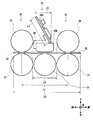
- the discrimination unit 13 clamps at least one of the front end side and the rear end side in the banknote transport direction between the contact point of the transport roller 31 and the tension roller 33 and the contact point of the transport roller 37 and the tension roller 39. Banknotes can be transported stably.
- the short direction length L3 is the distance between the outer peripheral surface of the tension roller 33 of the first transport unit 25 and the outer peripheral surface of the tension roller 39 of the second transport unit 27 along the bill transport direction. It is formed longer than L4. For this reason, the discrimination part 13 cannot arrange
- the conveyance direction substrate length L5 which is the length that the magnetic sensor substrate 34A occupies in the bill conveyance direction, is shorter than the roller outer circumferential surface interval L4. For this reason, the discrimination part 13 can arrange
- the banknote is transported from the transport unit 12 and passes through the transport path 24 inside the discrimination unit 13 from the front or rear of the discrimination unit 13.
- the bills coming from the front of the discrimination unit 13 are sandwiched between the reference roller 41 and the thickness detection roller 42 of the thickness detection unit 29, and a tension spring 45 generates a frictional force at the contact portion between the reference roller 41 and the thickness detection roller 42. Then, it is conveyed to the second conveyance unit 27 by the rotation of the reference roller 41 driven by the conveyance drive motor 60. At this time, the thickness detection roller 42 is displaced by the bill passing through the thickness detection unit 29, and thickness information corresponding to the displacement is transmitted to the discrimination control unit 20 by the displacement sensor 46.
- the optical information of the banknote is transmitted to the discrimination control unit 20 by the light emitting unit 28A and the light receiving unit 28B.
- the banknote that has reached the second transport unit 27 is sandwiched between the tension roller 39 and the transport roller 37 of the second transport unit 27 while being sandwiched between the reference roller 41 and the thickness detection roller 42.
- the bill generates frictional force at the contact portion between the tension roller 39 and the transport roller 37 by the tension spring 39S of the second transport unit 27, and the first transport unit 25 is rotated by the transport roller 37 driven by the transport drive motor 60. It is conveyed to.
- the magnetic detection unit 26 transmits the magnetic information of the banknote to the discrimination control unit 20.
- the banknote that has reached the first transport unit 25 is sandwiched between the tension roller 33 and the transport roller 31 of the first transport unit 25 while being sandwiched between the tension roller 39 and the transport roller 37 of the second transport unit 27.
- the bills generate frictional force at the contact portion between the tension roller 33 and the transport roller 31 by the tension spring 33S of the first transport unit 25, and the rear surface of the discrimination unit 13 by the rotation of the transport roller 31 driven by the transport drive motor 60. From the side to the transport unit 12.
- the distance between the upper transport surface 22A and the lower transport surface 23A is the transport path interval W
- the diameters of the transport roller 31 and the tension roller 33 are the roller diameter D.
- the transport roller 31 and the tension roller 33 are separated from the midpoint of the upper transport surface 22A and the lower transport surface 23A (that is, separated from the upper transport surface 22A to the lower transport surface 23A by W / 2 and from the lower transport surface 23A to W /
- the bill contact angle ⁇ 1 is obtained by the equation (1).
- Equation (1) Since narrowing the conveyance path interval W hinders the conveyance of banknotes, it is confirmed by Equation (1) that the banknote contact angle ⁇ 1 is reduced by increasing the roller diameter D with the conveyance path interval W as a fixed value. it can.
- the discrimination unit 13 includes the tension roller 33, the conveyance roller 31, the guide roller 36, the tension roller 39, the conveyance roller 37 in the first conveyance unit 25, the magnetic detection unit 26, the second conveyance unit 27, and the thickness detection unit 29.
- the diameters of the thickness detection roller 42 and the reference roller 41 are set so that the tension roller 233 in the first conveyance unit 225, the magnetic detection unit 226, the second conveyance unit 227, and the thickness detection unit 229 of the conventional discrimination unit 213 (FIGS. 15 to 17).
- the conveying roller 231, the guide roller 236, the tension roller 239, the conveying roller 237, the thickness detecting roller 242, and the reference roller 241 are made larger.
- the discrimination part 13 can suppress the banknote contact angle of a banknote edge part and a roller smaller than the discrimination part 213, it is based on the deflection of the banknote at the moment of pinching a banknote with a roller, or a collision with a roller and a banknote.
- the impact can be reduced, and the magnetism of the banknote can be accurately read by the magnetic detection element 34B without detecting noise caused by a change in the magnetic field.
- the roller contact point interval L1 needs to be set shorter than the banknote length L2 in the conveyance direction, and therefore the outer diameters of the various rollers of the first conveyance unit 25 and the second conveyance unit 27.
- the roller contact point interval L1 cannot be increased even if the first transfer unit 225 and the second transfer unit 227 are made larger. Therefore, the tension roller 33 and the tension roller 39 are closer to the magnetic sensor 34 than in the case of the tension roller 233 and the tension roller 239, and the length L3 in the short side direction of the substrate is shorter than the distance L4 between the roller outer peripheral surfaces. For this reason, the discrimination part 13 cannot arrange
- the discrimination unit 13 tilts the magnetic sensor substrate 34A from the bill conveyance direction until the conveyance direction substrate length L5 becomes shorter than the roller outer circumferential surface interval L4. Therefore, the discrimination unit 13 can arrange the magnetic sensor substrate 34 ⁇ / b> A between the tension roller 33 and the tension roller 39.
- the discrimination unit 13 is particularly larger in tension roller 33, transport roller 31, tension roller 39, and transport roller 37 than the tension roller 233, transport roller 231, tension roller 239, and transport roller 237 of the conventional discrimination unit 213.
- the magnetic sensor substrate 34A can be accommodated in the upper unit 22 without accurately reading the magnetism of the banknote and without increasing the size of the discrimination section 13 or destabilizing the conveyance of the banknote.
- the discrimination unit 13 causes the tension rollers 33 and 39 to be attached and detached without removing the magnetic detection unit 26 from the upper unit 22 when the tension rollers 33 and 39 are attached to or detached from the upper unit 22.
- the working time can be shortened, and the change in magnetic detection characteristics due to attachment and removal can be prevented.
- the discrimination unit 13 is configured such that the inner ring 33A, the ball 33B and the outer ring 33C of the tension roller 33, and the inner ring 39A, the ball 39B and the outer ring 39C of the tension roller 39 are all made of a nonmagnetic material. As a result, even if the tension roller 33 and the tension roller 39 are close to the magnetic sensor 34, the discrimination unit 13 prevents the tension rollers 33 and 39 from changing the surrounding magnetic field and detects noise caused by the change in the magnetic field. Thus, the magnetism of the banknote can be read with high accuracy by the magnetic detection element 34B.
- the magnetic sensor substrate 234A is fixed to the magnetic detection element 34B by the bracket 250 along the front-rear direction.
- the lead wires 254 ensure the mounting area of these electronic components and the electronic components.
- the magnetic sensor substrate 234A is connected to either end in the front-rear direction so as not to interfere physically and electrically.
- the lead wire 254 connected to the front end portion of the magnetic sensor substrate 234A is curved to the lower surface of the magnetic sensor substrate 234A beyond the front end surface of the magnetic sensor substrate 234A, and the inside of the magnetic detection element 34B.
- the magnetic detection element 34B is electrically connected to the magnetic sensor substrate 34A. For this reason, in the discrimination part 213, the length of the lead wire 254 becomes long, and in particular, a plurality of lead wires 254, for example, 16 pieces are provided along the left-right direction, that is, the width direction of the banknote, so the configuration becomes complicated. I have.
- the discrimination unit 13 is configured to incline the magnetic sensor substrate 34A with respect to the bill conveyance direction, the connecting portion between the lead wire 54 and the magnetic sensor substrate 34A can be brought close to the magnetic detection element 34B.
- the discrimination part 13 can suppress the wiring length of the lead wire 54 compared with the discrimination part 213, and can simplify a structure, ensuring the component mounting area of 34 A of magnetic sensor board
- the discrimination part 13 is arrange
- a plurality of transport rollers 31 and 37 and tension rollers 33 and 39 which are disposed at positions facing the transport rollers 31 and 37 across the transport path 24 and sandwich and transport bills between the transport rollers 31 and 37;
- the discrimination part 13 can read the magnetism of a banknote accurately, storing the magnetic sensor board
- the discrimination unit 113 is compared with the discrimination unit 13 according to the first embodiment, and the magnetic detection unit 26, the first transport unit 25, and the first Although the point which has the magnetic detection part 126 instead of the 2 conveyance part 27, the 1st conveyance part 125, and the 2nd conveyance part 127 is different, it is comprised similarly about another point.
- the first transport unit 125 is different in that it has a tension roller 133 instead of the tension roller 33, but the transport roller 31 and the shaft 32 are configured similarly.
- the tension roller 133 has the same diameter as the tension roller 33 and is formed in an annular shape as a whole, and the shaft 32 penetrates through the center thereof.
- the tension roller 133 is a combination of an inner ring 133A, a ball 133B, an outer ring 133C, and a roller cover 133D, and is configured as a so-called ball bearing.
- the inner ring 133A, the ball 133B, and the outer ring 133C are all made of a magnetic metal material. Although the inner ring 133A has the same inner diameter as the inner ring 33A (FIG. 9), it has a smaller outer diameter. The outer ring 133C has a smaller inner diameter and outer diameter than the outer ring 33C (FIG. 9).
- roller cover 133D On the outside of the outer ring 133C, a roller cover 133D in which a resin, which is a nonmagnetic material, or austenitic stainless steel such as SUS304 or SUS316 is formed in an annular shape is fitted.
- the roller cover 133D has an inner diameter that is substantially equal to the outer diameter of the outer ring 133C, and the outer diameter is substantially equal to that of the outer ring 33C (FIG. 9).
- the tension roller 133 is fixed by the inner ring 133A being inserted through the shaft 32, and the outer ring 133C and the roller cover 133D rotate smoothly together.
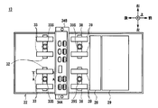
- the magnetic detection unit 126 is configured similarly except that it includes a magnetic sensor 134 instead of the magnetic sensor 34. As shown in FIG. 13 corresponding to FIG. 7, the magnetic sensor 134 is different in that it includes a bracket 150 and a magnetic sensor substrate 134A in place of the bracket 50 and the magnetic sensor substrate 34A, but is otherwise configured in the same manner. Yes.
- the magnetic sensor substrate 134A for controlling the magnetic detection element 34B is fixed to the magnetic detection element 34B via a bracket 150 with the short side direction aligned with the vertical direction.
- the bracket 150 is substantially N-shaped when viewed from the left side, and is formed by bending a metal plate.
- the bracket 150 includes an element holding portion 151 that is in contact with the rear side surface of the magnetic detection element 34B along the vertical direction from the bottom to the top, and is bent at a right angle from the upper end portion of the element holding portion 151 to the front.
- a relay portion 152 in contact with the upper side surface of the magnetic detection element 34B along the front-rear direction, and a magnetic sensor bent from the front end portion of the relay portion 152 at a right angle upward along the arrangement direction of the magnetic sensor substrate 134A toward the upper side.
- the substrate holding portion 153 is in contact with the rear side surface of the substrate 134A.
- the element holding part 151 is formed with an element holding screwing part 151A extending downward from the rear end of the relay part 152 at both ends in the left-right direction. .
- the element holding part 151 is formed with an element holding hollow part 151B in which no metal plate exists between the left element holding screw part 151A and the right element holding screw part 151A.
- an element holding screwing portion 151A is screwed to the magnetic detection element 34B by a screw 151C.
- the substrate holding portion 153 is formed with substrate holding screwing portions 153A extending upward from the front end of the relay portion 152 at both ends in the left-right direction.
- the substrate holding portion 153 is formed with a substrate hollow screwing portion 153B between which the left substrate holding screwing portion 153A and the right substrate holding screwing portion 153A do not exist.
- the substrate holding screwing portion 153A is screwed to the magnetic detection element 134B by a screw 153C. Thereby, the magnetic sensor substrate 134A is fixed to the magnetic detection element 34B in a state perpendicular to the bill conveyance direction.
- a lead wire 154 is connected near the lower end of the front surface of the magnetic sensor substrate 134A.
- the lead wire 154 extends to the vicinity of the lower end portion at a substantially central portion in the front-rear direction inside the magnetic detection element 34B, and electrically connects the magnetic detection element 34B and the magnetic sensor substrate 134A.
- the second transport unit 127 is different in that it has a tension roller 139 instead of the tension roller 39, but the transport roller 37 and the shaft 38 are configured similarly.
- the tension roller 139 includes an inner ring 139A, a ball 139B, and an outer ring 139C formed of a magnetic material, and a roller cover 139D formed of a nonmagnetic material and fitted outside the outer ring 139C. ing.
- the discrimination unit 113 sets the magnetic sensor substrate 134A in a state perpendicular to the bill conveyance direction. Therefore, the discrimination unit 113 can arrange the magnetic sensor substrate 134 ⁇ / b> A between the tension roller 133 and the tension roller 139.
- the discrimination unit 113 makes the outer diameter of the outer ring 133C in the tension roller 133 smaller than the outer diameter of the outer ring 33C, and fits the roller cover 133D outside the outer ring 133C, so that the apparent outer diameter of the tension roller 133 is increased.
- the diameter was made equal to that of the tension roller 33.
- the discrimination unit 113 can separate the outer peripheral surfaces of the tension rollers 133 and 139 made of a magnetic material from the magnetic sensor 134 more than the tension rollers 33 and 39, respectively. As a result, the discrimination unit 113 can suppress the change in the magnetic field applied to the magnetic sensor 134 by the tension rollers 133 and 139, suppress noise caused by the change in the magnetic field, and accurately read the magnetism of the bill by the magnetic detection element 34B. it can.
- a ball bearing made of a magnetic material can have higher durability than a ball bearing made of a non-magnetic material.
- the discrimination unit 113 suppresses the influence of the change in the magnetic field on the magnetic sensor 134 due to the tension rollers 133 and 139 being made of a magnetic material, and the tension rollers 133 and 139 than the tension rollers 33 and 39 of the discrimination unit 13. Can increase the durability.
- the discrimination unit 113 is provided with the magnetic sensor substrate 134A perpendicular to the bill conveyance direction, the connecting portion between the lead wire 154 and the magnetic sensor substrate 134A is made closer to the magnetic detection element 34B than the discrimination unit 13 is. be able to. As a result, the discrimination unit 113 can further reduce the length of the lead wire 154 than that of the discrimination unit 13 and can simplify the configuration while securing a component mounting area of the magnetic sensor substrate 134A having a limited size. .
- the vibration caused by the bills being conveyed is mainly vibration along the vertical direction.
- the discrimination unit 113 aligns the position where the screw 153C, which is a fulcrum for fixing the magnetic sensor substrate 134A, and the center of gravity of the magnetic sensor substrate 134A substantially in the vertical direction, thereby making the magnetic sensor more than the discrimination unit 13. The vibration of the substrate 134A can be suppressed.
- the discrimination unit 113 according to the second embodiment exhibits substantially the same operation and effect as the discrimination unit 13 according to the first embodiment.
- the magnetic sensor substrate 34A is fixed with an inclination of about 30 degrees from the up-down direction, which is a direction perpendicular to the bill conveyance direction, toward the rear.
- the present invention is not limited to this, and the magnetic sensor substrate 34 ⁇ / b> A may be fixed by inclining forward from the vertical direction, which is a direction perpendicular to the bill conveyance direction.
- the present invention is applied to the magnetic sensor 34 in the above-described embodiment.
- the present invention is not limited to this, and the present invention may be applied to various other sensors that control the detection element with a substrate.
- the magnetic sensor 34, the 1st conveyance part 25, and the 2nd conveyance part 27 of 1st Embodiment, and the magnetic sensor 134, the 1st conveyance part 125, and the 2nd conveyance part 127 of 2nd Embodiment are included. You may select and combine suitably.
- the modules such as the first transport unit 25, the magnetic detection unit 26, the second transport unit 27, the optical detection unit 28, and the thickness detection unit 29 are provided in the discrimination unit 13.
- the present invention is not limited to this, and it is sufficient that the discrimination unit 13 can discriminate the type, authenticity, and the like of the banknote based on at least the magnetic detection result in the magnetic detection unit 26, and the optical detection unit 28 according to the discrimination method.
- the thickness detector 29 and the like, and further, the respective transport units may be appropriately combined. The same applies to the second embodiment.
- the discrimination process was performed about the banknote as a medium in the discrimination part 13 of the automatic teller machine 1 which transactions cash, such as a banknote.
- the present invention is not limited to this, and may be applied to various devices that perform a discrimination process on a magnetic medium having various shapes such as a gift certificate, a cash voucher, an admission ticket, or a magnetic card.
- a magnetic medium having various shapes such as a gift certificate, a cash voucher, an admission ticket, or a magnetic card.
- the conveyance path 24 in the conveyance part 12, the discrimination part 13, etc. according to the shape of a medium. The same applies to the second embodiment.
- the case where the discrimination units 13 and 113 as the medium discrimination device are configured by the magnetic sensor substrates 34A and 134A as the partial substrates has been described.
- the present invention is not limited to this, and a medium discrimination device may be configured by a feature detection unit, a transport roller, a counter roller, and a feature detection unit substrate having various other configurations.
- the customer reception unit 3 as a customer reception unit
- the magnetic detection units 26 and 126 as feature detection units
- the conveyance rollers 31 and 37 as conveyance rollers
- the tension roller as an opposing roller
- automatic cash transaction apparatuses 1 and 101 as medium transaction apparatuses are configured by 33 and 39, 133 and 139, and magnetic sensor substrates 34A and 134A as characteristic detection unit boards.
- the present invention is not limited to this, and a medium transaction apparatus may be configured by a customer reception unit, a feature detection unit, a transport roller, a counter roller, and a feature detection unit substrate having various other configurations.
- the present invention can also be used in various media discrimination devices that discriminate by detecting the magnetism while conveying a magnetized medium.
Landscapes
- Physics & Mathematics (AREA)
- General Physics & Mathematics (AREA)
- Inspection Of Paper Currency And Valuable Securities (AREA)
Applications Claiming Priority (2)
| Application Number | Priority Date | Filing Date | Title |
|---|---|---|---|
| JP2014-257655 | 2014-12-19 | ||
| JP2014257655A JP6455131B2 (ja) | 2014-12-19 | 2014-12-19 | 媒体鑑別装置及び媒体取引装置 |
Publications (1)
| Publication Number | Publication Date |
|---|---|
| WO2016098427A1 true WO2016098427A1 (ja) | 2016-06-23 |
Family
ID=56126329
Family Applications (1)
| Application Number | Title | Priority Date | Filing Date |
|---|---|---|---|
| PCT/JP2015/078544 Ceased WO2016098427A1 (ja) | 2014-12-19 | 2015-10-07 | 媒体鑑別装置及び媒体取引装置 |
Country Status (2)
| Country | Link |
|---|---|
| JP (1) | JP6455131B2 (enExample) |
| WO (1) | WO2016098427A1 (enExample) |
Families Citing this family (2)
| Publication number | Priority date | Publication date | Assignee | Title |
|---|---|---|---|---|
| JP6828456B2 (ja) * | 2017-01-23 | 2021-02-10 | 沖電気工業株式会社 | 媒体処理装置 |
| JP7131148B2 (ja) | 2018-07-11 | 2022-09-06 | セイコーエプソン株式会社 | 媒体搬送装置、及び媒体処理装置 |
Citations (4)
| Publication number | Priority date | Publication date | Assignee | Title |
|---|---|---|---|---|
| JPH1011631A (ja) * | 1996-06-27 | 1998-01-16 | Toshiba Corp | 紙幣鑑査装置及び紙幣鑑査装置の補正方法 |
| JP5375912B2 (ja) * | 2011-09-22 | 2013-12-25 | 沖電気工業株式会社 | 媒体鑑別装置及び媒体取引装置 |
| JP2014067794A (ja) * | 2012-09-25 | 2014-04-17 | Nec Corp | 実装構造体及び実装構造体の製造方法 |
| WO2014069251A1 (ja) * | 2012-10-31 | 2014-05-08 | 富士フイルム株式会社 | カメラモジュール |
-
2014
- 2014-12-19 JP JP2014257655A patent/JP6455131B2/ja active Active
-
2015
- 2015-10-07 WO PCT/JP2015/078544 patent/WO2016098427A1/ja not_active Ceased
Patent Citations (4)
| Publication number | Priority date | Publication date | Assignee | Title |
|---|---|---|---|---|
| JPH1011631A (ja) * | 1996-06-27 | 1998-01-16 | Toshiba Corp | 紙幣鑑査装置及び紙幣鑑査装置の補正方法 |
| JP5375912B2 (ja) * | 2011-09-22 | 2013-12-25 | 沖電気工業株式会社 | 媒体鑑別装置及び媒体取引装置 |
| JP2014067794A (ja) * | 2012-09-25 | 2014-04-17 | Nec Corp | 実装構造体及び実装構造体の製造方法 |
| WO2014069251A1 (ja) * | 2012-10-31 | 2014-05-08 | 富士フイルム株式会社 | カメラモジュール |
Also Published As
| Publication number | Publication date |
|---|---|
| JP2016118896A (ja) | 2016-06-30 |
| JP6455131B2 (ja) | 2019-01-23 |
Similar Documents
| Publication | Publication Date | Title |
|---|---|---|
| JP5375912B2 (ja) | 媒体鑑別装置及び媒体取引装置 | |
| CN105122319B (zh) | 介质聚集装置和介质处理装置 | |
| JP6369114B2 (ja) | 鑑別装置及び媒体取引装置 | |
| CN105900154A (zh) | 介质蓄积装置和介质交易装置 | |
| CN106170825B (zh) | 厚度检测装置和介质交易装置 | |
| JP2014047073A (ja) | 厚み検出装置及び媒体取引装置 | |
| JP2014058396A (ja) | 厚み検知装置 | |
| CN104854628B (zh) | 自动交易装置 | |
| JP6131583B2 (ja) | 自動取引装置 | |
| CN105392721B (zh) | 介质输送装置和介质交易装置 | |
| JP6455131B2 (ja) | 媒体鑑別装置及び媒体取引装置 | |
| JP6064791B2 (ja) | 媒体繰出装置及び媒体処理装置 | |
| JP7419735B2 (ja) | 媒体鑑別装置及び媒体取扱装置 | |
| JP6544068B2 (ja) | 媒体鑑別装置及び自動取引装置 | |
| JP5472523B2 (ja) | 媒体鑑別装置及び媒体取引装置 | |
| JP5853717B2 (ja) | 厚み検出装置 | |
| CN106663350A (zh) | 介质收容装置和介质交易装置 | |
| JP6237911B2 (ja) | 媒体搬送識別装置及び媒体取引装置 | |
| JP6303898B2 (ja) | 媒体鑑別装置及び媒体処理装置 | |
| WO2015040901A1 (ja) | 媒体繰出装置及び媒体取引装置 | |
| JP6707971B2 (ja) | 紙葉状媒体鑑別装置及び自動取引装置 | |
| JP2016204083A (ja) | 媒体搬送装置及び媒体取引装置 | |
| JP2019061354A (ja) | 媒体処理装置及び自動取引装置 |
Legal Events
| Date | Code | Title | Description |
|---|---|---|---|
| 121 | Ep: the epo has been informed by wipo that ep was designated in this application |
Ref document number: 15869635 Country of ref document: EP Kind code of ref document: A1 |
|
| NENP | Non-entry into the national phase |
Ref country code: DE |
|
| 122 | Ep: pct application non-entry in european phase |
Ref document number: 15869635 Country of ref document: EP Kind code of ref document: A1 |