WO2016093252A1 - Dispositif de test de passage pour un dispositif médical à long corps, et procédé pour évaluer le passage d'un dispositif médical à long corps - Google Patents
Dispositif de test de passage pour un dispositif médical à long corps, et procédé pour évaluer le passage d'un dispositif médical à long corps Download PDFInfo
- Publication number
- WO2016093252A1 WO2016093252A1 PCT/JP2015/084449 JP2015084449W WO2016093252A1 WO 2016093252 A1 WO2016093252 A1 WO 2016093252A1 JP 2015084449 W JP2015084449 W JP 2015084449W WO 2016093252 A1 WO2016093252 A1 WO 2016093252A1
- Authority
- WO
- WIPO (PCT)
- Prior art keywords
- medical
- hole
- passage
- load
- passability
- Prior art date
Links
Images


Classifications
-
- G—PHYSICS
- G09—EDUCATION; CRYPTOGRAPHY; DISPLAY; ADVERTISING; SEALS
- G09B—EDUCATIONAL OR DEMONSTRATION APPLIANCES; APPLIANCES FOR TEACHING, OR COMMUNICATING WITH, THE BLIND, DEAF OR MUTE; MODELS; PLANETARIA; GLOBES; MAPS; DIAGRAMS
- G09B23/00—Models for scientific, medical, or mathematical purposes, e.g. full-sized devices for demonstration purposes
- G09B23/28—Models for scientific, medical, or mathematical purposes, e.g. full-sized devices for demonstration purposes for medicine
- G09B23/285—Models for scientific, medical, or mathematical purposes, e.g. full-sized devices for demonstration purposes for medicine for injections, endoscopy, bronchoscopy, sigmoidscopy, insertion of contraceptive devices or enemas
-
- G—PHYSICS
- G09—EDUCATION; CRYPTOGRAPHY; DISPLAY; ADVERTISING; SEALS
- G09B—EDUCATIONAL OR DEMONSTRATION APPLIANCES; APPLIANCES FOR TEACHING, OR COMMUNICATING WITH, THE BLIND, DEAF OR MUTE; MODELS; PLANETARIA; GLOBES; MAPS; DIAGRAMS
- G09B19/00—Teaching not covered by other main groups of this subclass
- G09B19/24—Use of tools
-
- G—PHYSICS
- G09—EDUCATION; CRYPTOGRAPHY; DISPLAY; ADVERTISING; SEALS
- G09B—EDUCATIONAL OR DEMONSTRATION APPLIANCES; APPLIANCES FOR TEACHING, OR COMMUNICATING WITH, THE BLIND, DEAF OR MUTE; MODELS; PLANETARIA; GLOBES; MAPS; DIAGRAMS
- G09B23/00—Models for scientific, medical, or mathematical purposes, e.g. full-sized devices for demonstration purposes
- G09B23/28—Models for scientific, medical, or mathematical purposes, e.g. full-sized devices for demonstration purposes for medicine
- G09B23/30—Anatomical models
- G09B23/32—Anatomical models with moving parts
-
- G—PHYSICS
- G09—EDUCATION; CRYPTOGRAPHY; DISPLAY; ADVERTISING; SEALS
- G09B—EDUCATIONAL OR DEMONSTRATION APPLIANCES; APPLIANCES FOR TEACHING, OR COMMUNICATING WITH, THE BLIND, DEAF OR MUTE; MODELS; PLANETARIA; GLOBES; MAPS; DIAGRAMS
- G09B9/00—Simulators for teaching or training purposes
Definitions
- the present invention relates to a medical elongate passability test apparatus and a medical elongate passability evaluation method performed using the medical elongate passability test apparatus.
- PTCA percutaneous transaneous coronary angioplasty
- the lesion model is made of silicon resin or the like and is a simulated reproduction of a stenosis or occlusion state of a blood vessel.
- the performance related to the passage of a medical long body such as a balloon catheter is evaluated by a sensory test conducted by a doctor using the above lesion model. Since the sensory test is based on the subjective impression of the individual, it cannot be said that the performance regarding the passability of the medical long body is accurately evaluated without variation.
- the present invention has been made in order to meet the above-described demand, and provides a medical elongate passage test apparatus that can objectively evaluate the performance of the medical elongate passage. Objective. It is another object of the present invention to provide a method for evaluating the passability of a medical long body using the medical long body passability test apparatus.
- a medical elongate body passage test apparatus that achieves the above object includes a main body portion having a hole portion through which the medical elongate body can be inserted, and the medical elongate body inserted into the hole portion. And at least one obstacle portion that hinders passage by a load (F) having a known size.
- the obstructing part protrudes into the hole part so as to be retractable from the hole part and contacts the medical elongated body, and a load acting in a direction to project the movable part into the hole part.
- a load section that loads the load.
- the medical elongate passability evaluation method that achieves the above object is a medical elongate passability evaluation method performed using the medical elongate passability test apparatus described above, wherein the hole When the medical long body inserted into the part can pass through the movable part by retreating the movable part from the hole part, it is evaluated that “it has a permeability to a load (F) whose size is known”.
- the medical elongate passability test can be performed by adjusting the load (F) that obstructs the passage of the medical elongate body. It is possible to objectively evaluate the performance of the medical elongated body without regard to the individual's subjective impression, and to improve the accuracy of the performance evaluation of the medical elongated body. Become.
- the performance of the medical long body can be objectively evaluated without depending on the subjective impression of the individual. It is possible to improve the accuracy of the performance evaluation of the medical long body.
- FIG. 2A and 2B are a front view and a rear view showing a medical elongate body permeability test apparatus.
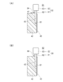
- 3A and 3B are cross-sectional views taken along line 3-3 in FIG. 2A, and FIG. 3A shows the first position where the movable portion narrows the hole.
- FIG. 3B is a cross-sectional view showing a state in which the movable portion protrudes to the second position where the hole portion is closed.
- 4 (A), 4 (B), and 4 (C) are enlarged views of a main part of FIG.
- FIG. 10 is a front view showing a medical elongate passage test apparatus according to a modification, which is a medical elongate passage test apparatus in which the axis of a hole extends in a curved shape. It is a medical elongate passage test device concerning other modifications, and is an important section enlarged view showing composition of an obstacle part.
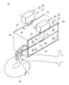
- FIG. 1 is a view showing a state where a balloon catheter 30 as a medical elongated body 30 is subjected to a permeability test using the medical elongated body permeability test apparatus 10 according to an embodiment of the present invention.
- 2 (A) and 2 (B) are a front view and a rear view showing the passability test apparatus 10 for the medical elongated body 30, and
- FIGS. 3 (A) and 3 (B) are lines 3-3 in FIG. 2 (A).
- 3A is a cross-sectional view showing a state where the movable portion 51 protrudes to the first position S1 where the hole 41 is constricted
- FIG. 3B is a view showing the movable portion.
- FIG. 4 (A), 4 (B), and 4 (C) are enlarged views of the main part of FIG. 2 (A) showing a state in which the passability test of the medical elongated body 30 is performed.
- FIG. 4B shows a state in which the distal end of the medical long body 30 has reached the movable part 51
- FIG. 4B shows a state in which the medical long body 30 has moved away from the hole part 41 and passed through the movable part 51.
- FIG. 4C is a diagram illustrating a state in which the medical long body 30 cannot pass through the movable portion 51.
- the passability test apparatus 10 (hereinafter also simply referred to as “test apparatus 10”) of the medical long body 30 is generally a hole through which the medical long body 30 can be inserted. At least one that obstructs the passage of the body portion 40 in which the portion 41 (generic name of 61, 71) and the medical elongated body 30 inserted into the hole portion 41 are loaded by a load (F) whose size is known.
- a load whose size is known.
- Two obstacles 50 protrudes into the hole part 41 so as to be retractable from the hole part 41 and contacts the medical long body 30 and a load acting in a direction in which the movable part 51 protrudes into the hole part 41.
- a load portion 52 that loads the movable portion 51.
- the end of the blood vessel model 20 can be freely connected to the hole 41, and the test apparatus 10 performs a passability test of the medical elongated body 30 inserted into the hole 41 through the blood vessel model 20. It is configured to be possible.
- a balloon catheter 30 will be described as an example of the medical long body 30. Details will be described below.
- the right front side of the test apparatus 10 is a front surface, and the opposite left hand back side is a back surface.
- the main body 40 of the test apparatus 10 is provided with a plurality of combinations of the hole 41 and the obstacle 50. As a result, the test apparatus 10 can perform a plurality of types of passability tests on one balloon catheter 30.
- a first test unit 60 (see FIG. 2A) disposed on the front side and a second test unit 70 (FIG. 2B) disposed on the back side are provided. 2 types) are provided.
- the first test part 60 has a bump-like convex part 71a in which the hole 71 protrudes toward the obstacle part 50 in that the axis of the hole 61 extends linearly, and the axis of the hole 71 is This is different from the second test portion 70 that extends partially in a curved shape.
- the first test unit 60 is different from the second test unit 70 having a pointed shape in that the portion of the obstacle 50 that contacts the balloon catheter 30 has a flat shape.
- the main body part 40 includes a base part 42, a first cover part 43 attached to the front side of the base part 42, and a second cover part 44 attached to the back side of the base part 42.
- the 1st cover part 43 and the 2nd cover part 44 are formed from the transparent body so that the situation where the balloon catheter 30 passes the obstruction part 50 can be visually recognized.
- By forming at least a part of the main body portion 40 from a transparent body it is possible to visually recognize the passage state of the balloon catheter 30 and to reliably and easily determine whether or not the balloon catheter 30 has passed.
- the movable part 51 in the first test part 60 and the second test part 70 includes movable plates 62 and 72 that are slidably provided on the main body part 40 and have known masses. Yes.
- the load unit 52 in the first test unit 60 and the second test unit 70 includes weights 63 and 73 attached to the movable plates 62 and 72 and having a known mass.
- Mass of movable plate 62 in first test unit 60 m11 [kg] Mass of weight 63 in first test unit 60: m12 [kg] Mass of movable plate 72 in second test unit 70: m21 [kg] The mass of the weight 73 in the second test unit 70 is m22 [kg].
- the obstacle unit 50 greatly increases the passage of the balloon catheter 30 inserted into the hole 61. Is inhibited by a known load (F1). Also in the second test unit 70, the obstacle unit 50 inhibits the passage of the balloon catheter 30 inserted into the hole 71 by a load (F2) whose size is known.
- F2 (m21 + m22) ⁇ G [N]
- G is a gravitational acceleration. It becomes.
- the weights 63 and 73 are not particularly limited, but for example, a plurality of weights 63 and 73 are manufactured within a range of 1 gram to 500 grams. A plurality of weights may be manufactured so that the weight difference between the weights is equal, or a plurality of weights may be manufactured so that the weight difference between the weights gradually increases. Insertion holes are formed in the lower surfaces of the weights 63 and 73. The weights 63 and 73 can be inserted into the upper end portions of the movable plates 62 and 72 in a replaceable manner.
- the movable plates 62 and 72 are inserted into the longitudinal grooves 45 and 46 formed in the base portion 42 of the main body 40 from the upper surface of the main body 40.
- the movable plates 62 and 72 are slid and guided by the vertical grooves 45 and 46.
- the clearance between the movable plates 62 and 72 and the longitudinal grooves 45 and 46 is set to be slightly larger, and the sliding surface is finished to be a smooth surface. .
- the material for forming the main body 40 and the material for forming the movable plates 62 and 72 are resin materials from the viewpoint of reducing the sliding resistance of the balloon catheter 30 in the holes 61 and 71 and the sliding resistance of the movable plates 62 and 72. Or a metal material.
- the resin material include acrylic resin, polycarbonate resin, and hard vinyl chloride resin.
- the metal material include aluminum and stainless steel.
- the forming material of the first cover portion 43 and the second cover portion 44 is selected from materials having transparency and low friction with respect to the balloon catheter 30.
- Examples of the forming material include acrylic resin and glass.
- the test apparatus 10 includes a passability test when the balloon catheter 30 passes through the stenotic hole 61 (hereinafter referred to as a “stenosis type passability test”).
- a passability test when the balloon catheter 30 passes through the closed hole 61 (hereinafter, referred to as an “occlusion type passability test”) can be performed.
- the movable plate 62 has a first position S1 (FIG. 3A) where the hole 61 is constricted, or a second position where the hole 61 is closed. It protrudes to any position in the position S2 (FIG. 3B).
- a spacer 47 is disposed on the upper surface of the base portion 42 so as to abut against the stopper 64 of the movable plate 62.
- the stopper 64 of the movable plate 62 contacts the spacer 47, a gap is generated between the lower portion of the movable plate 62 and the lower surface of the hole 61.
- the movable plate 62 protrudes to the first position S1 where the hole 61 is constricted.
- the gap dimension between the lower portion of the movable plate 62 and the lower surface of the hole 61 can be selected, and the first position S1 can be selected from a plurality of positions. You may do it.
- the spacer 47 is not arranged on the upper surface of the base portion 42 when the blocking type passability test is performed.
- the stopper 64 of the movable plate 62 does not contact the upper surface of the base portion 42, and the lower portion of the movable plate 62 contacts the lower surface of the hole portion 61. Thereby, the movable plate 62 protrudes to the second position S2 that closes the hole 61.
- the movable plate 72 of the second test unit 70 is also provided with a stopper 74. Similarly to the movable plate 62, the first position where the hole 71 is constricted or the first position where the hole 71 is closed. Projects to any of the two positions.
- the movable plate 62 in the first test unit 60 has a rough surface portion 65 imitating a calcified lesion of a blood vessel at a site where the balloon catheter 30 contacts.
- the surface roughness of the rough surface portion 65 is not particularly limited. Moreover, since the rough surface part 65 imitates a calcified lesion part, it is preferable to form it from a comparatively hard material instead of a soft material.
- the rough surface portion 65 may be formed by fixing a material having a predetermined surface roughness to the movable plate 62, or the surface may be roughened by processing a part of the movable plate 62. .
- the lower end corner of the movable plate 62 is formed in a rounded surface on the left side in the drawing and a vertical surface orthogonal to the axis of the hole 61 in the right side in the drawing.
- the vertical surface can be positioned on the left side in the drawing and the round surface can be positioned on the right side in the drawing, contrary to the illustrated example.
- the rounded surface or the vertical surface can be selectively opposed to the balloon catheter 30 inserted from the left side in the drawing. Therefore, the penetrability test of the balloon catheter 30 with respect to the rounded surface can be performed, or the penetrability test of the balloon catheter 30 with respect to the vertical surface, which is a stricter condition than the rounded surface, can be performed.
- the balloon catheter 30 may be inserted from the right side in the figure.
- an inclined surface that is inclined with respect to the axis of the hole 61 may be used.
- a plurality of movable plates 62 having inclined surfaces with different inclination angles with respect to the axis of the hole 61 may be manufactured.
- the penetrability test of the balloon catheter 30 can be performed on a shape approximate to the end shape of an actual stenosis site or occlusion site.
- stoppers 64 on both the front and back surfaces of the movable plate 62. Even when the direction of the movable plate 62 is reversed and inserted into the longitudinal groove 45, the movable plate 62 is moved to the first position S1 where the hole 61 is constricted or the second position where the hole 61 is closed. This is because it can be projected to any position of the position S2.
- the axis of the hole 61 in the first test part 60 extends linearly.
- the axis of the hole 71 in the second test portion 70 extends in a straight line except for the convex portion 71a, and extends in a curved or meandering manner so as to form a semicircular arc in the convex portion 71a.
- the cross-sectional shape of the holes 61 and 71 is not particularly limited, and an appropriate shape such as a circular shape, an elliptical shape, or a rectangular shape can be adopted.
- the sizes of the holes 61 and 71 may be larger than the outer diameter of the balloon catheter 30 that performs the passability test in order to reduce the frictional resistance until the obstacle 50 is reached.
- the size of the holes 61 and 71 is not particularly limited, but is preferably set to about 0.1 to 8.0 mm, and more preferably about 1.0 to 5.0 mm.
- the axes of the holes 61 and 71 extend two-dimensionally.
- the insertion passage of the balloon catheter 30 formed by the holes 61 and 71 can be shaped to reduce frictional resistance as much as possible.
- the hole 71 has a bump-shaped convex part 71a protruding toward the obstacle part 50. This convex part 71a imitates the calcified bump raised on the inner surface of the blood vessel.
- the main body 40 is set so that the movable plate 62 moves in the vertical direction, and the balloon catheter 30 is inserted into the hole 61 through the blood vessel model 20.
- the balloon catheter 30 is pushed forward and brought into contact with the movable plate 62.
- the balloon catheter 30 is further pushed forward, and the balloon catheter 30 pushes up the movable plate 62 and retreats from the hole 61 to pass therethrough.
- the weight 63 was replaced with a heavy weight 63 (mass of the weight 63: m13, m14,... M1x, m1y,...), And the weight 63 was inserted into the hole 61 while changing the load applied to the movable plate 62. It is repeatedly checked whether or not the balloon catheter 30 has retreated from the hole 61 and passed through the movable plate 62.
- the performance relating to the passage of the balloon catheter 30 can be objectively evaluated without depending on the subjective impression of the individual, and the accuracy of the performance evaluation of the balloon catheter 30 can be improved. Is possible.
- the test apparatus 10 includes the main body 40 in which the holes 61 and 71 into which the balloon catheter 30 can be inserted and the balloon catheter 30 inserted into the holes 61 and 71. And at least one obstacle 50 that inhibits passage by a load (F) having a known size.
- the obstruction part 50 acts in a direction in which the movable part 51 protrudes into the hole parts 61 and 71 and the movable part 51 protrudes into the hole parts 61 and 71 and comes into contact with the balloon catheter 30, and the movable part 51 projects into the hole parts 61 and 71 And a load portion 52 that loads the movable portion 51 with a load to be performed.
- the load (F) that inhibits the passage of the balloon catheter 30 can be adjusted to perform a passage test of the balloon catheter 30, and the performance related to the passage of the balloon catheter 30 can be objectively evaluated without depending on the subjective impression of the individual.
- the accuracy of performance evaluation of the balloon catheter 30 can be improved.
- the movable portion 51 includes movable plates 62 and 72 that are slidably provided on the main body portion 40 and have a known mass.
- the load portion 52 is attached to the movable plates 62 and 72 and has weights 63 and 73 that have a known mass. It is composed of By changing or adding the weights 63 and 73, the load (F) that inhibits the passage of the balloon catheter 30 can be adjusted, and the passage of the balloon catheter 30 can be tested.
- the movable portion 51 protrudes to either the first position S1 where the holes 61 and 71 are constricted or the second position S2 where the holes 61 and 71 are closed.
- a stenosis type permeability test and an occlusion type permeability test can be performed, and the permeability of the balloon catheter 30 can be tested in either a stenosis state or an occlusion state.
- the movable portion 51 has a rough surface portion 65 imitating a calcified lesion of a blood vessel at a site where the balloon catheter 30 contacts. Thereby, the passability of the balloon catheter 30 in the state where the calcified lesion part of the blood vessel exists can be tested.
- the axis of the holes 61 and 71 extends linearly or curvedly.
- the axes of the holes 61 and 71 extend in two dimensions. Thereby, the passage of the balloon catheter 30 can be tested in a shape in which the frictional resistance of the insertion passage of the balloon catheter 30 formed by the holes 61 and 71 is reduced.
- the hole portion 71 has a bump-shaped convex portion 71 a that protrudes toward the obstacle portion 50.
- a calcified bump raised on the inner surface of the blood vessel can be simulated, and the passage of the balloon catheter 30 in a state where the bump is present can be tested.
- At least a part of the main body 40 is formed of a transparent body so that the situation where the balloon catheter 30 passes through the obstacle 50 can be visually confirmed. Since the passage condition of the balloon catheter 30 can be visually confirmed, it is possible to reliably and easily determine whether or not the balloon catheter 30 has passed.
- the main body portion 40 is provided with a plurality of combinations of the hole portions 61 and 71 and the obstacle portion 50, and a plurality of types of passability tests can be performed on one balloon catheter 30.
- One main body 40 can be shared for a plurality of types of passability tests, and the cost of the test apparatus 10 can be reduced.
- the end portions of the blood vessel model 20 can be freely connected to the hole portions 61 and 71, and a passability test of the balloon catheter 30 inserted through the blood vessel model 20 and inserted into the hole portions 61 and 71 can be performed. Thereby, the passability of the balloon catheter 30 considering the frictional resistance in the blood vessel can be tested.
- the medical elongate body 30 is a balloon catheter 30, the passability of the balloon catheter 30 frequently used in PTCA or the like is tested, and an objective performance evaluation result of the balloon catheter 30 is provided to a doctor or the like. be able to.
- the balloon catheter 30 inserted into the hole portions 61 and 71 was able to pass through the movable portion 51 retracted from the hole portions 61 and 71.
- the size has a permeability to a known load (F)”. This makes it possible to objectively evaluate the performance related to the passability of the balloon catheter 30 without depending on an individual's subjective impression, and it is possible to improve the accuracy of performance evaluation of the balloon catheter 30.
- the maximum load (Fmax) having passability is evaluated. This makes it possible to objectively evaluate the maximum performance related to the passage of the balloon catheter 30 without depending on the subjective impression of the individual.
- FIG. 5 shows the passability test apparatus 10 for the medical elongated body 30 according to the modified example, in which the axial lines of the holes 61 and 71 extend in a curved shape.
- FIG. Members common to the embodiment of FIGS. 1 to 4 are denoted by the same reference numerals, and a description thereof is partially omitted.
- the test apparatus 10 according to the modified example is different from the first test unit 60 of the embodiment in which the axis of the hole 61 extends linearly in that the axis of the hole 81 extends in a curved shape.
- the second test unit 70 is different from the second test unit 70 in that the degree of curvature is larger (severe) than the hole 71.
- the test apparatus 10 opens an insertion port on the upper surface of the main body 40 and forms a second hole 81 communicating with the hole 61.
- the propulsive force of the balloon catheter 30 is greatly lost at the bending point 82 in the figure. Therefore, the penetrability test of the balloon catheter 30 can be performed under severe conditions as compared with the hole 61 of the first test unit 60.
- FIG. 6 is a main part enlarged view showing the configuration of the obstacle 50 in the passability test apparatus 10 for the medical elongated body 30 according to another modification.
- Members common to the embodiment of FIGS. 1 to 4 are denoted by the same reference numerals, and a description thereof is partially omitted.
- the obstacle 50 in the test apparatus 10 is configured such that the weights 63 and 73 are configured such that passage of the balloon catheter 30 is inhibited by a load (F) whose size is known by the fluid pressure of the working fluid.
- a load (F) whose size is known by the fluid pressure of the working fluid.
- the obstacle 50 of the test apparatus 10 includes a movable part 51 that protrudes into the hole 91 so as to be retractable from the hole 91 and contacts the balloon catheter 30, and a movable part 51. And a load portion 52 that loads the movable portion 51 with a load acting in a direction of projecting into the hole portion 91.
- the movable portion 51 includes an inflatable body 92 that expands and is flexible when a working fluid is supplied.
- the load unit 52 includes a working fluid supply unit 93 that supplies a working fluid having a known pressure to the expansion body 92.
- the expansion body 92 is stored in a storage chamber 94 formed in the main body 40.
- the upper surface opening of the storage chamber 94 is closed with a lid member 95 attached.
- a cap 96 that comes into contact with the balloon catheter 30 is attached to the lower end portion of the inflatable body 92.
- the pressure receiving area (A [m 2 ]) of the cap 96 is known.
- the cap 96 is made of a material that does not deform even when the pressure of the working fluid acts.
- the working fluid supply unit 93 includes, for example, a cylinder 97 filled with a high-pressure working fluid and a regulator valve 98 capable of adjusting the pressure of the working fluid supplied from the cylinder 97, and the expansion body 92 is connected via a pipe 99. Connected with the inside.
- a compressor may be used, by using the cylinder 97, the configuration of the test apparatus 10 becomes simple and small, and it is easy to carry and carry.
- As the working fluid it is preferable to use a gas such as air or nitrogen because it is easy to handle.
- the obstacle 50 inhibits the passage of the balloon catheter 30 inserted into the hole 91 by a load (F3) having a known size.
- the masses of the expanding body 92 and the cap 96 are ignored.
- the movable portion 51 includes the expansion body 92 that is expanded and flexible when supplied with the working fluid
- the load portion 52 includes the working fluid whose pressure is known. It is comprised from the working fluid supply part 93 which supplies the expansion body 92 with.
- the load can be continuously and easily changed from a large load to a small load or from a small load to a large load.
- the load for testing the passability can be finely adjusted continuously, not stepwise, and the performance of the balloon catheter 30 regarding the passability can be objectively and finely evaluated. can do.
- a pin protruding from the cap 96 is protruded to the outside of the main body 40 (the front side in FIG. 6), and a spacer is brought into contact with the protruding pin so that the cap 96
- the descent limit position can be regulated. Accordingly, the cap 96 can be protruded to either the first position where the hole 91 is constricted or the second position where the hole 91 is closed.
- test apparatus 10 provided with only one obstacle 50 for one hole 61, 71, 91 has been described, the present invention is not limited to this case. Two or more obstacles 50 can be provided for one hole 61, 71, 91. Compared to the case where only one obstacle 50 is provided, the penetrability test of the balloon catheter 30 can be performed under more severe conditions.
- test apparatus 10 having a flat shape (first test unit 60, modified examples, other modified examples) and a pointed shape (second test unit 70) in a portion of the obstacle unit 50 that contacts the balloon catheter 30.
- first test unit 60 modified examples, other modified examples
- second test unit 70 pointed shape
- the portion that contacts the balloon catheter 30 may have a rounded shape.
- the present invention is not limited to this case.
- the axis of the hole may extend in three dimensions.
- the penetrability test of the balloon catheter 30 can be performed under more severe conditions than in the case where the axes of the holes 61, 71, 91 extend in two dimensions.
- the entire main body 40 is preferably formed from a transparent body. This is because, by forming the entire main body 40 from a transparent body, it is possible to easily confirm the passage of the balloon catheter 30 in the three-dimensionally extending hole.
- the balloon catheter 30 can be directly inserted into the main body portion 40 and a passability test can be performed.
- a resistance portion that becomes resistance when the balloon catheter 30 passes can be provided at an upstream position in the direction in which the balloon catheter 30 is inserted with respect to the obstacle portion 50.
- the resistance portion can be formed by forming a narrowed or closed hole in a main body formed of an elastic material.
- the resistance in the resistance portion may be any resistance that can give the operator the same resistance feeling as when the blood vessel model 20 is used, for example.
- the resistance part manufactured in the same manner is used for all the balloon catheters 30 to be tested, it is not necessary to know the magnitude of the resistance that the resistance part loads on the balloon catheter 30. This is because the passability of the balloon catheter 30 can be evaluated under the conditions that give the same resistance.
- balloon catheter 30 has been described as an example of the medical elongated body 30, the present invention is not limited to this case.
- the guide wire as the medical long body 30 and the catheter passability test can be similarly implemented and evaluated.
Abstract
Le problème décrit par la présente invention a pour but de proposer un dispositif de test de passage pour un dispositif médical à long corps au moyen duquel il est possible de réaliser une évaluation de performances objective concernant le passage d'un dispositif médical à long corps, et un procédé pour évaluer le passage du dispositif médical à long corps à l'aide du dispositif de test de passage pour un dispositif médical à long corps. La solution selon l'invention concerne un dispositif de test de passage (10) pour un dispositif médical à long corps, qui comporte : une partie corps principal (40) dans laquelle est formée une partie trou (61, 71) à travers laquelle peut être introduit un cathéter à ballonnet en tant que dispositif médical à long corps (30); et au moins une partie obstruction (50) pour obstruer, à l'aide d'une charge (F) ayant une taille connue, le passage du cathéter à ballonnet introduit dans la partie trou. La partie obstruction a : une partie mobile (51) faisant saillie dans la partie trou de façon à pouvoir se rétracter à partir de la partie trou, avec laquelle le cathéter à ballonnet vient en contact; et une partie charge (52) pour appliquer, à la partie mobile, une charge agissant dans une direction pour amener la partie mobile à faire saillie dans la partie trou.
Priority Applications (4)
| Application Number | Priority Date | Filing Date | Title |
|---|---|---|---|
| EP15867469.7A EP3232421B1 (fr) | 2014-12-11 | 2015-12-08 | Dispositif de test de passage pour un dispositif médical à long corps, et procédé pour évaluer le passage d'un dispositif médical à long corps |
| JP2016563697A JP6615781B2 (ja) | 2014-12-11 | 2015-12-08 | 医療用長尺体の通過性テスト装置、および医療用長尺体の通過性評価方法 |
| CN201580063239.6A CN107004378B (zh) | 2014-12-11 | 2015-12-08 | 医疗用长尺寸物体的通过性测试装置、以及医疗用长尺寸物体的通过性评价方法 |
| US15/617,688 US10388185B2 (en) | 2014-12-11 | 2017-06-08 | Passability test device for medical elongated body and method for evaluating passability of medical elongated body |
Applications Claiming Priority (2)
| Application Number | Priority Date | Filing Date | Title |
|---|---|---|---|
| JP2014-250925 | 2014-12-11 | ||
| JP2014250925 | 2014-12-11 |
Related Child Applications (1)
| Application Number | Title | Priority Date | Filing Date |
|---|---|---|---|
| US15/617,688 Continuation US10388185B2 (en) | 2014-12-11 | 2017-06-08 | Passability test device for medical elongated body and method for evaluating passability of medical elongated body |
Publications (1)
| Publication Number | Publication Date |
|---|---|
| WO2016093252A1 true WO2016093252A1 (fr) | 2016-06-16 |
Family
ID=56107429
Family Applications (1)
| Application Number | Title | Priority Date | Filing Date |
|---|---|---|---|
| PCT/JP2015/084449 WO2016093252A1 (fr) | 2014-12-11 | 2015-12-08 | Dispositif de test de passage pour un dispositif médical à long corps, et procédé pour évaluer le passage d'un dispositif médical à long corps |
Country Status (5)
| Country | Link |
|---|---|
| US (1) | US10388185B2 (fr) |
| EP (1) | EP3232421B1 (fr) |
| JP (1) | JP6615781B2 (fr) |
| CN (1) | CN107004378B (fr) |
| WO (1) | WO2016093252A1 (fr) |
Cited By (1)
| Publication number | Priority date | Publication date | Assignee | Title |
|---|---|---|---|---|
| CN111829578A (zh) * | 2020-05-29 | 2020-10-27 | 成都博恩思医学机器人有限公司 | 一种器械测试方法 |
Families Citing this family (1)
| Publication number | Priority date | Publication date | Assignee | Title |
|---|---|---|---|---|
| KR101991829B1 (ko) * | 2017-11-10 | 2019-06-21 | 한양대학교 산학협력단 | 카테터 시뮬레이터 |
Citations (8)
| Publication number | Priority date | Publication date | Assignee | Title |
|---|---|---|---|---|
| JP2001343891A (ja) * | 2000-06-02 | 2001-12-14 | Medical Sense:Kk | Ptcaトレーナー |
| JP2002511292A (ja) * | 1998-04-13 | 2002-04-16 | プロリフィックス メディカル, インコーポレイテッド | 正確なカテーテル位置決めのためのガイドワイヤ |
| JP2004275682A (ja) * | 2003-03-14 | 2004-10-07 | Ueda Seni Kagaku Shinkokai | 粥状動脈硬化症病変部の模擬血管およびその製造方法、超音波ファントム、血流の数値解析検証用実験装置、経皮的経血管的冠動脈形成術評価試験用模擬血管 |
| JP2010178809A (ja) * | 2009-02-03 | 2010-08-19 | Terumo Corp | 管の内腔部に配置される病変モデル |
| JP2011027795A (ja) * | 2009-07-21 | 2011-02-10 | Terumo Corp | 訓練用生体モデルおよび訓練用生体モデルの製造方法 |
| JP2012161372A (ja) * | 2011-02-03 | 2012-08-30 | Terumo Corp | 医療用具およびその製造方法 |
| JP2012220728A (ja) * | 2011-04-08 | 2012-11-12 | Kaneka Corp | 狭窄モデルおよびトレーニングキット |
| JP2013070956A (ja) * | 2011-09-29 | 2013-04-22 | Terumo Corp | カテーテル用バルーンおよびバルーンカテーテル |
Family Cites Families (12)
| Publication number | Priority date | Publication date | Assignee | Title |
|---|---|---|---|---|
| US4726772A (en) * | 1986-12-01 | 1988-02-23 | Kurt Amplatz | Medical simulator |
| US5112228A (en) * | 1989-11-13 | 1992-05-12 | Advanced Cardiovascular Systems, Inc. | Vascular model |
| WO2002005217A1 (fr) * | 2000-07-07 | 2002-01-17 | Kent Ridge Digital Labs | Systeme chirurgical virtuel avec retroaction |
| CN1284512C (zh) * | 2004-10-21 | 2006-11-15 | 中国人民解放军空军航空医学研究所 | 数字化全病区医学信息监测与控制系统 |
| US7427199B2 (en) * | 2005-02-03 | 2008-09-23 | Christopher Sakezles | Models and methods of using same for testing medical devices |
| US8439687B1 (en) * | 2006-12-29 | 2013-05-14 | Acclarent, Inc. | Apparatus and method for simulated insertion and positioning of guidewares and other interventional devices |
| US8322238B2 (en) * | 2008-05-06 | 2012-12-04 | Abbott Laboratories | System, apparatus, and methods for evaluating medical device performance |
| US8808004B2 (en) | 2009-02-17 | 2014-08-19 | Terumo Kabushiki Kaisha | Biological model for training and production method of biological model for training |
| US20120203168A1 (en) * | 2009-10-14 | 2012-08-09 | Hideo Fujimoto | Insertion device, training device, and recording system |
| US20110091853A1 (en) * | 2009-10-20 | 2011-04-21 | Magnetecs, Inc. | Method for simulating a catheter guidance system for control, development and training applications |
| AU2012205823A1 (en) * | 2011-01-10 | 2013-07-25 | Spotlight Technology Partners Llc | Apparatus and methods for accessing and treating a body cavity, lumen, or ostium |
| US10147340B2 (en) * | 2013-11-22 | 2018-12-04 | Boston Scientific Scimed, Inc. | Simulation module |
-
2015
- 2015-12-08 JP JP2016563697A patent/JP6615781B2/ja active Active
- 2015-12-08 EP EP15867469.7A patent/EP3232421B1/fr active Active
- 2015-12-08 WO PCT/JP2015/084449 patent/WO2016093252A1/fr active Application Filing
- 2015-12-08 CN CN201580063239.6A patent/CN107004378B/zh active Active
-
2017
- 2017-06-08 US US15/617,688 patent/US10388185B2/en active Active
Patent Citations (8)
| Publication number | Priority date | Publication date | Assignee | Title |
|---|---|---|---|---|
| JP2002511292A (ja) * | 1998-04-13 | 2002-04-16 | プロリフィックス メディカル, インコーポレイテッド | 正確なカテーテル位置決めのためのガイドワイヤ |
| JP2001343891A (ja) * | 2000-06-02 | 2001-12-14 | Medical Sense:Kk | Ptcaトレーナー |
| JP2004275682A (ja) * | 2003-03-14 | 2004-10-07 | Ueda Seni Kagaku Shinkokai | 粥状動脈硬化症病変部の模擬血管およびその製造方法、超音波ファントム、血流の数値解析検証用実験装置、経皮的経血管的冠動脈形成術評価試験用模擬血管 |
| JP2010178809A (ja) * | 2009-02-03 | 2010-08-19 | Terumo Corp | 管の内腔部に配置される病変モデル |
| JP2011027795A (ja) * | 2009-07-21 | 2011-02-10 | Terumo Corp | 訓練用生体モデルおよび訓練用生体モデルの製造方法 |
| JP2012161372A (ja) * | 2011-02-03 | 2012-08-30 | Terumo Corp | 医療用具およびその製造方法 |
| JP2012220728A (ja) * | 2011-04-08 | 2012-11-12 | Kaneka Corp | 狭窄モデルおよびトレーニングキット |
| JP2013070956A (ja) * | 2011-09-29 | 2013-04-22 | Terumo Corp | カテーテル用バルーンおよびバルーンカテーテル |
Non-Patent Citations (1)
| Title |
|---|
| See also references of EP3232421A4 * |
Cited By (1)
| Publication number | Priority date | Publication date | Assignee | Title |
|---|---|---|---|---|
| CN111829578A (zh) * | 2020-05-29 | 2020-10-27 | 成都博恩思医学机器人有限公司 | 一种器械测试方法 |
Also Published As
| Publication number | Publication date |
|---|---|
| EP3232421A1 (fr) | 2017-10-18 |
| JPWO2016093252A1 (ja) | 2017-09-21 |
| EP3232421B1 (fr) | 2019-07-24 |
| US20170270824A1 (en) | 2017-09-21 |
| US10388185B2 (en) | 2019-08-20 |
| CN107004378B (zh) | 2019-07-19 |
| JP6615781B2 (ja) | 2019-12-04 |
| CN107004378A (zh) | 2017-08-01 |
| EP3232421A4 (fr) | 2018-06-27 |
Similar Documents
| Publication | Publication Date | Title |
|---|---|---|
| CN103732161B (zh) | 带有软爪和/或柔性腕机构的医疗器械 | |
| KR101819948B1 (ko) | 곡선 캐뉼라 | |
| JP6615781B2 (ja) | 医療用長尺体の通過性テスト装置、および医療用長尺体の通過性評価方法 | |
| JP2011515127A5 (fr) | ||
| EP1779818A3 (fr) | Appareil de mise en place d'un implant | |
| JPS6272368A (ja) | 二重の拡張カテ−テル組立体およびこれとともに使用するための小型のバル−ン拡張カテ−テル | |
| US20120148175A1 (en) | High-pressure-tight slide bearing device for minimally-invasive instruments | |
| JP2015500672A (ja) | 脳室シャントカテーテル配置のための交互幾何形状のスタイレット | |
| CN108289687A (zh) | 连接件、医疗用夹具装置及医疗用夹具装置的制造方法 | |
| US11819633B2 (en) | System, device and method for advancing an article along a path | |
| CN104334090A (zh) | 套管针 | |
| CN106061368A (zh) | 用于确定眼睛的眼内压力的装置 | |
| US9398909B2 (en) | Needle holder | |
| US20140331818A1 (en) | Flexible tubular shaft | |
| CN106028987A (zh) | 固定植入件设备、系统、套件与方法 | |
| JP2009056056A (ja) | 内視鏡案内管装置 | |
| CN111135430B (zh) | 球囊导管 | |
| US8449462B2 (en) | Speculum | |
| Bak | Continuum Flexible Robot with Multiple Curvature | |
| JP2023116869A (ja) | 評価用モデルおよびガイドエクステンションカテーテルの評価方法 | |
| CN115355261B (zh) | 一种安全联轴器以及手部康复治疗仪 | |
| Sarkar et al. | Ring Reinforced Silicone based Steering Head for Endoscopy like Applications: FEM simulation, development and force characterization | |
| JP2011083397A (ja) | 圧排具 | |
| JP2016174717A (ja) | ガイドワイヤ | |
| JP2005022610A (ja) | 管内移動体 |
Legal Events
| Date | Code | Title | Description |
|---|---|---|---|
| 121 | Ep: the epo has been informed by wipo that ep was designated in this application |
Ref document number: 15867469 Country of ref document: EP Kind code of ref document: A1 |
|
| ENP | Entry into the national phase |
Ref document number: 2016563697 Country of ref document: JP Kind code of ref document: A |
|
| REEP | Request for entry into the european phase |
Ref document number: 2015867469 Country of ref document: EP |
|
| NENP | Non-entry into the national phase |
Ref country code: DE |