WO2016093066A1 - Déflecteur de lumière, dispositif d'affichage d'image, et dispositif objet - Google Patents
Déflecteur de lumière, dispositif d'affichage d'image, et dispositif objet Download PDFInfo
- Publication number
- WO2016093066A1 WO2016093066A1 PCT/JP2015/083183 JP2015083183W WO2016093066A1 WO 2016093066 A1 WO2016093066 A1 WO 2016093066A1 JP 2015083183 W JP2015083183 W JP 2015083183W WO 2016093066 A1 WO2016093066 A1 WO 2016093066A1
- Authority
- WO
- WIPO (PCT)
- Prior art keywords
- light
- window
- mirror
- optical
- optical deflector
- Prior art date
Links
Images


Classifications
-
- G—PHYSICS
- G02—OPTICS
- G02B—OPTICAL ELEMENTS, SYSTEMS OR APPARATUS
- G02B27/00—Optical systems or apparatus not provided for by any of the groups G02B1/00 - G02B26/00, G02B30/00
- G02B27/0018—Optical systems or apparatus not provided for by any of the groups G02B1/00 - G02B26/00, G02B30/00 with means for preventing ghost images
-
- G—PHYSICS
- G02—OPTICS
- G02B—OPTICAL ELEMENTS, SYSTEMS OR APPARATUS
- G02B26/00—Optical devices or arrangements for the control of light using movable or deformable optical elements
- G02B26/08—Optical devices or arrangements for the control of light using movable or deformable optical elements for controlling the direction of light
- G02B26/10—Scanning systems
-
- G—PHYSICS
- G02—OPTICS
- G02B—OPTICAL ELEMENTS, SYSTEMS OR APPARATUS
- G02B26/00—Optical devices or arrangements for the control of light using movable or deformable optical elements
- G02B26/08—Optical devices or arrangements for the control of light using movable or deformable optical elements for controlling the direction of light
- G02B26/10—Scanning systems
- G02B26/12—Scanning systems using multifaceted mirrors
- G02B26/127—Adaptive control of the scanning light beam, e.g. using the feedback from one or more detectors
-
- G—PHYSICS
- G02—OPTICS
- G02B—OPTICAL ELEMENTS, SYSTEMS OR APPARATUS
- G02B27/00—Optical systems or apparatus not provided for by any of the groups G02B1/00 - G02B26/00, G02B30/00
- G02B27/01—Head-up displays
-
- G—PHYSICS
- G02—OPTICS
- G02B—OPTICAL ELEMENTS, SYSTEMS OR APPARATUS
- G02B5/00—Optical elements other than lenses
- G02B5/02—Diffusing elements; Afocal elements
- G02B5/0205—Diffusing elements; Afocal elements characterised by the diffusing properties
- G02B5/021—Diffusing elements; Afocal elements characterised by the diffusing properties the diffusion taking place at the element's surface, e.g. by means of surface roughening or microprismatic structures
- G02B5/0231—Diffusing elements; Afocal elements characterised by the diffusing properties the diffusion taking place at the element's surface, e.g. by means of surface roughening or microprismatic structures the surface having microprismatic or micropyramidal shape
-
- G—PHYSICS
- G02—OPTICS
- G02B—OPTICAL ELEMENTS, SYSTEMS OR APPARATUS
- G02B5/00—Optical elements other than lenses
- G02B5/02—Diffusing elements; Afocal elements
- G02B5/0273—Diffusing elements; Afocal elements characterized by the use
- G02B5/0294—Diffusing elements; Afocal elements characterized by the use adapted to provide an additional optical effect, e.g. anti-reflection or filter
-
- G—PHYSICS
- G02—OPTICS
- G02B—OPTICAL ELEMENTS, SYSTEMS OR APPARATUS
- G02B5/00—Optical elements other than lenses
- G02B5/18—Diffraction gratings
-
- G—PHYSICS
- G02—OPTICS
- G02B—OPTICAL ELEMENTS, SYSTEMS OR APPARATUS
- G02B26/00—Optical devices or arrangements for the control of light using movable or deformable optical elements
- G02B26/08—Optical devices or arrangements for the control of light using movable or deformable optical elements for controlling the direction of light
- G02B26/10—Scanning systems
- G02B26/12—Scanning systems using multifaceted mirrors
Definitions
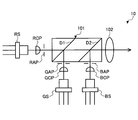
- Coupling lenses indicated by symbols RCP, GCP, and BCP suppress the divergence of each laser beam emitted from the semiconductor lasers RS, GS, and BS.
- a sealing member provided on the package 20a and a sealing plate provided on the lid are joined by seam welding in a nitrogen atmosphere or a vacuum environment.
- the optical deflector 20 of the present embodiment described above includes a mirror device including a swingable mirror 20d, and a container that houses the mirror device and has a window portion facing the mirror 20d.
- a transmission / reflection structure for example, a fine periodic pattern structure
- the window part and the mirror device can be arranged close to each other by making the window part and the mounting surface substantially parallel. Thereby, the enlargement of the optical deflector 20 can be suppressed, and consequently the enlargement of the image display device (projector 100) can be suppressed.
- the optical deflector 20 it is possible to suppress the light (stray light) reflected from the window portion of the incident light from reaching the scanned surface without causing an increase in size.
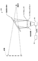
- the projector 100 is an image display device that displays an image by scanning a surface to be scanned with light.
- the projector 100 emits light based on image information data, and deflects light from the light source unit 10. Since the optical deflector 20 is provided, a high-contrast image can be displayed.
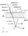
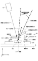
- FIG. 7 schematically shows the window portion of the optical deflector of the first modification.
- the reflected light from the window can be diffracted by applying a blazed diffraction grating to the window, but in order to improve productivity and obtain the same effect at a lower cost, a binary structure is used. It is effective to have a refractive index distribution equivalent to that of the blazed diffraction grating by the diffraction grating (binary diffraction grating).
- the diffraction angle and the binary structure period may be equal or different between the binary structure on the front surface and the binary structure on the back surface.
- the window portion is substantially parallel to the mounting surface on which the mirror device of the package is mounted.
- the design of the blazed diffraction grating can be made easier.
- the window portion is slightly inclined with respect to the mounting surface (for example, less than 15 °) for the purpose of reducing the distance between the mirror device and the window portion.
- the angle may be inclined by an angle, preferably less than 10 °, more preferably less than 5 °.
- the microlens array instead of the microlens array, other screen members such as a transmissive screen, a reflective screen, and a diffusion plate with fine irregularities formed on the surface may be used.
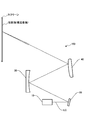
- an optical system including, for example, a concave mirror, a plane mirror, a convex mirror, or the like that guides light that forms an image from the screen member to the transmission / reflection member may be provided.
- the window reflection member for example, windshield
- the head-up display may not include the transmission / reflection member as a component.
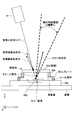
- the transmission / reflection structure is configured such that the optical path of the window portion incident light and the optical path of the window portion surface reflected light and the window portion rear surface incident light with respect to the optical path of the mirror reflected light when viewed from the ⁇ Y direction.
- the window surface reflected light and the window back surface reflected light may cross the deflection range of light by the mirror device.
- the transmissive reflection structure may be designed so that the optical paths of the window surface reflected light and the window back surface reflected light intersect the + X side end line of the deflection angle range.
- the transmission / reflection structure has the optical path of the window surface reflected light and the window rear surface reflected light on the ⁇ X side of the window incident light and the deflection range when viewed from the ⁇ Y direction.
- the optical path of the window portion surface reflected light and the window portion rear surface reflected light is located between the optical path of the window portion incident light and the deflection range, as in Modification 7 shown in FIG. May be designed to do.
Abstract
L'invention concerne un déflecteur de lumière (20) pourvu d'un dispositif de miroir comprenant un miroir oscillant (20d), et un corps de stockage qui stocke le dispositif de miroir et comporte une fenêtre qui fait face au miroir (20d). La fenêtre permet à une partie de la lumière incidente de passer à travers celle-ci et réfléchit au moins une partie de la lumière restante à l'extérieur de la plage de la déflexion de lumière créée par le dispositif de miroir. En tant que telle, la présente invention peut fournir un déflecteur de lumière susceptible de réduire au minimum la lumière qui atteint une surface de balayage après avoir été réfléchie à partir de la fenêtre sans augmentation de la taille du dispositif.
Priority Applications (3)
| Application Number | Priority Date | Filing Date | Title |
|---|---|---|---|
| JP2016563606A JP6439802B2 (ja) | 2014-12-08 | 2015-11-26 | 光偏向器、画像表示装置及び物体装置 |
| EP15867037.2A EP3232247B1 (fr) | 2014-12-08 | 2015-11-26 | Dispositif d'affichage d'image et dispositif objet |
| US15/612,259 US10459218B2 (en) | 2014-12-08 | 2017-06-02 | Optical deflector, image displaying apparatus, and object apparatus |
Applications Claiming Priority (2)
| Application Number | Priority Date | Filing Date | Title |
|---|---|---|---|
| JP2014-247545 | 2014-12-08 | ||
| JP2014247545 | 2014-12-08 |
Related Child Applications (1)
| Application Number | Title | Priority Date | Filing Date |
|---|---|---|---|
| US15/612,259 Continuation US10459218B2 (en) | 2014-12-08 | 2017-06-02 | Optical deflector, image displaying apparatus, and object apparatus |
Publications (1)
| Publication Number | Publication Date |
|---|---|
| WO2016093066A1 true WO2016093066A1 (fr) | 2016-06-16 |
Family
ID=56107256
Family Applications (1)
| Application Number | Title | Priority Date | Filing Date |
|---|---|---|---|
| PCT/JP2015/083183 WO2016093066A1 (fr) | 2014-12-08 | 2015-11-26 | Déflecteur de lumière, dispositif d'affichage d'image, et dispositif objet |
Country Status (4)
| Country | Link |
|---|---|
| US (1) | US10459218B2 (fr) |
| EP (1) | EP3232247B1 (fr) |
| JP (1) | JP6439802B2 (fr) |
| WO (1) | WO2016093066A1 (fr) |
Cited By (5)
| Publication number | Priority date | Publication date | Assignee | Title |
|---|---|---|---|---|
| EP3267237A1 (fr) * | 2016-07-06 | 2018-01-10 | Ricoh Company, Ltd. | Dispositif de balayage optique, dispositif de projection et afficheur |
| JP2018132741A (ja) * | 2017-02-17 | 2018-08-23 | スタンレー電気株式会社 | 電子部品用パッケージ及び電子部品用パッケージの製造方法 |
| JP2019086765A (ja) * | 2017-11-08 | 2019-06-06 | 三星電子株式会社Samsung Electronics Co.,Ltd. | メタレンズを含むプロジェクタ |
| WO2019194276A1 (fr) * | 2018-04-06 | 2019-10-10 | 株式会社小糸製作所 | Appareil d'éclairage pour véhicule, unité de modulation de lumière spatiale et unité d'appareil d'éclairage |
| US20210063726A1 (en) * | 2018-01-17 | 2021-03-04 | Robert Bosch Gmbh | Micromechanical light deflection device |
Families Citing this family (10)
| Publication number | Priority date | Publication date | Assignee | Title |
|---|---|---|---|---|
| JP2016065964A (ja) * | 2014-09-24 | 2016-04-28 | 株式会社デンソー | 光学部品 |
| US9928769B2 (en) * | 2015-09-29 | 2018-03-27 | Panasonic Intellectual Property Management Co., Ltd. | Head-up display and vehicle equipped with head-up display |
| JP7021999B2 (ja) * | 2018-04-06 | 2022-02-17 | 株式会社小糸製作所 | 車両用灯具 |
| JP7167500B2 (ja) | 2018-06-25 | 2022-11-09 | 株式会社リコー | 可動装置、画像投影装置、ヘッドアップディスプレイ、レーザヘッドランプ、ヘッドマウントディスプレイ、物体認識装置、及び車両 |
| WO2020138640A1 (fr) * | 2018-12-26 | 2020-07-02 | 엘지전자 주식회사 | Dispositif électronique |
| US11372238B2 (en) | 2019-01-30 | 2022-06-28 | Hamamatsu Photonics K.K. | Mirror unit |
| US11333882B2 (en) | 2019-01-30 | 2022-05-17 | Hamamatsu Photonics K.K. | Optical unit |
| DE102019204552A1 (de) * | 2019-04-01 | 2020-10-01 | Robert Bosch Gmbh | Optisches System |
| US11796793B2 (en) | 2019-11-27 | 2023-10-24 | Ricoh Company, Ltd. | Optical deflector, deflection apparatus, distance measuring apparatus, image projecting apparatus, and movable body |
| IT202000016855A1 (it) * | 2020-07-10 | 2022-01-10 | St Microelectronics Srl | Dispositivo a microspecchio mems chiuso in un involucro dotato di una superficie trasparente e avente una piattaforma orientabile |
Citations (6)
| Publication number | Priority date | Publication date | Assignee | Title |
|---|---|---|---|---|
| JP2005010341A (ja) * | 2003-06-18 | 2005-01-13 | Toppan Printing Co Ltd | ブレーズド型回折格子からなる光学シート |
| JP2007240880A (ja) * | 2006-03-08 | 2007-09-20 | Seiko Epson Corp | 光学デバイス |
| JP2009069457A (ja) * | 2007-09-13 | 2009-04-02 | Seiko Epson Corp | 光走査素子及び画像表示装置 |
| JP2011133530A (ja) * | 2009-12-22 | 2011-07-07 | Ricoh Co Ltd | 光偏向装置、光偏向アレー、画像投影表示装置 |
| JP2014063063A (ja) * | 2012-09-21 | 2014-04-10 | Nippon Seiki Co Ltd | 表示装置 |
| JP2014186136A (ja) * | 2013-03-22 | 2014-10-02 | Denso Corp | 鏡面を有する半導体装置 |
Family Cites Families (19)
| Publication number | Priority date | Publication date | Assignee | Title |
|---|---|---|---|---|
| DE69329945T2 (de) | 1992-07-14 | 2001-06-07 | Seiko Epson Corp | Polarisierendes element, optisches element und optischer kopf |
| JP2002071958A (ja) | 1992-07-14 | 2002-03-12 | Seiko Epson Corp | 偏光素子および光ヘッド |
| JP3427564B2 (ja) * | 1995-04-25 | 2003-07-22 | オムロン株式会社 | 光走査装置 |
| US7027469B2 (en) * | 2001-11-30 | 2006-04-11 | Optitune Plc | Tunable filter |
| KR100707179B1 (ko) * | 2005-02-07 | 2007-04-13 | 삼성전자주식회사 | 광스캐너 패키지 및 그 제조방법 |
| JP2006309852A (ja) | 2005-04-27 | 2006-11-09 | Toshiba Corp | 光ヘッド装置および情報記録再生装置 |
| DE602006015388D1 (de) * | 2005-05-09 | 2010-08-26 | Lg Electronics Inc | Optisches System eines tragbaren Projektors und mobiles Kommunikationsendgerät damit |
| JP2007072433A (ja) | 2005-08-11 | 2007-03-22 | Ricoh Co Ltd | 光集積素子及び光制御素子 |
| JP4520402B2 (ja) | 2005-12-07 | 2010-08-04 | 株式会社リコー | 複数波長光スイッチング素子・複数波長光スイッチングデバイス・カラー光スイッチング素子・カラー光スイッチングデバイス・複数波長光スイッチング素子アレイ・カラー光スイッチング素子アレイ・複数色画像表示装置およびカラー画像表示装置 |
| JP5195112B2 (ja) | 2008-07-18 | 2013-05-08 | 株式会社リコー | 屈折率センサ、屈折率センサアレイおよびバイオセンサ |
| JP2010230792A (ja) * | 2009-03-26 | 2010-10-14 | Seiko Epson Corp | 光学デバイス、光スキャナー及び画像形成装置 |
| JP2011112806A (ja) * | 2009-11-25 | 2011-06-09 | Panasonic Electric Works Co Ltd | Mems光スキャナおよびその製造方法 |
| JP5543810B2 (ja) | 2010-03-16 | 2014-07-09 | スタンレー電気株式会社 | 光偏向器パッケージ |
| US8864316B2 (en) * | 2010-04-28 | 2014-10-21 | Lemoptix Sa | Optical MEMS scanning micro-mirror with speckle reduction |
| JP5672529B2 (ja) | 2010-09-13 | 2015-02-18 | 株式会社リコー | 電気光学素子及びその製造方法、並びに、電気光学素子を用いた光偏向装置 |
| JP5772332B2 (ja) * | 2011-07-20 | 2015-09-02 | 富士通株式会社 | 巡回路決定についてのプログラム、方法及び装置 |
| JP2013155066A (ja) * | 2012-01-27 | 2013-08-15 | Asahi Glass Co Ltd | TiO2膜形成用組成物、TiO2膜付き物品、それらの製造方法およびTiO2膜 |
| JP4990420B1 (ja) * | 2012-04-04 | 2012-08-01 | 浜松ホトニクス株式会社 | 分光モジュールの製造方法 |
| JP5682692B2 (ja) | 2012-12-21 | 2015-03-11 | 株式会社リコー | 画像表示装置 |
-
2015
- 2015-11-26 WO PCT/JP2015/083183 patent/WO2016093066A1/fr active Application Filing
- 2015-11-26 JP JP2016563606A patent/JP6439802B2/ja active Active
- 2015-11-26 EP EP15867037.2A patent/EP3232247B1/fr active Active
-
2017
- 2017-06-02 US US15/612,259 patent/US10459218B2/en active Active
Patent Citations (6)
| Publication number | Priority date | Publication date | Assignee | Title |
|---|---|---|---|---|
| JP2005010341A (ja) * | 2003-06-18 | 2005-01-13 | Toppan Printing Co Ltd | ブレーズド型回折格子からなる光学シート |
| JP2007240880A (ja) * | 2006-03-08 | 2007-09-20 | Seiko Epson Corp | 光学デバイス |
| JP2009069457A (ja) * | 2007-09-13 | 2009-04-02 | Seiko Epson Corp | 光走査素子及び画像表示装置 |
| JP2011133530A (ja) * | 2009-12-22 | 2011-07-07 | Ricoh Co Ltd | 光偏向装置、光偏向アレー、画像投影表示装置 |
| JP2014063063A (ja) * | 2012-09-21 | 2014-04-10 | Nippon Seiki Co Ltd | 表示装置 |
| JP2014186136A (ja) * | 2013-03-22 | 2014-10-02 | Denso Corp | 鏡面を有する半導体装置 |
Non-Patent Citations (1)
| Title |
|---|
| See also references of EP3232247A4 * |
Cited By (8)
| Publication number | Priority date | Publication date | Assignee | Title |
|---|---|---|---|---|
| EP3267237A1 (fr) * | 2016-07-06 | 2018-01-10 | Ricoh Company, Ltd. | Dispositif de balayage optique, dispositif de projection et afficheur |
| US10587849B2 (en) | 2016-07-06 | 2020-03-10 | Ricoh Company, Ltd. | Optical scanning device, projection device, and display device |
| JP2018132741A (ja) * | 2017-02-17 | 2018-08-23 | スタンレー電気株式会社 | 電子部品用パッケージ及び電子部品用パッケージの製造方法 |
| JP2019086765A (ja) * | 2017-11-08 | 2019-06-06 | 三星電子株式会社Samsung Electronics Co.,Ltd. | メタレンズを含むプロジェクタ |
| JP7269712B2 (ja) | 2017-11-08 | 2023-05-09 | 三星電子株式会社 | メタレンズを含むプロジェクタ |
| US20210063726A1 (en) * | 2018-01-17 | 2021-03-04 | Robert Bosch Gmbh | Micromechanical light deflection device |
| WO2019194276A1 (fr) * | 2018-04-06 | 2019-10-10 | 株式会社小糸製作所 | Appareil d'éclairage pour véhicule, unité de modulation de lumière spatiale et unité d'appareil d'éclairage |
| US11543095B2 (en) | 2018-04-06 | 2023-01-03 | Koito Manufacturing Co., Ltd. | Vehicle lamp with particular attachment of spatial light modulator to heat sink |
Also Published As
| Publication number | Publication date |
|---|---|
| JP6439802B2 (ja) | 2018-12-19 |
| US20170269354A1 (en) | 2017-09-21 |
| EP3232247A1 (fr) | 2017-10-18 |
| EP3232247B1 (fr) | 2020-09-30 |
| JPWO2016093066A1 (ja) | 2017-10-12 |
| EP3232247A4 (fr) | 2017-11-22 |
| US10459218B2 (en) | 2019-10-29 |
Similar Documents
| Publication | Publication Date | Title |
|---|---|---|
| JP6439802B2 (ja) | 光偏向器、画像表示装置及び物体装置 | |
| CN107193130B (zh) | 显示装置和导光装置 | |
| KR101193524B1 (ko) | 광 주사 유닛, 이를 포함하는 화상 투영 장치, 차량 헤드업 디스플레이 장치 및 휴대 전화기 | |
| KR101643077B1 (ko) | 헤드업 디스플레이 장치 | |
| US8690341B2 (en) | Image projector and an illuminating unit suitable for use in an image projector | |
| US10698149B2 (en) | Display for two-dimensional and/or three-dimensional images | |
| JP6225550B2 (ja) | ヘッドアップディスプレイ装置 | |
| EP2672308A2 (fr) | Dispositif d'affichage d'images et dispositif d'affichage monté sur la tête | |
| JP6606998B2 (ja) | スクリーン、画像表示装置及び物体装置 | |
| EP2733516A1 (fr) | Appareil d'affichage d'images et visiocasque | |
| US20170276957A1 (en) | Optical element and display apparatus | |
| JP2018084725A (ja) | 表示装置 | |
| CN109425989B (zh) | 偏转装置、显示装置以及偏转装置的制造方法 | |
| WO2017188008A1 (fr) | Dispositif d'affichage | |
| US7009778B2 (en) | Imaging optical system, image display apparatus and imaging optical apparatus | |
| WO2011142210A1 (fr) | Système optique à balayage et projecteur muni de ce dernier | |
| US11640053B2 (en) | Movable device, image projection apparatus, heads-up display, laser headlamp, head-mounted display, object recognition device, and mobile object | |
| WO2016136060A1 (fr) | Système optique de projection, et dispositif de projection d'image comportant ce système | |
| US11567327B2 (en) | Display module and display device | |
| JP7456294B2 (ja) | 可動装置、偏向装置、距離測定装置、画像投影装置、及び車両 | |
| WO2022059229A1 (fr) | Dispositif d'affichage tête haute | |
| US20220326512A1 (en) | Movable apparatus | |
| KR20230021971A (ko) | 도광판 및 그를 이용한 디스플레이 장치 | |
| WO2017179655A1 (fr) | Écran de transmission et dispositif d'affichage à balayage laser | |
| KR20220030055A (ko) | 홀로그래픽 도광판 및 이를 포함하는 디스플레이 장치 |
Legal Events
| Date | Code | Title | Description |
|---|---|---|---|
| 121 | Ep: the epo has been informed by wipo that ep was designated in this application |
Ref document number: 15867037 Country of ref document: EP Kind code of ref document: A1 |
|
| ENP | Entry into the national phase |
Ref document number: 2016563606 Country of ref document: JP Kind code of ref document: A |
|
| REEP | Request for entry into the european phase |
Ref document number: 2015867037 Country of ref document: EP |
|
| NENP | Non-entry into the national phase |
Ref country code: DE |