WO2016092985A1 - 電力変換装置 - Google Patents
電力変換装置 Download PDFInfo
- Publication number
- WO2016092985A1 WO2016092985A1 PCT/JP2015/080871 JP2015080871W WO2016092985A1 WO 2016092985 A1 WO2016092985 A1 WO 2016092985A1 JP 2015080871 W JP2015080871 W JP 2015080871W WO 2016092985 A1 WO2016092985 A1 WO 2016092985A1
- Authority
- WO
- WIPO (PCT)
- Prior art keywords
- power
- power supply
- circuit
- voltage
- inverter
- Prior art date
- Legal status (The legal status is an assumption and is not a legal conclusion. Google has not performed a legal analysis and makes no representation as to the accuracy of the status listed.)
- Ceased
Links
Images


Classifications
-
- H—ELECTRICITY
- H02—GENERATION; CONVERSION OR DISTRIBUTION OF ELECTRIC POWER
- H02M—APPARATUS FOR CONVERSION BETWEEN AC AND AC, BETWEEN AC AND DC, OR BETWEEN DC AND DC, AND FOR USE WITH MAINS OR SIMILAR POWER SUPPLY SYSTEMS; CONVERSION OF DC OR AC INPUT POWER INTO SURGE OUTPUT POWER; CONTROL OR REGULATION THEREOF
- H02M7/00—Conversion of AC power input into DC power output; Conversion of DC power input into AC power output
- H02M7/42—Conversion of DC power input into AC power output without possibility of reversal
- H02M7/44—Conversion of DC power input into AC power output without possibility of reversal by static converters
- H02M7/48—Conversion of DC power input into AC power output without possibility of reversal by static converters using discharge tubes with control electrode or semiconductor devices with control electrode
Definitions
- the present invention relates to a power conversion device.
- a high voltage battery is used in an electric vehicle equipped with a power conversion device such as an inverter device.
- a switch such as a contactor is provided between the inverter device and the battery. When the inverter device is not in operation, the contactor is opened to electrically separate the battery and the inverter device to prevent electric shock when the vehicle is maintained.
- the inverter device is provided with a large-capacity capacitor to stabilize the voltage fluctuation during operation, and even if the contactor is opened, a high voltage that remains charged remains in the capacitor. The prevention of electric shock is not enough. For this reason, a device has been proposed in which a quick discharge circuit is usually provided inside the inverter device and the electric charge remaining in the capacitor is rapidly discharged (see Patent Document 1).
- Patent Document 1 it is necessary to provide a dedicated rapid discharge circuit, and for the discharge switch and discharge resistor used in the rapid discharge circuit, large-sized large parts are required, and the power converter is small. And cost reduction.
- the inverter circuit connected via the contactor that can open and close the first DC power supply, and the voltage smoothing connected in parallel with the first DC power supply on the input side of the inverter circuit
- the power supply circuit supplies power based on the input power from the first DC power supply.
- the contactor is open, the power supply circuit supplies power based on the input power from the capacitor.
- an inverter control unit that receives power supply from the power supply circuit or the second DC power supply and controls the inverter circuit, and when the contactor is opened, the power supply from the second DC power supply is changed, By receiving power supply from the power supply circuit and operating the inverter control unit, the capacitor charge is discharged.
- a capacitor can be discharged without adding a large component with a large rating, and a small and low-cost power conversion device can be provided.
- FIG. 1 is a diagram showing a control block of a hybrid vehicle.
- An electric power conversion device for an electric system mounted on an automobile particularly an inverter device used for an electric drive system for a vehicle, is placed in a severe ambient environment or an operating environment.
- the inverter device converts the DC power supplied from the in-vehicle battery or the in-vehicle power generation device into AC power, and supplies the AC power to the AC motor for driving the vehicle for driving, while the AC power generated by the AC motor for driving the vehicle is used. Inversely converted to DC power, the DC power is supplied to the in-vehicle battery and charged.
- a hybrid electric vehicle (hereinafter referred to as HEV) 110 is one electric vehicle and includes two vehicle driving systems.
- One of them is an engine system using an engine (ENG) 120 which is an internal combustion engine as a power source.
- This engine system is mainly used as a drive source for the HEV 110.
- the other one is an in-vehicle electric system using motor generators (MG1, MG2) 192, 194 as a power source.
- This in-vehicle electric system is mainly used as a drive source for HEV 110 and a power generation source for HEV 110.
- the motor generators 192 and 194 are, for example, synchronous machines or induction machines, and operate as both a motor and a generator depending on the operation method.
- a front wheel axle 114 is rotatably supported at the front portion of the vehicle body, and a pair of front wheels 112 are provided at both ends of the front wheel axle 114.
- a rear wheel axle (not shown) is rotatably supported at the rear portion of the vehicle body, and a pair of rear wheels (not shown) are provided at both ends of the rear wheel axle.
- the HEV 110 of this embodiment employs a so-called front wheel drive system in which a main wheel driven by power is a front wheel 112 and a driven wheel to be rotated is a rear wheel (not shown).
- the present invention can also be applied to a wheel drive type HEV.
- a front wheel side differential gear (hereinafter referred to as front wheel side DEF) 116 is provided at the center of the front wheel axle 114.
- the front wheel axle 114 is mechanically connected to the output side of the front wheel side DEF 116.
- the output shaft of the transmission 118 is mechanically connected to the input side of the front wheel side DEF 116.
- the front wheel side DEF 116 is a differential power distribution mechanism that distributes the rotational driving force that is shifted and transmitted by the transmission (T / M) 118 to the left and right front wheel axles 114.
- the output side of the motor generator 192 is mechanically connected to the input side of the transmission 118.
- the output side of the engine 120 and the output side of the motor generator 194 are mechanically connected to the input side of the motor generator 192 via the power distribution mechanism 122.
- Motor generators 192 and 194 and power distribution mechanism 122 are housed inside the casing of transmission 118.
- the motor generators 192 and 194 are synchronous machines having permanent magnets in the rotor, and the AC power supplied to the armature windings of the stator is controlled by the inverter devices (INV1, INV2) 140, 142, thereby the motors. Drive control of the generators 192 and 194 is performed.
- a battery (BAT) 136 is electrically connected to the inverter devices 140 and 142, and power is exchanged between the battery 136 and the inverter devices 140 and 142.
- the HEV 110 of this embodiment includes two sets of motor power generation units, a first motor power generation unit including a motor generator 192 and an inverter device 140, and a second motor power generation unit including a motor generator 194 and an inverter device 142. Use them properly according to the situation. That is, in the case where the vehicle is driven by the power from the engine 120, when assisting the driving torque of the vehicle, the second motor generator unit is operated as a power generation unit by the power of the engine 120, and is obtained by the power generation. The first motor generator unit is operated as an electric unit using electric power.
- the first motor generator unit is generated as a power generation unit by the power of the engine 120, and the second motor generator unit is electrically driven using the electric power obtained by the power generation. Operate as a unit.
- the first motor generator unit is operated as an electric unit using the electric power of the battery 136, and the vehicle can be driven only by the power of the motor generator 192. Furthermore, in the HEV 110 of this embodiment, the battery 136 can be charged by operating the first motor generator unit or the second motor generator unit as a generator unit by the power of the engine 120 or the power from the wheels.
- the battery 136 is also used as a power source for driving the auxiliary motor (M) 195.
- the auxiliary machine includes, for example, a motor for driving a compressor of an air conditioner or a motor for driving a hydraulic pump for control.
- DC power is supplied from the battery 136 to the inverter device (INV3) 43, and the inverter device 43 receives AC power. And is supplied to the motor 195.
- This auxiliary inverter device 43 has the same function as the vehicle drive inverter devices 140 and 142, and controls the phase, frequency and power of the alternating current supplied to the motor 195.
- the motor 195 generates torque by supplying AC power having a leading phase with respect to the rotation of the rotor of the motor 195.
- the motor 195 operates as a generator, and the motor 195 enters a regenerative braking operation.
- Such a control function of the inverter device 43 is the same as the control function of the inverter devices 140 and 142. Since the capacity of the motor 195 is smaller than the capacity of the motor generators 192 and 194, the maximum conversion power of the inverter device 43 is smaller than the inverter devices 140 and 142, but the circuit configuration of the inverter device 43 is basically the circuit of the inverter devices 140 and 142. Same as the configuration.
- the capacitor 500 is for voltage smoothing, and a small-capacitance capacitor is connected in parallel or in series to form a large-capacity capacitor module. In this specification, it is represented as a single capacitor. Capacitor 500 is in an electrical close relationship with inverter devices 140 and 142 and inverter device 43, and also has a common point that countermeasures against heat generation are necessary. In addition, it is desired to reduce the volume of the apparatus as much as possible. From these points, the power conversion device 700 described in detail below includes the inverter devices 140 and 142, the inverter device 43, and the capacitor 500 in the casing of the power conversion device 700. With such a configuration, a small and highly reliable device can be realized.
- the inverter devices 140 and 142, the inverter device 43, and the capacitor 500 in a single housing, it is effective in simplifying wiring and taking measures against noise. Furthermore, the inductance of the connection circuit between the capacitor 500 and the inverter devices 140 and 142 and the inverter device 43 can be reduced. This can suppress the generation of spike voltage, and can reduce heat generation and improve heat dissipation efficiency.
- the circuit configuration of the inverter device 140 will be described with reference to FIG.
- the inverter device 140 will be described as a representative example, but the same applies to the inverter device 142 and the inverter device 43.
- the inverter device 140 converts the DC voltage from the battery 136 into an AC voltage and drives the motor generator 192.
- the voltage smoothing capacitor 500 is connected in parallel with the battery 136.
- Contactor 15 connects and disconnects battery 136 and inverter device 140. When the contactor 15 is opened, the voltage smoothing capacitor 500 is also disconnected from the battery 136.
- the inverter device 140 includes an inverter circuit 12, a driver circuit board 17, a controller circuit board 18, and a backup power source 600.
- the driver circuit board 17 is provided with a driver circuit 21 for driving the inverter circuit 12 and a driver power supply 603 for supplying power to the driver circuit 21.
- the controller circuit board 18 is provided with a controller circuit 604 that controls the inverter device 140 and switches 605 and 606 that open and close the power supply circuit from the 12V power supply 19 in accordance with a command from the host controller 454.
- the switch 605 is a normally closed switch
- the switch 606 is a normally open type switch.
- a mechanical switch is illustrated, but a semiconductor switch using a transistor or a MOSFET can also be realized.
- the backup power source 600 is connected in parallel to the battery 136 and the voltage smoothing capacitor 500, and receives a secondary side DC voltage that is insulated and stepped down using the input voltage of the battery 136 or the capacitor 500 as a high voltage power source as a primary side input. Output.
- the backup power source 600 is constituted by an insulating switching power source using an insulating transformer, for example. As long as the backup power supply 600 is an insulated step-down power supply circuit, its method is not limited.
- the inverter circuit 12 is configured by a power semiconductor element having a three-phase bridge configuration, and upper and lower arm series circuits 123U, 123V, and 123W each including two power semiconductor elements are provided corresponding to the U phase, the V phase, and the W phase. Yes.
- the upper and lower arm series circuits 123U, 123V, and 123W are electrically connected to the positive electrode line P and the negative electrode line N, respectively.
- the battery 136 supplies a voltage to the inverter circuit 12 via the contactor 15 provided between the battery 136 and the capacitor 500. Opening and closing of the contactor 15 is controlled by a host controller 454 such as an engine controller or a battery controller. For example, in HEV, an opening / closing operation is performed by a contactor opening / closing signal from a host controller 454 linked with engine start and engine stop, and a contactor opening / closing signal from a host controller 454 linked with an interlock circuit 200 described later.
- a host controller 454 such as an engine controller or a battery controller.
- an opening / closing operation is performed by a contactor opening / closing signal from a host controller 454 linked with engine start and engine stop, and a contactor opening / closing signal from a host controller 454 linked with an interlock circuit 200 described later.
- Each power semiconductor element provided in the inverter circuit 12 is driven and controlled by the driver circuit 21.
- a driver circuit 21 for six phases for driving and controlling each power semiconductor element having a three-phase bridge configuration is provided on the driver circuit board 17.
- Each driver circuit 21 is supplied with insulated power by a driver power supply 603.
- the driver power supply 603 is supplied with a first route through which power is supplied from the 12V system power supply 19 and a second route for supplying the battery 136 which is a high voltage power supply with the backup power supply 600 insulated and stepped down. A route is provided.
- the controller circuit board 18 also has a first route from the 12V system power supply 19 and a second route from the backup power supply 600.
- the battery 136 is a battery having a voltage of 200V to 400V.
- the driver circuit 21 performs switching control of the power semiconductor element of the inverter circuit 12 based on the PWM signal M from the controller circuit 604. That is, when driving the lower arm, the driver circuit 21 insulates and amplifies the lower arm PWM signal and outputs it as a drive signal to the gate electrode of the power semiconductor element of the lower arm. Similarly, when the upper arm is driven, the upper arm PWM signal is insulated and amplified and output as a drive signal to the gate electrode of the power semiconductor element of the upper arm. Thereby, each power semiconductor element performs a switching operation based on the input drive signal. That is, when a portion that controls the inverter circuit 12 is referred to as an inverter control unit, the inverter control unit includes the driver circuit 21 and the controller circuit 604.
- the controller circuit 604 receives a command for driving the motor generator 192 such as a target torque value and a rotation command from the host controller 454.
- the controller circuit 604 also includes a current value supplied to the armature winding of the motor generator 192 detected by a current sensor (not shown) and a motor generator 192 detected by a resolver (not shown) provided in the motor generator 192.
- the magnetic pole position (rotation angle) is input.
- the controller circuit 604 includes a microcomputer 25 for calculating the switching timing of the power semiconductor element.
- the microcomputer 25 calculates d-axis and q-axis current command values of the motor generator 192 based on the target torque value, and d based on the calculated d-axis and q-axis current command values and the detection result of the current sensor. Based on the difference between the current value of the axis and the q axis, the voltage command value of the d axis and the q axis is calculated.
- the calculated d-axis and q-axis voltage command values are converted into U-phase, V-phase, and W-phase voltage command values based on the detected magnetic pole positions, and further, the U-phase, V-phase, and W-phase voltage command values are converted.
- a pulse-like modulated wave is generated, and the generated modulated wave is used as a PWM (pulse width modulation) signal M as the driver circuit 21. Output to.
- the secondary output voltage of the backup power supply 600 is connected to the power supply line of the 12V system power supply 19 via diodes 601 and 602, respectively.
- the secondary output voltage of the backup power supply 600 is set in advance lower than the output voltage of the 12V system power supply 19, and the diode 601 cuts off the output voltage of the 12V system power supply 19.
- power supply to the driver power supply 603 and the controller circuit 604 is normally performed from the 12V system power supply 19 and not from the backup power supply 600.
- the operating voltage of the backup power supply 600 can operate from 30 V to the maximum voltage of the battery 136 or from 30 V to the maximum induced voltage of the motor generator 192.
- the voltage detection circuit 24 detects the voltage of the positive line P with respect to the negative line N and outputs it to the microcomputer 25.
- the microcomputer 25 controls the opening and closing of the switches 605 and 606 according to the detected voltage, and generates the above-described PWM signal.
- the voltage detection circuit 24 and the microcomputer 25 are supplied with the output voltage of the 12V power supply 19 in a normal state where the switch 605 is closed.
- the voltage detection circuit 24 and the microcomputer 25 are the minimum necessary circuits for safely operating or stopping the inverter device 140. Even when the 12V power supply 19 is lost due to a failure or the like, power is supplied from the backup power supply 600, so that the inverter device 140 can be operated or stopped safely, and a highly reliable device can be realized.
- the control circuit 26 of the controller circuit 604 is a resolver control circuit that controls a resolver provided in the motor generator 192, and a transmission circuit that transmits signals to and from other devices via a communication line such as CAN (Controller Area ⁇ ⁇ Network).
- CAN Controller Area ⁇ ⁇ Network
- the interlock circuit 200 includes a power source 201, a switch 202, and a resistor 203. Normally, the switch 202 is closed, and a voltage applied to the resistor 203 is input to the microcomputer 25 as a sensor voltage. When the cover covering the inverter device 140 is opened due to vehicle repair or the like, the switch 202 is opened and the voltage applied to the resistor 203 becomes zero. When the microcomputer 25 detects a change in the voltage applied to the resistor 203, the microcomputer 25 notifies the host controller 454 that the lid has been opened.
- the backup power supply 600 is also used as a discharge function for discharging the charge charged in the capacitor 500. That is, the capacitor 500 is quickly discharged by the backup power source 600 or the like.
- the voltage at the start of discharge of the capacitor 500 is 400 V
- the time until the voltage 400 V is 42 V or less is considered as the discharge time.
- the voltage 42V is a voltage that requires only a slight electric shock even when touched by a person, and is used for various standards.
- the target of discharge time was set to within 5 seconds. The reason why the setting is within 5 seconds is that, for example, there is a time margin of 5 seconds or more after the contactor 15 is opened due to the engine stop or the like until the maintenance work of the inverter device 140 is started.
- the discharge time by the power consumption in the backup power supply 600 is determined by the capacitance of the capacitor 500, the voltage value applied to the backup power supply 600, and the power consumption. Normally, when power is supplied from the 12V system power supply 19 to the driver power supply 603 and the controller circuit 604, the load current of the secondary output voltage of the backup power supply 600 is almost zero, so the power consumption of the backup power supply 600 is about 1W. It is. With this power consumption, the capacitor 500 having a capacitance of 600 ⁇ F cannot be discharged from the voltage 400V to the voltage 42V within 5 seconds.
- switches 605 and 606 that can be controlled by the microcomputer 25 are provided, and by controlling the opening and closing thereof, the power consumption of the backup power supply 600 is intentionally increased when the capacitor 500 is discharged, and the discharge time is significantly shortened. is doing.
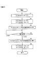
- the discharge operation in this embodiment will be described with reference to the flowchart of FIG.
- the host controller 454 opens the contactor 15 as shown in step S1, and the battery 136 and inverter The device 140 is disconnected.
- the backup power source 600 uses the battery 136 as a power source when the contactor 15 is closed.
- power supply based on the input power from the capacitor 500 is started.
- discharging of the capacitor 500 starts due to the power consumption of the backup power supply 600.
- step S2 the microcomputer 25 opens the switch 605 and cuts off the power supply from the 12V system power source 19 to the driver power source 603 and the controller circuit 604.
- the backup power supply 600 supplies power to the driver power supply 603, the voltage detection circuit 24 of the controller circuit 604, and the microcomputer 25.
- the microcomputer 25 closes the switch 606.
- the backup power supply 600 also supplies power to the control circuit 26 of the controller circuit 604.
- the driver circuit 21 and the controller circuit 604 can be operated by receiving power from the backup power supply 600. Therefore, the power consumption of the backup power supply 600 increases and the charge of the capacitor 500 can be discharged quickly.
- the power consumption P (P1 + P2) ⁇ K (2)
- V0 400V
- V1 42V
- C 600 ⁇ F
- P1 5W
- P2 12W
- K 0.85
- t ⁇ 2.4 seconds the target discharge time within 5 seconds can be realized.
- the discharge time is slightly longer than described above, but the switch 606 may remain open.
- step S3 the load factor of the microcomputer 25 is increased.
- a method of increasing the load factor for example, a method of moving all the cores of the multi-core, a method of speeding up the bus clock with a CPG (clock generator), a method of invalidating the cache and always accessing the bus, and enabling the cache
- CPG clock generator
- a method of invalidating the cache and always accessing the bus and enabling the cache
- enabling the cache A method of always purging is conceivable.
- Either method increases the load factor of the microcomputer 25 and increases the power consumption, which is effective in shortening the discharge time.
- step S4 the microcomputer 25 monitors the voltage of the capacitor 500 via the voltage detection circuit 24 and determines whether or not the voltage is lower than 42V. If the voltage of the capacitor 500 falls below 42V, the process proceeds to step S5, and if it is 42V or more, the process returns to step S4.
- step S5 the load factor of the microcomputer 25 is restored.
- step S6 the switch 605 is closed and the switch 606 is opened to switch to the power supply from the 12V system power supply 19 so that the power supply of the driver power supply 603 and the controller circuit 604 is not lost.
- the capacitor 500 can be rapidly discharged without adding a large component with a large rating, a small and low-cost inverter device can be provided.
- the power converter includes an inverter circuit 12 connected via a contactor 15 that can open and close a battery 136, a voltage smoothing capacitor 500 connected in parallel to the battery 136 on the input side of the inverter circuit 12, When the contactor 15 is closed, power is supplied based on the input power from the battery 136, and when the contactor 15 is open, the backup power supply 600 supplies power based on the input power from the capacitor 500; And an inverter control unit that receives power from the power source 600 or the 12V system power source 19 and controls the inverter circuit 12. When the contactor 15 is opened, the power source from the 12V system power source 19 is replaced with a backup power source. To operate the inverter control unit by receiving power supply from 600 Ri, discharges the electric charge of the capacitor 500. Therefore, the capacitor can be discharged without adding a large rated large component, and a small and low-cost power conversion device can be provided.
- the power converter includes a voltage detection circuit 24 that detects the voltage of the capacitor 500 when the contactor 15 is opened, and the voltage detection circuit 24 indicates that the voltage of the capacitor 500 has dropped below a predetermined voltage. When detected, the discharge by the inverter control unit is stopped. Therefore, the capacitor can be appropriately discharged.
- the inverter control unit includes a microcomputer 25 that executes arithmetic processing for controlling the inverter circuit 12, a resolver control circuit 26 that controls a resolver for detecting a rotation angle of a motor driven by the inverter circuit 12, At least one of the driver circuits 21 for driving the inverter circuit is included. Therefore, the capacitor can be discharged using a circuit that is normally used.
- the power conversion device increases the load factor of the microcomputer 25 and increases the power consumption. Therefore, the capacitor can be discharged rapidly.
- a first switch 605 for conducting or shutting off the power from the 12V system power supply 19 is further provided.
- the contactor 15 is opened, the first switch 605 is opened and the 12V system power supply 19 is connected to the inverter control unit. Shut off the power supply. Therefore, the discharge of the capacitor can be switched appropriately.
- the discharge circuit of the voltage smoothing capacitor is not limited to the motor drive inverter of the hybrid vehicle.
- the present invention can be applied not only to inverters used in general electric vehicles, but also to power converters such as inverters and DC-DC converters used in electric vehicles, ships, airplanes, and the like.
- the present invention can also be applied to all power converters widely used for general industries, or power converters for electric motors that drive household solar power generation systems and household appliances. Even when applied to these various power conversion devices, the same effects as those of the above-described embodiment can be obtained.
- the present invention is not limited to the above-described embodiment, and other forms conceivable within the scope of the technical idea of the present invention are also included in the scope of the present invention as long as the characteristics of the present invention are not impaired. .
Landscapes
- Engineering & Computer Science (AREA)
- Power Engineering (AREA)
- Inverter Devices (AREA)
- Electric Propulsion And Braking For Vehicles (AREA)
Abstract
本発明の目的は、大定格の大型部品を付加することなくキャパシタの放電を行うことができ、小型で低コストな電力変換装置を提供することである。急速放電回路を専用に設ける必要があり、急速放電回路には大定格の大型部品が要求され、電力変換装置の小型化、低コスト化を妨げていた。 本発明は、マイクロコンピュータ25は、コンタクタ15がオープンされると、スイッチ605をオープンし、12V系電源19からのドライバ電源603とコントローラ回路604への電力供給を遮断する。さらにマイクロコンピュータ25は、スイッチ606をクローズする。これによりバックアップ電源600はドライバ電源603とコントローラ回路604に電力を供給する。その結果、バックアップ電源600の消費電力が増大し、キャパシタ500の電荷を速やかに放電する。
Description
本発明は電力変換装置に関する。
インバータ装置などの電力変換装置が搭載される電気自動車では、高電圧のバッテリが使用される。インバータ装置とバッテリの間にはコンタクタなどの開閉器が設けられている。インバータ装置の非稼動時にはコンタクタを開路してバッテリとインバータ装置を電気的に分離して車両をメンテナンスする場合等の感電を防止している。
しかし、インバータ装置には稼動時の電圧変動を安定化させるため大容量のキャパシタが設けられており、コンタクタが開路されてもキャパシタには充電されたままの高電圧が残っており、コンタクタの開路だけでは感電防止は不十分である。そのため、通常はインバータ装置内部に急速放電回路を用意し、キャパシタに残っている電荷を急速に放電する装置が提案されている(特許文献1参照)。
しかしながら、特許文献1に記載の装置では急速放電回路を専用に設ける必要があり、さらに急速放電回路に用いられる放電用スイッチや放電抵抗は、大定格の大型部品が要求され、電力変換装置の小型化、低コスト化を妨げていた。
本発明の電力変換装置によれば、第1の直流電源が開閉可能なコンタクタを介して接続されるインバータ回路と、インバータ回路の入力側に第1の直流電源と並列に接続される電圧平滑用のキャパシタと、コンタクタが閉じているとき時には、第1の直流電源からの入力電力に基づいて電源を供給し、コンタクタが開いている時には、キャパシタからの入力電力に基づいて電源を供給する電源回路と、電源回路または第2の直流電源から電源の供給を受け、インバータ回路の制御を行うインバータ制御部とを備え、コンタクタが開かれた場合に、第2の直流電源からの電源に替えて、電源回路から電源の供給を受けてインバータ制御部を動作させることにより、キャパシタの電荷を放電する。
本発明によれば、大定格の大型部品を付加することなくキャパシタの放電を行うことができ、小型で低コストな電力変換装置を提供できる。
以下、図面を参照して本発明の一実施形態を説明する。
図1はハイブリッド自動車の制御ブロックを示す図である。自動車に搭載される電機システムの電力変換装置、特に車両駆動用電機システムに用いられるインバータ装置は、厳しい周囲環境や動作環境下に置かれる。インバータ装置は、車載バッテリまたは車載発電装置から供給される直流電力を交流電力に変換し、交流電力を車両駆動用交流電動機に供給して駆動する一方、車両駆動用交流電動機が発生する交流電力を直流電力に逆変換し、直流電力を車載バッテリに供給して充電する。
図1はハイブリッド自動車の制御ブロックを示す図である。自動車に搭載される電機システムの電力変換装置、特に車両駆動用電機システムに用いられるインバータ装置は、厳しい周囲環境や動作環境下に置かれる。インバータ装置は、車載バッテリまたは車載発電装置から供給される直流電力を交流電力に変換し、交流電力を車両駆動用交流電動機に供給して駆動する一方、車両駆動用交流電動機が発生する交流電力を直流電力に逆変換し、直流電力を車載バッテリに供給して充電する。
図1において、ハイブリッド電気自動車(以下、HEVと記述する)110は1つの電動車両であり、2つの車両駆動用システムを備えている。その1つは、内燃機関であるエンジン(ENG)120を動力源としたエンジンシステムである。このエンジンシステムは主としてHEV110の駆動源として用いられる。他の1つは、モータージェネレータ(MG1、MG2)192,194を動力源とした車載電機システムである。この車載電機システムは主としてHEV110の駆動源およびHEV110の電力発生源として用いられる。モータージェネレータ192,194は例えば同期機あるいは誘導機であり、運転方法によりモーターとしても発電機としても動作するので、以下ではモータージェネレータと呼ぶ。
車体のフロント部には前輪車軸114が回転可能に軸支されており、この前輪車軸114の両端には1対の前輪112が設けられている。一方、車体のリア部には後輪車軸(図示省略)が回転可能に軸支されており、この後輪車軸の両端には1対の後輪(不図示)が設けられている。この一実施形態のHEV110は、動力によって駆動される主輪を前輪112とし、連れ回される従輪を後輪(不図示)とする、いわゆる前輪駆動方式を採用しているが、この逆の後輪駆動方式のHEVに対しても本発明を適用することができる。
前輪車軸114の中央部には、前輪側デファレンシャルギア(以下、前輪側DEFと呼ぶ)116が設けられている。前輪車軸114は前輪側DEF116の出力側に機械的に接続されている。また、前輪側DEF116の入力側には変速機118の出力軸が機械的に接続されている。前輪側DEF116は、変速機(T/M)118により変速され伝達された回転駆動力を左右の前輪車軸114に分配する差動式動力分配機構である。変速機118の入力側にはモータージェネレータ192の出力側が機械的に接続されている。さらに、モータージェネレータ192の入力側には、動力分配機構122を介してエンジン120の出力側およびモータージェネレータ194の出力側が機械的に接続されている。なお、モータージェネレータ192,194および動力分配機構122は、変速機118の筐体の内部に収納されている。
モータージェネレータ192,194は回転子に永久磁石を備えた同期機であり、固定子の電機子巻線に供給される交流電力がインバータ装置(INV1、INV2)140,142によって制御され、これによりモータージェネレータ192,194の駆動制御が行われる。インバータ装置140,142にはバッテリ(BAT)136が電気的に接続されており、バッテリ136とインバータ装置140,142との間で電力の授受が行われる。
この一実施形態のHEV110は、モータージェネレータ192とインバータ装置140からなる第1電動発電ユニットと、モータージェネレータ194とインバータ装置142からなる第2電動発電ユニットとの2組の電動発電ユニットを備え、運転状態に応じてそれらを使い分ける。すなわち、エンジン120からの動力により車両を駆動している場合において、車両の駆動トルクをアシストする場合にはエンジン120の動力により第2電動発電ユニットを発電ユニットとして作動させ、その発電によって得られた電力を用いて第1電動発電ユニットを電動ユニットとして作動させる。また、同様の場合において、車両の車速をアシストする場合にはエンジン120の動力により第1電動発電ユニットを発電ユニットとして発電させ、その発電によって得られた電力を用いて第2電動発電ユニットを電動ユニットとして作動させる。
また、この一実施形態のHEV110では、バッテリ136の電力を用いて第1電動発電ユニットを電動ユニットとして作動させ、モータージェネレータ192の動力のみで車両を駆動することができる。さらに、この一実施形態のHEV110では、エンジン120の動力あるいは車輪からの動力により第1電動発電ユニットまたは第2電動発電ユニットを発電ユニットとして作動させ、バッテリ136を充電することができる。
バッテリ136は、さらに補機用モーター(M)195を駆動するための電源としても用いられる。補機には、例えばエアコンディショナーのコンプレッサーを駆動するモーター、あるいは制御用の油圧ポンプを駆動するモーターがあり、バッテリ136からインバータ装置(INV3)43に直流電力が供給され、インバータ装置43で交流電力に変換されてモーター195に供給される。この補機用のインバータ装置43は車両駆動用インバータ装置140や142と同様の機能を備え、モーター195に供給する交流の位相や周波数、電力を制御する。
例えば、モーター195の回転子の回転に対し進み位相の交流電力を供給することによって、モーター195がトルクを発生する。逆に、遅れ位相の交流電力を発生することによって、モーター195が発電機として動作し、モーター195は回生制動運転となる。このようなインバータ装置43の制御機能はインバータ装置140や142の制御機能と同様である。モーター195の容量がモータージェネレータ192や194の容量より小さいので、インバータ装置43の最大変換電力がインバータ装置140や142より小さいが、インバータ装置43の回路構成は基本的にインバータ装置140や142の回路構成と同じである。
キャパシタ500は電圧平滑用であり、小容量のキャパシタが並列もしくは直並列に接続されて大容量のキャパシタモジュールを形成しているが、この明細書では単一のキャパシタとして表す。キャパシタ500は、インバータ装置140や142およびインバータ装置43と電気的に密接な関係にあり、さらに発熱に対する対策が必要な点が共通している。また、装置の体積をできるだけ小さくすることが望まれている。これらの点から以下に詳述する電力変換装置700は、インバータ装置140、142およびインバータ装置43、さらにキャパシタ500を電力変換装置700の筐体内に内蔵している。このような構成によって小型で信頼性の高い装置を実現できる。
また、インバータ装置140、142およびインバータ装置43、さらにキャパシタ500を一つの筐体に内蔵することによって、配線の簡素化やノイズ対策において効果がある。さらに、キャパシタ500とインバータ装置140、142およびインバータ装置43との接続回路のインダクタンスを低減でき、これによりスパイク電圧の発生を抑制できる上に、発熱の低減や放熱効率の向上を図ることができる。
次に、図2を参照してインバータ装置140の回路構成について説明する。ここでは代表例としてインバータ装置140を例に説明するが、インバータ装置142、およびインバータ装置43も同様である。
インバータ装置140はバッテリ136からのDC電圧をAC電圧に変換してモータージェネレータ192を駆動する。電圧平滑用のキャパシタ500はバッテリ136と並列に接続される。コンタクタ15は、バッテリ136とインバータ装置140との接続および切り離しを行う。また、コンタクタ15が開かれると電圧平滑用のキャパシタ500もバッテリ136から切り離される。
インバータ装置140はインバータ回路12、ドライバ回路基板17、コントローラ回路基板18、バックアップ電源600を備えている。ドライバ回路基板17にはインバータ回路12を駆動するためのドライバ回路21とドライバ回路21に電力を供給するドライバ電源603が設けられている。
コントローラ回路基板18には上位コントローラ454からの指令に従い、インバータ装置140の制御を行うコントローラ回路604と12V系電源19からの電力供給回路を開閉するスイッチ605、606が設けられている。スイッチ605は常時閉、スイッチ606は常時開タイプの開閉器である。本実施形態では機械的な開閉器を図示しているが、トランジスタやMOSFETを使用した半導体スイッチでも実現可能である。
バックアップ電源600はバッテリ136および電圧平滑用のキャパシタ500に対して並列に接続され、高電圧電源であるバッテリ136またはキャパシタ500の入力電圧を一次側入力として絶縁かつ降圧された二次側直流電圧を出力する。バックアップ電源600は、例えば絶縁トランスを用いた絶縁型スイッチング電源で構成されている。バックアップ電源600は絶縁降圧型の電源回路であれば、その方式に制約は受けない。
インバータ回路12は3相ブリッジ構成のパワー半導体素子により構成されており各々2つのパワー半導体素子から成る上下アーム直列回路123U、123V、123WがU相、V相およびW相に対応して設けられている。上下アーム直列回路123U、123V、123Wは、それぞれ正極ラインPと負極ラインNに電気的に接続される。
バッテリ136は、キャパシタ500との間に設けられたコンタクタ15を介してインバータ回路12へ電圧を供給する。コンタクタ15の開閉は、エンジンコントローラ又はバッテリコントローラなどの上位コントローラ454により制御されている。例えばHEVではエンジン始動、エンジン停止と連携した上位コントローラ454からのコンタクタ開閉信号、後述するインターロック回路200と連携した上位コントローラ454からのコンタクタ開閉信号により開閉動作する。
インバータ回路12に設けられた各パワー半導体素子はドライバ回路21によって駆動制御される。ドライバ回路基板17上には、3相ブリッジ構成の各パワー半導体素子を駆動制御するための6相分のドライバ回路21が設けられている。各ドライバ回路21には絶縁された電源がドライバ電源603によって供給される。詳細は後述するが、ドライバ電源603には12V系電源19から電力が供給される第1のルートと、高電圧電源であるバッテリ136をバックアップ電源600にて絶縁かつ降圧して供給する第2のルートが設けられている。コントローラ回路基板18も同様に12V系電源19からの第1のルートとバックアップ電源600からの第2のルートを備えている。なお、電気自動車用の場合、バッテリ136は、電圧200V~400Vのバッテリが使用される。
ドライバ回路21は、コントローラ回路604からのPWM信号Mに基づいてインバータ回路12のパワー半導体素子のスイッチング制御を行う。すなわち、ドライバ回路21は下アームを駆動する場合、下アームPWM信号を絶縁かつ増幅し、これをドライブ信号として下アームのパワー半導体素子のゲート電極に出力する。同様に上アームを駆動する場合には上アームPWM信号を絶縁かつ増幅し、これをドライブ信号として上アームのパワー半導体素子のゲート電極に出力する。これにより、各パワー半導体素子は入力されたドライブ信号に基づいてスイッチング動作する。すなわち、インバータ回路12の制御を行う部分をインバータ制御部と称すると、このインバータ制御部は、ドライバ回路21およびコントローラ回路604により構成される。
コントローラ回路604には目標トルク値や回転指令などのモータージェネレータ192を駆動するための指令が上位コントローラ454から入力される。また、コントローラ回路604には、不図示の電流センサで検出されたモータージェネレータ192の電機子巻線に供給される電流値やモータージェネレータ192に設けられた不図示のレゾルバにより検出されたモータジェネレータ192の磁極位置(回転角)などが入力される。
コントローラ回路604は、パワー半導体素子のスイッチングタイミングを演算処理するためのマイクロコンピュータ25を備えている。マイクロコンピュータ25は、目標トルク値に基づいてモータージェネレータ192のd軸およびq軸の電流指令値を演算し、この演算されたd軸、q軸の電流指令値と電流センサの検出結果に基づくd軸、q軸の電流値との差分に基づいてd軸、q軸の電圧指令値を演算する。そして、演算されたd軸、q軸の電圧指令値を検出された磁極位置に基づいてU相、V相、W相の電圧指令値に変換し、さらに、U相、V相、W相の電圧指令値に基づく基本波(正弦波)と搬送波(三角波)との比較に基づいてパルス状の変調波を生成し、この生成された変調波をPWM(パルス幅変調)信号Mとしてドライバ回路21に出力する。
バックアップ電源600の二次側出力電圧は12V系電源19の電源ラインと、それぞれダイオード601、602を介して接続される。バックアップ電源600の二次側出力電圧はあらかじめ12V系電源19の出力電圧よりも低く設定され、ダイオード601は12V系電源19の出力電圧をカットオフしている。その結果、ドライバ電源603とコントローラ回路604への電力供給は通常12V系電源19から行われ、バックアップ電源600からは行われない。バックアップ電源600の動作電圧は30Vからバッテリ136の最大電圧まで、もしくは30Vからモータージェネレータ192の最大誘起電圧まで動作可能としている。
12V系電源19が故障等により喪失し、12V系電源19の出力電圧がバックアップ電源600の二次側出力電圧より低下すると、ダイオード602はカットオフしダイオード601が導通状態となる。このとき、ドライバ電源603とコントローラ回路604の電圧検出回路24及びマイクロコンピュータ25にバックアップ電源600から電力が供給される。
電圧検出回路24は、負極ラインNに対する正極ラインPの電圧を検出し、マイクロコンピュータ25へ出力する。マイクロコンピュータ25は、検出された電圧に応じてスイッチ605、606の開閉を制御すると共に、上述したPWM信号を生成する。電圧検出回路24及びマイクロコンピュータ25には、スイッチ605が閉じられた通常の状態では12V系電源19の出力電圧が供給される。電圧検出回路24及びマイクロコンピュータ25は、インバータ装置140を安全に動作または停止させる必要最低限の回路である。12V系電源19が故障等により喪失した場合にも、バックアップ電源600から電源が供給されるので、インバータ装置140を安全に動作または停止させることが可能となり信頼性の高い装置が実現できる。
コントローラ回路604の制御回路26は、モータージェネレータ192に設けられたレゾルバを制御するレゾルバ制御回路、CAN(Controller Area Network)などの通信回線を介して他の機器との間で信号を伝送する伝送回路、電流センサ駆動回路などを含み、スイッチ605が閉じられた通常の状態では12V系電源19の出力電圧が供給される。
インターロック回路200は、電源201、スイッチ202、抵抗203より構成され、通常はスイッチ202が閉じた状態であり抵抗203への印加電圧がセンサ電圧としてマイクロコンピュータ25へ入力されている。車両の修理等でインバータ装置140を覆う蓋が開かれるとスイッチ202が開となり、抵抗203への印加電圧が0となる。マイクロコンピュータ25はこの抵抗203への印加電圧の変化を検知すると蓋が開かれたことを上位コントローラ454へ通知する。
次に、バックアップ電源600における消費電力、および放電時間について説明する。本実施形態では、バックアップ電源600はキャパシタ500に充電された電荷を放電させる放電機能としても利用される。すなわち、バックアップ電源600等によりキャパシタ500の電荷を速やかに放電するように構成している。
一例として、キャパシタ500の放電開始時の電圧を400Vとし、その電圧400Vを42V以下とするまでの時間を放電時間として考える。電圧42Vは人が触れても軽度の感電で済む電圧とされ、さまざまな基準に使われているものである。そして、放電時間の目標を5秒以内と設定した。ここで5秒以内と設定した理由は、例えば、エンジン停止等によりコンタクタ15が開かれてから、インバータ装置140のメンテナンス作業を開始するまで5秒以上の時間的余裕があるからである。
バックアップ電源600における消費電力による放電時間は、キャパシタ500の静電容量、バックアップ電源600に印加される電圧値と消費電力により決まる。通常、12V系電源19からドライバ電源603およびコントローラ回路604に電源が供給されている時には、バックアップ電源600の二次側出力電圧の負荷電流はほぼゼロであるためバックアップ電源600の消費電力は1W程度である。この程度の消費電力では、静電容量600μFのキャパシタ500を電圧400Vから5秒以内に電圧42Vまで放電することはできない。そこで、本実施形態ではマイクロコンピュータ25で制御可能なスイッチ605、606を設け、その開閉をコントロールすることでキャパシタ500の放電時にバックアップ電源600の消費電力を意図的に増加させ放電時間を大幅に短縮している。
次に、本実施形態における放電動作について図3のフローチャートを参照して説明する。車両を停止してキーオフ操作がされると、若しくはインターロック回路200で蓋が開いたことが検知されると、ステップS1に示すように、上位コントローラ454はコンタクタ15をオープンし、バッテリ136とインバータ装置140とが切り離される。ここで、インバータ内部に電圧が残っていると、インバータ装置140を修理などする際に、高電圧に触れる危険性があるため、キャパシタ500に充電された電荷を速やかに放電させる必要がある。バックアップ電源600はコンタクタ15が閉じられている時にはバッテリ136を電源としているが、コンタクタ15がオープンになると、キャパシタ500からの入力電力に基づく電源供給を開始する。これにより、バックアップ電源600の電力消費によりキャパシタ500の電荷の放電が始まる。
次に、ステップS2に示すように、マイクロコンピュータ25は、スイッチ605をオープンし、12V系電源19からのドライバ電源603とコントローラ回路604への電力供給を遮断する。これによりバックアップ電源600は、ドライバ電源603とコントローラ回路604の電圧検出回路24およびマイクロコンピュータ25に電力を供給する。さらにマイクロコンピュータ25は、スイッチ606をクローズする。これにより、バックアップ電源600はコントローラ回路604の制御回路26にも電力を供給する。その結果、バックアップ電源600から電源の供給を受けてドライバ回路21およびコントローラ回路604を動作させることができる。したがって、バックアップ電源600の消費電力が増大しキャパシタ500の電荷を速やかに放電することが出来る。
放電開始時の充電電圧をV0、放電後電圧をV1、キャパシタ容量をC、バックアップ電源600の消費電力をPとした場合、放電時間tは以下の式(1)で求められる。
t=0.5×C×(V02-V12)÷P ・・・ (1)
t=0.5×C×(V02-V12)÷P ・・・ (1)
またドライバ電源603の消費電力をP1、コントローラ回路604の消費電力をP2、バックアップ電源600の効率をKとすると、消費電力Pは以下の式(2)で求められる。
P=(P1+P2)÷K ・・・ (2)
P=(P1+P2)÷K ・・・ (2)
一例として、本実施形態における実測値をもとに式(1)、(2)にて放電時間を計算すると、V0=400V、V1=42V、C=600μF、P1=5W、P2=12W、K=0.85となり、t≒2.4秒が得られ、目標とした放電時間である5秒以内を実現できる。なお、放電時間は上述より若干長くなるがスイッチ606はオープンのままでもよい。
次に、ステップS3で、マイクロコンピュータ25の負荷率を上げる。負荷率を上げる方法としては、例えば、マルチコアの全てのコアを動かす方法、CPG(クロック発生器)でバスクロックを速くする方法、キャッシュを無効化させて常にバスアクセスさせる方法、キャッシュを有効にして常にパージ処理させる方法等が考えられる。いずれの方法によってもマイクロコンピュータ25の負荷率が上がり消費電力が増加するので、放電時間の短縮に効果がある。
ステップS4では、マイクロコンピュータ25は、電圧検出回路24を介してキャパシタ500の電圧を監視し、42Vを下回ったか否かを判定する。キャパシタ500の電圧が42Vを下回った場合にはステップS5へ進み、42V以上であればステップS4へ戻る。
ステップS5では、マイクロコンピュータ25の負荷率を元に戻す。そして、ステップS6では、スイッチ605をクローズ、スイッチ606をオープンし、12V系電源19からの電源供給に切り替え、ドライバ電源603およびコントローラ回路604の電源が喪失しない構成としている。
本実施形態によれば、大定格の大型部品を付加することなくキャパシタ500の急速放電ができるため、小型で低コストなインバータ装置が提供可能である。
上述した実施形態によれば、次の作用効果が得られる。
(1)電力変換装置は、バッテリ136が開閉可能なコンタクタ15を介して接続されるインバータ回路12と、インバータ回路12の入力側にバッテリ136と並列に接続される電圧平滑用のキャパシタ500と、コンタクタ15が閉じているとき時には、バッテリ136からの入力電力に基づいて電源を供給し、コンタクタ15が開いている時には、キャパシタ500からの入力電力に基づいて電源を供給するバックアップ電源600と、バックアップ電源600または12V系電源19から電源の供給を受け、インバータ回路12の制御を行うインバータ制御部とを備え、コンタクタ15が開かれた場合に、12V系電源19からの電源に替えて、バックアップ電源600から電源の供給を受けてインバータ制御部を動作させることにより、キャパシタ500の電荷を放電する。したがって、大定格の大型部品を付加することなくキャパシタの放電を行うことができ、小型で低コストな電力変換装置を提供できる。
(1)電力変換装置は、バッテリ136が開閉可能なコンタクタ15を介して接続されるインバータ回路12と、インバータ回路12の入力側にバッテリ136と並列に接続される電圧平滑用のキャパシタ500と、コンタクタ15が閉じているとき時には、バッテリ136からの入力電力に基づいて電源を供給し、コンタクタ15が開いている時には、キャパシタ500からの入力電力に基づいて電源を供給するバックアップ電源600と、バックアップ電源600または12V系電源19から電源の供給を受け、インバータ回路12の制御を行うインバータ制御部とを備え、コンタクタ15が開かれた場合に、12V系電源19からの電源に替えて、バックアップ電源600から電源の供給を受けてインバータ制御部を動作させることにより、キャパシタ500の電荷を放電する。したがって、大定格の大型部品を付加することなくキャパシタの放電を行うことができ、小型で低コストな電力変換装置を提供できる。
(2)電力変換装置は、コンタクタ15が開かれた場合に、キャパシタ500の電圧を検出する電圧検出回路24を備え、電圧検出回路24が、キャパシタ500の電圧が所定電圧未満に低下したことを検出すると、インバータ制御部による放電を中止する。したがって、キャパシタの放電を適切に行うことができる。
(3)インバータ制御部は、インバータ回路12を制御するための演算処理を実行するマイクロコンピュータ25、インバータ回路12により駆動されるモータの回転角を検出するためのレゾルバを制御するレゾルバ制御回路26、インバータ回路を駆動するドライバ回路21のいずれか少なくとも1を含む。したがって、キャパシタの放電を通常使用されている回路を用いて行うことができる。
(4)電力変換装置は、ココンタクタ15が開かれた場合に、マイクロコンピュータ25の負荷率を上げて消費電力を増加させる動作を実行する。したがって、キャパシタの放電を急速に行うことができる。
(5)12V系電源19からの電源を導通または遮断する第1のスイッチ605をさらに備え、コンタクタ15が開かれた場合に、第1のスイッチ605を開いて12V系電源19からインバータ制御部への電源の供給を遮断する。したがって、キャパシタの放電を適切に切り替えることができる。
次のような変形も本発明の範囲内であり、変形例の一つ、もしくは複数を上述の実施形態と組み合わせることも可能である。
(変形例1)実施形態ではハイブリッド自動車のモーター駆動用インバータに適用した例で説明した。しかし、電圧平滑用のキャパシタの放電回路は、ハイブリッド自動車のモーター駆動用インバータに限定されない。例えば、一般的な電気自動車に用いられるインバータはもちろんのこと、電気車両、船舶、航空機などで用いられるインバータやDC-DCコンバータなどの電力変換装置に適用できる。また、広く一般産業用として用いられるすべての電力変換装置、あるいは家庭の太陽光発電システムや家庭の電化製品を駆動する電動機の電力変換装置にも適用することができる。これらの様々な電力変換装置に適用した場合にも、上述した実施形態と同様な効果を得ることができる。
本発明は、上述した実施形態に限定されるものではなく、本発明の特徴を損なわない限り、本発明の技術思想の範囲内で考えられるその他の形態についても、本発明の範囲内に含まれる。
12 インバータ回路
15 コンタクタ
136 バッテリ
600 バックアップ電源
700 電力変換装置
500 キャパシタ
140 インバータ装置
19 12V系電源
603 ドライバ電源
604 コントローラ回路
25 マイクロコンピュータ
15 コンタクタ
136 バッテリ
600 バックアップ電源
700 電力変換装置
500 キャパシタ
140 インバータ装置
19 12V系電源
603 ドライバ電源
604 コントローラ回路
25 マイクロコンピュータ
Claims (5)
- 第1の直流電源が開閉可能なコンタクタを介して接続されるインバータ回路と、
前記インバータ回路の入力側に前記第1の直流電源と並列に接続される電圧平滑用のキャパシタと、
前記コンタクタが閉じているとき時には、前記第1の直流電源からの入力電力に基づいて電源を供給し、前記コンタクタが開いている時には、前記キャパシタからの入力電力に基づいて電源を供給する電源回路と、
前記電源回路または第2の直流電源から電源の供給を受け、前記インバータ回路の制御を行うインバータ制御部とを備え、
前記コンタクタが開かれた場合に、前記第2の直流電源からの電源に替えて、前記電源回路から電源の供給を受けて前記インバータ制御部を動作させることにより、前記キャパシタの電荷を放電する電力変換装置。 - 請求項1に記載の電力変換装置において、
前記コンタクタが開かれた場合に、前記キャパシタの電圧を検出する電圧検出部を備え、
前記電圧検出部が、前記キャパシタの電圧が所定電圧未満に低下したことを検出すると、前記インバータ制御部による放電を中止する電力変換装置。 - 請求項1または請求項2に記載の電力変換装置において、
前記インバータ制御部は、前記インバータ回路を制御するための演算処理を実行するマイクロコンピュータ、前記インバータ回路により駆動されるモータの回転角を検出するためのレゾルバを制御するレゾルバ制御回路、前記インバータ回路を駆動するドライバ回路のいずれか少なくとも1つを含む電力変換装置。 - 請求項3に記載の電力変換装置において、
前記コンタクタが開かれた場合に、前記マイクロコンピュータの負荷率を上げて消費電力を増加させる動作を実行する電力変換装置。 - 請求項1または請求項2に記載の電力変換装置において、
前記第2の直流電源からの電源を導通または遮断する第1のスイッチをさらに備え、
前記コンタクタが開かれた場合に、前記第1のスイッチを開いて前記第2の直流電源から前記インバータ制御部への電源の供給を遮断する電力変換装置。
Priority Applications (1)
| Application Number | Priority Date | Filing Date | Title |
|---|---|---|---|
| JP2016563571A JP6306210B2 (ja) | 2014-12-09 | 2015-11-02 | 電力変換装置 |
Applications Claiming Priority (2)
| Application Number | Priority Date | Filing Date | Title |
|---|---|---|---|
| JP2014-249257 | 2014-12-09 | ||
| JP2014249257 | 2014-12-09 |
Publications (1)
| Publication Number | Publication Date |
|---|---|
| WO2016092985A1 true WO2016092985A1 (ja) | 2016-06-16 |
Family
ID=56107180
Family Applications (1)
| Application Number | Title | Priority Date | Filing Date |
|---|---|---|---|
| PCT/JP2015/080871 Ceased WO2016092985A1 (ja) | 2014-12-09 | 2015-11-02 | 電力変換装置 |
Country Status (2)
| Country | Link |
|---|---|
| JP (1) | JP6306210B2 (ja) |
| WO (1) | WO2016092985A1 (ja) |
Cited By (8)
| Publication number | Priority date | Publication date | Assignee | Title |
|---|---|---|---|---|
| JP2018098826A (ja) * | 2016-12-08 | 2018-06-21 | 三菱電機株式会社 | 車両用電源装置および車両用電源装置の制御方法 |
| JP2018200403A (ja) * | 2017-05-26 | 2018-12-20 | 京セラドキュメントソリューションズ株式会社 | 画像形成装置 |
| CN111656666A (zh) * | 2018-02-06 | 2020-09-11 | 日立汽车系统株式会社 | 电力转换装置 |
| JP2020198764A (ja) * | 2019-06-05 | 2020-12-10 | アイシン・エィ・ダブリュ株式会社 | 回転電機制御システム |
| JP2021036738A (ja) * | 2019-08-30 | 2021-03-04 | 日立オートモティブシステムズ株式会社 | 電力変換装置 |
| JP7109631B1 (ja) | 2021-07-09 | 2022-07-29 | 三菱電機株式会社 | 電力変換装置 |
| CN116345405A (zh) * | 2021-12-23 | 2023-06-27 | 株式会社丰田自动织机 | 电动压缩机 |
| JP2024070924A (ja) * | 2022-11-14 | 2024-05-24 | トヨタ自動車株式会社 | 車両駆動システム |
Citations (3)
| Publication number | Priority date | Publication date | Assignee | Title |
|---|---|---|---|---|
| JPH09233830A (ja) * | 1996-02-26 | 1997-09-05 | Toyota Motor Corp | インバータ装置 |
| JP2011234507A (ja) * | 2010-04-27 | 2011-11-17 | Hitachi Automotive Systems Ltd | 電力変換装置 |
| JP2015162973A (ja) * | 2014-02-27 | 2015-09-07 | 株式会社デンソー | モータ駆動装置 |
Family Cites Families (1)
| Publication number | Priority date | Publication date | Assignee | Title |
|---|---|---|---|---|
| WO2010131340A1 (ja) * | 2009-05-13 | 2010-11-18 | トヨタ自動車株式会社 | 車両の電力変換装置およびそれを搭載する車両 |
-
2015
- 2015-11-02 JP JP2016563571A patent/JP6306210B2/ja active Active
- 2015-11-02 WO PCT/JP2015/080871 patent/WO2016092985A1/ja not_active Ceased
Patent Citations (3)
| Publication number | Priority date | Publication date | Assignee | Title |
|---|---|---|---|---|
| JPH09233830A (ja) * | 1996-02-26 | 1997-09-05 | Toyota Motor Corp | インバータ装置 |
| JP2011234507A (ja) * | 2010-04-27 | 2011-11-17 | Hitachi Automotive Systems Ltd | 電力変換装置 |
| JP2015162973A (ja) * | 2014-02-27 | 2015-09-07 | 株式会社デンソー | モータ駆動装置 |
Cited By (16)
| Publication number | Priority date | Publication date | Assignee | Title |
|---|---|---|---|---|
| JP2018098826A (ja) * | 2016-12-08 | 2018-06-21 | 三菱電機株式会社 | 車両用電源装置および車両用電源装置の制御方法 |
| JP2018200403A (ja) * | 2017-05-26 | 2018-12-20 | 京セラドキュメントソリューションズ株式会社 | 画像形成装置 |
| CN111656666A (zh) * | 2018-02-06 | 2020-09-11 | 日立汽车系统株式会社 | 电力转换装置 |
| CN111656666B (zh) * | 2018-02-06 | 2023-09-05 | 日立安斯泰莫株式会社 | 电力转换装置 |
| JP7259563B2 (ja) | 2019-06-05 | 2023-04-18 | 株式会社アイシン | 回転電機制御システム |
| JP2020198764A (ja) * | 2019-06-05 | 2020-12-10 | アイシン・エィ・ダブリュ株式会社 | 回転電機制御システム |
| JP2021036738A (ja) * | 2019-08-30 | 2021-03-04 | 日立オートモティブシステムズ株式会社 | 電力変換装置 |
| JP7377650B2 (ja) | 2019-08-30 | 2023-11-10 | 日立Astemo株式会社 | 電力変換装置 |
| CN115664241A (zh) * | 2021-07-09 | 2023-01-31 | 三菱电机株式会社 | 功率转换装置 |
| JP2023010126A (ja) * | 2021-07-09 | 2023-01-20 | 三菱電機株式会社 | 電力変換装置 |
| JP7109631B1 (ja) | 2021-07-09 | 2022-07-29 | 三菱電機株式会社 | 電力変換装置 |
| CN116345405A (zh) * | 2021-12-23 | 2023-06-27 | 株式会社丰田自动织机 | 电动压缩机 |
| US12280635B2 (en) * | 2021-12-23 | 2025-04-22 | Kabushiki Kaisha Toyota Jidoshokki | Electric compressor |
| CN116345405B (zh) * | 2021-12-23 | 2026-07-07 | 株式会社丰田自动织机 | 电动压缩机 |
| JP2024070924A (ja) * | 2022-11-14 | 2024-05-24 | トヨタ自動車株式会社 | 車両駆動システム |
| JP7845146B2 (ja) | 2022-11-14 | 2026-04-14 | トヨタ自動車株式会社 | 車両駆動システム |
Also Published As
| Publication number | Publication date |
|---|---|
| JP6306210B2 (ja) | 2018-04-04 |
| JPWO2016092985A1 (ja) | 2017-08-31 |
Similar Documents
| Publication | Publication Date | Title |
|---|---|---|
| JP6306210B2 (ja) | 電力変換装置 | |
| JP5567381B2 (ja) | 電力変換装置 | |
| CN103427762B (zh) | 电动机的驱动控制装置 | |
| US7723938B2 (en) | Control system for multiphase rotary electric machine | |
| CN103718453B (zh) | 电动机驱动系统 | |
| US9496810B2 (en) | Method and apparatus for controlling an electric machine | |
| US9667169B2 (en) | Power conversion apparatus | |
| KR101831468B1 (ko) | 삼상 이상의 전기 기기를 포함하는 차량 내 구동 어셈블리의 작동 방법 및 인버터용 제어 장치 | |
| JP2005020952A (ja) | 車両の制御装置 | |
| US9680405B2 (en) | Onboard motor controller | |
| US12491774B2 (en) | Motor control device, electromechanical integrated unit, boost converter system, electric vehicle system, and motor control method | |
| JP2009232652A (ja) | 回転電機制御システム及び当該回転電機制御システムを備えた車両駆動システム | |
| WO2008001949A1 (fr) | Dispositif d'entraînement de moteur | |
| JP2013132197A (ja) | 電力変換装置及び充電システム | |
| CN104024029A (zh) | 电动车控制装置以及电动车 | |
| CN112693314A (zh) | 车辆的电源系统 | |
| JP7032249B2 (ja) | 電源システム | |
| US20190248248A1 (en) | Controller of electrically powered vehicle | |
| JP2025008108A (ja) | 車載充電装置 | |
| JP2014093883A (ja) | 動力出力装置 | |
| JP5755583B2 (ja) | 電力制御システム | |
| JP4986639B2 (ja) | モータ制御装置 | |
| JP7499130B2 (ja) | 車両の電源システム | |
| JP7148463B2 (ja) | 制御装置、電動車両 | |
| JP2012235591A (ja) | 車両 |
Legal Events
| Date | Code | Title | Description |
|---|---|---|---|
| 121 | Ep: the epo has been informed by wipo that ep was designated in this application |
Ref document number: 15866756 Country of ref document: EP Kind code of ref document: A1 |
|
| ENP | Entry into the national phase |
Ref document number: 2016563571 Country of ref document: JP Kind code of ref document: A |
|
| NENP | Non-entry into the national phase |
Ref country code: DE |
|
| 122 | Ep: pct application non-entry in european phase |
Ref document number: 15866756 Country of ref document: EP Kind code of ref document: A1 |