WO2016092958A1 - 照明装置及び照明装置の制御方法並びに画像取得システム - Google Patents
照明装置及び照明装置の制御方法並びに画像取得システム Download PDFInfo
- Publication number
- WO2016092958A1 WO2016092958A1 PCT/JP2015/079732 JP2015079732W WO2016092958A1 WO 2016092958 A1 WO2016092958 A1 WO 2016092958A1 JP 2015079732 W JP2015079732 W JP 2015079732W WO 2016092958 A1 WO2016092958 A1 WO 2016092958A1
- Authority
- WO
- WIPO (PCT)
- Prior art keywords
- light
- light source
- emitted
- luminance
- white
- Prior art date
Links
- 238000005286 illumination Methods 0.000 title claims abstract description 231
- 238000000034 method Methods 0.000 title claims abstract description 80
- 235000019557 luminance Nutrition 0.000 claims description 228
- 230000003287 optical effect Effects 0.000 claims description 38
- 230000006866 deterioration Effects 0.000 claims description 20
- 238000004364 calculation method Methods 0.000 claims description 8
- 230000008859 change Effects 0.000 claims description 5
- 238000012545 processing Methods 0.000 description 79
- 238000003384 imaging method Methods 0.000 description 51
- 230000008569 process Effects 0.000 description 48
- 239000000523 sample Substances 0.000 description 32
- 230000007423 decrease Effects 0.000 description 19
- 239000003086 colorant Substances 0.000 description 17
- 238000010586 diagram Methods 0.000 description 17
- 238000001514 detection method Methods 0.000 description 9
- 238000006243 chemical reaction Methods 0.000 description 8
- 239000013078 crystal Substances 0.000 description 8
- 230000000694 effects Effects 0.000 description 8
- 239000004065 semiconductor Substances 0.000 description 7
- 230000005284 excitation Effects 0.000 description 6
- 238000012544 monitoring process Methods 0.000 description 6
- 238000005516 engineering process Methods 0.000 description 5
- 229910052736 halogen Inorganic materials 0.000 description 4
- 150000002367 halogens Chemical class 0.000 description 4
- 229910052724 xenon Inorganic materials 0.000 description 4
- FHNFHKCVQCLJFQ-UHFFFAOYSA-N xenon atom Chemical compound [Xe] FHNFHKCVQCLJFQ-UHFFFAOYSA-N 0.000 description 4
- 230000008878 coupling Effects 0.000 description 2
- 238000010168 coupling process Methods 0.000 description 2
- 238000005859 coupling reaction Methods 0.000 description 2
- 238000005259 measurement Methods 0.000 description 2
- 230000001151 other effect Effects 0.000 description 2
- 238000003825 pressing Methods 0.000 description 2
- 230000035945 sensitivity Effects 0.000 description 2
- 230000003595 spectral effect Effects 0.000 description 2
- 229910000980 Aluminium gallium arsenide Inorganic materials 0.000 description 1
- OAICVXFJPJFONN-UHFFFAOYSA-N Phosphorus Chemical compound [P] OAICVXFJPJFONN-UHFFFAOYSA-N 0.000 description 1
- 230000005540 biological transmission Effects 0.000 description 1
- 230000001427 coherent effect Effects 0.000 description 1
- 230000000295 complement effect Effects 0.000 description 1
- 230000003247 decreasing effect Effects 0.000 description 1
- 238000009792 diffusion process Methods 0.000 description 1
- 230000006872 improvement Effects 0.000 description 1
- 230000001678 irradiating effect Effects 0.000 description 1
- 230000001788 irregular Effects 0.000 description 1
- 229910044991 metal oxide Inorganic materials 0.000 description 1
- 150000004706 metal oxides Chemical class 0.000 description 1
- 238000012986 modification Methods 0.000 description 1
- 230000004048 modification Effects 0.000 description 1
- 239000007787 solid Substances 0.000 description 1
Images


Classifications
-
- H—ELECTRICITY
- H04—ELECTRIC COMMUNICATION TECHNIQUE
- H04N—PICTORIAL COMMUNICATION, e.g. TELEVISION
- H04N9/00—Details of colour television systems
- H04N9/64—Circuits for processing colour signals
- H04N9/73—Colour balance circuits, e.g. white balance circuits or colour temperature control
-
- A—HUMAN NECESSITIES
- A61—MEDICAL OR VETERINARY SCIENCE; HYGIENE
- A61B—DIAGNOSIS; SURGERY; IDENTIFICATION
- A61B1/00—Instruments for performing medical examinations of the interior of cavities or tubes of the body by visual or photographical inspection, e.g. endoscopes; Illuminating arrangements therefor
- A61B1/00002—Operational features of endoscopes
- A61B1/00057—Operational features of endoscopes provided with means for testing or calibration
-
- A—HUMAN NECESSITIES
- A61—MEDICAL OR VETERINARY SCIENCE; HYGIENE
- A61B—DIAGNOSIS; SURGERY; IDENTIFICATION
- A61B1/00—Instruments for performing medical examinations of the interior of cavities or tubes of the body by visual or photographical inspection, e.g. endoscopes; Illuminating arrangements therefor
- A61B1/06—Instruments for performing medical examinations of the interior of cavities or tubes of the body by visual or photographical inspection, e.g. endoscopes; Illuminating arrangements therefor with illuminating arrangements
- A61B1/0638—Instruments for performing medical examinations of the interior of cavities or tubes of the body by visual or photographical inspection, e.g. endoscopes; Illuminating arrangements therefor with illuminating arrangements providing two or more wavelengths
-
- A—HUMAN NECESSITIES
- A61—MEDICAL OR VETERINARY SCIENCE; HYGIENE
- A61B—DIAGNOSIS; SURGERY; IDENTIFICATION
- A61B1/00—Instruments for performing medical examinations of the interior of cavities or tubes of the body by visual or photographical inspection, e.g. endoscopes; Illuminating arrangements therefor
- A61B1/06—Instruments for performing medical examinations of the interior of cavities or tubes of the body by visual or photographical inspection, e.g. endoscopes; Illuminating arrangements therefor with illuminating arrangements
- A61B1/0655—Control therefor
-
- A—HUMAN NECESSITIES
- A61—MEDICAL OR VETERINARY SCIENCE; HYGIENE
- A61B—DIAGNOSIS; SURGERY; IDENTIFICATION
- A61B1/00—Instruments for performing medical examinations of the interior of cavities or tubes of the body by visual or photographical inspection, e.g. endoscopes; Illuminating arrangements therefor
- A61B1/06—Instruments for performing medical examinations of the interior of cavities or tubes of the body by visual or photographical inspection, e.g. endoscopes; Illuminating arrangements therefor with illuminating arrangements
- A61B1/0661—Endoscope light sources
- A61B1/0669—Endoscope light sources at proximal end of an endoscope
-
- A—HUMAN NECESSITIES
- A61—MEDICAL OR VETERINARY SCIENCE; HYGIENE
- A61B—DIAGNOSIS; SURGERY; IDENTIFICATION
- A61B1/00—Instruments for performing medical examinations of the interior of cavities or tubes of the body by visual or photographical inspection, e.g. endoscopes; Illuminating arrangements therefor
- A61B1/06—Instruments for performing medical examinations of the interior of cavities or tubes of the body by visual or photographical inspection, e.g. endoscopes; Illuminating arrangements therefor with illuminating arrangements
- A61B1/0661—Endoscope light sources
- A61B1/0684—Endoscope light sources using light emitting diodes [LED]
-
- G—PHYSICS
- G02—OPTICS
- G02B—OPTICAL ELEMENTS, SYSTEMS OR APPARATUS
- G02B23/00—Telescopes, e.g. binoculars; Periscopes; Instruments for viewing the inside of hollow bodies; Viewfinders; Optical aiming or sighting devices
- G02B23/24—Instruments or systems for viewing the inside of hollow bodies, e.g. fibrescopes
- G02B23/2407—Optical details
- G02B23/2461—Illumination
-
- H—ELECTRICITY
- H04—ELECTRIC COMMUNICATION TECHNIQUE
- H04N—PICTORIAL COMMUNICATION, e.g. TELEVISION
- H04N23/00—Cameras or camera modules comprising electronic image sensors; Control thereof
- H04N23/56—Cameras or camera modules comprising electronic image sensors; Control thereof provided with illuminating means
-
- H—ELECTRICITY
- H04—ELECTRIC COMMUNICATION TECHNIQUE
- H04N—PICTORIAL COMMUNICATION, e.g. TELEVISION
- H04N23/00—Cameras or camera modules comprising electronic image sensors; Control thereof
- H04N23/80—Camera processing pipelines; Components thereof
- H04N23/84—Camera processing pipelines; Components thereof for processing colour signals
- H04N23/88—Camera processing pipelines; Components thereof for processing colour signals for colour balance, e.g. white-balance circuits or colour temperature control
-
- H—ELECTRICITY
- H05—ELECTRIC TECHNIQUES NOT OTHERWISE PROVIDED FOR
- H05B—ELECTRIC HEATING; ELECTRIC LIGHT SOURCES NOT OTHERWISE PROVIDED FOR; CIRCUIT ARRANGEMENTS FOR ELECTRIC LIGHT SOURCES, IN GENERAL
- H05B47/00—Circuit arrangements for operating light sources in general, i.e. where the type of light source is not relevant
- H05B47/10—Controlling the light source
-
- A—HUMAN NECESSITIES
- A61—MEDICAL OR VETERINARY SCIENCE; HYGIENE
- A61B—DIAGNOSIS; SURGERY; IDENTIFICATION
- A61B1/00—Instruments for performing medical examinations of the interior of cavities or tubes of the body by visual or photographical inspection, e.g. endoscopes; Illuminating arrangements therefor
- A61B1/00163—Optical arrangements
- A61B1/00165—Optical arrangements with light-conductive means, e.g. fibre optics
-
- A—HUMAN NECESSITIES
- A61—MEDICAL OR VETERINARY SCIENCE; HYGIENE
- A61B—DIAGNOSIS; SURGERY; IDENTIFICATION
- A61B1/00—Instruments for performing medical examinations of the interior of cavities or tubes of the body by visual or photographical inspection, e.g. endoscopes; Illuminating arrangements therefor
- A61B1/06—Instruments for performing medical examinations of the interior of cavities or tubes of the body by visual or photographical inspection, e.g. endoscopes; Illuminating arrangements therefor with illuminating arrangements
- A61B1/063—Instruments for performing medical examinations of the interior of cavities or tubes of the body by visual or photographical inspection, e.g. endoscopes; Illuminating arrangements therefor with illuminating arrangements for monochromatic or narrow-band illumination
-
- F—MECHANICAL ENGINEERING; LIGHTING; HEATING; WEAPONS; BLASTING
- F21—LIGHTING
- F21V—FUNCTIONAL FEATURES OR DETAILS OF LIGHTING DEVICES OR SYSTEMS THEREOF; STRUCTURAL COMBINATIONS OF LIGHTING DEVICES WITH OTHER ARTICLES, NOT OTHERWISE PROVIDED FOR
- F21V23/00—Arrangement of electric circuit elements in or on lighting devices
- F21V23/003—Arrangement of electric circuit elements in or on lighting devices the elements being electronics drivers or controllers for operating the light source, e.g. for a LED array
-
- G—PHYSICS
- G01—MEASURING; TESTING
- G01N—INVESTIGATING OR ANALYSING MATERIALS BY DETERMINING THEIR CHEMICAL OR PHYSICAL PROPERTIES
- G01N21/00—Investigating or analysing materials by the use of optical means, i.e. using sub-millimetre waves, infrared, visible or ultraviolet light
- G01N21/17—Systems in which incident light is modified in accordance with the properties of the material investigated
- G01N21/25—Colour; Spectral properties, i.e. comparison of effect of material on the light at two or more different wavelengths or wavelength bands
-
- H—ELECTRICITY
- H05—ELECTRIC TECHNIQUES NOT OTHERWISE PROVIDED FOR
- H05B—ELECTRIC HEATING; ELECTRIC LIGHT SOURCES NOT OTHERWISE PROVIDED FOR; CIRCUIT ARRANGEMENTS FOR ELECTRIC LIGHT SOURCES, IN GENERAL
- H05B47/00—Circuit arrangements for operating light sources in general, i.e. where the type of light source is not relevant
- H05B47/10—Controlling the light source
- H05B47/105—Controlling the light source in response to determined parameters
- H05B47/11—Controlling the light source in response to determined parameters by determining the brightness or colour temperature of ambient light
Definitions
- the present disclosure relates to a lighting device, a lighting device control method, and an image acquisition system.
- Patent Document 1 discloses a light source device having a visible light LED having RGB independent light sources as an imaging system that can be used in an endoscope system, an electron microscope system, or the like.
- the desired color temperature, light quantity, etc. of the illumination light vary depending on the imaging object, the imaging purpose, and the user's preference. Therefore, in such a lighting device, further improvement in the degree of freedom in adjusting the color temperature and the light amount is desired.
- the illumination light is obtained by combining the white light emitted from the white light source and the emitted light from the RGB light source while adjusting the amount of the emitted light of each RGB color emitted from the RGB light source at least. Therefore, a novel and improved lighting device, a lighting device control method, and an image acquisition system capable of improving the degree of freedom of adjustment of color temperature and light amount are proposed.
- a white light source that emits white light
- an RGB light source that can independently adjust the amount of each emitted light
- a combined light that combines the white light and the emitted light into illumination light
- an illuminating device including a unit and a control unit that controls the amount of each emitted light.
- an illumination device that controls the amount of each emitted light emitted from the RGB light source, which is combined with the white light emitted from the white light source, to obtain illumination light having a desired luminance.
- a control method is provided.
- a white light source that emits white light
- an RGB light source that can independently adjust the amount of each emitted light
- the white light and the emitted light are combined to form illumination light.
- An image acquisition system includes a multiplexing unit, a light receiving unit that receives the illumination light, and a control unit that controls the amount of each emitted light.
- the white light emitted from the white light source and the emitted light from the RGB light source are combined while adjusting the light quantity of the emitted light of each RGB color emitted from the RGB light source.
- illumination light it is possible to improve the degree of freedom in adjusting the color temperature and the light amount.
- FIG. 5 is a flowchart illustrating an example of color temperature adjustment processing. It is a flowchart which shows an example of a light quantity adjustment process. It is a flowchart which shows an example of a multiplexing ratio adjustment process. It is a flowchart which shows an example of the deterioration determination process of a light source. It is a block diagram showing an image acquisition system concerning a 5th embodiment of this indication.
- First Embodiment (Example of controlling the amount of emitted light of each color of RGB)> [1.1. Example of overall configuration of image acquisition system] (1.1.1. Configuration example of lighting device) (1.1.2. Configuration example of imaging processing apparatus) [1.2. Illumination device control processing example] ⁇ 2. Second embodiment (example having a common control unit)> ⁇ 3. Third Embodiment (Example of controlling the amount of light emitted from white light and RGB colors)> [3.1. Example of overall configuration of image acquisition system] [3.2. Illumination device control processing example] (3.2.1 White balance adjustment processing example) (3.2.2. Color temperature adjustment processing example) (3.2.3. Light amount adjustment processing example) (3.2.4. Example of combining ratio adjustment process) ⁇ 4. Fourth Embodiment (an example having a light source deterioration determination processing function)> ⁇ 5. Fifth Embodiment (Example Using Color Sensor)>
- white light refers to light emitted from a white light source
- emitted light refers to light emitted from RGB light sources
- illumination light is emitted from an illumination device. It shall refer to light.
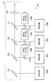
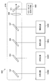
- FIG. 1 is a block diagram showing an overall configuration of an image acquisition system 10 according to the present embodiment.
- the image acquisition system 10 includes an illumination device 100 and an imaging processing device 200, and is configured as an endoscope system, for example.
- the endoscope system is an example of the image acquisition system 10 and may be another system such as an electron microscope system.
- the white light source 130W includes, for example, a blue LED (Light Emitting Diode) and a phosphor that emits yellow light when excited by the light emitted from the blue LED. Unlike the lamp light source such as a xenon lamp or a halogen lamp, the white light source 130W can electrically adjust the amount of emitted white light. However, the white light source 130W is not limited to the above example, and may be any light source that can emit white light.
- the red light source 130R is made of a semiconductor laser such as a GaInP quantum well structure laser diode
- the blue light source 130B is made of a semiconductor laser such as a GaInN quantum well structure laser diode.
- the green light source 130G is made of, for example, a solid-state laser that is excited by a semiconductor laser.
- the RGB light source is a three-color light source controlled by a semiconductor laser, and unlike a lamp light source such as a xenon lamp or a halogen lamp, the amount of emitted light can be adjusted electrically. Yes.
- FIG. 2 is a schematic diagram showing a configuration example of a green light source 130G made of a solid-state laser.
- the green light source 130G illustrated in FIG. 2 includes an excitation light source 131 made of an AlGaAs quantum well structure laser diode, condensing lenses 133 and 135, and an optical crystal 137 made of YVO 4 .
- the green light source 130G includes a resonator mirror 139, a wavelength conversion element 141 made of PPMgSLT, and a reflecting portion 143 made of a concave mirror.
- the condensing lenses 133 and 135 and the optical crystal 137 are arranged on the optical path of the light emitted from the excitation light source 131 in this order.
- the end face of the optical crystal 137 on the excitation light source 131 side is a vertical plane orthogonal to the optical axis, and is a resonator mirror having a highly reflective film 137a.
- the other end surface of the optical crystal 137 is an inclined surface having an angle other than the Brewster angle, and an antireflection film 137b is provided on the inclined surface.
- the reflecting portion 143 is disposed on the outgoing light path of the light emitted from the optical crystal 137.
- the wavelength conversion element 141 is disposed on the optical path of the light reflected by the reflection unit 143. Antireflection films are provided on both surfaces of the wavelength conversion element 141.
- the resonator mirror 139 is provided on the opposite side of the reflecting portion 143 with the wavelength conversion element 141 interposed therebetween.
- the excitation light emitted from the excitation light source 131 is converted into a beam-shaped fundamental wave by the condenser lenses 133 and 135 and is incident on the optical crystal 137.
- the optical crystal 137 is excited by incident light and emits new laser light.
- the emitted light is reflected by the reflecting portion 143 and applied to the wavelength conversion element 141, passes through the wavelength conversion element 141, and is reflected by the resonator mirror 139.
- the light emitted from the wavelength conversion element 141 is converted into a converted wave, and the converted wave is transmitted through the reflecting portion 143 and emitted as emitted light.
- the semiconductor laser and the solid-state laser described above are examples of the red light source 130R, the green light source 130G, and the blue light source 130B, and other light sources may be used.
- the green light source 130G can be configured by a semiconductor laser.
- the RGB light source is not limited to a three-color light source, and may be a four-color light source or the like, and the number of light sources is not limited. However, if the laser light source is used, the diffusion of the emitted light is small, and the light quantity can be easily detected by the optical monitor unit.
- the red light monitor unit 150R, the green light monitor unit 150G, and the blue light monitor unit 150B are made of photodiodes, for example.
- the red light monitor unit 150R detects the amount of light emitted from the red light source 130R.
- the green light monitor unit 150G detects the amount of light emitted from the green light source 130G.
- the blue light monitor unit 150B detects the amount of light emitted from the blue light source 130B.
- the red light monitor unit 150R will be described.
- the red light monitor unit 150R made of a photodiode receives a part of the emitted light (red light) emitted from the red light source 130R, and uses the light amount of the received light as a voltage signal.
- the green light monitor unit 150G and the blue light monitor unit 150B receive a part of the green light or the blue light, convert the light amount of the received light into a voltage signal, and the green light source control unit 110G or the blue light source control unit 110B. Send to.
- the multiplexing unit 170 combines white light, red light, green light, and blue light emitted from the white light source 130W, red light source 130R, green light source 130G, and blue light source 130B, respectively.
- the balance of the luminances Lr, Lg, and Lb of the red light, the green light, and the blue light is changed by adjusting the light amounts of the red light, the green light, and the blue light. Thereby, the color temperature of the illumination light after combining with white light is adjusted.
- FIG. 3 is a schematic diagram illustrating a configuration example of a multiplexing module 180 with an optical monitor including the multiplexing unit 170.
- the multiplexing unit 170 includes a mirror 152 and dichroic mirrors 153, 155 and 157.
- the dichroic mirrors 153, 155, and 157 each reflect light having a specific wavelength.
- the dichroic mirrors 153, 155, and 157 transmit light of other wavelengths.
- the white light emitted from the white light source 130 ⁇ / b> W is reflected by the mirror 152, and its path changes in the direction of the lens 159.
- the mirror 152 may be a dichroic mirror.
- the red light emitted from the red light source 130R is reflected by the dichroic mirror 153, and its path changes in the direction of the lens 159.
- the white light transmitted from the mirror 152 passes through the dichroic mirror 153 as it is.
- the green light emitted from the green light source 130G is reflected by the dichroic mirror 155, and its path changes in the direction of the lens 159.
- white light and red light transmitted from the mirror 153 pass through the dichroic mirror 155 as they are.
- the blue light emitted from the blue light source 130B is reflected by the dichroic mirror 157, and its path changes in the direction of the lens 159.
- white light, red light and green light transmitted from the dichroic mirror 155 pass through the dichroic mirror 157 as they are.
- the multiplexing module 180 the red light having the longest wavelength is multiplexed with the white light, then the green light having the longest wavelength is multiplexed, and the blue light having the shortest wavelength is further multiplexed. Yes.
- the combined light is further collected by the lens 159 and emitted as illumination light.
- the emitted illumination light is guided and irradiated to the tip of the endoscope probe to illuminate the target site.
- the multiplexing module 180 a part of the red light emitted from the red light source 130R is incident on the red light monitor unit 150R using the optical sampler 151R before being multiplexed. As a result, the amount of red light can be detected. Similarly, part of green light and blue light emitted from the green light source 130G and the blue light source 130B is incident on the green light monitor unit 150G or the blue light monitor unit 150B using the light samplers 151G and 151B, and the light amount is detected. It is possible.
- the white light source control unit 110W shown in FIG. 1 drives and controls the white light source 130W, and the red light source control unit 110R drives and controls the red light source 130R.
- the green light source control unit 110G controls driving of the green light source 130G
- the blue light source control unit 110B controls driving of the blue light source 130B.
- the white light source controller 110W controls the drive current supplied to the white light source 130W.
- the red light source control unit 110R controls the red light source 130R based on the correlation between the luminance Lr detected by the light receiving unit 230 of the imaging processing device 200 and the light monitor value Qr detected by the red light monitor unit 150R. The drive current to be supplied is controlled.
- the red light source control unit 110R lights only the red light source 130R with a different light quantity, and the luminance Lr detected by the light receiving unit 230 at that time and the light monitor detected by the red light monitoring unit 150R.
- the correlation with the value Qr is calculated.
- the green light source control unit 110G and the blue light source control unit 110B have light monitor values Qg and Qb detected by the green light monitor unit 150G or the blue light monitor unit 150B, and luminances Lg and Lb detected by the light receiving unit 230. It is comprised so that the correlation may be calculated.
- the green light source control unit 110G and the blue light source control unit 110B have a correlation between the light monitor value Qg (Qb) and the luminance Lg (Lb) in a state where only the green light source 130G or the blue light source 130B is turned on with different light amounts. Is calculated.
- the white light source 130W is turned on so that the luminance of each of the RGB colors in the illuminating illumination light is less than or equal to the target values Lr_X, Lg_X, Lb_X. Then, the currents supplied to the red light source 130R, the green light source 130G, and the blue light source 130B are controlled using the light monitor values Qr_A, Qg_A, and Qb_A corresponding to the light amounts corresponding to the insufficient luminance Lr_A, Lg_A, and Lb_A as target values. .
- Illumination device control processing example The overall configuration example of the image acquisition system 10 according to the present embodiment has been described above. Next, control processing of the illumination device 100 in the image acquisition system 10 according to the present embodiment will be described.
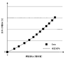
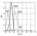
- 6 to 8 show the correlation between the light monitor value detected by the photodiode and the luminance detected by the CCD for each of red light, green light, and blue light in the above-described correlation acquisition processing procedure. ing. 6 to 8 are shown on the same scale on the vertical axis and the horizontal axis.
- the gradients of the calibration equations Fr, Fg, and Fb calculated from the data acquired with the light of each color are the smallest for red light, the largest for blue light, and the largest for green light. That is, the light monitor values Qr, Qg, and Qb having the same luminance Lr, Lg, and Lb detected by the light receiving unit 230 for each color light have the smallest red light, then the largest blue light, and the most green light. It is getting bigger.
- the red light source control unit 110 ⁇ / b> R, the green light source control unit 110 ⁇ / b> G, and the blue light source control unit 110 ⁇ / b> B are combined with the light monitor values Qr, Qg, and Qb in the imaging processing device 200.
- the brightness Lr, Lg, Lb detected by the light receiving unit 230 is received.
- the red light source control unit 110R, the green light source control unit 110G, and the blue light source control unit 110B have calibration equations Fr, Fg, and Fb that indicate the correlation between the luminances Lr, Lg, and Lb and the light monitor values Qr, Qg, and Qb. To get.
- the illumination device 100 and the image acquisition system 10 each adjusts the amount of light emitted from the red light source 130R, the green light source 130G, and the blue light source 130B based on the calibration formulas Fr, Fg, and Fb.
- the emitted light can be combined to adjust the white balance of the illumination light.
- the power consumption of each light source can be reduced by adjusting the white balance of the illumination light by adjusting the light amounts of the RGB light sources instead of adjusting the gain of the light receiving unit 230.
- the white balance of the illumination light is adjusted by adjusting the amount of light of the RGB light source, thereby referring to the image acquired by the imaging processing apparatus 200 each time.
- the white balance of the illumination light can be adjusted accurately.
- the illumination device 100 and the image acquisition system 10 show the correlation between the light monitor values Qr, Qg, Qb and the luminances Lr, Lg, Lb detected by the light receiving unit 230 when, for example, the endoscope probe is attached.
- the calibration equations Fr, Fg, Fb to be expressed are obtained.
- the white balance of the illumination light can be easily adjusted without considering the influence of individual differences in the endoscope probe.
- the white balance of the illumination light can be accurately adjusted by obtaining the calibration equations Fr, Fg, and Fb when each endoscopic probe is mounted. . Therefore, for example, in an endoscope system used in a medical field, a desired captured image suitable for an imaging target can be obtained regardless of individual differences in endoscope probes.
- the illumination device 100 and the image acquisition system 10 each include two white light sources 130W and RGB light sources that can irradiate white light. Therefore, even if one of the light sources fails, the endoscope can be safely taken out from the body while irradiating the other light source with white light having a desired luminance, and each light source can be used as an emergency light. Can function.
- the target values Lr_X, Lg_X, and Lb_X of the luminance of RGB light in the illumination light are set to the same value.
- the above control processing is performed for the RGB light in the illumination light. This can be implemented even when the target value of luminance is different.
- the white light source 130W is A lamp light source such as a xenon lamp or a halogen lamp may be used.
- the second embodiment of the present disclosure is different from the first embodiment in that the white light source, the red light source, the green light source, and the blue light source are driven and controlled by a common control unit.
- the following description will focus on differences from the illumination device according to the first embodiment.
- the illumination device 300 includes a white light source 130W, a red light source 130R, a green light source 130G, a blue light source 130B, a red light source driving circuit 310R, a green light source driving circuit 310G, a blue light source driving circuit 310B, a control unit 330, and a multiplexing unit 170.
- the illumination device 300 includes a red light monitor unit 150R, a green light monitor unit 150G, and a blue light monitor unit 150B.
- the white light source 130W, the red light source 130R, the green light source 130G, and the blue light source 130B can have the same configuration as the light source of the illumination device 100 according to the first embodiment.
- the RGB light source is not limited to a three-color light source, and may be a four-color light source or the like, and the number of light sources is not limited.
- the multiplexing unit 170 can also have the same configuration as the multiplexing unit 170 of the lighting apparatus 100 according to the first embodiment illustrated in FIG.
- the controller 330 controls the drive currents of the white light source 130W, the red light source 130R, the green light source 130G, and the blue light source 130B.
- the red light source 130R, the green light source 130G, and the blue light source 130B are detected by the respective luminance Lr, Lg, and Lb of the red light, the green light, and the blue light detected by the light receiving unit 230 of the imaging processing apparatus 200, and the respective light monitor units.
- the driving current of each light source is set based on the correlation with the optical monitor values Qr, Qg, and Qb.
- the white light source 130W, the red light source 130R, the green light source 130G, and the blue light source 130B can have the same configuration as the light source of the illumination device 100 according to the first embodiment.
- the amount of white light can be controlled by increasing or decreasing the supply current even for the white light source 130W.
- the RGB light source is not limited to a three-color light source, and may be a four-color light source or the like, and the number of light sources is not limited.
- the red light monitor unit 150R, the green light monitor unit 150G, and the blue light monitor unit 150B can have the same configuration as the light monitor unit of the illumination device 100 according to the first embodiment.
- the white light source controller 110W also correlates the luminances Lwr, Lwg, and Lwb detected by the light receiving unit 230 of the imaging processing apparatus 200 with the light monitor value Qw detected by the white light monitor unit 150W. Based on the relationship, the drive current supplied to the white light source 130W is controlled.
- the white light source control unit 110W turns on only the white light source 130W with different amounts of light, and the luminance Lwr, Lwg, Lwb of each color of RGB detected by the light receiving unit 230 at that time and the white color detected by the white light monitor unit 150W.
- the correlation with the light monitor value Qw of light is calculated. That is, the white light source control unit 110W calculates three correlations corresponding to RGB colors. Note that the light receiving unit 230 can split the received white light into light of RGB colors and detect the luminance Lwr, Lwg, and Lwb of the light of each color.
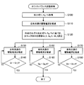
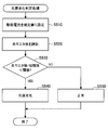
- FIG. 12 shows a flowchart of an example of white balance adjustment processing by the lighting apparatus 400 according to this embodiment.
- This white balance adjustment process is an example of adjusting the amount of light emitted from each light source so that the luminance of light of each color of RGB in the illuminating illumination light becomes preset target values Lr_X, Lg_X, Lb_X. .
- the flow of white balance adjustment processing may be started, for example, when a user presses a white balance adjustment processing start button (not shown).
- step S600 the red light source control unit 110R, the green light source control unit 110G, and the blue light source control unit 110B respectively output the light monitor values Qr, Qg, Qb and the luminance Lr of the emitted light for each of the red light, the green light, and the blue light. , Lg, and Lb are calculated. Similar to the first embodiment, the light monitor values Qr, Qg, Qb of the emitted light from the red light source 130R, the green light source 130G, and the blue light source 130B, and the luminances Lr, Lg, Lb detected by the light receiving unit 230, Calibration formulas Fr, Fg, and Fb representing the correlations are calculated.
- Calibration equations Fwr, Fwg, and Fwb representing the correlation between the optical monitor value Qw and the luminances Lwr, Lwg, and Lwb are calculated.
- the calibration formula can be, for example, a quadratic polynomial, but the method of calculating the calibration formula and the order of the calibration formula can be set as appropriate.
- the calibration formulas Fwr, Fwg, and Fwb for the white light source 130W After calculating the calibration formulas Fwr, Fwg, and Fwb for the white light source 130W, the calibration formulas Fwr, Fwg for the red light source 130R, the green light source 130G, and the blue light source 130B are also performed in accordance with the procedure described in the first embodiment. , Fwb is calculated (steps S210 to S260).
- FIGS. 14 to 16 show the correlation between the light monitor value Qw detected by the photodiode and the luminances Lwr, Lwg, and Lwb detected by the CCD for white light in the above-described correlation acquisition processing procedure.
- the horizontal axis indicates the optical monitor value
- the vertical axis indicates the luminance.
- the vertical axes of FIGS. 14 to 16 are shown on the same scale, and the horizontal axes of FIGS. 14 to 16 are shown on the same scale.
- each control unit obtains calibration equations Fwr, Fwg, Fwb, Fr, Fg, and Fb related to the light emitted from the respective light sources, and then the process proceeds to step S605.
- the white light source control unit 110W based on the calibration formulas Fwr, Fwg, and Fwb, the light monitor values at which the luminances of the RGB colors are all equal to or less than the preset luminance target values Lr_X, Lg_X, and Lb_X. Qw_A is calculated.
- the white light source control unit 110W sets the calculated light monitor value Qw_A as a target value for drive control of the white light source 130W.
- the target values Lr_X, Lg_X, and Lb_X of the luminance of each RGB color during white balance adjustment can be set to 200 (cd / m 2 ), for example.
- the white light source controller 110W increases or decreases the drive current of the white light source 130W in step S610.
- step S615 the white light source control unit 110W determines whether or not the light monitor value Qw detected by the white light monitor unit 150W has reached the target value Qw_A set in step S605.
- the white light source control unit 110W repeats the processing from step S610 to step S615 until the detected light monitor value Qw reaches the target value Qw_A.
- the red light source control unit 110R calculates a difference Lr_A between the target luminance Lr_X of the red light in the illumination light and the red light luminance Lr corresponding to the current light monitor value Qw_A of the white light.
- the green light source control unit 110G and the blue light source control unit 110B also use the luminance Lg_X, Lb_X that is the target of each color light in the illumination light, and the light of each color corresponding to the current light monitor value Qw_A of the white light. Differences Lg_A and Lb_A from the luminances Lg and Lb are calculated.
- step S630 the red light source control unit 110R increases or decreases the drive current of the red light source 130R.
- step S635 the red light source control unit 110R determines whether or not the light monitor value Qr detected by the red light monitor unit 150R has reached the target value Qr_A set in step S625.
- the red light source control unit 110R repeats the processing from step S630 to step S635 until the detected light monitor value Qr reaches the target value Qr_A.
- the light monitor values Qg and Qb detected by the green light monitor unit 150G and the blue light monitor unit 150B become the target values Qg_A and Qb_A set in step S625. Then, increase / decrease and determination of the drive current are repeated (steps S640 to S645, steps S650 to S655).
- the white balance adjustment process ends when the light monitor values Qr, Qg, Qb coincide with the target values Qr_A, Qg_A, Qb_A.
- the endoscope system has, for example, the calibration formulas Fwr and Fwg representing the correlation between the light monitor values of the emitted light of the white light source and the RGB light source and the luminance after the attachment of the endoscope probe. , Fwb, Fr, Fg, Fb are acquired. Thereby, thereafter, the white balance can be easily adjusted without looking at the image acquired by the imaging processing apparatus 200.
- the brightness of the illumination light is corrected mainly by the white light emitted from the white light source 130W and the emitted light emitted from the RGB light source.
- the processing is not limited to such an example. You may make it correct
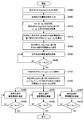
- FIG. 17 shows a flowchart of an example of color temperature adjustment processing by the lighting apparatus 400 according to the present embodiment.
- the flow of this color temperature adjustment process changes the luminance ratio (RGB ratio) of red light, green light, and blue light while maintaining the light quantity (Qx) of the illumination light currently being irradiated. It is the flow of the process which adjusts temperature.
- the white light source control unit 110W calculates the correlation between the light monitor value Qw of the emitted light and the luminances Lwr, Lwg, and Lwb of the RGB colors for white light. Also, the red light source control unit 110R, the green light source control unit 110G, and the blue light source control unit 110B respectively output light monitor values Qr, Qg, Qb and luminances Lr, Lg, Lb for the red light, the green light, and the blue light. Is calculated.
- This step S300 is performed according to the procedure illustrated in FIG. 13 similarly to step S600 of the white balance adjustment process illustrated in FIG. 12, and may be performed when the endoscope probe is attached to the illumination device 400. .
- step S305 the white light source control unit 110W, the red light source control unit 110R, the green light source control unit 110G, and the blue light source control unit 110B receive an input of an instruction for changing the color temperature of the illumination light.
- the instruction to change the color temperature in step S305 is input by, for example, the user setting the RGB ratio or pressing an input switch (not shown) in which the RGB ratio is set in advance.
- step S310 the control unit of each light source detects light monitor values Qw, Qr, Qg, Qb detected by the white light monitor unit 150W, the red light monitor unit 150R, the green light monitor unit 150G, and the blue light monitor unit 150B. Is read respectively.
- the control unit of each light source may exchange the information of the light monitor values Qw, Qr, Qg, Qb, or the control unit of each light source may respectively exchange all the light monitor values Qw, Qr, Qg, Qb. May be read.
- each control unit based on the already calculated calibration formulas Fwr, Fwg, Fwb, Fr, Fg, and Fb, the luminance Lr of each of the RGB colors corresponding to the light monitor values Qw, Qr, Qg, and Qb. Lg, Lb and the total luminance value Ly thereof are calculated.
- the luminance Lr of red light in the illumination light is the sum of the luminance value obtained from the light monitor value Qr based on the calibration formula Fr and the luminance value obtained from the light monitor value Qw based on the calibration formula Fwr. Desired.
- the luminance Lg of green light in the illumination light is also obtained based on the calibration formulas Fg and Fwg.
- the luminance Lb of the blue light in the illumination light can be obtained based on the calibration formulas Fb and Fwb.
- the total luminance value Ly is obtained by adding the obtained luminances Lr, Lg, and Lb.
- the total luminance value Ly is calculated by any one of the white light source control unit 110W, the red light source control unit 110R, the green light source control unit 110G, and the blue light source control unit 110B. You may make it output Ly.
- step S325 the white light source controller 110W increases or decreases the drive current of the white light source 130W.
- step S330 the white light source controller 110W determines whether or not the light monitor value Qw detected by the white light monitor unit 150W has reached the target value Qw_B set in step S320. The white light source control unit 110W repeats the processing from step S325 to step S330 until the detected light monitor value Qw becomes the target value Qw_B.
- the red light source control unit 110R calculates a difference Lr_B between the target luminance Lr_Y of the red light in the illumination light and the red light luminance Lr corresponding to the current white light light monitor value Qw_B. .
- the green light source control unit 110G and the blue light source control unit 110B similarly emit light of each color corresponding to the luminance Lg_Y, Lb_Y that is the target of the light of each color in the illumination light and the current light monitor value Qw_B of the white light. Differences Lg_B and Lb_B from the luminances Lg and Lb are calculated.
- the red light source control unit 110R increases or decreases the drive current of the red light source 130R in step S345.
- the red light source control unit 110R determines whether or not the light monitor value Qr detected by the red light monitor unit 150R in step S350 has reached the target value Qr_B set in step S340.
- the red light source control unit 110R repeats the processing from step S345 to step S350 until the detected light monitor value Qr reaches the target value Qr_B.
- the green light source control unit 110G and the blue light source control unit 110B the light monitor values Qg and Qb detected by the green light monitor unit 150G and the blue light monitor unit 150B become the target values Qg_B and Qb_B set in step S340.
- the increase / decrease and determination of the drive current are repeated (steps S355 to S360, steps S365 to S370).
- the color temperature adjustment process ends when the light monitor values Qr, Qg, Qb and the target values Qr_B, Qg_B, Qb_B match.
- the endoscope system has, for example, the calibration formulas Fwr, Fwg, which represent the correlation between the light monitor values of the emitted light of the white light source and the RGB light source and the luminance after the attachment of the endoscope probe.
- Fwb, Fr, Fg, and Fb are acquired. Thereby, thereafter, the color temperature can be easily adjusted while maintaining the light quantity (Qx) of the illumination light without looking at the image acquired by the imaging processing apparatus 200.
- the luminance of the illumination light is corrected mainly by the white light emitted from the white light source 130W and the emitted light emitted from the RGB light source.
- the processing is not limited to such an example. You may make it correct
- FIG. 18 shows a flowchart of an example of light amount adjustment processing by the lighting apparatus 400 according to the present embodiment.
- the flow of this light amount adjustment process is a process for adjusting the light amount of the illumination light while maintaining the color temperature of the illumination light currently being irradiated, that is, the luminance ratio (RGB ratio) of red light, green light, and blue light. It is a flow of.
- step S410 the control unit of each light source monitors the light monitor values Qw, Qr, Qg, Qb detected by the white light monitor unit 150W, the red light monitor unit 150R, the green light monitor unit 150G, and the blue light monitor unit 150B. Is read respectively.
- the control unit of each light source may exchange the information of the light monitor values Qw, Qr, Qg, Qb, or the control unit of each light source may respectively exchange all the light monitor values Qw, Qr, Qg, Qb. May be read.
- the RGB ratio of the illumination light is calculated by any one of the white light source control unit 110W, the red light source control unit 110R, the green light source control unit 110G, and the blue light source control unit 110B, and the other control units have an RGB ratio. May be output.
- the red light source control unit 110R maintains the RGB ratio of the illumination light, and the total luminance of the red light, the green light, and the blue light is a luminance Lz corresponding to the instructed light amount of the illumination light.
- the target luminance Lr_Z of red light is calculated.
- the green light source control unit 110G and the blue light source control unit 110B maintain the RGB ratio of the illumination light, and the total luminance of the light of each color is the luminance value Lz corresponding to the instructed light amount of the illumination light.
- the target luminances Lg_Z and Lb_Z for green light and blue light are calculated.
- step S430 the white light source control unit 110W determines whether or not the light monitor value Qw detected by the white light monitor unit 150W has reached the target value Qw_C set in step S420. The white light source control unit 110W repeats the processing from step S425 to step S430 until the detected light monitor value Qw reaches the target value Qw_C.
- the red light source control unit 110R calculates a difference Lr_C between the target luminance Lr_Z of the red light in the illumination light and the red light luminance Lr corresponding to the current light monitor value Qw_C of the white light.
- the green light source control unit 110G and the blue light source control unit 110B also use the luminance Lg_Z, Lb_Z that is the target of the light of each color in the illumination light and the light of each color corresponding to the current light monitor value Qw_C of the white light. Differences Lg_C and Lb_C from the luminances Lg and Lb are calculated.
- the red light source control unit 110R increases or decreases the drive current of the red light source 130R in step S445.
- step S450 the red light source control unit 110R determines whether or not the light monitor value Qr detected by the red light monitor unit 150R has reached the target value Qr_C set in step S440.
- the red light source control unit 110R repeats the processing from step S445 to step S450 until the detected light monitor value Qr reaches the target value Qr_C.
- the green light source control unit 110G and the blue light source control unit 110B the light monitor values Qg and Qb detected by the green light monitor unit 150G and the blue light monitor unit 150B become the target values Qg_C and Qb_C set in step S440.
- the increase / decrease and determination of the drive current are repeated (steps S455 to S460, steps S465 to S470).
- FIG. 19 shows a flowchart of an example of the multiplexing ratio adjustment process by the illumination device 400 according to this embodiment.
- the flow of this combining ratio adjustment process is as follows: white light emitted from the white light source 130W and emitted light emitted from the RGB light source while maintaining the light amount and color temperature (RGB ratio) of the illumination light currently being irradiated. (Hereinafter, also referred to as “RGB light”).
- step S820 the control unit of each light source monitors the light monitor values Qw, Qr, Qg, Qb detected by the white light monitor unit 150W, the red light monitor unit 150R, the green light monitor unit 150G, and the blue light monitor unit 150B. Is read respectively.
- the control unit of each light source may exchange the information of the light monitor values Qw, Qr, Qg, Qb, or the control unit of each light source may respectively exchange all the light monitor values Qw, Qr, Qg, Qb. May be read.
- step S830 the white light source control unit 110W calculates a light monitor value Qw_D in which the sum of the luminance Lwr, Lwg, and Lwb of each RGB color becomes the total luminance value Lw_D based on the calibration formulas Fwr, Fwg, and Fwb. To do. Then, the white light source control unit 110W sets the calculated light monitor value Qw_D as a target value for drive control of the white light source 130W.
- the endoscope system has, for example, the calibration formula Fwr, which represents the correlation between the light monitor value of the emitted light of the white light source and the RGB light source and the luminance value when the endoscope probe is attached.
- Fwg, Fwb, Fr, Fg, and Fb are acquired.
- the amount of light emitted from the white light source 130W, the red light source 130R, the green light source 130G, and the blue light source 130B is high. Each is detected by the optical monitor unit.
- calibration formulas Fwr, Fwg, Fwb, Fr, Fg, and Fb indicating the correlation between the luminance detected by the light receiving unit 230 and the light monitor value are acquired for each light source. Is done.
- the light quantity of each light source is calculated based on the calibration formulas Fwr, Fwg, Fwb, Fr, Fg, and Fb without considering the influence of the endoscope probe.
- the light quantity and color temperature of illumination light can be adjusted accurately.
- the illumination device 400 and the image acquisition system 30 can also control the amount of white light to a desired amount of light based on the calibration formulas Fwr, Fwg, and Fwb for the white light source 130W. it can. Thereby, it is possible to accurately adjust the white balance, the color temperature, the light amount, and the multiplexing ratio of the illumination light without referring to the image acquired by the imaging processing apparatus 200 each time.
- the amount of illumination light and the color temperature required vary depending on the user and purpose of use. Further, the user may desire illumination light with a high ratio of white light emitted from the white light source 130W, or may desire illumination light with a high ratio of emission light emitted from the RGB light source. If it is the illuminating device 400 and the image acquisition system 30 which concern on this embodiment, the freedom degree of adjustment, such as the light quantity of the illumination light to irradiate, a color temperature, a multiplexing ratio, will be raised.
- the fourth embodiment of the present disclosure is different from the above-described embodiments in that the control unit of each light source has a function as a deterioration determination unit that determines deterioration of the light source.
- the red light source control unit 110R, the green light source control unit 110G, the blue light source control unit 110B, and the control unit 330 according to the second embodiment according to the first embodiment determine the deterioration of the light source. It may have a function as a part.
- the white light source control unit 110W, the red light source control unit 110R, the green light source control unit 110G, and the blue light source control unit 110B have a function as a deterioration determination unit that determines deterioration of the light source. It may be.
- the illumination device and the image acquisition system according to the present embodiment are basically configured in the same manner as the illumination devices 100, 300, and 400 and the image acquisition systems 10, 20, and 30 shown in FIGS. Can do.
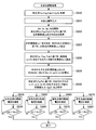
- the illumination device and the image acquisition system according to the present embodiment have a function of determining the deterioration of the light source such that the light amount decreases even when the same current is supplied as the usage period elapses.
- the illumination device 400 and the image acquisition system 30 illustrated in FIG. 10 will be described as an example, and the illumination device and the image acquisition system according to the present embodiment will be described with reference to FIG. 20.
- step S520 the red light source control unit 110R reads the light monitor value Qr detected by the red light monitor unit 150R in a state where a predetermined value of drive current is supplied to the red light source 130R.
- step S530 the red light source control unit 110R supplies the current light monitor value Qr to the initial value Qr0 of the light monitor value detected by supplying the same predetermined current to the red light source 130R at the start of use. It is determined whether or not the ratio R is below a predetermined threshold value R0. If the ratio R is equal to or greater than the threshold value R0 (S530: No), the process proceeds to step S550, and the red light source control unit 110R determines that the red light source 130R is not deteriorated and ends. On the other hand, if the ratio R is less than the threshold value R0 (S530: Yes), the process proceeds to step S540, and the red light source control unit 110R determines that the red light source 130R is deteriorated and ends.
- the white light source control unit 110W, the green light source control unit 110G, and the blue light source control unit 110B also execute the deterioration determination process for the white light source 130W, the green light source 130G, and the blue light source 130B in the same procedure. be able to.
- the control unit 330 can sequentially execute the deterioration determination of each light source according to the procedure shown in FIG.
- the illumination device and the image acquisition system according to the present embodiment described above are provided with light monitor units 150W, 150R, 150G, and 150B that detect the amount of emitted light emitted from each light source. Therefore, each control unit can determine the deterioration of each light source based on the decrease rate of the light monitor values Qw, Qr, Qg, Qb in a state where the same drive current is supplied for each light source. .
- the fifth embodiment of the present disclosure is different from the above-described embodiments in that the amount of emitted light emitted from each of a plurality of light sources is detected by one light monitor unit.
- the following description will focus on differences from the illumination device according to each of the above embodiments.
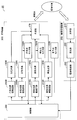
- the illumination device 500 includes a white light source 130W, a red light source 130R, a green light source 130G, a blue light source 130B, a white light source control unit 110W, a red light source control unit 110R, a green light source control unit 110G, a blue light source control unit 110B, and a multiplexing unit 570. Is provided.
- the illumination device 500 includes a color sensor 550 as one light monitor unit.
- the white light source 130W, the red light source 130R, the green light source 130G, and the blue light source 130B can have the same configuration as the light source of the illumination device 100 according to the first embodiment.
- the amount of light can be controlled also for the white light source 130W, but the amount of light of the white light source 130W is constant as in the illumination device 500 according to the first embodiment. May be.
- the RGB light source is not limited to a three-color light source, and may be a four-color light source or the like, and the number of light sources is not limited.
- the multiplexing unit 570 combines the white light and the light of each RGB color and emits it as illumination light.
- FIG. 22 is a schematic diagram illustrating a configuration example of a multiplexing module 580 including the multiplexing unit 570 and including the color sensor 550.
- the combining unit 570 of the illumination device 500 includes a dichroic mirror 571 that reflects a part of the light that is combined and collected by the lens 159 and changes the path in the direction of the color sensor 550. Prepare.
- the amount of light emitted from each light source is not detected by an individual light monitor unit, but the combined light is made incident on the color sensor 550, and each color sensor 550 causes the individual light monitoring unit to enter each individual light. The amount of light is detected.
- FIG. 24 shows an example of spectral sensitivity characteristics of the color sensor 550.
- the incident light passes through each filter to cut light having a wavelength in the infrared region, and is split into light having each wavelength of red light, green light, and blue light. The amount of light can be detected. Further, the color sensor 550 having the configuration shown in FIG. 23 can detect the amount of clear light that does not pass through the filter.
- the amount of light detected by the light detection unit 572 is converted into a voltage signal as the amount of red light and transmitted to the red light source control unit 110R.
- the amount of light detected by the light detection unit 574 is converted into a voltage signal as the amount of green light and transmitted to the green light source control unit 110G.
- the amount of light detected by the light detection unit 576 is converted into a voltage signal as the amount of blue light and transmitted to the blue light source control unit 110B.
- the amount of light detected by the light detection unit 578 is converted into a voltage signal as the amount of white light and transmitted to the white light source control unit 110W.
- the red light source control unit 110R, the green light source control unit 110G, and the blue light source control unit 110B can basically have the same configuration as the control unit of each light source of the illumination device 100 according to the first embodiment. That is, the control unit of each RGB light source correlates the luminance Lr (Lg, Lb) detected by the light receiving unit 230 of the imaging processing apparatus 200 and the light monitor value Qr (Qg, Qb) detected by the color sensor 550. (Calibration formula) is calculated. Moreover, the control part of each RGB light source controls the drive current of each light source based on this correlation.
- the white light source control unit 110W can basically have the same configuration as the white light source control unit 110W of the illumination device 400 according to the third embodiment. That is, the white light source control unit 110 ⁇ / b> W is based on the correlation between the luminance Lwr, Lwg, and Lwb detected by the light receiving unit 230 of the imaging processing apparatus 200 and the light monitor value Qw detected by the color sensor 550. The drive current supplied to 130 W is controlled. Further, the white light source control unit 110W turns on only the white light source 130W with different amounts of light, and is detected by the luminances Lwr, Lwg, Lwb of RGB colors detected by the light receiving unit 230 at that time and the white light monitor unit 150W.
- the correlation with the light monitor value Qw of white light is calculated. That is, the white light source control unit 110W calculates three correlations corresponding to RGB colors. Note that the light receiving unit 230 can split the received white light into light of RGB colors and detect the luminance Lwr, Lwg, and Lwb of the light of each color.
- the illumination device 500 detects the amount of emitted light emitted from each light source with one color sensor (light monitor unit) 550, and performs each control process exemplified in the illumination device according to each of the above embodiments. Can be executed. Therefore, according to the illuminating device 500 and the image acquisition system 40 which concern on this embodiment, the effect similar to the effect acquired by the illuminating device and image acquisition system which concern on each said embodiment can be acquired.
- the luminances Lr_X, Lg_X, and Lb_X of the RGB colors in the illumination light are set in advance.
- the present technology is not limited to such an example.
- appropriate brightness Lr_X, Lg_X, Lb_X may be set by the user during the white balance adjustment process.
- the white light source control unit, the red light source control unit, the green light source control unit, the blue light source control unit, or the control unit calculates the calibration formula.
- the arithmetic processing unit that calculates the calibration formula may be a separate device from each control unit.
- the luminance of each of the emitted light is set so that each luminance of RGB of the illumination light becomes a desired luminance.
- the light quantity of each of the emitted light is set so that the respective luminances of RGB of the illumination light are the same.
- the control method of the illumination device Based on the correlation between the light amount of each of the emitted light and the luminance acquired from the light receiving unit, the light amount of the illumination light is changed while maintaining the RGB luminance ratio of the illumination light. As described above, the control method of the illumination device according to any one of (10) to (14), wherein the light quantity of each of the emitted light is controlled. (16) Based on the correlation between the amount of each emitted light and the luminance acquired from the light receiving unit, the RGB luminance ratio of the illumination light is changed while maintaining the amount of illumination light. As described above, the control method of the illumination device according to any one of (10) to (15), wherein the light quantity of each of the emitted light is controlled.
- a calculation unit that calculates a correlation between the amount of each emitted light and the luminance detected by the light receiving unit.
Landscapes
- Health & Medical Sciences (AREA)
- Life Sciences & Earth Sciences (AREA)
- Surgery (AREA)
- Physics & Mathematics (AREA)
- Engineering & Computer Science (AREA)
- Optics & Photonics (AREA)
- General Health & Medical Sciences (AREA)
- Medical Informatics (AREA)
- Biophysics (AREA)
- Nuclear Medicine, Radiotherapy & Molecular Imaging (AREA)
- Pathology (AREA)
- Heart & Thoracic Surgery (AREA)
- Biomedical Technology (AREA)
- Veterinary Medicine (AREA)
- Radiology & Medical Imaging (AREA)
- Public Health (AREA)
- Molecular Biology (AREA)
- Animal Behavior & Ethology (AREA)
- Signal Processing (AREA)
- Multimedia (AREA)
- Astronomy & Astrophysics (AREA)
- General Physics & Mathematics (AREA)
- Microelectronics & Electronic Packaging (AREA)
- Endoscopes (AREA)
- Instruments For Viewing The Inside Of Hollow Bodies (AREA)
Abstract
Description
<1.第1の実施の形態(RGB各色の出射光の光量を制御する例)>
[1.1.画像取得システムの全体構成例]
(1.1.1.照明装置の構成例)
(1.1.2.撮像処理装置の構成例)
[1.2.照明装置の制御処理例]
<2.第2の実施の形態(共通の制御部を有する例)>
<3.第3の実施の形態(白色光及びRGB各色の出射光の光量を制御する例)>
[3.1.画像取得システムの全体構成例]
[3.2.照明装置の制御処理例]
(3.2.1.ホワイトバランス調整処理例)
(3.2.2.色温度調整処理例)
(3.2.3.光量調整処理例)
(3.2.4.合波比調整処理例)
<4.第4の実施の形態(光源の劣化判定処理機能を有する例)>
<5.第5の実施の形態(カラーセンサを用いる例)>
[1.1.画像取得システムの全体構成例]
まず、図1を参照して、本開示の第1の実施の形態に係る画像取得システム10の概略構成について説明する。図1は、本実施形態に係る画像取得システム10の全体構成を示すブロック図である。この画像取得システム10は照明装置100と撮像処理装置200とを備え、例えば内視鏡システムとして構成される。ただし、内視鏡システムは画像取得システム10の一例であって、電子顕微鏡システム等の他のシステムであってもよい。
照明装置100は、白色光源130W、赤色光源130R、緑色光源130G、青色光源130B、白色光源制御部110W、赤色光源制御部110R、緑色光源制御部110G、青色光源制御部110B及び合波部170を備える。また、照明装置100は、赤色光モニタ部150R、緑色光モニタ部150G及び青色光モニタ部150Bを備える。
白色光源130Wは、例えば青色LED(Light Emitting Diode)と、当該青色LEDの発光光により励起され黄色光を発光する蛍光体とを備えて構成される。係る白色光源130Wは、キセノンランプやハロゲンランプ等のランプ光源とは異なり、出射される白色光の光量が電気的に調節可能になっている。ただし、白色光源130Wは、上記の例に限られず、白色光を出射できるものであればよい。
赤色光源130Rは、例えばGaInP量子井戸構造レーザダイオード等の半導体レーザからなり、青色光源130Bは、例えばGaInN量子井戸構造レーザダイオード等の半導体レーザからなる。緑色光源130Gは、例えば、半導体レーザによって励起される固体レーザからなる。本実施形態に係る照明装置100では、RGB光源が半導体レーザの制御による3色光源からなり、キセノンランプやハロゲンランプ等のランプ光源とは異なり、出射光の光量が電気的に調節可能になっている。
赤色光モニタ部150R、緑色光モニタ部150G及び青色光モニタ部150Bは、例えばフォトダイオードからなる。赤色光モニタ部150Rは赤色光源130Rの出射光の光量を検出する。緑色光モニタ部150Gは緑色光源130Gの出射光の光量を検出する。青色光モニタ部150Bは青色光源130Bの出射光の光量を検出する。赤色光モニタ部150Rについて説明すれば、フォトダイオードからなる赤色光モニタ部150Rは、赤色光源130Rから出射された出射光(赤色光)の一部を受光し、受光した光の光量を電圧信号に変換して赤色光源制御部110Rに送信する。緑色光モニタ部150G及び青色光モニタ部150Bも同様に、緑色光又は青色光の一部を受光し、受光した光の光量を電圧信号に変換して緑色光源制御部110G又は青色光源制御部110Bに送信する。
合波部170は、白色光源130W、赤色光源130R、緑色光源130G及び青色光源130Bからそれぞれ出射された白色光、赤色光、緑色光及び青色光を合波する。本実施形態に係る照明装置100においては、赤色光、緑色光及び青色光それぞれの光量を調節することにより、赤色光、緑色光及び青色光の輝度Lr,Lg,Lbのバランスが変更される。これにより、白色光との合波後の照明光の色温度が調節される。
図1に示した白色光源制御部110Wは白色光源130Wを駆動制御し、赤色光源制御部110Rは赤色光源130Rを駆動制御する。また、緑色光源制御部110Gは緑色光源130Gを駆動制御し、青色光源制御部110Bは青色光源130Bを駆動制御する。このうち、白色光源制御部110Wは、白色光源130Wに供給する駆動電流を制御する。また、赤色光源制御部110Rは、撮像処理装置200の受光部230により検出される輝度Lrと、赤色光モニタ部150Rにより検出される光モニタ値Qrとの相関関係に基づいて、赤色光源130Rに供給する駆動電流を制御する。緑色光源制御部110G及び青色光源制御部110Bも同様に、撮像処理装置200の受光部230により検出される輝度Lg,Lbと、各色光モニタ部150G,150Bにより検出される光モニタ値Qg,Qbとの相関関係に基づいて、緑色光源130G又は青色光源130Bの駆動電流を制御する。
撮像処理装置200は、光学系210、受光部230、撮像処理部250を備える。光学系210は、照明装置100から照射された照明光を取り込む。本実施形態に係る内視鏡システムの場合、光学系210は、内視鏡プローブの先端に設けられた観察窓を介して、照明光を取り込むようにし得る。
以上、本実施形態に係る画像取得システム10の全体構成例について説明した。次に、本実施形態に係る画像取得システム10における照明装置100の制御処理について説明する。
本開示の第2の実施の形態は、白色光源、赤色光源、緑色光源及び青色光源が共通の制御部により駆動制御される点で、第1の実施の形態とは異なる。以下、第1の実施の形態に係る照明装置と異なる点を中心に説明する。
本開示の第3の実施の形態は、赤色光源、緑色光源及び青色光源だけでなく、白色光源についても、光モニタ部で検出される光量と受光部で検出される輝度との相関関係に基づいて制御される点で、第1の実施の形態とは異なる。以下、第1の実施の形態に係る照明装置と異なる点を中心に説明する。
図10は、本実施形態に係る画像取得システム30の全体構成を示すブロック図である。この画像取得システム10は、第1の実施の形態の画像取得システム10と同様に、照明装置400と撮像処理装置200とを備え、例えば内視鏡システムとして構成される。このうち、撮像処理装置200は、白色光源制御部110Wに対しても信号を出力する点以外は、第1の実施の形態に係る画像取得システム10の撮像処理装置200と同様に構成し得る。
以上、本実施形態に係る画像取得システム30の全体構成例について説明した。次に、本実施形態に係る画像取得システム30における照明装置400の制御処理について説明する。
図12は、本実施形態に係る照明装置400によるホワイトバランス調整処理例のフローチャートを示している。このホワイトバランス調整処理は、照射される照明光におけるRGB各色の光の輝度があらかじめ設定された目標値Lr_X,Lg_X,Lb_Xとなるように、各光源からの出射光の光量を調節する例である。ホワイトバランス調整処理のフローは、例えば、使用者によって、図示しないホワイトバランス調整処理開始ボタンが押下されたときに開始されるようにしてもよい。
図17は、本実施形態に係る照明装置400による色温度調整処理例のフローチャートを示している。この色温度調整処理のフローは、現在照射されている照明光の光量(Qx)を維持したまま、赤色光、緑色光及び青色光の輝度の比(RGB比)を変更して照明光の色温度を調節する処理のフローである。
図18は、本実施形態に係る照明装置400による光量調整処理例のフローチャートを示している。この光量調整処理のフローは、現在照射されている照明光の色温度、すなわち、赤色光、緑色光、青色光の輝度の比(RGB比)を維持したまま、照明光の光量を調節する処理のフローである。
図19は、本実施形態に係る照明装置400による合波比調整処理例のフローチャートを示している。この合波比調整処理のフローは、現在照射されている照明光の光量及び色温度(RGB比)を維持したまま、白色光源130Wから出射される白色光と、RGB光源から出射される出射光(以下、「RGB光」ともいう。)との合波比を調節する処理のフローである。
本開示の第4の実施の形態は、各光源の制御部が、光源の劣化を判定する劣化判定部としての機能を有する点で、上記の各実施の形態とは異なっている。例えば、第1の実施の形態に係る赤色光源制御部110R、緑色光源制御部110G、青色光源制御部110B、及び第2の実施の形態に係る制御部330が、光源の劣化を判定する劣化判定部としての機能を有していてもよい。また、第3の実施の形態に係る白色光源制御部110W、赤色光源制御部110R、緑色光源制御部110G及び青色光源制御部110Bが、光源の劣化を判定する劣化判定部としての機能を有していてもよい。
本開示の第5の実施の形態は、1つの光モニタ部により、複数の光源からそれぞれ出射される出射光の光量を検出する点で、上記の各実施の形態とは異なっている。以下、上記の各実施の形態に係る照明装置と異なる点を中心に説明する。
(1)白色光を出射する白色光源と、それぞれの出射光の光量を独立して調整可能なRGB光源と、前記白色光及び前記出射光を合波して照明光とする合波部と、それぞれの前記出射光の光量を制御する制御部と、を備える、照明装置。
(2)前記RGB光源から出射されるそれぞれの前記出射光の光量を検出する光モニタ部を備える、前記(1)に記載の照明装置。
(3)さらに前記白色光源から出射される前記白色光の光量を検出する光モニタ部を備える、前記(2)に記載の照明装置。
(4)前記制御部は、それぞれの前記出射光の光量と、受光部から取得した輝度と、の相関関係に基づいて、前記出射光の光量を制御する、前記(2)に記載の照明装置。
(5)前記制御部は、それぞれの前記白色光及び前記出射光の光量と、受光部から取得した輝度と、の相関関係に基づいて、前記白色光及び前記出射光の光量を制御する、前記(3)に記載の照明装置。
(6)前記制御部は、それぞれの前記出射光について、前記出射光を異なる光量で出射したときにそれぞれ取得された輝度に基づいて前記相関関係を算出する、前記(4)に記載の照明装置。
(7)前記制御部は、前記白色光を異なる光量で出射したときにそれぞれ取得されたRGBそれぞれの輝度に基づいて、前記白色光の光量とRGBそれぞれの輝度との前記相関関係を算出する、前記(5)に記載の照明装置。
(8)前記白色光源はLED光源であり、前記RGB光源はレーザ光源である、前記(1)~(7)のいずれか1項に記載の照明装置。
(9)前記光モニタ部により検出される光量に基づいて、前記RGB光源の劣化を判定する劣化判定部を備える、前記(2)~(8)のいずれか1項に記載の照明装置。
(10)白色光源から出射された白色光に対して合波する、RGB光源から出射されるそれぞれの出射光の光量を制御し、所望の輝度の照明光とする、照明装置の制御方法。
(11)それぞれの前記出射光の光量と、受光部から取得した輝度と、の相関関係に基づいて、前記出射光の光量を制御する、前記(10)に記載の照明装置の制御方法。
(12)前記白色光の光量と、前記受光部から取得したRGBそれぞれの輝度と、の相関関係に基づいて、前記白色光の光量を制御する、前記(11)に記載の照明装置の制御方法。
(13)それぞれの前記出射光の光量と、受光部から取得した輝度と、の相関関係に基づいて、前記照明光のRGBそれぞれの輝度が所望の輝度となるように、それぞれの前記出射光の光量を制御する、前記(10)~(12)のいずれか1項に記載の照明装置の制御方法。
(14)それぞれの前記出射光の光量と、受光部から取得した輝度と、の相関関係に基づいて、前記照明光のRGBそれぞれの輝度が同一になるように、それぞれの前記出射光の光量を制御する、前記(10)~(12)のいずれか1項に記載の照明装置の制御方法。
(15)それぞれの前記出射光の光量と、受光部から取得した輝度と、の相関関係に基づいて、前記照明光のRGBの輝度の比を維持したままで前記照明光の光量が変更されるように、それぞれの前記出射光の光量を制御する、前記(10)~(14)のいずれか1項に記載の照明装置の制御方法。
(16)それぞれの前記出射光の光量と、受光部から取得した輝度と、の相関関係に基づいて、前記照明光の光量を維持したままで前記照明光のRGBの輝度の比が変更されるように、それぞれの前記出射光の光量を制御する、前記(10)~(15)のいずれか1項に記載の照明装置の制御方法。
(17)それぞれの前記出射光の光量を制御するにあたり、前記所望の輝度の照明光におけるRGBそれぞれの輝度値を超えないように前記白色光の光量を制御した後、それぞれの前記出射光の光量を制御する、前記(10)~(16)のいずれか1項に記載の照明装置の制御方法。
(18)白色光を出射する白色光源と、それぞれの出射光の光量を独立して調整可能なRGB光源と、前記白色光及び前記出射光を合波して照明光とする合波部と、前記照明光を受光する受光部と、それぞれの前記出射光の光量を制御する制御部と、を備える、画像取得システム。
(19)それぞれの前記出射光の光量と、前記受光部により検出された輝度と、の相関関係を算出する算出部を備える、前記(18)に記載の画像取得システム。
(20)前記画像取得システムが、内視鏡システム又は電子顕微鏡システムである、前記(18)又は(19)に記載の画像取得システム。
100,300,400,500 照明装置
110W 白色光源制御部
110R 赤色光源制御部
110G 緑色光源制御部
110B 青色光源制御部
130W 白色光源
130R 赤色光源
130G 緑色光源
130B 青色光源
131 励起光源
133,135 集光レンズ
137 光学結晶
139 共振器ミラー
141 波長変換素子
143 反射部
150W 白色光モニタ部
150R 赤色光モニタ部
150G 緑色光モニタ部
150B 青色光モニタ部
151W,151R,151G,151B 光サンプラ
152 ミラー
153,155,157,571 ダイクロイックミラー
159 レンズ
170 合波部
180 合波モジュール
200 撮像処理装置
210 光学系
230 受光部
250 撮像処理部
310R 赤色光源駆動回路
310G 緑色光源駆動回路
310B 青色光源駆動回路
330 制御部
550 カラーセンサ(光モニタ部)
Claims (20)
- 白色光を出射する白色光源と、
それぞれの出射光の光量を独立して調整可能なRGB光源と、
前記白色光及び前記出射光を合波して照明光とする合波部と、
それぞれの前記出射光の光量を制御する制御部と、
を備える、照明装置。 - 前記RGB光源から出射されるそれぞれの前記出射光の光量を検出する光モニタ部を備える、請求項1に記載の照明装置。
- さらに前記白色光源から出射される前記白色光の光量を検出する光モニタ部を備える、請求項2に記載の照明装置。
- 前記制御部は、それぞれの前記出射光の光量と、受光部から取得した輝度と、の相関関係に基づいて、前記出射光の光量を制御する、請求項2に記載の照明装置。
- 前記制御部は、それぞれの前記白色光及び前記出射光の光量と、受光部から取得した輝度と、の相関関係に基づいて、前記白色光及び前記出射光の光量を制御する、請求項3に記載の照明装置。
- 前記制御部は、それぞれの前記出射光について、前記出射光を異なる光量で出射したときにそれぞれ取得された輝度に基づいて前記相関関係を算出する、請求項4に記載の照明装置。
- 前記制御部は、前記白色光を異なる光量で出射したときにそれぞれ取得されたRGBそれぞれの輝度に基づいて、前記白色光の光量とRGBそれぞれの輝度との前記相関関係を算出する、請求項5に記載の照明装置。
- 前記白色光源はLED光源であり、前記RGB光源はレーザ光源である、請求項1に記載の照明装置。
- 前記光モニタ部により検出される光量に基づいて、前記RGB光源の劣化を判定する劣化判定部を備える、請求項2に記載の照明装置。
- 白色光源から出射された白色光に対して合波する、RGB光源から出射されるそれぞれの出射光の光量を制御し、所望の輝度の照明光とする、照明装置の制御方法。
- それぞれの前記出射光の光量と、受光部から取得した輝度と、の相関関係に基づいて、前記出射光の光量を制御する、請求項10に記載の照明装置の制御方法。
- 前記白色光の光量と、前記受光部から取得したRGBそれぞれの輝度と、の相関関係に基づいて、前記白色光の光量を制御する、請求項11に記載の照明装置の制御方法。
- それぞれの前記出射光の光量と、受光部から取得した輝度と、の相関関係に基づいて、前記照明光のRGBそれぞれの輝度が所望の輝度となるように、それぞれの前記出射光の光量を制御する、請求項10に記載の照明装置の制御方法。
- それぞれの前記出射光の光量と、受光部から取得した輝度と、の相関関係に基づいて、前記照明光のRGBそれぞれの輝度が同一になるように、それぞれの前記出射光の光量を制御する、請求項10に記載の照明装置の制御方法。
- それぞれの前記出射光の光量と、受光部から取得した輝度と、の相関関係に基づいて、前記照明光のRGBの輝度の比を維持したままで前記照明光の光量が変更されるように、それぞれの前記出射光の光量を制御する、請求項10に記載の照明装置の制御方法。
- それぞれの前記出射光の光量と、受光部から取得した輝度と、の相関関係に基づいて、前記照明光の光量を維持したままで前記照明光のRGBの輝度の比が変更されるように、それぞれの前記出射光の光量を制御する、請求項10に記載の照明装置の制御方法。
- それぞれの前記出射光の光量を制御するにあたり、前記所望の輝度の照明光におけるRGBそれぞれの輝度値を超えないように前記白色光の光量を制御した後、それぞれの前記出射光の光量を制御する、請求項10に記載の照明装置の制御方法。
- 白色光を出射する白色光源と、
それぞれの出射光の光量を独立して調整可能なRGB光源と、
前記白色光及び前記出射光を合波して照明光とする合波部と、
前記照明光を受光する受光部と、
それぞれの前記出射光の光量を制御する制御部と、
を備える、画像取得システム。 - それぞれの前記出射光の光量と、前記受光部により検出された輝度と、の相関関係を算出する算出部を備える、請求項18に記載の画像取得システム。
- 前記画像取得システムが、内視鏡システム又は電子顕微鏡システムである、請求項18に記載の画像取得システム。
Priority Applications (4)
| Application Number | Priority Date | Filing Date | Title |
|---|---|---|---|
| JP2016563563A JP6597635B2 (ja) | 2014-12-09 | 2015-10-21 | 照明装置及び照明装置の作動方法並びに画像取得システム |
| EP15868596.6A EP3231352A4 (en) | 2014-12-09 | 2015-10-21 | Illumination device, method for controlling illumination device, and image-acquiring system |
| US15/532,234 US20170272720A1 (en) | 2014-12-09 | 2015-10-21 | Illuminating device, control method for illuminating device, and image acquisition system |
| CN201580065476.6A CN106999028B (zh) | 2014-12-09 | 2015-10-21 | 照明装置、控制照明装置的方法以及图像获取系统 |
Applications Claiming Priority (2)
| Application Number | Priority Date | Filing Date | Title |
|---|---|---|---|
| JP2014-248797 | 2014-12-09 | ||
| JP2014248797 | 2014-12-09 |
Publications (1)
| Publication Number | Publication Date |
|---|---|
| WO2016092958A1 true WO2016092958A1 (ja) | 2016-06-16 |
Family
ID=56107153
Family Applications (1)
| Application Number | Title | Priority Date | Filing Date |
|---|---|---|---|
| PCT/JP2015/079732 WO2016092958A1 (ja) | 2014-12-09 | 2015-10-21 | 照明装置及び照明装置の制御方法並びに画像取得システム |
Country Status (5)
| Country | Link |
|---|---|
| US (1) | US20170272720A1 (ja) |
| EP (1) | EP3231352A4 (ja) |
| JP (1) | JP6597635B2 (ja) |
| CN (1) | CN106999028B (ja) |
| WO (1) | WO2016092958A1 (ja) |
Cited By (5)
| Publication number | Priority date | Publication date | Assignee | Title |
|---|---|---|---|---|
| CN107149461A (zh) * | 2017-04-26 | 2017-09-12 | 上海成运医疗器械股份有限公司 | 用于医用内镜光谱染色照明的led光源及照明方法 |
| CN107995433A (zh) * | 2017-11-07 | 2018-05-04 | 佛山市云米电器科技有限公司 | 灯光辅助系统及方法 |
| WO2018207456A1 (ja) * | 2017-05-08 | 2018-11-15 | ソニー株式会社 | 画像取得システム、画像取得方法、制御装置および制御方法 |
| JP2018198189A (ja) * | 2017-05-25 | 2018-12-13 | 三菱電機エンジニアリング株式会社 | 照明装置 |
| JP2020014718A (ja) * | 2018-07-26 | 2020-01-30 | 富士フイルム株式会社 | 内視鏡用光源装置および内視鏡システム |
Families Citing this family (9)
| Publication number | Priority date | Publication date | Assignee | Title |
|---|---|---|---|---|
| WO2017104307A1 (ja) * | 2015-12-14 | 2017-06-22 | オリンパス株式会社 | 光源装置 |
| JP6408457B2 (ja) * | 2015-12-22 | 2018-10-17 | 富士フイルム株式会社 | 内視鏡システム及び内視鏡システムの作動方法 |
| CN111770717B (zh) * | 2018-02-20 | 2023-11-07 | 富士胶片株式会社 | 内窥镜系统 |
| CN108626683A (zh) * | 2018-03-23 | 2018-10-09 | 常州星宇车灯股份有限公司 | 一种用于rgb激光前照灯的色温检测反馈装置 |
| JP6916768B2 (ja) * | 2018-09-05 | 2021-08-11 | 富士フイルム株式会社 | 内視鏡システム |
| CN110740307A (zh) * | 2019-11-18 | 2020-01-31 | 重庆金山医疗技术研究院有限公司 | 自动白平衡的内窥镜及白平衡参数调节方法 |
| CN112386213B (zh) * | 2021-01-20 | 2021-05-14 | 深圳开立生物医疗科技股份有限公司 | 一种内窥成像方法、装置、设备及存储介质 |
| WO2022193234A1 (zh) * | 2021-03-18 | 2022-09-22 | 苏州晶湛半导体有限公司 | 感光单元及其GaN基图像传感器、显示装置 |
| CN116095903B (zh) * | 2023-02-27 | 2024-02-23 | 山东欣立得光电科技有限公司 | 一种提高通用性的led照明系统 |
Citations (5)
| Publication number | Priority date | Publication date | Assignee | Title |
|---|---|---|---|---|
| JPH01234811A (ja) * | 1988-03-16 | 1989-09-20 | Toshiba Corp | 内視鏡光源装置 |
| JP2008264514A (ja) * | 2007-03-23 | 2008-11-06 | Hoya Corp | 内視鏡用光源装置 |
| JP2011036361A (ja) * | 2009-08-10 | 2011-02-24 | Fujifilm Corp | 内視鏡装置 |
| JP2012050650A (ja) * | 2010-08-31 | 2012-03-15 | Fujifilm Corp | 内視鏡システム及びそのキャリブレーション方法 |
| JP2012066066A (ja) * | 2010-08-24 | 2012-04-05 | Fujifilm Corp | 電子内視鏡システム及び血管情報取得方法 |
Family Cites Families (11)
| Publication number | Priority date | Publication date | Assignee | Title |
|---|---|---|---|---|
| JP4426281B2 (ja) * | 2003-12-25 | 2010-03-03 | 船井電機株式会社 | プロジェクタ装置 |
| JP3806934B2 (ja) * | 2004-03-01 | 2006-08-09 | フジノン株式会社 | 内視鏡システム |
| DE102005054184B4 (de) * | 2005-11-14 | 2020-10-29 | Carl Zeiss Microscopy Gmbh | Multispektrale Beleuchtungsvorrichtung und Messverfahren |
| WO2008106590A2 (en) * | 2007-02-28 | 2008-09-04 | Doheny Eye Institute | Portable handheld illumination system |
| US7682027B2 (en) * | 2007-04-09 | 2010-03-23 | Alcon, Inc. | Multi-LED ophthalmic illuminator |
| US20130053434A1 (en) * | 2009-09-28 | 2013-02-28 | Centre National De La Recherche Scientifique | Irreversible inhibitors useful for the treatment of kinase-related pathologies |
| KR101124269B1 (ko) * | 2010-07-30 | 2012-03-27 | 주식회사 엠지비엔도스코피 | 객체간 알지비 색상차이를 최대화하는 내시경용 엘이디 최적 조명장치 |
| CN101968170B (zh) * | 2010-08-09 | 2013-03-13 | 上海光隧光电科技有限公司 | 采用led补色光的led照明光源装置 |
| US8699138B2 (en) * | 2011-06-01 | 2014-04-15 | Nathaniel Group, Inc. | Multi-wavelength multi-lamp radiation sources and systems and apparatuses incorporating same |
| JP2013125693A (ja) * | 2011-12-15 | 2013-06-24 | Koito Mfg Co Ltd | 車両用灯具 |
| WO2016185647A1 (ja) * | 2015-05-15 | 2016-11-24 | ソニー株式会社 | 光源装置、光源駆動方法、及び観察装置 |
-
2015
- 2015-10-21 US US15/532,234 patent/US20170272720A1/en not_active Abandoned
- 2015-10-21 CN CN201580065476.6A patent/CN106999028B/zh active Active
- 2015-10-21 WO PCT/JP2015/079732 patent/WO2016092958A1/ja active Application Filing
- 2015-10-21 JP JP2016563563A patent/JP6597635B2/ja active Active
- 2015-10-21 EP EP15868596.6A patent/EP3231352A4/en not_active Withdrawn
Patent Citations (5)
| Publication number | Priority date | Publication date | Assignee | Title |
|---|---|---|---|---|
| JPH01234811A (ja) * | 1988-03-16 | 1989-09-20 | Toshiba Corp | 内視鏡光源装置 |
| JP2008264514A (ja) * | 2007-03-23 | 2008-11-06 | Hoya Corp | 内視鏡用光源装置 |
| JP2011036361A (ja) * | 2009-08-10 | 2011-02-24 | Fujifilm Corp | 内視鏡装置 |
| JP2012066066A (ja) * | 2010-08-24 | 2012-04-05 | Fujifilm Corp | 電子内視鏡システム及び血管情報取得方法 |
| JP2012050650A (ja) * | 2010-08-31 | 2012-03-15 | Fujifilm Corp | 内視鏡システム及びそのキャリブレーション方法 |
Non-Patent Citations (1)
| Title |
|---|
| See also references of EP3231352A4 * |
Cited By (8)
| Publication number | Priority date | Publication date | Assignee | Title |
|---|---|---|---|---|
| CN107149461A (zh) * | 2017-04-26 | 2017-09-12 | 上海成运医疗器械股份有限公司 | 用于医用内镜光谱染色照明的led光源及照明方法 |
| WO2018207456A1 (ja) * | 2017-05-08 | 2018-11-15 | ソニー株式会社 | 画像取得システム、画像取得方法、制御装置および制御方法 |
| JPWO2018207456A1 (ja) * | 2017-05-08 | 2020-03-12 | ソニー株式会社 | 画像取得システム、画像取得方法、制御装置および制御方法 |
| US10849486B2 (en) | 2017-05-08 | 2020-12-01 | Sony Corporation | Image acquisition system, image acquisition method, control device, and control method |
| JP7234920B2 (ja) | 2017-05-08 | 2023-03-08 | ソニーグループ株式会社 | 画像取得システム、画像取得方法、制御装置および制御方法 |
| JP2018198189A (ja) * | 2017-05-25 | 2018-12-13 | 三菱電機エンジニアリング株式会社 | 照明装置 |
| CN107995433A (zh) * | 2017-11-07 | 2018-05-04 | 佛山市云米电器科技有限公司 | 灯光辅助系统及方法 |
| JP2020014718A (ja) * | 2018-07-26 | 2020-01-30 | 富士フイルム株式会社 | 内視鏡用光源装置および内視鏡システム |
Also Published As
| Publication number | Publication date |
|---|---|
| JP6597635B2 (ja) | 2019-10-30 |
| EP3231352A4 (en) | 2018-08-08 |
| EP3231352A1 (en) | 2017-10-18 |
| CN106999028A (zh) | 2017-08-01 |
| CN106999028B (zh) | 2020-06-16 |
| US20170272720A1 (en) | 2017-09-21 |
| JPWO2016092958A1 (ja) | 2017-09-14 |
Similar Documents
| Publication | Publication Date | Title |
|---|---|---|
| JP6597635B2 (ja) | 照明装置及び照明装置の作動方法並びに画像取得システム | |
| JP6769527B2 (ja) | 医療用光源装置及び医療用光源装置の制御方法 | |
| US10617287B2 (en) | Endoscope system and endoscope light source apparatus | |
| US8721532B2 (en) | Endoscope apparatus and method for controlling fluorescence imaging apparatus | |
| US9066677B2 (en) | Illumination unit and endoscopic apparatus | |
| JP6072374B2 (ja) | 観察装置 | |
| WO2016125334A1 (ja) | 内視鏡装置 | |
| JPWO2018198507A1 (ja) | 光源システム | |
| US10225446B2 (en) | Image pickup system and light source apparatus | |
| JP2019041947A (ja) | 内視鏡システム | |
| JP2007068699A (ja) | 光源装置 | |
| JPWO2017115552A1 (ja) | 光源装置及び撮像システム | |
| WO2018003263A1 (ja) | 観察装置、および観察装置の制御方法 | |
| JP5538143B2 (ja) | 内視鏡システム | |
| JP2020014718A (ja) | 内視鏡用光源装置および内視鏡システム | |
| US11419488B2 (en) | Endoscope system | |
| JP6630702B2 (ja) | 光源装置及び内視鏡システム | |
| JP2016120026A (ja) | 内視鏡システム及びその作動方法 | |
| JP6586206B2 (ja) | 内視鏡システム及びその作動方法 | |
| JP2023093211A (ja) | 内視鏡用プロセッサ、内視鏡システム | |
| JP2004215025A (ja) | ホワイトバランス補正値設定システムおよび撮像感度調整値設定システム |
Legal Events
| Date | Code | Title | Description |
|---|---|---|---|
| 121 | Ep: the epo has been informed by wipo that ep was designated in this application |
Ref document number: 15868596 Country of ref document: EP Kind code of ref document: A1 |
|
| ENP | Entry into the national phase |
Ref document number: 2016563563 Country of ref document: JP Kind code of ref document: A |
|
| REEP | Request for entry into the european phase |
Ref document number: 2015868596 Country of ref document: EP |
|
| WWE | Wipo information: entry into national phase |
Ref document number: 15532234 Country of ref document: US |
|
| NENP | Non-entry into the national phase |
Ref country code: DE |