WO2016092701A1 - 受動qスイッチレーザ - Google Patents
受動qスイッチレーザ Download PDFInfo
- Publication number
- WO2016092701A1 WO2016092701A1 PCT/JP2014/082987 JP2014082987W WO2016092701A1 WO 2016092701 A1 WO2016092701 A1 WO 2016092701A1 JP 2014082987 W JP2014082987 W JP 2014082987W WO 2016092701 A1 WO2016092701 A1 WO 2016092701A1
- Authority
- WO
- WIPO (PCT)
- Prior art keywords
- repetition frequency
- laser
- bias voltage
- passive
- predetermined
- Prior art date
- Legal status (The legal status is an assumption and is not a legal conclusion. Google has not performed a legal analysis and makes no representation as to the accuracy of the status listed.)
- Ceased
Links
Images


Classifications
-
- H—ELECTRICITY
- H01—ELECTRIC ELEMENTS
- H01S—DEVICES USING THE PROCESS OF LIGHT AMPLIFICATION BY STIMULATED EMISSION OF RADIATION [LASER] TO AMPLIFY OR GENERATE LIGHT; DEVICES USING STIMULATED EMISSION OF ELECTROMAGNETIC RADIATION IN WAVE RANGES OTHER THAN OPTICAL
- H01S3/00—Lasers, i.e. devices using stimulated emission of electromagnetic radiation in the infrared, visible or ultraviolet wave range
- H01S3/10—Controlling the intensity, frequency, phase, polarisation or direction of the emitted radiation, e.g. switching, gating, modulating or demodulating
- H01S3/13—Stabilisation of laser output parameters, e.g. frequency or amplitude
- H01S3/131—Stabilisation of laser output parameters, e.g. frequency or amplitude by controlling the active medium, e.g. by controlling the processes or apparatus for excitation
Definitions
- the present invention relates to a passive Q switch laser used in a laser processing apparatus, a laser illumination apparatus, and the like.
- FIG. 5 is a diagram showing a configuration of a conventional passive Q-switched laser (Patent Documents 1 and 2).
- the conventional passive Q-switched laser shown in FIG. 5 includes an excitation source 1, lenses 2a and 2b, a mirror 5a, a laser medium 3, a saturable absorber 4, and a mirror 5b.
- the mirror 5a, the laser medium 3, the saturable absorber 4, and the mirror 5b constitute an optical resonator.
- the excitation source 1 has a laser diode for excitation, and outputs excitation light having a wavelength of about 808 nm excited by the laser diode to the lens 2a.
- the lenses 2 a and 2 b collect the excitation light from the excitation source 1 and output it to the laser medium 3.
- the laser medium 3 is disposed between the mirror 5a and the mirror 5b, and has an Nd: YAG crystal.
- the Nd: YAG crystal is excited by light having a wavelength of about 808 nm, and transitions from the upper level to the lower level. At this time, a laser beam having a wavelength of about 1064 nm is emitted.
- a mirror 5a is attached to one end of the laser medium 3.
- the mirror 5a transmits light having a wavelength of about 808 nm and reflects light having a wavelength of about 1064 nm with a high reflectance.
- the mirror 5b transmits part of the light having a wavelength of about 1064 nm and reflects the rest.
- the saturable absorber 4 is disposed between the mirror 5a and the mirror 5b, and the transmittance increases with the absorption of the laser light from the laser medium 3.
- the saturable absorber 4 becomes transparent, the Q value of the optical resonator rapidly increases, and laser oscillation occurs to generate pulsed light.
- the laser is excited by QCW (Quasi-Continuous-Wave) in order to suppress the heat generated in the laser medium 3.
- QCW Quadsi-Continuous-Wave
- the excitation power varies from 0 to the maximum of the excitation diode and also to a predetermined power V.
- the repetition frequency of the output laser is the same as the excitation repetition frequency.
- a thermal lens is generated by heat generated in the laser medium 3 of the passive Q switch laser.
- the thermal lens depends on the repetition frequency of QCW excitation. When the repetition frequency is low, the thermal lens is small. When the repetition frequency is high, the thermal lens is proportionally increased.
- the tilt (tilt angle) of the mirror 5b (output mirror) must be readjusted according to the size of the thermal lens in order to stably oscillate the laser.
- the tilt of the mirror 5b is adjusted when the repetition frequency is low, the laser oscillation stops or becomes unstable when the repetition frequency is high. Conversely, if the tilt of the mirror 5b is adjusted when the repetition frequency is high, laser oscillation stops or becomes unstable when the repetition frequency is low. For this reason, in order to obtain stable laser oscillation again, it is necessary to readjust the inclination of the mirror 5b.
- the mirror 5b is adjusted by a specialist at the factory. Therefore, unless the mirror 5b is adjusted at the factory, the repetition frequency range of the QCW-pumped passive Q-switched laser becomes narrow.
- the present invention provides a passive Q-switched laser capable of widening the repetition frequency range and improving the laser performance without readjusting the tilt of the mirror.
- a passive Q-switched laser is arranged between a pump source that outputs pump light and a pair of reflecting mirrors that form an optical resonator, and pump light from the pump source.
- a laser medium that emits laser light by being excited by the laser beam
- a saturable absorber that is disposed between the pair of reflecting mirrors and has a transmittance that increases with absorption of the laser light from the laser medium, and the laser medium.
- a quasi-continuous oscillation unit that outputs a repetition frequency signal for oscillation to the excitation source, wherein the quasi-continuous oscillation unit varies a bias voltage in accordance with a repetition frequency of the repetition frequency signal,
- a bias voltage variable unit for adding to the repetition frequency signal is provided.
- the bias voltage variable unit varies the bias voltage in accordance with the repetition frequency of the repetition frequency signal and adds the variable bias voltage to the repetition frequency signal.
- the size will not change. For this reason, even if the repetition frequency is changed, the repetition frequency range can be widened and the laser performance can be improved without readjusting the tilt of the mirror in order to maintain laser oscillation.
- FIG. 1 is a configuration diagram of a passive Q-switched laser according to Example 1 of the present invention.
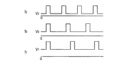
- FIG. 2 is a waveform diagram of a repetition frequency signal of QCW excitation in the passive Q-switched laser of Example 1 of the present invention.
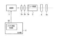
- FIG. 3 is a configuration diagram of a passive Q-switched laser according to Example 2 of the present invention.
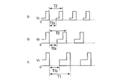
- FIG. 4 is a waveform diagram of a repetition frequency signal of QCW excitation in the passive Q-switched laser according to the second embodiment of the present invention.
- FIG. 5 is a configuration diagram of a conventional passive Q-switched laser.
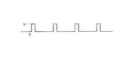
- FIG. 6 is a waveform diagram of a repetition frequency signal of QCW excitation in a conventional passive Q-switched laser.
- FIG. 1 is a configuration diagram of a passive Q-switched laser according to Example 1 of the present invention.
- the passive Q switch laser of Example 1 shown in FIG. 1 includes an excitation source 1, lenses 2a and 2b, a mirror 5a, a laser medium 3, a saturable absorber 4, a mirror 5b, and a QCW unit 6.
- the mirror 5a, the laser medium 3, the saturable absorber 4, and the mirror 5b constitute an optical resonator.
- the passive Q-switched laser of Example 1 shown in FIG. 1 is characterized in that a QCW unit 6 having a bias voltage variable unit 61 is provided with respect to the conventional passive Q-switched laser shown in FIG.
- the QCW unit 6 constitutes a quasi-continuous oscillation unit that outputs a repetition frequency signal for oscillating the laser medium 3 to the excitation source 1.
- the bias voltage variable unit 61 varies the bias voltage (DC voltage) according to the repetition frequency of the repetition frequency signal, and adds the varied bias voltage to the repetition frequency signal.
- the bias voltage variable unit 61 increases the bias voltage above the predetermined voltage when the repetition frequency is lower than the predetermined repetition frequency, and sets the bias voltage when the repetition frequency is higher than the predetermined repetition frequency.
- the voltage is made smaller than a predetermined voltage.
- the value of the bias voltage is set smaller than the laser oscillation threshold, and is set so as not to cause laser oscillation.
- the laser oscillation threshold is determined by the transmittance of the laser medium 3, the saturable absorber 4, and the transmittance of the reflection mirror 5b.
- the bias voltage variable unit 61 sets the bias voltage to V0 and adds it to the signal having the predetermined repetition frequency f0. At this time, the thermal lens has a predetermined size.
- the bias voltage variable unit 61 sets the bias voltage to V1 larger than the predetermined voltage V0 and sets the repetition frequency. Add to the signal of f1. That is, even if the thermal lens is small, by increasing the bias voltage, the thermal lens becomes a predetermined size and does not fluctuate.
- the bias voltage variable unit 61 sets the bias voltage to V2 smaller than the predetermined voltage V0 and sets the repetition frequency. Add to the signal of f2. That is, even if the thermal lens is large, by reducing the bias voltage, the thermal lens becomes a predetermined size and does not fluctuate.
- the bias voltage variable unit 61 varies the bias voltage according to the repetition frequency so that the size of the thermal lens does not vary, and adds the varied bias voltage to the repetition frequency signal.
- the size of the thermal lens is not changed by the variable bias voltage.
- the tilt of the mirror 5b is not readjusted in order to obtain laser oscillation.
- the repetition frequency range can be widened, and the laser performance can be improved. Further, since laser oscillation can be performed stably, the laser output becomes constant.
- FIG. 3 is a configuration diagram of a passive Q-switched laser according to Example 2 of the present invention.
- the passive Q-switched laser according to the second embodiment of the present invention shown in FIG. 3 differs from the passive Q-switched laser according to the first embodiment of the present invention shown in FIG.
- the bias voltage variable unit 62 stops the bias voltage for a predetermined period of one period in each period of the repetitive frequency signal.
- FIG. 4 is a waveform diagram of a repetition frequency signal of QCW excitation in the passive Q-switched laser of Example 2 of the present invention.
- the bias voltage variable unit 62 stops the bias voltage for a predetermined period T0s in one cycle T0, and the remaining period excluding the predetermined period T0s in one cycle T0.
- the bias voltage is set to V0 and added to a signal having a predetermined repetition frequency f0.
- the bias voltage variable unit 62 stops the bias voltage for a predetermined period T1s within one cycle T1, and within one cycle T1. For the remaining period excluding the predetermined period T1s, the bias voltage is set to V1 larger than the predetermined voltage V0 and added to the signal of the repetition frequency f1.
- the bias voltage variable unit 62 stops the bias voltage for a predetermined period T2s within one period T2, and within one period T2. For the remaining period excluding the predetermined period T2s, the bias voltage is set to V2 smaller than the predetermined voltage V0 and is added to the signal of the repetition frequency f2.
- Example 2 the same effect as that of Example 1 can be obtained, and power can be reduced.
- the present invention is applicable to passive Q-switched lasers such as spectroscopic devices, laser processing devices, medical devices, and laser illumination devices.
Landscapes
- Physics & Mathematics (AREA)
- Electromagnetism (AREA)
- Engineering & Computer Science (AREA)
- Plasma & Fusion (AREA)
- Optics & Photonics (AREA)
- Lasers (AREA)
Abstract
受動Qスイッチレーザは、励起光を出力する励起源1と、光共振器を構成する一対の反射ミラー5a,5b間に配置され且つ前記励起源からの励起光により励起させてレーザ光を放出するレーザ媒質3と、前記一対の反射ミラー間に配置され且つ前記レーザ媒質からのレーザ光の吸収に伴って透過率が増加する可飽和吸収体4と、前記レーザ媒質を発振させるための繰り返し周波数信号を前記励起源に出力する準連続発振部6を備え、前記準連続発振部は、前記繰り返し周波数信号の繰り返し周波数に応じてバイアス電圧を可変させ、可変されたバイアス電圧を前記繰り返し周波数信号に加算させるバイアス電圧可変部61を備える。
Description
本発明は、レーザ加工装置、レーザ照明装置などに用いられる受動Qスイッチレーザに関する。
図5は、従来の受動Qスイッチレーザの構成を示す図である(特許文献1,2)。図5に示す従来の受動Qスイッチレーザは、励起源1、レンズ2a,2b、ミラー5a、レーザ媒質3、可飽和吸収体4、ミラー5bを備えている。ミラー5a、レーザ媒質3、可飽和吸収体4、ミラー5bは、光共振器を構成する。
励起源1は、励起用のレーザダイオードを有し、レーザダイオードで励起された波長が約808nmの励起光をレンズ2aに出力する。レンズ2a,2bは、励起源1からの励起光を集光してレーザ媒質3に出力する。
レーザ媒質3は、ミラー5aとミラー5bとの間に配置され、Nd;YAG結晶を有し、Nd;YAG結晶は波長が約808nmの光で励起され、上準位から下準位への遷移の際に波長約1064nmのレーザ光を放出する。
レーザ媒質3の一端には、ミラー5aが取り付けられ、ミラー5aは、波長約808nmの光を透過するとともに、波長約1064nmの光を高反射率で反射する。ミラー5bは、波長約1064nmの光の一部を透過するとともに、残りを反射させる。
可飽和吸収体4は、ミラー5aとミラー5bとの間に配置され、レーザ媒質3からのレーザ光の吸収に伴って透過率が増加する。可飽和吸収体4は、励起準位の電子密度が飽和すると、透明化し、光共振器のQ値が急激に高まりレーザ発振が発生してパルス光が発生する。
この場合、レーザ媒質3に発生する発熱を抑制するために、レーザをQCW(Quasi-Continuous-Wave、準連続発振)で励起している。励起パワーは、図6に示すように、0~励起用ダイオードの最大、また決められた、パワーVまで変化する。このとき、出力レーザの繰り返し周波数は励起繰り返し周波数と同じになる。
また、受動Qスイッチレーザのレーザ媒質3に発生する発熱により熱レンズが発生する。
しかしながら、熱レンズは、QCW励起の繰り返し周波数に依存する。繰り返し周波数が低い場合には、熱レンズが小さく、繰り返し周波数が高くなると、これに比例して熱レンズも大きくなる。
即ち、繰り返し周波数により熱レンズが大きく変わるので、安定にレーザ発振させるためには、熱レンズの大きさに応じて、ミラー5b(出力ミラー)の傾き(傾き角度)を再調整しなければならない。
しかし、繰り返し周波数が低いときに、ミラー5bの傾きを調整した場合には、繰り返し周波数が高いときにはレーザ発振が停止するまたは不安定になる。逆に、繰り返し周波数が高いときに、ミラー5bの傾きを調整した場合には、繰り返し周波数が低いときにはレーザ発振が停止するまたは不安定になる。このため、再度、安定したレーザ発振を得るためには、ミラー5bの傾きの再調整が必要となる。
また、ミラー5bは、工場において専門者によって調整される。従って、工場においてミラー5bの調整を行わない限り、QCW励起の受動Qスイッチレーザの繰り返し周波数範囲は狭くなる。
本発明は、ミラーの傾きを再調整することなく、繰り返し周波数範囲を広くでき、レーザの性能を向上することができる受動Qスイッチレーザを提供する。
上記の課題を解決するために、本発明に係る受動Qスイッチレーザは、励起光を出力する励起源と、光共振器を構成する一対の反射ミラー間に配置され且つ前記励起源からの励起光により励起させてレーザ光を放出するレーザ媒質と、前記一対の反射ミラー間に配置され且つ前記レーザ媒質からのレーザ光の吸収に伴って透過率が増加する可飽和吸収体と、前記レーザ媒質を発振させるための繰り返し周波数信号を前記励起源に出力する準連続発振部を備え、前記準連続発振部は、前記繰り返し周波数信号の繰り返し周波数に応じてバイアス電圧を可変させ、可変されたバイアス電圧を前記繰り返し周波数信号に加算させるバイアス電圧可変部を備える。
本発明によれば、バイアス電圧可変部は、繰り返し周波数信号の繰り返し周波数に応じてバイアス電圧を可変させ、可変されたバイアス電圧を繰り返し周波数信号に加算させるので、可変されたバイアス電圧により熱レンズの大きさが変動しなくなる。このため、繰り返し周波数を変えても、レーザ発振を持続するためにミラーの傾きを再調整することなく、繰り返し周波数範囲を広くでき、レーザの性能を向上することができる。
以下、本発明の実施形態に係る受動Qスイッチレーザを図面を参照しながら詳細に説明する。図1は本発明の実施例1の受動Qスイッチレーザの構成図である。図1に示す実施例1の受動Qスイッチレーザは、励起源1、レンズ2a,2b、ミラー5a、レーザ媒質3、可飽和吸収体4、ミラー5b、QCW部6を備えている。ミラー5a、レーザ媒質3、可飽和吸収体4、ミラー5bは、光共振器を構成する。
即ち、図1に示す実施例1の受動Qスイッチレーザは、図5に示す従来の受動Qスイッチレーザに対して、バイアス電圧可変部61を有するQCW部6を設けたことを特徴とする。
QCW部6は、レーザ媒質3を発振させるための繰り返し周波数信号を励起源1に出力する準連続発振部を構成する。バイアス電圧可変部61は、繰り返し周波数信号の繰り返し周波数に応じてバイアス電圧(直流電圧)を可変させ、可変されたバイアス電圧を繰り返し周波数信号に加算させる。
より具体的には、バイアス電圧可変部61は、繰り返し周波数が所定の繰り返し周波数よりも小さいときはバイアス電圧を所定電圧よりも大きくし、繰り返し周波数が所定の繰り返し周波数よりも大きいときはバイアス電圧を所定電圧よりも小さくする。
なお、バイアス電圧の値は、レーザの発振閾値よりも小さく設定され、レーザ発振させないように設定される。レーザの発振閾値は、レーザ媒質3、可飽和吸収体4の透過率、反射ミラー5bの透過率によって決定される。
次に、このように構成された実施例1の受動QスイッチレーザにおけるQCW励起の動作を図2を参照しながら説明する。
まず、バイアス電圧可変部61は、繰り返し周波数が所定の繰り返し周波数f0のときには、バイアス電圧をV0に設定して所定の繰り返し周波数f0の信号に加算する。このとき、熱レンズは所定の大きさとなる。
次に、バイアス電圧可変部61は、繰り返し周波数が所定の繰り返し周波数f0よりも小さいf1であるときは、熱レンズは小さくなるので、バイアス電圧を所定電圧V0よりも大きいV1に設定して繰り返し周波数f1の信号に加算する。即ち、熱レンズが小さくても、バイアス電圧を大きくすることで、熱レンズが所定の大きさとなり、変動しなくなる。
次に、バイアス電圧可変部61は、繰り返し周波数が所定の繰り返し周波数f0よりも大きいf2であるときは、熱レンズは大きくなるので、バイアス電圧を所定電圧V0よりも小さいV2に設定して繰り返し周波数f2の信号に加算する。即ち、熱レンズが大きくても、バイアス電圧を小さくすることで、熱レンズが所定の大きさとなり、変動しなくなる。
このように、バイアス電圧可変部61は、熱レンズの大きさが変動しないように、繰り返し周波数の大きさに応じて、バイアス電圧を可変させ、可変されたバイアス電圧を繰り返し周波数信号に加算させるので、可変されたバイアス電圧により熱レンズの大きさが変動しなくなる。
従って、繰り返し周波数を変えても、レーザ発振を得るために、ミラー5bの傾きを再調整することがなくなる。また、繰り返し周波数範囲を広くでき、レーザの性能を向上することができる。また、レーザ発振を安定して行えるので、レーザ出力が一定になる。
図3は本発明の実施例2の受動Qスイッチレーザの構成図である。図3に示す本発明の実施例2の受動Qスイッチレーザは、図1に示す本発明の実施例1の受動Qスイッチレーザに対して、バイアス電圧可変部62が異なる。
バイアス電圧可変部62は、繰り返し周波数信号の各周期において1周期の内の所定の期間、バイアス電圧を停止させる。
図4は本発明の実施例2の受動QスイッチレーザにおけるQCW励起の繰り返し周波数信号の波形図である。
バイアス電圧可変部62は、繰り返し周波数が所定の繰り返し周波数f0のときには、1周期T0の内の所定の期間T0s、バイアス電圧を停止させ、1周期T0の内の所定の期間T0sを除く残りの期間、バイアス電圧をV0に設定して所定の繰り返し周波数f0の信号に加算する。
次に、バイアス電圧可変部62は、繰り返し周波数が所定の繰り返し周波数f0よりも小さいf1であるときは、1周期T1の内の所定の期間T1s、バイアス電圧を停止させ、1周期T1の内の所定の期間T1sを除く残りの期間、バイアス電圧を所定電圧V0よりも大きいV1に設定して繰り返し周波数f1の信号に加算する。
次に、バイアス電圧可変部62は、繰り返し周波数が所定の繰り返し周波数f0よりも大きいf2であるときは、1周期T2の内の所定の期間T2s、バイアス電圧を停止させ、1周期T2の内の所定の期間T2sを除く残りの期間、バイアス電圧を所定電圧V0よりも小さいV2に設定して繰り返し周波数f2の信号に加算する。
このように、実施例2においても実施例1の効果と同様な効果が得られるとともに、電力が少なくて済む。
本発明は、分光学装置、レーザ加工装置、医療装置、レーザ照明装置等の受動Qスイッチレーザに適用可能である。
Claims (5)
- 励起光を出力する励起源と、
光共振器を構成する一対の反射ミラー間に配置され且つ前記励起源からの励起光により励起させてレーザ光を放出するレーザ媒質と、
前記一対の反射ミラー間に配置され且つ前記レーザ媒質からのレーザ光の吸収に伴って透過率が増加する可飽和吸収体と、
前記レーザ媒質を発振させるための繰り返し周波数信号を前記励起源に出力する準連続発振部を備え、
前記準連続発振部は、前記繰り返し周波数信号の繰り返し周波数に応じてバイアス電圧を可変させ、可変されたバイアス電圧を前記繰り返し周波数信号に加算させるバイアス電圧可変部を備える受動Qスイッチレーザ。 - 前記バイアス電圧可変部は、前記繰り返し周波数が所定の繰り返し周波数よりも小さいときは前記バイアス電圧を所定電圧よりも大きくし、前記繰り返し周波数が前記所定の繰り返し周波数よりも大きいときは前記バイアス電圧を前記所定電圧よりも小さくする請求項1記載の受動Qスイッチレーザ。
- 前記バイアス電圧可変部は、前記繰り返し周波数信号の各周期において1周期の内の所定の期間、前記バイアス電圧を停止させる請求項1又は請求項2記載の受動Qスイッチレーザ。
- 前記レーザ媒質は、希土類ドープYAGからなる請求項1乃至請求項3のいずれか1項記載の受動Qスイッチレーザ。
- 前記可飽和吸収体は、Cr:YAGからなる請求項1乃至請求項4のいずれか1項記載の受動Qスイッチレーザ。
Priority Applications (2)
| Application Number | Priority Date | Filing Date | Title |
|---|---|---|---|
| JP2016563379A JP6376224B2 (ja) | 2014-12-12 | 2014-12-12 | 受動qスイッチレーザ |
| PCT/JP2014/082987 WO2016092701A1 (ja) | 2014-12-12 | 2014-12-12 | 受動qスイッチレーザ |
Applications Claiming Priority (1)
| Application Number | Priority Date | Filing Date | Title |
|---|---|---|---|
| PCT/JP2014/082987 WO2016092701A1 (ja) | 2014-12-12 | 2014-12-12 | 受動qスイッチレーザ |
Publications (1)
| Publication Number | Publication Date |
|---|---|
| WO2016092701A1 true WO2016092701A1 (ja) | 2016-06-16 |
Family
ID=56106945
Family Applications (1)
| Application Number | Title | Priority Date | Filing Date |
|---|---|---|---|
| PCT/JP2014/082987 Ceased WO2016092701A1 (ja) | 2014-12-12 | 2014-12-12 | 受動qスイッチレーザ |
Country Status (2)
| Country | Link |
|---|---|
| JP (1) | JP6376224B2 (ja) |
| WO (1) | WO2016092701A1 (ja) |
Cited By (1)
| Publication number | Priority date | Publication date | Assignee | Title |
|---|---|---|---|---|
| CN113840680A (zh) * | 2019-05-21 | 2021-12-24 | 索尼集团公司 | 无源q开关激光装置、控制方法及激光处理装置 |
Citations (4)
| Publication number | Priority date | Publication date | Assignee | Title |
|---|---|---|---|---|
| JPS55143088A (en) * | 1979-04-25 | 1980-11-08 | Mitsubishi Electric Corp | Laser actuation |
| US6414980B1 (en) * | 1999-10-12 | 2002-07-02 | Coherent, Inc. | Laser rod thermalization |
| JP2006073962A (ja) * | 2004-09-06 | 2006-03-16 | National Institutes Of Natural Sciences | 受動qスイッチレーザ装置 |
| JP2011192831A (ja) * | 2010-03-15 | 2011-09-29 | Omron Corp | レーザ加工装置、レーザ光源装置、および、レーザ光源装置の制御方法 |
-
2014
- 2014-12-12 WO PCT/JP2014/082987 patent/WO2016092701A1/ja not_active Ceased
- 2014-12-12 JP JP2016563379A patent/JP6376224B2/ja active Active
Patent Citations (4)
| Publication number | Priority date | Publication date | Assignee | Title |
|---|---|---|---|---|
| JPS55143088A (en) * | 1979-04-25 | 1980-11-08 | Mitsubishi Electric Corp | Laser actuation |
| US6414980B1 (en) * | 1999-10-12 | 2002-07-02 | Coherent, Inc. | Laser rod thermalization |
| JP2006073962A (ja) * | 2004-09-06 | 2006-03-16 | National Institutes Of Natural Sciences | 受動qスイッチレーザ装置 |
| JP2011192831A (ja) * | 2010-03-15 | 2011-09-29 | Omron Corp | レーザ加工装置、レーザ光源装置、および、レーザ光源装置の制御方法 |
Cited By (1)
| Publication number | Priority date | Publication date | Assignee | Title |
|---|---|---|---|---|
| CN113840680A (zh) * | 2019-05-21 | 2021-12-24 | 索尼集团公司 | 无源q开关激光装置、控制方法及激光处理装置 |
Also Published As
| Publication number | Publication date |
|---|---|
| JP6376224B2 (ja) | 2018-08-22 |
| JPWO2016092701A1 (ja) | 2017-04-27 |
Similar Documents
| Publication | Publication Date | Title |
|---|---|---|
| CN110854659B (zh) | 双频法拉第半导体激光器及其实现方法 | |
| JP6663913B2 (ja) | 受動qスイッチレーザ及びその動作最適化方法 | |
| US8837535B2 (en) | Microcrystal laser for generating laser pulses | |
| JP2011216662A5 (ja) | ||
| CN107565354B (zh) | 一种ld泵浦的高功率克尔透镜自锁模激光器 | |
| JPWO2017060967A1 (ja) | 波長変換装置 | |
| KR102083267B1 (ko) | 고출력 극초단 펄스 레이저 장치 | |
| CN102891431A (zh) | 一种可以输出圆环状激光分布的固体激光振荡器 | |
| JP2018006365A (ja) | 電流制御装置及びレーザ装置 | |
| JP6376224B2 (ja) | 受動qスイッチレーザ | |
| JP6508058B2 (ja) | 光源装置及び波長変換方法 | |
| JP2011238792A (ja) | 固体レーザ装置 | |
| KR20140044601A (ko) | 고출력 펄스 레이저 장치 | |
| CN105449511A (zh) | 注入锁定腔内倍频固体激光器 | |
| KR20160053799A (ko) | 레이저 시스템 | |
| JP2017204592A (ja) | 受動qスイッチレーザ | |
| JP4071806B2 (ja) | 波長変換装置 | |
| JP6332055B2 (ja) | パルスレーザ装置 | |
| US9203204B2 (en) | Optical frequency multiplication | |
| CN112993733B (zh) | 一种基于Er:YAG中红外光参量振荡器光控波长选择泵浦源 | |
| JP6651718B2 (ja) | Qスイッチレーザ装置 | |
| JP2015035469A (ja) | 固体レーザ装置 | |
| JP5831896B2 (ja) | 光渦レーザービーム発振装置及び発振方法 | |
| US9431790B2 (en) | Intracavity pumped OPO system | |
| JP5164151B2 (ja) | 軸対称偏光レーザー発振装置及び軸対称偏光レーザー発振方法 |
Legal Events
| Date | Code | Title | Description |
|---|---|---|---|
| 121 | Ep: the epo has been informed by wipo that ep was designated in this application |
Ref document number: 14907914 Country of ref document: EP Kind code of ref document: A1 |
|
| ENP | Entry into the national phase |
Ref document number: 2016563379 Country of ref document: JP Kind code of ref document: A |
|
| NENP | Non-entry into the national phase |
Ref country code: DE |
|
| 122 | Ep: pct application non-entry in european phase |
Ref document number: 14907914 Country of ref document: EP Kind code of ref document: A1 |