WO2016084469A1 - バーコード評価装置、バーコード画像生成システム、バーコード評価方法、バーコード画像生成方法及びバーコード評価プログラム - Google Patents
バーコード評価装置、バーコード画像生成システム、バーコード評価方法、バーコード画像生成方法及びバーコード評価プログラム Download PDFInfo
- Publication number
- WO2016084469A1 WO2016084469A1 PCT/JP2015/077327 JP2015077327W WO2016084469A1 WO 2016084469 A1 WO2016084469 A1 WO 2016084469A1 JP 2015077327 W JP2015077327 W JP 2015077327W WO 2016084469 A1 WO2016084469 A1 WO 2016084469A1
- Authority
- WO
- WIPO (PCT)
- Prior art keywords
- barcode
- predetermined
- evaluation
- image
- image display
- Prior art date
- Legal status (The legal status is an assumption and is not a legal conclusion. Google has not performed a legal analysis and makes no representation as to the accuracy of the status listed.)
- Ceased
Links
Images










Classifications
-
- G—PHYSICS
- G06—COMPUTING OR CALCULATING; COUNTING
- G06K—GRAPHICAL DATA READING; PRESENTATION OF DATA; RECORD CARRIERS; HANDLING RECORD CARRIERS
- G06K19/00—Record carriers for use with machines and with at least a part designed to carry digital markings
- G06K19/06—Record carriers for use with machines and with at least a part designed to carry digital markings characterised by the kind of the digital marking, e.g. shape, nature, code
- G06K19/06009—Record carriers for use with machines and with at least a part designed to carry digital markings characterised by the kind of the digital marking, e.g. shape, nature, code with optically detectable marking
- G06K19/06046—Constructional details
- G06K19/06075—Constructional details the marking containing means for error correction
-
- G—PHYSICS
- G06—COMPUTING OR CALCULATING; COUNTING
- G06K—GRAPHICAL DATA READING; PRESENTATION OF DATA; RECORD CARRIERS; HANDLING RECORD CARRIERS
- G06K19/00—Record carriers for use with machines and with at least a part designed to carry digital markings
- G06K19/06—Record carriers for use with machines and with at least a part designed to carry digital markings characterised by the kind of the digital marking, e.g. shape, nature, code
- G06K19/06009—Record carriers for use with machines and with at least a part designed to carry digital markings characterised by the kind of the digital marking, e.g. shape, nature, code with optically detectable marking
- G06K19/06018—Record carriers for use with machines and with at least a part designed to carry digital markings characterised by the kind of the digital marking, e.g. shape, nature, code with optically detectable marking one-dimensional coding
- G06K19/06028—Record carriers for use with machines and with at least a part designed to carry digital markings characterised by the kind of the digital marking, e.g. shape, nature, code with optically detectable marking one-dimensional coding using bar codes
Definitions
- the present invention relates to a barcode evaluation device, a barcode image generation system, a barcode evaluation method, a barcode image generation method, and a barcode evaluation program.
- BARCODE is widely used as a means for transmitting various information.
- the barcode is generally printed on a paper medium.
- the barcode is displayed on the screen of the terminal, and the displayed barcode is displayed by a barcode reader (hereinafter referred to as “barcode scanner” as appropriate). There is an operational need to read the code.
- a bar code is displayed on the screen of a terminal such as a mobile phone, and it can be read by a bar code scanner connected to a cash register at a store or a POS (point of sales) terminal.
- a bar code scanner connected to a cash register at a store or a POS (point of sales) terminal.
- the encoded content of the barcode can be dynamically changed, or the content can be changed for each terminal to be displayed. That is, it can be said that the barcode displayed on the screen of the mobile terminal has a higher degree of freedom than the barcode printed on the paper medium. Furthermore, it is expected that the trouble of printing the barcode and the distribution cost can be reduced by displaying the barcode on the screen of the portable terminal.
- the barcode can be read if it is a combination of a certain model of the mobile terminal and a certain model of the barcode scanner, but the combination of other models cannot read the barcode. This happens.
- Patent Literature 1 and Patent Literature 2 describe techniques for preventing the occurrence of such a situation.
- Patent Document 1 provides a barcode creation method for creating a barcode displayed on a display of a mobile terminal and readable by a barcode reader, a barcode display device for displaying the barcode, and the barcode.
- a bar code providing device is described.
- Patent Document 1 describes that the display method of the barcode is different for each display in consideration of the specifications of the display of the mobile terminal that displays the barcode.
- Patent Document 2 describes a barcode service providing system that prepares a table in which model data of a mobile terminal is associated with barcode image data and displays a barcode image corresponding to the model of the mobile terminal. Has been. That is, cited document 2 also describes that the display method of the barcode is different for each display in consideration of the specifications of the display of the mobile terminal that displays the barcode.
- JP 2002-117372 A Japanese Patent Laid-Open No. 2003-115025
- Patent Document 1 and Patent Document 2 describe that display is performed according to the type of model for displaying the barcode.
- the operation planner provides all the bar code scanners that read the barcode and the mobile terminal that displays the barcode, which the operation planner creates independently for the barcode displayed on the screen on the terminal such as a mobile phone.
- the operation planner creates independently for the barcode displayed on the screen on the terminal such as a mobile phone.
- the screen of the mobile terminal is mainly intended to display information other than the barcode, and is not intended to display the barcode.
- a barcode scanner is mainly intended for reading a barcode printed on paper, and is not intended for reading a barcode displayed on a screen of a portable terminal.
- the operation planner who creates barcodes cannot be controlled to optimize the specifications of the mobile terminal or barcode scanner to the specifications of the barcode that the operation planner wants to use. For this reason, the operation planner who creates the barcode has a reality that it is impossible to predict in advance whether the barcode created by himself / herself can be actually displayed or whether the barcode can be read by the barcode scanner.
- An object of the present invention is to provide a barcode evaluation apparatus, a barcode image generation system, a barcode evaluation method, a barcode image generation method, and a barcode evaluation program that can be performed.
- the evaluation is to determine whether the barcode image can be displayed on the image display device and whether the displayed barcode image can be read by the barcode reader.
- a bar code evaluation apparatus that performs the display without actually displaying and reading based on the contents of the bar code image, the specifications of the image display apparatus, and the specifications of the bar code reading apparatus.
- a barcode image generation system comprising: a barcode image generation requesting device; and the barcode evaluation device provided by the first aspect of the present invention
- the barcode image generation requesting device requests the barcode evaluation device to generate a barcode image having a predetermined content, and the barcode evaluation device determines the content of the barcode image requested to be generated and the result of the evaluation.
- a barcode image generation system that generates a barcode image that can be displayed on a predetermined image display device and that can be read by a predetermined barcode reader.
- a barcode evaluation method performed by a barcode evaluation apparatus, which determines whether a barcode image can be displayed on an image display device and reads a barcode image of a displayed barcode image.
- the evaluation which is to determine whether or not the image can be read, can be performed without actually displaying and reading based on the content of the barcode image, the specification of the image display device, and the specification of the barcode reading device.
- a barcode evaluation method is provided that is characterized in that it is performed.
- a barcode evaluation program comprising: determining whether a bar code image can be displayed on an image display device; and displaying the displayed bar code image on a bar code reader.
- Barcode that performs evaluation that is to determine whether reading is possible or not based on the content of the barcode image, the specifications of the image display device, and the specifications of the barcode reader without actually displaying and reading
- a bar code evaluation program characterized by functioning as an evaluation device is provided.
- a barcode image generation method performed by a system including a barcode image generation requesting device and a barcode evaluation device, wherein the barcode image generation requesting device includes the barcode
- An evaluation apparatus is requested to generate a barcode image having a predetermined content, and the barcode evaluation apparatus is configured to determine whether or not the barcode image can be displayed on the image display apparatus and to display the barcode image displayed on the barcode reading apparatus.
- the evaluation is to determine whether or not reading is possible, based on the content of the barcode image, the specification of the image display device, and the specification of the barcode reading device without actually displaying and reading,
- the barcode evaluation device can display on a predetermined image display device based on the content of the barcode image requested to be generated and the result of the evaluation.
- a bar code image generation method characterized by generating a barcode image that can be read by a predetermined bar code reading device is provided.
- the present invention it is quantitatively evaluated whether or not each of the bar code, the bar code scanner, and the terminal has an appropriate relationship for displaying and reading the bar code without performing verification using an actual machine. It becomes possible to do.
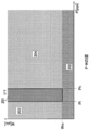
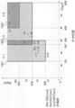
- FIG. 10 is a PW diagram showing an example of a relationship between an appropriate area and a terminal screen specification in the embodiment of the present invention. It is a figure (1/2) explaining in detail about the appropriate area
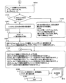
- FIG. 10 is a PW diagram showing an example of a relationship between an appropriate area and a terminal screen specification in the specific example described in the first embodiment of the present invention. It is a flowchart showing the basic operation
- FIG. 17 is a diagram illustrating an example in which a barcode is configured by two lines with the same encoding content as FIG. 16.
- whether or not the “barcode to be displayed” on the screen of the portable terminal can be displayed and read by the barcode scanner that is, whether the barcode scanner and the terminal are “appropriately related” Can be quantitatively evaluated.
- Such evaluation is based on the module width of the “barcode to be displayed” on the screen of the mobile terminal, the specifications of the barcode scanner used for reading, and the screen specifications (pixels) of the mobile terminal assumed to be used, that is, the image display device. Width, pixel density).
- the module width can be derived.
- the black / white pattern (bar space) part included in the barcode is called a barcode symbol.
- a combination of a barcode symbol and left and right margins (margins) is called a barcode.
- the minimum width unit of the barcode symbol is called the minimum module width.
- the module width of the entire barcode is referred to as the overall module width.
- the size of the overall module width is expressed, it is expressed as the overall width XX module (mod) with reference to the minimum module width.
- the overall width of the barcode image obtained by imaging the barcode is a width obtained by multiplying the number of constituent dots per module by the overall module width. For example, in the case of a barcode composed of 100 modules with an overall width, if the image is formed with 1 dot per module, the overall width of the barcode image is 100 dots.
- module width W m the overall module width of the “barcode to be displayed” is W m .
- Module width W m want to use determines the type of bar code, the digits of the character string to be encoded in. Since W m is the overall module width, it includes the width of the barcode symbol and the width of margins (margins) necessary on the left and right.
- the number of constituent dots per module is t (t is a positive integer). Then, t ⁇ W m, which is a value obtained by multiplying the total module width W m of “the barcode to be displayed” by the number of constituent dots t per module, becomes the total dot width of the barcode image.
- CODE128 is standardized as a standard number: JIS X 0504 according to Japanese Industrial Standards (JIS).
- JIS Japanese Industrial Standards
- the character string encoded in CODE SET C of CODE128 is only a number and is in units of two digits.
- the upper limit width of the barcode that can be read by the barcode scanner is defined as W s [mm].
- the minimum resolution that can be read by the barcode scanner, that is, the minimum width that can be detected by the barcode scanner is d s [mm].
- an apparatus having a screen for displaying a barcode is appropriately referred to as a “terminal”. Further, the barcode reader is appropriately referred to as a “barcode scanner”.
- variable list used in this specification is as follows.
- the unit of each variable is assumed to be generally assumed.
- W m The horizontal module width of the barcode to be displayed, and the unit is [mod].
- W m is a positive integer.
- t The number of constituent dots per module of the barcode image, and the unit is [dot / mod].
- t is a positive integer.
- W s The upper limit of the width of the barcode that can be read by the barcode scanner, and the unit is [mm].
- W s is a positive number.
- d s The minimum resolution of the barcode scanner, and its unit is [mm].
- d s is a positive number.
- the width of the constructed barcode is t ⁇ W m ⁇ d [mm]. Since the first condition is that t ⁇ W m ⁇ d does not exceed the readable width W s of the barcode scanner, The expression t ⁇ W m ⁇ d ⁇ W s holds. When this is transformed, the following equation is derived.
- the pixel density of the terminal screen conventionally uses a unit called ppi (pixel per inch) which means the number of pixels per inch as a specification value. And when this unit is used, it becomes as follows.
- This bar code width W m to be displayed is, for not exceeding readable width W s of the bar code scanner, a condition of the terminal pixel density P [ppi].
- the bar code displayed on the terminal screen is not readable by the bar code scanner, regardless of the terminal screen specifications.
- the “unsuitable condition” means that it depends only on the specification value of the barcode scanner. Therefore, considering this condition, it is possible to determine that the barcode is “unsuitable” without comparing the screen specifications of the terminals.
- the module width W m of the bar code is one of the requirements to be a "suitable range”. Furthermore,
- the minimum module width of the displayed bar code is the minimum resolution d of the bar code scanner. below s . Therefore, reading with a barcode scanner becomes impossible. In other words, any terminal screen specification results in a barcode that cannot be read by a barcode scanner.
- the barcode creator needs to take measures such as reducing the number of encoding digits constituting the data, or changing the barcode type so that the module width can be reduced. Also, if you do not reduce the number of encoding digits or change the barcode type, use a barcode scanner that is expected to be used.
- the barcode scanner may be further changed after the number of encoding digits constituting the data is reduced or the barcode type is changed.
- W m is the limit of the overall module width of the barcode in constructing the barcode.
- the module width W m of the bar code so as not to exceed this limit value, the code type and bar code, the encoding digits, etc. It is necessary to decide.
- the module width W m (or tW m ) of the barcode to be displayed fits within the screen width of the terminal to be displayed.
- the width tW m [dot] of the barcode to be displayed exceeds the width W [pix] of the terminal screen. This means that the barcode image can be displayed without protruding on the terminal screen.
- the first condition, the second condition, and the third condition have been described above.
- FIG. 1 is a PW diagram in which the horizontal axis is P [ppi] and the vertical axis is W [dot]
- the first condition, the second condition, and the third condition described above are as follows.
- a description will be given of the PW region to be satisfied, that is, the PW region that satisfies the expressions (A ′), (B ′), and (C).
- FIG. 2-1 is a simplified diagram of FIG.
- the area 201 in FIG. 2 corresponds to the area 101 in FIG.
- Inappropriate factors when the screen specifications k (P k , W k ) of an arbitrary terminal k are plotted in each “inappropriate area” are as follows.
- the areas 211, 212, and 213 in FIG. 2-2 correspond to the areas 101, 102, and 103 in FIG.
- inappropriate areas are classified into 214 areas to 221 areas, and each area has the following “inappropriate factors”.
- the terminal k1 in FIG. 1, which corresponds to the screen specification of the terminal k1, is included in one of the “appropriate areas” described above. That is, the terminal k1 is an example of a terminal that enters the “appropriate area”. If the terminal k1 has a configuration of t 2 [dot / mod], it can display a barcode to be displayed on the screen, and can read within the specification range of the readable width and the minimum resolution of the barcode scanner. It turns out that it is in the range.
- the terminal k1 in FIG. 1 which corresponds to the screen specification of the terminal k2, is not included in one of the “appropriate areas” described above. That is, the terminal k1 is an example of a terminal that does not enter the “appropriate area”.
- the vertical direction of the terminal k2 is W m ⁇ W k2 ⁇ 2W m
- the lateral position is 2P h ⁇ P k2 ⁇ 3P l .
- the minimum module width of the displayed barcode is lower than the specification value of the minimum resolution of the barcode scanner, and the barcode scanner specification assumed to be used cannot be read.
- the appropriate area is U, and the point set of n types of terminals k1, k2,.
- m be the number of terminals k within the appropriate area U, that is, the number of terminals with k ⁇ U.
- an “appropriate ratio” that takes into consideration the configuration specifications of the barcode to be used, the specifications of the barcode scanner, and the terminal screen specifications.
- the quantitative “property rate” value itself can be calculated for the problem “whether the“ barcode you want to use ”is appropriate”. Further, it is possible to perform “evaluation” by comparing the calculated “appropriate rate” with other “appropriate rate” values calculated under other conditions.
- Expression (D) is an expression showing a range of W m necessary for satisfying both of Expression (A ′) and Expression (B ′). As explained as “unsuitable conditions” in the explanation of formula (A ′) and formula (B ′)
- W m The horizontal module width of the barcode to be displayed, and the unit is [mod].
- W m is a positive integer.
- t The number of constituent dots per module of the barcode image, and the unit is [dot / mod].
- t is a positive integer.
- W s The upper limit of the width of the barcode that can be read by the barcode scanner, and the unit is [mm].
- W s is a positive number.
- d s The minimum resolution of the barcode scanner, and its unit is [mm].
- d s is a positive number.
- [Others] d (arbitrary) inter-pixel distance [mm / pix] of the terminal.
- Example 1 is an example relating to an evaluation device for evaluating an image display device and a barcode reader.
- the second embodiment is an embodiment relating to an evaluation apparatus for evaluating a plurality of image display apparatuses and a plurality of barcode reading apparatuses.
- the third embodiment is an embodiment relating to an evaluation apparatus that determines a barcode that can be displayed by a plurality of image display devices and that can be read by a specific barcode reader.
- Embodiment 4 is an embodiment relating to a specification determining device of a barcode reading device that determines the specification of a barcode reading device that reads a specific barcode that can be displayed on a plurality of image display devices.
- Embodiment 5 is an embodiment relating to a barcode image generation system that generates a barcode image to be displayed on an image display device.
- the first embodiment relates to an evaluation apparatus that determines whether or not a barcode to be used can be displayed on a terminal to be displayed and can be read by a barcode scanner assumed to be used.
- the barcode corresponds to the “barcode image” of the present invention.
- the terminal corresponds to the “image display device” of the present invention.
- the bar code scanner corresponds to the “bar code reader” of the present invention.
- the evaluation device corresponds to the “barcode evaluation device” of the present invention.
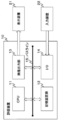
- an evaluation device 10 which is a configuration example of the evaluation device, includes a CPU (Central Processing Unit) 11, a storage device group 12, an image output unit 13, and an I / O (Input / Output) 14. Each unit included in the evaluation device 10 is connected to be communicable with each other via a bus line 15 provided in the evaluation device 10.
- CPU Central Processing Unit
- storage device group 12 includes a storage device group 12, an image output unit 13, and an I / O (Input / Output) 14.
- I / O Input / Output
- a display device 21 is connected to the image output unit 13. Further, an input device 22 is connected to the I / O 14.
- the CPU 11 performs arithmetic processing based on a program stored in the storage device group 12, and controls the entire evaluation apparatus 10 based on the arithmetic result. Similarly, the CPU 11 determines whether or not the barcode to be used can be displayed on the terminal to be displayed and can be read by the barcode scanner assumed to be used.
- the storage device group includes various storage devices. For example, RAM (Random Access Memory ) And auxiliary storage devices such as ROM (Read Only Memory), HDD (Hard disk drive) or SSD (Solid State Drive). These storage devices store variables, programs, and other information necessary for display.
- RAM Random Access Memory
- auxiliary storage devices such as ROM (Read Only Memory), HDD (Hard disk drive) or SSD (Solid State Drive). These storage devices store variables, programs, and other information necessary for display.
- the image output unit 13 is a part that outputs an image in accordance with an instruction from the CPU 11.
- the image signal output from the image output unit 13 is output to the display device 21.
- the display device 21 is a device that allows a user to refer to a determination result as to whether or not a barcode to be used can be displayed on a terminal to be displayed and can be read by a barcode scanner assumed to be used.
- the display device 21 is realized by a liquid crystal display, for example.
- the I / O 14 is a part for connecting an external device to the evaluation apparatus 10.
- an input device 22 is connected to the I / O 14.
- the input device 22 is a device that receives user input, and is realized by a keyboard, for example.
- the user inputs information such as a barcode width, a barcode scanner specification, and a terminal screen specification using the input device 22.
- the input information is input to the evaluation apparatus 10 via the I / O 14. These pieces of information are processed by the CPU 11.
- the evaluation device 10 may be realized as a device specific to the present embodiment, but may be realized by incorporating a program specific to the present embodiment into a general-purpose device such as a personal computer.
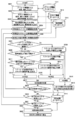
- step S401 step S402 and step S403 input of information necessary for evaluation such as barcode width, barcode scanner specification, and terminal screen specification is accepted.
- the user inputs necessary information using a device such as the input device 22. Then, the evaluation device 10 receives this necessary information via the I / O 14.
- the evaluation device 10 may further include a communication unit for performing data communication via the network. Then, a part or all of necessary information may be acquired from an external device by data communication via the communication unit.
- step S401 the overall module width including information for identifying the barcode to be used (for example, the name of the barcode to be used) and the barcode symbol and the left and right margins of the barcode.
- the input of W m [mod] is accepted.
- step S402 information for identifying the barcode scanner assumed to be used (for example, the name of the barcode scanner assumed to be used), the minimum resolution d s [mm] of the barcode scanner, and the barcode scanner The input of the maximum readable width W s [mm] is accepted.
- step S403 information for identifying a terminal assumed to be used (for example, the name of a terminal assumed to be used), a screen width (number of pixels) W k [pix], and a pixel density, which are screen specifications of the terminal.
- the input of P k [ppi] is accepted.
- the module width W m of the barcode to be used depends on the configuration conditions of “the barcode to be used” such as the code type of the barcode to be used and the number of information digits to be encoded. Therefore, if the information digits such that the type and encoding of the bar code used is determined in advance, it is possible to calculate the module width W m of the bar code to be used in advance.
- step S401 it may accept module width W m itself from the user.
- the user may accept a module width W m calculated in advance based on the configuration conditions of “bar code to be used” such as the code type and the number of information digits to be encoded.
- the evaluation apparatus 10 receives information such as the configuration condition of “bar code to be used” such as the code type and the number of information digits to be encoded, which is necessary for calculating the module width W m from the user. it is also possible to calculate the module width W m.
- a function for performing calculation based on the calculation formula shown in Table 1 is mounted in the evaluation apparatus 10.
- a program for performing a calculation based on the calculation formula shown in Table 1 is stored in the storage device group 12. Then, CPU 11 calculates the module width W m by performing the calculation based on this program.
- Information required for calculating the module width W m for example a user enters at the stage of step S401, the type of code, the number of digits of the data, and necessary information depending on other code (e.g., NW ratio CODABAR etc.) Accept. Then, it Ere calculate the module width W m based on the information.
- step S404 based on the information received in step S401, step S402, and step S403, a barcode suitability determination process is started (step S404).
- step S404 it is first determined whether or not the barcode dimensions are appropriate for the barcode scanner specifications without considering the terminal screen specifications.
- the module width when the barcode having the same width as the readable width W s [mm] of the barcode scanner is configured with the minimum resolution d s [mm] of the barcode scanner as the minimum module width, that is,
- step S404 If this relationship is not established (No in step S404), the process proceeds to step S405.
- the overall barcode width will exceed the barcode scanner's readable width, or less than the barcode scanner's minimum resolution, Cannot read with a barcode scanner.
- step S405 the fact that “the barcode size is incompatible with the barcode scanner specification” is output to the display device 21, the process proceeds to step S412 to make an NG determination, and a series of determination processing ends in step S413.
- step S404 If the above relationship is established (Yes in step S404), the process proceeds to step S406.
- step S406 a bar code with a module width W m input in step S401 it is determined whether it is possible to display on the screen of the terminal with a screen specification input in step S403. Specifically, if the barcode module width W m is equal to or less than the terminal screen width W k , the barcode is “displayable” on the terminal, and otherwise “not displayable”.
- step S406 If “not displayable” in the determination in step S406 (No in step S406), the process proceeds to step S407.
- step S407 the fact that “the barcode cannot be displayed on the terminal screen” is output to the display device 21, the process proceeds to step S412, and the NG determination is made.
- step S413 the series of determination processing ends.
- step S406 if it is determined in 406 that “the barcode can be displayed on the terminal screen” (Yes in step S406), the process proceeds to step S408.
- step S408 the barcode module width W m, when displayed on the terminal screen, the minimum module width of the bar code is greater than the minimum resolution of the bar code scanner and, in the bar code when displayed on the terminal screen It is determined whether or not the width [mm] is equal to or smaller than the readable width of the barcode scanner.
- the minimum module width of the barcode to be displayed is t [dot / mod].
- the maximum value is an integer that becomes 1 [dot / mod], 2 [dot / mod]. At this time, within the possible range of t, the pixel density P k of the terminal
- step S409 the fact that “the barcode can be displayed but cannot be read by the barcode scanner” is output to the display device 21, and the process proceeds to step S412 to determine NG, and a series of determination processing ends in step S413. .
- step S410 the fact that “the barcode can be displayed and can be read by the barcode scanner” is output to the display device 21. In this case, it may be displayed how many values of t at which Equation (A ′) and Equation (B ′) are simultaneously established. Then, the process proceeds to step S411, where an OK determination is made, and a series of determination processes is terminated in step S413.
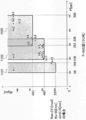
- the formula (A ′) is expressed on the PW plane with the vertical axis representing the terminal screen width W [pix] and the horizontal axis representing the pixel density P [ppi]. This represents a region where both the formula (B ′) and W ⁇ t ⁇ W m are simultaneously established. In this example, an area 501 and an area 502 are shown as areas where all of these are established simultaneously.
- the point corresponding to the pixel density P k [ppi] and the screen width W k [pix] of the terminal targeted for determination processing that is, the screen of the terminal targeted for determination processing Plot the points corresponding to the specification.
- the PW plane is output by a method such as displaying on the display device 21.
- a diagram is displayed in which 503, which is a point corresponding to the screen specifications of the terminal subjected to the determination process, is plotted.
- a barcode having a width W m [mod] can be displayed when attempting to display it on a terminal image having a pixel density P k [ppi] and a screen width W k [pix].
- the barcode scanner with the resolution d s [mm] and the maximum readable width W s [mm] can be read, that is, the relationship between the barcode width, the terminal screen specification, and the barcode scanner specification is “appropriate”. Whether it is visible or not can be visually confirmed by the user who refers to the terminal screen.
- a point k having a pixel density P k [ppi] and a screen width W k [pix] of the terminal is entered in an area where all of the expressions (A ′), (B ′), and W ⁇ t ⁇ W m are simultaneously satisfied. If not, it is understood that it is “inappropriate” for some reason. Furthermore, due to the positional relationship between the point (k) and the region where the equations (A ′) and (B ′) and W ⁇ t ⁇ W m are all established simultaneously, the “cause” and “how much” are not appropriate. It can also be judged.
- the point 504 corresponding to the screen specification of the terminal k1 shown in FIG. 5 does not exist in any of the area 501 and the area 502. That is, the screen specification of the terminal k1 means “not appropriate” in relation to the barcode width and the barcode scanner specification.
- 505 in FIG. 5 which is a point corresponding to the screen specification of the terminal k2 is not in any of the region 501 and the region 502, like 504 which is a point corresponding to the screen specification of the terminal k1. That is, the screen specification of the terminal k2 means “not appropriate” in relation to the barcode width and the barcode scanner specification.
- Example 2 relates to an evaluation apparatus that determines whether a plurality of barcodes desired to be used can be displayed on a plurality of terminals desired to be displayed and can be read by a plurality of barcode scanners assumed to be used.
- a plurality of barcodes, a plurality of barcode scanners, and a plurality of terminals can display a barcode on a terminal screen and comprehensively determine whether the barcode scanner can read the barcode. It is effective as
- the configuration of the evaluation apparatus 10 in the present embodiment is the same as the configuration of the first embodiment described with reference to FIG.
- the processing of the evaluation apparatus 10 when determining whether a certain barcode can be displayed on a certain terminal and can be read by a certain barcode scanner will be described with reference to the flowchart of FIG.
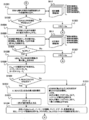
- the process shown in the flowchart of FIG. 6 is a modification of the process in the first embodiment described with reference to FIG. 4, and whether or not it can be read by a plurality of barcodes, a plurality of terminals, and a plurality of barcode scanners. Can be determined.
- steps S601, S602, and S603 input of information necessary for evaluation such as a plurality of barcode widths, a plurality of barcode scanner specifications, and a plurality of terminal screen specifications is accepted.
- the user inputs necessary information using a device such as the input device 22.
- the evaluation device 10 receives this necessary information via the I / O 14.
- the evaluation device 10 may further include a communication unit for performing data communication via the network. Then, a part or all of necessary information may be acquired from an external device by data communication via the communication unit.
- step S601 the entire module including information for identifying the barcode to be used (for example, the name of the barcode to be used), the barcode symbol of the barcode, and the left and right margins of the barcode.
- the input of the width W m [mod] is accepted for a plurality of barcodes.
- step S602 information for identifying the barcode scanner assumed to be used (for example, the name of the barcode scanner assumed to be used), the minimum resolution d s [mm] of the barcode scanner, and the reading of the barcode scanner.
- the input of the maximum possible width W s [mm] is accepted for a plurality of barcode scanners.
- step S603 information for identifying a terminal assumed to be used (for example, the name of the terminal assumed to be used), a screen width (number of pixels) W k [pix], and a pixel density, which are screen specifications of the terminal.
- the input of P k [ppi] is accepted for a plurality of terminals.
- the input information is stored and stored in a predetermined database. Specifically, it is recorded in the barcode information database 12-1, the barcode scanner information database 12-2, and the terminal information database 12-3.
- these three databases are assumed to be realized by any storage device included in the storage device group 12 of the evaluation device 10.
- Information may be input in step S601, step S602, and step S603 executed in accordance with the current process, but part or all of the information to be input is stored in advance in the barcode information database 12-1.
- the bar code scanner information database 12-2 and the terminal information database 12-3 may be recorded.
- the barcode information input in step S601 that is, information for identifying the barcode to be used (for example, the name of the barcode to be used)
- the barcode of the barcode Information such as the entire module width W m [mod] including the code symbol and the left and right margins of the barcode is stored for a plurality of barcodes.
- the module width W m of the bar code to be used similarly to Example 1, the information digits such that the type and encoding of the bar code to be used, depending on the configuration conditions of the "bar code to be used", pre-calculated can do.
- the evaluation apparatus 10 may calculate the module width W m based on the calculation formula shown in Table 1.
- the barcode scanner information input in step S602 that is, information for identifying a barcode scanner assumed to be used (for example, a barcode scanner assumed to be used).
- the minimum resolution d s [mm] of this barcode scanner and the maximum readable width W s [mm] of this barcode scanner are stored for a plurality of barcode scanners.
- the terminal information input in step S603 that is, information for identifying a terminal assumed to be used (for example, the name of the terminal assumed to be used), and the terminal information Information such as screen width (number of pixels) W k [pix] and pixel density P k [ppi], which are screen specifications, is stored for a plurality of terminals.
- each data is handled as the nth data on each of the barcode information database 12-1, the barcode scanner information database 12-2, and the terminal information database 12-3. Further, it is assumed that the CPU 11 of the evaluation apparatus 10 can extract the nth data as necessary. Examples of recording states of the barcode information database 12-1, the barcode scanner information database 12-2, and the terminal information database 12-3 are shown as Table 2, Table 3, and Table 4 below.
- step S604 undetermined barcode width information W m [mod] is extracted from the barcode information database 12-1.
- step S605 the minimum resolution d s [mm] and the maximum readable width W s [mm] of the barcode scanner, which are undetermined barcode scanner specifications, are taken out.
- step S606 the screen width (number of pixels) W k [pix] and the pixel density P k [ppi], which are the screen specifications of the undetermined terminal, are extracted from the barcode scanner information database 12-2.
- undetermined information is extracted every time the determination process is performed, and the determination target is changed, so that a plurality of barcodes, a plurality of barcode scanner specifications, and a plurality of terminal screen specifications can be obtained.
- the determination is made for each combination.
- step S607 it is determined whether the barcode size is appropriate for the barcode scanner specification, regardless of the terminal screen specification.
- the specific determination method is the same as the determination method in step S404 of FIG.
- step S607 If this relationship is not established (No in step S607), the process proceeds to step S608.
- step S608 it is determined that “the barcode size is incompatible with the barcode scanner specification” regardless of the terminal screen specification, and the process proceeds to step S616 to determine NG. Then, in step S619, without a separate confirmation processing terminal specifications, are subject to the determination time, the bar code with a module width W m is a determination result that NG determination result database 12-4 on all terminals Record. Furthermore, after treating that all the terminals have been determined, the process proceeds to step S620 as the next process.
- the determination result database 12-4 is a database that stores determination results.
- the determination result database 12-4 is similar to the three databases of the barcode information database 12-1, the barcode scanner information database 12-2, and the terminal information database 12-3, and the storage device group 12 of the evaluation device 10. It is assumed to be realized by any one of the storage devices included in.
- step S607 If the above relationship is established (Yes in step S607), the process proceeds to step S609.
- step S609 similar to step S406 of FIG. 4 in the first embodiment, is input in step S604, the are the subject of determination this time, the bar code with a module width W m is input in step S606, the targeting of the determination time It is determined whether it can be displayed on the screen of a terminal having a screen specification. Specifically, if the barcode module width W m is equal to or less than the terminal screen width W k , the barcode is “displayable” on the terminal, and otherwise “not displayable”.
- step S609 If “not displayable” in the determination in step S609 (No in step S609), the process proceeds to step S610.
- step S610 it is determined that “the barcode cannot be displayed on the terminal screen”, and the process proceeds to step S615 to determine NG.
- step S617 the determined terminal information, barcode module width information, barcode scanner specification information and determination result are recorded in the determination result database 12-4, and the process proceeds to step S618, which is the next process.
- step S609 determines whether “the barcode can be displayed on the terminal screen” (Yes in step S609). If it is determined in step S609 that “the barcode can be displayed on the terminal screen” (Yes in step S609), the process proceeds to step S611.
- step S611 similar to step S408 of FIG. 4 in the first embodiment, when viewing the bar code of the module width W m as an object of determination this time the terminal screen as an object of determination this time, the minimum module width of the bar code Is larger than the minimum resolution of the barcode scanner that is the object of the current determination, and the width of the barcode when displayed on the terminal screen is less than the readable W s [mm] width of the barcode scanner that is the object of the current determination It is determined whether or not.
- Example 1 the calculation is performed as follows.
- the minimum module width of the barcode to be displayed is t [dot / mod].
- the maximum value is an integer that becomes 1 [dot / mod], 2 [dot / mod]. At this time, within the possible range of t, the pixel density P k of the terminal
- step S612 It is determined whether or not there exists t in which the two expressions are simultaneously established. As a result of the determination, if there is no t for which two expressions are satisfied at the same time, it becomes “unreadable” (No in step S611), and the process proceeds to step S612.
- step S612 it is determined that “the barcode can be displayed but cannot be read by the barcode scanner”, and the process proceeds to step S615 to determine NG. Also, the terminal information, barcode module width information, barcode scanner specification information and determination results determined in step S617 are recorded in the determination result database 12-4. Then, the process proceeds to step S618, which is the next process.
- each data is handled as the nth data on each of the barcode information database 12-1, the barcode scanner information database 12-2, and the terminal information database 12-3. Further, it is assumed that the CPU 11 of the evaluation apparatus 10 can extract the nth data as necessary.
- Tables 2, 3, and 4 show examples of recording states of the barcode information database 12-1, the barcode scanner information database 12-2, and the terminal information database 12-3.
- step S608, step S610, and step S612 may be added as incidental information.
- all of the barcodes to be used, the barcode scanner specifications, and the terminal screen specifications are determined brute-force.
- the total number of determination result records is the number of terminals ⁇ the number of barcode scanners ⁇ the number of barcodes.
- the determination is normally performed for all combinations, but if there is a reason, the determination may be performed for some combinations.
- step S618 among the terminal information input in step S603, that is, the terminals recorded in the terminal information database 12-3, there is a terminal that has not been subjected to the determination processing in steps S609 and S611. To check. At this time, if there is an undetermined terminal (No in step S618), the process returns to step S606, and an undetermined terminal is selected again to perform determination processing. On the other hand, if there is no undetermined terminal (Yes in step S618), the process proceeds to step S620.
- step S620 among the barcode scanner specification information input in step S602, that is, among the barcode scanners recorded in the barcode scanner information database 12-2, the determination processing in step S607 and step S611 is performed. Check if there are any remaining barcode scanners. At this time, if there is an undetermined barcode scanner (No in step S620), the process returns to step S605, and an undetermined barcode scanner is selected again to perform a determination process. On the other hand, if there is no undetermined barcode scanner (Yes in step S620), the process proceeds to step S621.
- step S621 determination processing is performed in step S607, step S609, and step S611 out of the barcode module width information input in step S601, that is, the barcode recorded in the barcode information database 12-1. Check if there are any remaining barcodes. At this time, if there is an undetermined barcode (No in step S621), the process returns to step S604, and an undetermined barcode is selected again to perform a determination process. On the other hand, if there is no undetermined barcode (Yes in step S621), the process proceeds to step S622.
- “Yes” in step S621 means that all combinations of the barcode to be used, the barcode scanner specification, and the terminal screen specification have been determined. Therefore, the determination process ends at this stage.
- step S622 the determination result is output based on the determination result recorded in the series of determination processes (information stored in the determination result database 12-4). For example, the output is performed by displaying the determination result on the display device 21.
- all of the recorded information in the determination result database 12-4 may be output, but may be displayed in a list format by bar code scanner type and bar code width.
- An example of the result display in this case is as shown in Table 6 below.
- a value obtained by dividing the number of terminals whose determination result is “OK” by the number of terminals to be determined is defined as a “matching rate” and calculated. be able to. Further, the calculated “adaptation rate” can also be output to the user, for example.
- the conformity rate is 1 when the determination result is OK.
- the accuracy rate becomes smaller than 1 as the number of terminals whose determination result is not OK increases. That is, it can be said that a value closer to 1 has a better “matching rate”. It is possible to determine which bar code scanner type and bar code width combination is most preferable by comparing the values of the “accuracy rate” under each condition.
- the determination processing result may be visualized and visually displayed. More specifically, a PW plane having a terminal screen density P on the horizontal axis and a terminal screen width W on the vertical axis is created for each barcode scanner type and barcode width. And the suitable area
- [mm] and a readable width of 60 [mm] one type
- the results determined according to the processing described in the flowchart of FIG. 6 are plotted on the PW plane.
- the existence rate (or operation rate) which is the ratio of the quantity of each terminal scheduled to be used
- the existence ratio information can be taken into account.
- the calculated “effective adaptation rate” can be output to the user, for example.
- the presence rate (or operation rate) of the terminal determined to be OK is added to calculate the “effective relevance rate” considering the presence rate (or operation rate) of the terminal.
- Effective relevance ratio is higher when the determination is OK at a terminal having a large number (or operating a large number) than when the determination is OK at a terminal having a small number (or a few operating).
- the effective conformance ratio is 0.62.
- step S623 If the result is displayed in step S622, the process proceeds to step S623 and the process is terminated. Further, when data is newly registered in each of the reference information database, that is, the barcode information database 12-1, the barcode scanner information database 12-2, and the terminal information database 12-3 (steps S601 through S601 again). In the case where any or all of step S603 is performed), the determination result is also different. In such a case, in order to make a determination based on the new data, the reference source database may be referred to again to make a determination again and output the determination result (again, step S604). Thru
- a plurality of barcodes, a plurality of barcode scanners, and a plurality of terminals determine whether a barcode can be displayed on the terminal screen and can be read by the barcode scanner. Can do.
- Example 3 will be described.
- the present invention relates to an evaluation apparatus for determining the module width (or the number of encoded digits of a barcode).
- This embodiment is effective as a means for realizing the purpose of increasing the width (number of encoded digits) of a barcode symbol as much as possible within a range that can be displayed on a terminal and read by a barcode scanner.
- the configuration of the evaluation apparatus 10 in the present embodiment is the same as that of the first embodiment and the second embodiment described with reference to FIG.
- the input of the bar code type and the accompanying information which are information necessary for calculating the module width, is received (step S801).
- the type of barcode is, for example, CODE128 or CODABAR.
- the supplementary information is, for example, CodeSetC for CODE128, NW ratio, and gap between characters for CODABAR.
- step S802 information on a barcode scanner to be examined is received. Specifically, information for identifying the barcode scanner (for example, the name of the barcode scanner), the minimum resolution d s [mm] that is “specification of the barcode scanner assumed to be used”, and the maximum readable width The input of W s [mm] is accepted.
- the bar code information database 12-1 and the bar code scanner information database 12-2 in the present embodiment are the same as the bar code information database 12-1 and the bar code scanner information database 12-2 in the second embodiment, respectively. It is assumed to be realized by any storage device included in the storage device group 12 of the yes evaluation device 10.
- the evaluation apparatus 10 may further include a communication unit for performing data communication via the network. Then, part or all of the information stored in the barcode scanner information database 12-2 may be acquired from an external device by data communication via the communication unit.
- step S803 it is calculated on the basis of the maximum value W b of the module width of the bar code to be verified in specification information of the bar code scanner.
- W b be the maximum value of W m that satisfies the following condition.
- the maximum module width W b of the barcode is
- W b is the maximum module width of the barcode to be verified.
- the calculating the minimum value W a module width of the bar code to be verified from the specification information of the bar code scanner is calculated based on the following concept.
- a suitable area can be shown from the barcode module width and the barcode scanner specification.
- the gap width g of the left and right compatible region when the number of dots per module t [dot / mod] can be expressed by the following equation.
- W a be the maximum value of W m that satisfies this condition. That is, the minimum module width W a of the barcode is
- W a is the maximum value at which the width of the “gap” is 0 or less. As W m becomes larger than this value, the number of “non-conforming” terminals increases.
- the module width W of the barcode in the range is determined as the inspection target (step S805).
- the verification is performed with the module width W of the barcode in the range.
- an expression for calculating the overall module width W of the barcode with respect to the number of digits n (integer) is obtained by referring to the calculation type storage unit 12-5 for each barcode type.
- the formula for calculating the overall module width W of the barcode with respect to the number of digits n (integer) differs depending on the code type information and the incidental information. Therefore, an expression corresponding to the code type information and the incidental information received in step S801 is acquired.
- the barcode type calculation formula storage unit 12-5 stores formulas for calculating the overall module width W of the barcode with respect to the number of digits n (integer) corresponding to various code type information and incidental information. It is a part to do. Specifically, formulas such as those shown in Table 1 are stored in the bar code type calculation formula storage section 12-5.
- the barcode type calculation formula storage unit 12-5 is realized by a storage device included in the storage device group 12 of the evaluation device 10.
- module width W of the bar code may be determined in the range of n a digit encoded digits of n b digits.
- the target bar code type information and incidental information are GS1-128 (EAN- 128) CODESET C
- W 11n / 2 + 66 from the calculation formula of Table 1
- the range of the number of digits of the barcode to be investigated is determined to be 24 to 60 digits.
- step S806 the barcode module width is calculated in the range of the number of digits of the barcode to be investigated, that is, in the range of na digits to nb digits, determined in step S805.
- the formula obtained from the barcode type calculation formula storage unit 12-5 is used.
- the barcode information database 12-1 is equivalent to the barcode information database 12-1 in the second embodiment, and any one of the storages included in the storage device group 12 of the evaluation device 10 is used. It shall be realized by the device.
- the type information of the target barcode is GS1-128 (EAN-128).
- EAN-128 the number of digits to be investigated is 24 to 60 digits (even digits). Therefore, 19 types of barcodes can be assumed by calculating the barcode width from the number of digits as described in Table 9 below. In step S806 of FIG. 8, these bar code information is recorded in the “bar code information database 12-1.”
- step S603 in FIG. 6 is called to utilize the processing described in the flowchart in FIG. 6 used in the second embodiment. Then, the processing described in the flowchart of FIG. 6 from step S603 in FIG. 6 is performed, the specification information of the assumed terminal is input, and the evaluation processing is performed in the same manner as in the second embodiment.
- the barcode scanner specification information uses the information received in step S802 and stored in the barcode scanner information database 12-2. Further, the information stored in the barcode information database 12-1 in step S806 is used for the barcode module width information.
- the process returns to step S808 of FIG. 8 to analyze the result. From the processing results of the processing described in the flowchart of FIG. 6, the matching rate for each barcode module width is calculated as in the second embodiment, and the calculation results are displayed on the display device 21.
- the target barcode type and accompanying information are GS1-128 (EAN-128) CODESET C.
- the number of digits to be investigated is 24 to 60 digits (even digits).
- the terminal specifications assumed to be displayed are k1 to k12 in Table 7. In this case, the verification result is as shown in Table 10 below.
- FIG. 9 is a graph showing the number of digits on the horizontal axis and the precision on the vertical axis.
- step S809 an optimum value is derived from the relationship between the number of encoded digits of the barcode and the relevance rate that has been clarified in step S808. Specifically, the optimum value is determined by searching for a condition with the highest relevance rate. Also, if there are a plurality of conditions with the highest precision, the optimum value is determined by searching for the condition with the largest number of digits.
- the condition with the largest number of digits of 1.0 which has the highest precision is the case where the number of digits is 30 digits. . That is, in this case, the optimum value is the condition that the number of digits is 30 digits and the barcode module width is 231 [mod].
- step S810 when the optimum barcode conditions are determined and the result is output in step S809, the process ends in step S810.
- the case of 30 digits is smaller in the area of the terminal specification conforming area (1101 area, 1102 area, and 1103 area), but all points indicating the specifications of the assumed terminal are “conformity”. It can be seen that it falls within the “region”.
- “30 digits” has as many digits as possible in consideration of the specifications of the terminal, that is, in the area 1101 in FIG. 11 and the area 1102 in FIG. This is the number of digits derived so that the point indicating the specification does not deviate.
- the third embodiment may be realized as a single device including the function as the third embodiment, or may be realized as one function of the device including the function as the first or second embodiment. That is, the third embodiment may be combined with the first and second embodiments.
- step S603 in FIG. 6 when combined with the first embodiment instead of being combined with the second embodiment or when combined with the first embodiment, the same processing is realized instead of calling the processing after step S603 in FIG. 6 in step S807.
- a program or the like for this purpose is installed in the apparatus, and the process of step S603 in FIG. 6 may be executed based on this program.
- the barcode symbol width (as much as possible) within a range that can be displayed on the terminal and read by the barcode scanner. There is an effect that the number of encoding digits) can be increased.
- Example 4 is a specification of a barcode scanner capable of reading a barcode when a barcode can be displayed on the terminal on a plurality of terminals assuming barcode display of a specific module width and barcode.
- the present invention relates to a barcode scanner specification specifying device for determining
- a bar code required for reading a bar code of a specific module width and a bar code that can be displayed on the terminal on a plurality of terminals that are supposed to display the bar code is an effective means to realize the purpose of knowing the specifications of the code scanner.
- the barcode scanner specification specifying device 10 ' includes a CPU 11', a storage device group 12 ', an image output unit 13', and an I / O 14 '. Each part included in the barcode scanner specification specifying device 10 'is connected via a bus line 15' provided in the barcode scanner specification specifying device 10 '.
- a display device 21 is connected to the image output unit 13 ′, and an input device 22 is connected to the I / O 14 ′.
- the configuration of the barcode scanner specification specifying device 10 ′ is not illustrated, it is the same as the configuration of the evaluation device 10 of FIG. 3, and the CPU 11 ′, the storage device group 12 ′, and the image output unit of the barcode scanner specification specifying device 10 ′.
- Reference numeral 13 ′, I / O 14 ′, and bus line 15 ′ correspond to the CPU 11, storage device group 12, image output unit 13, I / O 14, and bus line 15 of the evaluation apparatus 10, respectively.
- each part in the barcode scanner specification specifying device 10 ′ is the same as that of each part of the same name included in the evaluation device 10 of the first, second, and third embodiments described with reference to FIG. Since it is the same as the function, the description thereof will be omitted.
- step S1201 the information for identifying the bar code of the "bar code of a fixed module width" (e.g., the name of the bar code), receives an input of the module width W m.
- Each received information is stored in the barcode information database 12-1, and the process proceeds to step S1202.
- the barcode information database 12-1 and the terminal information database 12-3 in the present embodiment are the same as the barcode information database 12-1 and the terminal information database 12-3 in the second and third embodiments, respectively. It is assumed to be realized by any one of the storage devices included in the storage device group 12 ′ of the barcode scanner specification specifying device 10 ′.
- step S1202 information on a terminal assumed to be used, that is, information for identifying the terminal (for example, the name of the terminal), screen width W k [pix], and pixel density P k [ppi] are input. Accept.
- Each received information is stored in the terminal information database 12-3, and the process advances to step S1203. It should be noted that input in either or both of step S1201 and step S1202 may be received in advance, and information may be recorded in each database in advance.
- the barcode scanner specification specifying device 10 ′ may further include a communication unit for performing data communication via a network. Then, part or all of the information stored in each database may be acquired from an external device by data communication via the communication unit.
- step S1203 the terminal information database 12-3 is searched and the maximum value W kmax of the terminal screen width is searched and extracted, and the barcode module width W m of a certain module width is determined.
- the maximum terminal screen width W kmax is 1080 [pix] of the terminal k1
- the maximum value t max of the integer t is determined as 3.
- step S1204 a specific analysis is entered.
- step S1205 from the terminal information database 12-3, for the screen width W k of the terminal, A terminal satisfying tW m ⁇ W k ⁇ (t + 1) W m is extracted, and the process proceeds to step S1206.
- the “terminal that satisfies (t + 1) W m ” corresponds to terminals that satisfy 308 ⁇ W k ⁇ 616, that is, six types of terminals k7 to k12.
- step S1206 from among the extracted terminal in step S1205, search the smallest pixel density P k is its value as P ka, the process proceeds to step S1207.
- step S1207 from among the extracted terminal in step S1205, searches the largest value pixel density P k is its value as P kb, proceeds step S1208.
- the smallest pixel density is 165 [ppi] ( ⁇ P ka ) of the terminal k12 and the largest value is 300 [ppi] ( ⁇ P kb ) of the terminal k7.
- step S1208 using the value P ka with the smallest pixel density extracted in step S1206,
- step S1209 using the value P kb having the highest pixel density extracted in step S1207,
- the minimum pixel density is 165 [ppi] ( ⁇ P ka ) of k12
- the maximum pixel density is 300 [ppi] ( ⁇ P kb ) of k7.
- the calculation result recording database 12-6 is a database for storing the calculation results in this embodiment, and is realized by any storage device included in the storage device group 12 ′ of the barcode scanner specification specifying device 10 ′.
- step S1211 it is determined whether the current value of t is greater than or equal to tmax calculated in step S1203.
- step S1211 If the current value of t is less than t max (No in step S1211), the process proceeds to step S1212 to add 1 to the current value of t to obtain a new value of t. Then, the process returns to step S1205, and the processes from step S1205 to step S1210 are performed again using the new value of t.
- step S1211 if the current value of t is equal to or greater than tmax (Yes in step S1211), the process proceeds to step S1213.
- step S1215 the W st value extracted in step S1213 and the d st value extracted in step S1214 are displayed on the display device 21.
- the value displayed at this time is “an ideal barcode scanner in a barcode with a certain module width W m and a plurality of terminals (screen width W k , pixel density P k ) assuming barcode display. (Readable width: maximum value of W st , minimum resolution: minimum value of d st ) ”.
- step S1215 the value of W st and the value of d st are displayed on the display device 21, and then the process proceeds to step S1216 to end the process.
- the barcode scanner specifications (readable width and minimum resolution) calculated as a result are difficult values in terms of technical or cost as a barcode scanner manufacturing technology, the barcode width is reduced. (Reducing the number of digits) or narrowing down the types of terminals that are supposed to be displayed is necessary.
- the fourth embodiment may be realized as a single device including the function as the fourth embodiment, or may be realized as one function of the device including the function as the first to third embodiments. That is, the fourth embodiment may be combined with the first to third embodiments.
- the barcode scanner specifications are determined in consideration of the barcode of a specific module width and the screen specifications of a plurality of terminals that are assumed to display barcodes. Therefore, in this embodiment, it is necessary to read the barcode when the barcode can be displayed on the terminal on the barcode with a specific module width and a plurality of terminals assuming the display of the barcode. There is an effect that it is possible to know the specifications of the barcode scanner.
- the fifth embodiment relates to a system that actually displays a barcode on a terminal screen.
- generating a barcode means generating barcode image data.
- the barcode system 100 includes a terminal group 30, a terminal k31, a first operator server 41, a second operator server 42, a barcode generation server 50, and a line network 60.
- terminals used by the user there are a terminal k31 and other terminals included in the terminal group 30 as terminals used by the user. These terminals are terminals used by users, but the models and the like are various, and naturally the screen specifications are also various.
- the first business server 41 and the second business server 42 are server devices used by businesses that provide services using barcodes.
- the business operator A is using the first business operator server 41 and the business operator B is using the second business operator server 42.
- the service provider A and the service provider B provide services for different purposes, and the types of bar codes and the number of encoded digits used for providing the services are different.
- the first business server 41 and the second business server 42 correspond to the “request device” of the present invention.
- the barcode generation server 50 is a server device that generates a barcode using the features of this embodiment.
- each terminal and each server included in this system are connected via the network 60 so that they can communicate.
- the terminal k31 is assumed to be able to access the first operator server 41 and the second operator server 42 that provide services using barcodes through the network 60.
- first provider server 41 and the second provider server 42 that provide services using barcodes access the barcode generation server 50 that generates barcodes using the features of this embodiment, Assume that a barcode image is acquired.
- the line network 60 can be realized by, for example, a mobile phone network, a public network of the Internet, a dedicated line, or a combination thereof.
- the terminal k31 accesses the first operator server 41 of the operator A, and displays the barcode on the terminal k31 via the first operator server 41 of the operator A. The case where it does is demonstrated below.
- the operator A assumes that the type of barcode to be used and the number of digits to be encoded, as well as additional information necessary for configuration depending on the type of barcode to be selected (for example, NW ratio for NW7, etc.) and terminal
- the content of the encoded character string to be displayed when accessed from k31 is determined in advance. Further, a readable width W s [mm] and a minimum resolution d s [mm] of an assumed barcode reader (barcode scanner) are determined.
- the first operator server 41 When there is an access (HTTP access) from the terminal k31 to the first operator server 41, the first operator server 41 receives information such as the terminal name, OS, and browser type as basic information of the terminal k41. Including information called user agent. In addition, the first operator server 41 uses the screen information of the terminal k41 as web api and the screen width as window. screen. width, screen height is windowsscreen. It can be obtained using height. That is, the first operator server 41 can obtain user agent information and screen width / height information by accessing the terminal k31. In addition, the service user takes the form of logging in to the first operator server 41, obtains the management number of the user, and based on this management number, the information according to the user agent information and the screen width / height information are obtained. It may be specified.
- window. screen. width and windowsscreen. The height may be changed.
- window. screen. width ⁇ windowscreen. Treat as height. That is, the “screen width” of the terminal screen always indicates the short side direction of the screen, and the “screen height” always indicates the long side direction.
- the above-mentioned user agent information, “screen width” and “screen height” information of the terminal screen, the type of barcode (and supplementary information such as related parameters) and digits that the operator A wants to use are displayed.
- the number, the encoded character string, and the readable width W s [mm] and the minimum resolution d s [mm] of the barcode scanner specification assumed by the operator A are transmitted to the barcode generation server 50.
- the barcode generation server 50 evaluates the barcode image and compatibility by using various information transmitted from the first provider server 41 and the terminal information database in the barcode generation server 50, and the result Is transmitted to the first operator server 41.
- the first operator server 41 stores the barcode image created by the barcode generation server 50 on the terminal k31 based on the barcode image created by the barcode generation server 50 and the compatibility information. Determine whether to display on the screen. If there is no problem, the barcode image created by the barcode generation server 50 is displayed on the screen of the terminal k31. When it is determined that there is a problem from the suitability information, the barcode image is not displayed, or is transmitted again to the barcode generation server 50 with another parameter, and acquisition of a new barcode image can be attempted.
- the barcode generation server 50 can create the requested barcode according to the request source conditions. Therefore, for example, it is possible to respond to a data request of another barcode type or number of digits from the second operator server 42 used by the operator B, which is an operator different from the operator A. The number of encoding digits is not fixed.
- the process of the barcode generation server starts from step S1501 in FIG. 15A.
- various information (indicated by reference numeral 41-1 in the figure) is obtained from the first operator server 41, and the process proceeds to step S1502. move on.
- such various information is “ ⁇ User agent information of terminal k ⁇ screen width W k of terminal k ⁇ Screen height H k of terminal k ⁇ Readable width W s of assumed barcode scanner ⁇ Minimum resolution d s of the assumed barcode scanner • Additional information such as barcode type, configuration parameters, etc. • Number of digits in barcode, encoded character string ”.
- step S1051 calculates the module width W m of the bar code.
- the type of bar code symbol, configuration parameters based on the number of digits and the encoded string of the barcode, as in Table 1 referenced in the description of Example 1, unique module width W m of the bar code It is decided.
- step S1503 the terminal type is classified from the user agent information, terminal screen width information, and terminal screen height information obtained in step S1501.
- a portable terminal using android (registered trademark) OS and a portable terminal using iOS (registered trademark) are classified as matching targets.
- a character string of “android” and “mobile” exists at the same time in the character string of the user agent, it can be determined that the mobile terminal uses the Android OS. If the user agent has a character string of “iPhone (registered trademark)” and there is no character string of “iPad (registered trademark)” or “iPod (registered trademark)”, the portable terminal using iOS I understand.
- iPhone3GS if the screen width W k of the terminal k is 320 [pix], if W k is 640 [pix], prove iPhone4 / 4S / 5 / 5C / 5S. Further, when it is found that iPhone 4 / 4S / 5 / 5C / 5S, if the screen height Hk of the terminal k is 960 [pix], it is any of iPhone 4 / 4S, and if it is 1136 [pix], iPhone 5 / 5C / 5S can be subdivided.
- step S1504 based on the classification result in step S1503, it is determined whether the type of the terminal k is a PC (personal computer) or a tablet terminal (step S1504).
- (A) is circled and expressed with alphanumeric characters. The same applies to (B) and (C) below.
- step S1503 if the terminal k is not determined to be a PC or tablet terminal based on the classification result in step S1503 (No in step S1504), the process proceeds to step S1506.
- step S1506 the user agent information is analyzed again, the terminal model name of the terminal k is extracted from this character string, and the process proceeds to step S1507.
- the terminal model information database 50-1 is searched using the terminal model name acquired in step S1506 as a search key, so that the terminal screen width W k and the screen height H k are obtained from the terminal model information database 50-1. , Obtain the pixel density P k .
- the terminal model information database 50-1 is a database in which known information such as public information published by the terminal manufacturer is compiled in advance.
- the terminal model information database 50-1, the generated transmission log 50-2, and the unknown terminal information database 50-3 are respectively stored in storage devices inside or outside the barcode generation server 50 that can be accessed by the barcode generation server 50. Shall be remembered.
- the database is appropriately expressed as DB.
- step S1508 it is determined whether or not a terminal model name corresponding to the terminal model name of the terminal k exists in the terminal model information database 50-1 (step S1508).
- step S1511 if W k ⁇ W m (Yes in step S1511), the process proceeds to step S1513.
- step S1511 corresponds to the formula (C) described above as a premise for the description of each embodiment.
- step S1513 the maximum number t max of a positive integer t satisfying t ⁇ W k / W m is obtained by setting the number of constituent dots per module as t [dot / mod], and the process proceeds to step S1514.
- the t max obtained here is the maximum number of constituent dots per module that can be displayed on the terminal screen, and the barcode width at that time can be expressed as t max ⁇ W m .
- step S1514 the minimum module width of the barcode is larger than the minimum resolution of the barcode scanner in the range of t max to 1, and the barcode width when displayed on the terminal screen is the readable width of the barcode scanner. It is determined whether or not:
- step S1515 the values of A and B obtained in step S1514 are checked, and it is confirmed whether there is a positive t for both A and B. If “t is positive for both A and B” (Yes in step S1515), the process proceeds to step S1517.
- t is positive for both A and B”, that is, there is t for which expressions (A ′) and (B ′) are simultaneously established, that is, barcode, terminal screen specification, Indicates that the barcode scanner specifications are in compliance.
- step S1518 the flag is set to A in the sense that the barcode image can be created in the “appropriate range”, and the process proceeds to step S1519.
- step S1514 if there is no t for which both A and B obtained in step S1514 are positive, that is, if there is no t for which expressions (A ′) and (B ′) hold simultaneously (No in step S1515). ), And the process proceeds to step S1516.
- the absence of t in which the formula (A ′) and the formula (B ′) are simultaneously established means that the barcode, the terminal screen specification, and the barcode scanner specification do not match.
- step S1516 t having the smallest absolute value of A having a negative value or B having a negative value is selected as the value of t.
- the flag is set as Ba, and the value obtained by dividing the absolute value of A by Pk (
- / Pk ) are set as return values. The process proceeds to step S1519.
- step S1519 the value of t determined in step S1517 or step S1516, the barcode type of the information from the first operator server 41 obtained in step S1502, the accompanying information such as configuration parameters, and the encoded data, the terminal A barcode image is generated using the screen density Pk .
- the bar code is composed of t [dot] per module, the width of the barcode image becomes t ⁇ W m.
- the target barcode type is a so-called one-dimensional barcode, the number of dots calculated as 25.4 / P k ⁇ 10 [mm] so that the height is 10 mm on the terminal screen (positive value)
- the process proceeds to step S1535.
- the flag E is set as described above, a barcode image that can be displayed on the terminal k cannot be generated.
- the flag F is set as described above, the terminal k is not a mobile terminal. Therefore, when these flags E and F are obtained, the process proceeds to step S1535 without generating a barcode image.
- step S1535 a comment corresponding to the flag is added to the created barcode image.
- Step S1535 is a process of embedding a comment as a character string in the image in order to clarify the appropriateness of the configured barcode. However, if no character is required, the process of step S1535 may be omitted.
- the character string to be put into the image in accordance with the flag in step S1535 is as follows. “ ⁇ Flag A:“ Let me scan the barcode on your terminal screen. ” ⁇ Flags Ba and Bb: “Your device may not be able to read barcodes.” ⁇ Flag C: “Your device may not be able to read barcodes.” ⁇ Flags Da and Db: “Your device may not be able to read barcodes.” ⁇ Flags E, Dc, De: “Barcode cannot be displayed on your terminal.” Flag F: “Your terminal is not a mobile terminal.” Note that these character strings are merely examples, and other words may be used.
- step S1535 When the image including the barcode is completed in step S1535, the process proceeds to step S1536. At this time, if the flag E and the flag F are set as described above, or if the flag described later is E, Dc, De, or F, the barcode cannot be configured, so the barcode is not included in the image. .
- step S1536 the generated image, flag, and return value are recorded in the generated transmission log 50-2.
- step S1536 the image, flag, and return value generated in the first operator server 41 are returned, and the process is terminated (step S1537).
- the generated image is transmitted from the first operator server 41 to the portable terminal k31. If the generated image includes a barcode, the barcode is displayed on the screen of the mobile terminal k31. Thereby, the user can read the barcode with the barcode scanner.
- the character string entered in step S1535 can be displayed on the screen of the portable terminal k31 even when the barcode is generated or not generated. The user can determine whether or not the barcode can be read in advance by referring to the character string.
- step S1508 determines that there is no information on the terminal k in the terminal model information database 50-1 (No in step S1508).
- step S1521 in FIG. 15-3 again, referring to the terminal model information database 50-1 calls in the image width is the same terminal and W k, the value of the highest pixel density P k, i.e. the median. This is because the pixel density of the unknown terminal k is unknown, and the purpose is to call the value of P k that can exist most among terminals having the same image width as W k which is the screen width of the terminal k. .
- step S1522 it is checked whether another terminal having the same image width as W k exists in the terminal model information database 50-1 (step S1522). That confirms whether call the median P k from image width W k in step S 1521.
- step S1522 if the median value of pixel density P k of the terminal having the same image width as W k can be called (No in step S1522), the process proceeds to step S1524, and the value called here is set to the unknown terminal k. The provisional pixel density P k is assumed. Thereafter, the process proceeds to step S1525.
- step S1525 the model name k of the terminal k, the screen width W k of the terminal k, the screen height H k of the terminal k, and the provisional pixel density P k determined in step S1524 are recorded in the unknown terminal information database 50-3. Then, the process proceeds to step S1526.
- the unknown terminal information database 50-3 can be used for the purpose of confirming what kind of unknown terminal is present later, and can be used as one of information sources for maintenance of the terminal information database 50-1.
- step S1526 W m calculated in step S1502 is compared with W k acquired in step S1507.
- the processing after step S1535 is as described above.
- Step S1526 if W k ⁇ W m in Step S1526 (Yes in Step S1526), the process proceeds to Step S1528.
- step S1528 the maximum number t max of a positive integer t satisfying t ⁇ W k / W m is obtained by setting the number of constituent dots per module as t [dot / mod], and the process proceeds to step S1529.
- the contents of the process in steps S1528 and S1529 and the reason for performing the process are the same as the contents of the process in step S1513 in FIG. 15-1 and the reason for performing the process in step S1514 in FIG.
- step S1530 the values of A and B obtained in step S1529 are checked, and it is confirmed whether there is a positive t for both A and B. If “t is positive for both A and B” (Yes in step S1530), the process proceeds to step S1532.
- step S1532 the maximum value of t that is “both positive for A and B” is selected as the value of t, and the process proceeds to step S1533.
- step S1533 the terminal k is an unknown terminal, but the flag is set to C in the sense that the barcode can be created in the “appropriate range” at the provisional pixel density Pk , and the process proceeds to step S1534.
- step S1530 if there is no t that is “both A and B are positive” in A and B obtained in step S1529 (No in step S1530), the process proceeds to step S1531. In this case, as in the case of No in step S1515, it indicates that the barcode, the terminal screen specification, and the barcode scanner specification are not compatible.
- step S1531 as in step S1516 of FIG. 15-2, since either the A or B value is negative, the absolute value of A or negative B is negative. T having the smallest value is selected as the value of t.
- the flag is set as Ca, and the absolute value of A divided by P k (
- the selected negative value at t is B
- / Pk ) are set as return values.
- the process proceeds to step S1534.
- Step S1534 corresponds to step S1519 in FIG.
- the value of t determined, the incidental information such as the barcode type and configuration parameters of the information from the first operator server 41 obtained in step S1502 in FIG.
- a barcode image is generated using the density P k .
- the barcode symbol is composed of t [dot] per module, and the width of the barcode image is t ⁇ W m .
- the target barcode type is a so-called one-dimensional barcode, the number of dots calculated as 25.4 / P k ⁇ 10 [mm] so that the height is 10 mm on the terminal screen (positive value)
- (A) proceed to step S1535 in FIG.
- the flag Dc, the flag De, and the flag E are set, the barcode image that can be displayed on the terminal k cannot be generated. In this case, the barcode image is not generated.
- the process proceeds to step S1535.
- the processing after step S1535 is as described above.
- the bar screens with different contents for each business operator are taken into account, taking into account the screen specifications of the terminal that assumes barcode display and the specifications of the barcode scanner that assumes barcode reading. There is an effect that a code can be generated.
- the generated barcode is displayed on the terminal screen, it is possible to display information regarding whether or not reading is possible according to the flag.
- the user can determine in advance whether or not the barcode can be read by referring to the character string.
- the barcode generation server is provided separately from the servers of a plurality of business operators, but a barcode generation server may be provided for each business operator server. That is, the relationship between the barcode generation server and the business server may be one-to-many, but may be one-to-one. Furthermore, the bar code generation server and the business server may not be provided separately, but each business server may include a function of generating a bar code.
- the number t of dots per module is selected based on the overall module width of the barcode to be configured. That is, it is assumed that the same encoded digit number is expressed in one line.
- FIG. 16 is a diagram illustrating an example in which GS1 Databar Expanded is composed of 31 digits and one line.
- FIG. 17 is a diagram showing an example of two lines with the same encoding content as FIG. In addition, when encoding content is expressed by a plurality of lines, it is called GS1 Databar Expanded Stacked.
- the effective width of the entire barcode is 249 [mod].
- the barcode can be displayed with a width of 151 [mod] even if the content is the same, by configuring it with two lines as shown in FIG. it can.
- the example of FIG. 16 and the example of FIG. 17 are equally handled as the same data.
- each of the evaluation device, the terminal, the barcode scanner, and each server can be realized by hardware, software, or a combination thereof.
- Each method performed by the evaluation apparatus, the terminal, the barcode scanner, and each server can also be realized by hardware, software, or a combination thereof.
- “realized by software” means realized by a computer reading and executing a program.
- Non-transitory computer readable media include various types of tangible storage media.
- Examples of non-transitory computer readable media include magnetic recording media (eg, flexible disk, magnetic tape, hard disk drive), magneto-optical recording media (eg, magneto-optical disc), CD-ROM (Read Only Memory), CD- R, CD-R / W, semiconductor memory (for example, mask ROM, PROM (Programmable ROM), EPROM (Erasable ROM), flash ROM, RAM (random access memory)).
- the program may also be supplied to the computer by various types of temporary computer readable media. Examples of transitory computer readable media include electrical signals, optical signals, and electromagnetic waves.
- the temporary computer-readable medium can supply the program to the computer via a wired communication path such as an electric wire and an optical fiber, or a wireless communication path.
- a barcode image generation system comprising a barcode image generation request device and the barcode evaluation device according to any one of supplementary notes 1 to 10,
- the barcode image generation requesting device requests the barcode evaluation device to generate a barcode image having a predetermined content;
- the bar code evaluation device can display on a predetermined image display device based on the content of the bar code image requested to be generated and the result of the evaluation, and can be read by a predetermined bar code reader.
- a barcode image generation system for generating a unique barcode image.
- a barcode evaluation method performed by the barcode evaluation apparatus Evaluation that is performed by determining whether or not the barcode image can be displayed on the image display device and determining whether or not the displayed barcode image can be read by the barcode reading device, A barcode evaluation method, which is performed without actually displaying and reading based on the content of the barcode image, the specification of the image display device, and the specification of the barcode reading device.
- the evaluation is performed for a plurality of combinations of a predetermined one or a plurality of barcode images, a predetermined one or a plurality of image display devices, and a predetermined plurality of barcode reading devices, and the result of the evaluation is output.
- a barcode evaluation program Computer Evaluation that is performed by determining whether or not the barcode image can be displayed on the image display device and determining whether or not the displayed barcode image can be read by the barcode reading device, Based on the content of the barcode image, the specification of the image display device, and the specification of the barcode reading device, the barcode evaluation is made to function as a barcode evaluation device that performs without actually displaying and reading. program.
- the said evaluation is performed about a predetermined
- the evaluation is performed for a plurality of combinations of one or more predetermined barcode images, one or more predetermined image display devices, and a plurality of predetermined barcode reading devices, and outputs the evaluation results.
- a bar code evaluation device that outputs a ratio of the number of image display devices capable of displaying the predetermined bar code image so as to be readable by the predetermined bar code reading device out of the total number of the predetermined plurality of image display devices.
- a barcode image generation method performed by a system including a barcode image generation requesting device, a barcode evaluation device, and The barcode image generation requesting device requests the barcode evaluation device to generate a barcode image having a predetermined content;
- the bar code evaluation device determines whether the bar code image can be displayed on the image display device and whether the bar code image displayed on the bar code reader can be read. Based on the content of the code image, the specification of the image display device and the specification of the barcode reader, without actually displaying and reading, The bar code evaluation device can display on a predetermined image display device based on the content of the bar code image requested to be generated and the result of the evaluation, and can be read by a predetermined bar code reader.
- a barcode image generation method characterized in that a barcode image is generated.
- the “appropriate range” calculated from the minimum resolution d s [mm] is shown in the pixel density P [ppi] -terminal screen width W [pix] diagram, and the screen specification of the terminal k in the PW plane shape.
- An evaluation apparatus that determines whether or not the terminal k is in the “appropriate range” by plotting a certain pixel density Pk and screen width Wk.
- the barcode can be displayed on the image display device based on the type and number of digits of the barcode, the minimum resolution and readable width of the barcode reader, and the screen width and pixel density of the image display device. And an evaluation device for the bar code reading device that determines whether the bar code displayed on the image display device can be read by the bar code reading device.
- the present invention is suitable as a pre-verification and proper barcode design means for a system that provides some service by displaying a barcode on a portable terminal and reading it with a barcode scanner.
- the barcode can be displayed on any terminal including an unknown terminal by using the mechanism of the barcode generation server as described in the fifth embodiment by utilizing the present invention, and A bar code image that can be read by a code scanner can be provided, and even when the bar code image is not readable, a system that can present an index for determining the “degree” can be constructed.
Landscapes
- Physics & Mathematics (AREA)
- General Physics & Mathematics (AREA)
- Engineering & Computer Science (AREA)
- Theoretical Computer Science (AREA)
- Controls And Circuits For Display Device (AREA)
- Processing Or Creating Images (AREA)
- User Interface Of Digital Computer (AREA)
- Testing, Inspecting, Measuring Of Stereoscopic Televisions And Televisions (AREA)
Abstract
バーコード画像の画像表示装置での表示の可否の判断及び表示されたバーコード画像のバーコード読取装置での読み取りの可否の判断を行うことである評価を、前記バーコード画像の内容、前記画像表示装置の仕様及び前記バーコード読取装置の仕様に基づいて、実際に表示及び読み取りをすることなくバーコード評価装置が行なう。
Description
本発明は、バーコード評価装置、バーコード画像生成システム、バーコード評価方法、バーコード画像生成方法及びバーコード評価プログラムに関する。
各種の情報を伝達するための手段として、バーコード(barcode)が広く使用されている。ここで、バーコードは、一般的に、紙媒体に印刷されるものである。
しかし、バーコードを紙媒体に印刷するのではなく、端末の画面上にバーコードを表示して、バーコード読取装置(以下、適宜「バーコードスキャナ」と呼ぶ。)で、この表示されたバーコードを読み取る、という運用ニーズが存在する。
例えば、バーコードを携帯電話等の端末の画面に表示し、それを店舗等のレジや、あるいはPOS(point of sales)端末に接続されているバーコードスキャナで読み取らせることによって、何らかのサービスを提供する、というような運用ニーズである。
そして、このように携帯端末の画面上にバーコードを表示することにより、バーコードのエンコード内容を動的に変化させたり、表示する端末毎に内容を変更させたりすることができる。つまり、携帯端末の画面上に表示されるバーコードは、紙媒体上に印刷されるバーコードに比べ自由度が高いと言える。更に、携帯端末の画面上にバーコードを表示することにより、バーコードの印刷の手間や流通コストを削減できることが期待される。
ただし、携帯端末等の画面上に表示したバーコードをバーコード読み取り装置で読み取る際には、当然のことながらバーコードを毎回確実に読み取れるようにする必要がある。しかしながら、携帯端末の機種が異なれば、画面の大きさ、縦・横の画素数、画素密度といった仕様が異なってくる。また、バーコードスキャナの種別によって読取可能幅や、最小分解能といった仕様が異なってくる。
そのため、同一のバーコードを表示したとしても、携帯端末の或る機種とバーコードスキャナの或る機種の組み合わせであればバーコードを読み取れるが、他の機種の組み合わせではバーコードを読み取ることができない、という事態が発生する。
このような事態の発生を防止するための技術が、例えば特許文献1及び特許文献2に記載されている。
特許文献1には、携帯端末のディスプレイに表示し、バーコード読取装置で読み取り可能なバーコードを作成するバーコード作成方法、前記バーコードを表示するバーコード表示装置、及び前記バーコードを提供するバーコード提供装置が記載されている。そして、特許文献1では、バーコードを表示する携帯端末のディスプレイの仕様を考慮して、ディスプレイ毎にバーコードの表示方法を異ならせることが記載されている。
また、特許文献2には、携帯端末の機種データとバーコードの画像データとを対応付けたテーブルを用意し、携帯端末の機種に対応するバーコードの画像を表示させるバーコードサービス提供システムが記載されている。つまり、引用文献2でもバーコードを表示する携帯端末のディスプレイの仕様を考慮して、ディスプレイ毎にバーコードの表示方法を異ならせることが記載されている。
前述したように、特許文献1や特許文献2に記載の技術では、バーコードを表示する機種の種別に応じた表示を行なうことが記載されている。
しかしながら、これらの技術は、予め使用が想定されている所定のドット数の所定のモジュール幅のバーコードを、予め使用が想定されている所定のバーコードスキャナで読み取ることが前提となっている。そして、この前提のもとで、どのように表示をするのかを定めているだけに過ぎない。
つまり、実際に表示されるバーコードのドット数やモジュール幅が変更されたり、想定していない仕様のバーコードスキャナで読み取りが行われたりするようなことは想定され
ていない。
ていない。
そのため、これらの一般的な技術を用いたとしても、運営企画者がバーコードを自身の裁量で作るような場合に、作られたバーコードが実際に多種多様の携帯端末画面上に適切に表示でき、且つ、多種多様のバーコードスキャナで読み取りが可能かどうかといったことは分からなかった。
従って、運営企画者が自身の裁量で作るバーコードを、多種多様の携帯端末画面上に適切に表示でき、且つ、多種多様のバーコードスキャナで読み取りが可能かどうかを、どのように検証するか、あるいは妥当性をどう比較するかが常に課題となっている。
ここで、運営企画者が携帯電話等の端末上の画面に表示させるバーコードを独自に作るとして、更に、それを表示させる携帯端末やバーコードを読み取るバーコードスキャナを、運営企画者が全て提供・配付したとする。仮にこのようにできるのならば、使用するバーコードに適合した携帯端末やバーコードスキャナを使用することができ、事前に運用の妥当性の検証、もしくは適切な運用設計ができる。
しかし、実際に使用される携帯端末やバーコードスキャナは、それぞれ独立して設計され、それぞれの目的のために存在している。例えば、携帯端末の画面はバーコード以外の情報を表示することを主目的としており、バーコードの表示を主目的としているものではない。また、一般的にバーコードスキャナは紙に印刷されたバーコードの読取を主目的としており、携帯端末に画面に表示されたバーコードの読取を主目的としているものではない。
つまり、バーコードを作る運営企画者には、携帯端末やバーコードスキャナの仕様を、運営企画者が使用したいバーコードの仕様に最適化させるようなコントロールはできない。そのため、バーコードを作る運営企画者には、自身が作成したバーコードが実際に表示できるのか、あるいは、表示できたとしてバーコードスキャナで読み取りできるのか、事前に見通しが立たないという現実がある。
以上まとめると、端末画面上に表示するバーコードがバーコードスキャナで読取可能なものであるかという検証を、定量的に示す手段が無く、全体として運用そのものが成立しうるかどうか、つまり、バーコードが端末画面上に期待通り表示でき、且つ、バーコードスキャナで読取可能かどうかを事前に検証する指標が無かった。
そして、事前に検証ができない以上は、運用を想定する全ての端末の実機を用意し、使用を想定する全てのバーコードスキャナで実際に読取可否確認を行う以外に方法がない。
すなわち、流通している携帯端末の全てを入手して作成した全てのバーコードをそれぞれ表示させ、使用しうる全てのバーコードスキャナにより、全ての組み合わせで実際に読取可否テストを継続的に行なう必要があった。このような読取可否テストを行なうために膨大なコストと検証時間が必要となる。
しかしながら、このような膨大なコストと検証時間を掛けることは、現実問題として困難である。そして、仮にこのような膨大なコストと検証時間を掛けたとしても、携帯電話等の端末は、比較的短期間で新しい端末が登場し、画面の大きさ、縦・横の画素数、画素密度といった、画面仕様も様々である。そのため、バーコードの表示条件を一律に特定できないだけでなく、継続的な運用という観点で大きな課題となる。
そこで、本発明は、バーコード、バーコードスキャナ及び端末の各々が、バーコードを表示して読み取るための適切な関係にあるのか否かを、実機を用いた検証を行なうことなく定量的に評価することが可能な、バーコード評価装置、バーコード画像生成システム、バーコード評価方法、バーコード画像生成方法及びバーコード評価プログラムを提供することを目的とする。
本発明の第1の観点によれば、バーコード画像の画像表示装置での表示の可否の判断及び表示されたバーコード画像のバーコード読取装置での読み取りの可否の判断を行うことである評価を、前記バーコード画像の内容、前記画像表示装置の仕様及び前記バーコード読取装置の仕様に基づいて、実際に表示及び読み取りをすることなく行なうことを特徴とするバーコード評価装置が提供される。
本発明の第2の観点によれば、バーコード画像生成依頼装置と、上記の本発明の第1の観点により提供されるバーコード評価装置と、を備えるバーコード画像生成システムであって、前記バーコード画像生成依頼装置が、前記バーコード評価装置に所定の内容のバーコード画像の生成を依頼し、前記バーコード評価装置が、前記生成を依頼されたバーコード画像の内容及び前記評価の結果に基づいて、所定の画像表示装置で表示可能で、且つ、所定のバーコード読取装置で読み取ることが可能なバーコード画像を生成することを特徴とするバーコード画像生成システムが提供される。
本発明の第3の観点によれば、バーコード評価装置が行なうバーコード評価方法であって、バーコード画像の画像表示装置での表示の可否の判断及び表示されたバーコード画像のバーコード読取装置での読み取りの可否の判断を行うことである評価を、前記バーコード画像の内容、前記画像表示装置の仕様及び前記バーコード読取装置の仕様に基づいて、実際に表示及び読み取りをすることなく行なうことを特徴とするバーコード評価方法が提供される。
本発明の第4の観点によれば、バーコード評価プログラムであって、コンピュータを、バーコード画像の画像表示装置での表示の可否の判断及び表示されたバーコード画像のバーコード読取装置での読み取りの可否の判断を行うことである評価を、前記バーコード画像の内容、前記画像表示装置の仕様及び前記バーコード読取装置の仕様に基づいて、実際に表示及び読み取りをすることなく行なうバーコード評価装置として機能させることを特徴とするバーコード評価プログラムが提供される。
本発明の第5の観点によれば、バーコード画像生成依頼装置と、バーコード評価装置と、備えるシステムが行なうバーコード画像生成方法であって、前記バーコード画像生成依頼装置が、前記バーコード評価装置に所定の内容のバーコード画像の生成を依頼し、前記バーコード評価装置が、バーコード画像の画像表示装置での表示の可否の判断及び表示されたバーコード画像のバーコード読取装置での読み取りの可否の判断を行うことである評価を、前記バーコード画像の内容、前記画像表示装置の仕様及び前記バーコード読取装置の仕様に基づいて、実際に表示及び読み取りをすることなく行ない、前記バーコード評価装置が、前記生成を依頼されたバーコード画像の内容及び前記評価の結果に基づいて、所定の画像表示装置で表示可能で、且つ、所定のバーコード読取装置で読み取ることが可能なバーコード画像を生成することを特徴とするバーコード画像生成方法が提供される。
本発明によれば、バーコード、バーコードスキャナ及び端末の各々が、バーコードを表示して読み取るための適切な関係にあるのか否かを、実機を用いた検証を行なうことなく定量的に評価することが可能となる。
10 評価装置
11 CPU
12 記憶装置群
13 画像出力部
14 I/O
15 バスライン
21 表示装置
22 入力装置
30 端末群
31 端末k
41 第1の事業者サーバ
42 第2の事業者サーバ
50 バーコード生成サーバ
60 回線網
100 バーコードシステム
11 CPU
12 記憶装置群
13 画像出力部
14 I/O
15 バスライン
21 表示装置
22 入力装置
30 端末群
31 端末k
41 第1の事業者サーバ
42 第2の事業者サーバ
50 バーコード生成サーバ
60 回線網
100 バーコードシステム
まず、本発明の実施例の概略を説明する。
本発明の実施例は、携帯端末等の画面に「表示させたいバーコード」が、表示可能かつバーコードスキャナで読取可能かどうか、すなわち、バーコードスキャナ、端末が「適切な関係にあるかどうか」を、定量的に評価できる。かかる評価は、携帯端末等の画面に「表示させたいバーコード」のモジュール幅と、読み取りに使用するバーコードスキャナの仕様、及び使用を想定する携帯端末、すなわち、画像表示装置の画面仕様(ピクセル幅、画素密度)をもとにして行われる。
また、本発明の実施例では、かかる評価の方法を応用することによって、端末の画面仕様とバーコードスキャナの仕様から、表示可能かつバーコードスキャナで読取可能となる、「表示させたいバーコード」のモジュール幅を導き出すことができる。
更に、本発明の実施例では、かかる評価の方法を応用することによって、「表示させたいバーコード」を読み取るために必要なバーコードスキャナの仕様を定めることができる。
以上が本発明の実施例の概略である。
次に、本発明の実施例について具体的に説明する前提として、かかる評価の方法の、具体的な内容について説明する。
1.基本的な考え方
(1)定義
まず、以下の説明において使用する文言を定義する。
(1)定義
まず、以下の説明において使用する文言を定義する。
バーコードに含まれる黒・白パターン(バー・スペース)の部分をバーコードシンボルと称する。そして、バーコードシンボルと左右に必要な余白(マージン)とを合わせたものをバーコードと称する。
また、バーコードシンボルの最小の幅の単位を最小モジュール幅と称する。また、バーコード全体のモジュール幅を全体モジュール幅と称する。そして、全体モジュール幅の大きさを表す場合には、最小モジュール幅を基準として、全体幅○○モジュール(mod)と表す。
また、バーコードを画像化したバーコード画像の全体幅は、1モジュールあたりの構成ドット数と全体モジュール幅とを乗算した幅となる。例えば、全体幅100モジュールで構成されたバーコードであれば、1モジュールあたり1ドットで画像化すると、バーコード画像の全体幅は、100ドット、ということになる。
更に、「表示させたいバーコード」の全体モジュール幅をWmとする。Wmのモジュール幅は、使用したい(すなわち、端末画面に表示させたい)バーコードの種類と、エンコードする文字列の桁数とで決まる。また、Wmは、全体モジュール幅であるから、バーコードシンボルの幅と左右に必要な余白(マージン)の幅とを含む。
更に、1モジュールあたりの構成ドット数をt(tは、正の整数である。)とする。すると、「表示させたいバーコード」の全体モジュール幅Wmに1モジュールあたりの構成ドット数tを掛けた値であるt・Wmがバーコード画像の全体ドット幅となる。
一例として、CODE128のCODE SET Cと呼ばれるバーコードで、数字20桁を構成したとする。この場合、Wm=11×20/2+55=165[mod]となる。このとき、1モジュールあたりの構成ドット数tを2[dot/mod]とすると、バーコードの画像幅は2[dot/mod]×165[mod]=330[dot]となる。
なお、CODE128は、日本工業規格(JIS:Japanese Industrial Standards)により規格番号:JIS X 0504として規格化されている。また、CODE128のCODE SET Cにエンコードされる文字列は数字のみで2桁単位となる。
次に、バーコードスキャナの読取可能なバーコードの幅の上限幅を、Ws[mm]とする。また、バーコードスキャナの読取可能な最小分解能、すなわちバーコードスキャナで検出可能な最小の幅をds[mm]とする。これらは、バーコード読取装置の仕様値である。
また、以下の説明では、バーコードを表示する画面を有する装置のことを、適宜「端末」と呼ぶ。また、バーコード読取装置のことを、適宜「バーコードスキャナ」と呼ぶ。
以上の定義をまとめると、本明細書にて使用する変数一覧は以下のようになる。なお、各変数の単位は一般的に想定されるものを使用することとする。
Wm:表示させたいバーコードの横モジュール幅であり、単位は[mod]とする。また、Wmは、正の整数である。
t:バーコード画像の1モジュールあたりの構成ドット数であり、単位は[dot/mod]とする。tは、正の整数である。
Ws:バーコードスキャナの読取可能なバーコードの幅の上限であり、単位は[mm]とする。Wsは、正の数である。
ds:バーコードスキャナの最小分解能であり、単位は[mm]とする。dsは、正の数である。
(2)「適正領域」の条件
前述の定義に基づき、バーコードを端末画面に表示でき、且つ、バーコードスキャナで読み取りができる条件を考えると、次のような3つの条件全てが満たされる必要がある。
第1の条件:端末画面に表示するバーコードの幅t・Wmがバーコードスキャナの読取可能幅Wsを超えないこと。
第2の条件:端末画面に表示するバーコードの最小モジュール幅がバーコードスキャナの最小分解能ds以上であること。
第3の条件:端末画面に表示するバーコードの幅t・Wmが、表示する端末の画面の幅に収まること。
Wm:表示させたいバーコードの横モジュール幅であり、単位は[mod]とする。また、Wmは、正の整数である。
t:バーコード画像の1モジュールあたりの構成ドット数であり、単位は[dot/mod]とする。tは、正の整数である。
Ws:バーコードスキャナの読取可能なバーコードの幅の上限であり、単位は[mm]とする。Wsは、正の数である。
ds:バーコードスキャナの最小分解能であり、単位は[mm]とする。dsは、正の数である。
(2)「適正領域」の条件
前述の定義に基づき、バーコードを端末画面に表示でき、且つ、バーコードスキャナで読み取りができる条件を考えると、次のような3つの条件全てが満たされる必要がある。
第1の条件:端末画面に表示するバーコードの幅t・Wmがバーコードスキャナの読取可能幅Wsを超えないこと。
第2の条件:端末画面に表示するバーコードの最小モジュール幅がバーコードスキャナの最小分解能ds以上であること。
第3の条件:端末画面に表示するバーコードの幅t・Wmが、表示する端末の画面の幅に収まること。
ここで、まず第1の条件について考える。
端末画面の画素間距離(ドットピッチとも呼ばれる)をd[mm/pix]とすると、構成されるバーコードの幅は、t・Wm・d[mm]である。そして、このt・Wm・dが、バーコードスキャナの読取可能幅Wsを超えないことが第1の条件であるので、
t・Wm・d≦Wsという式が成り立つ。これを変形すると、次の式が導かれる。
t・Wm・d≦Wsという式が成り立つ。これを変形すると、次の式が導かれる。
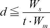
この式より、dのとり得る最大値dhは

なお、端末画面の画素密度は、仕様値として1インチ当たりの画素数を意味するppi(pixel per inch)という単位を慣例的に用いる。そして、この単位を利用すると次の通りとなる。
画素間距離d[mm/pix]に対応するppi値をPとすると、1[inch]=25.4[mm]であることから、
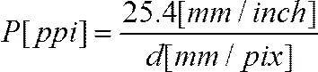
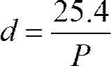


に代入し、不等式を整理すると次の式(A)を得る。

この時、バーコードの1モジュールあたりの構成ドット数t[dot/mod]における画素密度Pがとり得る最小値をPl(t)とすると、

…となる。
ここで、Plをt=1のときのPl(t)の値、すなわち、
ここで、Plをt=1のときのPl(t)の値、すなわち、
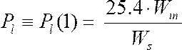
…と置くと、
Pl(t)=t・Pl…と表記することができ、式(A)は次の式(A’)ように表記することができる。
Pl(t)=t・Pl…と表記することができ、式(A)は次の式(A’)ように表記することができる。

これは、表示させたい幅Wmのバーコードが、バーコードスキャナの読取可能幅Wsを超えないための、端末画素密度P[ppi]の条件となる。
この式(A’)から、Plはバーコードのモジュール幅Wmとバーコードスキャナの読取可能幅Wsに依存することが分かる。
次に、第2の条件について考える
端末画面の画素間距離をd[mm/dot]とすると、表示させたいバーコードの最小モジュール幅は、t・d[mm]となる。この値が、バーコードスキャナの最小分解能dsを下回らないことが必要であることから、
t・d≧ds…という関係が必要となる。
端末画面の画素間距離をd[mm/dot]とすると、表示させたいバーコードの最小モジュール幅は、t・d[mm]となる。この値が、バーコードスキャナの最小分解能dsを下回らないことが必要であることから、
t・d≧ds…という関係が必要となる。
この式を第1の条件について考えたときと同様に、ppi値に変換し、


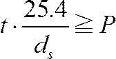
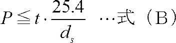
この時、1モジュールあたりの構成ドット数t[dot/mod]における画素密度Pのとり得る最大値をPh(t)とすると、



これがすなわち、バーコードスキャナの最小分解能ds[mm]を下回らない端末画素密度P[ppi]の条件となる。
この式(B’)から、Phはバーコードスキャナの最小分解能dsにのみ依存することが分かる。
この式(B’)から、Phはバーコードスキャナの最小分解能dsにのみ依存することが分かる。
以上、第1の条件及び第2の条件について考えた。結果、第1の条件について考えることにより導かれた式(A’)、第2の条件について考えることにより導かれた式(B’)は下記のとおりである。


この式(A’)及び式(B’)の二つの式から、t・Pl≦P≦t・Phという関係式が成立することが、「Pが『適正範囲』に入る条件」となる。
ここで、上記、式(A’)と式(B’)の関係式がPについて成立せず、「Pが『適正範囲』とならない条件」、すなわち、Pl>Phの関係となる場合を考える。


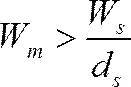
この関係式は、表示すべきバーコードのモジュール幅Wm[mod]が、

を超えると、端末の画面仕様によらず、端末の画面上に表示されるバーコードは、バーコードスキャナで読み取りができないことを示している。また、その「不適となる条件」は、バーコードスキャナの仕様値のみに依存していることを意味する。そのため、この条件を考慮することにより端末の画面仕様を比較することなく、バーコードが「不適」と判定することができる。
また、上記関係式の逆の関係式の、
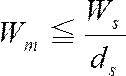
更に、
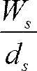
は、バーコードスキャナの最小分解能dsと同じモジュール幅で、バーコードスキャナの読取可能最大幅Wsいっぱいにバーコードを構成した場合のバーコードのモジュール幅、と解釈することができる。
Wmが

を超えている場合に、バーコードの最小モジュール幅が、バーコードスキャナの最小分解能dsより大きくなるように、バーコードを端末画面に表示すると、端末画面上に表示されたバーコードの全体幅がバーコードスキャナの読取可能幅Wsを超える。そのため、バーコードスキャナでの読み取りができなくなる。また、そうするのではなく、Wmが

を超えている場合に、バーコードの幅をバーコードスキャナの読取可能幅Ws以下で表示できるように端末画面に表示すると、表示されたバーコードの最小モジュール幅がバーコードスキャナの最小分解能dsを下回る。そのため、バーコードスキャナでの読み取りができなくなる。つまり、どのような端末画面仕様でも、バーコードスキャナで読み取りができないバーコードとなる。
これは、バーコードスキャナの仕様に対してバーコードのモジュール幅Wmが大きすぎることを意味する。この場合、バーコード作成者は、データを構成するエンコード桁数を削減する、あるいはモジュール幅を小さく構成できるバーコード種別に変更するといった対応が必要となる。また、エンコード桁数の削減やバーコード種別の変更を行なわないのであれば、使用を想定するバーコードスキャナを、より

が大きい値となる機種へ変更する、という対応が必要となる。なお、これらの対応を組み合わせるようにしてもよい。例えば、データを構成するエンコード桁数を削減したりバーコード種別を変更した上で、更に、バーコードスキャナを変更するようにしてもよい。
また、

となるWmはバーコードを構成する上での、バーコードの全体モジュール幅の限界である。
例えば、バーコードスキャナの仕様が、読取可能幅Ws=60[mm]、最小分解能ds=0.15[mm]とすれば、モジュール幅Wmの限界値は、60/0.15=400[mod]となる。従って、全体モジュール幅が400[mod]を超えるバーコードは、表示する端末の画面仕様によらず、「バーコードスキャナで読み取りができない」ものとなる。なぜならば、端末の画面上に表示されるバーコードの幅がバーコードスキャナの読取可能最大幅を超えるか、バーコードを構成する最小モジュール幅がバーコードスキャナの最小分解能を下回ることとなるからである。
以上まとめると、端末画面上に表示させるバーコードの構成を設計する場合は、バーコードのモジュール幅Wmを、この限界値を超えないように、バーコードのコード種別や、エンコード桁数等を決める必要がある。
最後に、第3の条件について考える。
表示するバーコードのモジュール幅Wm(又はtWm)が、表示する端末の画面の幅に収まるとは、表示するバーコードの幅tWm[dot]が端末画面の幅W[pix]を超えないということで、すなわち、端末画面上にバーコード画像をはみ出さずに表示できる、という意味である。
つまり、端末の画面幅W[pix]に対して、
t・Wm≦W → W≧t・Wm…式(C)…の関係となることが第3の条件となる。
t・Wm≦W → W≧t・Wm…式(C)…の関係となることが第3の条件となる。
以上第1の条件、第2の条件及び第3の条件について説明した。
次に、横軸をP[ppi]、縦軸をW[dot]としたP-W図である図1を参照して、前述した第1の条件、第2の条件及び第3の条件を満たすP-W領域、すなわち、式(A’)、式(B’)、式(C)を満たすP-W領域について説明する。
図1に表される101の領域はt=1[dot/mod]の条件下でバーコードを構成した場合に、表示するバーコードの幅とバーコードスキャナの仕様範囲を同時に満たす領域である「適正領域」に相当する。具体的には、表示させたいバーコードのモジュール幅Wmがバーコードスキャナの読取可能幅Wsを超えない最小の画素密度Pl[ppi]と、バーコードスキャナの最小分解能ds[mm]を下回らない最大の端末画面画素密度Ph[ppi]に挟まれ、且つ、端末の画面幅Wが表示させたいバーコードのモジュール幅Wm以上である範囲を示している。
同様に、図1の102の領域はt=2[dot/mod]の条件下でバーコードを構成した場合の「適正領域」を示しており、図1の103の領域はt=3[dot/mod]の条件下でバーコードを構成した場合の「適正領域」を示している。
図1のP-W図に、任意の端末kの画面仕様である、画面幅Wk[pix]と、画面のppi値Pk[ppi]をプロットする。すなわち、k=(Pk,Wk)をプロットする。
そして、このようにプロットしたときに、図1の101の領域、102の領域及び103の領域の内側にk=(Pk,Wk)があれば、端末kは「適正領域」にあり、端末kでバーコードを表示でき、且つ、想定するバーコードスキャナの仕様で読み取りができることが示される。
一方で、このようにプロットしたときに、図1の101の領域、102の領域及び103の領域の外側の領域にk=(Pk,Wk)があれば、端末kは「適正領域」に無く、端末kでバーコードを表示できない、あるいは、表示できたとしても想定するバーコードスキャナの仕様で読み取りができない可能性が高い、と判断することができる。
また、端末kの画面仕様k=(Pk,Wk)が、前述の「適正領域」の内側にある場合、端末kの画面上に表示すべきバーコードの条件は、「適正領域」が定義するtの条件に従う必要があることを意味する。例えば、端末kが前述の「適正領域」の1つである101の領域にあるのであれば、t=1とする必要がある。
また、任意の端末kの画面仕様k(Pk,Wk)が前述の「適正領域」に無い場合には、この任意の端末kが単に適正ではないということが分かるだけではない。P-W図上にプロットしたk(Pk,Wk)の位置に基づいて、適正でない要因、すなわち、不適正要因も分かる。
この点について、図1を単純化した図である、図2-1を参照して説明する。
図2-1は図1のt=1の条件での「適正領域」及び「適正ではない領域」のみを示したものである。図2-1の201の領域は前述の図1の101に相当し、「適正領域」を示している。一方で、図2-1の201の領域以外の202の領域、203の領域及び204の領域は、t=1の条件下では、「適正ではない領域」ということになる。それぞれの「適正ではない領域」に任意の端末kの画面仕様k(Pk,Wk)がプロットされる場合の不適正要因は、それぞれ次のとおりである。
<図2-1の202の領域、すなわち、Wk<Wmの領域の不適正要因>
端末の画面幅Wkがt=1[dot/mod]の条件でも、表示させるべきバーコードのモジュール幅Wmを下回るため、端末の画面上に目的のバーコードを表示できない。
端末の画面幅Wkがt=1[dot/mod]の条件でも、表示させるべきバーコードのモジュール幅Wmを下回るため、端末の画面上に目的のバーコードを表示できない。
<図2-1の203の領域、すなわち、Pk<Plかつ、Wk≧Wmの領域の不適正要因>
端末の画面上にt=1[dot/mod]の条件でバーコードを表示することはできる。しかしながら、画素密度が低く(画素間距離が大きく)、表示させたバーコードの幅がバーコードスキャナの読取可能幅Wsを超えてしまい、想定したバーコードスキャナの仕様では読み取りできない。
端末の画面上にt=1[dot/mod]の条件でバーコードを表示することはできる。しかしながら、画素密度が低く(画素間距離が大きく)、表示させたバーコードの幅がバーコードスキャナの読取可能幅Wsを超えてしまい、想定したバーコードスキャナの仕様では読み取りできない。
<図2-1の204の領域、すなわち、Pk>Phかつ、Wk≧Wmの領域の不適正要因>
端末の画面上にt=1[dot/mod]の条件でバーコードを表示することはできる。しかしながら、画素密度が高く(画素間距離が小さく)、表示させたバーコードの最小モジュール幅がバーコードスキャナの最小分解能dsを下回り、想定したバーコードスキャナの仕様では読み取りできない。
端末の画面上にt=1[dot/mod]の条件でバーコードを表示することはできる。しかしながら、画素密度が高く(画素間距離が小さく)、表示させたバーコードの最小モジュール幅がバーコードスキャナの最小分解能dsを下回り、想定したバーコードスキャナの仕様では読み取りできない。
以上、図2-1を参照して説明した「適正でない領域」の場所による「不適正要因の違い」を踏まえ、t=1~3の適正領域を定義した図1の「適正でない領域」の「不適正要因」について図2-2を参照して説明する。
図2-2の211の領域、212の領域及び213の領域は、「適正領域」である図1の101の領域、102の領域及び103の領域に相当する。
このとき、「適正でない領域」は214の領域乃至221の領域に分類され、それぞれの領域は次のような「不適正要因」を有する。
<図2-2の214の領域、すなわち、Wk<Wmの領域の不適正要因>
端末の画面幅Wkがt=1[dot/mod]の条件下でも、表示させるべきバーコードのモジュール幅Wmを下回っているため、バーコードを表示できない。
端末の画面幅Wkがt=1[dot/mod]の条件下でも、表示させるべきバーコードのモジュール幅Wmを下回っているため、バーコードを表示できない。
<図2-2の215の領域、すなわち、Wk≧WmかつPk<Plの領域の不適正要因>
端末の画面上にt=1[dot/mod]の条件下でバーコードを表示することはできる。しかしながら、画素密度が低く(画素間距離が大きく)、表示させたバーコードの幅がバーコードスキャナの読取可能幅Wsを超えてしまい、バーコードスキャナで読取できない。
端末の画面上にt=1[dot/mod]の条件下でバーコードを表示することはできる。しかしながら、画素密度が低く(画素間距離が大きく)、表示させたバーコードの幅がバーコードスキャナの読取可能幅Wsを超えてしまい、バーコードスキャナで読取できない。
<図2-2の216の領域、すなわち、Wm≦Wk<2Wmかつ、Pk>Phの領域の不適正要因>
端末の画面上にt=1[dot/mod]の条件下でバーコードを表示することはできる。しかしながら、画素密度が高く(画素間距離が小さく)、表示させたバーコードの最小モジュール幅がバーコードスキャナの最小分解能dsを下回り、バーコードスキャナで読取できない。
端末の画面上にt=1[dot/mod]の条件下でバーコードを表示することはできる。しかしながら、画素密度が高く(画素間距離が小さく)、表示させたバーコードの最小モジュール幅がバーコードスキャナの最小分解能dsを下回り、バーコードスキャナで読取できない。
<図2-2の217の領域、すなわち、2Wm≦Wk<3Wmかつ、Ph<Pk<2Plの領域の不適正要因>
端末の画面上にt=1[dot/mod]及びt=2[dot/mod]の条件下でバーコードを表示することはできる。しかしながら、t=2で表示した場合は、バーコードシンボルの幅がバーコードスキャナの読取可能幅Wsを超えてしまい、また、t=1で表示した場合は、バーコードの最小モジュール幅がバーコードスキャナの最小分解能dsを下回り、何れの場合であってもバーコードスキャナで読取できない。
端末の画面上にt=1[dot/mod]及びt=2[dot/mod]の条件下でバーコードを表示することはできる。しかしながら、t=2で表示した場合は、バーコードシンボルの幅がバーコードスキャナの読取可能幅Wsを超えてしまい、また、t=1で表示した場合は、バーコードの最小モジュール幅がバーコードスキャナの最小分解能dsを下回り、何れの場合であってもバーコードスキャナで読取できない。
<図2-2の218の領域、すなわち、2Wm≦Wk<3Wmかつ、Pk>2Phの領域の不適正要因>
端末の画面上にt=1[dot/mod]及びt=2[dot/mod]の条件下でバーコードを表示することはできる。しかしながら、何れのtの条件下でも、バーコードの最小モジュール幅がバーコードスキャナの最小分解能dsを下回り、バーコードスキャナで読取できない。
端末の画面上にt=1[dot/mod]及びt=2[dot/mod]の条件下でバーコードを表示することはできる。しかしながら、何れのtの条件下でも、バーコードの最小モジュール幅がバーコードスキャナの最小分解能dsを下回り、バーコードスキャナで読取できない。
<図2-2の219の領域、すなわち、3Wm≦Wk<4Wmかつ、Ph<Pk<2Plの領域の不適正要因>(4Wmは図示を省略する)
端末の画面上にt=1[dot/mod]、t=2[dot/mod]及びt=3[dot/mod]の何れの条件下であってもバーコードを表示することはできる。しかしながら、t=2又は3で表示した場合は、バーコードの幅がバーコードスキャナの読取可能幅Wsを超えてしまい、また、t=1で表示した場合は、バーコードの最小モジュール幅がバーコードスキャナの最小分解能dsを下回り、何れの場合であってもバーコードスキャナで読取できない。
端末の画面上にt=1[dot/mod]、t=2[dot/mod]及びt=3[dot/mod]の何れの条件下であってもバーコードを表示することはできる。しかしながら、t=2又は3で表示した場合は、バーコードの幅がバーコードスキャナの読取可能幅Wsを超えてしまい、また、t=1で表示した場合は、バーコードの最小モジュール幅がバーコードスキャナの最小分解能dsを下回り、何れの場合であってもバーコードスキャナで読取できない。
<図2-2の220の領域、すなわち、3Wm≦Wk<4Wmかつ、2Ph<Pk<3Plの領域の不適正要因>(4Wmは図示を省略する)
端末の画面上にt=1[dot/mod]、t=2[dot/mod]及びt=3[dot/mod]の何れの条件下であってもバーコードを表示することはできる。しかしながら、t=3で表示した場合は、バーコードの幅がバーコードスキャナの読取可能幅Wsを超えてしまい、また、t=1又は2で表示した場合は、バーコードの最小モジュール幅がバーコードスキャナの最小分解能dsを下回り、何れの場合であってもバーコードスキャナで読取できない。
端末の画面上にt=1[dot/mod]、t=2[dot/mod]及びt=3[dot/mod]の何れの条件下であってもバーコードを表示することはできる。しかしながら、t=3で表示した場合は、バーコードの幅がバーコードスキャナの読取可能幅Wsを超えてしまい、また、t=1又は2で表示した場合は、バーコードの最小モジュール幅がバーコードスキャナの最小分解能dsを下回り、何れの場合であってもバーコードスキャナで読取できない。
<図2-2の221の領域、すなわち、3Wm≦Wk<4Wmかつ、Pk>3Phの領域の不適正要因>(4Wmは図示を省略する)
端末の画面上にt=1[dot/mod]、t=2[dot/mod]及びt=3[dot/mod]の何れの条件下であってもバーコードを表示することはできる。しかしながら、何れのtの条件下でも、バーコードの最小モジュール幅がバーコードスキャナの最小分解能dsを下回り、バーコードスキャナで読取できない。
端末の画面上にt=1[dot/mod]、t=2[dot/mod]及びt=3[dot/mod]の何れの条件下であってもバーコードを表示することはできる。しかしながら、何れのtの条件下でも、バーコードの最小モジュール幅がバーコードスキャナの最小分解能dsを下回り、バーコードスキャナで読取できない。
次に、再度図1を参照して、二つの端末(端末k1及び端末k2)について考える。
端末k1の画面の仕様に対応する点である図1の104は、前述の「適正領域」の一つに入っている。つまり、端末k1は「適正領域」に入る端末の例である。この端末k1は、t=2[dot/mod]の構成であれば、表示したいバーコードを画面上に表示でき、また、バーコードスキャナの読取可能幅及び最小分解能の仕様範囲で読取できる、という範囲内にあることが分かる。
端末k2の画面の仕様に対応する点である図1の105は、前述の「適正領域」の一つに入っていない。つまり、端末k1は「適正領域」に入らない端末の例である。この端末k2の縦軸方向はWm<Wk2<2Wm、横位置が2Ph<Pk2<3Plの位置である。そのため、図2-2の216の領域に相当し、t=1[dot/mod]の構成であれば、表示したいバーコードを画面上に表示することができる。しかしながら、表示されるバーコードの最小モジュール幅がバーコードスキャナの最小分解能の仕様値を下回り、使用を想定するバーコードスキャナの仕様では、読み取りできないことが分かる。
次に、「適正率」の算出について説明する。
前述の「適正領域」をU、n種類の端末k1、k2…knの点集合をkとする。また、適正領域Uの範囲内にある端末kの数、すなわち、k∈Uとなる端末の数をmとする。すると、端末の適正率zをz=m/n(0≦z≦1)とすることができる。これにより、使用したいバーコードの構成仕様、バーコードスキャナの仕様、端末の画面仕様をそれぞれ考慮した「適正率」を算出することができる。
以上により、「『使用したいバーコード』が適切かどうか」という課題に対し、定量的な「適正率」の値そのものを算出することができる。また、算出した「適正率」を、他の条件下で算出された他の「適正率」の値と比較することによって「評価」を行なうことが可能となる。
以上説明した各変数及び各式等についてまとめると以下のようになる。
<条件から導かれる式>


W≧t・Wm …式(C)

式(D)は式(A’)及び式(B’)の双方が成立するために必要なWmの範囲を示す式である。式(A’)及び式(B’)の説明の際に「不適となる条件」として説明したように
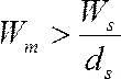
の場合にPl>Phの関係となり、式(A’)、式(B’)が成立しなくなる。そのため、式(A’)、式(B’)の双方が成立するためにはモジュール幅Wmが上記式(D)の範囲にあることが前提となる。
<使用する変数一覧(単位は一般的に想定されるものを使用している)>
[定義]
Wm:表示させたいバーコードの横モジュール幅であり、単位は[mod]とする。また、Wmは、正の整数である。
t:バーコード画像の1モジュールあたりの構成ドット数であり、単位は[dot/mod]とする。tは、正の整数である。
Ws:バーコードスキャナの読取可能なバーコードの幅の上限であり、単位は[mm]とする。Wsは、正の数である。
ds:バーコードスキャナの最小分解能であり、単位は[mm]とする。dsは、正の数である。
[定義]
Wm:表示させたいバーコードの横モジュール幅であり、単位は[mod]とする。また、Wmは、正の整数である。
t:バーコード画像の1モジュールあたりの構成ドット数であり、単位は[dot/mod]とする。tは、正の整数である。
Ws:バーコードスキャナの読取可能なバーコードの幅の上限であり、単位は[mm]とする。Wsは、正の数である。
ds:バーコードスキャナの最小分解能であり、単位は[mm]とする。dsは、正の数である。
[算出値]

:表示させたいバーコード幅t・Wmがバーコードスキャナの読取可能幅Wsを超えない最大の画素間距離[mm/dot]。

:dh[mm/dot]に対応する最小のppi値[ppi]。→表示させたいバーコード幅t・Wmがバーコードスキャナの読取可能幅Wsを超えない最小の画素密度[ppi]。
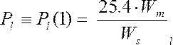
とし、次のように式を記述する。


:バーコードスキャナの最小分解ds[mm]を下回らない最大の端末画面ppi値[ppi]。
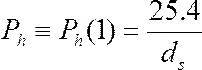

[その他]
d:(任意の)端末の画素間距離[mm/pix]。
d:(任意の)端末の画素間距離[mm/pix]。

:(任意の)端末画面の画素間距離d[mm/pix]を[ppi]に変換。
W:(任意の)端末の画面幅[pix]。
W:(任意の)端末の画面幅[pix]。
なお、これらを説明する図は、特に図1、図2-1及び図2-2である。また、本評価方法に特に関連する式は、式(A)’、式(B)’、式(C)、式(D)である。
次に、本発明の実施例について図を参照して具体的に説明する。以下の説明では、5つの実施例について詳細に説明するが、まずこれら5つの実施例について簡略に説明する。
まず、実施例1は、画像表示装置及びバーコード読取装置を評価するための評価装置に関する実施例である。
また、実施例2は、複数の画像表示装置及び複数のバーコード読取装置を評価するための評価装置に関する実施例である。
更に、実施例3は、複数の画像表示装置で表示可能であって特定のバーコード読取装置で読み取り可能なバーコードを決定する評価装置に関する実施例である。
実施例4は、複数の画像表示装置で表示可能である特定のバーコードを読み取るバーコード読取装置の仕様を決定するバーコード読取装置の仕様決定装置に関する実施例である。
実施例5は、画像表示装置に表示するバーコード画像を生成するバーコード画像生成システムに関する実施例である。
実施例1について詳細に説明する。実施例1は、使用したいバーコードが、表示したい端末で表示でき、且つ、使用を想定するバーコードスキャナで読み取り可能か否かを判定する評価装置に関するものである。なお、以下の各実施例における、バーコードは本発明の「バーコード画像」に相当する。また、端末は、本願発明の「画像表示装置」に相当する。更に、バーコードスキャナは本発明の「バーコード読取装置」に相当する。更に、評価装置は、本願発明の「バーコード評価装置」に相当する。
まず、図3を参照して、かかる評価装置の構成例について説明する。図3を参照すると評価装置の一構成例である評価装置10は、CPU(Central Processing Unit)11、記憶装置群12、画像出力部13及びI/O(Input/Output)14を含む。また、これら評価装置10に含まれる各部は、評価装置10内に設けられたバスライン15を介して相互に通信可能に接続される。
更に、画像出力部13には、表示装置21が接続される。更に、I/O14には、入力装置22が接続される。
CPU11は、記憶装置群12に格納されたプログラムに基づいた演算処理を行い、演算結果に基づいて評価装置10全体を制御する。また、CPU11は、同様にして、使用したいバーコードが、表示したい端末で表示でき、且つ、使用を想定するバーコードスキャナで読み取り可能か否かを判定する。
記憶装置群には、各種の記憶装置が含まれる。例えば、RAM(Random Access Memory
)といった主記憶装置や、ROM(Read Only Memory)や、HDD(Hard disk drive)あるいはSSD(Solid State Drive)といった補助記憶装置が含まれる。これらの記憶装置は、変数や、プログラムや、その他表示に必要な情報等を記憶する。
)といった主記憶装置や、ROM(Read Only Memory)や、HDD(Hard disk drive)あるいはSSD(Solid State Drive)といった補助記憶装置が含まれる。これらの記憶装置は、変数や、プログラムや、その他表示に必要な情報等を記憶する。
画像出力部13は、CPU11の指示に従って画像を出力する部分である。画像出力部13が出力した画像信号は表示装置21に出力される。
表示装置21は、使用したいバーコードが、表示したい端末で表示でき、且つ、使用を想定するバーコードスキャナで読み取り可能か否の判定結果を、ユーザに参照させるための装置である。表示装置21は、例えば、液晶ディスプレイにより実現される。
また、I/O14は、評価装置10に外部機器を接続するための部分である。I/O14には例えば入力装置22が接続される。
入力装置22は、ユーザの入力を受け付ける装置であり、例えばキーボードにより実現される。ユーザが、入力装置22を利用して例えば、バーコードの幅、バーコードスキャナの仕様、端末の画面仕様といった情報を入力する。すると、入力された情報は、I/O14を介して評価装置10入力される。そして、これらの情報は、CPU11により処理される。
なお、評価装置10は、本実施例特有の装置として実現されても良いが、汎用の、例えばパーソナルコンピュータ等の装置に、本実施例特有のプログラムを組み込むことにより実現してもよい。
次に、或るバーコードが、或る端末で表示可能で、且つ、或るバーコードスキャナで読み取り可能か否かを判定する際の、評価装置10の処理について、図4のフローチャートを参照して説明する。
まず、ステップS401、ステップS402及びステップS403で、バーコードの幅、バーコードスキャナの仕様、及び端末の画面仕様、といった評価のために必要な情報の入力を受け付ける。
具体的には、ユーザが入力装置22等の装置を用いて必要な情報を入力する。そして、評価装置10は、この必要な情報をI/O14を介して受け付ける。なお、評価装置10に、ネットワークを介したデータ通信を行なうための通信部を更に含ませるようにしても良い。そして、必要な情報の一部又は全部を、通信部を介したデータ通信により、外部の装置から取得するようにしても良い。
具体的に、ステップS401では、使用したいバーコードを識別するための情報(例えば、使用したいバーコードの名称)と、このバーコードの、バーコードシンボルとバーコードの左右余白とを含む全体モジュール幅Wm[mod]の入力を受け付ける。
ステップS402では、使用を想定するバーコードスキャナを識別するための情報(例えば、使用を想定するバーコードスキャナの名称)と、このバーコードスキャナの最小分解能ds[mm]及びこのバーコードスキャナの読取可能最大幅Ws[mm]の入力を受け付ける。
ステップS403では、使用を想定する端末を識別するための情報(例えば、使用を想定する端末の名称)と、この端末の画面仕様である、画面幅(ピクセル数)Wk[pix]及び画素密度Pk[ppi]の入力を受け付ける。
ここで、使用したいバーコードのモジュール幅Wmは、使用したいバーコードのコード種別やエンコードする情報桁数等の、「使用したいバーコード」の構成条件に依存する。そのため、使用したバーコードの種類やエンコードする情報桁数等が予め決定されているならば、使用したいバーコードのモジュール幅Wmを事前に算出することができる。
ここで、コード種別やエンコードする情報桁数等の、「使用したいバーコード」の構成条件に応じたモジュール幅Wmの計算式の例を表1に示す。

なお、ステップS401では、ユーザからモジュール幅Wmそのものを受け付けても良い。つまり、ユーザが、コード種別やエンコードする情報桁数等の、「使用したいバーコード」の構成条件に基づいて予め算出したモジュール幅Wmを受け付けても良い。
しかし、そうするのではなく、ユーザからモジュール幅Wmの算出に必要な、コード種別やエンコードする情報桁数等の、「使用したいバーコード」の構成条件等の情報を受け付け、評価装置10がモジュール幅Wmを算出するようにしても良い。
その場合は、評価装置10に、表1に示した計算式に基づいた算出を行なうための機能を実装する。そのためには、例えば、表1に示した計算式に基づいた算出を行なうためのプログラムを記憶装置群12に格納しておく。そして、CPU11が、このプログラムに基づいた演算を行なうことによりモジュール幅Wmを算出する。
モジュール幅Wmの算出に必要な情報は、例えばステップS401の段階でユーザが入力する、コードの種類、データの桁数、及びその他コードに依存した必要な情報(例えば、CODABARのNW比等)を受け付ける。そして、これらの情報に基づいてモジュール幅Wmを算出して得れば良い。
次に、ステップS401、ステップS402及びステップS403で受け付けた情報に基づいて、バーコードの適否判定処理を開始する(ステップS404)。
ここで、ステップS404では、端末の画面仕様については考慮せず、バーコード寸法がバーコードスキャナの仕様に対して適切か否かをまず判断する。
具体的には、バーコードスキャナの読取可能幅Ws[mm]と同じ幅のバーコードが、バーコードスキャナの最小分解能ds[mm]を最小モジュール幅として構成した場合のモジュール幅、すなわち、
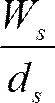
が、ステップS401で入力したバーコードの幅Wm[mod]以上かどうか、すなわち、
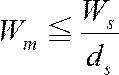

の関係が成立していない場合は(ステップS404においてNo)、ステップS405に進む。
ここで、
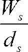
とは、バーコードスキャナで読取可能なバーコードの最大幅(モジュール幅)である。式(A’)及び式(B’)の説明の際に前述したように、理論上、

を超えるモジュール幅をもつバーコードシンボルは、端末の画面に表示できたとしても、バーコードの全体幅がバーコードスキャナの読取可能幅を超えるか、バーコードスキャナの最小分解能を下回ることになり、バーコードスキャナで読み取りできない。
例えば、或るバーコードスキャナの読取可能幅Ws=60[mm]、最小分解能ds=0.15[mm]とすれば、
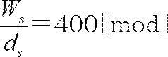
となり、モジュール幅Wmが400[mod]を超えるバーコードは、表示する端末の画面仕様を考慮するまでもなく、この或るバーコードスキャナでは読み取りできない、ということになる。
ステップS405では、「バーコード寸法がバーコードスキャナ仕様に不適合」である旨を表示装置21に出力し、ステップS412に進んでNG判定となり、ステップS413で一連の判定処理を終了する。
一方、ステップS404の判定で
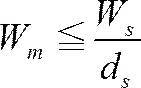
の関係が成立していれば(ステップS404においてYes)、ステップS406に進む。
ステップS406では、ステップS401で入力されたモジュール幅Wmを持つバーコードが、ステップS403で入力された画面仕様を持つ端末の画面に表示可能であるか否かを判断する。具体的には、バーコードのモジュール幅Wmが端末画面幅Wk以下であれば、バーコードは端末に「表示可能」であり、そうでなければ「表示不能」、となる。
ステップS406の判定で「表示不能」であれば(ステップS406においてNo)、ステップS407に進む。
そして、ステップS407では「バーコードは端末画面上に表示不能」である旨を表示装置21に出力し、ステップS412に進んでNG判定となり、ステップS413で一連の判定処理を終了する。
一方、406の判定で「バーコードは端末画面上に表示可能」であれば(ステップS406においてYes)、ステップS408に進む。
ステップS408では、モジュール幅Wmのバーコードを、端末画面上に表示した場合、バーコードの最小モジュール幅がバーコードスキャナの最小分解能より大きく、且つ、端末画面上に表示したときのバーコードの幅[mm]がバーコードスキャナの読取可能幅以下であるか否かを判定する。
具体的には、次のように計算する。
表示するバーコードの最小モジュール幅をt[dot/mod]とすると、

となる整数を最大値として、1[dot/mod]、2[dot/mod]…、となる。
このとき、tのとり得る範囲で、端末の画素密度Pkに対し
このとき、tのとり得る範囲で、端末の画素密度Pkに対し


…の二式が同時に成立するtが存在するか否かを判定する。判定の結果、二式が同時に成立するtが一つも存在しなければ「読取不能」となり(ステップS408においてNo)、ステップS409に進む。そして、ステップS409では、「バーコードは表示可能だが、バーコードスキャナで読取不能」である旨を表示装置21に出力し、ステップS412に進みNG判定となり、ステップS413で一連の判定処理を終了する。
一方で、式(A’)、式(B’)が同時に成立するtが一つでも存在すれば、「読取可能」となり(ステップS408においてYes)、ステップS410に進む。ステップS410では「バーコードは表示可能でバーコードスキャナで読取可能」である旨を表示装置21に出力する。なお、この場合に、式(A’)、式(B’)が同時に成立するtの値がいくつであるのかも表示するようにしても良い。そして、ステップS411に進み、OK判定となり、ステップS413で一連の判定処理を終了する。
ステップS413で一連の判定処理終了後、図5の様に、縦軸を端末画面幅W[pix]、横軸を画素密度P[ppi]としたP-W平面に、式(A’)、式(B’)及びW≧t・Wmの全てが同時に成立する領域を表す。本例では、これら全てが同時に成立する領域として501の領域及び502の領域を示す。
そして、そのP-W平面上に、判定処理の対象とした端末の、画素密度Pk[ppi]及び画面幅Wk[pix]に対応する点、すなわち、判定処理の対象とした端末の画面仕様に対応する点をプロットする。
そして、式(A’)、式(B’)及びW≧t・Wmの全てが同時に成立する領域を示すと共に、判定処理の対象とした端末の画面仕様に対応する点をプロットした、かかるP-W平面を表示装置21に表示する等の方法で出力する。
例えば、図5に示されるように、判定処理の対象とした端末の画面仕様に対応する点である503をプロットした図を表示する。このようにすることで、幅Wm[mod]のバーコードを、画素密度Pk[ppi]、画面幅Wk[pix]の端末画上に表示しようとしたときに表示でき、且つ、最小分解能ds[mm]と読取可能最大幅Ws[mm]のバーコードスキャナで読取可能となるかどうか、すなわち、バーコード幅、端末画面仕様、バーコードスキャナ仕様の関係が「適正」であるか否かが可視化され、端末の画面を参照したユーザが視覚的に確認することができる。
例えば、ユーザが、図5が表示された表示装置21を参照すると、端末kの画面仕様に対応する点である503が、t=2の条件下であれば「適正領域」にあることが分かる。つまり、端末kについて、t=2の条件下であれば、バーコード幅、端末画面仕様、バーコードスキャナ仕様の関係が「適正」となることが分かる。
また、式(A’)、式(B’)及びW≧t・Wmの全てが同時に成立する領域に端末の画素密度Pk[ppi]、画面幅Wk[pix]の点kが入らない場合は何らかの原因で「適正でない」ことが分かる。更に、式(A’)と式(B’)及びW≧t・Wmがの全て同時に成立する領域と点kの位置関係により、適正でない「原因」と、「どの程度」適正ではないのかも判断することができる。
例えば、図5に示される、端末k1の画面仕様に対応する点である504は、501の領域及び502の領域の何れの領域にも無い。つまり、端末k1の画面仕様は、バーコード幅及びバーコードスキャナ仕様との関係で、「適正でない」ことを意味する。この時、端末k1の画面仕様に対応する点である504の縦軸Wk1はWmと2Wmの間に位置するため、t=1の条件でのみ「表示可能」と分かる。しかし、t=1の場合の適正領域である501の領域より右側、すなわち端末k1の画面仕様に対応する点である504の横軸Pk1はPhより大きい。そのため、t=1の条件で端末にバーコードを端末上に表示した場合、表示されたバーコードの最小モジュール幅がバーコードスキャナの最小分解能を下回るためバーコードスキャナで読み取りできない、という「不適正要因」が分かる。また、端末k1の画面仕様に対応する点である図5の504の例で、504が、どの程度適正領域境界から離れているかを、

で定量化し、不適の「程度」を測ることができる。
また、端末k2の画面仕様に対応する点である図5の505は端末k1の画面仕様に対応する点である504同様、501の領域及び502の領域の何れの領域にも無い。つまり、端末k2の画面仕様は、バーコード幅及びバーコードスキャナ仕様との関係で、「適正でない」ことを意味する。この時、端末k2の画面仕様に対応する点である505の縦軸Wk2はWmと2Wmの間に位置するため、t=1の条件でのみ「表示可能」と分かる。
しかし、t=1の場合の適正領域である501の領域よりより左側、すなわち点k2の横軸Pk2はPlより小さい。そのため、t=1の条件で端末にバーコードを端末上に表示した場合、表示されたバーコードの全体幅がバーコードスキャナの読取可能幅を上回り、バーコードスキャナで読み取りできない、という「不適正要因」が分かる。また、端末k2の画面仕様に対応する点である図5の505の例で、505が、どの程度適正領域境界から離れているかを、

で定量化し、不適の「程度」を測ることができる。
以上説明した本実施例では、バーコード幅、端末画面仕様、バーコードスキャナ仕様の関係が「適正」となるか否かを評価することができる。また、適正でない場合には、適正でない「原因」と、「どの程度」適正ではないのかも分かる。そして、これらの情報を可視化して、ユーザに提示することより、ユーザが視覚的にこれらの情報を把握することが可能となる、という効果を奏する。
次に、実施例2について説明する。実施例2は、使用したい複数のバーコードが、表示したい複数の端末で表示でき、且つ、使用を想定する複数のバーコードスキャナで読み取り可能か否かを判定する評価装置に関するものである。
本実施例は、複数のバーコードと複数のバーコードスキャナ、及び、複数の端末で、端末画面上にバーコードを表示でき、かつバーコードスキャナで読み取りが可能かどうかを総合的に判断する手段として有効である。
本実施例における評価装置10の構成は、図3を参照して説明した実施例1の構成と同様であるため、再度の説明を省略する。
次に、あるバーコードが、ある端末で表示可能で、且つ、あるバーコードスキャナで読み取り可能かどうかを判定する際の評価装置10の処理を、図6のフローチャートを参照して説明する。ここで、図6のフローチャートに示される処理は、図4を参照して説明した実施例1における処理を変形し、複数のバーコード、複数の端末、複数のバーコードスキャナで読み取り可能か否かを判定することができるようにしたものである。
まず、ステップS601、ステップS602及びステップS603で、複数のバーコードの幅、複数のバーコードスキャナの仕様、及び複数の端末の画面仕様、といった評価のために必要な情報の入力を受け付ける。具体的には、ユーザが入力装置22等の装置を用いて必要な情報を入力する。そして、評価装置10は、この必要な情報をI/O14を介して受け付ける。なお、評価装置10に、ネットワークを介したデータ通信を行なうための通信部を更に含ませるようにしても良い。そして、必要な情報の一部又は全部を、通信部を介したデータ通信により、外部の装置から取得するようにしても良い。
より具体的には、ステップS601では、使用したいバーコードを識別するための情報(例えば、使用したいバーコードの名称)、このバーコードの、バーコードシンボルとバーコードの左右余白とを含む全体モジュール幅Wm[mod]の入力を複数のバーコードの分受け付ける。
ステップS602では、使用を想定するバーコードスキャナを識別するための情報(例えば、使用を想定するバーコードスキャナの名称)、このバーコードスキャナの最小分解能ds[mm]とこのバーコードスキャナの読取可能最大幅Ws[mm]の入力をバーコードスキャナ複数台分受け付ける。
ステップS603では、使用を想定する端末を識別するための情報(例えば、使用を想定する端末の名称)と、この端末の画面仕様である、画面幅(ピクセル数)Wk[pix]及び画素密度Pk[ppi]の入力を端末複数台分受け付ける。
入力された情報は、それぞれ所定のデータベースに格納され、記憶される。具体的には、バーコード情報データベース12-1、バーコードスキャナ情報データベース12-2、端末情報データベース12-3に記録される。ここで、これら3つのデータベースは、評価装置10の記憶装置群12に含まれる何れかの記憶装置により実現されるものとする。なお、今回の処理に伴って実行されるステップS601、ステップS602及びステップS603において情報が入力されても良いが、入力されるべき情報の一部又は全部を、予め、バーコード情報データベース12-1、バーコードスキャナ情報データベース12-2、端末情報データベース12-3に記録しておくようにしても良い。
ここで、入力される情報とデータベースとの対応について説明する。
バーコード情報データベース12-1には、ステップS601にて入力されるバーコード情報、すなわち、使用したいバーコードを識別するための情報(例えば、使用したいバーコードの名称)、このバーコードの、バーコードシンボルとバーコードの左右余白とを含む全体モジュール幅Wm[mod]、といった情報が複数のバーコード分格納される。ここで、使用したいバーコードのモジュール幅Wmは、実施例1と同様、使用するバーコードの種類やエンコードする情報桁数等、「使用したいバーコード」の構成条件に依存し、事前に算出することができる。また、実施例1同様に、評価装置10が、表1に示した計算式等に基づいてモジュール幅Wmを算出するようにしてもよい。
また、バーコードスキャナ情報データベース12-2には、ステップS602にて入力されるバーコードスキャナ情報、すなわち、使用を想定するバーコードスキャナを識別するための情報(例えば、使用を想定するバーコードスキャナの名称)、このバーコードスキャナの最小分解能ds[mm]とこのバーコードスキャナの読取可能最大幅Ws[mm]、といった情報がバーコードスキャナ複数台分格納される。
また、端末情報データベース12-3には、ステップS603にて入力される端末情報、すなわち、使用を想定する端末を識別するための情報(例えば、使用を想定する端末の名称)と、この端末の画面仕様である、画面幅(ピクセル数)Wk[pix]及び画素密度Pk[ppi]といった情報が端末複数台分格納される。
このとき、バーコード情報データベース12-1、バーコードスキャナ情報データベース12-2、端末情報データベース12-3の各データベース上では、それぞれのデータをn番目のデータとして取り扱う。また、評価装置10のCPU11は、必要に応じてn番目のデータを取り出すことができるものとする。バーコード情報データベース12-1、バーコードスキャナ情報データベース12-2、端末情報データベース12-3の各データベースの記録状態の例を、表2、表3及び表4として以下に示す。

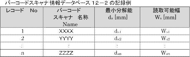

これら各データベースに情報が格納されたのち、図6のステップS604から適否判定処理に入るので、この処理について説明を行なう。
ステップS604ではバーコード情報データベース12-1から、未判定のバーコード幅情報Wm[mod]を取り出す。次に、ステップS605で、未判定のバーコードスキャナ仕様である、バーコードスキャナの最小分解能ds[mm]と読取可能最大幅Ws[mm]を取り出す。次に、606で、バーコードスキャナ情報データベース12-2から未判定の端末の画面仕様である、画面幅(ピクセル数)Wk[pix]と画素密度Pk[ppi]を取り出す。このように、本実施例では、判定処理のたびに未判定の情報を取り出して、判定対象を変更することにより、複数のバーコード、複数のバーコードスキャナ仕様、及び複数の端末の画面仕様の、各組み合わせについて判定を行なう。
次に、ステップS607に進み、端末の画面仕様によらず、バーコード寸法がバーコードスキャナの仕様に対して適切かどうかを判断する。
具体的な判定方法は、実施例1の図4のステップS404の判定方法と同様、

が、ステップS604で取り出したバーコードの幅Wm[mod]より大きいかどうか、以上かどうか、すなわち、


の関係が成立していない場合は(ステップS607においてNo)、ステップS608に進む。
ステップS608では、端末画面仕様を問わず「バーコード寸法がバーコードスキャナ仕様に不適合」と判断し、ステップS616に進んでNG判定とする。そして、ステップS619で、端末仕様の個別確認処理をすることなく、今回判定の対象としている、モジュール幅Wmを持つバーコードが、全ての端末でNGという判定結果を判定結果データベース12-4に記録する。更に、全ての端末の判定が終了した、という扱いにしたうえで、次の処理であるステップS620に進む。ここで、判定結果データベース12-4は、判定結果を記憶するデータベースである。また、判定結果データベース12-4は、バーコード情報データベース12-1、バーコードスキャナ情報データベース12-2、及び端末情報データベース12-3の3つのデータベースと同様に、評価装置10の記憶装置群12に含まれる何れかの記憶装置により実現されるものとする。
一方、ステップS607の判定で

の関係が成立していれば(ステップS607においてYes)、ステップS609に進む。
ステップS609では、実施例1の図4のステップS406と同様、ステップS604で入力され、今回判定の対象としている、モジュール幅Wmを持つバーコードが、ステップS606で入力され、今回判定の対象としている、画面仕様を持つ端末の画面に表示可能であるか否かを判断する。具体的には、バーコードのモジュール幅Wmが端末画面幅Wk以下であれば、バーコードは端末に「表示可能」であり、そうでなければ「表示不能」、となる。
ステップS609の判定で「表示不能」であれば(ステップS609においてNo)、ステップS610に進む。
ステップS610では「バーコードは端末画面上に表示不能」と判断し、ステップS615に進んでNG判定とする。そして、ステップS617では、判定した端末の情報、バーコードのモジュール幅情報、バーコードスキャナの仕様情報と判定結果を判定結果データベース12-4に記録し、次の処理であるステップS618に進む。
一方、ステップS609の判定で「バーコードは端末画面上に表示可能」であれば(ステップS609においてYes)、ステップS611に進む。
ステップS611では、実施例1の図4のステップS408と同様、今回判定の対象としているモジュール幅Wmのバーコードを今回判定の対象としている端末画面上に表示した場合、バーコードの最小モジュール幅が今回判定の対象としているバーコードスキャナの最小分解能より大きく、且つ、端末画面上に表示したときのバーコードの幅が今回判定の対象としているバーコードスキャナの読取可能Ws[mm]幅以下であるか否かを判定する。
具体的には、実施例1と同様に、次のように計算する。
表示するバーコードの最小モジュール幅をt[dot/mod]とすると、
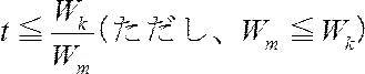
となる整数を最大値として、1[dot/mod]、2[dot/mod]…、となる。
このとき、tのとり得る範囲で、端末の画素密度Pkに対し
このとき、tのとり得る範囲で、端末の画素密度Pkに対し


…の二式が同時に成立するtが存在するか否かを判定する。判定の結果、二式が同時に成立するtが一つも存在しなければ「読取不能」となり(ステップS611においてNo)、ステップS612に進む。
ステップS612で、「バーコードは表示可能だが、バーコードスキャナで読取不能」と判断してステップS615に進んでNG判定とする。また、ステップS617で判定した端末の情報、バーコードのモジュール幅情報、バーコードスキャナの仕様情報と判定結果を判定結果データベース12-4に記録する。そして、次の処理であるステップS618に進む。
このとき、バーコード情報データベース12-1、バーコードスキャナ情報データベース12-2、端末情報データベース12-3の各データベース上では、それぞれのデータをn番目のデータとして取り扱う。また、評価装置10のCPU11は、必要に応じてn番目のデータを取り出すことができるものとする。バーコード情報データベース12-1、バーコードスキャナ情報データベース12-2、端末情報データベース12-3の各データベースの記録状態の例は、表2、表3及び表4に示されている。
ここで、判定結果データベース12-4の記録状態の例を、表5として以下に示す。
なお、判定結果に加えて、判定過程で計算した値、及び、ステップS608、ステップS610及びステップS612で「不適合」と判断した理由を付帯情報として追加しても良い。本実施例では、使用したいバーコード、バーコードスキャナの仕様、及び端末の画面仕様の全てについて総当りで判定を行なう。そのため、判定結果のレコードの総数は、端末の数×バーコードスキャナの数×バーコードの数になる。ただし、通常は全ての組み合わせについて判定を行うが、仮に何らかの理由がある場合には、一部の組み合わせについて判定を行なうようにしてもよい。

ステップS618では、ステップS603で入力された端末情報、すなわち、端末情報データベース12-3に記録されている端末のうち、ステップS609及びステップS611での判定処理が行われていない端末が残っているか否かを確認する。この時、未判定の端末があれば(ステップS618においてNo)、ステップS606に戻り、改めて未判定の端末を選択して判定処理を行う。一方で、未判定の端末が無ければ(ステップS618においてYes)、ステップS620に進む。
ステップS620では、ステップS602で入力されたバーコードスキャナの仕様情報、すなわち、バーコードスキャナ情報データベース12-2に記録されているバーコードスキャナのうち、ステップS607及びステップS611での判定処理が行われていないバーコードスキャナが残っているか否かを確認する。この時、未判定のバーコードスキャナがあれば(ステップS620においてNo)ステップS605に戻り、改めて未判定のバーコードスキャナを選択して判定処理を行う。一方で、未判定のバーコードスキャナが無ければ(ステップS620においてYes)、ステップS621に進む。
ステップS621では、ステップS601で入力されたバーコードのモジュール幅情報、すなわち、バーコード情報データベース12-1に記録されているバーコードのうち、ステップS607、ステップS609及びステップS611で判定処理が行われていないバーコードが残っているか否かを確認する。この時、未判定のバーコードがあれば(ステップS621においてNo)、ステップS604に戻り、改めて未判定のバーコードを選択して判定処理を行う。一方で、未判定のバーコードが無ければ(ステップS621においてYes)、ステップS622に進む。ここで、ステップS621においてYesとなったということは、使用したいバーコード、バーコードスキャナの仕様、及び端末の画面仕様の全ての組み合わせについて判定が行われたということとなる。そのため、この段階で、判定処理は終了する。
そして、ステップS622では、一連の判定過程で記録されている判定結果(判定結果データベース12-4に記憶されている情報)をもとに、判定結果を出力する。出力は、例えば表示装置21に判定結果を表示することにより行われる。
この時、判定結果データベース12-4の記録情報を全て出力してもよいが、バーコードスキャナの種類とバーコード幅別に分けてリスト形式で表示してもよい。この場合の結果表示例は、以下の表6に表わされる様になる。この時、バーコードスキャナの種類とバーコード幅別に、判定結果が「OK」となった端末の数を、判定対象とした端末の数で除算した値を「適合率」と定義して算出することができる。また、算出した「適合率」も例えばユーザに対して出力することができる。
ここで、判定対象とした端末全てについて、判定結果がOKとなった場合の適合率は1となる。一方で、判定結果がOKとならなかった端末が増えるほど適合率は1よりも小さくなる。つまり、より1に近い値の方が「適合率」が良いといえる。そして、それぞれの条件における「適合率」の値を比較することにより、どのバーコードスキャナの種類とバーコード幅の組み合わせが最も好ましいかを判断することが可能となる。

また、図1等を参照して前述したように、判定処理の結果について可視化して、視覚的に表示してもよい。具体的には、横軸に端末画面密度P、縦軸に端末画面幅WとしたP-W平面をバーコードスキャナの種類とバーコード幅毎に作成する。そして、作成した各P-W平面上にステップS607、ステップS609、及びステップS611の判定過程で計算した適合領域を示す。更に、各端末の画素密度と画面幅をP、Wとした点をプロットする。このようにすることで、判定処理の結果について可視化して、視覚的に表示しても良い。
このように判定結果をP-W平面上に視覚的に表示した場合の一例が図7に表わされている。ここで、図7は下記の表7に表す画面仕様である端末k1乃至k12を対象に、モジュール幅Wm=308[mod](1種類)、バーコードスキャナの仕様が、最小分解能0.15[mm]、読取可能幅60[mm](1種類)の場合に、図6のフローチャートに記載の処理に従って判定した結果を前述のP-W平面にプロットしたものである。
図7の701の領域内、702の領域内及び703の領域内にある点(に対応する端末)が「判定OK」となる点(に対応する端末)である。この時、701の領域内、702の領域内及び703の領域内の領域内にある点が6点であることから、判定結果が「判定OK」となった端末の数は6となり、これを判定対象とした端末の数12で除算した値である「適合率」は6/12=0.5と算出できる

更に、使用予定の全端末の数量中に、使用予定の各端末の数量が占める割合である「存在率(又は稼働率)」が分かっている場合は、その存在率情報を加味することができる。具体的には、OK判定となった端末の存在率(又は稼働率)をそれぞれ加算することで、「実効適合率」として算出することもできる。算出した「実効適合率」は例えばユーザに対して出力することができる。
ここで、「実効適合率」の考え方について説明する。実際にバーコードを端末に表示して、バーコードスキャナで読み取る場面を想定した場合に、少数しか存在しない(又は少数しか稼働していない)端末が使用される可能性よりも、多数存在する(又は多数稼働している)端末が使用される可能性の方が高いと考えられる。
そのため、多くの種別の端末でOK判定となったとしても、それらの端末の存在率(又は稼働率)が極めて低いのであれば、表示や読み取りに失敗する場面が多くなると考えられる。一方で、少数の種別の端末でしかOK判定とならなかったとしても、それらの端末の存在率(又は稼働率)が極めて高いのであれば、表示や読み取りに成功する場面が多くなると考えられる。
つまり、各端末の存在率(又は稼働率)が大きく異なるような場合には、「適合率」のみでは、適切な評価を行いきれない場合も想定される。
そのため、適合率に加えて、OK判定となった端末の存在率(又は稼働率)をそれぞれ加算して、端末の存在率(又は稼働率)を考慮した「実効適合率」を算出する。「実効適合率」は、少数しか存在しない(又は少数しか稼働していない)端末で判定OKとなる場合より、多数存在する端末(又は多数稼働している)で判定OKとなる場合に高くなる。
こうすることにより、「適合率」が同じような値であった場合でも、各端末の存在率(又は稼働率)を考慮した、他の観点からの評価を行なうことが可能となる。
下記の表8は、表7に記載した画面仕様の各端末について、前述のバーコードスキャナ仕様とバーコード幅(最小分解能0.15[mm]、読取可能幅60[mm]モジュール幅Wm=308[mod])の場合について判定を行った際の判定結果を示している。そして、判定結果に基づいて算出された実効適合率も示している。
この例では、OK判定となった各端末の存在率を加算した値が0.62であるため、実効適合率は0.62となる。
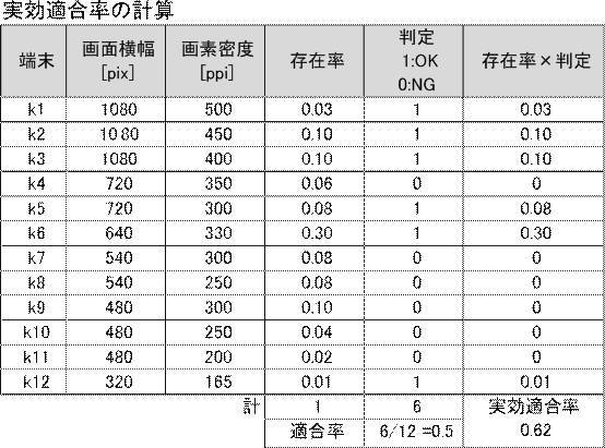
ステップS622で結果を表示したら、ステップS623に進み、処理を終了する。また、参照元のデータベースであるバーコード情報データベース12-1、バーコードスキャナ情報データベース12-2、端末情報データベース12-3の各データベースに新たにデータが登録されるような場合(再度ステップS601乃至ステップS603の何れか又は全てが行われるような場合)には、判定結果も異なったものとなる。このような場合には、この新たなデータにも基づいた判定を行なうために、参照元のデータベースを再度参照し、再度の判定及び判定結果の出力を行なうようにしてもよい(再度のステップS604乃至ステップS623)。
以上説明した本実施例では、複数のバーコードと複数のバーコードスキャナ、及び、複数の端末で、端末画面上にバーコードを表示でき、かつバーコードスキャナで読み取りが可能かどうかを判定することができる。
更に、本実施例では、適合率や実効適合率を算出できることから、総合的な評価を行なうことが可能となる、という効果を奏する。
なお、以下に図7の各領域を特定するための数式を参考のために記載する。
<参考>
モジュール幅Wm=308[mod]、バーコードスキャナの仕様が、最小分解能ds=0.15[mm]、読取可能幅Ws=60[mm]の場合の計算値
P≧t・Pl(Pl=25.4・Wm/Ws) …式(A’)
P≧t・25.4×308/60
P≧130.387・t(Pl=130.387) …(a)
P≦t・Ph(Ph=25.4/ds) …式(B’)
P≦t・25.4/0.15
P≦169.333・t(Pl=169.333) …(b)
W≧t・Wm …式(C)
W≧308・t…(c)
そして、(a)、(b)、(c)の式を同時に満たす領域が、t=1の場合が図7の701の領域、t=2の場合が702の領域、t=3の場合が703の領域となる。
<参考>
モジュール幅Wm=308[mod]、バーコードスキャナの仕様が、最小分解能ds=0.15[mm]、読取可能幅Ws=60[mm]の場合の計算値
P≧t・Pl(Pl=25.4・Wm/Ws) …式(A’)
P≧t・25.4×308/60
P≧130.387・t(Pl=130.387) …(a)
P≦t・Ph(Ph=25.4/ds) …式(B’)
P≦t・25.4/0.15
P≦169.333・t(Pl=169.333) …(b)
W≧t・Wm …式(C)
W≧308・t…(c)
そして、(a)、(b)、(c)の式を同時に満たす領域が、t=1の場合が図7の701の領域、t=2の場合が702の領域、t=3の場合が703の領域となる。
次に、実施例3について説明する。実施例3は、特定のバーコードスキャナと複数の端末を使用することを想定したときに、端末上に表示可能で、かつ、この特定のバーコードスキャナで読み取りが可能となる、最適なバーコードのモジュール幅(又は、バーコードのエンコード桁数)を決定する評価装置に関するものである。
本実施例は、端末で表示でき、かつバーコードスキャナで読み取りが可能な範囲で、できるだけバーコードシンボルの幅(エンコード桁数)を大きくしたいという目的を実現する手段として有効である。
本実施例における評価装置10の構成は、図3を参照して説明した実施例1や実施例2の構成と同様であるため、再度の説明を省略する。
次に、或るバーコードスキャナの仕様に対し、少なくともこの或るバーコードスキャナで読み取りできるバーコードのモジュール幅を決定するための処理について、図8のフローチャートを参照して説明する。
まず、後段の処理において、エンコード桁数を与えると、バーコードを構成するのに必要なモジュール幅を算出できるようにする必要がある。そのため、モジュール幅を算出するために必要な情報である、バーコードの種類や、付帯情報の入力を受け付ける(ステップS801)。ここで、バーコードの種類とは、例えばCODE128やCODABARといったものである。また、付帯情報とは、例えばCODE128であればCodeSetC、CODABARであればNW比・キャラクタ間ギャップといった情報である。なお、コード種別により特定されるバーコードの種類及びバーコード構成条件に応じたモジュール幅Wmの具体的な計算式については、表1を参照して前述している通りである。
次に、ステップS802において、検討の対象となるバーコードスキャナの情報を受け付ける。具体的には、バーコードスキャナを識別するための情報(例えば、バーコードスキャナの名称)と、「使用を想定するバーコードスキャナの仕様」である最小分解能ds[mm]及び読取可能最大幅Ws[mm]の入力を受け付ける。
受け付けた各情報は、バーコードスキャナ情報データベース12-2に格納してステップS803に進む。なお、本実施例におけるバーコード情報データベース12-1及びバーコードスキャナ情報データベース12-2は、実施例2におけるバーコード情報データベース12-1及びバーコードスキャナ情報データベース12-2とそれぞれ同等のものであり評価装置10の記憶装置群12に含まれる何れかの記憶装置により実現されるものとする。
また、今回の処理に伴って実行されるステップS802において情報が入力されても良いが、入力されるべき情報の一部又は全部を、予め、バーコードスキャナ情報データベース12-2に記録しておくようにしても良い。また、評価装置10に、ネットワークを介したデータ通信を行なうための通信部を更に含ませるようにしても良い。そして、バーコードスキャナ情報データベース12-2に格納する情報の一部又は全部を、通信部を介したデータ通信により、外部の装置から取得するようにしても良い。
続いて、ステップS803では、検証すべきバーコードのモジュール幅の最大値Wbをバーコードスキャナの仕様情報に基づいて算出する。
具体的には、少なくとも、バーコードスキャナの仕様とバーコードの幅が「端末の仕様によらず不適」とならないための条件、すなわち、

すなわち、バーコードのモジュール幅の最大値Wbは
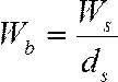
…との式で算出できる。Wbは検証すべきバーコードのモジュール幅の最大値となる。
例えば、バーコードスキャナの読取可能幅Ws=60[mm]、最小分解能ds=0.15[mm]の場合、上記の式に基づいて

となり、Wb=400と算出できる。
ステップS804では、検証すべきバーコードのモジュール幅の最小値Waをバーコードスキャナの仕様情報から算出する。具体的には、次のような考え方で算出する。
図1の様に、P-W平面上、バーコードのモジュール幅とバーコードスキャナの仕様からから適合する領域を示すことができるが、例えば、1モジュールあたりの構成ドット数t=1の適合領域である101の領域の右端(P=Ph)とt=2の適合領域である102の領域の左端(P=2Pl)の間に隙間ができ、この隙間の領域に端末の画面仕様があると、「バーコードとバーコードスキャナがその端末とは適合しない」という結果を導いてしまう。そのため、t=1の適合領域である101の領域の右端(P=Ph)とt=2の適合領域である102の領域の左端(P=2Pl)の間の隙間を考え、理想的には、この隙間がゼロ以下であれば、より「適合する範囲」を広げることができる。具体的には、次のように算出する。
1モジュールあたりのドット数t[dot/mod]のときの左右適合領域のギャップ幅gは次のような式で示すことができる。
g=(t+1)・Pl-t・Ph
各実施例の説明の前提として説明した、式(A’)、式(B’)から、
各実施例の説明の前提として説明した、式(A’)、式(B’)から、
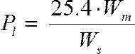


ギャップgが0以下であるためには、g≦0、つまり

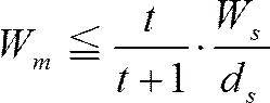
t=1とt=2の適正領域のギャップを考え、t=1を代入すると、

この条件を満たすWmの最大値をWaとする。
すなわち、バーコードのモジュール幅の最小値Waは、
すなわち、バーコードのモジュール幅の最小値Waは、

…との式で算出できる。また、Waは前述の「隙間」の幅が0以下となる最大値で、Wmがこの値より大きくなるにつれ、「適合しない」端末が増加する。
例えば、バーコードスキャナの読取可能幅Ws=60[mm]、最小分解能ds=0.15[mm]の場合、上記の式から

次に、ステップS803及びステップS804でそれぞれ算出したWaとWbを用いて、

となる範囲のバーコードのモジュール幅Wが検査対象として決定する(ステップS805)。
例えば、バーコードスキャナの読取可能幅Ws=60[mm]、最小分解能ds=0.15[mm]の場合、前述したように式(D)に基づいた式
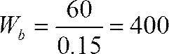
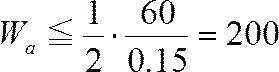

このとき、桁数n(整数)に対してバーコードの全体モジュール幅Wを算出する式を、バーコード種類別計算式格納部12-5を参照して取得する。ここで、桁数n(整数)に対してバーコードの全体モジュール幅Wを算出する式は、コード種別情報及び付帯情報に応じて異なる。そのため、ステップS801で入力を受け付けたコード種別情報及び付帯情報に対応する式を取得する。ここで、バーコード種類別計算式格納部12-5は、さまざまなコード種別情報及び付帯情報に対応する、桁数n(整数)に対してバーコードの全体モジュール幅Wを算出する式を格納する部分である。具体的には、バーコード種類別計算式格納部12-5には表1に記載されているような式が格納される。また、バーコード種類別計算式格納部12-5は、評価装置10の記憶装置群12に含まれる記憶装置により実現される。
そして、取得した式に基づいて、Waを超えない最大の桁数na、Wbを超えない最大の桁数nbを求める。つまり、バーコードのモジュール幅Wはエンコード桁数のna桁からnb桁の範囲で求めれば良い。
例えば、バーコードスキャナの読取可能幅Ws=60[mm]、最小分解能ds=0.15[mm]の場合に、対象となるバーコードの種別情報及び付帯情報がGS1-128(EAN-128)のCODESET Cであれば、表1の計算式より、W=11n/2+66であるため、
Wa=11na/2+66、Wb=11nb/2+66、をそれぞれ、na、nbについて解くと、
na…24.36を超えない整数(ただし、CODESET Cなので偶数)=24桁、
nb…60.73を超えない整数(ただし、CODESET Cなので偶数)=60桁、
となり、調査を行うバーコードの桁数の範囲は24桁~60桁と決まる。
Wa=11na/2+66、Wb=11nb/2+66、をそれぞれ、na、nbについて解くと、
na…24.36を超えない整数(ただし、CODESET Cなので偶数)=24桁、
nb…60.73を超えない整数(ただし、CODESET Cなので偶数)=60桁、
となり、調査を行うバーコードの桁数の範囲は24桁~60桁と決まる。
ステップS806ではステップS805で決定した、調査を行うバーコードの桁数の範囲、すなわち、na桁からnb桁の範囲で、バーコードのモジュール幅を算出する。算出には、前述したように、バーコード種類別計算式格納部12-5から取得した式を用いる。
そして、算出した、na桁からnb桁の各桁に対応したバーコードのモジュール幅それぞれを、バーコード情報データベース12-1に格納する。ここで、バーコード情報データベース12-1は、前述したように、実施例2におけるバーコード情報データベース12-1と同等のものであり、評価装置10の記憶装置群12に含まれる何れかの記憶装置により実現されるものとする。
例えば、バーコードスキャナの読取可能幅Ws=60[mm]、最小分解能ds=0.15[mm]の場合に、対象となるバーコードの種別情報がGS1-128(EAN-128)のCODESET Cであれば、調査すべき桁数が24桁~60桁(偶数桁)である。そのため、下記の表9に記載の様に桁数からバーコード幅を算出することで、19種類のバーコードを想定することができる。図8のステップS806ではこれらのバーコードの情報を「バーコード情報データベース12-1」に記録する。
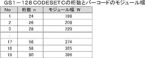
次のステップS807では、実施例2で使用した、図6のフローチャートに記載の処理を活用すべく、図6のステップS603を呼び出す。そして、図6のステップS603から図6のフローチャートに記載の処理を行い、想定する端末の仕様情報を入力して実施例2と同様の手法で評価処理を行う。
この時、バーコードスキャナの仕様情報はステップS802で入力を受け付けてバーコードスキャナ情報データベース12-2に格納した情報を用いる。また、バーコードのモジュール幅の情報はステップS806でバーコード情報データベース12-1に格納した情報を用いる。
図6のフローチャートに記載の処理を行い、判定結果を得たら、図8のステップS808に戻り、結果の分析を行う。図6のフローチャートに記載の処理の処理結果から、実施例2と同様にバーコードのモジュール幅別の適合率を計算し、計算結果を表示装置21に表示する。
例えば、バーコードスキャナの読取可能幅Ws=60[mm]、最小分解能ds=0.15[mm]であるとする。また、対象となるバーコードの種別及び付帯情報がGS1-128(EAN-128)のCODESET Cであるとする。更に、調査すべき桁数が24桁~60桁(偶数桁)であるとする。更に、表示を想定する端末の仕様を表7のk1~k12であるとする。この場合、その検証結果は下記の表10に記載の様になる。
この時、横軸を桁数、縦軸を適合率としてグラフ化したものが図9である。

次、ステップS809に進み、ステップS808で明らかとなったバーコードのエンコード桁数と適合率の関係から、最適値を導き出す。具体的には、適合率が最も高い条件を検索することによって、最適値を決定する。また、仮に最も高い適合率の条件が複数ある場合には、桁数が最も多い条件を検索することによって、最適値を決定する。
例えば、前述の表10及び図9に表わされる例であれば、適合率が最も高かった1.0となる桁数で最も桁数が多い条件は、桁数が30桁の場合であると分かる。つまりこの場合、桁数が30桁、バーコードのモジュール幅が231[mod]の条件が最適値となる。
このように、ステップS809でバーコードの最適条件を決定してその結果を出力したら、ステップS810で処理を終了する。
なお、例として用いた、バーコードスキャナの読取可能幅Ws=60[mm]、最小分解能ds=0.15[mm]、対象となるバーコードの種別及び付帯情報がGS1-128(EAN-128)のCODESET C、表示を想定する端末が表7のk1~k12とした場合の端末と適合範囲を示すP-W図が図10及び図11に表わされている。具体的には、この場合であって、調査対象の最小桁数である24桁の場合の端末と適合範囲を示すP-W図が図10に表わされている。また、この場合であって、最適桁数として結果が出た30桁の場合の端末と適合範囲を示すP-W図が図11に表わされている。
24桁の場合と比べ、30桁の場合の方が、端末仕様の適合領域(1101の領域、1102の領域及び1103の領域)の面積は小さいが、想定端末の仕様を示す点が全て「適合領域」の中に納まることが分かる。
この場合、「24桁」とは、端末の仕様を考慮せず、バーコードスキャナの仕様とバーコードのモジュール幅から導き出される、適合領域の範囲、すなわち、t=1の場合の適合領域(図10の1001の領域)とt=2の場合の適合領域(図10の1002の領域)の境界が密着するように導き出した桁数である。これに対し、「30桁」は、更に端末の仕様を考慮した場合にできるだけ桁数が多くなるように、すなわち、図11の1101の領域と図11の1102の領域に、図11の端末の仕様を示す点が外れないように導き出した桁数となる。
このようにして導いた「30桁」の場合では、図11の端末k11がt=2の場合の適合領域(図11の1102の領域)の左端に位置する。また、端末k12がt=1の場合の適合領域(図11の1101の領域)の右端に位置する。このことから、バーコードスキャナの仕様とバーコードのモジュール幅のみから導かれた「24桁」の場合より、端末の仕様を考慮することによって、「適合率を維持したまま」6桁多くバーコードを構成できることが分かる。
同じ条件で、桁数が44桁の場合(Wm=308[mod])である図7を見ると、この条件では、12種の端末のうち6種(k4,k7,k8,k9,k10,k11)が「適合領域」の外にあるため、適合率が低下(この条件では適合率0.5)していると分かる。
なお、実施例3は、実施例3としての機能を含む単独の装置として実現してもよいし、実施例1もしくは実施例2としての機能を含む装置の1つの機能として実現してもよい。つまり、実施例3を実施例1や実施例2と組み合わせてもよい。
なお、実施例2と組み合わせるのではなく、単独の装置として実現したり、実施例1と組み合わせる場合には、ステップS807において図6のステップS603以降の処理を呼び出すのではなく、同等の処理を実現するためのプログラム等を装置に実装しておき、このプログラムに基づいて、図6のステップS603の処理を実行するようにすればよい。
以上説明した本実施例では、適合率を考慮した上で、桁数の最適値を決定できることから、端末で表示でき、かつバーコードスキャナで読み取りが可能な範囲で、できるだけバーコードシンボルの幅(エンコード桁数)を大きくすることができる、という効果を奏する。
次に、実施例4について説明する。実施例4は、特定のモジュール幅のバーコードと、バーコードの表示を想定した複数の端末に、バーコードが端末上に表示可能であるとき、そのバーコードを読取可能なバーコードスキャナの仕様を決定するバーコードスキャナ仕様特定装置に関するものである。
本実施例は、特定のモジュール幅のバーコードと、バーコードの表示を想定した複数の端末に、バーコードが端末上に表示可能であるとき、そのバーコードを読み取るために必要とされるバーコードスキャナの仕様を知りたいという目的を実現する手段として有効である。
本実施例である、バーコードスキャナ仕様特定装置10’は、CPU11’、記憶装置群12’、画像出力部13’及びI/O14’を含む。バーコードスキャナ仕様特定装置10’に含まれる各部は、バーコードスキャナ仕様特定装置10’内に設けられたバスライン15’を介して接続される。画像出力部13’には、表示装置21が接続され、I/O14’には、入力装置22が接続される。バーコードスキャナ仕様特定装置10’の構成については図示しないが、図3の評価装置10の構成と同一であり、バーコードスキャナ仕様特定装置10’のCPU11’、記憶装置群12’、画像出力部13’、I/O14’及びバスライン15’は、それぞれ、評価装置10のCPU11、記憶装置群12、画像出力部13、I/O14及びバスライン15に相当する。
また、これら、バーコードスキャナ仕様特定装置10’内の各部の機能は、図3を参照して説明した実施例1、実施例2及び実施例3の評価装置10内に含まれる同名の各部の機能と同様であるため、再度の説明を省略する。
次に、決まったモジュール幅のバーコードと、バーコードの表示を想定した複数の端末から、適切なバーコードスキャナの仕様(最小分解能と読取可能幅)を決定するための処理について、図12のフローチャートを参照して説明する。
まず、ステップS1201では、「ある決まったモジュール幅のバーコード」のバーコードを識別するための情報(例えば、バーコードの名称)と、モジュール幅Wmの入力を受け付ける。受け付けた各情報はバーコード情報データベース12-1に格納してステップS1202に進む。なお、本実施例におけるバーコード情報データベース12-1及び端末情報データベース12-3は、実施例2や実施例3におけるバーコード情報データベース12-1及び端末情報データベース12-3とそれぞれ同等のものでありバーコードスキャナ仕様特定装置10’の記憶装置群12’に含まれる何れかの記憶装置により実現されるものとする。
次に、ステップS1202では、使用を想定する端末の情報、すなわち、端末を識別するための情報(例えば、端末の名称)、画面幅Wk[pix]、画素密度Pk[ppi]の入力を受け付ける。受け付けた各情報は、端末情報データベース12-3に格納してステップS1203に進む。なお、ステップS1201及びステップS1202の何れか又は双方における入力の受け付けを予め行っておき、予め情報を各データベースに記録しておいても良い。また、バーコードスキャナ仕様特定装置10’に、ネットワークを介したデータ通信を行なうための通信部を更に含ませるようにしても良い。そして、各データベースに格納する情報の一部又は全部を、通信部を介したデータ通信により、外部の装置から取得するようにしても良い。
ステップS1203では、端末情報データベース12-3を検索して端末画面幅の最大値Wkmaxを検索して取り出し、ある決まったモジュール幅のバーコードのモジュール幅Wmに対し、

を満たす整数tの最大値、tmaxを求める。このtmaxは後段の処理で用いる。次に、ステップS1204に進む。
例えば、バーコードのモジュール幅Wm=308[mod]、端末が表7に記載の端末k1乃至端末k12の場合、端末画面幅の最大値Wkmaxは端末k1の1080[pix]であるため、
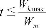
ステップS1204からは、具体的な解析に入る。ステップS1204では繰り返しパラメータとしてtを設け、t=1として、ステップS1205に進む。
ステップS1205では、端末情報データベース12-3から、端末の画面幅Wkに対し、
tWm≦Wk≦(t+1)Wmを満たす端末を抽出し、ステップS1206に進む。
tWm≦Wk≦(t+1)Wmを満たす端末を抽出し、ステップS1206に進む。
例えば、バーコードのモジュール幅Wm=308[mod]、端末が表7に記載の端末k1乃至端末k12で、t=1のとき、ステップS1205で摘出の対象とする「tWm≦Wk≦(t+1)Wmを満たす端末」には、308≦Wk≦616を満たす端末、つまり、端末k7乃至端末k12の6種類の端末が該当する。
ステップS1206では、ステップS1205で抽出した端末の中から、画素密度Pkが最も小さい値を検索し、その値をPkaとし、ステップS1207に進む。
ステップS1207では、ステップS1205で抽出した端末の中から、画素密度Pkが最も大きい値を検索し、その値をPkbとし、ステップS1208進む。
例えば、バーコードのモジュール幅Wm=308[mod]、端末が表7に記載の端末k1乃至端末k12で、t=1のとき、ステップS1205で抽出した端末k7乃至端末k12の6種類の端末について画素密度Pkを調べる。
すると、画素密度が最も小さい値は端末k12の165[ppi](→Pka)、最も大きい値は端末k7の300[ppi](→Pkb)であることが分かる。
ステップS1208では、ステップS1206で取り出した画素密度が最も小さい値Pkaを用いて、

から、P=Pkaのときの、最小モジュール幅の構成ドット数tにおけるバーコードスキャナの読取可能幅WsをWstとして、Wstで解くと、

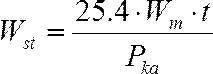
次に、ステップS1209では、ステップS1207で取り出した画素密度が最も大きい値Pkbを用いて、

から、P=Pkbのときの、最小モジュール幅の構成ドット数tにおけるバーコードスキャナの最小分解能dsをdstとして、dstで解くと、

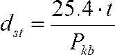
例えば、バーコードのモジュール幅Wm=308[mod]、端末が表7に記載の端末k1乃至端末k12で、t=1のとき、ステップS1205で抽出した端末k7乃至端末k12の6種類の端末の最小画素密度がk12の165[ppi](→Pka)、最大画素密度はk7の300[ppi](→Pkb)であるため、
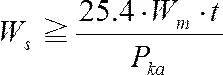
から、Wsの最小値Ws1=25.4×308/165=47.4[mm]と算出される。
また、
また、
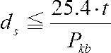
から、dsの最大値ds1=25.4/300=0.0847[mm]と算出される。
ステップS1210に進み、ステップS1208及びステップS1209で計算したWstとdstをtの値と共に、算出結果記録データベース12-6に記録し、ステップS1211に進む。なお、算出結果記録データベース12-6は本実施例における算出結果を格納するデータベースであり、バーコードスキャナ仕様特定装置10’の記憶装置群12’に含まれる何れかの記憶装置により実現されるものとする。
ステップS1211では、現在のtの値がステップS1203で計算したtmax以上であるか否かを判断する。
ここで、現在のtの値がtmax未満であれば(ステップS1211においてNo)、ステップS1212に進み、現在のtの値に1を加算して新たなtの値とする。そして、ステップS1205に戻り、新たなtの値を用いて、再びステップS1205乃至ステップS1210の処理を行う。
一方で、現在のtの値がtmax以上であれば(ステップS1211においてYes)、ステップS1213に進む。
ステップS1213では、算出結果記録データベース12-6を参照し、t=1からt=tmaxで計算された、Wst(Ws1,Ws2…)の中から、最大となる値を取り出す。
また、ステップS1214では算出結果記録データベース12-6を参照し、t=1からt=tmaxで計算された、dst(ds1,ds2…)の中から、最小となる値を取り出す。
そして、ステップS1215では、ステップS1213で取り出されたWstの値と、ステップS1214で取り出されたdstの値を表示装置21に表示する。この時に表示する値が、「ある決まったモジュール幅Wmのバーコードと、バーコードの表示を想定した複数の端末(画面幅Wk、画素密度Pk)に、おける理想的なバーコードスキャナの仕様(読取可能幅:Wstの最大値、最小分解能:dstの最小値)」を示している。
ステップS1215で、Wstの値と、dstの値を表示装置21に表示後、ステップS1216に移行して処理を終了する。
例えば、バーコードのモジュール幅Wm=308[mod]、端末が表7に記載の端末k1乃至端末k12の場合、図12のステップS1203の計算でtmax=3と決まり、算出結果記録データベース12-6に記録される内容は下記の表11に記載の内容となる。

表11から、Wstの最大値、すなわちt=3のときのWs3=58.67[mm]が、バーコードスキャナの理想的な読取可能幅であり、dstの最小値、すなわち、t=1のときのds1=0.0847[mm]がバーコードスキャナの理想的な最小分解能と決まる。
この時、
この時、


から、Ph=300[ppi]、
となるため、端末と適合範囲を示すP-W図は、図13に表わされるようになる。
となるため、端末と適合範囲を示すP-W図は、図13に表わされるようになる。
図13を参照すると、表7に記載の端末k1乃至端末k12の各端末の画面仕様に対応する全ての点が、t=1~3の適合範囲である、1301の領域、1302の領域及び1303の領域の何れかの領域の内側にあり、本実施例で算出したバーコードスキャナの仕様において、想定した全ての端末(表7に記載の端末k1乃至端末k12)の画面でバーコードを表示でき、且つ、読み取りが可能となっていることが分かる。
なお、結果として算出されたバーコードスキャナの仕様(読取可能幅と最小分解能)が、バーコードスキャナの製造技術として技術的にあるいはコスト的に困難な値となった場合、バーコードの幅を減らす(桁数を減らす)、あるいは、表示を想定する端末の種類を絞る等の検討が必要となる。
なお、実施例4は、実施例4としての機能を含む単独の装置として実現してもよいし、実施例1乃至実施例3としての機能を含む装置の1つの機能として実現してもよい。つまり、実施例4を実施例1乃至実施例3と組み合わせてもよい。
以上説明した本実施例では、特定のモジュール幅のバーコードと、バーコードの表示を想定した複数の端末の画面仕様を考慮した上で、バーコードスキャナの仕様を決定する。このことから、本実施例では、特定のモジュール幅のバーコードと、バーコードの表示を想定した複数の端末に、バーコードが端末上に表示可能であるとき、そのバーコードを読み取るために必要とされるバーコードスキャナの仕様を知ることができる、という効果を奏する。
次に、実施例5について説明する。実施例5は、実際に端末画面にバーコードを表示するシステムに関するものである。なお、本実施例で、バーコードを生成するとは、バーコード画像データを生成することを意味するものとする。
まず、図14を参照して、本実施例であるバーコードシステム100の全体の構成例について説明する。
図14を参照すると、バーコードシステム100は、端末群30、端末k31、第1の事業者サーバ41、第2の事業者サーバ42、バーコード生成サーバ50、及び回線網60を含む。
本実施例では、利用者が利用する端末として、端末群30に含まれる、端末k31やその他の複数の端末が存在する。これらの端末は利用者が利用する端末であるが、その機種等は様々であり、当然のことながらその画面仕様も様々である。
なお、以下では、利用者が端末k31を使用する場合を例に取って説明を行なう。
また、第1の事業者サーバ41及び第2の事業者サーバ42は、それぞれバーコードを用いたサービスを提供する事業者が利用するサーバ装置である。本実施例では、事業者Aが第1の事業者サーバ41を利用しており、事業者Bが第2の事業者サーバ42を利用しているものとする。事業者A、事業者Bはそれぞれ異なる目的のサービスを提供していて、それぞれ、サービス提供のために使用するバーコードの種類やエンコード桁数が異なるものとする。なお、第1の事業者サーバ41及び第2の事業者サーバ42は、本発明の、「依頼装置」に相当する。
バーコード生成サーバ50は、本実施例の特徴を利用したバーコードを生成するサーバ装置である。
そして、本システム内に含まれる各端末及び各サーバは、回線網60を介して通信可能に接続される。
具体的には、端末k31は、回線網60を通じて、バーコードを用いたサービスを提供する第1の事業者サーバ41や、第2の事業者サーバ42にアクセスすることができるものとする。
また、バーコードを用いたサービスを提供する第1の事業者サーバ41や第2の事業者サーバ42から、本実施例の特徴を利用したバーコードを生成するバーコード生成サーバ50にアクセスし、バーコードの画像を取得するものとする。
なお、回線網60は、例えば携帯電話網やインターネットの公衆網や、専用線の何れか、あるいはこれらの組み合わせにより実現することができる。
以上説明したバーコードシステム100の構成において、端末k31が事業者Aの第1の事業者サーバ41にアクセスし、事業者Aの第1の事業者サーバ41を介して端末k31にバーコードを表示する場合について以下説明する。
事業者Aは、運用前提として、使用するバーコードの種類とエンコードする桁数、その他、選択するバーコードの種類によって構成に必要な付帯情報(例えば、NW7ならNW比、等)、及び、端末k31からアクセスされた場合に表示すべきエンコード文字列の内容を事前に決めておく。また、想定するバーコード読取装置(バーコードスキャナ)の読取可能幅Ws[mm]、最小分解能ds[mm]を決めておく。
端末k31から、第1の事業者サーバ41にアクセス(HTTPアクセス)があった場合、第1の事業者サーバ41には、端末k41の基礎情報として、端末名、OS、ブラウザの種類といった情報を含む、user agentと呼ばれる情報が通知される。また、第1の事業者サーバ41は、端末k41の画面情報を、web apiによって、画面幅はwindow.screen.width、画面高さはwindowscreen.heightを用いて取得することができる。つまり、第1の事業者サーバ41では、端末k31のアクセスによって、user agent情報と画面幅・高さ情報を得ることができる。また、サービス利用者が第1の事業者サーバ41にログインする形態をとって、利用者の管理番号を取得し、この管理番号に基づいてuser agent情報に準じる情報や画面幅・高さ情報を特定するようにしてもよい。
なお、端末によっては、画面の物理的な回転状態によって、window.screen.widthとwindowscreen.heightが入れ替わる場合がある。この点、本実施例では、window.screen.width<windowscreen.heightとして取り扱う。つまり、端末画面の「画面幅」は常に画面短手方向を、「画面高」は常に長手方向を示すものとする。
第1の事業者サーバ41では、前述のuser agent情報と端末画面の「画面幅」「画面高」情報と、事業者Aが使用したいバーコードの種類(及び関連パラメータ等の補足情報)と桁数、及びエンコード文字列、更に、事業者Aが想定するバーコードスキャナの仕様の読取可能幅Ws[mm]、最小分解能ds[mm]を、バーコード生成サーバ50に伝達する。
バーコード生成サーバ50では、第1の事業者サーバ41から伝達された各種情報と、バーコード生成サーバ50内の端末情報データベースを利用して、バーコード画像と、適合性を評価し、その結果を第1の事業者サーバ41に送信する。
第1の事業者サーバ41では、バーコード生成サーバ50で作成されたバーコード画像と適合性情報とをもとに端末k31に、バーコード生成サーバ50で作成されたバーコード画像を端末k31の画面に表示させる否かを判断する。そして、問題が無ければバーコード生成サーバ50で作成されたバーコード画像を端末k31の画面に表示させる。適合性情報から問題ありと判断する場合は、バーコード画像を表示しないか、別のパラメータでバーコード生成サーバ50に改めて送信し、新たなバーコード画像の取得を試みることができる。
また、バーコード生成サーバ50は要求されたバーコードを要求元の条件に従って作成できる。そのため、例えば、事業者Aと異なる事業者である事業者Bが利用する第2の事業者サーバ42からの、別のバーコード種別や桁数のデータ要求に応答することができ、バーコード種別やエンコード桁数は固定されない点が特徴となる。
バーコード生成サーバ50の処理について、この処理を表すフローチャートが記載された図15-1、図15-2及び図15-3を参照して説明する。
バーコード生成サーバの処理は図15-1のステップS1501から始まり、この時、第1の事業者サーバ41から、各種情報(図中では、符号41-1を付す)を得て、ステップS1502に進む。ここで、かかる各種情報とは、
「・端末kのuser agent情報
・端末kの画面幅Wk
・端末kの画面高Hk
・想定バーコードスキャナの読取可能幅Ws
・想定バーコードスキャナの最小分解能ds
・バーコードの種類、構成パラメータ等の付帯情報
・バーコードの桁数、エンコード文字列」である。
「・端末kのuser agent情報
・端末kの画面幅Wk
・端末kの画面高Hk
・想定バーコードスキャナの読取可能幅Ws
・想定バーコードスキャナの最小分解能ds
・バーコードの種類、構成パラメータ等の付帯情報
・バーコードの桁数、エンコード文字列」である。
ステップS1502ではステップS1051で得た情報から、バーコードのモジュール幅Wmを算出する。この時、バーコードシンボルの種類、構成パラメータ、バーコードの桁数及びエンコード文字列に基づいて、実施例1の説明の際に参照した表1の様に、バーコードのモジュール幅Wmは一意に決まる。
次に、ステップS1503に進み、ステップS1501で得たuser agent情報と端末画面幅情報、端末画面高情報から、端末の種別を分類する。例えば、android(登録商標) OSを用いた携帯端末と、iOS(登録商標)を用いた携帯端末を適合対象として仕分ける場合について考える。この場合、user agentの文字列に、”android”と”mobile”の文字列が同時に存在すれば、android OSを用いた携帯端末と判定できる。また、user agentの文字列に、”iPhone(登録商標)”の文字列があり、”iPad(登録商標)”、”iPod(登録商標)”の文字列が無ければ、iOSを用いた携帯端末と分かる。そして、iOSを用いた携帯端末と分かれば、端末kの画面幅Wkが320[pix]ならiPhone3GS、Wkが640[pix]なら、iPhone4/4S/5/5C/5Sであると分かる。更に、iPhone4/4S/5/5C/5Sであると分かった場合に、端末kの画面高Hkが960[pix]ならiPhone4/4Sの何れかであり、1136[pix]ならiPhone5/5C/5Sの何れかである、と細分化することができる。
次に、ステップS1503における分類結果に基づいて、端末kの種別がPC(personal computer)やタブレット端末であるか否かを判定する(ステップS1504)。ここで、端末kの種別が、ステップS1503の分類から漏れる、PC(personal computer)やタブレット端末といったものである場合には(ステップS1504においてYes)、ステップS1505でフラグ=Fとして、(A)=ステップS1535)に進む。なお、図中では(A)を丸囲み英数字で表記する。以下(B)及び(C)についても同様とする。
一方、ステップS1503における分類結果に基づいて、端末kがPCやタブレット端末と判断されなかった場合には(ステップS1504においてNo)、ステップS1506に進む。
ステップS1506では、再びuser agent情報を解析し、この文字列の中から端末kの端末機種名を抽出し、ステップS1507に進む。
ステップS1507では、ステップS1506で取得した端末機種名を検索キーとして端末機種情報データベース50-1を検索することにより、端末機種情報データベース50-1から改めて、端末の画面幅Wk、画面高Hk、画素密度Pkを取得する。ここで、この端末機種情報データベース50-1は、端末のメーカ等が公開している公開情報等の既知の情報を事前にまとめて、データベースとしたものである。なお、端末機種情報データベース50-1、生成送信ログ50-2及び未知端末情報データベース50-3は、それぞれ、バーコード生成サーバ50がアクセス可能な、バーコード生成サーバ50内部又は外部の記憶装置に記憶されるものとする。なお、図中では、データベースを適宜DBと表記する。
次に、端末機種情報データベース50-1に端末kの端末機種名に対応する端末機種名が存在するか否かを判断する(ステップS1508)。
端末機種情報データベース50-1に端末kの端末機種名に対応する端末機種名が存在しない場合には(ステップS1508においてNo)、ステップS1509に進み、「未知の端末」としてフラグをCにセットし、(B)=図15-3のステップS1521に進む。一方で、端末機種情報データベース50-1に端末kの端末機種名に対応する端末機種名が存在する場合には(ステップS1508においてYes)、「既知の端末」と確認して(ステップS1510)、ステップS1511に進む。
ステップS1511では、ステップS1502で算出したWmとステップS1507で取得したWkを比較する。そして、Wk<Wmであれば(ステップS1511においてNo)、端末の画面幅が表示すべきバーコードの幅より狭いということとなる。そのため、「端末にバーコードを表示できない」と判断してステップS1512に進み、フラグをEにセットし、(A)=ステップS1535に進む。
一方、Wk≧Wmならば(ステップS1511においてYes)、ステップS1513に進む。
なお、ステップS1511における比較は、各実施例の説明の前提として前述した式(C)に相当する。
W≧t・Wm …式(C)
次に、ステップS1513では、1モジュールあたりの構成ドット数をt[dot/mod]として、t≦Wk/Wmとなる正の整数tの最大値tmaxを求め、ステップS1514に進む。
次に、ステップS1513では、1モジュールあたりの構成ドット数をt[dot/mod]として、t≦Wk/Wmとなる正の整数tの最大値tmaxを求め、ステップS1514に進む。
例えば、バーコードのモジュール幅Wm=300[mod]、端末の画面幅Wk=720[dot]とすると、
t≦720/300→t≦2.4…となり、tmax=2となる。
t≦720/300→t≦2.4…となり、tmax=2となる。
ここで求められるtmaxは、端末の画面に表示できる最大の1モジュールあたりの構成ドット数であり、その時のバーコードの幅は、tmax・Wmと表すことができる。
次に、図15-2を参照する。ステップS1514では、tmax~1の範囲で、バーコードの最小モジュール幅がバーコードスキャナの最小分解能より大きく、且つ、端末画面上に表示したときのバーコードの幅がバーコードスキャナの読取可能幅以下であるか否かを判定する。
具体的には次のように計算する。


の2つの関係式に基づき、
式(A’)から、A=Pk-25.4・t・Wm/Ws、という計算を行う。
式(A’)の関係式が成立していれば、Aは正の値をとる。
次に、式(B’)から、B=25.4・t/ds-Pk、という計算を行う。
式(B’)の関係式が成立していれば、Bは正の値をとる。
式(A’)から、A=Pk-25.4・t・Wm/Ws、という計算を行う。
式(A’)の関係式が成立していれば、Aは正の値をとる。
次に、式(B’)から、B=25.4・t/ds-Pk、という計算を行う。
式(B’)の関係式が成立していれば、Bは正の値をとる。
例えば、tmax=2、バーコードのモジュール幅Wm=300[mod]、端末の画素密度Pk=300[dpi]、バーコードスキャナの読取可能幅Ws=60[mm]、バーコードスキャナの最小分解能ds=0.15[mm]とすると、次のような表(表12)を作ることができる。
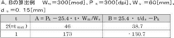
ステップS1515で、ステップS1514で求められたA、Bそれぞれの値をチェックし、A、Bともに正となるtが存在するか確認する。「A、Bともに正となるtが存在する」場合には(ステップS1515においてYes)、ステップS1517に進む。
ここで、「A、Bともに正となるtが存在する」とは、すなわち、式(A’)、式(B’)が同時に成立するtが存在する、つまり、バーコード、端末画面仕様、バーコードスキャナ仕様が適合していることを示す。
表12の例では、t=2のときに、「A、Bともに正」なので(ステップS1515においてYes)、ステップS1517に進むことができる。
ステップS1517では、「A、Bともに正」となるtの最大値(表12の例ではt=2)を、tの値として選択し、ステップS1518に進む。
ステップS1518では、「適正範囲」でバーコード画像を作製できるという意味で、フラグをAにセットして、ステップS1519に進む。
一方、ステップS1514で求めるA、Bが、ともに正となるtが存在しない場合、すなわち、式(A’)、式(B’)が同時に成立するtが存在しない場合には(ステップS1515においてNo)、ステップS1516に進む。ここで、式(A’)、式(B’)が同時に成立するtが存在しないとは、つまり、バーコード、端末画面仕様、バーコードスキャナ仕様が適合しないことを示す。
例えば、表13の例(tmax=2、バーコードのモジュール幅Wm=300[mod]、端末の画素密度Pk=250[dpi]、バーコードスキャナの読取可能幅Ws=60[mm]、バーコードスキャナの最小分解能ds=0.15[mm])の場合、t=1の場合はBが負の値となり、t=2の場合はAが負の値となる。つまり、A及びBがともに正となるtは存在しない(ステップS1515においてNo)。このため、ステップS1516に進む。

ステップS1516では、負の値となったA又は負の値となったBの絶対値が最も小さくなるtをtの値として選択する。
この時、選択したtで負の値となった値がAであれば、フラグをBa、Aの絶対値をPkで割った値(|A|/Pk)を戻り値としてセットする。
一方で、選択したtで負の値となった値がBであれば、フラグをBb、及びBの絶対値をPkで割った値(|B|/Pk)を戻り値としてセットし、ステップS1519に進む。
ここで、|A|/Pkや|B|/Pkは、「適正範囲」から、どの程度外れているかを定量的に示す指標となる。
例えば、上記の表13に記載の例では、t=2のときにAの値が負であり、t=1のときにBの値が負である。そして、t=2のときにAの絶対値とt=1のときにBの絶対値
を比較すると、t=2のときのAの絶対値が最も小さいため、t=2と決定する。この時、「適正範囲」から、どの程度外れているかを定量的に示す指標は、|A|/Pk=0.016(1.6%)となる。この値が大きければ大きいほど、端末上に表示されたバーコードが読み取りできない可能性が高くなることを意味する。
を比較すると、t=2のときのAの絶対値が最も小さいため、t=2と決定する。この時、「適正範囲」から、どの程度外れているかを定量的に示す指標は、|A|/Pk=0.016(1.6%)となる。この値が大きければ大きいほど、端末上に表示されたバーコードが読み取りできない可能性が高くなることを意味する。
ステップS1519では、ステップS1517又はステップS1516で決定したtの値と、ステップS1502で得た第1の事業者サーバ41からの情報のバーコードの種類、構成パラメータ等の付帯情報及びエンコードデータと、端末画面密度Pkを用いてバーコード画像を生成する。
この時、バーコードは1モジュールあたりt[dot]で構成し、バーコードの画像の幅はt・Wmとなる。対象のバーコードの種類がいわゆる1次元のバーコードであれば、高さは端末画面上で10mmとなるように、25.4/Pk×10[mm]を計算したドット数(正数値)とする。バーコード画像が完成したら、ステップS1535に進む。なお、前述したフラグEとなった場合には、端末kにて表示可能なバーコード画像を生成することはできない。また、前述したフラグFとなった場合には、端末kは携帯端末ではない。そのため、これらフラグE及びフラグFとなった場合には、バーコード画像を生成することなく、ステップS1535に進む。
ステップS1535では、作成したバーコード画像に、フラグに応じたコメントを入れる。ステップS1535は、構成したバーコードの適正度を明確にするためにコメントを文字列として画像に埋め込む処理であるが、文字が必要なければこのステップS1535の処理は無くても良い。
ここで、ステップS1535にてフラグに応じて画像に入れられる文字列は、例えば以下のようにする。
「・フラグA:「ご使用の端末画面上のバーコードを読み取らせてください。」
・フラグBa、Bb:「ご使用の端末ではバーコードを読み取りできない場合があります。」
・フラグC:「ご使用の端末ではバーコードを読み取りできない場合があります。」
・フラグDa、Db:「ご使用の端末ではバーコードを読み取りできない場合があります。」
・フラグE、Dc、De:「ご使用の端末ではバーコードを表示できません。」
・フラグF:「ご使用の端末は携帯端末ではありません。」」なお、これらの文字列は一例に過ぎず、他の文言を使用するようにしてもよい。
「・フラグA:「ご使用の端末画面上のバーコードを読み取らせてください。」
・フラグBa、Bb:「ご使用の端末ではバーコードを読み取りできない場合があります。」
・フラグC:「ご使用の端末ではバーコードを読み取りできない場合があります。」
・フラグDa、Db:「ご使用の端末ではバーコードを読み取りできない場合があります。」
・フラグE、Dc、De:「ご使用の端末ではバーコードを表示できません。」
・フラグF:「ご使用の端末は携帯端末ではありません。」」なお、これらの文字列は一例に過ぎず、他の文言を使用するようにしてもよい。
ステップS1535でバーコードを含む画像が完成したら、ステップS1536に進む。この時、前述したようにフラグE及びフラグFとなった場合や、後述するフラグがE、Dc、De、Fの場合はバーコードを構成できないため、画像にバーコードは含まれないことになる。
ステップS1536では、生成された画像と、フラグ、戻り値を、生成送信ログ50-2に記録する。また併せてステップS1536では、第1の事業者サーバ41に生成された画像と、フラグ、戻り値を返信し、処理を終了する(ステップS1537)。
その後、生成された画像は、第1の事業者サーバ41から携帯端末k31に対して送信される。そして、生成された画像にバーコードが含まれているのであれば、かかるバーコードを携帯端末k31の画面上に表示する。これにより、ユーザは、バーコードスキャナでかかるバーコードを読み取ることが可能となる。
また、バーコードを生成した場合であっても、生成していない場合であってもステップS1535にて入れられた文字列を携帯端末k31の画面上に表示することが可能となる。そして、ユーザは、この文字列を参照することにより、予めバーコードが読み取れるか否か等を判断することが可能となる。
次に、ステップS1508で端末機種情報データベース50-1に、端末kの情報が無いと判断された場合(ステップS1508においてNo)の処理について説明する。
この場合、前述したように、ステップS1509で「未知の端末」としてフラグをCにセットし、(B)=図15-3のステップS1521に進む。
図15-3のステップS1521では、再度、端末機種情報データベース50-1を参照し、画像幅がWkと同じ端末の中で、最も多い画素密度Pkの値、つまり中央値を呼び出す。これは、未知の端末kの画素密度が不明であるため、端末kの画面幅であるWkと画像幅が同じ端末の中で、最も存在しうるPkの値を呼び出すことを目的としている。
次に、画像幅がWkと同一の他の端末が、端末機種情報データベース50-1に存在するか否かを確認する(ステップS1522)。つまり、ステップS1521において画像幅WkからPkの中央値を呼び出せたか否かを確認する。
ここで、画像幅がWkと同じ端末の画素密度Pkの中央値を呼び出すことができていれば(ステップS1522においてNo)、ステップS1524に進み、ここで呼び出した値を未知の端末kの仮の画素密度Pkとする。その後、ステップS1525に進む。
一方で、ステップS1522で画像幅がWkと同じ端末の画素密度Pkの中央値を呼び出すことができなければ、ステップS1523で「未知の端末、且つ、未知の画面幅」という意味で、フラグをDeにセットし、(A)=図15-1のステップS1535に進む。ステップS1535以降の処理については前述した通りである。
ステップS1525では、未知端末情報データベース50-3に、端末kの機種名k、端末kの画面幅Wk、端末kの画面高Hk、ステップS1524で決定した仮の画素密度Pkを記録して、ステップS1526に進む。
ここで、未知端末情報データベース50-3は、後にどのような未知端末があったかを確認する用途等に利用でき、端末情報データベース50-1をメンテナンスする際の情報源の一つとして活用できる。
ステップS1526では、ステップS1502で算出したWmとステップS1507で取得したWkを比較する。
そして、Wk<Wmであれば(ステップS1526においてNo)、端末の画面幅が表示すべきバーコードの幅より狭いということとなる。そのため、「端末にバーコードを表示できない」と判断されてステップS1527に進み、フラグをDcにセットし、(A)=図15-2のステップS1535に進む。ステップS1535以降の処理については前述した通りである。
一方で、ステップS1526でWk≧Wmならば(ステップS1526においてYes)、ステップS1528に進む。
ステップS1528では、1モジュールあたりの構成ドット数をt[dot/mod]として、t≦Wk/Wmとなる正の整数tの最大値tmaxを求め、ステップS1529に進む。
ステップS1529では、tmax~1の範囲で、A=Pk-25.4・t・Wm/Ws とB=25.4・t/ds-Pkを求め、ステップS1530に進む。ステップS1528及びステップS1529における処理の内容及び処理を行なう理由は、図15-1のステップS1513及び図15-2のステップS1514における処理の内容及び処理を行なう理由と同様である。
ステップS1530で、ステップS1529で求められたA,Bそれぞれの値をチェックし、A,Bともに正となるtが存在するか確認する。「A、Bともに正となるtが存在する」場合には(ステップS1530においてYes)、ステップS1532に進む。
ステップS1532では、「A、Bともに正」となるtの最大値を、tの値として選択し、ステップS1533に進む。
ステップS1533では、端末kは未知の端末であるが、仮の画素密度Pkにおいて「適正範囲」でバーコードを作製できるという意味で、フラグをCにセットして、ステップS1534に進む。
一方、ステップS1529で求めたA、Bにおいて「A、Bともに正」となるtが存在しない場合には(ステップS1530においてNo)、ステップS1531に進む。なお、この場合は、ステップS1515においてNoだった場合と同様に、バーコード、端末画面仕様、バーコードスキャナ仕様が適合しないことを示している。
ステップS1531では、図15-2のステップS1516の処理と同様、A又はB値のどちらかが負となっているので、負の値となっているA又は負の値となっているBの絶対値が最も小さくなるtをtの値として選択する。
この時、選択したtで負の値となった値がAであれば、フラグをCa、及びAの絶対値をPkで割った値(|A|/Pk)を戻り値としてセットする。一方で、選択したtで負の値となった値がBであれば、フラグをCb、及びBの絶対値をPkで割った値(|B|/Pk)を戻り値としてセットする。そして、何れの場合であっても、セットの後に、ステップS1534に進む。
ステップS1534は図15-2のステップS1519に相当する。ステップS1534では、決定したtの値と、図15-1のステップS1502で得た第1の事業者サーバ41からの情報のバーコードの種類、構成パラメータ等の付帯情報及びエンコードデータと、端末画面密度Pkを用いてバーコード画像を生成する。
この時、バーコードシンボルは1モジュールあたりt[dot]で構成し、バーコードの画像の幅はt・Wmとなる。対象のバーコードの種類がいわゆる1次元のバーコードであれば、高さは端末画面上で10mmとなるように、25.4/Pk×10[mm]を計算したドット数(正数値)とする。バーコード画像が完成したら、(A)=図15-2のステップS1535に進む。なお、前述したフラグDc、フラグDe及びフラグEとなった場合には、端末kにて表示可能なバーコード画像を生成することはできないので、この場合には、バーコード画像を生成することなく、ステップS1535に進む。ステップS1535以降の処理については前述した通りである。
以上が、バーコード生成サーバ50の処理フローである。
以上説明した本実施例では、バーコードの表示を想定した端末の画面仕様と、バーコードの読み取りを想定したバーコードスキャナの仕様と、を考慮したうえで、各事業者毎に内容の異なるバーコードを生成することができる、という効果を奏する。
また、生成したバーコードを端末の画面上に表示した場合に、フラグに応じた、読み取りができるか否かに関する情報も表示させることが可能となる。そして、ユーザが、この文字列を参照することにより、予めバーコードが読み取れるか否か等を判断することが可能となる、という効果を奏する。
なお、前述した実施形態は、本発明の好適な実施形態ではあるが、上記実施形態のみに本発明の範囲を限定するものではなく、本発明の要旨を逸脱しない範囲において種々の変更を施した形態での実施が可能である。
例えば、上述した実施例5では、バーコード生成サーバを複数の事業者のサーバとは別に設けているが、事業者のサーバ毎にバーコード生成サーバを設けてもよい。つまり、バーコード生成サーバと事業者のサーバの関係は、1対多であってもよいが、1対1であってもよい。更に、バーコード生成サーバと事業者のサーバをそれぞれ別個に設けるのではなく、各事業者のサーバがバーコード生成する機能を含むようにしてもよい。
また、上述した、実施例1乃至5では、構成するバーコードの全体モジュール幅を基準とし、1モジュールあたりのドット数tを選定している。つまり、同じエンコード桁数について、1行で表現することを前提としている。
しかし、GS1 Databar Expandedと呼ばれる(一次元)バーコードでは、同じエンコード桁数について1行で表現できるだけでなく、同じエンコード桁数について複数行で表現することが可能である。そのため、この点も考慮してバーコードの適切な横幅を選択するようにしてもよい。
このバーコードの適切な横幅の選択について、図16及び図17に記載されている具体例を参照して説明する。図16はGS1 Databar Expandedで数字31桁を1行で構成した例を表す図である。また、図17は図16と同じエンコード内容で、2行で構成した例を表す図である。なお、エンコード内容を複数行で表現する場合は、GS1 Databar Expanded Stackedと呼ばれる。
図16では、有効なバーコードの全体幅が249[mod]であるが、図17の様に2行で構成することによって、同じ内容でも151[mod]の幅でバーコードを表示することができる。一方で、バーコードスキャナで読み取る場合は、図16の例も図17の例でも等しく同じデータとして取り扱われる。
このように、同じバーコード種でバーコードの全体幅を減らす手段があるものは、その手段を使用することを想定するようにしても良い。例えば、図16の様な、GS1 Databar Expandedであれば、1モジュールあたりのドット数tを選定するだけでなく、バーコードを表現する行数を決定してバーコードの適切な横幅を選択するプロセスを加えても良い。
なお、上記の評価装置、端末、バーコードスキャナ及び各サーバのそれぞれは、ハードウェア、ソフトウェア又はこれらの組み合わせにより実現することができる。また、上記の評価装置、端末、バーコードスキャナ及び各サーバにより行なわれる各方法も、ハードウェア、ソフトウェア又はこれらの組み合わせにより実現することができる。ここで、ソフトウェアによって実現されるとは、コンピュータがプログラムを読み込んで実行することにより実現されることを意味する。
プログラムは、様々なタイプの非一時的なコンピュータ可読媒体(Non-transitory computer readable medium)を用いて格納され、コンピュータに供給することができる。非一時的なコンピュータ可読媒体は、様々なタイプの実体のある記録媒体(tangible storage medium)を含む。非一時的なコンピュータ可読媒体の例は、磁気記録媒体(例えば、フレキシブルディスク、磁気テープ、ハードディスクドライブ)、光磁気記録媒体(例えば、光磁気ディスク)、CD-ROM(Read Only Memory)、CD-R、CD-R/W、半導体メモリ(例えば、マスクROM、PROM(Programmable ROM)、EPROM(Erasable PROM)、フラッシュROM、RAM(random access memory))を含む。また、プログラムは、様々なタイプの一時的なコンピュータ可読媒体(transitory computer readable medium)によってコンピュータに供給されてもよい。一時的なコンピュータ可読媒体の例は、電気信号、光信号、及び電磁波を含む。一時的なコンピュータ可読媒体は、電線及び光ファイバ等の有線通信路、又は無線通信路を介して、プログラムをコンピュータに供給できる。
本願は、日本の特願2014-240881(2014年11月28日に出願)に基づいたものであり、又、特願2014-240881に基づくパリ条約の優先権を主張するものである。特願2014-240881の開示内容は、特願2014-240881を参照することにより本明細書に援用される。
本発明の代表的な実施の形態が詳細に述べられたが、様々な変更(changes)、置き換え(substitutions)及び選択(alternatives)が請求項で定義された発明の精神と範囲から逸脱することなくなされることが理解されるべきである。また、仮にクレームが出願手続きにおいて補正されたとしても、クレームされた発明の均等の範囲は維持されるものと発明者は意図する。
上記の実施形態の一部又は全部は、以下の付記のようにも記載されうるが、以下には限られない。
(付記1) バーコード画像の画像表示装置での表示の可否の判断及び表示されたバーコード画像のバーコード読取装置での読み取りの可否の判断を行うことである評価を、
前記バーコード画像の内容、前記画像表示装置の仕様及び前記バーコード読取装置の仕様に基づいて、実際に表示及び読み取りをすることなく行なうことを特徴とするバーコード評価装置。
前記バーコード画像の内容、前記画像表示装置の仕様及び前記バーコード読取装置の仕様に基づいて、実際に表示及び読み取りをすることなく行なうことを特徴とするバーコード評価装置。
(付記2) 前記評価を、所定のバーコード画像、所定の画像表示装置及び所定のバーコード読取装置について行い、評価の結果を出力することを特徴とする付記1に記載のバーコード評価装置。
(付記3) 画像表示装置の仕様を表す値を座標軸とした座標系を生成し、
所定のバーコード読取装置によって読み取り可能に所定のバーコード画像の表示するために前記画像表示装置に要求される仕様の範囲を前記座標系上に領域として表すと共に、前記評価の対象とした画像表示装置の仕様に対応する座標を前記平面上に点として表すことにより、
前記評価対象とした画像表示装置の仕様が前記要求される仕様の範囲に含まれるか否か、及び含まれない場合にはどの程度前記要求される仕様の範囲から外れているのかを視認可能に出力することを特徴とする付記1又は2に記載のバーコード評価装置。
所定のバーコード読取装置によって読み取り可能に所定のバーコード画像の表示するために前記画像表示装置に要求される仕様の範囲を前記座標系上に領域として表すと共に、前記評価の対象とした画像表示装置の仕様に対応する座標を前記平面上に点として表すことにより、
前記評価対象とした画像表示装置の仕様が前記要求される仕様の範囲に含まれるか否か、及び含まれない場合にはどの程度前記要求される仕様の範囲から外れているのかを視認可能に出力することを特徴とする付記1又は2に記載のバーコード評価装置。
(付記4) 前記評価を、所定の1つもしくは複数のバーコード画像、所定の1つもしくは複数の画像表示装置及び所定の複数のバーコード読取装置の複数の組み合わせについて行い、評価の結果を出力することを特徴とする付記1に記載のバーコード評価装置。
(付記5) 所定のバーコード画像及び所定のバーコード読取装置からなる所定の組と、前記所定の複数の画像表示装置それぞれとについての複数の評価の結果に基づいて、
前記所定のバーコード読取装置で読み取り可能に前記所定のバーコード画像を表示できる画像表示装置の数が、前記所定の複数の画像表示装置全ての数の内に占める割合を出力することを特徴とする付記4に記載のバーコード評価装置。
前記所定のバーコード読取装置で読み取り可能に前記所定のバーコード画像を表示できる画像表示装置の数が、前記所定の複数の画像表示装置全ての数の内に占める割合を出力することを特徴とする付記4に記載のバーコード評価装置。
(付記6) 所定のバーコード画像及び所定のバーコード読取装置からなる所定の組と、前記所定の複数の画像表示装置それぞれとについての複数の評価の結果に基づいて、
前記所定のバーコード読取装置で読み取り可能に前記所定のバーコード画像を表示できる画像表示装置の存在台数が、前記所定の複数の画像表示装置全ての存在台数の内に占める割合、
又は、前記所定のバーコード読取装置で読み取り可能に前記所定のバーコード画像を表示できる画像表示装置の稼働台数が、前記所定の複数の画像表示装置全ての稼働台数の内に占める割合、
の何れか又は双方の割合を出力することを特徴とする付記4に記載のバーコード評価装置。
前記所定のバーコード読取装置で読み取り可能に前記所定のバーコード画像を表示できる画像表示装置の存在台数が、前記所定の複数の画像表示装置全ての存在台数の内に占める割合、
又は、前記所定のバーコード読取装置で読み取り可能に前記所定のバーコード画像を表示できる画像表示装置の稼働台数が、前記所定の複数の画像表示装置全ての稼働台数の内に占める割合、
の何れか又は双方の割合を出力することを特徴とする付記4に記載のバーコード評価装置。
(付記7) 前記評価の結果に基づいて、バーコード画像であって、該バーコード画像を所定の画像表示装置に表示した場合に該表示されたバーコード画像を所定のバーコード読取装置で読み取ることが可能なバーコード画像の内容を特定することを特徴とする付記1乃至6の何れか1つに記載のバーコード評価装置。
(付記8) 前記評価の結果に基づいて、所定のバーコード画像を所定の画像表示装置に表示した場合に、該表示されたバーコード画像を読み取ることが可能なバーコード読取装置の仕様を特定することを特徴とする付記1乃至7の何れか1つに記載のバーコード評価装置。
(付記9) 前記評価の結果に基づいて、所定の画像表示装置で表示可能で、且つ、該表示されたバーコード画像を所定のバーコード読取装置で読み取ることが可能なバーコード画像を生成することを特徴とする付記1乃至8の何れか1つに記載のバーコード評価装置。
(付記10) 前記評価に用いる画像表示装置の仕様の、一部の仕様については明らかであるが一部の仕様については不明な場合には、前記明らかな一部の仕様と同一又は近似する仕様を持つ既知の画像表示装置の全ての仕様に基づいて前記不明な一部の仕様を推測し、該推測された仕様と前記明らかな一部の仕様とに基づいて前記評価を行なうことを特徴とする付記1乃至9の何れか1つに記載のバーコード評価装置。
(付記11) バーコード画像生成依頼装置と、付記1乃至10の何れか1つに記載のバーコード評価装置と、を備えるバーコード画像生成システムであって、
前記バーコード画像生成依頼装置が、前記バーコード評価装置に所定の内容のバーコード画像の生成を依頼し、
前記バーコード評価装置が、前記生成を依頼されたバーコード画像の内容及び前記評価の結果に基づいて、所定の画像表示装置で表示可能で、且つ、所定のバーコード読取装置で読み取ることが可能なバーコード画像を生成することを特徴とするバーコード画像生成システム。
前記バーコード画像生成依頼装置が、前記バーコード評価装置に所定の内容のバーコード画像の生成を依頼し、
前記バーコード評価装置が、前記生成を依頼されたバーコード画像の内容及び前記評価の結果に基づいて、所定の画像表示装置で表示可能で、且つ、所定のバーコード読取装置で読み取ることが可能なバーコード画像を生成することを特徴とするバーコード画像生成システム。
(付記12) 前記依頼の内容及び前記評価の結果に基づいて、前記バーコード画像生成依頼装置が依頼した所定の内容のバーコード画像を生成したとしても該バーコード画像が前記所定の画像表示装置で表示できない、又は、前記バーコード画像生成依頼装置が依頼した所定の内容のバーコード画像を表示しても前記所定のバーコード読取装置で読み取ることができない、と判断される場合には、その旨を前記バーコード評価装置が前記バーコード画像生成依頼装置に通知することを特徴とする付記11に記載のバーコード画像生成システム。
(付記13) バーコード評価装置が行なうバーコード評価方法であって、
バーコード画像の画像表示装置での表示の可否の判断及び表示されたバーコード画像のバーコード読取装置での読み取りの可否の判断を行うことである評価を、
前記バーコード画像の内容、前記画像表示装置の仕様及び前記バーコード読取装置の仕様に基づいて、実際に表示及び読み取りをすることなく行なうことを特徴とするバーコード評価方法。
バーコード画像の画像表示装置での表示の可否の判断及び表示されたバーコード画像のバーコード読取装置での読み取りの可否の判断を行うことである評価を、
前記バーコード画像の内容、前記画像表示装置の仕様及び前記バーコード読取装置の仕様に基づいて、実際に表示及び読み取りをすることなく行なうことを特徴とするバーコード評価方法。
(付記14) 前記評価を、所定のバーコード画像、所定の画像表示装置及び所定のバーコード読取装置について行い、評価の結果を出力することを特徴とする付記13に記載のバーコード評価方法。
(付記15) 画像表示装置の仕様を表す値を座標軸とした座標系を生成し、
所定のバーコード読取装置によって読み取り可能に所定のバーコード画像の表示するために前記画像表示装置に要求される仕様の範囲を前記座標系上に領域として表すと共に、前記評価の対象とした画像表示装置の仕様に対応する座標を前記平面上に点として表すことにより、
前記評価対象とした画像表示装置の仕様が前記要求される仕様の範囲に含まれるか否か、及び含まれない場合にはどの程度前記要求される仕様の範囲から外れているのかを視認可能に出力することを特徴とする付記13又は14に記載のバーコード評価方法。
所定のバーコード読取装置によって読み取り可能に所定のバーコード画像の表示するために前記画像表示装置に要求される仕様の範囲を前記座標系上に領域として表すと共に、前記評価の対象とした画像表示装置の仕様に対応する座標を前記平面上に点として表すことにより、
前記評価対象とした画像表示装置の仕様が前記要求される仕様の範囲に含まれるか否か、及び含まれない場合にはどの程度前記要求される仕様の範囲から外れているのかを視認可能に出力することを特徴とする付記13又は14に記載のバーコード評価方法。
(付記16) 前記評価を、所定の1つもしくは複数のバーコード画像、所定の1つもしくは複数の画像表示装置及び所定の複数のバーコード読取装置の複数の組み合わせについて行い、評価の結果を出力することを特徴とする付記13に記載のバーコード評価方法。
(付記17) 所定のバーコード画像及び所定のバーコード読取装置からなる所定の組と、前記所定の複数の画像表示装置それぞれとについての複数の評価の結果に基づいて、
前記所定のバーコード読取装置で読み取り可能に前記所定のバーコード画像を表示できる画像表示装置の数が、前記所定の複数の画像表示装置全ての数の内に占める割合を出力することを特徴とする付記16に記載のバーコード評価方法。
前記所定のバーコード読取装置で読み取り可能に前記所定のバーコード画像を表示できる画像表示装置の数が、前記所定の複数の画像表示装置全ての数の内に占める割合を出力することを特徴とする付記16に記載のバーコード評価方法。
(付記18) 所定のバーコード画像及び所定のバーコード読取装置からなる所定の組と、前記所定の複数の画像表示装置それぞれとについての複数の評価の結果に基づいて、
前記所定のバーコード読取装置で読み取り可能に前記所定のバーコード画像を表示できる画像表示装置の存在台数が、前記所定の複数の画像表示装置全ての存在台数の内に占める割合、
又は、前記所定のバーコード読取装置で読み取り可能に前記所定のバーコード画像を表示できる画像表示装置の稼働台数が、前記所定の複数の画像表示装置全ての稼働台数の内に占める割合、
の何れか又は双方の割合を出力することを特徴とする付記16に記載のバーコード評価方法。
前記所定のバーコード読取装置で読み取り可能に前記所定のバーコード画像を表示できる画像表示装置の存在台数が、前記所定の複数の画像表示装置全ての存在台数の内に占める割合、
又は、前記所定のバーコード読取装置で読み取り可能に前記所定のバーコード画像を表示できる画像表示装置の稼働台数が、前記所定の複数の画像表示装置全ての稼働台数の内に占める割合、
の何れか又は双方の割合を出力することを特徴とする付記16に記載のバーコード評価方法。
(付記19) 前記評価の結果に基づいて、バーコード画像であって、該バーコード画像を所定の画像表示装置に表示した場合に該表示されたバーコード画像を所定のバーコード読取装置で読み取ることが可能なバーコード画像の内容を特定することを特徴とする付記13乃至18の何れか1つに記載のバーコード評価方法。
(付記20) 前記評価の結果に基づいて、所定のバーコード画像を所定の画像表示装置に表示した場合に、該表示されたバーコード画像を読み取ることが可能なバーコード読取装置の仕様を特定することを特徴とする付記13乃至19の何れか1つに記載のバーコード評価方法。
(付記21) 前記評価の結果に基づいて、所定の画像表示装置で表示可能で、且つ、該表示されたバーコード画像を所定のバーコード読取装置で読み取ることが可能なバーコード画像を生成することを特徴とする付記13乃至20の何れか1つに記載のバーコード評価方法。
(付記22) 前記評価に用いる画像表示装置の仕様の、一部の仕様については明らかであるが一部の仕様については不明な場合には、前記明らかな一部の仕様と同一又は近似する仕様を持つ既知の画像表示装置の全ての仕様に基づいて前記不明な一部の仕様を推測し、該推測された仕様と前記明らかな一部の仕様とに基づいて前記評価を行なうことを特徴とする付記13乃至21の何れか1つに記載のバーコード評価方法。
(付記23) バーコード評価プログラムであって、
コンピュータを、
バーコード画像の画像表示装置での表示の可否の判断及び表示されたバーコード画像のバーコード読取装置での読み取りの可否の判断を行うことである評価を、
前記バーコード画像の内容、前記画像表示装置の仕様及び前記バーコード読取装置の仕様に基づいて、実際に表示及び読み取りをすることなく行なうバーコード評価装置として機能させることを特徴とするバーコード評価プログラム。
コンピュータを、
バーコード画像の画像表示装置での表示の可否の判断及び表示されたバーコード画像のバーコード読取装置での読み取りの可否の判断を行うことである評価を、
前記バーコード画像の内容、前記画像表示装置の仕様及び前記バーコード読取装置の仕様に基づいて、実際に表示及び読み取りをすることなく行なうバーコード評価装置として機能させることを特徴とするバーコード評価プログラム。
(付記24) 前記評価を、所定のバーコード画像、所定の画像表示装置及び所定のバーコード読取装置について行い、評価の結果を出力するバーコード評価装置として前記コンピュータを機能させることを特徴とする付記23に記載のバーコード評価プログラム。
(付記25) 画像表示装置の仕様を表す値を座標軸とした座標系を生成し、
所定のバーコード読取装置によって読み取り可能に所定のバーコード画像の表示するために前記画像表示装置に要求される仕様の範囲を前記座標系上に領域として表すと共に、前記評価の対象とした画像表示装置の仕様に対応する座標を前記平面上に点として表すことにより、
前記評価対象とした画像表示装置の仕様が前記要求される仕様の範囲に含まれるか否か、及び含まれない場合にはどの程度前記要求される仕様の範囲から外れているのかを視認可能に出力するバーコード評価装置として前記コンピュータを機能させることを特徴とする付記23又は24に記載のバーコード評価プログラム。
所定のバーコード読取装置によって読み取り可能に所定のバーコード画像の表示するために前記画像表示装置に要求される仕様の範囲を前記座標系上に領域として表すと共に、前記評価の対象とした画像表示装置の仕様に対応する座標を前記平面上に点として表すことにより、
前記評価対象とした画像表示装置の仕様が前記要求される仕様の範囲に含まれるか否か、及び含まれない場合にはどの程度前記要求される仕様の範囲から外れているのかを視認可能に出力するバーコード評価装置として前記コンピュータを機能させることを特徴とする付記23又は24に記載のバーコード評価プログラム。
(付記26) 前記評価を、所定の1つもしくは複数のバーコード画像、所定の1つもしくは複数の画像表示装置及び所定の複数のバーコード読取装置の複数の組み合わせについて行い、評価の結果を出力するバーコード評価装置として前記コンピュータを機能させることを特徴とする付記23に記載のバーコード評価プログラム。
(付記27) 所定のバーコード画像及び所定のバーコード読取装置からなる所定の組と、前記所定の複数の画像表示装置それぞれとについての複数の評価の結果に基づいて、
前記所定のバーコード読取装置で読み取り可能に前記所定のバーコード画像を表示できる画像表示装置の数が、前記所定の複数の画像表示装置全ての数の内に占める割合を出力するバーコード評価装置として前記コンピュータを機能させることを特徴とする付記26に記載のバーコード評価プログラム。
前記所定のバーコード読取装置で読み取り可能に前記所定のバーコード画像を表示できる画像表示装置の数が、前記所定の複数の画像表示装置全ての数の内に占める割合を出力するバーコード評価装置として前記コンピュータを機能させることを特徴とする付記26に記載のバーコード評価プログラム。
(付記28) 所定のバーコード画像及び所定のバーコード読取装置からなる所定の組と、前記所定の複数の画像表示装置それぞれとについての複数の評価の結果に基づいて、
前記所定のバーコード読取装置で読み取り可能に前記所定のバーコード画像を表示できる画像表示装置の存在台数が、前記所定の複数の画像表示装置全ての存在台数の内に占める割合、
又は、前記所定のバーコード読取装置で読み取り可能に前記所定のバーコード画像を表示できる画像表示装置の稼働台数が、前記所定の複数の画像表示装置全ての稼働台数の内に占める割合、
の何れか又は双方の割合を出力するバーコード評価装置として前記コンピュータを機能させることを特徴とする付記26に記載のバーコード評価プログラム。
前記所定のバーコード読取装置で読み取り可能に前記所定のバーコード画像を表示できる画像表示装置の存在台数が、前記所定の複数の画像表示装置全ての存在台数の内に占める割合、
又は、前記所定のバーコード読取装置で読み取り可能に前記所定のバーコード画像を表示できる画像表示装置の稼働台数が、前記所定の複数の画像表示装置全ての稼働台数の内に占める割合、
の何れか又は双方の割合を出力するバーコード評価装置として前記コンピュータを機能させることを特徴とする付記26に記載のバーコード評価プログラム。
(付記29) 前記評価の結果に基づいて、バーコード画像であって、該バーコード画像を所定の画像表示装置に表示した場合に該表示されたバーコード画像を所定のバーコード読取装置で読み取ることが可能なバーコード画像の内容を特定するバーコード評価装置として前記コンピュータを機能させることを特徴とする付記23乃至28の何れか1つに記載のバーコード評価プログラム。
(付記30) 前記評価の結果に基づいて、所定のバーコード画像を所定の画像表示装置に表示した場合に、該表示されたバーコード画像を読み取ることが可能なバーコード読取装置の仕様を特定するバーコード評価装置として前記コンピュータを機能させることを特徴とする付記23乃至29の何れか1つに記載のバーコード評価プログラム。
(付記31) 前記評価の結果に基づいて、所定の画像表示装置で表示可能で、且つ、該表示されたバーコード画像を所定のバーコード読取装置で読み取ることが可能なバーコード画像を生成するバーコード評価装置として前記コンピュータを機能させることを特徴とする付記23乃至30の何れか1つに記載のバーコード評価プログラム。
(付記32) 前記評価に用いる画像表示装置の仕様の、一部の仕様については明らかであるが一部の仕様については不明な場合には、前記明らかな一部の仕様と同一又は近似する仕様を持つ既知の画像表示装置の全ての仕様に基づいて前記不明な一部の仕様を推測し、該推測された仕様と前記明らかな一部の仕様とに基づいて前記評価を行なうバーコード評価装置として前記コンピュータを機能させることを特徴とする付記23乃至31の何れか1つに記載のバーコード評価プログラム。
(付記33) バーコード画像生成依頼装置と、バーコード評価装置と、備えるシステムが行なうバーコード画像生成方法であって、
前記バーコード画像生成依頼装置が、前記バーコード評価装置に所定の内容のバーコード画像の生成を依頼し、
前記バーコード評価装置が、バーコード画像の画像表示装置での表示の可否の判断及び表示されたバーコード画像のバーコード読取装置での読み取りの可否の判断を行うことである評価を、前記バーコード画像の内容、前記画像表示装置の仕様及び前記バーコード読取装置の仕様に基づいて、実際に表示及び読み取りをすることなく行ない、
前記バーコード評価装置が、前記生成を依頼されたバーコード画像の内容及び前記評価の結果に基づいて、所定の画像表示装置で表示可能で、且つ、所定のバーコード読取装置で読み取ることが可能なバーコード画像を生成することを特徴とするバーコード画像生成方法。
前記バーコード画像生成依頼装置が、前記バーコード評価装置に所定の内容のバーコード画像の生成を依頼し、
前記バーコード評価装置が、バーコード画像の画像表示装置での表示の可否の判断及び表示されたバーコード画像のバーコード読取装置での読み取りの可否の判断を行うことである評価を、前記バーコード画像の内容、前記画像表示装置の仕様及び前記バーコード読取装置の仕様に基づいて、実際に表示及び読み取りをすることなく行ない、
前記バーコード評価装置が、前記生成を依頼されたバーコード画像の内容及び前記評価の結果に基づいて、所定の画像表示装置で表示可能で、且つ、所定のバーコード読取装置で読み取ることが可能なバーコード画像を生成することを特徴とするバーコード画像生成方法。
(付記34) バーコード画像生成依頼装置と、バーコード評価装置と、を備えるシステムが行なうバーコード画像生成方法であって、
前記依頼の内容及び前記評価の結果に基づいて、前記バーコード画像生成依頼装置が依頼した所定の内容のバーコード画像を生成したとしても該バーコード画像が前記所定の画像表示装置で表示できない、又は、前記バーコード画像生成依頼装置が依頼した所定の内容のバーコード画像を表示しても前記所定のバーコード読取装置で読み取ることができない、と判断される場合には、その旨を前記バーコード評価装置が前記バーコード画像生成依頼装置に通知することを特徴とする付記33に記載のバーコード画像生成方法。
前記依頼の内容及び前記評価の結果に基づいて、前記バーコード画像生成依頼装置が依頼した所定の内容のバーコード画像を生成したとしても該バーコード画像が前記所定の画像表示装置で表示できない、又は、前記バーコード画像生成依頼装置が依頼した所定の内容のバーコード画像を表示しても前記所定のバーコード読取装置で読み取ることができない、と判断される場合には、その旨を前記バーコード評価装置が前記バーコード画像生成依頼装置に通知することを特徴とする付記33に記載のバーコード画像生成方法。
(付記35) 1[mod]あたりの構成dot数をt=1、2、3、…とし、使用するバーコードのモジュール幅Wm[mod]とバーコードスキャナの読取可能幅Ws[mm]、最小分解能ds[mm]から算出される「適正範囲」を、画素密度P[ppi]-端末画面幅W[pix]図に示し、このP-W平面状に、端末kの画面仕様である画素密度Pk,画面幅Wk、をプロットすることで、端末kが「適正範囲」にあるかどうかを判定する評価装置。
(付記36) 前記判定した、端末kが前述の「適正範囲」にある端末数を全端末数で割った「適正端末比率」を用いて、その値そのもの、あるいは、別の条件での「適正端末比率」とを比較することによって、定量的な適正度を示す付記35に記載の評価装置。
(付記37) 前記判定した、端末kの数量カウントに存在比率を掛け合わせた、実効値で「適正範囲」にある端末実行数を全端末数で割った「適正端末実効比率」を用いて、その値そのもの、あるいは、別の条件での「適正端末比率」を比較することによって、定量的な適正度を示す付記35に記載の評価装置。
(付記38) バーコードの種類と桁数と、バーコード読取装置の最小分解能と読取可能幅と、画像表示装置の画面幅と画素密度と、から、前記バーコードを前記画像表示装置に表示可能であるか否か、また、前記画像表示装置に表示された前記バーコードを前記バーコード読取装置で読取可能であるか否かを判定する画像表示装置及びバーコード読取装置の評価装置。
(付記39) バーコード読取装置の最小分解能と読取可能幅と、画像表示装置の画面幅と画素密度と、から、バーコードの種類と桁数が、前記画像表示装置に表示可能で、かつ、前記バーコード読取装置で読取可能であるか否かを判定する評価装置。
(付記40) バーコード読取装置の最小分解能と読取可能幅と、画像表示装置の画面幅と画素密度と、から、前記画像表示装置に表示可能で、かつ、前記バーコード読取装置で読取可能であるバーコードの種類と桁数を特定するバーコード特定装置。
(付記41) バーコードの種類と桁数と、画像表示装置の画面幅と画素密度と、から、前記画像表示装置に表示された前記バーコードを読取可能であるバーコード読取装置の最小分解能と読取可能幅とを特定するバーコード読取装置の仕様特定装置。
(付記42) バーコードの種類と桁数と、バーコード読取装置の最小分解能と読取可能幅と、画像表示装置の画面幅と画素密度と、から、前記画像表示装置に表示可能で、かつ、前記バーコード読取装置で読取可能であるバーコード画像(データ)を作成するバーコード画像作成システム。
本発明は、バーコードを携帯端末に表示させ、それをバーコードスキャナで読み取らせることによって何らかのサービスを提供するシステムの、事前検証、適正なバーコードの設計手段として好適である。
また、それ以外にも、本発明を活用して、バーコードを携帯端末に表示させ、それをバーコードスキャナで読み取らせる、特定のシステムにおいて、それにふさわしいバーコードスキャナの仕様を試算することができる。
また、それ以外にも、本発明を活用して、実施例5として説明したようなバーコード生成サーバの仕組みを用いて、未知の端末を含む任意の端末でバーコードが表示でき、且つ、バーコードスキャナで読み取りができるバーコード画像を提供し、また、読み取りできるバーコード画像でなかった場合でも、その「程度」を判断する指標を提示することができるシステムを構築できる。
Claims (34)
- バーコード画像の画像表示装置での表示の可否の判断及び表示されたバーコード画像のバーコード読取装置での読み取りの可否の判断を行うことである評価を、
前記バーコード画像の内容、前記画像表示装置の仕様及び前記バーコード読取装置の仕様に基づいて、実際に表示及び読み取りをすることなく行なうことを特徴とするバーコード評価装置。 - 前記評価を、所定のバーコード画像、所定の画像表示装置及び所定のバーコード読取装置について行い、評価の結果を出力することを特徴とする請求項1に記載のバーコード評価装置。
- 画像表示装置の仕様を表す値を座標軸とした座標系を生成し、
所定のバーコード読取装置によって読み取り可能に所定のバーコード画像の表示するために前記画像表示装置に要求される仕様の範囲を前記座標系上に領域として表すと共に、前記評価の対象とした画像表示装置の仕様に対応する座標を前記平面上に点として表すことにより、
前記評価対象とした画像表示装置の仕様が前記要求される仕様の範囲に含まれるか否か、及び含まれない場合にはどの程度前記要求される仕様の範囲から外れているのかを視認可能に出力することを特徴とする請求項1又は2に記載のバーコード評価装置。 - 前記評価を、所定の1つもしくは複数のバーコード画像、所定の1つもしくは複数の画像表示装置及び所定の複数のバーコード読取装置の複数の組み合わせについて行い、評価の結果を出力することを特徴とする請求項1に記載のバーコード評価装置。
- 所定のバーコード画像及び所定のバーコード読取装置からなる所定の組と、前記所定の複数の画像表示装置それぞれとについての複数の評価の結果に基づいて、
前記所定のバーコード読取装置で読み取り可能に前記所定のバーコード画像を表示できる画像表示装置の数が、前記所定の複数の画像表示装置全ての数の内に占める割合を出力することを特徴とする請求項4に記載のバーコード評価装置。 - 所定のバーコード画像及び所定のバーコード読取装置からなる所定の組と、前記所定の複数の画像表示装置それぞれとについての複数の評価の結果に基づいて、
前記所定のバーコード読取装置で読み取り可能に前記所定のバーコード画像を表示できる画像表示装置の存在台数が、前記所定の複数の画像表示装置全ての存在台数の内に占める割合、
又は、前記所定のバーコード読取装置で読み取り可能に前記所定のバーコード画像を表示できる画像表示装置の稼働台数が、前記所定の複数の画像表示装置全ての稼働台数の内に占める割合、
の何れか又は双方の割合を出力することを特徴とする請求項4に記載のバーコード評価装置。 - 前記評価の結果に基づいて、バーコード画像であって、該バーコード画像を所定の画像表示装置に表示した場合に該表示されたバーコード画像を所定のバーコード読取装置で読み取ることが可能なバーコード画像の内容を特定することを特徴とする請求項1乃至6の何れか1項に記載のバーコード評価装置。
- 前記評価の結果に基づいて、所定のバーコード画像を所定の画像表示装置に表示した場合に、該表示されたバーコード画像を読み取ることが可能なバーコード読取装置の仕様を特定することを特徴とする請求項1乃至7の何れか1項に記載のバーコード評価装置。
- 前記評価の結果に基づいて、所定の画像表示装置で表示可能で、且つ、該表示されたバーコード画像を所定のバーコード読取装置で読み取ることが可能なバーコード画像を生成することを特徴とする請求項1乃至8の何れか1項に記載のバーコード評価装置。
- 前記評価に用いる画像表示装置の仕様の、一部の仕様については明らかであるが一部の仕様については不明な場合には、前記明らかな一部の仕様と同一又は近似する仕様を持つ既知の画像表示装置の全ての仕様に基づいて前記不明な一部の仕様を推測し、該推測された仕様と前記明らかな一部の仕様とに基づいて前記評価を行なうことを特徴とする請求項1乃至9の何れか1項に記載のバーコード評価装置。
- バーコード画像生成依頼装置と、請求項1乃至10の何れか1項に記載のバーコード評価装置と、を備えるバーコード画像生成システムであって、
前記バーコード画像生成依頼装置が、前記バーコード評価装置に所定の内容のバーコード画像の生成を依頼し、
前記バーコード評価装置が、前記生成を依頼されたバーコード画像の内容及び前記評価の結果に基づいて、所定の画像表示装置で表示可能で、且つ、所定のバーコード読取装置で読み取ることが可能なバーコード画像を生成することを特徴とするバーコード画像生成システム。 - 前記依頼の内容及び前記評価の結果に基づいて、前記バーコード画像生成依頼装置が依頼した所定の内容のバーコード画像を生成したとしても該バーコード画像が前記所定の画像表示装置で表示できない、又は、前記バーコード画像生成依頼装置が依頼した所定の内容のバーコード画像を表示しても前記所定のバーコード読取装置で読み取ることができない、と判断される場合には、その旨を前記バーコード評価装置が前記バーコード画像生成依頼装置に通知することを特徴とする請求項11に記載のバーコード画像生成システム。
- バーコード評価装置が行なうバーコード評価方法であって、
バーコード画像の画像表示装置での表示の可否の判断及び表示されたバーコード画像のバーコード読取装置での読み取りの可否の判断を行うことである評価を、
前記バーコード画像の内容、前記画像表示装置の仕様及び前記バーコード読取装置の仕様に基づいて、実際に表示及び読み取りをすることなく行なうことを特徴とするバーコード評価方法。 - 前記評価を、所定のバーコード画像、所定の画像表示装置及び所定のバーコード読取装置について行い、評価の結果を出力することを特徴とする請求項13に記載のバーコード評価方法。
- 画像表示装置の仕様を表す値を座標軸とした座標系を生成し、
所定のバーコード読取装置によって読み取り可能に所定のバーコード画像の表示するために前記画像表示装置に要求される仕様の範囲を前記座標系上に領域として表すと共に、前記評価の対象とした画像表示装置の仕様に対応する座標を前記平面上に点として表すことにより、
前記評価対象とした画像表示装置の仕様が前記要求される仕様の範囲に含まれるか否か、及び含まれない場合にはどの程度前記要求される仕様の範囲から外れているのかを視認可能に出力することを特徴とする請求項13又は14に記載のバーコード評価方法。 - 前記評価を、所定の1つもしくは複数のバーコード画像、所定の1つもしくは複数の画像表示装置及び所定の複数のバーコード読取装置の複数の組み合わせについて行い、評価の結果を出力することを特徴とする請求項13に記載のバーコード評価方法。
- 所定のバーコード画像及び所定のバーコード読取装置からなる所定の組と、前記所定の複数の画像表示装置それぞれとについての複数の評価の結果に基づいて、
前記所定のバーコード読取装置で読み取り可能に前記所定のバーコード画像を表示できる画像表示装置の数が、前記所定の複数の画像表示装置全ての数の内に占める割合を出力することを特徴とする請求項16に記載のバーコード評価方法。 - 所定のバーコード画像及び所定のバーコード読取装置からなる所定の組と、前記所定の複数の画像表示装置それぞれとについての複数の評価の結果に基づいて、
前記所定のバーコード読取装置で読み取り可能に前記所定のバーコード画像を表示できる画像表示装置の存在台数が、前記所定の複数の画像表示装置全ての存在台数の内に占める割合、
又は、前記所定のバーコード読取装置で読み取り可能に前記所定のバーコード画像を表示できる画像表示装置の稼働台数が、前記所定の複数の画像表示装置全ての稼働台数の内に占める割合、
の何れか又は双方の割合を出力することを特徴とする請求項16に記載のバーコード評価方法。 - 前記評価の結果に基づいて、バーコード画像であって、該バーコード画像を所定の画像表示装置に表示した場合に該表示されたバーコード画像を所定のバーコード読取装置で読み取ることが可能なバーコード画像の内容を特定することを特徴とする請求項13乃至18の何れか1項に記載のバーコード評価方法。
- 前記評価の結果に基づいて、所定のバーコード画像を所定の画像表示装置に表示した場合に、該表示されたバーコード画像を読み取ることが可能なバーコード読取装置の仕様を特定することを特徴とする請求項13乃至19の何れか1項に記載のバーコード評価方法。
- 前記評価の結果に基づいて、所定の画像表示装置で表示可能で、且つ、該表示されたバーコード画像を所定のバーコード読取装置で読み取ることが可能なバーコード画像を生成することを特徴とする請求項13乃至20の何れか1項に記載のバーコード評価方法。
- 前記評価に用いる画像表示装置の仕様の、一部の仕様については明らかであるが一部の仕様については不明な場合には、前記明らかな一部の仕様と同一又は近似する仕様を持つ既知の画像表示装置の全ての仕様に基づいて前記不明な一部の仕様を推測し、該推測された仕様と前記明らかな一部の仕様とに基づいて前記評価を行なうことを特徴とする請求項13乃至21の何れか1項に記載のバーコード評価方法。
- バーコード評価プログラムであって、
コンピュータを、
バーコード画像の画像表示装置での表示の可否の判断及び表示されたバーコード画像のバーコード読取装置での読み取りの可否の判断を行うことである評価を、
前記バーコード画像の内容、前記画像表示装置の仕様及び前記バーコード読取装置の仕様に基づいて、実際に表示及び読み取りをすることなく行なうバーコード評価装置として機能させることを特徴とするバーコード評価プログラム。 - 前記評価を、所定のバーコード画像、所定の画像表示装置及び所定のバーコード読取装置について行い、評価の結果を出力するバーコード評価装置として前記コンピュータを機能させることを特徴とする請求項23に記載のバーコード評価プログラム。
- 画像表示装置の仕様を表す値を座標軸とした座標系を生成し、
所定のバーコード読取装置によって読み取り可能に所定のバーコード画像の表示するために前記画像表示装置に要求される仕様の範囲を前記座標系上に領域として表すと共に、前記評価の対象とした画像表示装置の仕様に対応する座標を前記平面上に点として表すことにより、
前記評価対象とした画像表示装置の仕様が前記要求される仕様の範囲に含まれるか否か、及び含まれない場合にはどの程度前記要求される仕様の範囲から外れているのかを視認可能に出力するバーコード評価装置として前記コンピュータを機能させることを特徴とする請求項23又は24に記載のバーコード評価プログラム。 - 前記評価を、所定の1つもしくは複数のバーコード画像、所定の1つもしくは複数の画像表示装置及び所定の複数のバーコード読取装置の複数の組み合わせについて行い、評価の結果を出力するバーコード評価装置として前記コンピュータを機能させることを特徴とする請求項23に記載のバーコード評価プログラム。
- 所定のバーコード画像及び所定のバーコード読取装置からなる所定の組と、前記所定の複数の画像表示装置それぞれとについての複数の評価の結果に基づいて、
前記所定のバーコード読取装置で読み取り可能に前記所定のバーコード画像を表示できる画像表示装置の数が、前記所定の複数の画像表示装置全ての数の内に占める割合を出力するバーコード評価装置として前記コンピュータを機能させることを特徴とする請求項26に記載のバーコード評価プログラム。 - 所定のバーコード画像及び所定のバーコード読取装置からなる所定の組と、前記所定の複数の画像表示装置それぞれとについての複数の評価の結果に基づいて、
前記所定のバーコード読取装置で読み取り可能に前記所定のバーコード画像を表示できる画像表示装置の存在台数が、前記所定の複数の画像表示装置全ての存在台数の内に占める割合、
又は、前記所定のバーコード読取装置で読み取り可能に前記所定のバーコード画像を表示できる画像表示装置の稼働台数が、前記所定の複数の画像表示装置全ての稼働台数の内に占める割合、
の何れか又は双方の割合を出力するバーコード評価装置として前記コンピュータを機能させることを特徴とする請求項26に記載のバーコード評価プログラム。 - 前記評価の結果に基づいて、バーコード画像であって、該バーコード画像を所定の画像表示装置に表示した場合に該表示されたバーコード画像を所定のバーコード読取装置で読み取ることが可能なバーコード画像の内容を特定するバーコード評価装置として前記コンピュータを機能させることを特徴とする請求項23乃至28の何れか1項に記載のバーコード評価プログラム。
- 前記評価の結果に基づいて、所定のバーコード画像を所定の画像表示装置に表示した場合に、該表示されたバーコード画像を読み取ることが可能なバーコード読取装置の仕様を特定するバーコード評価装置として前記コンピュータを機能させることを特徴とする請求項23乃至29の何れか1項に記載のバーコード評価プログラム。
- 前記評価の結果に基づいて、所定の画像表示装置で表示可能で、且つ、該表示されたバーコード画像を所定のバーコード読取装置で読み取ることが可能なバーコード画像を生成するバーコード評価装置として前記コンピュータを機能させることを特徴とする請求項23乃至30の何れか1項に記載のバーコード評価プログラム。
- 前記評価に用いる画像表示装置の仕様の、一部の仕様については明らかであるが一部の仕様については不明な場合には、前記明らかな一部の仕様と同一又は近似する仕様を持つ既知の画像表示装置の全ての仕様に基づいて前記不明な一部の仕様を推測し、該推測された仕様と前記明らかな一部の仕様とに基づいて前記評価を行なうバーコード評価装置として前記コンピュータを機能させることを特徴とする請求項23乃至31の何れか1項に記載のバーコード評価プログラム。
- バーコード画像生成依頼装置と、バーコード評価装置と、を備えるシステムが行なうバーコード画像生成方法であって、
前記バーコード画像生成依頼装置が、前記バーコード評価装置に所定の内容のバーコード画像の生成を依頼し、
前記バーコード評価装置が、バーコード画像の画像表示装置での表示の可否の判断及び表示されたバーコード画像のバーコード読取装置での読み取りの可否の判断を行うことである評価を、前記バーコード画像の内容、前記画像表示装置の仕様及び前記バーコード読取装置の仕様に基づいて、実際に表示及び読み取りをすることなく行ない、
前記バーコード評価装置が、前記生成を依頼されたバーコード画像の内容及び前記評価の結果に基づいて、所定の画像表示装置で表示可能で、且つ、所定のバーコード読取装置で読み取ることが可能なバーコード画像を生成することを特徴とするバーコード画像生成方法。 - バーコード画像生成依頼装置と、バーコード評価装置と、を備えるシステムが行なうバーコード画像生成方法であって、
前記依頼の内容及び前記評価の結果に基づいて、前記バーコード画像生成依頼装置が依頼した所定の内容のバーコード画像を生成したとしても該バーコード画像が前記所定の画像表示装置で表示できない、又は、前記バーコード画像生成依頼装置が依頼した所定の内容のバーコード画像を表示しても前記所定のバーコード読取装置で読み取ることができない、と判断される場合には、その旨を前記バーコード評価装置が前記バーコード画像生成依頼装置に通知することを特徴とする請求項33に記載のバーコード画像生成方法。
Priority Applications (2)
| Application Number | Priority Date | Filing Date | Title |
|---|---|---|---|
| CN201580063306.4A CN107004148B (zh) | 2014-11-28 | 2015-09-28 | 条形码评价装置、条形码图像生成系统、条形码评价方法、条形码图像生成方法以及条形码评价程序 |
| US15/528,340 US9870526B2 (en) | 2014-11-28 | 2015-09-28 | Barcode evaluation device, barcode image generation system, barcode evaluation method, barcode image generation method and barcode evaluation program |
Applications Claiming Priority (2)
| Application Number | Priority Date | Filing Date | Title |
|---|---|---|---|
| JP2014240881A JP6016280B2 (ja) | 2014-11-28 | 2014-11-28 | バーコード評価装置、バーコード画像生成システム、バーコード評価方法、バーコード画像生成方法及びバーコード評価プログラム |
| JP2014-240881 | 2014-11-28 |
Publications (1)
| Publication Number | Publication Date |
|---|---|
| WO2016084469A1 true WO2016084469A1 (ja) | 2016-06-02 |
Family
ID=56074048
Family Applications (1)
| Application Number | Title | Priority Date | Filing Date |
|---|---|---|---|
| PCT/JP2015/077327 Ceased WO2016084469A1 (ja) | 2014-11-28 | 2015-09-28 | バーコード評価装置、バーコード画像生成システム、バーコード評価方法、バーコード画像生成方法及びバーコード評価プログラム |
Country Status (5)
| Country | Link |
|---|---|
| US (1) | US9870526B2 (ja) |
| JP (1) | JP6016280B2 (ja) |
| CN (3) | CN108596307B (ja) |
| MY (1) | MY164828A (ja) |
| WO (1) | WO2016084469A1 (ja) |
Cited By (1)
| Publication number | Priority date | Publication date | Assignee | Title |
|---|---|---|---|---|
| CN108734249A (zh) * | 2017-04-21 | 2018-11-02 | 成均馆大学校产学协力团 | 用于屏幕与摄像头间通信的加密代码输出方法及装置 |
Families Citing this family (6)
| Publication number | Priority date | Publication date | Assignee | Title |
|---|---|---|---|---|
| US10755310B2 (en) * | 2016-06-07 | 2020-08-25 | International Business Machines Corporation | System and method for dynamic advertising |
| CA3045298A1 (en) * | 2016-12-09 | 2018-06-14 | Walmart Apollo, Llc | Systems and methods for identifying location-based services |
| US12159268B2 (en) | 2016-12-12 | 2024-12-03 | Walmart Apollo, Llc | Systems, devices, and methods for generating personalized electronic documents |
| US12197999B2 (en) * | 2019-02-15 | 2025-01-14 | Ark Limited | Dynamic two-dimensional code evaluation method, dynamic two-dimensional code evaluation system, and dynamic two-dimensional code evaluation program |
| US12112687B2 (en) | 2021-12-07 | 2024-10-08 | Kyndryl, Inc. | Dynamic display for image-enabled clothing |
| WO2023115445A1 (en) * | 2021-12-23 | 2023-06-29 | Orange | Method for performing a service with an application when scanning an optical tag |
Citations (2)
| Publication number | Priority date | Publication date | Assignee | Title |
|---|---|---|---|---|
| JP2006252053A (ja) * | 2005-03-09 | 2006-09-21 | Nec Commun Syst Ltd | Qrコード生成装置及び生成方法、qrコード生成システム |
| JP2010288296A (ja) * | 2010-07-16 | 2010-12-24 | Brother Ind Ltd | 画像データ作成装置及び画像データ作成プログラム |
Family Cites Families (14)
| Publication number | Priority date | Publication date | Assignee | Title |
|---|---|---|---|---|
| DE69530752T2 (de) * | 1995-02-17 | 2004-03-11 | Agfa-Gevaert | System und Verfahren der Identifizierung zur Verwendung im Felde der digitalen Röntgenphotographie |
| JP3788733B2 (ja) | 2000-10-11 | 2006-06-21 | シャープ株式会社 | バーコード作成方法、ならびにバーコード表示装置およびバーコード提供装置 |
| JP3803275B2 (ja) | 2001-10-02 | 2006-08-02 | 株式会社エッグアイ | バーコードサービス提供システム |
| JP4265468B2 (ja) * | 2004-04-16 | 2009-05-20 | リコープリンティングシステムズ株式会社 | バーコードパターン生成方法、バーコードパターン生成装置、印刷装置、記憶媒体 |
| JP2010009182A (ja) * | 2008-06-25 | 2010-01-14 | Nec Engineering Ltd | 光学式記号読取装置 |
| KR100991878B1 (ko) * | 2009-10-22 | 2010-11-04 | 장효선 | 인쇄물 상에 표시된 코드 판독 방법 |
| JP2011223302A (ja) * | 2010-04-09 | 2011-11-04 | Sony Corp | 画像処理装置と画像処理方法 |
| TWI495381B (zh) * | 2012-03-27 | 2015-08-01 | Flyfish Holdings Ltd | Two - dimensional bar code connection method |
| EP2677468B1 (en) * | 2012-06-20 | 2020-11-11 | Denso Wave Incorporated | Information code and information code reading apparatus |
| CN102779264B (zh) | 2012-07-10 | 2015-05-13 | 北京恒信彩虹科技有限公司 | 一种实现条码识读的方法及装置 |
| JP6075153B2 (ja) * | 2012-07-11 | 2017-02-08 | 富士通株式会社 | 処理サーバおよび譲渡管理方法 |
| US9569552B2 (en) * | 2012-07-31 | 2017-02-14 | D2L Corporation | Code based configuration of mobile devices |
| JP2014036250A (ja) * | 2012-08-07 | 2014-02-24 | Brother Ind Ltd | 紙媒体及び読取装置 |
| CN103886058A (zh) * | 2014-03-17 | 2014-06-25 | 深圳创维-Rgb电子有限公司 | 信息发布的方法及系统 |
-
2014
- 2014-11-28 JP JP2014240881A patent/JP6016280B2/ja active Active
-
2015
- 2015-09-28 CN CN201810335526.3A patent/CN108596307B/zh active Active
- 2015-09-28 MY MYPI2017701722A patent/MY164828A/en unknown
- 2015-09-28 CN CN201580063306.4A patent/CN107004148B/zh active Active
- 2015-09-28 CN CN201810335498.5A patent/CN108537316B/zh active Active
- 2015-09-28 WO PCT/JP2015/077327 patent/WO2016084469A1/ja not_active Ceased
- 2015-09-28 US US15/528,340 patent/US9870526B2/en active Active
Patent Citations (2)
| Publication number | Priority date | Publication date | Assignee | Title |
|---|---|---|---|---|
| JP2006252053A (ja) * | 2005-03-09 | 2006-09-21 | Nec Commun Syst Ltd | Qrコード生成装置及び生成方法、qrコード生成システム |
| JP2010288296A (ja) * | 2010-07-16 | 2010-12-24 | Brother Ind Ltd | 画像データ作成装置及び画像データ作成プログラム |
Cited By (2)
| Publication number | Priority date | Publication date | Assignee | Title |
|---|---|---|---|---|
| CN108734249A (zh) * | 2017-04-21 | 2018-11-02 | 成均馆大学校产学协力团 | 用于屏幕与摄像头间通信的加密代码输出方法及装置 |
| CN108734249B (zh) * | 2017-04-21 | 2021-12-03 | 成均馆大学校产学协力团 | 用于屏幕与摄像头间通信的加密代码输出方法及装置 |
Also Published As
| Publication number | Publication date |
|---|---|
| JP6016280B2 (ja) | 2016-10-26 |
| CN107004148B (zh) | 2018-05-08 |
| MY164828A (en) | 2018-01-30 |
| US20170316296A1 (en) | 2017-11-02 |
| US9870526B2 (en) | 2018-01-16 |
| CN108537316A (zh) | 2018-09-14 |
| CN108537316B (zh) | 2021-11-23 |
| CN108596307B (zh) | 2021-07-20 |
| CN107004148A (zh) | 2017-08-01 |
| CN108596307A (zh) | 2018-09-28 |
| JP2016103134A (ja) | 2016-06-02 |
Similar Documents
| Publication | Publication Date | Title |
|---|---|---|
| JP6016280B2 (ja) | バーコード評価装置、バーコード画像生成システム、バーコード評価方法、バーコード画像生成方法及びバーコード評価プログラム | |
| US11729174B2 (en) | Triggering and controlling workflows across applications and services used in cloud computing systems | |
| US20100008584A1 (en) | System and method for device mapping based on images and reference points | |
| JP6476600B2 (ja) | 情報表示処理システム、情報表示処理方法および情報表示処理プログラム | |
| CN104243736B (zh) | 信息处理设备及信息处理方法 | |
| CN114218254A (zh) | 报表生成方法、装置、设备及存储介质 | |
| CN106447295A (zh) | 一种签核文件模板生成方法及装置 | |
| KR101588425B1 (ko) | 쿠폰 서비스 제공 방법 및 시스템 | |
| CN114330240A (zh) | Pdf文档解析方法、装置、计算机设备及存储介质 | |
| JP2025041892A (ja) | 情報処理システム | |
| CN113168538A (zh) | 具有区域性ocr用户界面的扫描装置 | |
| JP2026012767A (ja) | コンピュータプログラム、サーバ装置、端末装置及び方法 | |
| CN115577153A (zh) | 一种物流查询优化方法、系统、终端设备及存储介质 | |
| CN111062676A (zh) | 政务审批流程的实现方法及装置 | |
| US10248638B2 (en) | Creating forms for hierarchical organizations | |
| CN118469444A (zh) | 信息处理方法、装置、设备、介质和程序产品 | |
| JP7701073B2 (ja) | 情報処理システム | |
| CN112862264A (zh) | 企业经营状况分析方法、计算机设备及计算机存储介质 | |
| JP6848648B2 (ja) | 管理プログラム、管理方法及び管理装置 | |
| KR102517327B1 (ko) | 디자인 포트폴리오를 기반으로 디자인 작업 프로세스의 자동화 방법, 장치 및 시스템 | |
| JP2024017049A (ja) | 情報処理装置及び情報処理プログラム | |
| US20210144113A1 (en) | Information processing system, information processing apparatus, and information processing method | |
| JP2017120614A (ja) | 電子装置、情報伝送方法と情報読み取り方法 | |
| US12020298B1 (en) | Directed information assistance systems and methods | |
| JP2021012592A (ja) | データ処理装置 |
Legal Events
| Date | Code | Title | Description |
|---|---|---|---|
| 121 | Ep: the epo has been informed by wipo that ep was designated in this application |
Ref document number: 15863946 Country of ref document: EP Kind code of ref document: A1 |
|
| WWE | Wipo information: entry into national phase |
Ref document number: 15528340 Country of ref document: US |
|
| NENP | Non-entry into the national phase |
Ref country code: DE |
|
| 122 | Ep: pct application non-entry in european phase |
Ref document number: 15863946 Country of ref document: EP Kind code of ref document: A1 |