WO2016084419A1 - 眼科撮影装置 - Google Patents
眼科撮影装置 Download PDFInfo
- Publication number
- WO2016084419A1 WO2016084419A1 PCT/JP2015/070010 JP2015070010W WO2016084419A1 WO 2016084419 A1 WO2016084419 A1 WO 2016084419A1 JP 2015070010 W JP2015070010 W JP 2015070010W WO 2016084419 A1 WO2016084419 A1 WO 2016084419A1
- Authority
- WO
- WIPO (PCT)
- Prior art keywords
- scan
- unit
- image
- scan pattern
- control unit
- Prior art date
- Legal status (The legal status is an assumption and is not a legal conclusion. Google has not performed a legal analysis and makes no representation as to the accuracy of the status listed.)
- Ceased
Links
Images







Classifications
-
- A—HUMAN NECESSITIES
- A61—MEDICAL OR VETERINARY SCIENCE; HYGIENE
- A61B—DIAGNOSIS; SURGERY; IDENTIFICATION
- A61B3/00—Apparatus for testing the eyes; Instruments for examining the eyes
- A61B3/10—Objective types, i.e. instruments for examining the eyes independent of the patients' perceptions or reactions
- A61B3/102—Objective types, i.e. instruments for examining the eyes independent of the patients' perceptions or reactions for optical coherence tomography [OCT]
-
- A—HUMAN NECESSITIES
- A61—MEDICAL OR VETERINARY SCIENCE; HYGIENE
- A61B—DIAGNOSIS; SURGERY; IDENTIFICATION
- A61B3/00—Apparatus for testing the eyes; Instruments for examining the eyes
- A61B3/0016—Operational features thereof
- A61B3/0041—Operational features thereof characterised by display arrangements
-
- A—HUMAN NECESSITIES
- A61—MEDICAL OR VETERINARY SCIENCE; HYGIENE
- A61B—DIAGNOSIS; SURGERY; IDENTIFICATION
- A61B3/00—Apparatus for testing the eyes; Instruments for examining the eyes
- A61B3/0016—Operational features thereof
- A61B3/0041—Operational features thereof characterised by display arrangements
- A61B3/0058—Operational features thereof characterised by display arrangements for multiple images
-
- A—HUMAN NECESSITIES
- A61—MEDICAL OR VETERINARY SCIENCE; HYGIENE
- A61B—DIAGNOSIS; SURGERY; IDENTIFICATION
- A61B3/00—Apparatus for testing the eyes; Instruments for examining the eyes
- A61B3/10—Objective types, i.e. instruments for examining the eyes independent of the patients' perceptions or reactions
- A61B3/12—Objective types, i.e. instruments for examining the eyes independent of the patients' perceptions or reactions for looking at the eye fundus, e.g. ophthalmoscopes
-
- A—HUMAN NECESSITIES
- A61—MEDICAL OR VETERINARY SCIENCE; HYGIENE
- A61B—DIAGNOSIS; SURGERY; IDENTIFICATION
- A61B3/00—Apparatus for testing the eyes; Instruments for examining the eyes
- A61B3/10—Objective types, i.e. instruments for examining the eyes independent of the patients' perceptions or reactions
- A61B3/14—Arrangements specially adapted for eye photography
-
- A—HUMAN NECESSITIES
- A61—MEDICAL OR VETERINARY SCIENCE; HYGIENE
- A61B—DIAGNOSIS; SURGERY; IDENTIFICATION
- A61B3/00—Apparatus for testing the eyes; Instruments for examining the eyes
- A61B3/10—Objective types, i.e. instruments for examining the eyes independent of the patients' perceptions or reactions
- A61B3/12—Objective types, i.e. instruments for examining the eyes independent of the patients' perceptions or reactions for looking at the eye fundus, e.g. ophthalmoscopes
- A61B3/1225—Objective types, i.e. instruments for examining the eyes independent of the patients' perceptions or reactions for looking at the eye fundus, e.g. ophthalmoscopes using coherent radiation
Definitions
- This invention relates to an ophthalmologic photographing apparatus.
- scan patterns are used depending on the object to be imaged and the object to be analyzed.
- scan patterns include line scan (horizontal scan, vertical scan, etc.), cross scan, radial scan, concentric scan, and three-dimensional scan.
- a scan pattern in which two or more scan patterns are combined can also be applied.
- a scan pattern in which a horizontal scan line group parallel to each other and a vertical scan line group parallel to each other are arranged so as to be orthogonal in the vicinity of the center position of both scan line groups (“multiline cross”) Call).
- multiline cross a scan pattern in which five horizontal scan lines and five vertical scan lines are combined.
- the user sets the scan position along with the selection of the scan pattern. For example, the user selects a 5-line cross as the scan pattern, and sets the scan position so that the crossing area of the 5-line cross is arranged at the target site (macular etc.) of the eye to be examined.
- the scan position is set by moving a mark (image) representing a scan pattern displayed on the observation image (moving image) of the eye to be examined.
- the region of interest and its peripheral region are observed by moving the scan pattern (mark) while maintaining the shape of the selected scan pattern.
- the scan pattern can be moved only within a scannable range limited by hardware restrictions and the like, and an intersection area of the scan pattern is arranged at an arbitrary position within the scannable range. I can't. For example, when it is desired to observe a site of interest located in the vicinity of the boundary of the scannable range and its surrounding region, the scan position cannot be set at or near the site of interest and the site of interest cannot be observed. In this case, it is necessary to move the site of interest on the observation image by moving the fixation target or the like, and the degree of freedom of scanning is reduced.
- the present invention has been made to solve such a problem, and an object thereof is to provide a technique for improving the degree of freedom of scanning.
- the ophthalmologic photographing apparatus acquires a cross-sectional image by scanning the eye to be examined using optical coherence tomography.
- the ophthalmologic photographing apparatus includes a measurement unit, a photographing unit, a display control unit, an operation unit, and a measurement control unit.
- the measurement unit performs optical coherence tomography.
- the imaging unit captures a moving image of the eye to be examined.
- the display control unit includes a moving image acquired by the imaging unit, and two or more scan pattern images arranged so as to intersect at least two corresponding to two or more scan lines representing a scan position and a scan direction in the moving image. Is displayed on the display means.
- the operation unit is used to change the relative positions of two or more scan pattern images.
- the measurement control unit causes the measurement unit to execute optical coherence tomography based on two or more scan lines corresponding to two or more scan pattern images after the relative position is changed.
- the ophthalmologic imaging apparatus has a function of an optical coherence tomography, and executes optical coherence tomography (hereinafter referred to as OCT) of an eye to be examined.
- OCT optical coherence tomography
- This OCT is performed on any part of the eye to be examined, such as the fundus or the anterior eye segment.
- images acquired by OCT may be collectively referred to as OCT images.
- OCT images images acquired by OCT images.
- description content of the literature referred in this specification as the content of the following embodiment.
- an ophthalmologic imaging apparatus capable of executing Fourier domain type OCT
- the ophthalmologic photographing apparatus according to the embodiment can apply a swept source type OCT technique.
- the configuration according to the present invention can also be applied to an ophthalmologic photographing apparatus capable of executing a type other than the swept source type, for example, a spectral domain type OCT.
- an apparatus combining an OCT apparatus and a fundus camera will be described.
- modalities other than the fundus camera such as SLO (Scanning Laser Ophthalmoscope), slit lamp, ophthalmic surgical microscope, photocoagulator, etc.
- SLO Sccanning Laser Ophthalmoscope
- slit lamp slit lamp
- ophthalmic surgical microscope ophthalmic surgical microscope
- photocoagulator etc.
- the configuration according to the embodiment can be incorporated into a single OCT apparatus.
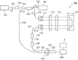
- the ophthalmologic photographing apparatus 1 includes a fundus camera unit 2, an OCT unit 100, and an arithmetic control unit 200.
- the retinal camera unit 2 has almost the same optical system as a conventional retinal camera.
- the OCT unit 100 is provided with an optical system for executing OCT.
- the arithmetic control unit 200 includes a computer that executes various arithmetic processes and control processes.
- the fundus camera unit 2 shown in FIG. 1 is provided with an optical system for obtaining a two-dimensional image (fundus image) representing the surface form of the fundus oculi Ef of the eye E to be examined.
- the fundus image includes an observation image and a captured image.
- the observation image is, for example, a monochrome moving image formed at a predetermined frame rate using near infrared light.
- the captured image may be, for example, a color image obtained by flashing visible light, or a monochrome still image using near infrared light or visible light as illumination light.
- the fundus camera unit 2 may be configured to be able to acquire images other than these, such as a fluorescein fluorescent image, an indocyanine green fluorescent image, a spontaneous fluorescent image, and the like.
- the fundus camera unit 2 is provided with a chin rest and a forehead for supporting the subject's face. Further, the fundus camera unit 2 is provided with an illumination optical system 10 and a photographing optical system 30.
- the illumination optical system 10 irradiates the fundus oculi Ef with illumination light.
- the photographing optical system 30 guides the fundus reflection light of the illumination light to an imaging device (CCD image sensor (sometimes simply referred to as a CCD) 35, 38).
- the imaging optical system 30 guides the measurement light from the OCT unit 100 to the eye E and guides the measurement light passing through the eye E to the OCT unit 100.
- the observation light source 11 of the illumination optical system 10 includes, for example, a halogen lamp or an LED (Light Emitting Diode).
- the light (observation illumination light) output from the observation light source 11 is reflected by the reflection mirror 12 having a curved reflection surface, passes through the condensing lens 13, passes through the visible cut filter 14, and is converted into near infrared light. Become. Further, the observation illumination light is once converged in the vicinity of the photographing light source 15, reflected by the mirror 16, and passes through the relay lenses 17 and 18, the diaphragm 19 and the relay lens 20. Then, the observation illumination light is reflected at the peripheral portion (region around the hole portion) of the aperture mirror 21, passes through the dichroic mirror 46, and is refracted by the objective lens 22 to illuminate the fundus oculi Ef.
- the fundus reflection light of the observation illumination light is refracted by the objective lens 22, passes through the dichroic mirror 46, passes through the hole formed in the central region of the perforated mirror 21, passes through the dichroic mirror 55, and is a focusing lens. It is reflected by the mirror 32 via 31. Further, the fundus reflection light passes through the half mirror 33A, is reflected by the dichroic mirror 33, and forms an image on the light receiving surface of the CCD image sensor 35 by the condenser lens.
- the CCD image sensor 35 detects fundus reflected light at a predetermined frame rate, for example. On the display device 3, an image (observation image) based on fundus reflection light detected by the CCD image sensor 35 is displayed.
- an observation image based on fundus reflection light detected by the CCD image sensor 35 is displayed.
- the imaging light source 15 is constituted by, for example, a xenon lamp or an LED.
- the light (imaging illumination light) output from the imaging light source 15 is applied to the fundus oculi Ef through the same path as the observation illumination light.
- the fundus reflection light of the imaging illumination light is guided to the dichroic mirror 33 through the same path as that of the observation illumination light, passes through the dichroic mirror 33, is reflected by the mirror 36, and is reflected by the condenser lens 37 of the CCD image sensor 38.
- An image is formed on the light receiving surface.
- On the display device 3 an image (captured image) based on fundus reflection light detected by the CCD image sensor 38 is displayed.
- the display device 3 that displays the observation image and the display device 3 that displays the captured image may be the same or different.
- an infrared captured image is displayed. It is also possible to use an LED as a photographing light source.
- the LCD (Liquid Crystal Display) 39 displays a fixation target and an eyesight measurement index.
- the fixation target is an index for fixing the eye E to be examined, and is used at the time of fundus photographing or OCT measurement.
- a part of the light output from the LCD 39 is reflected by the half mirror 33A, reflected by the mirror 32, passes through the focusing lens 31 and the dichroic mirror 55, passes through the hole of the perforated mirror 21, and then reaches the dichroic.
- the light passes through the mirror 46, is refracted by the objective lens 22, and is projected onto the fundus oculi Ef.
- the fixation position of the eye E can be changed by changing the display position of the fixation target on the screen of the LCD 39.
- As the fixation position of the eye E for example, as in a conventional fundus camera, a position for acquiring an image centered on the macular of the fundus oculi Ef, a position for acquiring an image centered on the optic nerve head, And a position for acquiring an image centered on the fundus center between the macula and the optic disc. It is also possible to arbitrarily change the display position of the fixation target.
- the fundus camera unit 2 is provided with an alignment optical system 50 and a focus optical system 60 as in the conventional fundus camera.
- the alignment optical system 50 generates an index (alignment index) for performing alignment (alignment) of the apparatus optical system with respect to the eye E.
- the focus optical system 60 generates an index (split index) for focusing on the eye E to be examined.
- the light (alignment light) output from the LED 51 of the alignment optical system 50 is reflected by the dichroic mirror 55 via the apertures 52 and 53 and the relay lens 54, passes through the hole of the perforated mirror 21, and reaches the dichroic mirror 46. And is projected onto the cornea of the eye E by the objective lens 22.
- the corneal reflection light of the alignment light passes through the objective lens 22, the dichroic mirror 46 and the hole, part of which passes through the dichroic mirror 55, passes through the focusing lens 31, is reflected by the mirror 32, and is half mirror
- the light passes through 33A, is reflected by the dichroic mirror 33, and is projected onto the light receiving surface of the CCD image sensor 35 by the condenser lens.
- the light reception image (alignment index) by the CCD image sensor 35 is displayed on the display device 3 together with the observation image.
- the user performs alignment by performing the same operation as that of a conventional fundus camera. Further, the arithmetic control unit 200 may perform alignment by analyzing the position of the alignment index and moving the optical system (auto-alignment function).
- the reflecting surface of the reflecting rod 67 is obliquely provided on the optical path of the illumination optical system 10.
- the light (focus light) output from the LED 61 of the focus optical system 60 passes through the relay lens 62, is separated into two light beams by the split indicator plate 63, passes through the two-hole aperture 64, and is reflected by the mirror 65, The light is focused on the reflecting surface of the reflecting bar 67 by the condenser lens 66 and reflected. Further, the focus light passes through the relay lens 20, is reflected by the perforated mirror 21, passes through the dichroic mirror 46, is refracted by the objective lens 22, and is projected onto the fundus oculi Ef.
- the fundus reflection light of the focus light is detected by the CCD image sensor 35 through the same path as the corneal reflection light of the alignment light.
- a light reception image (split index) by the CCD image sensor 35 is displayed on the display device 3 together with the observation image.
- the arithmetic and control unit 200 analyzes the position of the split index and moves the focusing lens 31 and the focus optical system 60 to perform focusing as in the conventional case (autofocus function). Alternatively, focusing may be performed manually while visually checking the split indicator.
- the dichroic mirror 46 branches the optical path for OCT from the optical path for fundus photography.
- the dichroic mirror 46 reflects light in a wavelength band used for OCT and transmits light for fundus photographing.
- a collimator lens unit 40 in order from the OCT unit 100 side, a collimator lens unit 40, an optical path length changing unit 41, a variable cross cylinder lens (hereinafter referred to as a VCC lens) 47, an optical scanner 42, and a focusing lens 43.
- a mirror 44 and a relay lens 45 are provided.
- the optical path length changing unit 41 is movable in the direction of the arrow shown in FIG. 1, and changes the optical path length of the optical path for OCT. This change in the optical path length is used for correcting the optical path length according to the axial length of the eye E or adjusting the interference state.
- the optical path length changing unit 41 includes, for example, a corner cube and a mechanism for moving the corner cube.
- the optical scanner 42 is disposed at a position optically conjugate with the pupil of the eye E to be examined.
- the optical scanner 42 changes the traveling direction of the light (measurement light LS) passing through the optical path for OCT. Thereby, the eye E can be scanned with the measurement light LS.
- the optical scanner 42 includes, for example, a galvanometer mirror that scans the measurement light LS in the x direction, a galvanometer mirror that scans in the y direction, and a mechanism that drives these independently. Thereby, the measurement light LS can be scanned in an arbitrary direction on the xy plane.
- the OCT unit 100 is provided with an optical system for acquiring an OCT image of the eye E.
- This optical system has the same configuration as a conventional swept source type OCT apparatus. That is, this optical system divides the light from the wavelength scanning type (wavelength sweep type) light source into the measurement light and the reference light, and returns the return light of the measurement light from the eye E and the reference light via the reference light path.
- An interference optical system that generates interference light by causing interference and detects the interference light.
- the detection result (detection signal) of the interference light by the interference optical system is a signal indicating the spectrum of the interference light and is sent to the arithmetic control unit 200.
- the light source unit 101 is configured to include a wavelength scanning type (wavelength sweep type) light source capable of scanning (sweeping) the wavelength of emitted light, as in a general swept source type OCT apparatus.
- the light source unit 101 temporally changes the output wavelength in the near-infrared wavelength band that cannot be visually recognized by the human eye.
- the light L0 output from the light source unit 101 is guided to the polarization controller 103 by the optical fiber 102 and its polarization state is adjusted.
- the polarization controller 103 adjusts the polarization state of the light L0 guided through the optical fiber 102, for example, by applying stress from the outside to the looped optical fiber 102.
- the light L0 whose polarization state has been adjusted by the polarization controller 103 is guided to the fiber coupler 105 by the optical fiber 104 and split into the measurement light LS and the reference light LR.
- the reference light LR is guided to the collimator 111 by the optical fiber 110 to become a parallel light beam.
- the reference light LR that has become a parallel light beam is guided to the corner cube 114 via the optical path length correction member 112 and the dispersion compensation member 113.
- the optical path length correction member 112 functions as a delay unit for matching the optical path length (optical distance) of the reference light LR and the optical path length of the measurement light LS.
- the dispersion compensation member 113 functions as a dispersion compensation means for matching the dispersion characteristics between the reference light LR and the measurement light LS.
- the corner cube 114 folds the traveling direction of the reference light LR that has become a parallel light beam by the collimator 111 in the reverse direction.
- the optical path of the reference light LR incident on the corner cube 114 and the optical path of the reference light LR emitted from the corner cube 114 are parallel.
- the corner cube 114 is movable in a direction along the incident optical path and the outgoing optical path of the reference light LR. By this movement, the length of the optical path of the reference light LR is changed.
- Both corner cubes 114 for changing the length of the arm) are provided, but either one of them may be provided. It is also possible to change the difference between the measurement optical path length and the reference optical path length using optical members other than these.
- the reference light LR that has passed through the corner cube 114 passes through the dispersion compensation member 113 and the optical path length correction member 112, is converted from a parallel light beam to a focused light beam by the collimator 116, enters the optical fiber 117, and is guided to the polarization controller 118. Accordingly, the polarization state of the reference light LR is adjusted.
- the polarization controller 118 has the same configuration as the polarization controller 103, for example.
- the reference light LR whose polarization state is adjusted by the polarization controller 118 is guided to the attenuator 120 by the optical fiber 119, and the light quantity is adjusted under the control of the arithmetic control unit 200.
- the reference light LR whose light amount has been adjusted by the attenuator 120 is guided to the fiber coupler 122 by the optical fiber 121.
- the measurement light LS generated by the fiber coupler 105 is guided by the optical fiber 127 and converted into a parallel light beam by the collimator lens unit 40.
- the measurement light LS converted into a parallel light beam reaches the dichroic mirror 46 via the optical path length changing unit 41, the optical scanner 42, the focusing lens 43, the mirror 44, and the relay lens 45.
- the measurement light LS is reflected by the dichroic mirror 46, refracted by the objective lens 22, and irradiated to the eye E.
- the measurement light LS is scattered (including reflection) at various depth positions of the eye E.
- the return light of the measurement light LS including such backscattered light travels in the reverse direction on the same path as the forward path, is guided to the fiber coupler 105, and reaches the fiber coupler 122 via the optical fiber 128.
- the fiber coupler 122 combines (interferences) the measurement light LS incident through the optical fiber 128 and the reference light LR incident through the optical fiber 121 to generate interference light.
- the fiber coupler 122 branches the interference light between the measurement light LS and the reference light LR at a predetermined branching ratio (for example, 1: 1), thereby generating a pair of interference lights LC.
- the pair of interference lights LC emitted from the fiber coupler 122 are guided to the detector 125 by optical fibers 123 and 124, respectively.
- the detector 125 is, for example, a balanced photodiode (Balanced Photo Diode) that has a pair of photodetectors that respectively detect a pair of interference lights LC and outputs a difference between detection results obtained by these.
- the detector 125 sends the detection result (detection signal) to the arithmetic control unit 200.
- the arithmetic control unit 200 performs, for example, Fourier transform or the like on the spectrum distribution based on the detection result obtained by the detector 125 for each series of wavelength scans (for each A line), thereby obtaining the reflection intensity profile in each A line. Form.
- the arithmetic control unit 200 forms image data by imaging the reflection intensity profile of each A line.
- a Michelson type interference optical system is employed, but any type of interference optical system such as a Mach-Zehnder type can be employed.
- the configuration of the arithmetic control unit 200 will be described.
- the arithmetic control unit 200 analyzes the detection signal input from the detector 125 and forms an OCT image of the eye E.
- the arithmetic processing for this is the same as that of a conventional swept source type OCT apparatus.
- the arithmetic control unit 200 controls each part of the fundus camera unit 2, the display device 3, and the OCT unit 100. For example, the arithmetic control unit 200 displays an OCT image of the eye E on the display device 3.
- the arithmetic control unit 200 controls the operation of the observation light source 11, the imaging light source 15 and the LEDs 51 and 61, the operation control of the LCD 39, the movement control of the focusing lenses 31 and 43, and the reflector 67. Movement control, movement control of the focus optical system 60, movement control of the optical path length changing unit 41, operation control of the optical scanner 42, and the like are performed.
- the arithmetic control unit 200 controls the operation of the light source unit 101, the movement control of the corner cube 114, the operation control of the detector 125, the operation control of the attenuator 120, and the operations of the polarization controllers 103 and 118. Control and so on.
- the arithmetic control unit 200 includes, for example, a microprocessor, a RAM (Random Access Memory), a ROM (Read Only Memory), a hard disk drive, a communication interface, and the like, as in a conventional computer.
- a computer program for controlling the ophthalmologic photographing apparatus 1 is stored in a storage device such as a hard disk drive.
- the arithmetic control unit 200 may include various circuit boards, for example, a circuit board for forming an OCT image.
- the arithmetic control unit 200 may include an operation device (input device) such as a keyboard and a mouse, and a display device such as an LCD.
- the fundus camera unit 2, the display device 3, the OCT unit 100, and the calculation control unit 200 may be configured integrally (that is, in a single housing) or separated into two or more cases. It may be.
- Control system The configuration of the control system of the ophthalmologic photographing apparatus 1 will be described with reference to FIG. In FIG. 3, some components of the ophthalmologic photographing apparatus 1 are omitted, and components particularly necessary for explaining this embodiment are selectively shown.
- the control system of the ophthalmologic photographing apparatus 1 is configured around the control unit 210.
- the controller 210 includes, for example, a microprocessor, RAM, ROM, hard disk drive, communication interface, and the like.
- the control unit 210 is provided with a main control unit 211 and a storage unit 212.
- the main control unit 211 performs the various controls described above.
- the main control unit 211 includes the imaging focus drive unit 31A, the CCD image sensors 35 and 38, the LCD 39, the optical path length change unit 41, the optical scanner 42, and the OCT focus drive of the fundus camera unit 2.
- the unit 43A, the light source unit 101 of the OCT unit 100, the reference driving unit 114A, the detector 125, and the like are controlled.
- the photographing focusing drive unit 31A moves the focusing lens 31 in the optical axis direction. Thereby, the focus position of the photographic optical system 30 is changed.
- the main control unit 211 can control an optical system drive unit (not shown) to move the optical system provided in the fundus camera unit 2 three-dimensionally. This control is used in alignment and tracking. Tracking refers to moving the apparatus optical system in accordance with the movement of the eye E. When tracking is performed, alignment and focusing are performed in advance. Tracking maintains a suitable positional relationship in which alignment and focus are achieved by moving the apparatus optical system in real time according to the position and orientation of the eye E based on an image obtained by taking a moving image of the eye E. It is a function.
- the OCT focusing drive unit 43A moves the focusing lens 43 along the optical axis of the measurement optical path. Thereby, the focus position of the measurement light LS is changed.
- the focus position of the measurement light LS corresponds to the depth position (z position) of the beam waist of the measurement light LS.
- the reference driving unit 114A moves the corner cube 114 provided in the reference optical path. Thereby, the length of the reference optical path is changed. As described above, the optical path length changing unit 41 and only one of the corner cube 114 and the reference driving unit 114A may be provided.
- the main control unit 211 includes a measurement control unit 2111 and a display control unit 2112.
- the measurement control unit 2111 controls OCT measurement by the fundus camera unit 2 and the OCT unit 100.
- the measurement control unit 2111 includes a condition relating to scanning of the measurement light LS (scan condition), a condition relating to the focus of the measurement light LS (focus condition), and a condition relating to an interference state between the measurement light LS and the reference light LR (interference condition).
- the scan condition includes a scan pattern related to the control of the optical scanner 42, a scan interval, a scanable range, and the like.
- the scan condition includes selection of a scan pattern, a scan position and a scan direction of the selected scan pattern, a scan pattern shape, and the like.
- the scan pattern is a condition that represents the shape of the scan, and specific examples include a line scan in a line segment, a circle scan in a circle shape, a raster scan, a cross scan, and a radial scan.
- the scan interval includes an interval between adjacent scan patterns, an interval between scan areas described later, and an interval between adjacent scan lines in the scan pattern in the case of multiline cross.
- the scannable range is uniquely determined by the hardware configuration of the ophthalmologic photographing apparatus 1, but the position can be controlled.
- the focus condition includes a focus position of the measurement light LS related to control of the focus lens 43 (OCT focus drive unit 43A) and the like.
- the interference condition relates to the control of the focusing lens 43 (OCT focusing driving unit 43A), the corner cube 114 (reference driving unit 114A), the polarization controller 118, and the attenuator 120.
- the fixation condition includes a projection position of a fixation target related to the control of the LCD 39.
- the measurement control unit 2111 executes control based on the set conditions. Note that the conditions controlled by the measurement controller 2111 are not limited to these, and include diopter correction according to the diopter of the eye E, for example.
- the display control unit 2112 displays various information on the display unit 241.
- the display control unit 2112 is controlled by the measurement control unit 2111 on the observation image (moving image) of the eye E generated based on the fundus reflection light detected by the CCD image sensor 35 (or the CCD image sensor 38). Scan pattern images corresponding to the scan patterns can be displayed on the display unit 241 in a superimposed manner.
- the storage unit 212 stores various data. Examples of the data stored in the storage unit 212 include OCT image image data, fundus image data, and examined eye information.
- the eye information includes information about the subject such as patient ID and name, and information about the eye such as left / right eye identification information.
- the storage unit 212 stores various programs and data for operating the ophthalmologic photographing apparatus 1.
- the image forming unit 220 forms image data of a cross-sectional image of the fundus oculi Ef based on the detection signal from the detector 125. That is, the image forming unit 220 forms image data of the eye E based on the detection result of the interference light LC by the interference optical system.
- This process includes processes such as noise removal (noise reduction), filter processing, and FFT (Fast Fourier Transform), as in the case of the conventional swept source type OCT.
- the image data acquired in this way is a data set including a group of image data formed by imaging reflection intensity profiles in a plurality of A lines (paths of the measurement light LS in the eye E). is there.
- the image forming unit 220 includes, for example, the circuit board described above.
- image data and “image” based thereon may be identified.
- the part of the eye E to be examined and the image thereof may be identified.
- the data processing unit 230 performs various types of data processing (image processing) and analysis processing on the OCT image formed by the image forming unit 220. For example, the data processing unit 230 executes correction processing such as image brightness correction and dispersion correction. Further, the data processing unit 230 performs various types of image processing and analysis processing on the image (fundus image, anterior eye image, etc.) obtained by the fundus camera unit 2.
- the data processing unit 230 can form volume data (voxel data) of the eye E by performing known image processing such as interpolation processing for interpolating pixels between cross-sectional images.
- image processing such as interpolation processing for interpolating pixels between cross-sectional images.
- the data processing unit 230 performs a rendering process on the volume data to form a pseudo three-dimensional image when viewed from a specific viewing direction.
- the data processing unit 230 can perform alignment between the fundus image and the OCT image.
- the optical axis of the imaging optical system 30 is used to (substantially) simultaneously acquire the fundus image and the OCT image. Can be aligned with reference to.
- the front image obtained by projecting at least a part of the image area corresponding to the fundus oculi Ef of the OCT image onto the xy plane is aligned with the fundus image. By doing so, it is possible to align the OCT image and the fundus image.
- This alignment method is applicable even when the fundus image acquisition optical system and the OCT optical system are not coaxial. Even if both optical systems are not coaxial, if the relative positional relationship between both optical systems is known, the same alignment as in the coaxial case is executed with reference to this relative positional relationship. It is possible.
- the data processing unit 230 that functions as described above includes, for example, a microprocessor, a RAM, a ROM, a hard disk drive, a circuit board, and the like.
- a storage device such as a hard disk drive, a computer program for causing the microprocessor to execute the above functions is stored in advance.
- the user interface 240 includes a display unit 241 and an operation unit 242.
- the display unit 241 includes the display device of the arithmetic control unit 200 and the display device 3 described above.
- the operation unit 242 includes the operation device of the arithmetic control unit 200 described above.
- the operation unit 242 may include various buttons and keys provided on the housing of the ophthalmologic photographing apparatus 1 or outside. Further, the display unit 241 may include various display devices such as a touch panel provided in the housing of the fundus camera unit 2.
- the display unit 241 and the operation unit 242 do not need to be configured as individual devices.
- a device in which a display function and an operation function are integrated such as a touch panel
- the operation unit 242 includes the touch panel and a computer program.
- the operation content for the operation unit 242 is input to the control unit 210 as an electrical signal. Further, operations and information input may be performed using the graphical user interface (GUI) displayed on the display unit 241 and the operation unit 242.
- GUI graphical user interface
- the ophthalmologic imaging apparatus 1 can store the scan pattern applied to the OCT measurement, and can apply the stored scan pattern to the subsequent OCT measurement.
- the operation unit 242 is used for inputting the identification information of the subject.
- the storage unit 212 stores operation information including scan information representing a scan pattern applied to the eye E in association with identification information.
- the measurement control unit 2111 reads scan information associated with the newly input identification information from the storage unit 212.
- the measurement control unit 2111 applies the scan pattern represented by the read scan information to cause the fundus camera unit 2 and the OCT unit 100 to perform OCT measurement.
- the storage unit 212 may store scan information including information indicating a position where the scan pattern is applied to the eye E.
- the measurement control unit 2111 reads scan information associated with the newly input identification information from the storage unit 212, and the scan pattern represented by the read scan information is the eye E to be examined represented by the scan information.
- the fundus camera unit 2 and the OCT unit 100 are controlled so as to be applied to the position.
- the scan information may include a fixation position or a position in the observation image.
- the scan pattern applied in the past OCT measurement can be applied to the subsequent measurement and the follow-up observation of the attention site can be performed with high accuracy.
- the LCD 39 is an example of a “fixation target projection unit” according to this embodiment.
- the fundus camera unit 2 and the OCT unit 100 are examples of the “measurement unit” according to this embodiment.
- the CCD image sensor 35 or the CCD image sensor 38 is an example of a “photographing unit” according to this embodiment.
- the “imaging unit” according to this embodiment may further include an optical system for generating fundus reflection light detected by the CCD image sensor 35 or the CCD image sensor 38.
- the display unit 241 is an example of a “display unit” according to this embodiment.
- the operation unit 242 is an example of an “operation unit” according to this embodiment.
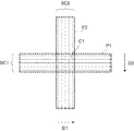
- FIG. 4 is an explanatory diagram of “5-line cross” according to this embodiment.
- FIG. 4 schematically illustrates an example of a “5-line cross” scan pattern.
- the “5-line cross” includes five first scan line groups SC1 parallel to each other extending in the first direction D1 (for example, the x direction) and a second direction D2 (for example, the y direction) orthogonal to the first direction D1. Is a scan pattern arranged so that five second scan line groups SC2 extending in parallel with each other intersect each other.
- the “5-line cross” forms a first scan region P1 scanned by the first scan line group SC1 and a second scan region P2 scanned by the second scan line group SC2.
- the intersection region C1 between the first scan region P1 and the second scan region P2 overlaps with, for example, a region of interest of the fundus oculi Ef (the macula (fovea), the optic disc, an arbitrary position between the macula and the optic disc), etc. Placed in.
- the arrows of the line-shaped scan lines constituting each scan line group represent the scan direction of the scan line
- the start point and end point of the scan line represent the scan start position and the scan end position of the scan line
- the length of the scan line This represents the scan length of the scan line. That is, the scan line shown in FIG. 4 represents the scan position and the scan direction of the scan along the scan line.
- the boundary on the scan start position side of the first scan region P1 is defined by the scan start positions of five scan lines.
- the boundary on the scan end position side of the first scan region P1 is defined by the scan end positions of the five scan lines.
- the boundary of the first scan region P1 parallel to the first direction D1 is the two scan lines arranged on the outermost side among the five scan lines arranged side by side in the second direction D2, or the two scan lines. It is defined by a position further away from the scan line by a predetermined distance.
- the boundary of the second scan region P2 is also defined similarly to the first scan region P1.
- FIG. 4 shows an example in which the first scan region P1 (first scan line group SC1) is arranged so as to be orthogonal to the second scan region P2 (second scan line group SC2).
- P1 should just be arrange
- FIG. 4 shows an example in which each of the first scan region P1 and the second scan region P2 is scanned by five scan lines, but is not limited to the number of scan lines.
- at least one of the first scan area P1 and the second scan area P2 may be an area scanned by one or three scan lines.
- 5-line cross is an example of a scan pattern having two scan areas corresponding to two or more scan lines representing a scan position and a scan direction and arranged so that at least two intersect each other. It is also possible to apply to this embodiment a scan pattern arranged such that three or more scan regions intersect like a scan.
- a first scan along at least one scan line constituting the first scan line group SC1 and a second scan along at least one scan line constituting the second scan line group SC2 are alternately executed. Is done. Note that “execution of the first scan and the second scan alternately” is not limited to the case where the first scan of one time and the second scan of one time are executed alternately. This is a concept including a case where a scan and one or more second scans are alternately executed. Further, the scan line group in each scan area is scanned cyclically in a predetermined order.
- the first scan and the second scan can be performed simultaneously.
- the relative position between the first scan region P1 and the second scan region P2 can be changed automatically or manually.
- the data processing unit 230 analyzes the observation image of the eye E to identify the position of a specific part (macular, fovea, optic nerve head, blood vessel, diseased part, etc.), and this identification
- the scan position is set by changing the relative position between the first scan region P1 and the second scan region P2 so as to pass through the site determined by the site or the specific site.
- the scan position is set so that the intersection region C1 between the first scan region P1 and the second scan region P2 matches the specific part by the above analysis.
- the relative position is changed by moving each scan area in a predetermined direction.
- the moving direction of the first scan region P1 is the first direction D1 or the opposite direction.
- the moving direction of the second scan region P2 is the second direction D2 or the opposite direction.
- the movement of the scan area includes at least one of parallel movement and rotational movement.
- the measurement control unit 2111 sets the scan line of each scan area in the same direction (the same amount) according to the change contents (movement direction and movement amount) of the scan position. This is executed by changing the setting for controlling the optical scanner 42 so as to be moved by a distance.
- the user designates the scan area to be moved using the user interface 240 and moves the designated scan area.
- the relative position is manually changed.
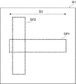
- FIG. 5 schematically shows an example of the screen of the display unit 241 for changing the relative position between the first scan region P1 and the second scan region P2.
- the user selects a scan pattern using the user interface 240 by a known method.
- the display control unit 2112 superimposes on the moving image of the eye E generated based on the fundus reflection light detected by the CCD image sensor 35, and displays the display unit Scan pattern images SP1 and SP2 corresponding to the scan pattern of “5-line cross” are displayed in accordance with the initial position and the initial direction in the display area 241.
- the display control unit 2112 superimposes on the moving image of the eye E based on the fundus reflection light detected by the CCD image sensor 35 and matches the previous scan position and scan direction in the display area of the display unit 241.
- Scan pattern images SP1 and SP2 may be displayed.
- the scan pattern images SP1 and SP2 are images displayed on the display unit 241 corresponding to two or more scan lines representing the scan position and the scan direction (in this embodiment, five scan lines in each of the two directions). It is an image arranged so that at least two intersect.
- the first scan region P1 and the scan pattern image SP1 displayed on the display unit 241 corresponding thereto may be identified.
- the second scan region P2 and the scan pattern image SP2 displayed on the display unit 241 corresponding thereto may be identified.
- the scan pattern image includes an image SP1 representing the boundary of the first scan region P1 constituting the scan pattern and an image SP2 representing the boundary of the second scan region P2 constituting the scan pattern. It is.
- the scan pattern image includes, for example, a scan line image SL1 corresponding to the first scan line group SC1 in the first scan region P1, and a scan line corresponding to the second scan line group SC2 in the second scan region P2.
- the image SL2 may also be used (FIG. 5).
- the scan pattern image may be an image of the vicinity of the scan start position and the vicinity of the scan end position of the scan line in each scan region so as not to hinder observation of the target region.
- the scan pattern image may further include an image representing the intersecting region C1.
- both the images SP ⁇ b> 1 and SP ⁇ b> 2 and the images SL ⁇ b> 1 and SL ⁇ b> 2 are illustrated as scan pattern images, but only one of them may be displayed on the display unit 241.
- the display control unit 2112 also displays a display range R1 corresponding to the scanable range of the ophthalmologic photographing apparatus 1 within the display region of the display unit 241 on which the scan pattern images SP1 and SP2 are displayed. It can be displayed. Thereby, it becomes easy to grasp the movable range of the scan pattern image SP1 (first scan region P1) and the scan pattern image SP2 (second scan region P2). Therefore, the user can change the relative positions of the scan pattern images SP1 and SP2 while confirming the movable range.
- the scanable range and the display range R1 displayed on the display unit 241 corresponding thereto may be identified.
- the operation unit 242 receives various operations by the user.
- the operation unit 242 designates one of the scan pattern images SP1 and SP2 (first designation operation) and a movement operation (first operation) for translating or rotating the scan pattern image designated by the designation operation. 1 movement operation).
- the designation operation is performed, for example, by selecting from scan pattern image groups corresponding to movable scan area groups.
- the moving operation is performed, for example, by specifying the moving direction and moving amount of the scan pattern image specified by the specifying operation.
- the touch panel functions as the display unit 241 and the operation unit 242
- the screen of the display unit 241 functions as an operation screen.
- the designation operation is performed by, for example, a touch operation on a position in the operation screen associated with a desired scan pattern image from the movable scan pattern image group.
- the moving operation is performed, for example, by dragging the moving direction and moving amount of the scan pattern image specified by the specifying operation with respect to the operation screen.
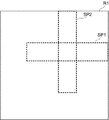
- the measurement control unit 2111 main control unit 2111 performs the first scan based on the operation content on the operation unit 242.
- the region P1 is specified.
- the measurement control unit 2111 is based on the operation content on the operation unit 242. Then, the position of the first scan region P1 moved by a predetermined movement amount in the movement direction D4 is obtained.
- the display control unit 2112 displays the scan pattern image SP1 at a display position corresponding to the position of the first scan region P1 obtained by the measurement control unit 2111 (state shown in FIG. 6A). Accordingly, the display control unit 2112 can change the display position of the scan pattern image corresponding to the scan area in accordance with the movement operation.
- the moving direction D4 is illustrated as a direction parallel to the second direction D2, but may be any direction along the surface of the fundus oculi Ef.
- the measurement control unit 2111 determines the optical scanner based on the scan lines in the scan areas P1 and P2 corresponding to the scan pattern images SP1 and SP2 after the relative position is changed. By controlling the scanning position by 42, the fundus camera unit 2 and the OCT unit 100 are caused to perform OCT measurement.
- the measurement control unit 2111 performs the second scan based on the operation content on the operation unit 242.
- the region P2 is specified.
- the measurement control unit 2111 is based on the operation content on the operation unit 242. Then, the position of the second scan area P2 moved by a predetermined movement amount in the movement direction D3 is obtained.
- the display control unit 2112 displays the scan pattern image SP2 at a display position corresponding to the position of the second scan region P2 obtained by the measurement control unit 2111 (state shown in FIG. 6B).
- the moving direction D3 is illustrated as a direction parallel to the first direction D1, but may be an arbitrary direction along the surface of the fundus oculi Ef.
- the measurement control unit 2111 uses the optical scanner based on the scan lines in the scan areas P1 and P2 corresponding to the scan pattern images SP1 and SP2 after the relative position is changed. By controlling the scanning position by 42, the fundus camera unit 2 and the OCT unit 100 are caused to perform OCT measurement.
- the scan pattern images SP1 and SP2 are rotationally moved with reference to an arbitrary position within the display range R1 corresponding to the scannable range, similar to the above-described parallel movement. It is also possible to make it.
- the rotational movement for example, the user performs an operation of specifying the rotation center position, an operation of specifying the scan pattern image to be rotated, and an operation of rotating the specified scan pattern image by a desired angle.
- a configuration in which the center position of the designated scan pattern image is set as the center of rotation a configuration in which the center position of the intersection area of the scan pattern image is set as the center of rotation, or a predetermined target region (fovea etc.) It is possible to apply a configuration set as the rotation center.
- the user can also move the scan pattern images SP1 and SP2 (the first scan region P1 and the second scan region P2) integrally using the user interface 240.
- the processing in this case is executed as follows, for example.
- the operation unit 242 designates the scan pattern images SP1 and SP2 by the user (second designation operation), and a movement operation (second movement operation) for translating or rotating the scan pattern image designated by the designation operation. ) And accept.
- the designation operation is performed, for example, by designating an intersecting region where at least two of two or more scan pattern images intersect.
- the moving operation is performed, for example, by specifying the moving direction and moving amount of the scan pattern images SP1 and SP2 specified by the specifying operation.
- the touch panel functions as the display unit 241 and the operation unit 242
- the designation operation is performed in a screen different from the positions of the scan pattern images SP1 and SP2 displayed in the display area of the display unit 241 (in the moving image), for example. This is performed by a touch operation on the position.
- the designation operation may be performed, for example, by a touch operation on an intersecting region where at least two of two or more scan pattern images intersect.
- the movement operation is performed by, for example, a drag operation on the position specified by the touch
- the measurement control unit 2111 (main control unit 211) operates the operation unit 242.
- the first scan area P1 and the second scan area P2 are specified based on the contents.
- the measurement control unit 2111 displays the scan pattern image SP1 at a display position corresponding to the position of the first scan region P1 obtained by the measurement control unit 2111, and the position of the second scan region P2 obtained by the measurement control unit 2111.
- the scan pattern image SP2 is displayed at the display position corresponding to (state shown in FIG. 6C).
- the measurement control unit 2111 is based on the scan lines in the scan areas P1 and P2 corresponding to the scan pattern images SP1 and SP2 after the movement.
- the fundus camera unit 2 and the OCT unit 100 are caused to execute OCT measurement.
- the user integrally moves at least a part of the two or more scan pattern images corresponding to the two or more scan areas. Is possible.
- the movement of the scan pattern image may be limited to a scannable range of the ophthalmologic photographing apparatus 1.
- the measurement control unit 2111 obtains the position of the scan pattern image moved as described above, and the entire scan pattern image after moving to the obtained position is within the display range corresponding to the scanable range. It is determined whether it is included in. When it is determined that the entire scan pattern image after movement is not included in the display range, the measurement control unit 2111 performs the above movement so that the entire scan pattern image after movement falls within the display range. The position of the scan pattern image on which the operation has been performed is obtained. Accordingly, the display control unit 2112 can change the display positions of the scan pattern images SP1 and SP2 within the display range R1 of the display unit 241 corresponding to the scannable range.
- the scan pattern image can be moved as follows. is there.
- FIG. 7 A first operation example when a scan pattern image movement request is made will be described with further reference to FIG. 7, the same parts as those in FIG.
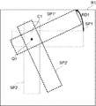
- a movement request for the scan pattern image SP1 that exceeds the scanable range (display range R1) of the movement amount d3 (first movement amount) in the movement direction D3 (first movement direction) uses the operation unit 242.
- the measurement control unit 2111 obtains a position where the scan pattern image SP1 comes into contact with the edge of the scannable range, and moves from the contact position in the direction D3 ′ (second movement direction) opposite to the movement direction D3.
- the movement position moved by the amount d3 is obtained.
- the display control unit 2112 displays the moved scan pattern image SP1 ′ at the display position of the display unit 241 corresponding to the movement position obtained by the measurement control unit 2111 (state shown in FIG. 7).
- the measurement control unit 2111 scans in the movement path. A position where the pattern image SP2 contacts the edge of the scannable range is obtained, and a movement position moved by the movement amount d4 from the contact position in the direction D4 ′ opposite to the movement direction D4 is obtained.
- the display control unit 2112 displays the moved scan pattern image SP2 ′ at the display position of the display unit 241 corresponding to the movement position obtained by the measurement control unit 2111 (state shown in FIG. 7).
- the display control unit 2112 changes the display position of the scan pattern image in contact with the edge of the scannable range.
- the first movement amount can be changed in the second movement direction, which is the opposite direction of the first movement direction.
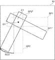
- FIGS. 8A and 8B show an example of operation when a rotational movement request is made with reference to the position Q1 in the intersecting region C1, and the same parts as in FIG. To do.
- the measurement control unit 2111 As shown, the position (contact position) at which the scan pattern image SP1 contacts the edge of the scannable range is obtained.
- the display control unit 2112 displays the scan pattern image SP1 ′ after rotation at the display position of the display unit 241 corresponding to the contact position obtained by the measurement control unit 2111.
- the display control unit 2112 displays the rotated scan pattern image SP2 ′ at the display position of the display unit 241 corresponding to the contact position obtained by the measurement control unit 2111 (state shown in FIG. 8A).
- the measurement control unit 2111 As shown in FIG. 8B, the position (contact position) where the scan pattern image SP2 contacts the edge of the scannable range is obtained.
- the display control unit 2112 displays the rotated scan pattern image SP2 ′′ at the display position of the display unit 241 corresponding to the contact position obtained by the measurement control unit 2111.
- the display control unit 2112 displays the rotated scan pattern image SP1 ′′ at the display position of the display unit 241 corresponding to the contact position obtained by the measurement control unit 2111 (state shown in FIG. 8B).
- the display control unit performs at least the movement of the display position of the scan pattern image in contact with the edge of the scannable range. Can stop at position.
- an intersection region can be placed at an arbitrary position within the scannable range, and the target region can be scanned without reducing the area of the scan region. It can be carried out.
- the scan pattern images SP1 and SP2 (the first scan region P1 and the second scan region P2) are integrally rotated has been described, but this embodiment is not limited thereto. Is not to be done.
- the scan pattern image SP1 first scan region P1
- the scan pattern image SP2 second scan region P2
- the scan pattern image SP2 may be rotated and moved while the scan pattern image SP1 is fixed.
- the movement of the display position of the scan pattern image in contact with the edge of the scannable range is stopped at the contact position as shown in FIGS. 8A and 8B. It may be.
- the scan pattern can be translated after the above rotational movement.
- FIGS. 9A and 9B A third operation example when a scan pattern image movement request is made will be described with further reference to FIGS. 9A and 9B.
- the rotated scan pattern images SP1 and SP2 correspond to the displayable range R1. Even in a state that is not parallel to the boundary, it is possible to translate at least one of the scan pattern images SP1 and SP2 (rotation is also possible).
- the intersecting region C1 of the scan pattern images SP1 and SP2 can be arranged at an arbitrary position within the arrangement range C2.
- the scan pattern is displayed in the same manner as in FIG. 8A or 8B. It is possible to move. Specifically, when a movement request for the scan pattern image SP2 exceeding the scanable range (display range R1) of the movement amount d5 in the movement direction D5 is made using the operation unit 242, the measurement control unit 2111 displays the scan pattern. The position at which the image SP2 contacts the edge of the scannable range is obtained, and the movement position moved by the movement amount d5 from the contact position in the direction D5 ′ opposite to the movement direction D5 is obtained. The display control unit 2112 displays the moved scan pattern image SP2 ′ at the display position of the display unit 241 corresponding to the movement position obtained by the measurement control unit 2111.
- the scan pattern can be moved in any direction with respect to the scan pattern in any direction, for example, a cross-sectional image along a desired site such as a straight line connecting the macula and the optic disc or a desired image It is possible to easily observe a cross-sectional image crossing the path.
- the user can change the size of the scan pattern used for the live scan and the arrangement of the scan lines in the scan area.
- the operation unit 242 accepts a size change operation for changing the size of at least a part of two or more scan pattern images by the user.
- the size of the scan pattern image includes the length, width, area, etc. of the scan pattern image in a predetermined direction.
- the size changing operation is performed, for example, by inputting a new size value for a size selected from the changeable size group, or by changing the boundary portion of the scan pattern image.
- the touch panel functions as the display unit 241 and the operation unit 242
- the size change operation is performed by designating the boundary of the scan pattern image displayed in the display area of the display unit 241 by the touch operation and dragging the boundary. This is done by being moved by operation.
- the measurement control unit 2111 obtains new display positions of the first scan region P1 and the second scan region P2 in which the size change is designated based on the operation content with respect to the operation unit 242.
- the measurement control unit 2111 may arrange the scan lines in the scan area, for example, at equal intervals according to the size of the scan area after the size change.
- the display control unit 2112 displays the scan pattern image SP1 at a display position corresponding to the position of the first scan region P1 obtained by the measurement control unit 2111, and the position of the second scan region P2 obtained by the measurement control unit 2111.
- the scan pattern image SP2 is displayed at the display position corresponding to.
- the measurement control unit 2111 controls the scan position by the optical scanner 42 based on the scan lines in the scan areas P1 and P2 corresponding to the scan pattern images SP1 and SP2 after the size change.
- the fundus camera unit 2 and the OCT unit 100 are caused to execute OCT measurement.
- the display control unit 2112 can change the display size of at least a part of two or more scan pattern images whose sizes have been changed using the operation unit 242 in accordance with the size change operation. This makes it possible to change the size of the scan pattern according to the site of interest, and the user can easily observe the desired site of interest based on the scan pattern having a suitable size within the scannable range.
- the process may be performed as described above. Specifically, it is possible to accept only the size change request within the scannable range, or to add the protruding portion to the opposite side.
- the user can use the user interface 240 to change the arrangement interval of the scan lines in the scan area.
- the operation unit 242 accepts an operation for changing the relative positions of two or more scan lines by the user.
- the change in the relative position of two or more scan lines includes a change in the interval between adjacent scan lines, a change in the scan position (scan start position or scan end position) of adjacent scan lines, and the like.
- the change in the relative position of two or more scan lines may be a concept that includes a change in scan direction.
- the operation for changing the relative position of two or more scan lines is, for example, specifying a desired scan line and moving the specified scan line while fixing the scan line adjacent to the specified scan line. Is done.
- an operation for changing the relative positions of two or more scan lines is adjacent to a touch operation for designating a desired scan line and a designated scan line.
- a drag operation for moving the designated scan line in a state in which the scan line to be fixed is fixed.
- Measurement control unit 2111 controls fundus camera unit 2 and OCT unit 100 to perform OCT measurement by controlling the scan position by optical scanner 42 based on two or more scan lines whose relative positions have been changed. As a result, the arrangement density of the scan lines can be appropriately changed, and the user can perform detailed observation according to a desired site of interest.
- FIG. 1 An example of information display is shown in FIG. In this example, a case where a scan pattern of “5-line cross” is applied will be described, but a similar display process can be executed even when another scan pattern is applied.
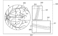
- the display screen 300 shown in FIG. 10 is displayed on the display unit 241 by the display control unit 2112.
- the display screen 300 is provided with a first moving image display area 301, a second moving image display area 302, and a front image display area 303.
- an observation image H of the fundus oculi Ef is displayed.
- the observation image H is an infrared moving image.
- the front image display area 303 further includes a scan line image SL1 corresponding to the first scan line group SC1 in the first scan area P1, and a scan line corresponding to the second scan line group SC2 in the second scan area P2.
- the image SL2 is displayed.
- the scan line images SL1 and SL2 are displayed on the observation image H.
- a display range R1 corresponding to the scannable range is displayed on the observation image H.
- the display range R1 may be displayed or may not be displayed.
- a moving image (first moving image) G1 obtained by repeatedly scanning the first scan line group SC1 in the first scan area P1 corresponding to the scan line image SL1 is displayed.
- a moving image (second moving image) G2 obtained by repeatedly scanning the second scan line group SC2 in the second scan region P2 corresponding to the scan line image SL2 is displayed.
- the display control unit 2112 first generates cross-sectional images sequentially formed by the image forming unit 220 from data obtained by the first scan at a predetermined frame rate (for example, equal to or a multiple of the repetition rate of the first scan). By displaying it in the moving image display area 301, the first moving image G1 is displayed. Similarly, the display control unit 2112 generates a cross-sectional image sequentially formed by the image forming unit 220 from data obtained by the second scan at a predetermined frame rate (for example, equal to or an integral multiple of the repetition rate of the second scan). By displaying in the second moving image display area 302, the second moving image G2 is displayed.
- a predetermined frame rate for example, equal to or a multiple of the repetition rate of the first scan.
- the first moving image display area 301 is arranged in a direction corresponding to the image SL1 of the scan line.
- the first moving image display area 301 is rectangular, and the orientations of the upper and lower sides thereof coincide with the orientation of the scan line image SL1. That is, in FIG. 10, the scan line image SL1 is a line segment (arrow) extending in the left-right direction, and the upper side and the lower side of the first moving image display area 301 extend in the left-right direction.
- the left-right direction corresponds to the x direction
- the up-down direction corresponds to the y direction.
- the direction of the upper side and the lower side corresponds to the x direction
- the left side and right side correspond to the z direction. Therefore, the direction (x direction) of the scan line image SL1 displayed on the observation image H and the direction (x direction) of the cross section of the first moving image G1 displayed in the first moving image display area 301 are the same. I'm doing it.
- the second moving image display area 302 is arranged in a direction corresponding to the image SL2 of the scan line.
- the second moving image display area 302 is rectangular, and the direction of the left side and the right side thereof coincides with the direction of the image SL2 of the scan line. That is, in FIG. 10, the scan line image SL2 is a line segment (arrow) extending in the vertical direction, and the left side and the right side of the second moving image display region 302 extend in the vertical direction.
- the left-right direction corresponds to the x direction
- the up-down direction corresponds to the y direction.
- the direction of the left side and the right side corresponds to the y direction
- the upper side and the lower side correspond to the z direction. Therefore, the direction (y direction) of the scan line image SL2 displayed on the observation image H and the direction (y direction) of the cross section of the second moving image G2 displayed in the second moving image display area 302 are the same. I'm doing it.
- first correspondence information information indicating the correspondence between the scan line image SL1 and the first moving image G1
- second correspondence information information indicating the correspondence between the scan line image SL2 and the second moving image G2
- display colors are used as the first correspondence information and the second correspondence information.
- the display control unit 2112 displays the scan line image SL1 and the frame of the first moving image G1 (the frame of the first moving image display area 301) in the first color, and the image of the scan line.
- SL2 and the frame of the second moving image G2 are displayed in a second color different from the first color.
- information indicating the correspondence between the scan position where the scan line image SL1 is arranged and the scan position in the second moving image G2 (third correspondence information), the scan position where the scan line image SL2 is arranged, and the first Information indicating the correspondence with the scan position in the moving image G1 (fourth correspondence information) can be displayed.
- a scan position designation line 304 indicating a position corresponding to the scan position where the scan line image SL1 is arranged is displayed.
- a scan position designation line 305 indicating a position corresponding to the scan position where the scan line image SL2 is arranged is displayed.
- display colors are used as the third correspondence information and the fourth correspondence information.
- the display control unit 2112 displays the scan line image SL1 and the scan position designation line 304 in the first moving image G1 in the first color, and the scan line image SL2 and the second moving image G2.
- the scan position designation line 305 is displayed in a second color different from the first color.
- line display modes solid line, wavy line, alternate long and short dash line, line thickness, etc. may be used.
- a marker 306 indicating the focus position of the measurement light LS is provided on the left side of the first moving image display area 301.
- the focusing position of the measurement light LS corresponds to the position of the focusing lens 43.
- the focusing lens 43 is moved by the OCT focusing drive unit 43A.
- the display control unit 2112 displays the marker 306 based on the current position of the focusing lens 43 (that is, the control state with respect to the OCT focusing driving unit 43A).
- the in-focus position changes in the z direction, and the direction (vertical direction) along the left side of the first moving image display area 301 corresponds to the z direction. Therefore, the position of the marker 306 changes along the left side.
- the user can move the marker 306.
- the operation for that is performed by touch operation which touches a desired position, when the display part 241 is a touch panel.
- the user operates the operation unit 242.
- This operation is, for example, an operation of clicking a desired position or an operation of dragging the marker 306.
- the main control unit 211 controls the OCT focusing drive unit 43A based on the position of the marker 306 after the movement, thereby focusing on the position corresponding to the position of the marker 306 after the movement.
- the lens 43 is moved.
- the area provided on the display screen 300 is not limited to that shown in FIG. As typical examples, an area where information about the subject and the eye E is displayed, an area where the anterior eye image of the eye E is displayed (anterior eye image display area), various software keys, and the like May be provided on the display screen 300.
- the ophthalmologic photographing apparatus includes a pair of video cameras for obtaining an image of the anterior segment of the eye E to be examined.
- the pair of video cameras captures the anterior segment simultaneously from different directions.
- the display control unit 2112 displays an upper half image area (upper half area) of the video obtained by the first video camera and a lower half image area (lower half area) of the video obtained by the second video camera. They are displayed side by side in the anterior segment image display area.
- the control unit 210 detects an image (specific part image) of a specific part (pupil, iris, etc.) by analyzing the upper half area and the lower half area, and specifies the specific part in the upper half area.
- the displacement between the region image and the specific region image in the lower half region is calculated, and the optical system (OCT optical system, fundus camera optical system) is moved so as to cancel the displacement.
- OCT optical system fundus camera optical system
- the above processing is repeatedly executed in real time based on frames sequentially acquired by a pair of video cameras, thereby performing tracking for causing the optical system to follow the movement of the eye E, and performing OCT and imaging of the fundus oculi Ef. Or observation.
- the measurement control unit 2111 may move the scannable range in the requested movement direction.
- the measurement control unit 2111 moves the scan position by the optical scanner 42 by a predetermined movement amount (or a designated movement amount) in a direction corresponding to the requested movement direction.
- the measurement control unit 2111 may cause the LCD 39 to change the projection position of the fixation target so that the scanable range is moved in the requested movement direction.
- the measurement control unit 2111 moves the fixation target display position on the screen of the LCD 39 by a predetermined movement amount (or a designated movement amount) in a direction corresponding to the requested movement direction. Change the projected position of the target. As a result, it is possible to observe the site of interest at the requested post-movement position even outside the scannable range.
- the cross scan has been described as an example.
- the present invention can also be applied to a scan pattern in which two or more scan areas intersect like a radial scan.
- the ophthalmologic photographing apparatus acquires a cross-sectional image by scanning the eye to be examined using OCT. Further, the ophthalmologic photographing apparatus is detected by a measurement unit (for example, the fundus camera unit 2 and the OCT unit 100) and a photographing unit (CCD image sensor 35 or CCD image sensor 38, or CCD image sensor 35 or CCD image sensor 38). It may further include an optical system for generating fundus reflection light, a display control unit (for example, display control unit 2112), an operation unit (for example, operation unit 242), and a measurement control unit (for example, measurement). Control unit 2111).
- a measurement unit for example, the fundus camera unit 2 and the OCT unit 100
- a photographing unit CCD image sensor 35 or CCD image sensor 38, or CCD image sensor 35 or CCD image sensor 38
- It may further include an optical system for generating fundus reflection light, a display control unit (for example, display control unit 2112), an operation unit (for example, operation unit 242), and a
- the measurement unit performs OCT.
- the imaging unit captures a moving image of the eye E.
- the display control unit includes a moving image acquired by the imaging unit, and two or more scan pattern images arranged so as to intersect at least two corresponding to two or more scan lines representing a scan position and a scan direction in the moving image. Is displayed on the display means (for example, the display unit 241).
- the operation unit is used to change the relative positions of two or more scan pattern images.
- the measurement control unit causes the measurement unit to execute OCT based on two or more scan lines corresponding to two or more scan pattern images after the relative position is changed.
- a scan pattern having two or more scan pattern images arranged so that at least two intersect each other is displayed on the display unit, and the relative position of the two or more scan pattern images is determined using the operation unit. Since it is changed, it is possible to improve the degree of freedom of movement of the intersecting region of two or more scan pattern images and to improve the degree of freedom of scanning.
- the operation unit is used for a first movement operation for moving one of the two or more scan pattern images, and the display control unit changes the display position of the scan pattern image according to the first movement operation. May be.
- the intersection area of the scan pattern images is set to a desired position. It becomes possible to move.
- the operation unit is used for a second movement operation for integrally moving at least a part of the two or more scan pattern images
- the display control unit is a display position of at least a part of the two or more scan pattern images. May be changed according to the second movement operation.
- At least a part of the two or more scan pattern images is integrally moved while confirming the display position of the scan pattern image displayed on the display means, thereby the intersection region of the scan pattern images is determined. It becomes possible to move to a desired position.
- the second movement operation may include an operation of dragging an intersecting region where at least two of the two or more scan pattern images intersect.
- the intersection area of two or more scan pattern images is dragged while confirming the display position of the scan pattern image displayed on the display means, thereby bringing the intersection area of the scan pattern images to a desired position. It is possible to move, and it is possible to easily observe the site of interest.
- the second movement operation may include an operation of dragging a position in a moving image different from two or more scan pattern images.
- the intersection area of the scan pattern images is determined. It is possible to move to a desired position, and it is possible to easily observe the site of interest.
- the measurement unit may perform OCT within a predetermined scannable range, and the display control unit may be able to change the display position of two or more scan pattern images within the display range corresponding to the scannable range. .
- the display position of the scan pattern image can be changed within the display range corresponding to the scannable range displayed on the display means, so that a situation in which OCT measurement is impossible is not caused. It is possible to easily observe the site of interest.
- the display control unit may display an image representing the scannable range so as to overlap the moving image.
- the display control unit scans the scan pattern in contact with the edge of the scannable range.
- the image display position may be changed by a first movement amount in a second movement direction that is opposite to the first movement direction.
- an intersection region can be arranged at an arbitrary position within the scannable range and the area of the scan region can be reduced. It is possible to scan the attention site.
- the display control unit performs at least the movement of the display position of the scan pattern image in contact with the edge of the scannable range. You may stop at the position.
- the crossing region is arranged at an arbitrary position within the scannable range, and the area of the scan region is not reduced. A site of interest can be scanned.
- the measurement control unit may move the scannable range in the requested movement direction.
- the measurement control unit includes a fixation target projection unit (for example, LCD 39) that projects the fixation target on the eye to be examined, and when the movement request for the scan pattern image exceeding the scannable range is made using the operation unit.
- the fixation target projection unit may change the projection position of the fixation target so that the scanable range is moved in the requested movement direction.
- the operation unit is used for a size change operation for changing at least a part of the size of two or more scan pattern images
- the display control unit is used for a size change operation of a display size of at least part of the two or more scan pattern images. You may change according to.
- the operation unit is used for an operation for changing the relative position of the two or more scan lines
- the measurement control unit may perform OCT based on two or more scan lines whose positions have been changed.
- the configuration described above is merely an example for suitably carrying out the present invention. Therefore, arbitrary modifications (omitted, replacement, addition, etc.) within the scope of the present invention can be made as appropriate.
- the configuration to be applied is selected according to the purpose, for example. In addition, depending on the configuration to be applied, a function and effect obvious to those skilled in the art and the function and effect described in this specification can be obtained.
Landscapes
- Health & Medical Sciences (AREA)
- Life Sciences & Earth Sciences (AREA)
- Medical Informatics (AREA)
- Biophysics (AREA)
- Ophthalmology & Optometry (AREA)
- Engineering & Computer Science (AREA)
- Biomedical Technology (AREA)
- Heart & Thoracic Surgery (AREA)
- Physics & Mathematics (AREA)
- Molecular Biology (AREA)
- Surgery (AREA)
- Animal Behavior & Ethology (AREA)
- General Health & Medical Sciences (AREA)
- Public Health (AREA)
- Veterinary Medicine (AREA)
- Nuclear Medicine, Radiotherapy & Molecular Imaging (AREA)
- Radiology & Medical Imaging (AREA)
- Eye Examination Apparatus (AREA)
Abstract
スキャンの自由度を向上させる技術を提供する。光コヒーレンストモグラフィを用いて被検眼をスキャンすることにより断面像を取得する眼科撮影装置は、計測部と、撮影部と、表示制御部と、操作部と、計測制御部とを含む。計測部は、光コヒーレンストモグラフィを実行する。撮影部は、被検眼を動画撮影する。表示制御部は、撮影部により取得された動画像と、動画像におけるスキャン位置およびスキャン方向を表す2以上のスキャンラインに対応し少なくとも2つが交差するように配置された2以上のスキャンパターン像とを表示手段に表示させる。操作部は、2以上のスキャンパターン像の相対位置を変更するために用いられる。計測制御部は、相対位置が変更された後の2以上のスキャンパターン像に対応する2以上のスキャンラインに基づいて計測部に光コヒーレンストモグラフィを実行させる。
Description
この発明は、眼科撮影装置に関する。
眼科分野では、被検眼を撮影するための様々な装置が用いられる。近年では、眼底や前眼部の断面像や3次元画像を取得可能な光干渉断層計が注目を集めている。
光干渉断層計においては、撮影対象や解析対象に応じて様々なスキャンパターンが用いられる。スキャンパターンの例として、ラインスキャン(水平スキャン、垂直スキャン等)、クロススキャン、ラジアルスキャン、同心円スキャン、3次元スキャンなどがある。
更に、2以上のスキャンパターンを組み合わせたスキャンパターンを適用することもできる。たとえば、互いに平行な水平スキャンライン群と、互いに平行な垂直スキャンライン群とが、双方のスキャンライン群の中央位置付近にて直交するように配列されたスキャンパターンがある(「マルチラインクロス」と呼ぶ)。実用上、5本の水平スキャンラインと5本の垂直スキャンラインとを組み合わせた「5ラインクロス」と呼ばれるスキャンパターンが用いられている。
ユーザは、スキャンパターンの選択とともに、スキャン位置の設定を行う。たとえば、ユーザは、スキャンパターンとして5ラインクロスを選択し、5ラインクロスの交差領域が被検眼の注目部位(黄斑等)に配置されるようにスキャン位置を設定する。スキャン位置の設定は、被検眼の観察画像(動画像)上に表示されたスキャンパターンを表すマーク(像)を移動することによって行われる。
従来の眼科撮影装置では、上記のように、選択されたスキャンパターンの形状を維持した状態で当該スキャンパターン(マーク)を移動することにより、注目部位およびその周辺部位の観察が行われていた。
しかしながら、眼科撮影装置では、ハードウェアの制約等により制限されたスキャン可能範囲内でしかスキャンパターンを移動することができず、スキャンパターンの交差領域をスキャン可能範囲内の任意の位置に配置させることができない。たとえば、スキャン可能範囲の境界近傍に位置する注目部位およびその周辺部位を観察したい場合、当該注目部位またはその近傍にスキャン位置を設定することができず、当該注目部位を観察することができない。この場合、固視標の移動等により観察画像上で注目部位を移動する必要があり、スキャンの自由度が低下する。
この発明は、このような問題を解決するためになされたものであり、その目的は、スキャンの自由度を向上させる技術を提供することにある。
実施形態の眼科撮影装置は、光コヒーレンストモグラフィを用いて被検眼をスキャンすることにより断面像を取得する。眼科撮影装置は、計測部と、撮影部と、表示制御部と、操作部と、計測制御部とを含む。計測部は、光コヒーレンストモグラフィを実行する。撮影部は、被検眼を動画撮影する。表示制御部は、撮影部により取得された動画像と、動画像におけるスキャン位置およびスキャン方向を表す2以上のスキャンラインに対応し少なくとも2つが交差するように配置された2以上のスキャンパターン像とを表示手段に表示させる。操作部は、2以上のスキャンパターン像の相対位置を変更するために用いられる。計測制御部は、相対位置が変更された後の2以上のスキャンパターン像に対応する2以上のスキャンラインに基づいて計測部に光コヒーレンストモグラフィを実行させる。
この発明によれば、スキャンの自由度を向上させることが可能である。
この発明の実施形態の一例について、図面を参照しながら詳細に説明する。この発明に係る眼科撮影装置は、光干渉断層計の機能を有し、被検眼の光コヒーレンストモグラフィ(Optical Coherence Tomography:以下、OCT)を実行する。このOCTは、たとえば眼底や前眼部など、被検眼の任意の部位に対して実行される。
この明細書では、OCTによって取得される画像をOCT画像と総称することがある。また、この明細書において引用された文献の記載内容を、以下の実施形態の内容として援用することが可能である。
以下の実施形態では、フーリエドメインタイプのOCTを実行可能な眼科撮影装置について説明する。特に、実施形態に係る眼科撮影装置は、スウェプトソースタイプのOCTの手法を適用可能である。なお、スウェプトソースタイプ以外のタイプ、たとえばスペクトラルドメインタイプのOCTを実行可能な眼科撮影装置に対して、この発明に係る構成を適用することも可能である。また、以下の実施形態ではOCT装置と眼底カメラとを組み合わせた装置について説明するが、眼底カメラ以外のモダリティ、たとえばSLO(Scanning Laser Ophthalmoscope)、スリットランプ、眼科手術用顕微鏡、光凝固装置などに、実施形態に係る構成を有するOCT装置を組み合わせることも可能である。また、実施形態に係る構成を、単体のOCT装置に組み込むことも可能である。
[構成]
図1に示すように、眼科撮影装置1は、眼底カメラユニット2、OCTユニット100および演算制御ユニット200を含んで構成される。眼底カメラユニット2は、従来の眼底カメラとほぼ同様の光学系を有する。OCTユニット100には、OCTを実行するための光学系が設けられている。演算制御ユニット200は、各種の演算処理や制御処理等を実行するコンピュータを具備している。
図1に示すように、眼科撮影装置1は、眼底カメラユニット2、OCTユニット100および演算制御ユニット200を含んで構成される。眼底カメラユニット2は、従来の眼底カメラとほぼ同様の光学系を有する。OCTユニット100には、OCTを実行するための光学系が設けられている。演算制御ユニット200は、各種の演算処理や制御処理等を実行するコンピュータを具備している。
〔眼底カメラユニット〕
図1に示す眼底カメラユニット2には、被検眼Eの眼底Efの表面形態を表す2次元画像(眼底像)を取得するための光学系が設けられている。眼底像には、観察画像や撮影画像などが含まれる。観察画像は、たとえば、近赤外光を用いて所定のフレームレートで形成されるモノクロの動画像である。撮影画像は、たとえば、可視光をフラッシュ発光して得られるカラー画像、または近赤外光若しくは可視光を照明光として用いたモノクロの静止画像であってもよい。眼底カメラユニット2は、これら以外の画像、たとえばフルオレセイン蛍光画像やインドシアニングリーン蛍光画像や自発蛍光画像などを取得可能に構成されていてもよい。
図1に示す眼底カメラユニット2には、被検眼Eの眼底Efの表面形態を表す2次元画像(眼底像)を取得するための光学系が設けられている。眼底像には、観察画像や撮影画像などが含まれる。観察画像は、たとえば、近赤外光を用いて所定のフレームレートで形成されるモノクロの動画像である。撮影画像は、たとえば、可視光をフラッシュ発光して得られるカラー画像、または近赤外光若しくは可視光を照明光として用いたモノクロの静止画像であってもよい。眼底カメラユニット2は、これら以外の画像、たとえばフルオレセイン蛍光画像やインドシアニングリーン蛍光画像や自発蛍光画像などを取得可能に構成されていてもよい。
眼底カメラユニット2には、被検者の顔を支持するための顎受けや額当てが設けられている。更に、眼底カメラユニット2には、照明光学系10と撮影光学系30が設けられている。照明光学系10は眼底Efに照明光を照射する。撮影光学系30は、この照明光の眼底反射光を撮像装置(CCDイメージセンサ(単にCCDと呼ぶことがある)35、38)に導く。また、撮影光学系30は、OCTユニット100からの測定光を被検眼Eに導くとともに、被検眼Eを経由した測定光をOCTユニット100に導く。
照明光学系10の観察光源11は、たとえばハロゲンランプまたはLED(Light Emitting Diode)により構成される。観察光源11から出力された光(観察照明光)は、曲面状の反射面を有する反射ミラー12により反射され、集光レンズ13を経由し、可視カットフィルタ14を透過して近赤外光となる。更に、観察照明光は、撮影光源15の近傍にて一旦集束し、ミラー16により反射され、リレーレンズ17、18、絞り19およびリレーレンズ20を経由する。そして、観察照明光は、孔開きミラー21の周辺部(孔部の周囲の領域)にて反射され、ダイクロイックミラー46を透過し、対物レンズ22により屈折されて眼底Efを照明する。
観察照明光の眼底反射光は、対物レンズ22により屈折され、ダイクロイックミラー46を透過し、孔開きミラー21の中心領域に形成された孔部を通過し、ダイクロイックミラー55を透過し、合焦レンズ31を経由し、ミラー32により反射される。更に、この眼底反射光は、ハーフミラー33Aを透過し、ダイクロイックミラー33により反射され、集光レンズ34によりCCDイメージセンサ35の受光面に結像される。CCDイメージセンサ35は、たとえば所定のフレームレートで眼底反射光を検出する。表示装置3には、CCDイメージセンサ35により検出された眼底反射光に基づく画像(観察画像)が表示される。なお、撮影光学系30のピントが前眼部に合わせられている場合、被検眼Eの前眼部の観察画像が表示される。
撮影光源15は、たとえばキセノンランプまたはLEDにより構成される。撮影光源15から出力された光(撮影照明光)は、観察照明光と同様の経路を通って眼底Efに照射される。撮影照明光の眼底反射光は、観察照明光のそれと同様の経路を通ってダイクロイックミラー33まで導かれ、ダイクロイックミラー33を透過し、ミラー36により反射され、集光レンズ37によりCCDイメージセンサ38の受光面に結像される。表示装置3には、CCDイメージセンサ38により検出された眼底反射光に基づく画像(撮影画像)が表示される。なお、観察画像を表示する表示装置3と撮影画像を表示する表示装置3は、同一のものであってもよいし、異なるものであってもよい。また、被検眼Eを赤外光で照明して同様の撮影を行う場合には、赤外の撮影画像が表示される。また、撮影光源としてLEDを用いることも可能である。
LCD(Liquid Crystal Display)39は、固視標や視力測定用指標を表示する。固視標は被検眼Eを固視させるための指標であり、眼底撮影時やOCT計測時などに使用される。
LCD39から出力された光は、その一部がハーフミラー33Aにて反射され、ミラー32に反射され、合焦レンズ31およびダイクロイックミラー55を経由し、孔開きミラー21の孔部を通過し、ダイクロイックミラー46を透過し、対物レンズ22により屈折されて眼底Efに投影される。
LCD39の画面上における固視標の表示位置を変更することにより、被検眼Eの固視位置を変更できる。被検眼Eの固視位置としては、たとえば従来の眼底カメラと同様に、眼底Efの黄斑を中心とする画像を取得するための位置や、視神経乳頭を中心とする画像を取得するための位置や、黄斑と視神経乳頭との間の眼底中心を中心とする画像を取得するための位置などがある。また、固視標の表示位置を任意に変更することも可能である。
更に、眼底カメラユニット2には、従来の眼底カメラと同様にアライメント光学系50とフォーカス光学系60が設けられている。アライメント光学系50は、被検眼Eに対する装置光学系の位置合わせ(アライメント)を行うための指標(アライメント指標)を生成する。フォーカス光学系60は、被検眼Eに対してフォーカス(ピント)を合わせるための指標(スプリット指標)を生成する。
アライメント光学系50のLED51から出力された光(アライメント光)は、絞り52、53およびリレーレンズ54を経由してダイクロイックミラー55により反射され、孔開きミラー21の孔部を通過し、ダイクロイックミラー46を透過し、対物レンズ22により被検眼Eの角膜に投影される。
アライメント光の角膜反射光は、対物レンズ22、ダイクロイックミラー46および上記孔部を経由し、その一部がダイクロイックミラー55を透過し、合焦レンズ31を通過し、ミラー32により反射され、ハーフミラー33Aを透過し、ダイクロイックミラー33に反射され、集光レンズ34によりCCDイメージセンサ35の受光面に投影される。CCDイメージセンサ35による受光像(アライメント指標)は、観察画像とともに表示装置3に表示される。ユーザは、従来の眼底カメラと同様の操作を行ってアライメントを実施する。また、演算制御ユニット200がアライメント指標の位置を解析して光学系を移動させることによりアライメントを行ってもよい(オートアライメント機能)。
フォーカス調整を行う際には、照明光学系10の光路上に反射棒67の反射面が斜設される。フォーカス光学系60のLED61から出力された光(フォーカス光)は、リレーレンズ62を通過し、スプリット指標板63により2つの光束に分離され、二孔絞り64を通過し、ミラー65に反射され、集光レンズ66により反射棒67の反射面に一旦結像されて反射される。更に、フォーカス光は、リレーレンズ20を経由し、孔開きミラー21に反射され、ダイクロイックミラー46を透過し、対物レンズ22により屈折されて眼底Efに投影される。
フォーカス光の眼底反射光は、アライメント光の角膜反射光と同様の経路を通ってCCDイメージセンサ35により検出される。CCDイメージセンサ35による受光像(スプリット指標)は、観察画像とともに表示装置3に表示される。演算制御ユニット200は、従来と同様に、スプリット指標の位置を解析して合焦レンズ31およびフォーカス光学系60を移動させてピント合わせを行う(オートフォーカス機能)。また、スプリット指標を視認しつつ手動でピント合わせを行ってもよい。
ダイクロイックミラー46は、眼底撮影用の光路からOCT用の光路を分岐させている。ダイクロイックミラー46は、OCTに用いられる波長帯の光を反射し、眼底撮影用の光を透過させる。このOCT用の光路には、OCTユニット100側から順に、コリメータレンズユニット40と、光路長変更部41と、バリアブルクロスシリンダーレンズ(以下、VCCレンズ)47と、光スキャナ42と、合焦レンズ43と、ミラー44と、リレーレンズ45とが設けられている。
光路長変更部41は、図1に示す矢印の方向に移動可能とされ、OCT用の光路の光路長を変更する。この光路長の変更は、被検眼Eの眼軸長に応じた光路長の補正や、干渉状態の調整などに利用される。光路長変更部41は、たとえばコーナーキューブと、これを移動する機構とを含んで構成される。
光スキャナ42は、被検眼Eの瞳孔と光学的に共役な位置に配置されている。光スキャナ42は、OCT用の光路を通過する光(測定光LS)の進行方向を変更する。それにより、被検眼Eを測定光LSでスキャンすることができる。光スキャナ42は、たとえば、測定光LSをx方向にスキャンするガルバノミラーと、y方向にスキャンするガルバノミラーと、これらを独立に駆動する機構とを含んで構成される。それにより、測定光LSをxy平面上の任意の方向にスキャンすることができる。
〔OCTユニット〕
OCTユニット100の構成の一例を図2に示す。OCTユニット100には、被検眼EのOCT画像を取得するための光学系が設けられている。この光学系は、従来のスウェプトソースタイプのOCT装置と同様の構成を有する。すなわち、この光学系は、波長走査型(波長掃引型)光源からの光を測定光と参照光とに分割し、被検眼Eからの測定光の戻り光と参照光路を経由した参照光とを干渉させて干渉光を生成し、この干渉光を検出する干渉光学系である。干渉光学系による干渉光の検出結果(検出信号)は、干渉光のスペクトルを示す信号であり、演算制御ユニット200に送られる。
OCTユニット100の構成の一例を図2に示す。OCTユニット100には、被検眼EのOCT画像を取得するための光学系が設けられている。この光学系は、従来のスウェプトソースタイプのOCT装置と同様の構成を有する。すなわち、この光学系は、波長走査型(波長掃引型)光源からの光を測定光と参照光とに分割し、被検眼Eからの測定光の戻り光と参照光路を経由した参照光とを干渉させて干渉光を生成し、この干渉光を検出する干渉光学系である。干渉光学系による干渉光の検出結果(検出信号)は、干渉光のスペクトルを示す信号であり、演算制御ユニット200に送られる。
光源ユニット101は、一般的なスウェプトソースタイプのOCT装置と同様に、出射光の波長を走査(掃引)可能な波長走査型(波長掃引型)光源を含んで構成される。光源ユニット101は、人眼では視認できない近赤外の波長帯において、出力波長を時間的に変化させる。
光源ユニット101から出力された光L0は、光ファイバ102により偏波コントローラ103に導かれてその偏光状態が調整される。偏波コントローラ103は、たとえばループ状にされた光ファイバ102に対して外部から応力を与えることで、光ファイバ102内を導かれる光L0の偏光状態を調整する。
偏波コントローラ103により偏光状態が調整された光L0は、光ファイバ104によりファイバカプラ105に導かれて測定光LSと参照光LRとに分割される。
参照光LRは、光ファイバ110によりコリメータ111に導かれて平行光束となる。平行光束となった参照光LRは、光路長補正部材112および分散補償部材113を経由し、コーナーキューブ114に導かれる。光路長補正部材112は、参照光LRの光路長(光学距離)と測定光LSの光路長とを合わせるための遅延手段として作用する。分散補償部材113は、参照光LRと測定光LSとの間の分散特性を合わせるための分散補償手段として作用する。
コーナーキューブ114は、コリメータ111により平行光束となった参照光LRの進行方向を逆方向に折り返す。コーナーキューブ114に入射する参照光LRの光路と、コーナーキューブ114から出射する参照光LRの光路とは平行である。また、コーナーキューブ114は、参照光LRの入射光路および出射光路に沿う方向に移動可能とされている。この移動により参照光LRの光路の長さが変更される。
なお、図1および図2に示す構成においては、測定光LSの光路(測定光路、測定アーム)の長さを変更するための光路長変更部41と、参照光LRの光路(参照光路、参照アーム)の長さを変更するためのコーナーキューブ114の双方が設けられているが、これらのうちのいずれか一方が設けられていてもよい。また、これら以外の光学部材を用いて、測定光路長と参照光路長との差を変更することも可能である。
コーナーキューブ114を経由した参照光LRは、分散補償部材113および光路長補正部材112を経由し、コリメータ116によって平行光束から集束光束に変換されて光ファイバ117に入射し、偏波コントローラ118に導かれて参照光LRの偏光状態が調整される。
偏波コントローラ118は、たとえば、偏波コントローラ103と同様の構成を有する。偏波コントローラ118により偏光状態が調整された参照光LRは、光ファイバ119によりアッテネータ120に導かれて、演算制御ユニット200の制御の下で光量が調整される。アッテネータ120により光量が調整された参照光LRは、光ファイバ121によりファイバカプラ122に導かれる。
一方、ファイバカプラ105により生成された測定光LSは、光ファイバ127により導かれ、コリメータレンズユニット40により平行光束とされる。平行光束にされた測定光LSは、光路長変更部41、光スキャナ42、合焦レンズ43、ミラー44、およびリレーレンズ45を経由してダイクロイックミラー46に到達する。そして、測定光LSは、ダイクロイックミラー46により反射され、対物レンズ22により屈折されて被検眼Eに照射される。測定光LSは、被検眼Eの様々な深さ位置において散乱(反射を含む)される。このような後方散乱光を含む測定光LSの戻り光は、往路と同じ経路を逆向きに進行してファイバカプラ105に導かれ、光ファイバ128を経由してファイバカプラ122に到達する。
ファイバカプラ122は、光ファイバ128を介して入射された測定光LSと、光ファイバ121を介して入射された参照光LRとを合成して(干渉させて)干渉光を生成する。ファイバカプラ122は、所定の分岐比(たとえば1:1)で、測定光LSと参照光LRとの干渉光を分岐することにより、一対の干渉光LCを生成する。ファイバカプラ122から出射した一対の干渉光LCは、それぞれ光ファイバ123、124により検出器125に導かれる。
検出器125は、たとえば一対の干渉光LCをそれぞれ検出する一対のフォトディテクタを有し、これらによる検出結果の差分を出力するバランスドフォトダイオード(Balanced Photo Diode)である。検出器125は、その検出結果(検出信号)を演算制御ユニット200に送る。演算制御ユニット200は、たとえば一連の波長走査毎に(Aライン毎に)、検出器125により得られた検出結果に基づくスペクトル分布にフーリエ変換等を施すことにより、各Aラインにおける反射強度プロファイルを形成する。更に、演算制御ユニット200は、各Aラインの反射強度プロファイルを画像化することにより画像データを形成する。
この実施形態ではマイケルソン型の干渉光学系を採用しているが、たとえばマッハツェンダー型など任意のタイプの干渉光学系を採用することが可能である。
〔演算制御ユニット〕
演算制御ユニット200の構成について説明する。演算制御ユニット200は、検出器125から入力される検出信号を解析して被検眼EのOCT画像を形成する。そのための演算処理は、従来のスウェプトソースタイプのOCT装置と同様である。
演算制御ユニット200の構成について説明する。演算制御ユニット200は、検出器125から入力される検出信号を解析して被検眼EのOCT画像を形成する。そのための演算処理は、従来のスウェプトソースタイプのOCT装置と同様である。
また、演算制御ユニット200は、眼底カメラユニット2、表示装置3およびOCTユニット100の各部を制御する。たとえば演算制御ユニット200は、被検眼EのOCT画像を表示装置3に表示させる。
また、眼底カメラユニット2の制御として、演算制御ユニット200は、観察光源11、撮影光源15およびLED51、61の動作制御、LCD39の動作制御、合焦レンズ31、43の移動制御、反射棒67の移動制御、フォーカス光学系60の移動制御、光路長変更部41の移動制御、光スキャナ42の動作制御などを行う。
また、OCTユニット100の制御として、演算制御ユニット200は、光源ユニット101の動作制御、コーナーキューブ114の移動制御、検出器125の動作制御、アッテネータ120の動作制御、偏波コントローラ103、118の動作制御などを行う。
演算制御ユニット200は、たとえば、従来のコンピュータと同様に、マイクロプロセッサ、RAM(Random Access Memory)、ROM(Read Only Memory)、ハードディスクドライブ、通信インターフェイスなどを含んで構成される。ハードディスクドライブ等の記憶装置には、眼科撮影装置1を制御するためのコンピュータプログラムが記憶されている。演算制御ユニット200は、各種の回路基板、たとえばOCT画像を形成するための回路基板を備えていてもよい。また、演算制御ユニット200は、キーボードやマウス等の操作デバイス(入力デバイス)や、LCD等の表示デバイスを備えていてもよい。
眼底カメラユニット2、表示装置3、OCTユニット100および演算制御ユニット200は、一体的に(つまり単一の筺体内に)構成されていてもよいし、2つ以上の筐体に別れて構成されていてもよい。
〔制御系〕
眼科撮影装置1の制御系の構成について図3を参照しつつ説明する。なお、図3においては、眼科撮影装置1のいくつかの構成要素が省略されており、この実施形態を説明するために特に必要な構成要素が選択的に示されている。
眼科撮影装置1の制御系の構成について図3を参照しつつ説明する。なお、図3においては、眼科撮影装置1のいくつかの構成要素が省略されており、この実施形態を説明するために特に必要な構成要素が選択的に示されている。
(制御部)
眼科撮影装置1の制御系は、制御部210を中心に構成される。制御部210は、たとえば、マイクロプロセッサ、RAM、ROM、ハードディスクドライブ、通信インターフェイス等を含んで構成される。制御部210には、主制御部211と記憶部212が設けられている。
眼科撮影装置1の制御系は、制御部210を中心に構成される。制御部210は、たとえば、マイクロプロセッサ、RAM、ROM、ハードディスクドライブ、通信インターフェイス等を含んで構成される。制御部210には、主制御部211と記憶部212が設けられている。
(主制御部)
主制御部211は前述の各種制御を行う。特に、図3に示すように、主制御部211は、眼底カメラユニット2の撮影合焦駆動部31A、CCDイメージセンサ35および38、LCD39、光路長変更部41、光スキャナ42およびOCT合焦駆動部43A、並びに、OCTユニット100の光源ユニット101、参照駆動部114Aおよび検出器125などを制御する。
主制御部211は前述の各種制御を行う。特に、図3に示すように、主制御部211は、眼底カメラユニット2の撮影合焦駆動部31A、CCDイメージセンサ35および38、LCD39、光路長変更部41、光スキャナ42およびOCT合焦駆動部43A、並びに、OCTユニット100の光源ユニット101、参照駆動部114Aおよび検出器125などを制御する。
撮影合焦駆動部31Aは、合焦レンズ31を光軸方向に移動させる。それにより、撮影光学系30の合焦位置が変更される。なお、主制御部211は、図示しない光学系駆動部を制御して、眼底カメラユニット2に設けられた光学系を3次元的に移動させることができる。この制御は、アライメントやトラッキングにおいて用いられる。トラッキングとは、被検眼Eの運動に合わせて装置光学系を移動させるものである。トラッキングを行う場合には、事前にアライメントとピント合わせが実行される。トラッキングは、被検眼Eを動画撮影して得られる画像に基づき被検眼Eの位置や向きに合わせて装置光学系をリアルタイムで移動させることにより、アライメントとピントが合った好適な位置関係を維持する機能である。
OCT合焦駆動部43Aは、測定光路の光軸に沿って合焦レンズ43を移動させる。それにより、測定光LSの合焦位置が変更される。測定光LSの合焦位置は、測定光LSのビームウェストの深さ位置(z位置)に相当する。
参照駆動部114Aは、参照光路に設けられたコーナーキューブ114を移動させる。それにより、参照光路の長さが変更される。なお、前述したように、光路長変更部41と、コーナーキューブ114および参照駆動部114Aとのいずれか一方のみが設けられた構成であってもよい。
図3に示すように、主制御部211は、計測制御部2111と、表示制御部2112とを有する。
(計測制御部)
計測制御部2111は、眼底カメラユニット2およびOCTユニット100によるOCT計測を制御する。たとえば、計測制御部2111は、測定光LSのスキャンに関する条件(スキャン条件)や、測定光LSのフォーカスに関する条件(フォーカス条件)、測定光LSと参照光LRとの干渉状態に関する条件(干渉条件)、固視に関する条件(固視条件)などを制御する。スキャン条件には、光スキャナ42の制御に関するスキャンパターンやスキャン間隔やスキャン可能範囲などがある。また、スキャン条件には、スキャンパターンの選択、選択されたスキャンパターンのスキャン位置やスキャン方向、スキャンパターンの形状なども含まれる。スキャンパターンは、スキャンの形状を表す条件であり、その具体例として、線分状のラインスキャン、円形状のサークルスキャン、ラスタースキャン、クロススキャン、ラジアルスキャンなどがある。スキャン間隔には、隣接するスキャンパターンの間隔や、後述するスキャン領域の間隔や、マルチラインクロスの場合にはスキャンパターン内の隣接するスキャンラインの間隔などがある。スキャン可能範囲は、眼科撮影装置1のハードウェア構成などによって一意に定まるが、その位置を制御することが可能である。フォーカス条件には、合焦レンズ43(OCT合焦駆動部43A)等の制御に関する測定光LSの合焦位置などがある。干渉条件は、合焦レンズ43(OCT合焦駆動部43A)やコーナーキューブ114(参照駆動部114A)や偏波コントローラ118やアッテネータ120の制御に関する。固視条件には、LCD39の制御に関する固視標の投影位置などがある。計測制御部2111は、設定された条件に基づいて制御を実行する。なお、計測制御部2111により制御される条件はこれらに限定されず、たとえば被検眼Eのディオプタに応じた視度補正などがある。
計測制御部2111は、眼底カメラユニット2およびOCTユニット100によるOCT計測を制御する。たとえば、計測制御部2111は、測定光LSのスキャンに関する条件(スキャン条件)や、測定光LSのフォーカスに関する条件(フォーカス条件)、測定光LSと参照光LRとの干渉状態に関する条件(干渉条件)、固視に関する条件(固視条件)などを制御する。スキャン条件には、光スキャナ42の制御に関するスキャンパターンやスキャン間隔やスキャン可能範囲などがある。また、スキャン条件には、スキャンパターンの選択、選択されたスキャンパターンのスキャン位置やスキャン方向、スキャンパターンの形状なども含まれる。スキャンパターンは、スキャンの形状を表す条件であり、その具体例として、線分状のラインスキャン、円形状のサークルスキャン、ラスタースキャン、クロススキャン、ラジアルスキャンなどがある。スキャン間隔には、隣接するスキャンパターンの間隔や、後述するスキャン領域の間隔や、マルチラインクロスの場合にはスキャンパターン内の隣接するスキャンラインの間隔などがある。スキャン可能範囲は、眼科撮影装置1のハードウェア構成などによって一意に定まるが、その位置を制御することが可能である。フォーカス条件には、合焦レンズ43(OCT合焦駆動部43A)等の制御に関する測定光LSの合焦位置などがある。干渉条件は、合焦レンズ43(OCT合焦駆動部43A)やコーナーキューブ114(参照駆動部114A)や偏波コントローラ118やアッテネータ120の制御に関する。固視条件には、LCD39の制御に関する固視標の投影位置などがある。計測制御部2111は、設定された条件に基づいて制御を実行する。なお、計測制御部2111により制御される条件はこれらに限定されず、たとえば被検眼Eのディオプタに応じた視度補正などがある。
(表示制御部)
表示制御部2112は、各種の情報を表示部241に表示させる。表示制御部2112は、CCDイメージセンサ35(またはCCDイメージセンサ38)により検出された眼底反射光に基づいて生成された被検眼Eの観察画像(動画像)に、計測制御部2111により制御されたスキャンパターンに対応するスキャンパターン像を重ね合わせて表示部241に表示させることが可能である。
表示制御部2112は、各種の情報を表示部241に表示させる。表示制御部2112は、CCDイメージセンサ35(またはCCDイメージセンサ38)により検出された眼底反射光に基づいて生成された被検眼Eの観察画像(動画像)に、計測制御部2111により制御されたスキャンパターンに対応するスキャンパターン像を重ね合わせて表示部241に表示させることが可能である。
(記憶部)
記憶部212は、各種のデータを記憶する。記憶部212に記憶されるデータとしては、たとえば、OCT画像の画像データ、眼底像の画像データ、被検眼情報などがある。被検眼情報は、患者IDや氏名などの被検者に関する情報や、左眼/右眼の識別情報などの被検眼に関する情報を含む。また、記憶部212には、眼科撮影装置1を動作させるための各種プログラムやデータが記憶されている。
記憶部212は、各種のデータを記憶する。記憶部212に記憶されるデータとしては、たとえば、OCT画像の画像データ、眼底像の画像データ、被検眼情報などがある。被検眼情報は、患者IDや氏名などの被検者に関する情報や、左眼/右眼の識別情報などの被検眼に関する情報を含む。また、記憶部212には、眼科撮影装置1を動作させるための各種プログラムやデータが記憶されている。
(画像形成部)
画像形成部220は、検出器125からの検出信号に基づいて、眼底Efの断面像の画像データを形成する。すなわち、画像形成部220は、干渉光学系による干渉光LCの検出結果に基づいて被検眼Eの画像データを形成する。この処理には、従来のスウェプトソースタイプのOCTと同様に、ノイズ除去(ノイズ低減)、フィルタ処理、FFT(Fast Fourier Transform)などの処理が含まれている。このようにして取得される画像データは、複数のAライン(被検眼E内における各測定光LSの経路)における反射強度プロファイルを画像化することにより形成された一群の画像データを含むデータセットである。
画像形成部220は、検出器125からの検出信号に基づいて、眼底Efの断面像の画像データを形成する。すなわち、画像形成部220は、干渉光学系による干渉光LCの検出結果に基づいて被検眼Eの画像データを形成する。この処理には、従来のスウェプトソースタイプのOCTと同様に、ノイズ除去(ノイズ低減)、フィルタ処理、FFT(Fast Fourier Transform)などの処理が含まれている。このようにして取得される画像データは、複数のAライン(被検眼E内における各測定光LSの経路)における反射強度プロファイルを画像化することにより形成された一群の画像データを含むデータセットである。
画質を向上させるために、同じパターンでのスキャンを複数回繰り返して収集された複数のデータセットを重ね合わせる(加算平均する)ことができる。
画像形成部220は、たとえば、前述の回路基板を含んで構成される。なお、この明細書では、「画像データ」と、それに基づく「画像」とを同一視することがある。また、被検眼Eの部位とその画像とを同一視することもある。
(データ処理部)
データ処理部230は、画像形成部220により形成されたOCT画像に対して各種のデータ処理(画像処理)や解析処理を施す。たとえば、データ処理部230は、画像の輝度補正や分散補正等の補正処理を実行する。また、データ処理部230は、眼底カメラユニット2により得られた画像(眼底像、前眼部像等)に対して各種の画像処理や解析処理を施す。
データ処理部230は、画像形成部220により形成されたOCT画像に対して各種のデータ処理(画像処理)や解析処理を施す。たとえば、データ処理部230は、画像の輝度補正や分散補正等の補正処理を実行する。また、データ処理部230は、眼底カメラユニット2により得られた画像(眼底像、前眼部像等)に対して各種の画像処理や解析処理を施す。
データ処理部230は、断面像の間の画素を補間する補間処理などの公知の画像処理を実行することにより、被検眼Eのボリュームデータ(ボクセルデータ)を形成することができる。ボリュームデータに基づく画像を表示させる場合、データ処理部230は、このボリュームデータに対してレンダリング処理を施して、特定の視線方向から見たときの擬似的な3次元画像を形成する。
データ処理部230は、眼底像とOCT画像との位置合わせを行うことができる。眼底像とOCT画像とが並行して取得される場合には、双方の光学系が同軸であることから、(ほぼ)同時に取得された眼底像とOCT画像とを、撮影光学系30の光軸を基準として位置合わせすることができる。また、眼底像とOCT画像との取得タイミングに関わらず、OCT画像のうち眼底Efの相当する画像領域の少なくとも一部をxy平面に投影して得られる正面画像と、眼底像との位置合わせをすることにより、そのOCT画像とその眼底像とを位置合わせすることも可能である。この位置合わせ手法は、眼底像取得用の光学系とOCT用の光学系とが同軸でない場合においても適用可能である。また、双方の光学系が同軸でない場合であっても、双方の光学系の相対的な位置関係が既知であれば、この相対位置関係を参照して同軸の場合と同様の位置合わせを実行することが可能である。
以上のように機能するデータ処理部230は、たとえば、マイクロプロセッサ、RAM、ROM、ハードディスクドライブ、回路基板等を含んで構成される。ハードディスクドライブ等の記憶装置には、上記機能をマイクロプロセッサに実行させるコンピュータプログラムがあらかじめ格納されている。
(ユーザインターフェイス)
ユーザインターフェイス240には、表示部241と操作部242とが含まれる。表示部241は、前述した演算制御ユニット200の表示デバイスや表示装置3を含んで構成される。操作部242は、前述した演算制御ユニット200の操作デバイスを含んで構成される。操作部242には、眼科撮影装置1の筐体や外部に設けられた各種のボタンやキーが含まれていてもよい。また、表示部241は、眼底カメラユニット2の筺体に設けられたタッチパネルなどの各種表示デバイスを含んでいてもよい。
ユーザインターフェイス240には、表示部241と操作部242とが含まれる。表示部241は、前述した演算制御ユニット200の表示デバイスや表示装置3を含んで構成される。操作部242は、前述した演算制御ユニット200の操作デバイスを含んで構成される。操作部242には、眼科撮影装置1の筐体や外部に設けられた各種のボタンやキーが含まれていてもよい。また、表示部241は、眼底カメラユニット2の筺体に設けられたタッチパネルなどの各種表示デバイスを含んでいてもよい。
なお、表示部241と操作部242は、それぞれ個別のデバイスとして構成される必要はない。たとえばタッチパネルのように、表示機能と操作機能とが一体化されたデバイスを用いることも可能である。その場合、操作部242は、このタッチパネルとコンピュータプログラムとを含んで構成される。操作部242に対する操作内容は、電気信号として制御部210に入力される。また、表示部241に表示されたグラフィカルユーザインターフェイス(GUI)と、操作部242とを用いて、操作や情報入力を行うようにしてもよい。
眼科撮影装置1は、OCT計測に適用されたスキャンパターンを記憶し、記憶されたスキャンパターンを次回以降のOCT計測に適用することが可能である。この場合、たとえば、操作部242は、被検者の識別情報を入力するために用いられる。記憶部212は、被検眼Eに適用されたスキャンパターンを表すスキャン情報を含む操作情報を識別情報と関連付けて記憶する。操作部242により新たに識別情報が入力されたとき、計測制御部2111は、新たに入力された識別情報に関連付けられたスキャン情報を記憶部212から読み出す。計測制御部2111は、読み出されたスキャン情報が表すスキャンパターンを適用して眼底カメラユニット2およびOCTユニット100にOCT計測を実行させる。
また、記憶部212は、被検眼Eに対してスキャンパターンが適用された位置を表す情報を含むスキャン情報を記憶してもよい。この場合、計測制御部2111は、新たに入力された識別情報に関連付けられたスキャン情報を記憶部212から読み出し、読み出されたスキャン情報が表すスキャンパターンを当該スキャン情報が表す当該被検眼Eの位置に適用するように眼底カメラユニット2およびOCTユニット100を制御する。スキャン情報は、固視位置や観察画像中の位置を含んでもよい。
これにより、過去のOCT計測で適用されたスキャンパターンを次回以降の計測にも適用することができ、注目部位の経過観察などを精度よく行うことが可能となる。
LCD39は、この実施形態に係る「固視標投影部」の一例である。眼底カメラユニット2およびOCTユニット100は、この実施形態に係る「計測部」の一例である。CCDイメージセンサ35またはCCDイメージセンサ38は、この実施形態に係る「撮影部」の一例である。この実施形態に係る「撮影部」は、CCDイメージセンサ35またはCCDイメージセンサ38により検出される眼底反射光を生成するための光学系などを更に含んでもよい。表示部241は、この実施形態に係る「表示手段」の一例である。操作部242は、この実施形態に係る「操作部」の一例である。
[動作例]
眼科撮影装置1の動作について説明する。
眼科撮影装置1の動作について説明する。
(ライブスキャンにおけるスキャンパターンに関する動作例)
ライブスキャンでは、同じスキャンパターンでのOCTスキャンを繰り返し実行する。このとき、被検眼Eに対して固視標が提示される。それにより、実質的に一定の断面が繰り返しOCTスキャンされ、それにより得られる当該断面の動画像をリアルタイムで表示することができる。なお、ライブスキャンと並行してトラッキングを実行することで、眼球運動等の影響により反復的なOCTスキャンが対象断面から外れる事態の発生を抑制できる。
ライブスキャンでは、同じスキャンパターンでのOCTスキャンを繰り返し実行する。このとき、被検眼Eに対して固視標が提示される。それにより、実質的に一定の断面が繰り返しOCTスキャンされ、それにより得られる当該断面の動画像をリアルタイムで表示することができる。なお、ライブスキャンと並行してトラッキングを実行することで、眼球運動等の影響により反復的なOCTスキャンが対象断面から外れる事態の発生を抑制できる。
以下の動作例では、クロススキャンの一種である「5ラインクロス」と呼ばれるスキャンパターンが適用される場合について説明する。
図4に、この実施形態に係る「5ラインクロス」の説明図を示す。図4は、「5ラインクロス」のスキャンパターンの一例を模式的に表す。
「5ラインクロス」は、第1方向D1(たとえば、x方向)に延伸する互いに平行な5本の第1スキャンライン群SC1と、第1方向D1に直交する第2方向D2(たとえばy方向)に延伸する互いに平行な5本の第2スキャンライン群SC2とが交差するように配列されたスキャンパターンである。「5ラインクロス」は、第1スキャンライン群SC1によりスキャンされる第1スキャン領域P1と、第2スキャンライン群SC2によりスキャンされる第2スキャン領域P2とを形成する。第1スキャン領域P1と第2スキャン領域P2との交差領域C1は、たとえば眼底Efの注目部位(黄斑(中心窩)、視神経乳頭、黄斑と視神経乳頭との間の任意の位置等)に重なるように配置される。
各スキャンライン群を構成する線分状のスキャンラインの矢印は当該スキャンラインのスキャン方向を表し、スキャンラインの始点および終点は当該スキャンラインのスキャン開始位置およびスキャン終了位置を表し、スキャンラインの長さは当該スキャンラインのスキャンの長さを表している。すなわち、図4に示すスキャンラインは、当該スキャンラインに沿ったスキャンのスキャン位置およびスキャン方向を表している。たとえば、第1スキャン領域P1のスキャン開始位置側の境界は、5本のスキャンラインのスキャン開始位置により画定される。第1スキャン領域P1のスキャン終了位置側の境界は、5本のスキャンラインのスキャン終了位置により画定される。第1方向D1に平行な第1スキャン領域P1の境界は、第2方向D2に並んで配列された5本のスキャンラインのうち最も外側に配列された2本のスキャンライン、または当該2本のスキャンラインから更に外側に所定の距離だけ離れた位置により画定される。第2スキャン領域P2の境界についても、第1スキャン領域P1と同様に画定される。
なお、図4は、第1スキャン領域P1(第1スキャンライン群SC1)が第2スキャン領域P2(第2スキャンライン群SC2)に直交するように配置された例を示すが、第1スキャン領域P1は第2スキャン領域P2に直交することなく(任意の角度で)交差するように配置されていればよい。
また、図4は、第1スキャン領域P1および第2スキャン領域P2のそれぞれは5本のスキャンラインによりスキャンされる例を示すが、スキャンラインの本数に限定されるものではない。たとえば、第1スキャン領域P1および第2スキャン領域P2のうち少なくとも一方は、1本または3本のスキャンラインによりスキャンされる領域であってもよい。
また、「5ラインクロス」は、スキャン位置およびスキャン方向を表す2以上のスキャンラインに対応し、少なくとも2つが交差するように配置された2つのスキャン領域を有するスキャンパターンの例であるが、ラジアルスキャンのように、3以上のスキャン領域が交差するように配置されたスキャンパターンをこの実施形態に適用することも可能である。
スキャン時には、第1スキャンライン群SC1を構成する少なくとも1本のスキャンラインに沿う第1スキャンと、第2スキャンライン群SC2を構成する少なくとも1本のスキャンラインに沿う第2スキャンとが交互に実行される。なお、「第1スキャンと第2スキャンとを交互に実行する」とは、1回の第1スキャンと1回の第2スキャンとを交互に実行する場合だけでなく、1回以上の第1スキャンと1回以上の第2スキャンとを交互に実行する場合も含む概念である。また、各スキャン領域のスキャンライン群については、所定の順序で巡回的にスキャンされる。
また、互いに波長が異なる測定光を用いて第1方向D1のスキャンと第2方向D2のスキャンとを実行する場合には、第1スキャンと第2スキャンとを同時に実行することも可能である。
この実施形態では、第1スキャン領域P1と第2スキャン領域P2との相対位置を自動または手動で変更することが可能である。
相対位置を自動で変更する場合、データ処理部230は、被検眼Eの観察画像を解析して特定部位(黄斑、中心窩、視神経乳頭、血管、疾患部など)の位置を特定し、この特定部位または特定部位により決まる部位を通過するように第1スキャン領域P1と第2スキャン領域P2との相対位置を変更することでスキャン位置を設定する。このとき、たとえば、第1スキャン領域P1と第2スキャン領域P2との交差領域C1を上記解析により特定部位に一致させるようにスキャン位置を設定する。相対位置の変更は、各スキャン領域をあらかじめ決められた方向に移動することにより行う。たとえば、第1スキャン領域P1の移動方向は、第1方向D1またはその反対方向である。また、たとえば、第2スキャン領域P2の移動方向は、第2方向D2またはその反対方向である。スキャン領域の移動には、平行移動および回転移動の少なくとも一方が含まれる。このようなスキャン領域の移動によるスキャン位置の移動制御は、計測制御部2111が、スキャン位置の変更内容(移動方向および移動量)に応じて各スキャン領域のスキャンラインを同じ方向に同じ量(同じ距離)だけ移動させるように、光スキャナ42を制御するための設定を変更することにより実行される。
一方、相対位置を手動で変更する場合、ユーザがユーザインターフェイス240を用いて、移動対象のスキャン領域を指定し、指定されたスキャン領域を移動することにより行う。以下、図5~図9Bを参照しつつ、相対位置を手動で変更する場合の動作例を説明する。
図5に、第1スキャン領域P1と第2スキャン領域P2との相対位置を変更するための表示部241の画面の一例を模式的に示す。
ユーザは、公知の手法により、ユーザインターフェイス240を用いてスキャンパターンを選択する。選択されたスキャンパターンが「5ラインクロス」の場合、表示制御部2112は、CCDイメージセンサ35により検出された眼底反射光に基づいて生成された被検眼Eの動画像に重ね合わせて、表示部241の表示領域内の初期位置および初期方向に合わせて、「5ラインクロス」のスキャンパターンに対応したスキャンパターン像SP1、SP2を表示させる。あるいは、表示制御部2112は、CCDイメージセンサ35により検出された眼底反射光に基づく被検眼Eの動画像に重ね合わせて、表示部241の表示領域内における前回のスキャン位置およびスキャン方向に合わせてスキャンパターン像SP1、SP2を表示させてもよい。スキャンパターン像SP1、SP2は、スキャン位置およびスキャン方向を表す2以上のスキャンライン(この実施形態では、2つの方向についてそれぞれ5本のスキャンライン)に対応して表示部241に表示された像であって、少なくとも2つが交差するように配置された像である。なお、以下では、第1スキャン領域P1とこれに対応して表示部241に表示されるスキャンパターン像SP1とを同一視することがある。同様に、第2スキャン領域P2とこれに対応して表示部241に表示されるスキャンパターン像SP2とを同一視することがある。
スキャンパターン像は、たとえば、図5に示すように、当該スキャンパターンを構成する第1スキャン領域P1の境界を表す像SP1と、当該スキャンパターンを構成する第2スキャン領域P2の境界を表す像SP2である。また、スキャンパターン像は、たとえば、第1スキャン領域P1内の第1スキャンライン群SC1に対応したスキャンラインの像SL1と、第2スキャン領域P2内の第2スキャンライン群SC2に対応したスキャンラインの像SL2であってもよい(図5)。あるいは、注目部位の観察を妨げないように、スキャンパターン像は、各スキャン領域内のスキャンラインのスキャン開始位置近傍とスキャン終了位置近傍との像であってもよい。このスキャンパターン像には、更に、交差領域C1を表す像が含まれていてもよい。たとえば、図5では、スキャンパターン像として、像SP1、SP2および像SL1、SL2の双方が図示されているが、いずれか一方だけが表示部241に表示されていればよい。
また、表示制御部2112は、図5に示すように、上記のスキャンパターン像SP1、SP2が表示された表示部241の表示領域内に眼科撮影装置1のスキャン可能範囲に対応した表示範囲R1も表示させることが可能である。これにより、スキャンパターン像SP1(第1スキャン領域P1)およびスキャンパターン像SP2(第2スキャン領域P2)の移動可能な範囲の把握が容易になる。従って、ユーザは、移動可能な範囲を確認しつつスキャンパターン像SP1、SP2の相対位置を変更することができる。なお、以下では、スキャン可能範囲とこれに対応して表示部241に表示される表示範囲R1とを同一視することがある。
操作部242は、ユーザによる各種操作を受け付ける。たとえば、操作部242は、スキャンパターン像SP1、SP2のいずれかの指定操作(第1指定操作)と、当該指定操作により指定されたスキャンパターン像を平行移動または回転移動するための移動操作(第1移動操作)とを受け付ける。指定操作は、たとえば、移動可能なスキャン領域群に対応したスキャンパターン像群の中から選択することにより行われる。移動操作は、たとえば、指定操作により指定されたスキャンパターン像の移動方向および移動量を指定することにより行われる。また、タッチパネルが表示部241と操作部242として機能する場合、表示部241の画面が操作画面として機能する。この場合、指定操作は、たとえば、移動可能なスキャンパターン像群の中から所望のスキャンパターン像に関連付けられた操作画面内の位置に対するタッチ操作により行われる。移動操作は、たとえば、指定操作により指定されたスキャンパターン像の移動方向および移動量を操作画面に対するドラッグ操作により行われる。
第1スキャン領域P1を平行移動させる場合について、図6Aを更に参照して説明する。図6Aにおいて、図5と同様の部分には同一符号を付し、適宜説明を省略する。
図5に示す状態において、操作部242に対してユーザがスキャンパターン像SP1の指定操作を行うと、計測制御部2111(主制御部211)は、操作部242に対する操作内容に基づいて第1スキャン領域P1を特定する。続いて、操作部242に対してユーザが移動方向D4に所定の移動量だけ移動するためのスキャンパターン像SP1の移動操作を行うと、計測制御部2111は、操作部242に対する操作内容に基づいて、移動方向D4に所定の移動量だけ移動された第1スキャン領域P1の位置を求める。表示制御部2112は、計測制御部2111により求められた第1スキャン領域P1の位置に対応した表示位置にスキャンパターン像SP1を表示させる(図6Aに示す状態)。これにより、表示制御部2112は、スキャン領域に対応したスキャンパターン像の表示位置を移動操作に応じて変更することができる。なお、移動方向D4は、第2方向D2に平行な方向として図示しているが、眼底Efの表面に沿った任意の方向であってよい。スキャンパターン像SP1の移動後の位置が確定すると、計測制御部2111は、相対位置が変更された後のスキャンパターン像SP1、SP2に対応するスキャン領域P1、P2内のスキャンラインに基づいて光スキャナ42によるスキャン位置を制御することにより、眼底カメラユニット2およびOCTユニット100にOCT計測を実行させる。
第2スキャン領域P2を平行移動させる場合について、図6Bを更に参照して説明する。図6Bにおいて、図5と同様の部分には同一符号を付し、適宜説明を省略する。
図5に示す状態において、図6Aと同様に、操作部242に対してユーザがスキャンパターン像SP2の指定操作を行うと、計測制御部2111は、操作部242に対する操作内容に基づいて第2スキャン領域P2を特定する。続いて、操作部242に対してユーザが移動方向D3に所定の移動量だけ移動するためのスキャンパターン像SP2の移動操作を行うと、計測制御部2111は、操作部242に対する操作内容に基づいて、移動方向D3に所定の移動量だけ移動された第2スキャン領域P2の位置を求める。表示制御部2112は、計測制御部2111により求められた第2スキャン領域P2の位置に対応した表示位置にスキャンパターン像SP2を表示させる(図6Bに示す状態)。なお、移動方向D3は、第1方向D1に平行な方向として図示しているが、眼底Efの表面に沿った任意の方向であってよい。スキャンパターン像SP2の移動後の位置が確定すると、計測制御部2111は、相対位置が変更された後のスキャンパターン像SP1、SP2に対応するスキャン領域P1、P2内のスキャンラインに基づいて光スキャナ42によるスキャン位置を制御することにより、眼底カメラユニット2およびOCTユニット100にOCT計測を実行させる。
なお、スキャンパターン像SP1、SP2(第1スキャン領域P1および第2スキャン領域P2)は、上記の平行移動と同様に、スキャン可能範囲に対応した表示範囲R1内の任意の位置を基準に回転移動させることも可能である。回転移動を行う場合、たとえば、ユーザは、回転中心位置を指定する操作と、回転させるスキャンパターン像を指定する操作と、指定されたスキャンパターン像を所望の角度だけ回転させる操作とを実行する。なお、既定位置を中心に回転移動を行うように構成することも可能である。たとえば、指定されたスキャンパターン像の中央位置が回転中心として設定される構成や、スキャンパターン像の交差領域の中央位置が回転中心として設定される構成や、既定の注目部位(中心窩等)が回転中心として設定される構成などを適用することが可能である。
また、ユーザは、ユーザインターフェイス240を用いて、スキャンパターン像SP1、SP2(第1スキャン領域P1および第2スキャン領域P2)を一体的に移動させることも可能である。この場合の処理は、たとえば次のようにして実行される。
操作部242は、ユーザによるスキャンパターン像SP1、SP2の指定操作(第2指定操作)と、当該指定操作により指定されたスキャンパターン像を平行移動または回転移動するための移動操作(第2移動操作)とを受け付ける。指定操作は、たとえば、2以上のスキャンパターン像のうち少なくとも2つが交差する交差領域を指定することにより行われる。移動操作は、たとえば、指定操作により指定されたスキャンパターン像SP1、SP2の移動方向および移動量を指定することにより行われる。また、タッチパネルが表示部241と操作部242として機能する場合、指定操作は、たとえば、表示部241の表示領域内に表示されたスキャンパターン像SP1、SP2の位置と異なる画面内(動画像中)の位置に対するタッチ操作により行われる。また、指定操作は、たとえば、2以上のスキャンパターン像のうち少なくとも2つが交差する交差領域に対するタッチ操作により行われてもよい。移動操作は、たとえば、上記のタッチ操作により指定された位置に対するドラッグ操作により行われる。
第1スキャン領域P1および第2スキャン領域P2を一体的に移動させる場合について、図6Cを更に参照して説明する。図6Cにおいて、図5と同様の部分には同一符号を付し、適宜説明を省略する。
図5に示す状態において、操作部242に対してユーザがスキャンパターン像SP1、SP2を一体的に指定する指定操作を行うと、計測制御部2111(主制御部211)は、操作部242に対する操作内容に基づいて第1スキャン領域P1および第2スキャン領域P2を特定する。続いて、操作部242に対してユーザが表示部241の表示領域内の任意の方向に所定の移動量だけ移動するためのスキャンパターン像SP1、SP2の移動操作を行うと、計測制御部2111は、操作部242に対する操作内容に基づいて、指定された移動方向に所定の移動量だけ移動された第1スキャン領域P1および第2スキャン領域P2の位置を求める。表示制御部2112は、計測制御部2111により求められた第1スキャン領域P1の位置に対応した表示位置にスキャンパターン像SP1を表示させ、計測制御部2111により求められた第2スキャン領域P2の位置に対応した表示位置にスキャンパターン像SP2を表示させる(図6Cに示す状態)。スキャンパターン像SP1、SP2の移動後の位置が確定すると、計測制御部2111は、一体的に移動された後のスキャンパターン像SP1、SP2に対応するスキャン領域P1、P2内のスキャンラインに基づいて光スキャナ42によるスキャン位置を制御することにより、眼底カメラユニット2およびOCTユニット100にOCT計測を実行させる。
なお、図6Cにおいて、スキャンパターンが2以上のスキャン領域により構成される場合には、ユーザは、2以上のスキャン領域に対応した2以上のスキャンパターン像の少なくとも一部を一体的に移動させることが可能である。
上記のスキャンパターン像(スキャン領域)の移動は、眼科撮影装置1のスキャン可能範囲内に限定されてもよい。具体的には、計測制御部2111は、上記のように移動されたスキャンパターン像の位置を求め、求められた位置に移動後の当該スキャンパターン像の全体がスキャン可能範囲に対応する表示範囲内に含まれるか否かを判定する。移動後の当該スキャンパターン像の全体が表示範囲内に含まれないと判定されたとき、計測制御部2111は、移動後の当該スキャンパターン像の全体が表示範囲内に収まるように、上記の移動操作が行われたスキャンパターン像の位置を求める。これにより、表示制御部2112は、スキャン可能範囲に対応する表示部241の表示範囲R1内において、スキャンパターン像SP1、SP2の表示位置を変更可能とすることができる。
また、所定の移動方向に所定の移動量のスキャン可能範囲を越えるスキャンパターン像の移動要求が操作部242を用いて行われたとき、当該スキャンパターン像を次のように移動させることが可能である。
スキャンパターン像の移動要求が行われた場合の第1動作例について、図7を更に参照して説明する。図7において、図5と同様の部分には同一符号を付し、適宜説明を省略する。
図5に示す状態において、移動方向D3(第1移動方向)に移動量d3(第1移動量)のスキャン可能範囲(表示範囲R1)を越えるスキャンパターン像SP1の移動要求が操作部242を用いて行われたとき、計測制御部2111は、スキャンパターン像SP1がスキャン可能範囲の縁端に接触する位置を求め、この接触位置から移動方向D3の反対方向D3´(第2移動方向)に移動量d3だけ移動された移動位置を求める。表示制御部2112は、計測制御部2111により求められた移動位置に対応した表示部241の表示位置に移動後のスキャンパターン像SP1´を表示させる(図7に示す状態)。同様に、移動方向D4に移動量d4のスキャン可能範囲(表示範囲R1)を越えるスキャンパターン像SP2の移動要求が操作部242を用いて行われたとき、計測制御部2111は、移動経路においてスキャンパターン像SP2がスキャン可能範囲の縁端に接触する位置を求め、この接触位置から移動方向D4の反対方向D4´に移動量d4だけ移動された移動位置を求める。表示制御部2112は、計測制御部2111により求められた移動位置に対応した表示部241の表示位置に移動後のスキャンパターン像SP2´を表示させる(図7に示す状態)。
すなわち、要求された移動先が第1移動方向に第1移動量だけスキャン可能範囲の外部に位置する場合、表示制御部2112は、スキャン可能範囲の縁端に接触したスキャンパターン像の表示位置を、第1移動方向の反対方向である第2移動方向に第1移動量だけ変更することができる。これにより、スキャン可能範囲を越えるスキャンパターンの移動要求が行われた場合でも、スキャン可能範囲内の任意の位置に交差領域を配置させ、且つ、スキャン領域の面積を小さくすることなく注目部位のスキャンを行うことができる。
スキャンパターン像の移動要求が行われた場合の第2動作例について、図8Aおよび図8Bを更に参照して説明する。図8Aおよび図8Bは、交差領域C1内の位置Q1を基準とした回転移動要求が行われた場合の動作例を表し、図5と同様の部分には同一符号を付し、適宜説明を省略する。
図5に示す状態において、所定の回転方向RD1にスキャン可能範囲(表示範囲R1)を越えるスキャンパターン像SP1の移動要求が操作部242を用いて行われたとき、計測制御部2111は、図8Aに示すように、スキャンパターン像SP1がスキャン可能範囲の縁端に接触した位置(接触位置)を求める。表示制御部2112は、計測制御部2111により求められた接触位置に対応した表示部241の表示位置に回転後のスキャンパターン像SP1´を表示させる。同様に、表示制御部2112は、計測制御部2111により求められた接触位置に対応した表示部241の表示位置に回転後のスキャンパターン像SP2´を表示させる(図8Aに示す状態)。
また、図5に示す状態において、所定の回転方向RD2にスキャン可能範囲(表示範囲R1)を越えるスキャンパターン像SP2の移動要求が操作部242を用いて行われたとき、計測制御部2111は、図8Bに示すように、スキャンパターン像SP2がスキャン可能範囲の縁端に接触した位置(接触位置)を求める。表示制御部2112は、計測制御部2111により求められた接触位置に対応した表示部241の表示位置に回転後のスキャンパターン像SP2´´を表示させる。同様に、表示制御部2112は、計測制御部2111により求められた接触位置に対応した表示部241の表示位置に回転後のスキャンパターン像SP1´´を表示させる(図8Bに示す状態)。
すなわち、スキャン可能範囲を越えるスキャンパターン像の移動要求が操作部を用いて行われたとき、表示制御部は、少なくともスキャン可能範囲の縁端に接触したスキャンパターン像の表示位置の移動を当該接触位置にて停止することができる。これにより、スキャン可能範囲を越えるスキャンパターンの移動要求が行われ場合でも、スキャン可能範囲内の任意の位置に交差領域を配置させ、且つ、スキャン領域の面積を小さくすることなく注目部位のスキャンを行うことができる。
なお、図8Aおよび図8Bでは、スキャンパターン像SP1、SP2(第1スキャン領域P1および第2スキャン領域P2)を一体的に回転移動させた場合について説明したが、この実施形態は、これに限定されるものではない。たとえば、図8Aにおいて、スキャンパターン像SP2(第2スキャン領域P2)を固定させた状態でスキャンパターン像SP1(第1スキャン領域P1)だけ回転移動させてもよい。また、図8Bにおいて、スキャンパターン像SP1を固定させた状態でスキャンパターン像SP2だけ回転移動させてもよい。また、スキャンパターン像SP1、SP2を平行移動する場合に、図8Aや図8Bのように、スキャン可能範囲の縁端に接触したスキャンパターン像の表示位置の移動を当該接触位置にて停止するようにしてもよい。
また、スキャンパターンについては、上記の回転移動後に平行移動をすることも可能である。
スキャンパターン像の移動要求が行われた場合の第3動作例について、図9Aおよび図9Bを更に参照して説明する。
図5に示す状態において、図9Aに示すように、スキャンパターン像SP1、SP2に対する回転移動要求が行われたとき場合、回転後のスキャンパターン像SP1、SP2がスキャン可能範囲に対応した表示範囲R1の境界に対して平行でない状態でも、スキャンパターン像SP1、SP2の少なくとも一方を平行移動させることが可能である(回転移動も可)。たとえば、図9Aの場合、スキャンパターン像SP1、SP2の交差領域C1を配置範囲C2内の任意の位置に配置することができる。
また、図9Bに示すように、スキャン可能範囲(表示範囲R1)を越えるスキャンパターン像SP2の移動要求が操作部242を用いて行われたとき、図8Aまたは図8Bと同様に、スキャンパターンを移動させることが可能である。具体的には、移動方向D5に移動量d5のスキャン可能範囲(表示範囲R1)を越えるスキャンパターン像SP2の移動要求が操作部242を用いて行われたとき、計測制御部2111は、スキャンパターン像SP2がスキャン可能範囲の縁端に接触する位置を求め、この接触位置から移動方向D5の反対方向D5´に移動量d5だけ移動された移動位置を求める。表示制御部2112は、計測制御部2111により求められた移動位置に対応した表示部241の表示位置に移動後のスキャンパターン像SP2´を表示させる。
以上のように、任意の向きのスキャンパターンに対して任意の移動方向に移動することができるので、たとえば、黄斑部と視神経乳頭とを結ぶ直線などの所望の部位に沿った断面像や所望の経路を横切る断面像などの観察を簡便に行うことが可能となる。
(スキャンパターンに関するその他の動作例)
ユーザは、ユーザインターフェイス240を用いて、上記のライブスキャンに用いるスキャンパターンのサイズや、スキャン領域内のスキャンラインの配置を変更することが可能である。
ユーザは、ユーザインターフェイス240を用いて、上記のライブスキャンに用いるスキャンパターンのサイズや、スキャン領域内のスキャンラインの配置を変更することが可能である。
操作部242は、ユーザによる2以上のスキャンパターン像の少なくとも一部のサイズを変更するサイズ変更操作を受け付ける。スキャンパターン像のサイズには、スキャンパターン像の所定方向の長さ、幅、面積などがある。サイズ変更操作は、たとえば、変更可能なサイズ群の中から選択されたサイズに対して新たなサイズ値を入力することにより行われたり、スキャンパターン像の境界部分を変更することにより行われたりする。また、タッチパネルが表示部241と操作部242として機能する場合、サイズ変更操作は、たとえば、表示部241の表示領域内に表示されたスキャンパターン像の境界がタッチ操作により指定され、当該境界がドラッグ操作により移動されることにより行われる。続いて、計測制御部2111は、操作部242に対する操作内容に基づいて、サイズ変更が指定された第1スキャン領域P1および第2スキャン領域P2の新たな表示位置を求める。なお、計測制御部2111は、サイズ変更後のスキャン領域のサイズに応じて、たとえば、等間隔となるように当該スキャン領域内のスキャンラインを配置するようにしてもよい。表示制御部2112は、計測制御部2111により求められた第1スキャン領域P1の位置に対応した表示位置にスキャンパターン像SP1を表示させ、計測制御部2111により求められた第2スキャン領域P2の位置に対応した表示位置にスキャンパターン像SP2を表示させる。サイズ変更後の位置が確定すると、計測制御部2111は、サイズ変更後のスキャンパターン像SP1、SP2に対応するスキャン領域P1、P2内のスキャンラインに基づいて光スキャナ42によるスキャン位置を制御することにより、眼底カメラユニット2およびOCTユニット100にOCT計測を実行させる。
すなわち、表示制御部2112は、操作部242を用いてサイズが変更された2以上のスキャンパターン像の少なくとも一部の表示サイズを当該サイズ変更操作に応じて変更することができる。これにより、注目部位に応じてスキャンパターンのサイズを変更することが可能となり、ユーザは、スキャン可能範囲内において好適なサイズのスキャンパターンに基づいて所望の注目部位を簡便に観察することができる。なお、サイズ変更後のスキャン領域がスキャン可能範囲からはみ出すようにサイズ変更要求がなされた場合、上記のいずれかのように処理してよい。具体的には、スキャン可能範囲内でのサイズ変更要求しか受け付けないようにしたり、はみ出した分を反対側に付加したりすることも可能である。
また、ユーザは、ユーザインターフェイス240を用いて、スキャン領域内のスキャンラインの配置間隔等を変更することが可能である。
操作部242は、ユーザによる2以上のスキャンラインの相対位置を変更するための操作を受け付ける。2以上のスキャンラインの相対位置の変更には、隣接するスキャンラインの間隔の変更、隣接するスキャンラインのスキャン位置(スキャン開始位置またはスキャン終了位置)の変更などがある。2以上のスキャンラインの相対位置の変更は、スキャン方向の変更が含まれる概念であってもよい。2以上のスキャンラインの相対位置を変更するための操作は、たとえば、所望のスキャンラインを指定し、指定されたスキャンラインに隣接するスキャンラインを固定した状態で、当該指定されたスキャンラインを移動することにより行われる。タッチパネルが表示部241と操作部242として機能する場合、2以上のスキャンラインの相対位置を変更するための操作は、所望のスキャンラインを指定するためのタッチ操作と、指定されたスキャンラインに隣接するスキャンラインを固定した状態で、当該指定されたスキャンラインを移動するためのドラッグ操作とを含む。
計測制御部2111は、相対位置が変更された2以上のスキャンラインに基づいて光スキャナ42によるスキャン位置を制御することにより、眼底カメラユニット2およびOCTユニット100にOCT計測を実行させる。これにより、スキャンラインの配置密度を適宜に変更することが可能となり、ユーザは、所望の注目部位に応じて詳細な観察を行うことができるようになる。
(表示に関する動作例)
情報の表示に関する一例を図10に示す。本例では、「5ラインクロス」のスキャンパターンが適用される場合について説明するが、他のスキャンパターンが適用される場合にも同様の表示処理を実行することが可能である。
情報の表示に関する一例を図10に示す。本例では、「5ラインクロス」のスキャンパターンが適用される場合について説明するが、他のスキャンパターンが適用される場合にも同様の表示処理を実行することが可能である。
図10に示す表示画面300は、表示制御部2112により表示部241に表示される。表示画面300には、第1動画像表示領域301と、第2動画像表示領域302と、正面画像表示領域303とが設けられている。
正面画像表示領域303には、眼底Efの観察画像Hが表示される。観察画像Hは、赤外動画像である。正面画像表示領域303には更に、第1スキャン領域P1内の第1スキャンライン群SC1に対応したスキャンラインの像SL1と、第2スキャン領域P2内の第2スキャンライン群SC2に対応したスキャンラインの像SL2とが表示される。本例では、スキャンラインの像SL1、SL2は、観察画像H上に表示される。また、観察画像H上には、スキャン可能範囲に対応した表示範囲R1が表示される。表示範囲R1は、表示されてもよいし、表示されなくてもよい。
第1動画像表示領域301には、スキャンラインの像SL1に対応した第1スキャン領域P1における第1スキャンライン群SC1を繰り返しスキャンすることにより得られる動画像(第1動画像)G1が表示される。第2動画像表示領域302には、スキャンラインの像SL2に対応した第2スキャン領域P2における第2スキャンライン群SC2を繰り返しスキャンすることにより得られる動画像(第2動画像)G2が表示される。前述したように、本例では、第1スキャンライン群SC1を構成する少なくとも1本のスキャンラインに沿う第1スキャンと、第2スキャンライン群SC2を構成する少なくとも1本のスキャンラインに沿う第2スキャンとが実行される。
表示制御部2112は、第1スキャンにより得られるデータから画像形成部220が逐次に形成する断面像を所定のフレームレート(たとえば、第1スキャンの反復レートに等しい、またはその整数倍)で第1動画像表示領域301に表示させることにより、第1動画像G1を表示させる。同様に、表示制御部2112は、第2スキャンにより得られるデータから画像形成部220が逐次に形成する断面像を所定のフレームレート(たとえば、第2スキャンの反復レートに等しい、またはその整数倍)で第2動画像表示領域302に表示させることにより、第2動画像G2を表示させる。
第1動画像表示領域301は、スキャンラインの像SL1に対応する向きに配置されている。本例では、第1動画像表示領域301は矩形であり、その上辺および下辺の向きとスキャンラインの像SL1の向きとが一致している。つまり、図10において、スキャンラインの像SL1は左右方向に延びる線分(矢印)であり、第1動画像表示領域301の上辺および下辺は左右方向に延びている。なお、観察画像Hにおいて、左右方向がx方向に相当し、上下方向がy方向に相当する。また、第1動画像表示領域301において、上辺および下辺の向き(左右方向)がx方向に相当し、左辺および右辺(上下方向)がz方向に相当する。よって、観察画像H上に表示されるスキャンラインの像SL1の向き(x方向)と、第1動画像表示領域301に表示される第1動画像G1の断面の向き(x方向)とが一致している。
同様に、第2動画像表示領域302は、スキャンラインの像SL2に対応する向きに配置されている。本例では、第2動画像表示領域302は矩形であり、その左辺および右辺の向きとスキャンラインの像SL2の向きとが一致している。つまり、図10において、スキャンラインの像SL2は上下方向に延びる線分(矢印)であり、第2動画像表示領域302の左辺および右辺は上下方向に延びている。なお、上記のように、観察画像Hにおいて、左右方向がx方向に相当し、上下方向がy方向に相当する。また、第2動画像表示領域302において、左辺および右辺の向き(上下方向)がy方向に相当し、上辺および下辺(左右方向)がz方向に相当する。よって、観察画像H上に表示されるスキャンラインの像SL2の向き(y方向)と、第2動画像表示領域302に表示される第2動画像G2の断面の向き(y方向)とが一致している。
また、スキャンラインの像SL1と第1動画像G1との対応を表す情報(第1対応情報)と、スキャンラインの像SL2と第2動画像G2との対応を表す情報(第2対応情報)とを表示させることができる。本例においては、第1対応情報および第2対応情報として表示色が用いられる。具体的には、表示制御部2112は、スキャンラインの像SL1と第1動画像G1の枠(第1動画像表示領域301の枠)とを第1色で表示させ、かつ、スキャンラインの像SL2と第2動画像G2の枠(第2動画像表示領域302の枠)とを第1色と異なる第2色で表示させる。
また、スキャンラインの像SL1が配置されたスキャン位置と第2動画像G2におけるスキャン位置との対応を表す情報(第3対応情報)と、スキャンラインの像SL2が配置されたスキャン位置と第1動画像G1におけるスキャン位置との対応を表す情報(第4対応情報)とを表示させることができる。第2動画像G2においては、スキャンラインの像SL1が配置されたスキャン位置に対応する位置を示すスキャン位置指定ライン304が表示される。第1動画像G1においては、スキャンラインの像SL2が配置されたスキャン位置に対応する位置を示すスキャン位置指定ライン305が表示される。本例においては、第3対応情報および第4対応情報として表示色が用いられる。具体的には、表示制御部2112は、スキャンラインの像SL1と第1動画像G1におけるスキャン位置指定ライン304とを第1色で表示させ、かつ、スキャンラインの像SL2と第2動画像G2におけるスキャン位置指定ライン305とを第1色と異なる第2色で表示させる。なお、第3対応情報および第4対応情報として、ラインの表示態様(実線、波線、一点鎖線、線の太さなど)が用いられてもよい。
第1動画像表示領域301の左側には測定光LSの合焦位置を表すマーカ306が設けられている。測定光LSの合焦位置は、合焦レンズ43の位置に対応する。合焦レンズ43は、OCT合焦駆動部43Aによって移動される。表示制御部2112は、現在の合焦レンズ43の位置(つまり、OCT合焦駆動部43Aに対する制御状態)に基づいてマーカ306を表示させる。なお、合焦位置はz方向に変化し、第1動画像表示領域301の左辺に沿う方向(上下方向)がz方向に相当する。よって、マーカ306の位置は、左辺に沿って変化する。
更に、ユーザは、マーカ306を移動させることができる。そのための操作は、表示部241がタッチパネルの場合には所望の位置をタッチするタッチ操作により行われる。また、表示部241がタッチパネルでない場合には、ユーザは操作部242を操作する。この操作は、たとえば、所望の位置をクリックする操作、または、マーカ306をドラッグする操作である。マーカ306が移動されると、主制御部211は、移動後のマーカ306の位置に基づいてOCT合焦駆動部43Aを制御することで、移動後のマーカ306の位置に対応する位置に合焦レンズ43を移動する。
なお、表示画面300に設けられる領域は図10に示すものに限定されない。典型的な例として、被検者や被検眼Eに関する情報が表示される領域や、被検眼Eの前眼部像が表示される領域(前眼部像表示領域)や、各種のソフトウェアキーなどが表示画面300に設けられていてよい。
前眼部像の表示およびそれに伴い実行される処理に関する例を説明する。本例に係る眼科撮影装置は、被検眼Eの前眼部の映像を取得するための一対のビデオカメラを備える。一対のビデオカメラは、前眼部を異なる方向から同時に撮影する。表示制御部2112は、第1のビデオカメラにより得られる映像の上半分の画像領域(上半領域)と、第2のビデオカメラにより得られる映像の下半分の画像領域(下半領域)とを上下に並べて前眼部像表示領域に表示させる。制御部210(またはデータ処理部230)は、上半領域および下半領域をそれぞれ解析することで特定部位(瞳孔、虹彩等)の画像(特定部位画像)を検出し、上半領域中の特定部位画像と下半領域中の特定部位画像との変位を算出し、この変位をキャンセルするように光学系(OCT用光学系、眼底カメラ用光学系)を移動する。これにより、被検眼Eに対する光学系のアライメントを行うことができる。更に、一対のビデオカメラにより逐次に取得されるフレームに基づいて上記処理をリアルタイムで繰り返し実行することで、被検眼Eの動きに光学系を追従させるトラッキングを実行しつつ、眼底EfのOCTや撮影や観察を行うことが可能である。
(その他の動作例)
本実施形態により実行可能な他の動作例を説明する。
本実施形態により実行可能な他の動作例を説明する。
この実施形態において、スキャン可能範囲を越えるスキャンパターン像の移動要求が操作部242を用いて行われたとき、当該スキャンパターン像の表示位置を制御する場合について説明したが、表示位置以外を制御するようにしてもよい。たとえば、計測制御部2111は、要求された移動方向にスキャン可能範囲を移動してもよい。この場合、計測制御部2111は、要求された移動方向に対応した方向に所定の移動量(または、指定された移動量)だけ光スキャナ42によるスキャン位置を移動させる。これにより、スキャン可能範囲の外部であっても、要求された移動後の位置における注目部位を観察することができる。
また、たとえば、計測制御部2111は、要求された移動方向にスキャン可能範囲が移動されるように、LCD39に固視標の投影位置を変更させるようにしてもよい。この場合、計測制御部2111は、要求された移動方向に対応した方向に所定の移動量(または、指定された移動量)だけLCD39の画面上における固視標の表示位置を移動させることで固視標の投影位置を変更させる。これにより、スキャン可能範囲の外部であっても、要求された移動後の位置における注目部位を観察することができる。
なお、上記の例では、クロススキャンを例に説明したが、ラジアルスキャンのように2以上のスキャン領域が交差するように配置されたスキャンパターンにも適用することも可能である。
[作用・効果]
この実施形態に係る眼科撮影装置のいくつかの作用および効果について説明する。
この実施形態に係る眼科撮影装置のいくつかの作用および効果について説明する。
実施形態の眼科撮影装置は、OCTを用いて被検眼を走査することにより断面像を取得する。更に、眼科撮影装置は、計測部(たとえば、眼底カメラユニット2およびOCTユニット100)と、撮影部(CCDイメージセンサ35またはCCDイメージセンサ38、またはCCDイメージセンサ35またはCCDイメージセンサ38により検出される眼底反射光を生成するための光学系などを更に含んでもよい)と、表示制御部(たとえば、表示制御部2112)と、操作部(たとえば、操作部242)と、計測制御部(たとえば、計測制御部2111)とを含む。
計測部は、OCTを実行する。撮影部は、被検眼Eを動画撮影する。表示制御部は、撮影部により取得された動画像と、動画像におけるスキャン位置およびスキャン方向を表す2以上のスキャンラインに対応し少なくとも2つが交差するように配置された2以上のスキャンパターン像とを表示手段(たとえば、表示部241)に表示させる。操作部は、2以上のスキャンパターン像の相対位置を変更するために用いられる。計測制御部は、相対位置が変更された後の2以上のスキャンパターン像に対応する2以上のスキャンラインに基づいて計測部にOCTを実行させる。
このような構成によれば、少なくとも2つが交差するように配置された2以上のスキャンパターン像を有するスキャンパターンを表示手段に表示させ、操作部を用いて2以上のスキャンパターン像の相対位置を変更するようにしたので、2以上のスキャンパターン像の交差領域の移動の自由度を向上させ、スキャンの自由度を向上させることが可能となる。
また、操作部は、2以上のスキャンパターン像のいずれかを移動するための第1移動操作に用いられ、表示制御部は、当該スキャンパターン像の表示位置を第1移動操作に応じて変更してもよい。
このような構成によれば、表示手段に表示されたスキャンパターン像の表示位置を確認しながら2以上のスキャンパターン像のいずれかを移動することにより、スキャンパターン像の交差領域を所望の位置に移動することが可能となる。
また、操作部は、2以上のスキャンパターン像の少なくとも一部を一体的に移動するための第2移動操作に用いられ、表示制御部は、2以上のスキャンパターン像の少なくとも一部の表示位置を第2移動操作に応じて変更してもよい。
このような構成によれば、表示手段に表示されたスキャンパターン像の表示位置を確認しながら2以上のスキャンパターン像の少なくとも一部を一体的に移動することにより、スキャンパターン像の交差領域を所望の位置に移動することが可能となる。
また、第2移動操作は、2以上のスキャンパターン像のうち少なくとも2つが交差する交差領域をドラッグする操作を含んでもよい。
このような構成によれば、表示手段に表示されたスキャンパターン像の表示位置を確認しながら2以上のスキャンパターン像の交差領域をドラッグすることにより、スキャンパターン像の交差領域を所望の位置に移動することができ、注目部位の観察を簡便に行うことが可能となる。
また、第2移動操作は、2以上のスキャンパターン像と異なる動画像中の位置をドラッグする操作を含んでもよい。
このような構成によれば、表示手段に表示されたスキャンパターン像の表示位置を確認しながら2以上のスキャンパターン像と異なる動画像中の位置をドラッグすることにより、スキャンパターン像の交差領域を所望の位置に移動することができ、注目部位の観察を簡便に行うことが可能となる。
また、計測部は、所定のスキャン可能範囲内においてOCTを実行し、表示制御部は、スキャン可能範囲に対応する表示範囲内において2以上のスキャンパターン像の表示位置を変更可能であってもよい。
このような構成によれば、表示手段に表示されたスキャン可能範囲に対応する表示範囲内でスキャンパターン像の表示位置を変更することができるため、OCT計測が不可能な事態を招くことなく、注目部位の観察を簡便に行うことが可能となる。
また、表示制御部は、スキャン可能範囲を表す画像を動画像に重ねて表示させてもよい。
このような構成によれば、表示手段に表示されたスキャン可能範囲に対応する表示範囲を確認しながらスキャンパターン像の表示位置を変更することができ、OCT計測が可能な範囲で注目部位の観察を簡便に行うことが可能となる。
また、第1移動方向に第1移動量のスキャン可能範囲を越えるスキャンパターン像の移動要求が操作部を用いて行われたとき、表示制御部は、スキャン可能範囲の縁端に接触したスキャンパターン像の表示位置を、第1移動方向の反対方向である第2移動方向に第1移動量だけ変更してもよい。
このような構成によれば、スキャン可能範囲を越えるスキャンパターンの移動要求が行われた場合でも、スキャン可能範囲内の任意の位置に交差領域を配置させ、且つ、スキャン領域の面積を小さくすることなく注目部位のスキャンを行うことができる。
また、スキャン可能範囲を越えるスキャンパターン像の移動要求が操作部を用いて行われたとき、表示制御部は、少なくともスキャン可能範囲の縁端に接触したスキャンパターン像の表示位置の移動を当該接触位置にて停止してもよい。
このような構成によれば、スキャン可能範囲を越えるスキャンパターンの移動要求が行われ場合でも、スキャン可能範囲内の任意の位置に交差領域を配置させ、且つ、スキャン領域の面積を小さくすることなく注目部位のスキャンを行うことができる。
また、スキャン可能範囲を越えるスキャンパターン像の移動要求が操作部を用いて行われたとき、計測制御部は、要求された移動方向にスキャン可能範囲を移動させてもよい。
このような構成によれば、スキャン可能範囲の外部であっても、要求された移動後の位置における注目部位を観察することができる。
また、被検眼に固視標を投影する固視標投影部(たとえば、LCD39)を備え、スキャン可能範囲を越えるスキャンパターン像の移動要求が操作部を用いて行われたとき、計測制御部は、要求された移動方向にスキャン可能範囲が移動されるように、固視標投影部に固視標の投影位置を変更させてもよい。
このような構成によれば、スキャン可能範囲の外部であっても、要求された移動後の位置における注目部位を観察することができる。
また、操作部は、2以上のスキャンパターン像の少なくとも一部のサイズを変更するサイズ変更操作に用いられ、表示制御部は、2以上のスキャンパターン像の少なくとも一部の表示サイズをサイズ変更操作に応じて変更してもよい。
このような構成によれば、注目部位に応じてスキャンパターンのサイズを変更することが可能となり、ユーザは、スキャン可能範囲内において好適なサイズのスキャンパターンに基づいて所望の注目部位を簡便に観察することができる。
また、2以上のスキャンパターン像の少なくとも一部は、2以上のスキャンラインを含み、操作部は、2以上のスキャンラインの相対位置を変更するための操作に用いられ、計測制御部は、相対位置が変更された2以上のスキャンラインに基づいて計測部にOCTを実行させてもよい。
このような構成によれば、スキャンラインの配置密度を適宜に変更することが可能となり、ユーザは、所望の注目部位に応じて詳細な観察を行うことができるようになる。
以上に説明した構成は、この発明を好適に実施するための一例に過ぎない。よって、この発明の要旨の範囲内における任意の変形(省略、置換、付加等)を適宜に施すことが可能である。適用される構成は、たとえば目的に応じて選択される。また、適用される構成に応じ、当業者にとって自明の作用効果や、本明細書において説明された作用効果が得られる。
1 眼科撮影装置
2 眼底カメラユニット
100 OCTユニット
200 演算制御ユニット
210 制御部
211 主制御部
212 記憶部
2111 計測制御部
2112 表示制御部
220 画像形成部
230 データ処理部
240 ユーザインターフェイス
241 表示部
242 操作部
E 被検眼
2 眼底カメラユニット
100 OCTユニット
200 演算制御ユニット
210 制御部
211 主制御部
212 記憶部
2111 計測制御部
2112 表示制御部
220 画像形成部
230 データ処理部
240 ユーザインターフェイス
241 表示部
242 操作部
E 被検眼
Claims (13)
- 光コヒーレンストモグラフィを用いて被検眼をスキャンすることにより断面像を取得する眼科撮影装置であって、
光コヒーレンストモグラフィを実行する計測部と、
前記被検眼を動画撮影する撮影部と、
前記撮影部により取得された動画像と、前記動画像におけるスキャン位置およびスキャン方向を表す2以上のスキャンラインに対応し少なくとも2つが交差するように配置された2以上のスキャンパターン像とを表示手段に表示させる表示制御部と、
前記2以上のスキャンパターン像の相対位置を変更するための操作部と、
相対位置が変更された後の前記2以上のスキャンパターン像に対応する2以上のスキャンラインに基づいて前記計測部に光コヒーレンストモグラフィを実行させる計測制御部と
を含む眼科撮影装置。 - 前記操作部は、前記2以上のスキャンパターン像のいずれかを移動するための第1移動操作に用いられ、
前記表示制御部は、当該スキャンパターン像の表示位置を前記第1移動操作に応じて変更する
ことを特徴とする請求項1に記載の眼科撮影装置。 - 前記操作部は、前記2以上のスキャンパターン像の少なくとも一部を一体的に移動するための第2移動操作に用いられ、
前記表示制御部は、前記2以上のスキャンパターン像の前記少なくとも一部の表示位置を前記第2移動操作に応じて変更する
ことを特徴とする請求項1または請求項2に記載の眼科撮影装置。 - 前記第2移動操作は、前記2以上のスキャンパターン像のうち少なくとも2つが交差する交差領域をドラッグする操作を含む
ことを特徴とする請求項3に記載の眼科撮影装置。 - 前記第2移動操作は、前記2以上のスキャンパターン像と異なる前記動画像中の位置をドラッグする操作を含む
ことを特徴とする請求項3に記載の眼科撮影装置。 - 前記計測部は、所定のスキャン可能範囲内において光コヒーレンストモグラフィを実行し、
前記表示制御部は、前記スキャン可能範囲に対応する表示範囲内において前記2以上のスキャンパターン像の表示位置を変更可能である
ことを特徴とする請求項1~請求項5のいずれか一項に記載の眼科撮影装置。 - 前記表示制御部は、前記スキャン可能範囲を表す画像を前記動画像に重ねて表示させる
ことを特徴とする請求項6に記載の眼科撮影装置。 - 第1移動方向に第1移動量の前記スキャン可能範囲を越える前記スキャンパターン像の移動要求が前記操作部を用いて行われたとき、前記表示制御部は、前記スキャン可能範囲の縁端に接触したスキャンパターン像の表示位置を、前記第1移動方向の反対方向である第2移動方向に前記第1移動量だけ変更する
ことを特徴とする請求項6または請求項7に記載の眼科撮影装置。 - 前記スキャン可能範囲を越える前記スキャンパターン像の移動要求が前記操作部を用いて行われたとき、前記表示制御部は、少なくとも前記スキャン可能範囲の縁端に接触したスキャンパターン像の表示位置の移動を当該接触位置にて停止する
ことを特徴とする請求項6または請求項7に記載の眼科撮影装置。 - 前記スキャン可能範囲を越える前記スキャンパターン像の移動要求が前記操作部を用いて行われたとき、前記計測制御部は、要求された移動方向に前記スキャン可能範囲を移動させる
ことを特徴とする請求項6または請求項7に記載の眼科撮影装置。 - 前記被検眼に固視標を投影する固視標投影部を備え、
前記スキャン可能範囲を越える前記スキャンパターン像の移動要求が前記操作部を用いて行われたとき、前記計測制御部は、要求された移動方向に前記スキャン可能範囲が移動されるように、前記固視標投影部に前記固視標の投影位置を変更させる
ことを特徴とする請求項6または請求項7に記載の眼科撮影装置。 - 前記操作部は、前記2以上のスキャンパターン像の少なくとも一部のサイズを変更するサイズ変更操作に用いられ、
前記表示制御部は、前記2以上のスキャンパターン像の前記少なくとも一部の表示サイズを前記サイズ変更操作に応じて変更する
ことを特徴とする請求項1~請求項11のいずれか一項に記載の眼科撮影装置。 - 前記2以上のスキャンパターン像の少なくとも一部は、2以上のスキャンラインを含み、
前記操作部は、前記2以上のスキャンラインの相対位置を変更するための操作に用いられ、
前記計測制御部は、相対位置が変更された前記2以上のスキャンラインに基づいて前記計測部に光コヒーレンストモグラフィを実行させる
ことを特徴とする請求項1~請求項12のいずれか一項に記載の眼科撮影装置。
Priority Applications (1)
| Application Number | Priority Date | Filing Date | Title |
|---|---|---|---|
| US15/524,096 US10321819B2 (en) | 2014-11-25 | 2015-07-13 | Ophthalmic imaging apparatus |
Applications Claiming Priority (2)
| Application Number | Priority Date | Filing Date | Title |
|---|---|---|---|
| JP2014237932A JP2016097181A (ja) | 2014-11-25 | 2014-11-25 | 眼科撮影装置 |
| JP2014-237932 | 2014-11-25 |
Publications (1)
| Publication Number | Publication Date |
|---|---|
| WO2016084419A1 true WO2016084419A1 (ja) | 2016-06-02 |
Family
ID=56074003
Family Applications (1)
| Application Number | Title | Priority Date | Filing Date |
|---|---|---|---|
| PCT/JP2015/070010 Ceased WO2016084419A1 (ja) | 2014-11-25 | 2015-07-13 | 眼科撮影装置 |
Country Status (3)
| Country | Link |
|---|---|
| US (1) | US10321819B2 (ja) |
| JP (1) | JP2016097181A (ja) |
| WO (1) | WO2016084419A1 (ja) |
Families Citing this family (7)
| Publication number | Priority date | Publication date | Assignee | Title |
|---|---|---|---|---|
| JP6387281B2 (ja) * | 2014-10-09 | 2018-09-05 | 浜松ホトニクス株式会社 | Oct装置用光検出モジュール及びoct装置 |
| JP2018175790A (ja) * | 2017-04-21 | 2018-11-15 | ソニー株式会社 | 情報処理装置、情報処理方法及びプログラム |
| JP7395803B2 (ja) * | 2017-08-14 | 2023-12-12 | オプトス ピーエルシー | 眼科装置 |
| CN111511266B (zh) * | 2017-12-21 | 2023-08-29 | 爱尔康公司 | 多视图眼科诊断系统 |
| JP7135346B2 (ja) * | 2018-03-06 | 2022-09-13 | 株式会社ニデック | Octデータ処理装置およびoctデータ処理プログラム |
| JP2021145805A (ja) * | 2020-03-18 | 2021-09-27 | 株式会社トプコン | 眼科情報処理装置、眼科装置、眼科情報処理方法、及びプログラム |
| CN116182733B (zh) * | 2022-12-01 | 2025-09-16 | 东北大学秦皇岛分校 | 一种三维线成像装置及方法 |
Citations (1)
| Publication number | Priority date | Publication date | Assignee | Title |
|---|---|---|---|---|
| JP2014140489A (ja) * | 2013-01-23 | 2014-08-07 | Nidek Co Ltd | 眼科撮影装置及び撮影制御プログラム |
Family Cites Families (3)
| Publication number | Priority date | Publication date | Assignee | Title |
|---|---|---|---|---|
| JP6112846B2 (ja) * | 2012-12-11 | 2017-04-12 | 株式会社トプコン | 眼科装置 |
| JP6193576B2 (ja) * | 2013-01-31 | 2017-09-06 | キヤノン株式会社 | 眼科装置および制御方法 |
| JP5837143B2 (ja) | 2014-06-03 | 2015-12-24 | 株式会社トプコン | 眼科観察装置、その制御方法、及びプログラム |
-
2014
- 2014-11-25 JP JP2014237932A patent/JP2016097181A/ja active Pending
-
2015
- 2015-07-13 WO PCT/JP2015/070010 patent/WO2016084419A1/ja not_active Ceased
- 2015-07-13 US US15/524,096 patent/US10321819B2/en active Active
Patent Citations (1)
| Publication number | Priority date | Publication date | Assignee | Title |
|---|---|---|---|---|
| JP2014140489A (ja) * | 2013-01-23 | 2014-08-07 | Nidek Co Ltd | 眼科撮影装置及び撮影制御プログラム |
Also Published As
| Publication number | Publication date |
|---|---|
| US10321819B2 (en) | 2019-06-18 |
| JP2016097181A (ja) | 2016-05-30 |
| US20170325679A1 (en) | 2017-11-16 |
Similar Documents
| Publication | Publication Date | Title |
|---|---|---|
| JP6112846B2 (ja) | 眼科装置 | |
| JP6354979B2 (ja) | 眼底撮影装置 | |
| JP6349878B2 (ja) | 眼科撮影装置、眼科撮影方法、及び眼科撮影プログラム | |
| US10321819B2 (en) | Ophthalmic imaging apparatus | |
| JP6619202B2 (ja) | 眼科撮影装置 | |
| JP2016041221A (ja) | 眼科撮影装置およびその制御方法 | |
| US20190059720A1 (en) | Ophthalmologic imaging apparatus | |
| JP6585897B2 (ja) | 眼科撮影装置 | |
| WO2016031630A1 (ja) | 眼科装置 | |
| WO2018135175A1 (ja) | 眼科装置 | |
| JP6452977B2 (ja) | 眼科撮影装置及びその制御方法 | |
| WO2016189890A1 (ja) | 眼科撮影装置 | |
| JP2019171168A (ja) | 眼科撮影装置 | |
| JP6619203B2 (ja) | 眼科撮影装置 | |
| JP6616659B2 (ja) | 眼科撮影装置 | |
| JP2018051340A (ja) | 眼科装置 | |
| JP6557388B2 (ja) | 眼科撮影装置 | |
| JP6942627B2 (ja) | 眼科撮影装置、その制御方法、プログラム、及び記録媒体 | |
| JP2016101298A (ja) | 眼科撮影装置 | |
| JP6310589B2 (ja) | 眼科装置 | |
| JP6761519B2 (ja) | 眼科撮影装置 | |
| JP5913519B2 (ja) | 眼底観察装置 | |
| JP6431399B2 (ja) | 眼科撮影装置 | |
| JP2019177181A (ja) | 眼科撮影装置 | |
| JP2012176162A (ja) | 眼底観察装置 |
Legal Events
| Date | Code | Title | Description |
|---|---|---|---|
| 121 | Ep: the epo has been informed by wipo that ep was designated in this application |
Ref document number: 15862225 Country of ref document: EP Kind code of ref document: A1 |
|
| WWE | Wipo information: entry into national phase |
Ref document number: 15524096 Country of ref document: US |
|
| NENP | Non-entry into the national phase |
Ref country code: DE |
|
| 122 | Ep: pct application non-entry in european phase |
Ref document number: 15862225 Country of ref document: EP Kind code of ref document: A1 |