WO2016084340A1 - 車両用シャッタ、および熱交換器モジュール - Google Patents
車両用シャッタ、および熱交換器モジュール Download PDFInfo
- Publication number
- WO2016084340A1 WO2016084340A1 PCT/JP2015/005735 JP2015005735W WO2016084340A1 WO 2016084340 A1 WO2016084340 A1 WO 2016084340A1 JP 2015005735 W JP2015005735 W JP 2015005735W WO 2016084340 A1 WO2016084340 A1 WO 2016084340A1
- Authority
- WO
- WIPO (PCT)
- Prior art keywords
- wind
- vehicle
- air passage
- shutter
- air
- Prior art date
- Legal status (The legal status is an assumption and is not a legal conclusion. Google has not performed a legal analysis and makes no representation as to the accuracy of the status listed.)
- Ceased
Links
Images




Classifications
-
- F—MECHANICAL ENGINEERING; LIGHTING; HEATING; WEAPONS; BLASTING
- F01—MACHINES OR ENGINES IN GENERAL; ENGINE PLANTS IN GENERAL; STEAM ENGINES
- F01P—COOLING OF MACHINES OR ENGINES IN GENERAL; COOLING OF INTERNAL-COMBUSTION ENGINES
- F01P3/00—Liquid cooling
- F01P3/18—Arrangements or mounting of liquid-to-air heat-exchangers
-
- B—PERFORMING OPERATIONS; TRANSPORTING
- B60—VEHICLES IN GENERAL
- B60K—ARRANGEMENT OR MOUNTING OF PROPULSION UNITS OR OF TRANSMISSIONS IN VEHICLES; ARRANGEMENT OR MOUNTING OF PLURAL DIVERSE PRIME-MOVERS IN VEHICLES; AUXILIARY DRIVES FOR VEHICLES; INSTRUMENTATION OR DASHBOARDS FOR VEHICLES; ARRANGEMENTS IN CONNECTION WITH COOLING, AIR INTAKE, GAS EXHAUST OR FUEL SUPPLY OF PROPULSION UNITS IN VEHICLES
- B60K11/00—Arrangement in connection with cooling of propulsion units
- B60K11/08—Air inlets for cooling; Shutters or blinds therefor
- B60K11/085—Air inlets for cooling; Shutters or blinds therefor with adjustable shutters or blinds
-
- B—PERFORMING OPERATIONS; TRANSPORTING
- B60—VEHICLES IN GENERAL
- B60K—ARRANGEMENT OR MOUNTING OF PROPULSION UNITS OR OF TRANSMISSIONS IN VEHICLES; ARRANGEMENT OR MOUNTING OF PLURAL DIVERSE PRIME-MOVERS IN VEHICLES; AUXILIARY DRIVES FOR VEHICLES; INSTRUMENTATION OR DASHBOARDS FOR VEHICLES; ARRANGEMENTS IN CONNECTION WITH COOLING, AIR INTAKE, GAS EXHAUST OR FUEL SUPPLY OF PROPULSION UNITS IN VEHICLES
- B60K11/00—Arrangement in connection with cooling of propulsion units
- B60K11/02—Arrangement in connection with cooling of propulsion units with liquid cooling
- B60K11/04—Arrangement or mounting of radiators, radiator shutters, or radiator blinds
-
- Y—GENERAL TAGGING OF NEW TECHNOLOGICAL DEVELOPMENTS; GENERAL TAGGING OF CROSS-SECTIONAL TECHNOLOGIES SPANNING OVER SEVERAL SECTIONS OF THE IPC; TECHNICAL SUBJECTS COVERED BY FORMER USPC CROSS-REFERENCE ART COLLECTIONS [XRACs] AND DIGESTS
- Y02—TECHNOLOGIES OR APPLICATIONS FOR MITIGATION OR ADAPTATION AGAINST CLIMATE CHANGE
- Y02T—CLIMATE CHANGE MITIGATION TECHNOLOGIES RELATED TO TRANSPORTATION
- Y02T10/00—Road transport of goods or passengers
- Y02T10/80—Technologies aiming to reduce greenhouse gasses emissions common to all road transportation technologies
- Y02T10/88—Optimized components or subsystems, e.g. lighting, actively controlled glasses
Definitions
- the present disclosure relates to a vehicle shutter and a heat exchanger module.
- the vehicle shutter includes a flap that is disposed in the air passage and formed in a thin plate shape.
- the flap is supported so as to be rotatable about a rotation axis extending in a direction orthogonal to the air flow direction in the air passage.
- the flap plate surface is made parallel to the air flow direction by rotating the flap around the rotation axis. This allows the flap to open the air passage. For this reason, the flap allows air to flow into the air passage. Furthermore, by rotating the flap about the rotation axis, the plate surface of the flap is orthogonal to the air flow direction. As a result, the air passage can be closed by the flap. For this reason, the flap can restrict the air flow from passing through the air passage.
- This disclosure is intended to provide a vehicle shutter and a heat exchanger module with improved vehicle mountability.
- a vehicular shutter that opens and closes an air passage through which an air flow passing through a heat exchanger flows can be slidably moved in an intersecting direction intersecting an air flow direction in the air passage.
- a member is provided. When the wind shield member is located on one side in the crossing direction, the air passage is opened. The wind shield member closes the air passage when positioned on the other side in the crossing direction. In other words, when the wind shielding member is located on the other side in the crossing direction, the opening degree of the air passage is reduced as compared with the case where the wind shielding member is located on one side.
- the air passage can be opened and closed by sliding the wind shielding member in the direction intersecting the air flow direction.
- the dimension of an air flow direction can be made small compared with the conventional vehicle shutter which opens and closes an air path by rotating a flap centering on a rotating shaft. For this reason, the vehicle mounting property of the vehicle shutter can be improved.
- the air flow direction in the air passage is the main flow direction with the highest air volume among the plurality of air flows flowing through the air passage.
- the heat exchanger module includes a vehicle shutter and a heat exchanger as a radiator that cools the cooling water of the traveling engine with outside air of the passenger compartment.
- the vehicle mountability of the heat exchanger module can be improved.
- FIG. 6 is a perspective view of a shutter member of the vehicle shutter in FIG. 5.
- FIG. 6 is a perspective view of a shutter member of the vehicle shutter in FIG. 5.
- FIG. 6 is a perspective view of a shutter member of the vehicle shutter in FIG. 5.
- FIG. 6 is an enlarged view of part B of the vehicle shutter in FIG. 5.
- FIG. 6 is an enlarged view of part B of the vehicle shutter in FIG. 5.
- It is A arrow directional view of the push rod single-piece
- It is A arrow directional view of the push rod single-piece
- FIG. 5 is a diagram showing a cross section perpendicular to the tube longitudinal direction in the wind shield member of FIG. 4, and is a schematic diagram showing a state where the wind shield member of the shutter member opens an air passage.
- FIG. 5 is a diagram showing a cross section orthogonal to the tube longitudinal direction in the wind shield member of FIG. 4, and is a schematic diagram showing a state where the wind shield member of the shutter member closes the air passage.
- a cooling module 10 to which a vehicle shutter according to an embodiment is applied will be described with reference to FIG.
- the cooling module 10 includes a radiator 11, a condenser 12, an electric fan 13, a shroud 14, and a vehicle shutter 15.
- the radiator 11 is a heat exchanger that cools the cooling water of the traveling engine 23 with outside air of the passenger compartment.
- the radiator 11 includes a plurality of tubes 11a, tanks 11b and 11c, and a plurality of fins 11d.
- the radiator 11 is arranged in parallel to the vehicle width direction.
- the plurality of tubes 11a are stacked side by side in the vehicle width direction (predetermined direction). Each of the plurality of tubes 11a allows the engine cooling water to circulate and exchange heat between the engine cooling water and the vehicle exterior air.
- the tank 11b is arranged on one side in the tube longitudinal direction with respect to the plurality of tubes 11a. The tank 11b distributes the engine coolant discharged from the coolant outlet of the traveling engine 23 to the plurality of tubes 11a.
- the tank 11c is disposed on the other side in the tube longitudinal direction with respect to the tank 11b and the plurality of tubes 11a.
- the tank 11 c collects the engine coolant that has passed through the plurality of tubes 11 a and guides it to the coolant inlet of the traveling engine 23.
- an air passage 11e is formed between every two adjacent tubes 11a.
- a plurality of air passages 11e are formed in the radiator 11.
- the plurality of fins 11d are disposed in the plurality of air passages 11e. Each of the plurality of fins 11d promotes heat exchange between the engine coolant and the air outside the passenger compartment.
- the condenser 12 constitutes a refrigeration cycle apparatus for an air conditioner that circulates refrigerant together with a compressor, a pressure reducing valve, and an evaporator, and is a heat exchanger that cools high-pressure refrigerant discharged from the compressor with outside air. Similar to the radiator 11, the capacitor 12 is formed of a plurality of tubes, two tanks, and a plurality of fins. The capacitor 12 is disposed between the front grill opening 21 and the radiator 11 in parallel with the vehicle width direction.
- the electric fan 13 is disposed on the rear side in the vehicle traveling direction with respect to the radiator 11 in the front engine room 20.
- the electric fan 13 generates an air flow that allows the air sucked from the front grille opening 21 through the front grille opening 21 to pass through the condenser 12 and the radiator 11.
- the shroud 14 is a case that rectifies the air flow sucked from the front grille opening 21 so as to pass through the condenser 12 and the radiator 11.
- the vehicle shutter 15 is an opening / closing device held between the capacitor 12 and the radiator 11 by the capacitor 12 and the radiator 11. As shown in FIGS. 3 and 4, the bracket 16 a of the vehicle shutter 15 is fixed to the tank 11 b of the radiator 11 together with the bracket 12 a of the condenser 12. The bracket 16 b of the vehicle shutter 15 is fixed to the tank 11 c of the radiator 11 together with the bracket 12 b of the capacitor 12.
- the vehicle shutter 15 includes a frame member 30, shutter members 40, 50, 60, an actuator 70, and a push rod 80, as shown in FIGS.
- the frame member 30 includes a frame main body 31 having an opening 31a (see FIG. 6) that opens in a rectangular shape in the vehicle longitudinal direction, a bracket 16a provided on the upper side of the frame main body 31, and a frame main body 31. And a bracket 16b provided on the lower side.
- the shutter member 40 is disposed in the opening 31 a of the frame member 30. As shown in FIG. 7, the shutter member 40 includes a frame member 41 and a plurality of wind shielding members 42.
- the frame member 41 has an opening that opens in a rectangular shape toward the vehicle longitudinal direction.
- the plurality of wind shielding members 42 are each formed in a long plate shape extending in parallel to the longitudinal direction of the tube 11a (hereinafter referred to as the tube longitudinal direction). That is, the longitudinal direction of the plurality of wind shielding members 42 is arranged in parallel to the longitudinal direction of the tube 11a.
- the dimension of the wind shield member 42 in the vehicle width direction is equal to or less than the dimension of the tube 11 a in the vehicle width direction for each wind shield member 42.
- the plurality of wind shielding members 42 are arranged at equal intervals in the vehicle width direction within the opening of the frame member 41. One side in the longitudinal direction of the plurality of wind shielding members 42 is supported by the frame member 41. The other side in the longitudinal direction of the plurality of wind shielding members 42 is supported by the frame member 41.
- the central portion in the longitudinal direction is supported by the beam member 43.
- the beam member 43 is formed to extend in the vehicle width direction.
- One side and the other side in the longitudinal direction of the beam member 43 are supported by the frame member 41.
- the frame member 41 is provided with six support pins 44. Of the six support pins 44, three support pins 44 are provided on one side of the frame member 41 in the tube longitudinal direction. The remaining three support pins 44 among the six support pins 44 are provided on the other side of the frame member 41 in the tube longitudinal direction.
- the three support pins 44 provided on one side in the tube longitudinal direction of the frame member 41 are referred to as three upper support pins 44.
- the three support pins 44 provided on the other side in the tube longitudinal direction of the frame member 41 are referred to as three lower support pins 44.
- Each of the three upper support pins 44 is formed so as to protrude from one side in the tube longitudinal direction of the frame member 41 to one side in the tube longitudinal direction.
- the three upper support pins 44 are arranged in the vehicle width direction at intervals.
- the three upper support pins 44 pass through the long grooves 32 (FIGS. 10 and 11) of the frame member 30 through the lateral grooves 65 a of the shutter member 60 for each of the support pins 44.
- the long groove 32 is provided for each upper support pin 44 so as to extend in the vehicle width direction.
- Each of the three lower support pins 44 is formed so as to protrude from the other side in the tube longitudinal direction of the frame member 41 to the other side in the tube longitudinal direction.
- the three lower support pins 44 are arranged in the vehicle width direction at intervals. Similar to the upper support pin 44, the three lower support pins 44 pass through the long groove (not shown) of the frame member 30 through the lateral groove 65a of the shutter member 60 for each lower support pin 44b. The long groove is provided in the frame member 30 for each lower support pin 44.
- the dimension of the long groove 32 in the vehicle width direction and the dimension of the lower long groove in the vehicle width direction are the same.
- the dimension in the vehicle width direction of the long groove 32 (or the lower long groove) is defined as a dimension L1.
- the shutter member 50 includes a frame member 51, a plurality of wind shielding members 52, a beam member 53, and six support pins 54, and is formed in the same manner as the shutter member 40.
- the shutter member 50 is disposed on the rear side in the vehicle front-rear direction with respect to the shutter member 40 in the opening 31 a of the frame member 30.
- the three upper support pins 54 pass through the long grooves 33 (see FIGS. 10 and 11) of the frame member 30 through the lateral grooves 65 b of the shutter member 60 for each of the upper support pins 54.
- the long groove 33 is provided in the frame member 30 for each upper support pin 54.
- the three lower support pins 54 pass through the long grooves of the frame member 30 through the lateral grooves 65 b of the shutter member 60 for each of the lower support pins 54.
- the long groove is provided in the frame member 30 for each lower support pin 54.
- the vehicle width direction dimension of the long groove 33 and the vehicle width direction dimension of the long groove through which the lower support pin 54 penetrates are the same.
- the dimension of the long groove 33 (or the long groove) in the vehicle width direction is defined as a dimension L2.
- the shutter member 60 includes a frame member 61, a plurality of wind shielding members 62, a beam member 63, and six support pins 64, and is formed in the same manner as the shutter member 40.
- the shutter member 60 is disposed on the rear side in the vehicle front-rear direction with respect to the shutter member 50 in the opening 31 a of the frame member 30.
- the shutter members 40, 50, and 60 are arranged on the air inflow surface 17a (see FIG. 1) side of the radiator 11 where the air flow enters.
- Three wind shielding members 42, 52, and 62 are provided for each air passage 11e in order to open and close the air passage 11f.
- the wind shielding members 42, 52, and 62 open and close an air passage 11f (see FIGS. 14A and 14B), which will be described later, by sliding movement for each air passage 11e. That is, the wind shielding members 42, 52, and 62 slide and move along the air inflow surface 17a of the radiator 11 to open and close the air passage 11f.
- the three upper support pins 64 penetrate the groove 34 of the frame member 30 for each upper support pin 64.
- the long groove 34 is provided in the frame member 30 for each upper support pin 64.
- the three lower support pins 64 pass through the long groove of the frame member 30 for each lower support pin 64.
- the long groove is provided in the frame member 30 for each lower support pin 64.
- the vehicle width direction dimension of the long groove 34 and the vehicle width direction dimension of the long groove through which the lower support pin 64 penetrates are the same.
- the dimension in the vehicle width direction of the long groove 34 (or the long groove) is defined as a dimension L3.
- the six support pins 44, 54, 64 are arranged in the long grooves 32, 33, 34 for each set, so that the shutter members 40, 50, 60 slide in the vehicle width direction by the frame member 30. The movement will be supported.
- the upper support pins 44, 54, and 64 are set as one set, the upper support pins 44, 54, and 64 are arranged on one side, the middle portion, and the other side in the vehicle width direction on one side in the tube longitudinal direction of the frame member 30. Will be placed.
- the lower support pins 44, 54, and 64 are set as one set, the lower support pins 44, 54, and 64 are arranged on the other side in the vehicle width direction on the other side in the tube longitudinal direction of the frame member 30. Will be placed.
- six sets of support pins 44, 54, 64 are provided on the vehicle shutter 15.
- frame members 61 and 51 correspond to the frame member 41
- wind shield members 62 and 52 correspond to the wind shield member 42
- the beam members 63 and 53 correspond to the beam member 43
- the support pins 64 and 54 correspond to the support pin 44.
- the dimensions of the long grooves 32, 33, and 34 in the vehicle width direction are set so that L1> L2> L3 is satisfied. Therefore, assuming that the movable distance D1 of the shutter member 40, the movable distance D2 of the shutter member 50, and the movable distance D3 of the shutter member 60, D1> D2> D3.
- the actuator 70 slides the push rod 80 to one side or the other side in the vehicle width direction.
- the actuator 70 is fixed to the tank 11b.
- a drive source for example, an electromagnet, a shape memory alloy, a thermo wax, a linear motor, or the like
- a linear motor for example, a linear motor that drives the push rod 80 in a linear direction
- the push rod 80 is a prismatic member formed in an L shape.
- the push rod 80 is driven by the actuator 70 and slides to one side or the other side in the vehicle width direction.
- Through-holes 81, 82, 83 (see FIGS. 12 (a) to (d) and FIGS. 13 (a) to (c)) penetrating in the longitudinal direction of the tube are provided. It has been. 12 (a) to 12 (d) and FIGS. 13 (a) to 13 (c) are views of the push rod 80 in FIG. In FIG. 4, illustration of the through holes 81, 82, 83 and the support pins 44, 54, 64 is omitted.
- the support pin 44 is contained in the through hole 81.
- the support pin 54 is contained in the through hole 82.
- a support pin 64 is contained in the through hole 83.
- the through holes 82 and 83 are formed so as to extend in the vehicle width direction. If the dimension of the through hole 81 in the vehicle width direction is H1, the dimension of the through hole 82 in the vehicle width direction is H2, and the dimension of the through hole 83 in the vehicle width direction is H3, then H1 ⁇ H2 ⁇ H3.
- the through holes 81, 82, and 83 are set as described above.
- the support pin 44 slides together with the push rod 80.
- the support pin 54 slides with a delay with respect to the support pin 44, and the support pin 64 slides with a delay with respect to the support pin 54.
- the sliding movement of the push rod 80 allows the shutter members 40, 50, 60 to slide and move at different distances.
- an air passage 11f through which an air flow passing through the air passage 11e flows is formed in the condenser 12 and the radiator 11 for each air passage 11e (see FIG. 14A).
- the air flow direction of the main flow with the largest air volume among the plurality of air flows flowing through the air passage 11f coincides with the vehicle traveling direction.
- the main stream is introduced from the front of the vehicle through the front grille opening 21 by driving the electric fan 13, and is introduced through the front grille opening 21 from the front of the vehicle as the vehicle travels or the air flow passing through the condenser 12 and the radiator 11. Air flow as traveling wind passing through the condenser 12 and the radiator 11. For this reason, the direction in which the shutter members 40, 50, 60 slide is orthogonal to the mainstream air flow direction.
- FIG. 10 For example, as shown in FIG. 10, six sets of support pins 44, 54, and 64 are positioned on one side (the right end in FIG. 10) in the vehicle width direction of the corresponding long grooves 32, 33, and 34 of the frame member 30. .
- the plurality of wind shielding members 42 of the shutter member 40, the plurality of wind shielding members 52 of the shutter member 50, and the plurality of wind shielding members 62 of the shutter member 60 are respectively connected to the corresponding tubes 11a. On the other hand, it is located downstream of the air flow.
- the wind shielding members 42, 52, 62 are arranged in the vehicle front-rear direction (air flow direction) for each air passage 11f. That is, the wind shielding members 42, 52, and 62 are located on one side in the vehicle width direction with respect to the air passage 11f for each air passage 11f.
- the wind shielding members 42, 52, and 62 are arranged so as to overlap each other for each air passage 11f when viewed from the vehicle front-rear direction. Thereby, the wind-shielding members 42, 52, and 62 open the air passage 11f for each air passage 11f. For this reason, the air flow introduced through the front grille opening 21 from the front of the vehicle flows to the transmission mechanism 22 side through the condenser 12, the radiator 11, and the electric fan 13.
- the support pin 54 is located on the other side of the through hole 82 in the vehicle width direction.
- the support pin 64 is located on the other side of the through hole 83 in the vehicle width direction.
- the actuator 70 moves the push rod 80 to the other side in the vehicle width direction.
- one end portion in the vehicle width direction (hereinafter referred to as the through hole one side end portion 81a) of the forming portions forming the through hole 81 in the push rod 80 pushes the upper support pin 44 to the other side in the vehicle width direction. .
- each of the six support pins 44 moves in the corresponding long groove 32 to the other side in the vehicle width direction.
- the shutter member 40 moves to the other side in the vehicle width direction.
- one end of the push rod 80 forming the through hole 82 in the vehicle width direction contacts the upper support pin 54.
- the through hole one side end portion 82a starts to push the upper support pin 54 to the other side in the vehicle width direction (see FIG. 12B).
- the push rod 80 starts moving the upper support pin 54 to the other side in the vehicle width direction.
- the six support pins 54 move in the corresponding long grooves 33 to the other side in the vehicle width direction.
- the shutter member 50 moves together with the shutter member 40 to the other side in the vehicle width direction.
- the through-hole one-side end portion 83a one end portion in the vehicle width direction (hereinafter referred to as the through-hole one-side end portion 83a) of the forming portions that form the through-hole 83 in the push rod 80 contacts the upper support pin 64 (see FIG. 12C). ).
- the through hole one side end 83a starts to push the upper support pin 64 to the other side in the vehicle width direction. Therefore, the push rod 80 starts moving the upper support pin 64 to the other side in the vehicle width direction.
- the upper support pins 44, 54, 64 are pushed by the through hole one side end portions 81a, 82a, 83a and move to the other side in the vehicle width direction (see FIG. 12D).
- the six support pins 64 move in the corresponding long grooves 34 to the other side in the vehicle width direction.
- the shutter members 40, 50, 60 move to the other side in the vehicle width direction.
- the six sets of support pins 44, 54, 64 are positioned on the other side (left end in FIG. 11) of the corresponding long grooves 32, 33, 34 of the frame member 30 in the vehicle width direction. Then, the actuator 70 stops the push rod 80.
- the wind shielding members 42, 52, 62 are located on the downstream side of the air flow with respect to the corresponding air passage 11e. At this time, the wind shielding members 42, 52, and 62 are located offset in the vehicle width direction for each air passage 11e. As a result, the wind shielding members 42, 52, and 62 block the air passage 11f between the two adjacent tubes 11a for each air passage 11f.
- the actuator 70 moves the push rod 80 to one side in the vehicle width direction.
- the vehicle width direction other side end portion (hereinafter referred to as the through hole other side end portion 81b) of the forming portions forming the through hole 81 in the push rod 80 pushes the upper support pin 44 to the vehicle width direction one side. .
- the six support pins 44 move in the corresponding long grooves 32 to one side in the vehicle width direction.
- the shutter member 40 moves to one side in the vehicle width direction.
- the vehicle width direction other side end portion (hereinafter referred to as the through hole other side end portion 82b) of the forming portions forming the through hole 82 in the push rod 80 contacts the upper support pin 54 (see FIG. 13A). ).
- the through hole other side end portion 82b starts to push the upper support pin 54 to one side in the vehicle width direction. Therefore, the push rod 80 starts moving the upper support pin 54 to one side in the vehicle width direction. Accordingly, the six support pins 54 move in the corresponding long grooves 33 to one side in the vehicle width direction. For this reason, the shutter member 50 moves together with the shutter member 40 to one side in the vehicle width direction.
- the other end portion in the vehicle width direction (hereinafter referred to as the other end portion 83 b of the through hole) of the forming portion forming the through hole 83 in the push rod 80 contacts the upper support pin 64 (see FIG. 13B). ).
- the through-hole other side edge part 83b begins to push the upper side support pin 64 to the vehicle width direction one side.
- the push rod 80 starts moving the upper support pin 64 to one side in the vehicle width direction.
- the upper support pins 44, 54, and 64 are pushed by the other end portions 81b, 82b, and 83b of the through hole and moved to one side in the vehicle width direction (see FIG. 13C).
- the six support pins 64 move in the corresponding long grooves 32, 33, 34 to one side in the vehicle width direction. For this reason, the shutter members 40, 50, 60 move to one side in the vehicle width direction. Thereafter, the six sets of support pins 44, 54, 64 are positioned on one side (the right end in FIG. 10) of the corresponding long grooves 32, 33, 34 of the frame member 30 in the vehicle width direction. Then, the actuator 70 stops the push rod 80. At this time, as shown in FIG. 14A, the wind shielding members 42, 52, and 62 for each air passage 11f are positioned on the downstream side of the air flow with respect to the corresponding tubes 11a. Thus, the wind shielding members 42, 52, 62 open the air passage 11f for each air passage 11f.
- the vehicle shutter 15 is supported so as to be slidable in the vehicle width direction orthogonal to the air flow direction in the air passage 11f through which the air passing through the radiator 11 flows.
- the wind shield members 42, 52, 62 and the actuator 70 that pushes the wind shield members 42, 52, 62 and moves the wind shield members 42, 52, 62 through the push rod 80 in the vehicle width direction are provided.
- the wind shielding members 42, 52, 62 are located on one side in the vehicle width direction for each air passage 11f, the wind shielding members 42, 52, 62 open the air passage 11f for each air passage 11f.
- the wind shielding members 42, 52, 62 When the wind shielding members 42, 52, 62 are located on the other side in the vehicle width direction for each air passage 11f, the wind shielding members 42, 52, 62 close the air passage 11f for each air passage 11f.
- the opening degree of the air passage 11f is more than the case of being located on one side. Decrease.
- the air passage 11f can be opened and closed by sliding the wind shielding members 42, 52 and 62 in the vehicle width direction.
- the dimension in the air flow direction that is, the vehicle front-rear direction can be made smaller than that of the vehicle shutter described in Patent Document 1.
- the vehicle mountability of the vehicle shutter 15 can be improved.
- the vehicle shutter 15 of the present embodiment can reduce the number of parts compared to the vehicle shutter described in Patent Document 1. For this reason, since the assembly man-hour at the time of manufacture can be reduced, cost can be reduced.
- a drive source that drives the shutter members 40, 50, 60 in a linear direction (vehicle width direction) is used.
- a linear direction vehicle width direction
- the actuator 70 as described above, a drive source that drives the shutter members 40, 50, and 60 in a linear direction can be used. For this reason, the moving force given to the shutter members 40, 50, 60 from the actuator 70 can be lowered. For this reason, compared with the case where the shutter members 40, 50, and 60 are rotated, the actuator 70 of low cost can be used.
- the plurality of sets of wind shielding members 42, 52, 62 when the plurality of sets of wind shielding members 42, 52, 62 open the air passages 11f corresponding to each set, the plurality of sets of wind shielding members 42, 52, 62 are provided with a plurality of sets. It is located on the upstream side in the air flow direction with respect to the corresponding tube 11a among the tubes 11a.
- a plurality of sets of wind shielding members 42, 52, and 62 are arranged in the air flow direction (vehicle traveling direction) for each set.
- the vehicle width direction dimension of each of the wind shielding members 42, 52, 62 is equal to or less than the vehicle width direction dimension of the tube 11a. For this reason, it can prevent that a plurality of sets of wind-shielding members 42, 52, and 62 obstruct the air flow which flows through air passage 11e.
- the wind shield member is located downstream in the air flow direction, the wind shield member is easily deflected by the air flow.
- the wind shield members 42, 52, and 62 are located upstream in the air flow direction. By doing so, the wind-shielding members 42, 52, and 62 become difficult to bend. For this reason, even if the thickness of the wind shielding members 42, 52, 62 is relatively thin, it is not necessary to reinforce the strength of the wind shielding members 42, 52, 62.
- the vehicle shutter 15 is disposed between the radiator 11 and the capacitor 12. For this reason, the vehicle shutter 15 can be disposed by effectively utilizing the dead space between the radiator 11 and the capacitor 12.
- the wind shielding members 42, 52, and 62 close the air passage 11e between two adjacent tubes 11a for each air passage 11e.
- the radiator 11 includes a plurality of tubes 11a arranged in the cross direction, and when the wind shield members 42, 52, 62 are located on the other side in the cross direction, the wind shield members 42, 52 are arranged. 62 close the air passage 11e between two adjacent tubes in the crossing direction. Therefore, it is possible to reliably prevent air from flowing through the air passage 11e. Thereby, in the radiator 11, the heat exchange between engine cooling water and vehicle interior air can be inhibited. For this reason, warm-up of the traveling engine can be promoted.
- the vehicle shutter 15 may be disposed between the radiator 11 and the condenser 12 in the above-described embodiment.
- the vehicle shutter 15 may be disposed on the downstream side of the air flow with respect to the radiator 11.
- the vehicle shutter 15 may be disposed on the upstream side of the air flow with respect to the condenser 12.
- the vehicle shutter 15 when the vehicle shutter 15 is disposed on the upstream side of the air flow with respect to the condenser 12, the vehicle shutter 15 can function as a stone guard that prevents stones or the like on the road from hitting the condenser 12.
- the wind shielding members 42, 52, 62 are painted black so that the wind shielding members 42, 52, 62 are stopped when the vehicle is stopped. If the actuator 70 is controlled so as to close the air passage 11e, the capacitor 12 can be blinded without painting the capacitor 12 in black.
- the present invention is not limited to this, and a link mechanism that does not use the push rod 80 is used. Also good.
- the heat exchanger may be a heat exchanger other than the radiator 11 (for example, an oil cooler that cools engine oil).
- the vehicle shutter 15 may be disposed at a position offset from the condenser 12 and the radiator 11 in the front grill opening 21.
- the shutter members 40, 50, 60 are supported so as to be slidable in the intersecting direction intersecting the air flow direction in the air passage 11 f through which the air flow flowing toward the heat exchanger flows.
- the heat exchanger may be the condenser 12.
- the direction in which the shutter members 40, 50, 60 are slid and moved in the radiator in which the coolant flow direction is the vehicle vertical direction is the vehicle width direction orthogonal to the air flow direction in the air passage 11f.
- the direction in which the shutter members 40, 50, 60 are slid and moved may be the vertical direction of the vehicle.
- the present invention is not limited thereto, and the direction in which the plurality of tubes 11a are arranged is described.
- the direction may be a direction other than the direction orthogonal to the air flow direction in the air passage 11f as long as it intersects the air flow direction in the air passage 11f.
- wind-shielding member 42,52,62 demonstrated the example comprised so that a slide movement was possible along the air inflow surface 17a of the radiator 11, it replaced with this and the wind-shielding member 42,52, 62 may be configured to be slidable along the air outflow surface 17b where the airflow is generated in the radiator 11.
- the vehicle to which the vehicle shutter is applied is not limited to a light vehicle or a small vehicle, and may be applied to various types of vehicles such as medium-sized vehicles and more.
- the vehicle shutter is applied to an automobile.
- the vehicle shutter may be applied to a train other than the automobile.
Landscapes
- Engineering & Computer Science (AREA)
- Chemical & Material Sciences (AREA)
- Combustion & Propulsion (AREA)
- Mechanical Engineering (AREA)
- Transportation (AREA)
- General Engineering & Computer Science (AREA)
- Cooling, Air Intake And Gas Exhaust, And Fuel Tank Arrangements In Propulsion Units (AREA)
- Air-Conditioning For Vehicles (AREA)
Abstract
熱交換器(11)を通過する空気流が流通する空気通路(11f)を開閉する車両用シャッタは、空気通路内の空気流れ方向に対して交差する交差方向にスライド移動が可能な遮風部材(42、52、62)を備える。遮風部材は、前記交差方向の一方側に位置するとき空気通路を開ける。遮風部材は、前記交差方向の他方側に位置するとき空気通路を閉じる。よって、車両用シャッタの寸法を小さくすることができ、車両用シャッタの車両搭載性が向上される。
Description
本出願は、2014年11月27日に出願された日本出願番号2014-240153号に基づくもので、ここにその記載内容を援用する。
本開示は、車両用シャッタ、および熱交換器モジュールに関する。
従来、ラジエータへの通過風量を制御する車両用シャッタがある(例えば、特許文献1参照)。
車両用シャッタは、空気通路内に配置されて、かつ薄板状に形成されているフラップを備える。フラップは、空気通路内の空気流れ方向に直交する方向に延びる回転軸を中心として回転自在に支持されている。
まず、フラップを回転軸を中心として回転させることにより、フラップの板面を空気流れ方向に平行にする。このことにより、空気通路をフラップが開けることができる。このため、フラップが空気通路内に空気が流れることを許容する。さらに、フラップを回転軸を中心として回転させることにより、フラップの板面を空気流れ方向に直交させる。このことにより、空気通路をフラップによって閉じることができる。このため、空気流が空気通路を通過することをフラップが制限することができる。
上記特許文献1の車両用シャッタでは、フラップにより空気通路を開閉することができるものの、空気流れ方向に直交する方向に延びる回転軸を中心としてフラップを回転させることが必要になる。このため、車両用シャッタとしては、空気流れ方向の寸法が大きくなる。したがって、車両に対する車両用シャッタの車両搭載性が悪くなる。特に軽自動車や小型車などのエンジンルームが小さい車両においては、車両用シャッタを搭載し難くなる。
本開示は、車両搭載性を向上した車両用シャッタ、および熱交換器モジュールを提供することを目的とする。
本開示の一態様において、熱交換器を通過する空気流が流通する空気通路を開閉する車両用シャッタは、空気通路内の空気流れ方向に対して交差する交差方向にスライド移動が可能な遮風部材を備える。遮風部材は、交差方向の一方側に位置するとき空気通路を開ける。遮風部材は、交差方向の他方側に位置するとき空気通路を閉じる。言い換えれば、遮風部材は、交差方向の他方側に位置するとき、一方側に位置する場合よりも空気通路の開度を減少する。
したがって、空気流れ方向に対する交差方向に遮風部材をスライド移動することにより、空気通路を開閉することができる。このため、回転軸を中心としてフラップを回転させることにより空気通路を開閉する従来の車両用シャッタに比べて、空気流れ方向の寸法を小さくすることができる。このため、車両用シャッタの車両搭載性を向上できる。
空気通路内の空気流れ方向とは、空気通路を流れる複数の空気流のうち最も風量の多い主流の流れ方向のことである。
本開示の一態様において、熱交換器モジュールは、車両用シャッタと、走行用エンジンの冷却水を車室外空気により冷却するラジエータとしての熱交換器と、を備える。
したがって、車両用シャッタにおいて空気流れ方向の寸法を小さくすることができため、熱交換器モジュールの車両搭載性を向上することができる。
本開示についての上記およびその他の目的、特徴や利点は、添付の図面を参照しながら下記の詳細な記述により、より明確になる。
一実施形態におけるクーリングモジュールの上面図である。
図1のラジエータの正面図である。
図1のラジエータ、コンデンサ、および車両用シャッタを示す斜視図である。
図1のラジエータおよび車両用シャッタを示す斜視図である。
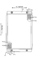
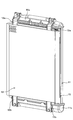
図1の車両用シャッタ単体を示す斜視図である。
図5の車両用シャッタの枠部材を示す斜視図である。
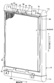
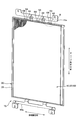
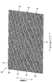
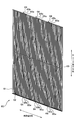
図5の車両用シャッタのシャッタ部材の斜視図である。
図5の車両用シャッタのシャッタ部材の斜視図である。
図5の車両用シャッタのシャッタ部材の斜視図である。
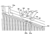
図5の車両用シャッタのB部分拡大図である。
図5の車両用シャッタのB部分拡大図である。
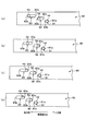
図4中のプッシュロッド単体のA矢視図である。
図4中のプッシュロッド単体のA矢視図である。
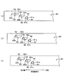
図4の遮風部材においてチューブ長手方向に直交する断面を示す図であって、シャッタ部材の遮風部材が空気通路を開けている状態を示す模式図である。
図4の遮風部材においてチューブ長手方向に直交する断面を示す図であって、シャッタ部材の遮風部材が空気通路を閉じている状態を示す模式図である。
一実施形態にかかる車両用シャッタが適用されているクーリングモジュール10を図1に基づいて説明する。
図1のクーリングモジュール10は、車両のフロントエンジンルーム20のうちフロントグリル開口部21と変速機構22との間に配置されている。フロントグリル開口部21は、フロントエンジンルーム20からその外側に車両進行方向前方にて開口する。変速機構22は、走行用エンジン23の回転出力を速度を変えて出力する。クーリングモジュール10は、ラジエータ11、コンデンサ12、電動ファン13、シュラウド14、および車両用シャッタ15を備える。
ラジエータ11は、図2に示すように、走行用エンジン23の冷却水を車室外空気により冷却する熱交換器である。ラジエータ11は、複数本のチューブ11a、タンク11b、11c、および複数のフィン11dとを備えている。ラジエータ11は、車両幅方向に平行に配置されている。
複数本のチューブ11aは、車両幅方向(所定方向)に並べられて積層されている。複数本のチューブ11aは、それぞれ、エンジン冷却水を流通させてエンジン冷却水と車室外空気との間で熱交換させる。タンク11bは、複数本のチューブ11aに対してチューブ長手方向一方側に配置されている。タンク11bは、走行用エンジン23の冷却水出口から排出されるエンジン冷却水を複数本のチューブ11aに対して分配する。
タンク11cは、タンク11bと、複数本のチューブ11aに対してチューブ長手方向他方側に配置されている。タンク11cは、複数本のチューブ11aを通過したエンジン冷却水を集合して走行用エンジン23の冷却水入口に導く。
複数本のチューブ11aのうち、隣り合う2本のチューブ11a間毎に、空気通路11eが形成されている。これにより、ラジエータ11には、複数の空気通路11eが形成されている。複数のフィン11dは、複数の空気通路11e内に配置されている。複数のフィン11dは、それぞれ、エンジン冷却水と車室外空気との間の熱交換を促進する。
コンデンサ12は、圧縮機、減圧弁、蒸発器とともに冷媒を循環させる空調装置用冷凍サイクル装置を構成するもので、圧縮機から吐出される高圧冷媒を車室外空気により冷却する熱交換器である。コンデンサ12は、ラジエータ11と同様に、複数本のチューブ、2つのタンク、および複数のフィンから形成されている。コンデンサ12は、フロントグリル開口部21とラジエータ11との間で車両幅方向に平行に配置されている。
電動ファン13は、フロントエンジンルーム20のうちラジエータ11に対して車両進行方向後側に配置されている。電動ファン13は、車両の前方からフロントグリル開口部21を通して吸い込んだ空気を、コンデンサ12、およびラジエータ11を通過させる空気流を発生させる。シュラウド14は、フロントグリル開口部21から吸い込んだ空気流をコンデンサ12およびラジエータ11を通過させるように整流させるケースである。
車両用シャッタ15は、コンデンサ12およびラジエータ11の間にて、コンデンサ12およびラジエータ11によって狭持されている開閉装置である。車両用シャッタ15は、図3および図4に示すように、そのブラケット16aがコンデンサ12のブラケット12aとともにラジエータ11のタンク11bに固定されている。車両用シャッタ15のブラケット16bは、コンデンサ12のブラケット12bとともに、ラジエータ11のタンク11cに固定されている。
車両用シャッタ15は、図4~図11に示すように、枠部材30、シャッタ部材40、50、60、アクチュエータ70、および、プッシュロッド80を備える。
枠部材30は、車両前後方向に向けて矩形状に開口している開口部31a(図6参照)を有する枠本体31と、枠本体31の上側に設けられているブラケット16aと、枠本体31の下側に設けられているブラケット16bとを備える。
シャッタ部材40は、枠部材30の開口部31a内に配置されている。シャッタ部材40は、図7に示すように、枠材41および複数本の遮風部材42を備える。
枠材41は、車両前後方向に向けて矩形状に開口している開口部を有する。複数本の遮風部材42は、それぞれ、チューブ11aの長手方向(以下、チューブ長手方向という)に平行に延びる長板状に形成されている。つまり、複数本の遮風部材42は、その長手方向がチューブ11aの長手方向に平行に配置されていることになる。遮風部材42の車両幅方向の寸法は、遮風部材42毎に、チューブ11aの車両幅方向の寸法以下になっている。
複数本の遮風部材42は、枠材41の開口部内において、車両幅方向にて、等間隔で並べられている。複数本の遮風部材42の長手方向一方側は、それぞれ、枠材41に支持されている。複数本の遮風部材42の長手方向他方側は、それぞれ、枠材41に支持されている。
複数本の遮風部材42のうち長手方向中央部は、梁部材43により支持されている。梁部材43は、車両幅方向に延びるように形成されている。梁部材43のうち長手方向一方側、および他方側は、枠材41に支持されている。
枠材41には、6つの支持ピン44が設けられている。6つの支持ピン44のうち3つの支持ピン44は、枠材41のうちチューブ長手方向一方側に設けられている。6つの支持ピン44のうち残りの3つの支持ピン44は、枠材41のうちチューブ長手方向他方側に設けられている。以下、6つの支持ピン44のうち枠材41のうちチューブ長手方向一方側に設けられている3つの支持ピン44を3つの上側支持ピン44という。6つの支持ピン44のうち枠材41のうちチューブ長手方向他方側に設けられている3つの支持ピン44を3つの下側支持ピン44という。
3つの上側支持ピン44は、それぞれ、枠材41のうちチューブ長手方向一方側からチューブ長手方向一方側に突起するように形成されている。3つの上側支持ピン44は、それぞれ間隔を開けて車両幅方向に並べられている。3つの上側支持ピン44は、それぞれ、支持ピン44毎に、シャッタ部材60の横溝65aを通して枠部材30の長溝32(図10、図11)を貫通している。長溝32は、上側支持ピン44毎に、車両幅方向に延びるように設けられている。
3つの下側支持ピン44は、それぞれ、枠材41のうちチューブ長手方向他方側からチューブ長手方向他方側に突起するように形成されている。3つの下側支持ピン44は、それぞれ、間隔を開けて車両幅方向に並べられている。3つの下側支持ピン44は、上側支持ピン44と同様に、下側支持ピン44b毎に、シャッタ部材60の横溝65aを通して枠部材30の長溝(図示省略)を貫通している。当該長溝は、下側支持ピン44毎に、枠部材30に設けられている。
ここで、長溝32の車両幅方向の寸法と下側長溝の車両幅方向の寸法とは同一である。以下、長溝32(或いは、下側長溝)の車両幅方向の寸法を寸法L1とする。
シャッタ部材50は、図8に示すように、枠材51、複数本の遮風部材52、梁部材53、および6つの支持ピン54を備え、シャッタ部材40と同様に形成されている。シャッタ部材50は、枠部材30の開口部31a内において、シャッタ部材40に対して車両前後方向後側に配置されている。
ここで、3つの上側支持ピン54は、上側支持ピン54毎に、シャッタ部材60の横溝65bを通して枠部材30の長溝33(図10、図11参照)を貫通している。長溝33は、上側支持ピン54毎に、枠部材30に設けられている。3つの下側支持ピン54は、下側支持ピン54毎に、シャッタ部材60の横溝65bを通して枠部材30の長溝を貫通している。長溝は、下側支持ピン54毎に、枠部材30に設けられている。
長溝33の車両幅方向寸法と下側支持ピン54が貫通する長溝の車両幅方向寸法とは同一である。以下、長溝33(或いは、長溝)の車両幅方向の寸法を寸法L2とする。
シャッタ部材60は、図9に示すように、枠材61、複数本の遮風部材62、梁部材63、および6つの支持ピン64を備え、シャッタ部材40と同様に形成されている。シャッタ部材60は、枠部材30の開口部31a内において、シャッタ部材50に対して車両前後方向後側に配置されている。
このように構成される実施形態では、シャッタ部材40、50、60は、ラジエータ11のうち空気流が入る空気流入面17a(図1参照)側に配置されている。遮風部材42、52、62は、空気通路11fを開閉するために、空気通路11e毎に3つずつ設けられていることになる。このため、遮風部材42、52、62は、空気通路11e毎に、スライド移動することにより、後述する空気通路11f(図14A、図14B参照)を開閉する。つまり、遮風部材42、52、62は、ラジエータ11の空気流入面17aに沿うようにスライド移動して、空気通路11fを開閉することになる。
ここで、3つの上側支持ピン64は、上側支持ピン64毎に、枠部材30の溝34を貫通している。長溝34は、上側支持ピン64毎に、枠部材30に設けられている。3つの下側支持ピン64は、下側支持ピン64毎に、枠部材30の長溝を貫通している。長溝は、下側支持ピン64毎に、枠部材30に設けられている。
長溝34の車両幅方向寸法と下側支持ピン64が貫通する長溝の車両幅方向寸法とは同一である。以下、長溝34(或いは、長溝)の車両幅方向の寸法を寸法L3とする。
このように6組の支持ピン44、54、64が組毎に長溝32、33、34内に配置されることにより、シャッタ部材40、50、60は、枠部材30によって、車両幅方向にスライド移動が可能に支持されることになる。
なお、上側支持ピン44、54、64を1組とすると、枠部材30のチューブ長手方向一方側において、上側支持ピン44、54、64が車両幅方向一方側、中間部、他方側に組毎に配置されることになる。下側支持ピン44、54、64を1組とすると、枠部材30のチューブ長手方向他方側において、下側支持ピン44、54、64が車両幅方向一方側、中間部、他方側に組毎に配置されることになる。このことにより、6組の支持ピン44、54、64が車両用シャッタ15に設けられることになる。
なお、枠材61、51は、枠材41に対応し、遮風部材62、52は、遮風部材42に対応している。梁部材63、53は、梁部材43に対応し、支持ピン64、54は、支持ピン44に対応している。
本実施形態では、L1>L2>L3が成立するように長溝32、33、34の車両幅方向の寸法が設定されている。このため、シャッタ部材40の移動可能距離D1とし、シャッタ部材50の移動可能距離D2とし、シャッタ部材60の移動可能距離D3とすると、D1>D2>D3となる。
さらに、アクチュエータ70(図4参照)は、プッシュロッド80を車両幅方向一方側、或いは他方側にスライド移動させる。アクチュエータ70は、タンク11bに固定されている。
本実施形態のアクチュエータ70としては、プッシュロッド80を直線方向に駆動させる駆動源(例えば、電磁石、形状記憶合金、サーモワックス、リニアモータなど)を用いることができる。
プッシュロッド80は、L字状に形成されている角柱部材である。プッシュロッド80は、アクチュエータ70により駆動されて車両幅方向一方側、或いは他方側にスライド移動する。プッシュロッド80のうち車両幅方向一方側には、チューブ長手方向に貫通する貫通孔81、82、83(図12(a)~(d)、図13(a)~(c)参照)が設けられている。なお、図12(a)~(d)、図13(a)~(c)は、図4中のプッシュロッド80のA矢視図である。なお、図4では、貫通孔81、82、83および支持ピン44、54、64の図示を省略している。
貫通孔81には、支持ピン44が入っている。貫通孔82には、支持ピン54が入っている。貫通孔83には、支持ピン64が入っている。貫通孔82、83は、車両幅方向に延びるように形成されている。貫通孔81のうち車両幅方向の寸法をH1とし、貫通孔82のうち車両幅方向の寸法をH2とし、貫通孔83のうち車両幅方向の寸法をH3とすると、H1<H2<H3となるように貫通孔81、82、83が設定されている。
このように貫通孔81、82、83が設定されることにより、支持ピン44は、プッシュロッド80とともにスライド移動する。支持ピン54が支持ピン44に対して遅れてスライド移動し、かつ支持ピン64が支持ピン54に対して遅れてスライド移動する。このことにより、プッシュロッド80のスライド移動により、シャッタ部材40、50、60がそれぞれ異なる距離をスライド移動することができる。
次に、本実施形態の作動について説明する。
まず、コンデンサ12およびラジエータ11には、空気通路11e毎に、空気通路11eを通過する空気流が流れる空気通路11fが形成されている(図14A参照)。
ここで、空気通路11fを流れる複数の空気流のうち最も風量の多い主流の空気流れ方向は、車両進行方向に一致する。主流は、電動ファン13の駆動により車両前方からフロントグリル開口部21を通して導入されてコンデンサ12およびラジエータ11を通過する空気流、或いは車両の走行に伴って車両前方からフロントグリル開口部21を通して導入されてコンデンサ12およびラジエータ11を通過する走行風としての空気流である。このため、シャッタ部材40、50、60がスライド移動する方向は、主流の空気流れ方向に対して直交することになる。
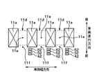
例えば、図10に示すように、6組の支持ピン44、54、64が、枠部材30のうちそれぞれ対応する長溝32、33、34の車両幅方向一方側(図10中右端)に位置する。このとき、図14Aに示すように、シャッタ部材40の複数の遮風部材42、シャッタ部材50の複数の遮風部材52、およびシャッタ部材60の複数の遮風部材62がそれぞれ対応するチューブ11aに対して空気流れ下流側に位置する。
ここで、対応するチューブ11a空気流れ下流側には、空気通路11f毎に、遮風部材42、52、62が車両前後方向(空気流れ方向)に並べられている。すなわち、遮風部材42、52、62が空気通路11f毎に空気通路11fに対して車両幅方向一方側に位置する。遮風部材42、52、62は、空気通路11f毎に、車両前後方向から視て重なるように配置されている。このことにより、遮風部材42、52、62は、空気通路11f毎に、空気通路11fを開けている。このため、車両前方からフロントグリル開口部21を通して導入される空気流は、コンデンサ12、ラジエータ11、および電動ファン13を通して変速機構22側に流れる。
このとき、図12(a)に示すように、支持ピン54は貫通孔82のうち車両幅方向他方側に位置する。支持ピン64は貫通孔83のうち車両幅方向他方側に位置する。
次に、コンデンサとラジエータを冷却しない時は、アクチュエータ70がプッシュロッド80を車両幅方向他方側に移動させる。
これに伴い、プッシュロッド80において貫通孔81を形成する形成部のうち車両幅方向一方側端部(以下、貫通孔一方側端部81aという)が上側支持ピン44を車両幅方向他方側に押す。このため、6つの支持ピン44がそれぞれ対応する長溝32内を車両幅方向他方側に移動する。このため、シャッタ部材40が車両幅方向他方側に移動する。
その後、プッシュロッド80において貫通孔82を形成する形成部のうち車両幅方向一方側端部(以下、貫通孔一方側端部82aという)が上側支持ピン54に接触する。このため、貫通孔一方側端部82aが上側支持ピン54を車両幅方向他方側に押し始める(図12(b)参照)。このため、プッシュロッド80が上側支持ピン54を車両幅方向他方側に移動させることを開始する。これに伴い、6つの支持ピン54がそれぞれ対応する長溝33内を車両幅方向他方側に移動する。このため、シャッタ部材50がシャッタ部材40とともに車両幅方向他方側に移動する。
その後、プッシュロッド80において貫通孔83を形成する形成部のうち車両幅方向一方側端部(以下、貫通孔一方側端部83aという)が上側支持ピン64に接触する(図12(c)参照)。このため、貫通孔一方側端部83aが上側支持ピン64を車両幅方向他方側に押し始める。このため、プッシュロッド80が上側支持ピン64を車両幅方向他方側に移動させることを開始する。その後、上側支持ピン44、54、64が貫通孔一方側端部81a、82a、83aに押されて車両幅方向他方側に移動する(図12(d)参照)。これに伴い、6つの支持ピン64がそれぞれ対応する長溝34内を車両幅方向他方側に移動する。このため、シャッタ部材40、50、60が車両幅方向他方側に移動する。その後、6組の支持ピン44、54、64が、枠部材30のうちそれぞれ対応する長溝32、33、34の車両幅方向他方側(図11中左端)に位置する。そして、アクチュエータ70がプッシュロッド80を停止する。
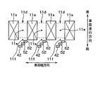
このとき、図14Bに示すように、空気通路11e毎に遮風部材42、52、62が、それぞれ対応する空気通路11eに対して空気流れ下流側に位置する。このとき、遮風部材42、52、62が空気通路11e毎に車両幅方向にオフセットして位置する。このことにより、遮風部材42、52、62が空気通路11f毎に空気通路11fを隣り合う2本のチューブ11aの間に亘って閉塞することになる。
次に、コンデンサとラジエータを冷却したい時は、アクチュエータ70がプッシュロッド80を車両幅方向一方側に移動させる。
これに伴い、プッシュロッド80において貫通孔81を形成する形成部のうち車両幅方向他方側端部(以下、貫通孔他方側端部81bという)が上側支持ピン44を車両幅方向一方側に押す。このため、6つの支持ピン44がそれぞれ対応する長溝32内を車両幅方向一方側に移動する。このため、シャッタ部材40が車両幅方向一方側に移動する。
その後、プッシュロッド80において貫通孔82を形成する形成部のうち車両幅方向他方側端部(以下、貫通孔他方側端部82bという)が上側支持ピン54に接触する(図13(a)参照)。このため、貫通孔他方側端部82bが上側支持ピン54を車両幅方向一方側に押し始める。このため、プッシュロッド80が上側支持ピン54を車両幅方向一方側に移動させることを開始する。これに伴い、6つの支持ピン54がそれぞれ対応する長溝33内を車両幅方向一方側に移動する。このため、シャッタ部材50がシャッタ部材40とともに車両幅方向一方側に移動する。
その後、プッシュロッド80において貫通孔83を形成する形成部のうち車両幅方向他方側端部(以下、貫通孔他方側端部83bという)が上側支持ピン64に接触する(図13(b)参照)。このため、貫通孔他方側端部83bが上側支持ピン64を車両幅方向一方側に押し始める。このため、プッシュロッド80が上側支持ピン64を車両幅方向一方側に移動させることを開始する。その後、上側支持ピン44、54、64が貫通孔他方側端部81b、82b、83bに押されて車両幅方向一方側に移動する(図13(c)参照)。これに伴い、6つの支持ピン64がそれぞれ対応する長溝32、33、34内を車両幅方向一方側に移動する。このため、シャッタ部材40、50、60が車両幅方向一方側に移動する。その後、6組の支持ピン44、54、64が、枠部材30のうちそれぞれ対応する長溝32、33、34の車両幅方向一方側(図10中右端)に位置する。そして、アクチュエータ70がプッシュロッド80を停止する。このとき、図14Aに示すように、空気通路11f毎の遮風部材42、52、62がそれぞれ対応するチューブ11aに対して空気流れ下流側に位置する。このことにより、遮風部材42、52、62が、空気通路11f毎に空気通路11fを開けることになる。
以上説明した本実施形態によれば、車両用シャッタ15は、ラジエータ11を通過する空気を流通させる空気通路11f内の空気流れ方向に対して直交する車両幅方向にスライド移動が可能に支持される遮風部材42、52、62と、遮風部材42、52、62を押して車両幅方向に遮風部材42、52、62をプッシュロッド80を介して移動させるアクチュエータ70を備える。そして、遮風部材42、52、62が空気通路11f毎に車両幅方向一方側に位置するとき、遮風部材42、52、62が空気通路11f毎に空気通路11fを開ける。遮風部材42、52、62が空気通路11f毎に車両幅方向他方側に位置するとき、遮風部材42、52、62が空気通路11f毎に空気通路11fを閉じる。言い換えれば、遮風部材42、52、62は、空気通路11f内の空気流れ方向に対して交差する交差方向の他方側に位置するとき、一方側に位置する場合よりも空気通路11fの開度を減少する。
以上により、遮風部材42、52、62を車両幅方向にスライド移動することにより、空気通路11fを開閉することができる。このため、車両用シャッタ15において、空気流れ方向、すなわち車両前後方向の寸法を、上記特許文献1に記載の車両用シャッタより小さくすることができる。このため、車両用シャッタ15の車両搭載性を向上することができる。
さらに、本実施形態の車両用シャッタ15は、上記特許文献1に記載の車両用シャッタに比べて部品点数を少なくすることができる。このため、製造時の組み付け工数を減らすことができるので、コストを低減することができる。
本実施形態のアクチュエータ70としては、シャッタ部材40、50、60を直線方向(車両幅方向)に駆動させる駆動源を用いている。ここで、シャッタ部材40、50、60を回転させる場合には、風圧に打ち勝つ回転力をシャッタ部材40、50、60に与えるアクチュエータ70を用いることが必要となる。このため、アクチュエータ70のコストの増大化を招いていた。
これに対して、本実施形態では、アクチュエータ70としては、上述の如く、シャッタ部材40、50、60を直線方向に駆動させる駆動源を用いることができる。このため、アクチュエータ70からシャッタ部材40、50、60に与える移動力を下げることができる。このため、シャッタ部材40、50、60を回転させる場合に比べて、低コストのアクチュエータ70を用いることができる。
本実施形態では、複数組の遮風部材42、52、62が組毎に対応する空気通路11fを開ける際に、複数組の遮風部材42、52、62は、組毎に、複数本のチューブ11aのうち対応するチューブ11aに対して空気流れ方向上流側に位置する。これに加えて、複数組の遮風部材42、52、62は、組毎に、空気流れ方向(車両進行方向)に並べられている。遮風部材42、52、62のそれぞれの車両幅方向寸法は、チューブ11aの車両幅方向寸法以下になっている。このため、複数組の遮風部材42、52、62が空気通路11eを流れる空気流を阻害することを防ぐことができる。
仮に、遮風部材が空気流れ方向下流側に位置する場合、空気流れによって遮風部材がたわみやすくなるが、本実施形態においては、遮風部材42、52、62が空気流れ方向上流側に位置することにより、遮風部材42、52、62がたわみにくくなる。このため、遮風部材42、52、62の厚みが比較的薄い場合であっても、遮風部材42、52、62の強度を補強する必要がない。
本実施形態では、車両用シャッタ15は、ラジエータ11およびコンデンサ12の間に配置されている。このため、ラジエータ11およびコンデンサ12の間のデットスペースを有効利用して車両用シャッタ15を配置することができる。
本実施形態では、遮風部材42、52、62が空気通路11e毎に隣り合う2本のチューブ11aの間に亘って空気通路11eを閉鎖する。言い換えれば、ラジエータ11は交差方向に並べられた複数のチューブ11aを有して構成されており、遮風部材42、52、62が交差方向の他方側に位置するとき、遮風部材42、52、62が交差方向において隣り合う2本のチューブの間に亘って空気通路11eを閉じる。したがって、空気通路11eを空気が流れることを確実に防ぐことができる。これにより、ラジエータ11において、エンジン冷却水と車室外空気との間の熱交換を阻害することができる。このため、走行用エンジンの暖機を促進することができる。
(他の実施形態)
上記実施形態において、遮風部材として、3つの遮風部材42、52、62を用いた例について説明したが、これに代えて、1つの遮風部材、2つの遮風部材、或いは、4つ以上の遮風部材を用いてもよい。
上記実施形態において、遮風部材として、3つの遮風部材42、52、62を用いた例について説明したが、これに代えて、1つの遮風部材、2つの遮風部材、或いは、4つ以上の遮風部材を用いてもよい。
上記実施形態において、ラジエータ11およびコンデンサ12の間に車両用シャッタ15を配置した例について説明したが、これに代えて、ラジエータ11に対して空気流れ下流側に車両用シャッタ15を配置してもよく、或いは、コンデンサ12に対して空気流れ上流側に車両用シャッタ15を配置してもよい。
特に、コンデンサ12に対して空気流れ上流側に車両用シャッタ15を配置する場合には、車両用シャッタ15が路上の石等がコンデンサ12に当たることを防ぐストーンガードとしての機能を果たすことができる。
さらに、コンデンサ12に対して空気流れ上流側に車両用シャッタ15を配置する場合には、遮風部材42、52、62を黒色に塗装して、車両停止時に、遮風部材42、52、62により空気通路11eを閉じるようにアクチュエータ70を制御すれば、コンデンサ12を黒色に塗装することなく、コンデンサ12の目隠しをすることができる。
上記実施形態において、1本のプッシュロッド80でシャッタ部材40、50、60をスライド移動させた例について説明したが、これに代えて、3本のプッシュロッド80でシャッタ部材40、50、60をスライド移動させてもよい。
上記実施形態において、シャッタ部材40、50、60およびアクチュエータ70の間のリンク機構として、プッシュロッド80を用いた例について説明したが、これに限らず、プッシュロッド80を用いないリンク機構を用いてもよい。
上記実施形態において、熱交換器をラジエータ11とした例について説明したが、これに代えて、熱交換器をラジエータ11以外の熱交換器(例えば、エンジンオイルを冷却するオイルクーラ)としてもよい。この場合、車両用シャッタ15としては、フロントグリル開口部21のうちコンデンサ12およびラジエータ11からオフセットした位置に配置してもよい。車両用シャッタ15としては、熱交換器に向かって流れる空気流が流通する空気通路11f内の空気流れ方向に交差する交差方向にシャッタ部材40、50、60がスライド移動可能に支持されることになる。或いは、上記実施形態において、熱交換器をコンデンサ12としてもよい。
上記実施形態において、冷却水の水流れ方向が車両上下方向であるラジエータにおいてシャッタ部材40、50、60をスライド移動させる方向を、空気通路11f内の空気流れ方向に対して直交する車両幅方向とした例について説明したが、冷却水の水流れ方向が車両左右方向であるラジエータにおいては、シャッタ部材40、50、60をスライド移動させる方向を車両上下方向としてもよい。
上記実施形態において、複数本のチューブ11aを空気通路11f内の空気流れ方向に対して直交する車両幅方向に並べた例について説明したが、これに限らず、複数本のチューブ11aを並べる方向としては、空気通路11f内の空気流れ方向に対して交差する方向あれば、空気通路11f内の空気流れ方向に対して直交する方向以外の方向であってもよい。
上記実施形態において、遮風部材42、52、62をラジエータ11の空気流入面17aに沿うようにスライド移動が可能に構成した例について説明したが、これに代えて、遮風部材42、52、62をラジエータ11のうち空気流が出る空気流出面17bに沿うようにスライド移動が可能に構成してもよい。
車両用シャッタを適用する車両としては、軽自動車や小型車両に限定されなく、中型車以上の各種の車両に適用してもよい。
上記実施形態において、車両用シャッタを自動車に適用した例について説明したが、これに代えて、車両用シャッタを自動車以外の列車等に適用してもよい。
なお、本開示は上記した実施形態に限定されるものではなく、特許請求の範囲に記載した範囲内において適宜変更が可能である。また、上記各実施形態は、互いに無関係なものではなく、組み合わせが明らかに不可な場合を除き、適宜組み合わせが可能である。また、上記各実施形態において、実施形態を構成する要素は、特に必須であると明示した場合および原理的に明らかに必須であると考えられる場合等を除き、必ずしも必須のものではないことは言うまでもない。また、上記各実施形態において、実施形態の構成要素の個数、数値、量、範囲等の数値が言及されている場合、特に必須であると明示した場合および原理的に明らかに特定の数に限定される場合等を除き、その特定の数に限定されるものではない。また、上記各実施形態において、構成要素等の形状、位置関係等に言及するときは、特に明示した場合および原理的に特定の形状、位置関係等に限定される場合等を除き、その形状、位置関係等に限定されるものではない。
Claims (14)
- 熱交換器(11)を通過する空気流が流通する空気通路(11f)を開閉する車両用シャッタであって、
前記空気通路内の空気流れ方向に対して交差する交差方向にスライド移動が可能な遮風部材(42、52、62)を備え、
前記遮風部材は、前記交差方向の一方側に位置するとき前記空気通路を開け、
前記遮風部材は、前記交差方向の他方側に位置するとき前記空気通路を閉じる車両用シャッタ。 - 前記遮風部材は、前記熱交換器のうち前記空気流が入る空気流入面(17a)、および前記空気流が出る空気流出面(17b)のうち一方の面に沿うようにスライド移動が可能に構成されている請求項1に記載の車両用シャッタ。
- 前記遮風部材は、前記空気流れ方向に対して直交する方向にスライド移動が可能に構成されている請求項1または2に記載の車両用シャッタ。
- 前記遮風部材を前記交差方向の一方側、或いは前記交差方向の他方側に移動させる駆動部(70、80)を備える請求項1ないし3のいずれか1つに記載の車両用シャッタ。
- 前記熱交換器は、前記交差方向に並べられた複数のチューブ(11a)を有して構成されており、
前記空気通路内の空気流が前記複数のチューブの間を通過するように前記空気通路が形成されており、
前記遮風部材が前記交差方向の一方側に位置するとき、前記遮風部材が前記複数のチューブのうち対応するチューブに対して前記空気流れ方向に配置されることにより、前記遮風部材が前記空気通路を開ける請求項1ないし4のいずれか1つに記載の車両用シャッタ。 - 前記遮風部材は、前記複数のチューブの間のそれぞれに対応して設けられる複数の遮風部材の一つであり、
前記複数の遮風部材は前記交差方向の他方側に位置するとき、前記複数の遮風部材が互いに前記交差方向にオフセットして配置されることにより、前記複数の遮風部材が前記空気通路を閉じる請求項5に記載の車両用シャッタ。 - 前記複数の遮風部材が前記交差方向の一方側に位置するとき、前記複数の遮風部材が前記対応するチューブに対して前記空気流れ方向に並ぶように配置されることにより、前記複数の遮風部材が前記空気通路を開ける請求項6に記載の車両用シャッタ。
- 前記複数の遮風部材のそれぞれの前記交差方向の寸法は、前記対応するチューブにおける前記交差方向の寸法以下になっている請求項7に記載の車両用シャッタ。
- 前記熱交換器は、前記交差方向に並べられた複数のチューブ(11a)を有して構成されており、
前記遮風部材が前記交差方向の他方側に位置するとき、前記遮風部材が前記複数のチューブのうち隣り合う2本のチューブの間に亘って前記空気通路を閉じる請求項1ないし8のいずれか1つに記載の車両用シャッタ。 - 前記遮風部材は、前記熱交換器に対して前記空気流れ方向の上流側に配置されている請求項1ないし9のいずれか1つに記載の車両用シャッタ。
- 請求項1ないし10のいずれか1つに記載の車両用シャッタ(15)と、
走行用エンジンの冷却水を車室外空気により冷却するラジエータとしての前記熱交換器(11)と、
を備える熱交換器モジュール。 - 熱交換器(11)を通過する空気流が流通する空気通路(11f)を開閉する車両用シャッタであって、
前記空気通路内の空気流れ方向に対して交差する交差方向にスライド移動が可能な遮風部材(42、52、62)を備え、
前記遮風部材は、前記交差方向の一方側に位置するとき前記空気通路を開け、
前記遮風部材は、前記交差方向の他方側に位置するとき、一方側に位置する場合よりも前記空気通路の開度を減少する車両用シャッタ。 - 前記熱交換器は、前記交差方向に並べられた複数のチューブ(11a)を有して構成されており、
前記遮風部材が前記交差方向の他方側に位置するとき、前記遮風部材が前記交差方向において前記複数のチューブのうち隣り合う2本のチューブの間に亘って前記空気通路を閉じる請求項12に記載の車両用シャッタ。 - 前記遮風部材が、走行用エンジンの冷却水を車室外空気により冷却するラジエータとしての前記熱交換器(11)とコンデンサ(12)の間に設けられている請求項12または13に記載の車両用シャッタ。
Priority Applications (2)
| Application Number | Priority Date | Filing Date | Title |
|---|---|---|---|
| CN201580048510.9A CN106687322A (zh) | 2014-11-27 | 2015-11-17 | 车辆用开闭体、以及热交换器组件 |
| DE112015005327.1T DE112015005327T5 (de) | 2014-11-27 | 2015-11-17 | Kühlerjalousie für Fahrzeug und Wärmetauschermodul |
Applications Claiming Priority (2)
| Application Number | Priority Date | Filing Date | Title |
|---|---|---|---|
| JP2014-240153 | 2014-11-27 | ||
| JP2014240153A JP2016101787A (ja) | 2014-11-27 | 2014-11-27 | 車両用シャッタ、および車載熱交換器モジュール |
Publications (1)
| Publication Number | Publication Date |
|---|---|
| WO2016084340A1 true WO2016084340A1 (ja) | 2016-06-02 |
Family
ID=56073934
Family Applications (1)
| Application Number | Title | Priority Date | Filing Date |
|---|---|---|---|
| PCT/JP2015/005735 Ceased WO2016084340A1 (ja) | 2014-11-27 | 2015-11-17 | 車両用シャッタ、および熱交換器モジュール |
Country Status (4)
| Country | Link |
|---|---|
| JP (1) | JP2016101787A (ja) |
| CN (1) | CN106687322A (ja) |
| DE (1) | DE112015005327T5 (ja) |
| WO (1) | WO2016084340A1 (ja) |
Families Citing this family (2)
| Publication number | Priority date | Publication date | Assignee | Title |
|---|---|---|---|---|
| JP7331335B2 (ja) * | 2018-07-24 | 2023-08-23 | 株式会社デンソー | 組立体 |
| EP4385781A1 (en) * | 2022-12-12 | 2024-06-19 | Volvo Truck Corporation | An electronic control unit, a system, and a method for protecting a radiator, and a vehicle provided with the same |
Citations (4)
| Publication number | Priority date | Publication date | Assignee | Title |
|---|---|---|---|---|
| JP2002192962A (ja) * | 2000-10-20 | 2002-07-10 | Modine Mfg Co | 車両冷却システム |
| JP2009541120A (ja) * | 2006-06-30 | 2009-11-26 | スカニア シーブイ アクチボラグ(パブル) | 自動車用の冷却装置 |
| JP2009541119A (ja) * | 2006-06-30 | 2009-11-26 | スカニア シーブイ アクチボラグ(パブル) | 自動車用の冷却装置 |
| JP2013505873A (ja) * | 2009-09-29 | 2013-02-21 | ヴァレオ システム テルミク | 自動車用の熱交換ブロック |
Family Cites Families (4)
| Publication number | Priority date | Publication date | Assignee | Title |
|---|---|---|---|---|
| US1492897A (en) * | 1921-11-16 | 1924-05-06 | Ryder Elmer | Radiator shutter |
| DE102006053883A1 (de) * | 2006-11-14 | 2008-05-15 | Friedrich Graepel Ag | Kühlerbaugruppe für ein Fahrzeug |
| JP4905314B2 (ja) * | 2006-12-28 | 2012-03-28 | 日産自動車株式会社 | 格子部材及び該格子部材を有する車両前部構造 |
| KR100969077B1 (ko) * | 2007-10-09 | 2010-07-09 | 현대자동차주식회사 | 유입 공간 내 자연 대류 흐름을 형성하는 외기 도입 그릴 |
-
2014
- 2014-11-27 JP JP2014240153A patent/JP2016101787A/ja active Pending
-
2015
- 2015-11-17 DE DE112015005327.1T patent/DE112015005327T5/de not_active Withdrawn
- 2015-11-17 WO PCT/JP2015/005735 patent/WO2016084340A1/ja not_active Ceased
- 2015-11-17 CN CN201580048510.9A patent/CN106687322A/zh active Pending
Patent Citations (4)
| Publication number | Priority date | Publication date | Assignee | Title |
|---|---|---|---|---|
| JP2002192962A (ja) * | 2000-10-20 | 2002-07-10 | Modine Mfg Co | 車両冷却システム |
| JP2009541120A (ja) * | 2006-06-30 | 2009-11-26 | スカニア シーブイ アクチボラグ(パブル) | 自動車用の冷却装置 |
| JP2009541119A (ja) * | 2006-06-30 | 2009-11-26 | スカニア シーブイ アクチボラグ(パブル) | 自動車用の冷却装置 |
| JP2013505873A (ja) * | 2009-09-29 | 2013-02-21 | ヴァレオ システム テルミク | 自動車用の熱交換ブロック |
Also Published As
| Publication number | Publication date |
|---|---|
| DE112015005327T5 (de) | 2017-08-17 |
| JP2016101787A (ja) | 2016-06-02 |
| CN106687322A (zh) | 2017-05-17 |
Similar Documents
| Publication | Publication Date | Title |
|---|---|---|
| US8919470B2 (en) | Grille shutter device | |
| WO2016079938A1 (ja) | エンジンルーム通風構造 | |
| US11718149B2 (en) | Vehicular air conditioning unit | |
| KR101680825B1 (ko) | 자동차용 프론트 엔드 모듈 | |
| KR101693348B1 (ko) | 액티브 에어 플랩 | |
| KR101936726B1 (ko) | 액티브 에어 플랩 | |
| WO2016084340A1 (ja) | 車両用シャッタ、および熱交換器モジュール | |
| WO2015059890A1 (ja) | 冷却システム | |
| KR101714381B1 (ko) | 액티브 에어 플랩 | |
| JP6265303B2 (ja) | 車両用空調ユニット | |
| JP5890720B2 (ja) | 可変ダクト支持構造 | |
| JP2016088118A (ja) | 車両 | |
| KR20110107706A (ko) | 액티브 에어 플랩 | |
| KR102789099B1 (ko) | 차량용 액티브 에어 플랩 장치 | |
| JP4600187B2 (ja) | 空調装置 | |
| JP2018192882A (ja) | 車両用熱交換器のシャッター構造 | |
| KR20150070770A (ko) | 액티브 에어 플랩 | |
| KR20150124725A (ko) | 차량용 에어 가이드 유닛 | |
| GB2580365A (en) | Motor vehicle assemblies | |
| JP6286190B2 (ja) | 空調装置用ダンパ | |
| WO2019069702A1 (ja) | 車両用空調ユニット | |
| KR20200087456A (ko) | 액티브 에어 플랩 | |
| JP4735360B2 (ja) | 車両用冷却装置 | |
| JP6306305B2 (ja) | 車両用空調装置 | |
| JP6504860B2 (ja) | 車両用空調装置 |
Legal Events
| Date | Code | Title | Description |
|---|---|---|---|
| 121 | Ep: the epo has been informed by wipo that ep was designated in this application |
Ref document number: 15862182 Country of ref document: EP Kind code of ref document: A1 |
|
| WWE | Wipo information: entry into national phase |
Ref document number: 112015005327 Country of ref document: DE |
|
| 122 | Ep: pct application non-entry in european phase |
Ref document number: 15862182 Country of ref document: EP Kind code of ref document: A1 |