WO2016084271A1 - 射出成形方法、及び、射出成形機 - Google Patents
射出成形方法、及び、射出成形機 Download PDFInfo
- Publication number
- WO2016084271A1 WO2016084271A1 PCT/JP2015/003202 JP2015003202W WO2016084271A1 WO 2016084271 A1 WO2016084271 A1 WO 2016084271A1 JP 2015003202 W JP2015003202 W JP 2015003202W WO 2016084271 A1 WO2016084271 A1 WO 2016084271A1
- Authority
- WO
- WIPO (PCT)
- Prior art keywords
- screw
- reverse
- rotation
- molten resin
- injection molding
- Prior art date
- Legal status (The legal status is an assumption and is not a legal conclusion. Google has not performed a legal analysis and makes no representation as to the accuracy of the status listed.)
- Ceased
Links
Images







Classifications
-
- B—PERFORMING OPERATIONS; TRANSPORTING
- B29—WORKING OF PLASTICS; WORKING OF SUBSTANCES IN A PLASTIC STATE IN GENERAL
- B29C—SHAPING OR JOINING OF PLASTICS; SHAPING OF MATERIAL IN A PLASTIC STATE, NOT OTHERWISE PROVIDED FOR; AFTER-TREATMENT OF THE SHAPED PRODUCTS, e.g. REPAIRING
- B29C45/00—Injection moulding, i.e. forcing the required volume of moulding material through a nozzle into a closed mould; Apparatus therefor
- B29C45/0005—Injection moulding, i.e. forcing the required volume of moulding material through a nozzle into a closed mould; Apparatus therefor using fibre reinforcements
-
- B—PERFORMING OPERATIONS; TRANSPORTING
- B29—WORKING OF PLASTICS; WORKING OF SUBSTANCES IN A PLASTIC STATE IN GENERAL
- B29B—PREPARATION OR PRETREATMENT OF THE MATERIAL TO BE SHAPED; MAKING GRANULES OR PREFORMS; RECOVERY OF PLASTICS OR OTHER CONSTITUENTS OF WASTE MATERIAL CONTAINING PLASTICS
- B29B7/00—Mixing; Kneading
- B29B7/30—Mixing; Kneading continuous, with mechanical mixing or kneading devices
- B29B7/34—Mixing; Kneading continuous, with mechanical mixing or kneading devices with movable mixing or kneading devices
- B29B7/38—Mixing; Kneading continuous, with mechanical mixing or kneading devices with movable mixing or kneading devices rotary
- B29B7/46—Mixing; Kneading continuous, with mechanical mixing or kneading devices with movable mixing or kneading devices rotary with more than one shaft
- B29B7/48—Mixing; Kneading continuous, with mechanical mixing or kneading devices with movable mixing or kneading devices rotary with more than one shaft with intermeshing devices, e.g. screws
- B29B7/484—Mixing; Kneading continuous, with mechanical mixing or kneading devices with movable mixing or kneading devices rotary with more than one shaft with intermeshing devices, e.g. screws with two shafts provided with screws, e.g. one screw being shorter than the other
-
- B—PERFORMING OPERATIONS; TRANSPORTING
- B29—WORKING OF PLASTICS; WORKING OF SUBSTANCES IN A PLASTIC STATE IN GENERAL
- B29B—PREPARATION OR PRETREATMENT OF THE MATERIAL TO BE SHAPED; MAKING GRANULES OR PREFORMS; RECOVERY OF PLASTICS OR OTHER CONSTITUENTS OF WASTE MATERIAL CONTAINING PLASTICS
- B29B7/00—Mixing; Kneading
- B29B7/30—Mixing; Kneading continuous, with mechanical mixing or kneading devices
- B29B7/58—Component parts, details or accessories; Auxiliary operations
- B29B7/60—Component parts, details or accessories; Auxiliary operations for feeding, e.g. end guides for the incoming material
-
- B—PERFORMING OPERATIONS; TRANSPORTING
- B29—WORKING OF PLASTICS; WORKING OF SUBSTANCES IN A PLASTIC STATE IN GENERAL
- B29B—PREPARATION OR PRETREATMENT OF THE MATERIAL TO BE SHAPED; MAKING GRANULES OR PREFORMS; RECOVERY OF PLASTICS OR OTHER CONSTITUENTS OF WASTE MATERIAL CONTAINING PLASTICS
- B29B7/00—Mixing; Kneading
- B29B7/80—Component parts, details or accessories; Auxiliary operations
- B29B7/88—Adding charges, i.e. additives
- B29B7/90—Fillers or reinforcements, e.g. fibres
-
- B—PERFORMING OPERATIONS; TRANSPORTING
- B29—WORKING OF PLASTICS; WORKING OF SUBSTANCES IN A PLASTIC STATE IN GENERAL
- B29C—SHAPING OR JOINING OF PLASTICS; SHAPING OF MATERIAL IN A PLASTIC STATE, NOT OTHERWISE PROVIDED FOR; AFTER-TREATMENT OF THE SHAPED PRODUCTS, e.g. REPAIRING
- B29C45/00—Injection moulding, i.e. forcing the required volume of moulding material through a nozzle into a closed mould; Apparatus therefor
- B29C45/17—Component parts, details or accessories; Auxiliary operations
- B29C45/46—Means for plasticising or homogenising the moulding material or forcing it into the mould
- B29C45/47—Means for plasticising or homogenising the moulding material or forcing it into the mould using screws
- B29C45/50—Axially movable screw
-
- B—PERFORMING OPERATIONS; TRANSPORTING
- B29—WORKING OF PLASTICS; WORKING OF SUBSTANCES IN A PLASTIC STATE IN GENERAL
- B29C—SHAPING OR JOINING OF PLASTICS; SHAPING OF MATERIAL IN A PLASTIC STATE, NOT OTHERWISE PROVIDED FOR; AFTER-TREATMENT OF THE SHAPED PRODUCTS, e.g. REPAIRING
- B29C45/00—Injection moulding, i.e. forcing the required volume of moulding material through a nozzle into a closed mould; Apparatus therefor
- B29C45/17—Component parts, details or accessories; Auxiliary operations
- B29C45/76—Measuring, controlling or regulating
-
- B—PERFORMING OPERATIONS; TRANSPORTING
- B29—WORKING OF PLASTICS; WORKING OF SUBSTANCES IN A PLASTIC STATE IN GENERAL
- B29B—PREPARATION OR PRETREATMENT OF THE MATERIAL TO BE SHAPED; MAKING GRANULES OR PREFORMS; RECOVERY OF PLASTICS OR OTHER CONSTITUENTS OF WASTE MATERIAL CONTAINING PLASTICS
- B29B7/00—Mixing; Kneading
- B29B7/80—Component parts, details or accessories; Auxiliary operations
- B29B7/88—Adding charges, i.e. additives
- B29B7/90—Fillers or reinforcements, e.g. fibres
- B29B7/905—Fillers or reinforcements, e.g. fibres with means for pretreatment of the charges or fibres
-
- B—PERFORMING OPERATIONS; TRANSPORTING
- B29—WORKING OF PLASTICS; WORKING OF SUBSTANCES IN A PLASTIC STATE IN GENERAL
- B29C—SHAPING OR JOINING OF PLASTICS; SHAPING OF MATERIAL IN A PLASTIC STATE, NOT OTHERWISE PROVIDED FOR; AFTER-TREATMENT OF THE SHAPED PRODUCTS, e.g. REPAIRING
- B29C2945/00—Indexing scheme relating to injection moulding, i.e. forcing the required volume of moulding material through a nozzle into a closed mould
- B29C2945/76—Measuring, controlling or regulating
- B29C2945/76494—Controlled parameter
- B29C2945/76595—Velocity
- B29C2945/76605—Velocity rotational movement
-
- B—PERFORMING OPERATIONS; TRANSPORTING
- B29—WORKING OF PLASTICS; WORKING OF SUBSTANCES IN A PLASTIC STATE IN GENERAL
- B29C—SHAPING OR JOINING OF PLASTICS; SHAPING OF MATERIAL IN A PLASTIC STATE, NOT OTHERWISE PROVIDED FOR; AFTER-TREATMENT OF THE SHAPED PRODUCTS, e.g. REPAIRING
- B29C2945/00—Indexing scheme relating to injection moulding, i.e. forcing the required volume of moulding material through a nozzle into a closed mould
- B29C2945/76—Measuring, controlling or regulating
- B29C2945/76655—Location of control
- B29C2945/76658—Injection unit
- B29C2945/76665—Injection unit screw
-
- B—PERFORMING OPERATIONS; TRANSPORTING
- B29—WORKING OF PLASTICS; WORKING OF SUBSTANCES IN A PLASTIC STATE IN GENERAL
- B29C—SHAPING OR JOINING OF PLASTICS; SHAPING OF MATERIAL IN A PLASTIC STATE, NOT OTHERWISE PROVIDED FOR; AFTER-TREATMENT OF THE SHAPED PRODUCTS, e.g. REPAIRING
- B29C2945/00—Indexing scheme relating to injection moulding, i.e. forcing the required volume of moulding material through a nozzle into a closed mould
- B29C2945/76—Measuring, controlling or regulating
- B29C2945/76822—Phase or stage of control
- B29C2945/76826—Pre-treatment
-
- B—PERFORMING OPERATIONS; TRANSPORTING
- B29—WORKING OF PLASTICS; WORKING OF SUBSTANCES IN A PLASTIC STATE IN GENERAL
- B29C—SHAPING OR JOINING OF PLASTICS; SHAPING OF MATERIAL IN A PLASTIC STATE, NOT OTHERWISE PROVIDED FOR; AFTER-TREATMENT OF THE SHAPED PRODUCTS, e.g. REPAIRING
- B29C2945/00—Indexing scheme relating to injection moulding, i.e. forcing the required volume of moulding material through a nozzle into a closed mould
- B29C2945/76—Measuring, controlling or regulating
- B29C2945/76822—Phase or stage of control
- B29C2945/76829—Feeding
- B29C2945/76832—Feeding raw materials
-
- B—PERFORMING OPERATIONS; TRANSPORTING
- B29—WORKING OF PLASTICS; WORKING OF SUBSTANCES IN A PLASTIC STATE IN GENERAL
- B29C—SHAPING OR JOINING OF PLASTICS; SHAPING OF MATERIAL IN A PLASTIC STATE, NOT OTHERWISE PROVIDED FOR; AFTER-TREATMENT OF THE SHAPED PRODUCTS, e.g. REPAIRING
- B29C45/00—Injection moulding, i.e. forcing the required volume of moulding material through a nozzle into a closed mould; Apparatus therefor
- B29C45/17—Component parts, details or accessories; Auxiliary operations
- B29C45/18—Feeding the material into the injection moulding apparatus, i.e. feeding the non-plastified material into the injection unit
- B29C45/1816—Feeding auxiliary material, e.g. colouring material
Definitions
- the present invention relates to injection molding of a resin containing an additive component such as a reinforcing fiber.
- thermoplastic resin is melted by rotating a screw in a cylinder forming a plasticizing apparatus, and after adding or kneading additive components thereto, it is injected into a mold of an injection molding machine. It has been known.
- a mechanism (feeder) for forcibly supplying reinforcing fibers to the inside of the cylinder is also provided (for example, Patent Document 3). Or it has not reached the elimination of a lump (hereinafter referred to as a bundle). In particular, when the content of the reinforcing fibers is as high as 10% or more, it is difficult to uniformly disperse the reinforcing fibers in the resin.
- the present invention In the production of a reinforced fiber molding molten resin in which a reinforcing fiber having a fiber length of 3 mm or more and a resin raw material are supplied into a cylinder, the present invention easily uses a simple uniaxial plasticizing screw. It aims at providing the injection molding method of resin containing the reinforced fiber which can eliminate uneven distribution. Moreover, an object of this invention is to provide the injection molding apparatus which implement
- the inventors of the present invention have studied a reinforcing fiber that is most likely to be unevenly distributed among the additive components, and obtained one conclusion. That is, during the plasticization process of injection molding, as shown in FIG. 13, a large number of reinforcing fibers F are gathered in the screw grooves 301 between the flights 306 of the screw 300 for injection molding arranged inside the cylinder 310. A certain fiber bundle exists separately on the pull side 303 of the flight, and the molten resin M exists on the push side 305 of the flight.
- the inventor stops the swirl flow generated by the forward rotation of the screw in the screw groove 301 or causes the molten resin M to generate a swirl flow in a direction different from the direction of the swirl flow due to the normal rotation.
- the idea was to promote the opening of the fiber bundle by applying a shearing force by changing the flow state of the molten resin M to the fiber bundle in addition to the shearing force generated by normal rotation.
- the injection molding method of the resin composition containing the additive component of the present invention is a cylinder including a screw that can rotate forward and backward around the rotation axis and can move forward and backward along the rotation axis. It comprises a plasticizing process for producing a molten resin by supplying a resin raw material and additive components and causing the screw to rotate forward, and an injection process for injecting a molten resin containing reinforcing fibers by advancing the screw. In the plasticizing step, a reverse rotation operation for reversing the screw or a screw stop operation for stopping the normal rotation of the screw is performed at a predetermined timing and a predetermined period.
- the additive component can be a reinforcing fiber.
- the mixing or kneading action given to the fiber bundle is increased, and the temperature of the molten resin is increased and the viscosity is lowered by the shearing heat generated by the shearing force.
- the molten resin enters the fiber bundle and the opening of the fiber bundle can be promoted, and the dispersion of the reinforcing fibers in the molten resin can be promoted.
- the present invention since the present invention only reverses the screw that has been normally rotated, it does not give an excessive shearing force to the reinforcing fibers.
- the reverse rotation of the screw means that the fiber lump that has been consolidated in one direction by forward rotation has the action of unraveling in the opposite direction to the direction in which it was consolidated, so that excessive shearing force is applied to the fiber. There is nothing to do.
- the reversing operation can be performed to reverse the screw by a predetermined rotation angle or a predetermined time.
- the screw can be rotated reversely continuously or intermittently by dividing the reverse operation by a predetermined rotation angle or a predetermined time.
- the reverse rotation operation can be continued until at least a predetermined reverse rotation speed or a predetermined reverse torque is reached. In this case, it is possible to control the time from the start of reverse rotation until reaching a predetermined reverse rotation speed, the reverse rotation angle at a predetermined value or more, or the acceleration at a predetermined value or more.
- the reverse rotation operation is continued continuously or intermittently until at least the predetermined reverse rotation speed or the predetermined reverse torque is reached, and the screw reverse operation is performed. Can do.
- the third option is to control the reverse speed further so as to increase the reverse speed or the reverse torque after reaching.
- the forward rotation operation for normal rotation of the screw and the reverse rotation operation can be performed alternately.
- a retreating operation for forcibly retracting the screw for a predetermined stroke or a predetermined time can be performed.
- the backward movement operation, the forward rotation operation, and the reverse rotation operation can be performed in order.
- the reverse operation is performed after detecting that the gap formed in the front of the screw by performing the reverse operation and not including the molten resin is filled with the molten resin by performing the normal operation. be able to. Further, this backward movement can divide a predetermined stroke or a predetermined time to forcibly retract the screw continuously or intermittently.
- a normal rotation operation for normal rotation of the screw and a screw stop operation can be performed alternately.
- the present invention provides an injection molding machine that executes the injection molding method described above.
- This injection molding machine is provided with a discharge nozzle on the front side, a cylinder having an additive component supply hole for supplying additive components, and an inside of the cylinder so as to be capable of normal rotation and reverse rotation about a rotation axis.
- a control unit having a control program for controlling the operation of the screw, and by rotating the screw in a forward direction, the additive component supplied to the cylinder is plasticized by applying a shearing force to generate a molten resin.
- the control unit has a control program for reversing the screw in plasticization, and has a reverse rotation speed input setting unit capable of setting the reverse rotation operation condition of the screw to an arbitrary value. .
- the present invention also provides a cylinder provided with a discharge nozzle on the front side and provided with an additive component supply hole for supplying additive components, and a screw provided inside the cylinder so as to be rotatable around a rotation axis.
- a control unit that controls the operation of the screw, and by rotating the screw in a normal direction, the additive component supplied to the cylinder is plasticized by applying a shearing force to generate a molten resin,
- the control unit is a control device having a rotation stop condition input setting unit capable of setting a screw stop condition to an arbitrary value while having a control program for alternately switching between normal rotation and rotation stop of the screw in plasticization.
- An injection molding machine is also provided.
- a molten resin that supplies an additive component, particularly a reinforcing fiber and a resin raw material, into a cylinder without using an excessive shear force to the reinforcing fiber and using a simple uniaxial plasticizing screw.
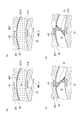
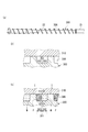
- (a) is a horizontal view showing the flow of molten resin occurring in the screw groove by forward rotation
- (b) is a longitudinal view showing the flow of molten resin occurring in the screw groove by reverse rotation
- (c) is (A)
- (d) is a longitudinal sectional view showing the velocity distribution of the molten resin in the case of (b). It is a figure which shows operation
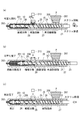
- the injection molding machine 1 includes a mold clamping unit 100, a plasticizing unit 200, and a control unit 50 that controls the operation of these units.
- a mold clamping unit 100 the configuration and operation of the mold clamping unit 100 and the outline of the configuration and operation of the plasticizing unit 200 will be described, and then the procedure of injection molding by the injection molding machine 1 will be described.
- the mold clamping unit 100 is fixed on the base frame 101 and on a sliding member 107 such as a rail or a sliding plate by operating a stationary die plate 105 to which a stationary mold 103 is attached and a hydraulic cylinder 113. And a plurality of tie bars 115 for connecting the fixed die plate 105 and the movable die plate 111 to each other.
- the fixed die plate 105 is provided with a hydraulic cylinder 117 for clamping a die coaxially with each tie bar 115, and one end of each tie bar 115 is connected to a ram 119 of the hydraulic cylinder 117.
- Each of these elements performs a necessary operation in accordance with an instruction from the control unit 50.
- the general operation of the mold clamping unit 100 is as follows. First, the movable die plate 111 is moved to the position of the two-dot chain line in the figure by the operation of the hydraulic cylinder 113 for opening and closing the mold, and the movable mold 109 is brought into contact with the fixed mold 103. Next, the male screw portion 121 of each tie bar 115 and the half nut 123 provided on the movable die plate 111 are engaged to fix the movable die plate 111 to the tie bar 115. Then, the pressure of the hydraulic oil in the oil chamber on the movable die plate 111 side in the hydraulic cylinder 117 is increased, and the fixed mold 103 and the movable mold 109 are tightened. After performing the mold clamping in this way, the molten resin M is injected from the plasticizing unit 200 into the cavity of the mold to form a molded product.
- the screw 10 of this embodiment is a system which supplies the thermoplastic resin pellet P and the reinforcement fiber F separately to the longitudinal direction of a screw so that it may mention later, the full length of the screw 10 or the total length of the plasticizing unit 200 becomes long.
- the present embodiment is configured as described above, which can be installed even in a narrow space where a mold clamping device of a toggle link system or a mold clamping cylinder on the back of a movable die plate cannot be installed.
- the combination of the mold clamping unit 100 having the above is effective for keeping the overall length of the injection molding machine 1 short.
- the configuration of the mold clamping unit 100 shown here is merely an example, and does not prevent other configurations from being applied or replaced.
- the hydraulic cylinder 113 is shown as an actuator for opening and closing the mold in the present embodiment, it may be replaced with a combination of a mechanism that converts rotational motion into linear motion and an electric motor such as a servo motor or an induction motor.
- an electric motor such as a servo motor or an induction motor.
- a ball screw or a rack and pinion can be used.
- it may be replaced with a toggle link type clamping unit by electric drive or hydraulic drive.
- the reinforcing fiber F is used as an additive component.
- the plasticizing unit 200 is supplied with a cylindrical heating cylinder 201, a discharge nozzle 203 provided at the downstream end (front side) of the heating cylinder 201, a screw 10 provided inside the heating cylinder 201, and a reinforcing fiber F. And a resin supply hopper 207 to which resin pellets P are supplied.
- the fiber supply device 213 is connected to a vent hole 206 provided on the downstream side of the resin supply hopper 207.
- the plasticizing unit 200 includes a first electric motor 209 that moves the screw 10 forward or backward, a second electric motor 211 that rotates the screw 10 forward or backward about the rotation axis, and a resin pellet P with respect to the resin supply hopper 207.
- a pellet supply device 215 for supplying.
- Each of these elements performs a necessary operation in accordance with an instruction from the control unit 50.
- a load cell (not shown) is interposed between the downstream end (rear end) of the screw 10 and the first electric motor 209, and the load received by the screw 10 in the axial direction can be detected.
- the plasticizing unit 200 by the electric motor controls the back pressure of the screw 10 during plasticization based on the load detected by the load cell.
- the load detected by the load cell is used for a purpose different from the control of the back pressure. This point will be described later.
- the screw 10 has a two-stage design similar to a so-called gas vent type screw. Specifically, the screw 10 includes a first stage 21 provided on the upstream side and a second stage 22 connected to the first stage 21 and provided on the downstream side, and the first stage 21 is sequentially supplied from the upstream side.
- the second stage 22 includes a supply unit 25, a compression unit 26, and a measurement unit 71 in order from the upstream side. In the drawing, the right side is the upstream side, and the left side is the downstream side.
- a first flight 27 is provided on the first stage 21, and a second flight 28 is provided on the second stage 22.
- the screw grooves between the flights in the supply units 23 and 25 are relatively deep, and the screw grooves between the flights of the compression units 24 and 26 are gradually reduced from the upstream side toward the downstream side.
- the screw grooves in the weighing units 70 and 71 are set to be the shallowest.
- the screw groove of the supply unit 25 of the second stage 22 is deeper than the measuring unit 70 of the first stage 21, the molten resin M discharged from the first stage 21 to the supply unit 25 is screwed into the supply unit 25. Can't fill the groove. Thereby, the molten resin M is pressed against the push side 305 by the rotation of the screw 10 and is unevenly distributed.
- the first flight 27 of the first stage 21 has a flight lead (L1) equal to or less than the flight lead (L2) of the second flight 28 of the second stage 22. That is, it is preferable that L1 ⁇ L2.
- the flight lead (hereinafter simply referred to as “lead”) refers to the interval between adjacent flights.
- the lead L1 of the first flight 27 is preferably 0.4 to 1.0 times, more preferably 0.5 to 0.9 times the lead L2.
- the lead L2 of the second flight 28 of the second stage 22 is larger than the lead L1 of the first flight 27.
- the second stage 22 is supplied with the reinforcing fibers F on the rear end side during the plasticizing process.
- the lead L2 is large, the groove width between the second flights 28 is large, and the gap that can be filled by dropping the reinforcing fibers F becomes large.
- the number of times the vent hole 206 is blocked by the second flight 28 when the screw 10 is retracted during the plasticizing process and when the screw 10 is advanced during the injection process is reduced.
- the lead L2 is preferably 1.0 ⁇ D or more, and further 1.2 ⁇ D or more. It is more preferable. By doing so, the reinforcing fiber F can be stably dropped into the groove of the screw 10 during the injection process.
- D is the inner diameter of the heating cylinder 201.
- the lead L2 is preferably 2.0 ⁇ D or less, and more preferably 1.7 ⁇ D or less. That is, the lead L2 of the second flight 28 is preferably 1.0 ⁇ D to 2.0 ⁇ D, and more preferably 1.2 ⁇ D to 1.7 ⁇ D.
- the width of the flight of the second flight 28 is preferably 0.01 to 0.3 times the lead L2 (0.01 ⁇ L2 to 0.3 ⁇ L2). If the flight width is smaller than 0.01 times the lead L2, the strength of the second flight 28 becomes insufficient. If the flight width exceeds 0.3 times the lead L2, the screw groove width becomes smaller and the fiber is on the top of the flight. This is because it becomes difficult to fall into the groove due to being caught in. Further, in addition to the above-described preferred form in which L1 ⁇ L2 is satisfied, a part or all of the second flights 28 of the second stage 22, particularly the supply unit 25, may be a plurality of flights instead of a single flight.
- the molten resin M discharged from the first stage 21 is divided and distributed into screw grooves partitioned by a plurality of flights, so that the fiber bundle and the molten resin M are respectively in each screw groove. Since they are contacted and mixed, it is effective for impregnating the molten resin M into the fiber bundle. Furthermore, by making the number of flights in the region where the reinforcing fiber F is supplied from the fiber supply device 213 plural, the number of flights under the vent hole 206 per one rotation of the screw 10 by the plural number of flights can be increased. Therefore, the ability to scrape the reinforcing fiber F from the vent hole 206 is improved, and the efficiency of taking the reinforcing fiber F into the screw 10 groove is improved.
- the fiber supply device 213 of this embodiment is provided with a biaxial screw feeder 214 in the heating cylinder 201 to forcibly supply the reinforcing fiber F into the groove of the screw 10.
- a biaxial screw feeder 214 in the heating cylinder 201 to forcibly supply the reinforcing fiber F into the groove of the screw 10.
- continuous fibers that is, so-called roving fibers (hereinafter referred to as roving fibers) may be directly fed into the biaxial screw feeder 214, or a predetermined length may be used in advance. Fibers in a chopped strand state (hereinafter referred to as chopped fibers) that have been cut into lengths may be introduced.
- roving fibers and chopped fibers may be mixed and introduced at a predetermined ratio.
- the chopped fiber When the chopped fiber is introduced, it may be conveyed to the vicinity of the fiber insertion port of the measuring feeder with the roving fiber, and may be input to the measuring feeder immediately after cutting the roving fiber in the vicinity of the fiber input port.
- a roving cutter 218 is provided in the vicinity of the fiber insertion port of the biaxial screw feeder 214. The roving cutter 218 cuts the roving fiber into a chopped fiber, and then supplies the chopped fiber to the biaxial screw feeder 214.
- the general operation of the plasticizing unit 200 is as follows. Please refer to FIG.
- pellets the reinforcing fiber F supplied from the fiber supply device 213 through the vent hole 206 and the thermoplastic resin supplied from the resin supply hopper 207 ( The resin pellet P) is sent out toward the discharge nozzle 203 at the downstream end of the heating cylinder 201.
- the timing for starting the supply of the reinforcing fiber F is preferably after the resin pellet P (molten resin M) supplied from the resin supply hopper 207 reaches the vent hole 206 to which the reinforcing fiber F is supplied. .
- the reinforcing fiber F having poor fluidity and transportability by the screw 10 closes the screw groove, and the molten resin M is transported. This is because the molten resin M may overflow from the vent hole 206 and abnormal wear or damage of the screw 10 may occur.
- a predetermined amount is injected into a cavity formed between the fixed mold 103 and the movable mold 109 of the mold clamping unit 100.
- the basic operation of the screw 10 is that the injection is performed by moving forward after the screw 10 is moved backward while receiving the back pressure as the resin pellet P melts.
- other configurations such as providing a heater for melting the resin pellets P on the outside of the heating cylinder 201 are not prevented from being applied or replaced.
- the injection molding machine 1 including the above elements performs injection molding according to the following procedure.
- the injection molding is performed by closing the movable mold 109 and the fixed mold 103 and clamping at a high pressure, and plasticizing the resin pellet P by heating and melting in the heating cylinder 201.
- a plasticizing step an injection step of injecting and filling the plasticized molten resin M into a cavity formed by the movable mold 109 and the fixed mold 103, and until the molten resin M filled in the cavity is solidified.
- a holding process to cool, a mold opening process to open the mold, and a take-out process to take out the molded product that has been cooled and solidified in the cavity are carried out, and the above-mentioned processes are performed sequentially or partially in parallel. Thus, one cycle of injection molding is completed.
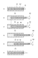
- the screw 10 is reversed during the plasticizing process, and the operation is performed with reference to FIG. 3 after the description of the injection process.
- the resin pellet P is supplied from the supply hole 208 corresponding to the resin supply hopper 207 on the upstream side of the heating cylinder 201.
- the screw 10 at the beginning of plasticization is located downstream of the heating cylinder 201, and is retracted while rotating the screw 10 from the initial position (FIG. 2 (a) "Begin plasticization").
- the resin pellet P supplied between the screw 10 and the heating cylinder 201 is gradually melted while being heated by receiving a shearing force, and is conveyed downstream.
- the rotation (direction) of the screw 10 in the plasticizing step is assumed to be normal rotation.
- the reinforcing fiber F is supplied from the fiber supply device 213.
- the reinforcing fibers F are kneaded and dispersed in the molten resin M, and are conveyed downstream together with the molten resin M.
- FIG. 2 shows the states of resin (resin pellet P, molten resin M) and reinforcing fiber F in four stages of “unmelted resin”, “resin melt”, “fiber dispersion”, and “fiber dispersion complete”. ing.
- fiber dispersion completion downstream of the screw 10 indicates a state in which the reinforcing fibers F are dispersed in the molten resin M and used for injection, and “fiber dispersion” It shows that the supplied reinforcing fiber F is dispersed in the molten resin M with the rotation of the screw 10.
- reinforcing fiber F may be unevenly distributed in the “fiber dispersion complete” region.
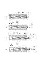
- the screw 10 After performing the first forward rotation only for a predetermined period, as shown in FIG. 3C, the screw 10 is reversely rotated (first reverse rotation, RR1). Thereby, the molten resin M receives the conveyance force toward the upstream different from the time of normal rotation.
- the screw 10 After performing the first reverse rotation for a predetermined period, the screw 10 is rotated forward (second forward rotation, NR2), and the screw 10 is moved back to a predetermined position as shown in FIG.
- second forward rotation, NR2 second forward rotation, NR2
- the screw 10 is reversely rotated (second reverse rotation, RR2). Also at this time, the molten resin M receives an upstream conveying force different from that during normal rotation.
- the predetermined period during which the first normal rotation and the second normal rotation are performed is a predetermined time, for example, even if the time elapsed since the screw 10 started normal rotation reaches a predetermined time.
- the stroke may be a period until the screw 10 rotates forward and moves backward due to the pressure of the molten resin M and reaches a predetermined position or reaches a predetermined amount of backward movement.
- the predetermined period during which the first reverse rotation and the second reverse rotation are performed is a predetermined time, for example, even if the time elapsed since the screw 10 started the reverse rotation reaches a predetermined time.
- It may be a rotation angle, for example, a period from when the screw 10 starts reverse rotation to a predetermined number of rotations or a rotation angle.
- a rotation angle for example, a period from when the screw 10 starts reverse rotation to a predetermined number of rotations or a rotation angle.
- sufficient rotation necessary for opening the reinforcing fiber F is obtained by a predetermined rotational acceleration. It may be accelerated and reversed until the speed is reached.
- the reverse rotation torque necessary to achieve a sufficient reverse rotation speed necessary for opening the reinforcing fiber F is grasped in advance, the reverse operation may be performed until the reverse rotation torque is reached.
- the screw 10 is advanced to perform the injection process. During this time, the screw 10 does not rotate forward or reverse.
- the plasticizing process with reversal of the screw 10 is performed according to the above procedure. Next, the operation and effect of the reversal will be described with reference to FIGS. While the screw 10 is rotating forward NR1, 2, the molten resin M in the screw groove 31 receives a shearing force T1 in the circumferential direction of the screw 10, as shown in FIG. On the other hand, while the screw 10 is rotating in the reverse direction RR1, 2, the molten resin M in the screw groove 31 receives a shearing force T2 along the circumferential direction of the screw 10, as shown in FIG. As will be described later, the shearing force T2 is opposite to the shearing force T1 during forward rotation.
- the shearing force T1 and the shearing force T2 having different directions are applied to the reinforcing fiber F by performing forward rotation and reverse rotation.
- the fiber bundle is unwound by the shearing force in each direction without being biased in one direction, and each time, the phase is changed and the shearing force in a different direction is received.
- the stirring force acts on the fiber bundle to promote the opening.
- a fiber bundle that is a collection of a large number of reinforcing fibers F such as the vicinity of the supply portion of the reinforcing fibers F is divided into the flight pulling side 303, and the molten resin M is divided into the flight pushing side 305.
- the reinforcing fiber bundle moves relative to the flight pushing side 305 from the flight pulling side 303 due to the reverse rotation, so that the molten resin M on the flight pushing side 305 becomes the reinforcing fiber bundle. Since the air flows between the flight pulling side 303 and the fiber bundle of the reinforcing fibers F and enters the inside of the bundle of reinforcing fibers F, the opening of the fiber bundle can be promoted.
- the swirl flow RF of the molten resin M generated along the inner periphery of the heating cylinder 201 of the screw 10 in the screw groove 31 by the reverse rotation of the screw 10 is generated over the entire length of the screw 10. Therefore, the reinforcement which exists in the screw groove
- the vent-up can be suppressed, and the trouble of supply failure of the reinforcing fiber F and the trouble of the biaxial screw feeder 214 due to the molten resin M entering and solidifying into the biaxial screw feeder 214 due to the vent up can be prevented. .
- the reinforced fiber F has the shear force T1 and the shear force T2 with directions opposite to each other. Are alternately received, and fiber opening can be further promoted.
- N rotations the screw 10 is reversely rotated by, for example, 1/3 N rotation (FIG. 12 (a)), stopped (FIG. 12 (b)), / 3N rotation reverse (FIG. 12 (c)), stop (FIG. 12 (d)), 1 / 3N rotation reverse (FIG. 12 (e)), and stop (FIG.
- the screw 10 can be intermittently reversed by dividing the reversal angle.
- This intermittent reversal can be applied to each reversal of the pattern in which a plurality of reversals shown in FIGS. 3A to 3D and FIGS. 6A to 6G are performed.
- the present invention can also be applied to a pattern that performs one reversal shown in (a) to (d).
- the division angles of the predetermined reversal angle in the intermittent reversal may be uniform angles or partially or entirely different angles.
- each reverse rotation speed in the intermittent reverse rotation may be a uniform speed, or a part or all of different speeds (multistage speed).
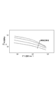
- FIG. 11 shows the relationship between the shear rate of the molten resin and the melt viscosity. The slower the shear rate, the higher the viscosity.
- the molten resin M inside the screw groove 31 is caused to flow
- the moment when the force is applied to reverse the flow direction to the molten resin when the screw 10 shifts from normal rotation to reverse rotation In other words, the molten resin behaves almost like a solid at the moment when a force for changing the flow state including stopping the flow is applied. That is, the behavior at this moment is that the shearing force applied to the surface of the molten resin is not consumed by the deformation of the molten resin, but can be transferred to the reinforcing fibers F inside the molten resin to unravel the fiber bundles of the reinforcing fibers F. .
- a shearing force generated in the molten resin is the product of the melt viscosity value and the shear rate value. As shown in FIG. 11, the shear rate is low when the shear rate is high, and the shear rate is low when the viscosity is high.
- the rotational speed of the screw 10 during this intermittent reverse rotation is not limited to a constant value, and the speed can be switched.
- the speed of the first half of the reverse rotation can be increased and the speed of the second half can be decreased, or vice versa.
- the molten resin behaves like a solid as in the case of applying a shear force to reverse the flow direction described above. Therefore, an effective shearing force and stirring force can be applied to the fiber bundle in the screw groove 31 by changing the speed during the reverse rotation.
- the speed of individual reverse rotation can be changed such as high speed, low speed, high speed, low speed, and so on. Further, when the screw 10 is reversely rotated intermittently, the reverse rotation can be continuously or intermittently performed until reaching the above-described sufficient rotational speed or rotational torque required for opening the reinforcing fiber F.
- the screw 10 can be forcibly retracted during the plasticizing process.
- the screw 10 is only rotated forward, and the screw 10 is retracted while receiving back pressure by the resin pressure of the molten resin M conveyed downstream along with the normal rotation.
- the screw 10 is forcibly retracted by the operation of the first electric motor 209 regardless of the resin pressure. This forcible retraction is faster than the retraction due to the resin pressure, and is set, for example, at least twice the retraction speed due to the resin pressure.
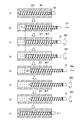
- FIG. 6 the operation of the screw 10 of the present embodiment involving forced retraction will be described.
- the forcible retraction of the screw 10 may be performed not until the stroke D1 is retreated, but until a counter such as a timer starting from a predetermined timing is counted up, or by combining the stroke D1 and the counter counting up. Also good.
- the void S1 expands when the pressure is lower than that in the molten resin M. Formed.
- the pressure of the molten resin M is increased by the screw and is pushed into the molten resin M again.
- the screw 10 is forwardly rotated at the first retracted position (first forward rotation, NR1), whereby the molten resin M is conveyed downstream and formed first as shown in FIG. 6C.
- the filled gap S1 is replenished.
- the screw 10 is reversed (first reverse rotation, RR1) for a predetermined period. Whether or not the gap S1 is filled with the molten resin M can be detected by the load cell described above. In other words, when the gap S1 is filled from the state where the gap S1 is present, the screw 10 receives a load from the molten resin M. Therefore, by detecting this load via the screw 10, the gap S1 is filled with the molten resin M. Can be detected.
- the screw 10 is reversely rotated triggered by this detection.
- the detection that the gap S1 is filled with the molten resin M is not limited to the load cell, and other means can be applied.
- the screw 10 may be retracted by a minute amount. Therefore, the fullness can be detected by detecting this displacement. Further, by providing a pressure gauge that penetrates the heating cylinder 201 and communicates with the inside of the heating cylinder 201, fullness can be detected.
- the screw 10 is reversely rotated for a predetermined period, the screw 10 is forcibly moved backward (second backward movement, FB2) by the stroke D1, similarly to the first backward movement. This process is shown in FIGS. 6 (d) and 6 (e).
- a gap S 2 in which no molten resin M exists is formed downstream from the tip of the screw 10. .
- the position of the screw 10 at this time is referred to as a second retracted position, and the second retracted position coincides with the position (metering position) of the screw 10 at which the amount of molten resin M necessary for one shot is measured.
- the screw 10 is retracted to the measuring position by performing the forced retraction twice with the same stroke.
- the forcible retraction stroke of the screw 10 may be the same stroke or different strokes in the first retraction and the second retraction.
- the speed of the forced retraction of the screw 10 may be the same speed in the first retraction and the second retraction, or may be different speeds.
- the first retraction continues without stopping the rotation of the screw 10 even if the detection method described later detects that the gap S1 is filled with the molten resin M due to the rotation of the screw 10 at the first retraction position.
- the screw 10 Based on the pressure of the molten resin M or at a predetermined speed, the screw 10 is moved backward by a predetermined stroke, a predetermined time, or any combination of the predetermined stroke and a predetermined time, and then the screw 10 is moved to the second retracted position. You may be forced to retreat up to.
- the sufficient retraction speed necessary for opening the reinforcing fiber F is grasped in advance by experiment or numerical analysis
- the sufficient retreat necessary for opening the reinforcing fiber F is achieved by a predetermined retraction acceleration.
- the vehicle may be accelerated and moved backward until the speed is reached.
- the retraction operation may be performed until the forced retraction force is reached.
- the screw 10 is forwardly rotated at the second retracted position (second forward rotation, NR2), whereby the molten resin M is conveyed downstream and formed first as shown in FIG. 6 (f).
- the gap S2 is replenished.
- the screw 10 is reversely rotated (second reverse rotation, RR2) as shown in FIG. If the second reverse rotation is performed for a predetermined period, the injection process is performed by moving the screw 10 forward as shown in FIG.
- the screw 10 is forcibly retracted FB1 and FB2, as shown in FIG. 7A, the molten resin M in the screw groove 31 is sheared T3 along the rotation axis C of the screw 10. Receive.
- This shearing force T3 works as a force for opening the bundle of reinforcing fibers F.
- FIG. 7B when the screw 10 is forcibly retracted (FB1, 2), the molten resin M adhering to the bottom surface 31A of the screw groove 31 has a velocity V3.
- a relative speed ⁇ V3 is generated in the molten resin M adhering to the inner wall surface 201A. Due to this relative speed difference, as shown in FIG.
- a shearing force T ⁇ b> 3 is generated in the molten resin M along the direction of the rotation axis C of the screw 10, that is, the groove width direction of the screw groove 31.
- the molten resin M adhering to the inner wall surface 201 ⁇ / b> A of the heating cylinder 201 is scraped off at the top of the second flight 28 on the pulling side (left side in the drawing), and along the pulling side surface 28 ⁇ / b> A of the second flight 28. And flows into the screw groove 31.
- the shearing force is applied to the reinforcing fiber F over the entire groove direction of the screw groove 31.
- the length direction of the reinforcing fibers F acts as a force for opening the bundle of reinforcing fibers F arranged in the circumferential direction or the bundle of reinforcing fibers F having a small angle with the circumferential direction.
- a fiber bundle that is a collection of a large number of reinforcing fibers F such as the vicinity of the supply portion of the reinforcing fibers F is divided into the flight pulling side 303, and the molten resin M is divided into the flight pushing side 305.
- the molten resin M by the swirl flow RF flows between the flight pulling side 303 and the fiber bundle of the reinforcing fibers F and enters the inside of the bundle of reinforcing fibers F.
- the reinforcing fiber F receives the shearing force T1 in the groove width direction, the shearing force T2 opposite to the shearing force T1, and further receives the shearing force T3. Is more promoted.
- the molten resin M flows backward in the direction opposite to that during forward rotation, that is, the screw 10 side.
- the wall surface W1 and the wall surface W2 flow toward the screw 10, and the boundary surface between the wall surface W1 and the wall surface W2 is disturbed. Due to the disturbance of the boundary surface, the bubbles b are deformed, subdivided, and refined.
- the torsional force P is applied to the boundary surface W between the wall surface W1 and the wall surface W2, so that the bubbles b are dispersed in the surrounding molten resin M by these behaviors. Can do.
- the forced retraction pattern described above is an example of the present invention, and a plasticizing process including forced retraction can be performed with other patterns.
- the screw 10 can be displaced to the measuring position by performing the forced backward FB once.
- FIGS. 10A to 10D when the forced retraction is performed by a predetermined stroke D1, the screw 10 is retreated, stopped by 1/3 ⁇ D1, for example (FIG. 10B), and retreated. , Stop (FIG. 10C)..., The screw 10 can be retracted intermittently by dividing the predetermined stroke D1.
- This intermittent forcible retraction can be applied to each forcible retraction of a pattern in which the screw 10 is displaced to the measuring position by performing a plurality of forcible retractions shown in FIGS. 6 (a) to 6 (e).
- 9A to 9B can be applied to a pattern in which the screw 10 is displaced to the measuring position by performing the one-time forced retraction shown in FIGS.
- each reverse speed in the intermittent forced reverse may be a uniform speed or a partly or entirely different speed (multistage speed).
- This intermittent forced retreat can be expected to further promote the opening of the reinforcing fiber F. That is, FIG. 11 shows the relationship between the shear rate of the molten resin and the melt viscosity. The slower the shear rate, the higher the viscosity. Assuming that the molten resin M inside the screw groove 31 is caused to flow, the molten resin is almost solid at the moment when a force is applied to cause the molten resin to flow from a state where there is no flow. Behave.
- the behavior at this moment is that the shearing force applied to the surface of the molten resin is not consumed by the deformation of the molten resin, but can be transferred to the reinforcing fibers F inside the molten resin to unravel the fiber bundles of the reinforcing fibers F. . Furthermore, by continuously applying a shearing force to the molten resin, a high shearing force is applied to the fiber bundle due to a high viscosity state in the low shear rate region during acceleration, and a flow is generated in the molten resin, resulting in a broken fiber. Since the stirring effect can be added to the bundle, the opening of the fiber bundle can be promoted.
- the shearing force generated in the molten resin is the product of the melt viscosity value and the shear rate value. As shown in FIG. 11, the shear rate is low when the shear rate is large, and the shear rate is small when the viscosity is high. Therefore, in order to obtain a large shearing force, it is necessary to have a condition where the viscosity and shear rate are large in a balanced manner, but not only the melt viscosity shear rate but also the material resin type and resin temperature are greatly affected. Ascertaining the conditions under which the viscosity and speed increase in a well-balanced manner requires knowledge of the resin properties and is complicated and not easy.
- intermittent forced retraction is performed to continuously change from low speed to high speed during acceleration of forced retraction, so that a shear force field based on a combination of viscosity and shear rate is continuously applied to the molten resin.
- the conditions under which a high shear force can be obtained can be achieved.
- a forced retreat condition in which a large shear force effective for opening the reinforcing fiber F can be applied. Therefore, by increasing the number of times of movement, effective shearing force and stirring force can be repeatedly applied to the fiber bundle in the screw groove 31, so that the degree of fiber bundle opening can be increased.
- the speed of the screw 10 at the time of intermittent forcible retreat is not limited to a constant value, and the speed can be changed.
- the speed can be changed.
- the molten resin behaves like a solid as in the case of applying a shearing force to the stationary state described above.
- effective shearing force and stirring force can be applied to the fiber bundle in the screw groove 31.
- the individual retreating speed can be changed such as high speed, low speed, high speed, low speed, and so on.
- the retreat control is performed continuously or intermittently until reaching the above-described sufficient retraction speed or forced retraction force necessary for opening the reinforcing fiber F. You can also.
- the rotation of the screw 10 is stopped at the time of forced retraction, but it may be forced to retreat while the screw 10 is rotating forward. In this case, it is possible to perform normal rotation over the entire period during which the force is retracted, and it is possible to perform normal rotation only during a part of the period during which the force is retracted. Further, the forward rotation of the screw 10 for filling the space S1 or the space S2 after the forced retraction is performed at the first retraction position or the second retraction position. The screw for filling the space S1 or the space S2 is performed. The forward rotation of 10 can be performed while moving forward.
- the gap S1 or the gap S2 can be reduced by the molten resin resulting from the forward rotation of the screw 10, and at the same time, the gap S1 or the gap S2 can be reduced by advancing the screw 10 at the same time.
- the forward speed of the screw 10 at this time may be a forward speed comparable to the backward speed of the screw 10 due to the pressure of the resin, that is, a low speed that does not reach a sufficient moving speed necessary for fiber opening.
- FIG. 15 shows a screw reverse speed setting screen which is a man-machine interface of the control device of the injection molding machine used in this experiment. This screen allows the molding operator to compare other plasticization conditions (set values and run values), especially the amount of molten resin that fills the mold with the metering screw position to meter by retraction of the screw.
- the screw reverse rotation speed setting unit that can input the reverse rotation speed of the screw at an arbitrary value and a plurality of reverse rotation operation interval setting units that set a switching position for setting the operation interval of the reverse rotation operation are arranged. .
- the reverse rotation speed setting section and reverse rotation operation section setting section allow the molding operator to complete other plasticization conditions (set values and execution values), in particular to measure the amount of molten resin to be filled in the mold by retraction of the screw. It is provided so that it can be compared with the screw position.
- a plurality of reverse rotation speed setting units are provided in an arrangement corresponding to each reverse rotation operation section so that the reverse rotation speed can be set for each of the plurality of reverse rotation operation sections.
- only one reverse rotation speed setting unit may be arranged. In FIG.
- the reverse rotation speed setting section and the reverse rotation operation section setting section are arranged in the screen for setting the plasticization conditions (plasticization condition setting screen).
- the reverse rotation speed setting section and the reverse rotation operation section setting section may be provided on the screen or another input device provided in a different part. Further, a changeover switch for switching between control for performing plasticizing and measuring by performing a reverse operation and control for plasticizing and measuring without performing a reverse operation may be provided.
- the operation condition setting unit of the raw resin supply device and the reinforcing fiber supply device may be arranged so as to be compared with the reverse rotation speed setting value and the reverse rotation operation section setting value.
- FIG. 15 shows a screen in which each reverse operation section can be individually set by the operator, but when the reverse operation and the screw normal operation are alternately turned back, when each reverse operation section may be equally divided, Alternatively, when the distribution may be performed in a predetermined pattern or ratio, each reverse operation section may be automatically calculated and set by simply inputting the number of divisions.
- an acceleration setting unit that can input the acceleration of the reverse rotation operation with an arbitrary value may be provided on this screen.
- FIGS. 14 (a) and 14 (b) show the surface of a fiber reinforced resin (conventional example) molded without reversing
- FIG. 14 (b) shows the forced retreat in the patterns shown in FIGS. 3 (a) to 3 (f).
- molded by performing is shown.
- FIG. 14A in the conventional example, there are many reinforcing fibers F in a bundle, and these appear as black dots on the surface of the molded product.
- FIG. 14 (b) in the example, there are almost no reinforcing fibers F with poor opening that are bundled, so black spots as in the conventional example are on the surface. Not appearing.
- the reinforcing fiber F when the rotation amount [mm] of the reverse operation is less than ⁇ ⁇ D ⁇ (10 ° (reverse rotation angle) / 360 °) [mm] or 10 [mm], whichever is smaller, the reinforcing fiber F In some cases, the fiber opening was not sufficient. This is a strengthening that is entangled in the screw groove when the rotation amount of the reverse operation is less than ⁇ ⁇ D ⁇ (10 ° (reverse rotation angle) / 360 °) [mm] or 10 [mm], whichever is smaller. It is considered that the fiber F cannot be stretched by a sufficient distance, so that the reinforcing fiber F bent and deformed by entanglement cannot be separated simply by extending, and the entanglement cannot be broken and opened.
- the rotation amount of the reverse rotation operation of the screw 10 is equal to or larger than the rotation amount of ⁇ ⁇ D ⁇ (10 ° (reverse rotation angle) / 360 °) [mm] or 10 [mm], whichever is smaller.
- the rotation amount of the reverse rotation operation is preferably equal to or larger than the rotation amount of ⁇ ⁇ D ⁇ (20 ° (reverse rotation angle) / 360 °) [mm] or 20 [mm], whichever is smaller.
- the rotation amount of the reverse rotation operation is preferably 10 times or less, more preferably 5 times or less, as the number of rotations (number of screw rotations).
- the rotation amount of the reverse rotation operation of the screw 10 is preferably greater than or equal to the smaller stroke of ⁇ ⁇ D ⁇ (10 ° (reverse rotation angle) / 360 °) [mm] or 10 [mm] Further, the number of rotations of the reverse operation is preferably 10 or less. More preferably, the rotation amount of the reverse operation is ⁇ ⁇ D ⁇ (20 ° (reverse rotation angle) / 360 °) [mm] or 20 [mm], which is the smaller rotation amount and not more than 5 rotations. The range of is most preferable.
- the outer peripheral speed of the screw 10 in the reverse operation is equal to or higher than 50 [mm / s] or 0.5 ⁇ D [mm / s] (D is the cylinder inner diameter), whichever is smaller. It came to know that the effect of can be obtained effectively.
- the shearing force applied from the molten resin M to the reinforcing fiber F is proportional to the product of the viscosity of the molten resin M and the shear rate (deformation rate), the speed applied to the molten resin M is high. As the value increases, the shearing force acting as the opening force on the reinforcing fiber F increases. When the peripheral speed is less than 50 [mm / s] or 0.5 ⁇ D [mm / s], whichever is smaller, a sufficient shear force is applied to the reinforcing fibers F entangled in the screw groove. Unable to unravel the fiber bundle.
- the fiber bundles cannot be broken and entangled to be opened only by causing a deviation between the entangled fiber bundles or by gently deforming the fiber bundle.
- the speed of the swirling flow RF (V3, -V3) is substantially the same as the screw reverse rotation speed, so that the speed of the swirling flow RF in the screw groove (V3, -V3) is 50 [mm / s] or 0.5 ⁇ D [mm / s], whichever is smaller, is considered to be effective for opening the reinforcing fiber F.
- the reinforcing fiber F may not be sufficiently opened. This is easily deformed when the change in the molten resin M shear rate is slow, and therefore when the acceleration of the reverse operation is small (less than 50 (mm / s2)), the molten resin M interposed between the fiber bundles is moderate. This is because the shearing force is consumed by the deformation of the molten resin M and the fiber bundle is not effectively opened. Therefore, it is preferable that the acceleration of the reverse operation is 50 (mm / s2) or more.
- the acceleration of the reverse operation is preferably 100 (mm / s2) or more, and more preferably 200 (mm / s2) or more. In the case where the backward movement was performed at an acceleration of 200 (mm / s2) or more, the opening failure of the reinforcing fiber F did not occur under any of the experimental conditions.
- the acceleration distance (circumferential direction) of the reverse operation is less than the smaller rotation amount of ⁇ ⁇ D ⁇ (10 ° (reverse rotation angle) / 360 °) [mm] or 10 [mm]. preferable.
- the lower limit value of the rotation amount at which the effect of the present invention is obtained is the smaller rotation amount of ⁇ ⁇ D ⁇ (10 ° (reverse rotation angle) / 360 °) [mm] or 10 [mm]. is there. From this, if the rotation amount of ⁇ ⁇ D ⁇ (10 ° (reverse rotation angle) / 360 °) [mm] or 10 [mm], whichever is smaller, is required for acceleration, the reinforcing fiber F is opened.
- the section where the reversing operation is effective at a fine reversing speed ends in an instant. Therefore, depending on the raw material resin, it may not reach a level that satisfies the molding quality required by the user.
- the present invention has been described based on the embodiments.
- the configuration described in the above embodiments may be selected or changed to other configurations as appropriate without departing from the gist of the present invention. is there.
- the pattern of the reverse operation four types of reverse operation of the reverse operation combined with the basic reverse operation, the intermittent reverse operation, the bubble processing, and the forced retraction of the screw 10 are shown.
- a plurality of reverse operation patterns may be combined in an arbitrary order to perform the reverse operation.
- the screw 10 of the injection molding machine to which the present invention is applied is not limited to the two-stage design shown in the present embodiment, and further includes a supply unit, a compression unit, and a metering unit on the downstream side of the second stage.
- a three-stage design with a third stage can be used.
- a function of adding a functional member to the molten resin or degassing volatile substances may be added to the third stage.
- the present invention is applied to a plasticizing unit that uses a single-stage screw 10 having one supply portion, one compression portion, and one weighing portion, and supplies resin pellets P and reinforcing fibers F from the same hopper. You can also Further, the present invention can be applied to an injection molding machine called a pre-plater system that includes a plasticizing device and an injection device each having a screw.
- the resin pellets P and the reinforcing fibers F are plasticized by a plasticizer, and are sent to the plunger of the injection device, and then the plunger is advanced to perform injection molding.
- the present invention can be applied to a plasticizing device of this pre-plastic injection molding machine.
- the preplasticizer plasticizing device is not usually structured or controlled so that the screw can move forward and backward, but when applying the present invention in a pattern in which forced retraction of the screw is combined with screw reversal, Also in the plasticizing apparatus, the structure and control are such that the screw can move forward and backward.
- the fiber supply device 213 and the resin supply hopper 207 are fixed to the heating cylinder 201, but it can be a movable hopper that moves in the axial direction of the screw 10.
- a multi-axis type measuring feeder is used for the fiber supply device 213, a plurality of feeders are connected in parallel in the longitudinal direction of the screw 10, and the feeder for supplying the reinforcing fiber F is switched and used in the plasticizing process. May be.
- the reinforcing fiber F is supplied from a feeder arranged on the tip side of the screw 10 and the screw 10 and the fiber are discharged as the screw 10 moves backward in the plasticizing process.
- the feeder for supplying the reinforcing fibers F may be sequentially switched to the rear side so that the relative position with the feeder screw does not change. Thereby, the supply position of the reinforcing fiber F to the screw 10 can be made constant regardless of the change in the relative position of the heating cylinder 201 and the screw 10 due to the backward movement of the screw 10 and the advancement of the screw 10 at the time of injection.
- the position of the fiber supply feeder screw when plasticization is completed that is, the position of the last screw groove filled with the reinforcing fiber F, is moved to the next plasticization at the screw position advanced by injection. Since it can be made to coincide with the position of the fiber supply feeder screw at the start, the reinforcing fiber F can be continuously supplied to the screw groove downstream from the fiber supply device 213, and in the groove of the screw 10 downstream from the fiber supply device 213. This is effective for preventing or suppressing the generation of the region not filled with the reinforcing fiber F.
- the switching method of the feeder screw may be simple ON / OFF control, or the rotation speed of adjacent screw feeders may be changed in cooperation. Specifically, as the screw moves backward, the rotational speed of the downstream screw feeder may be gradually decreased and the rotational speed of the rear screw feeder may be gradually increased.
- the supply of the reinforcing fiber F to the heating cylinder 201 may be performed not only in the injection process and the plasticizing process, but also in, for example, a pressure holding process and an injection standby process (from the completion of the plasticizing process to the start of the injection process).
- a pressure holding process and an injection standby process from the completion of the plasticizing process to the start of the injection process.
- the screw 10 does not rotate and move forward or backward, so that the vent hole is not intermittently blocked by the movement of the flight. For this reason, the reinforcing fiber can be stably supplied into the groove of the screw 10.
- the reinforcing fiber F not only the reinforcing fiber F but also the reinforcing fiber F mixed with a raw material resin in the form of powder or pellets may be supplied to the fiber supply device 213.
- the mixed raw resin melts in the bundle of the reinforcing fibers F, and enters the fiber bundle to facilitate the opening of the fiber bundle.
- the resin and reinforcing fiber applied to the present invention are not particularly limited, and are known resins such as general-purpose resins such as polypropylene and polyethylene, engineering plastics such as polyamide and polycarbonate, and glass fibers and carbon fibers. Widely includes known materials such as known reinforcing fibers such as bamboo fiber and hemp fiber.
- a fiber reinforced resin having a high content of reinforcing fibers of 10% or more. However, if the content of the reinforcing fiber exceeds 70%, the conveyance resistance of the reinforcing fiber in the screw groove increases.
- the reinforcing fiber can be conveyed. It becomes difficult and the reinforcing fiber may block the inside of the screw groove and cause vent-up at the vent hole. Therefore, the content of the reinforcing fiber applied to the present invention is preferably 10 to 70%, more preferably 15 to 50%. Moreover, the effect of the present invention can be remarkably obtained by molding using a reinforcing fiber having a fiber length of 6 mm or more. Furthermore, it can be remarkably obtained by molding using a chopped fiber having a fiber length of 9 mm or more or a reinforcing fiber in a roving state.
- the quality and value of the molded product can be obtained by uniformly dispersing in the molten resin M such as additives and fillers in place of the reinforcing fibers or in combination with the reinforcing fibers or the resin raw material resin as an additive component.
- the molten resin M such as additives and fillers
- the additive and / or the reinforcing fiber is used instead of or together with the reinforcing fiber from the downstream supply hole.
- a filling material may be supplied.
- an additive and / or a filling substance may be supplied together with the raw material resin from the supply hole on the upstream side of the heating cylinder, and the reinforcing fiber may be supplied from the supply hole on the downstream side.
- an additive and / or a filling substance may be supplied to the heating cylinder instead of the reinforcing fiber or together with the reinforcing fiber, or upstream.
- Additives and / or filler material may be fed to the heating cylinder from both the side and downstream feed holes. Furthermore, by combining these appropriately, for example, the additive is supplied to the heating cylinder by supplying the additive from the supply hole on the upstream side, and the filler material is supplied to the heating cylinder from the supply hole on the downstream side. Also good.
- the additive of the present invention is one that imparts moldability or thermal stability when molding a thermoplastic resin, or improves the durability in an environment where a thermoplastic resin molded product is used. Specifically, stabilizers (antioxidants, thermal degradation inhibitors, hydrolysis inhibitors), light stabilizers, UV absorbers, lubricants, mold release agents, plasticizers, slidability improvers, flame retardants, foaming Agents, antistatic agents, dispersants, nucleating agents, colorants and the like, and these additives can be used alone or in combination of two or more.
- the filling material of the present invention is for improving various properties such as strength, rigidity and heat resistance of a thermoplastic resin molded article, and is usually used.
- glass-based reinforcing agents such as glass beads, glass flakes and glass balloons, silicate-based reinforcing agents such as talc, clay, mica, wollastonite, montmorillonite, magnesium silicate and aluminum silicate, barium sulfate Sulfate reinforcing agents such as calcium carbonate, magnesium carbonate, zinc carbonate, hydroxide reinforcing agents such as aluminum hydroxide, magnesium hydroxide, calcium hydroxide, silica, alumina, titanium oxide, Antioxidant oxide, zinc oxide, magnesium oxide, calcium oxide, silicon oxide and other oxide reinforcing agents, carbon black, graphite, carbon fiber and other carbon reinforcing agents, aluminum, copper, iron, boron, stainless steel fibers, powder and flakes Metal reinforcing agents such as silicon carbide, boron nitride and potassium titanate Chromatography, aluminum borate whisker, coupling agents, acid-modified resin binder agent, a rubber component, etc.
- silicate-based reinforcing agents such
- these filler materials can be used alone or in combination of two or more.
- the time for the additive component to receive heat in the screw groove can be shortened.
- Even low heat-resistant additive components such as pulp, paper waste, waste paper and wool can be uniformly dispersed in the molten resin while suppressing thermal deterioration.
Landscapes
- Engineering & Computer Science (AREA)
- Mechanical Engineering (AREA)
- Manufacturing & Machinery (AREA)
- Injection Moulding Of Plastics Or The Like (AREA)
Abstract
Description
しかしながら、この原料直接供給式の射出成形機においては、添加成分の熱可塑性樹脂中への分配混合及び分散混合が不十分であるため、これを改善した射出成形機が提案されている(特許文献1)。
また、添加成分のうち特に強化繊維による強度向上の効果を得るためには、強化繊維が樹脂の中に均一に分散していることが望まれる。特に、強化繊維に樹脂原料を含浸した強化繊維ペレットを用いるのではなく、予め所定長さに切断されたチョップドストランド状態の繊維(以下、チョップド繊維という)またはいわゆるロービング状態の繊維(以下、ロービング繊維という)で繊維長が3mm以上である強化繊維と樹脂原料とをそれぞれシリンダに供給する場合、繊維がスクリュ内で絡み合いやすく、強化繊維の集合である繊維束を開繊し繊維を樹脂内に分散させることが容易でない。このため、添加成分の均一分散を果たすためには、2軸押出機を用いて、非常に大きなせん断力及びせん断量を与えればよいが、2軸押出機は非常に高価であるとともに、成形条件選定や保全などの取り扱いが煩雑であり、成形が容易ではない(特許文献1および特許文献2)。また、強化繊維の均一分散に寄与するために、シリンダの内部に強化繊維を強制的に供給する機構(フィーダー)を設けることも行われているが(例えば、特許文献3)、強化繊維の束又は塊(以下、束と総称)を解消するには至っていない。特に強化繊維の含有量が10%以上と高含有率の場合、強化繊維を樹脂中に均一に分散させることは困難となっている。
また、本発明は、そのような射山成形方法を実現する射出成形装置を提供することを目的とする。
本発明の射出成形方法において、添加成分は、強化繊維とすることができる。
本発明の可塑化工程において、逆転動作を所定の回転角度または所定の時間を分割して、連続的に、又は、断続的に、スクリュを逆転させることができる。
本発明の可塑化工程において、逆転動作を少なくとも所定の逆転速度あるいは所定の逆転トルクに到達するまで継続することができる。この場合、逆転開始から所定の逆転速度に達するまでの時間、逆転角度を所定値以上または加速度を所定値以上に制御することができる。
また、本発明の可塑化工程において、少なくとも所定の逆転速度あるいは所定の逆転トルクに到達するまで継続する逆転動作を、連続的に、又は、断続的に、行って、スクリュの逆転動作を行うことができる。また、所定の逆転速度あるいは所定の逆転トルクに到達した後の逆転制御は、少なくとも三つの選択肢がある。一つ目の選択肢は、到達と同時に逆転動作を終了するというものであり、二つ目の選択肢は、到達後に所定の逆転速度あるいは所定の逆転トルクを維持しながら逆転動作を継続するというものである。三つ目の選択肢は、到達後にさらに逆転速度を増速あるいは逆転トルクを増大するように制御するというものである。
本発明の可塑化工程において、所定のストロークだけまたは所定の時間だけ、スクリュを強制的に後退させる後退動作を行うことができる。この場合、後退動作と、正転動作と、逆転動作と、を順に行うことができる。また、この場合、後退動作を行うことによりスクリュの前方に形成された、溶融樹脂が存在しない空隙が、正転動作を行うことにより溶融樹脂で充満されたことを検知した後に、逆転動作を行うことができる。また、この後退動作は、所定のストロークあるいは所定の時間を分割して、連続的に、又は、断続的にスクリュを強制的に後退させることができる。
本発明の可塑化工程において、スクリュ停止動作を行う場合には、スクリュを正転させる正転動作と、スクリュ停止動作と、を交互に行うことができる。
また、本発明は、前方側に吐出ノズルが設けられ、添加成分を供給する添加成分供給孔を備えたシリンダと、シリンダの内部に、回転軸を中心にして回転が可能に設けられたスクリュと、スクリュの動作を制御する制御部と、を備え、スクリュを正転させることにより、シリンダに供給された添加成分にせん断力を与えて可塑化し、溶融樹脂を生成する射出成形装置であって、制御部は、可塑化において、スクリュを正転と回転停止を交互に切換える制御プログラムを有するとともに、スクリュの停止条件を任意な値に設定可能な回転停止条件入力設定部を有する制御装置である、ことを特徴とする射出成形機をも提供する。
本実施形態に係る射出成形機1は、図1に示すように、型締ユニット100と、可塑化ユニット200と、これらのユニットの動作を制御する制御部50と、を備えている。
以下、型締ユニット100の構成と動作、可塑化ユニット200の構成と動作の概略について説明し、次いで、射出成形機1による射出成形の手順について説明する。
型締ユニット100は、ベースフレーム101上に固設されるとともに固定金型103が取り付けられた固定ダイプレート105と、油圧シリンダ113を作動させることによってレールや摺動板などの摺動部材107上を図中左右方向に移動するとともに可動金型109が取り付けられた可動ダイプレート111と、固定ダイプレート105と可動ダイプレート111とを連結する複数のタイバー115とを備えている。固定ダイプレート105には、各タイバー115と同軸に型締め用の油圧シリンダ117が設けられており、各タイバー115の一端は油圧シリンダ117のラム119に接続されている。
これらの各要素は制御部50の指示にしたがって必要な動作を行なう。
型締ユニット100の概略の動作は以下の通りである。
まず、型開閉用の油圧シリンダ113の作動により可動ダイプレート111を図中の二点鎖線の位置まで移動させて可動金型109を固定金型103に当接させる。次いで、各タイバー115の雄ねじ部121と可動ダイプレート111に設けられた半割りナット123を係合させて、可動ダイプレート111をタイバー115に固定する。そして、油圧シリンダ117内の可動ダイプレート111側の油室の作動油の圧力を高めて、固定金型103と可動金型109とを締め付ける。このようにして型締めを行った後に、可塑化ユニット200から金型のキャビティ内に溶融樹脂Mを射出して成形品を成形する。
なお、本実施形態は添加成分として強化繊維Fを用いている。
可塑化ユニット200は、筒型の加熱シリンダ201と、加熱シリンダ201の下流端(前方側)に設けた吐出ノズル203と、加熱シリンダ201の内部に設けられたスクリュ10と、強化繊維Fが供給される繊維供給装置213と、樹脂ペレットPが供給される樹脂供給ホッパ207とを備えている。繊維供給装置213は、樹脂供給ホッパ207よりも下流側に設けられているベント孔206に連結されている。
可塑化ユニット200は、スクリュ10を前進又は後退させる第1電動機209と、回転軸を中心にしてスクリュ10を正転又は逆転をさせる第2電動機211と、樹脂供給ホッパ207に対して樹脂ペレットPを供給するペレット供給装置215と、を備えている。これらの各要素は制御部50の指示にしたがって必要な動作を行なう。
スクリュ10の下流側の端部(後端)と第1電動機209の間には、図示を省略するロードセルが介在しており、スクリュ10が軸方向に受ける荷重を検知することができる。電動機による可塑化ユニット200は、ロードセルで検知した荷重に基づいて、可塑化におけるスクリュ10の背圧を制御する。本実施形態においては、背圧の制御とは異なる目的でも、ロードセルで検知した荷重を用いる。この点については、後述する。
スクリュ10は、第1ステージ21に第1フライト27が設けられ、第2ステージ22に第2フライト28が設けられている。
第1ステージ21及び第2ステージ22ともに、相対的に、供給部23,25におけるフライト間のスクリュ溝が深く、圧縮部24,26のフライト間のスクリュ溝が上流側から下流側に向けて漸減していうように設定され、計量部70、71におけるスクリュ溝が最も浅く設定されている。ここで、第1ステージ21の計量部70よりも第2ステージ22の供給部25のスクリュ溝が深いために、第1ステージ21から供給部25に吐出される溶融樹脂Mが供給部25のスクリュ溝を埋め尽くすことができない。これにより、溶融樹脂Mがスクリュ10の回転により押し側305に押しつけられて偏在することになる。これにより第2ステージ22の供給部25の引き側303に空隙が発生する。このためベント孔206を介して繊維供給装置213から供給された強化繊維Fは、この空隙となった引き側303に強化繊維Fが配分されることで、図13に示したように、溶融樹脂Mと強化繊維Fが区分されるものと解される。
この機能を得るために、図1に示すように、第1ステージ21の第1フライト27は、そのフライトリード(L1)が第2ステージ22の第2フライト28のフライトリード(L2)以下とすること、つまりL1≦L2が成り立つことが好ましい。なお、フライトリード(以下、単にリード)とは、前後に隣接するフライトの間隔をいう。一つの指標として、第1フライト27のリードL1は、リードL2の0.4~1.0倍とするのが好ましく、0.5~0.9倍とすることがより好ましい。
また、上述したL1≦L2が成り立つ好ましい形態の他、第2ステージ22の特に供給部25の一部または全部の第2フライト28は、1条フライトではなく、複数条数のフライトでもよい。この場合、第1ステージ21から吐出された溶融樹脂Mが、複数条数のフライトにより区画されたスクリュ溝にそれぞれ分割して分配されるため、各スクリュ溝内で繊維束と溶融樹脂Mがそれぞれ接触、混合されるので、繊維束への溶融樹脂Mの含浸に有効である。またさらに、繊維供給装置213から強化繊維Fの供給を受ける領域のフライト条数を複数にすることにより、複数条数のフライトによってスクリュ10の1回転当たりのベント孔206下のフライトの通過回数が増加するため、強化繊維Fをベント孔206から掻き取る能力が向上し、強化繊維Fのスクリュ10溝内への取り込み効率が向上する。
2軸型スクリュフィーダー214への強化繊維Fの供給方法は、2軸型スクリュフィーダー214に連続繊維、いわゆるロービング状態の繊維(以下、ロービング繊維という)を直接投入してもよいし、予め所定長さに切断されたチョップドストランド状態の繊維(以下、チョップド繊維という)を投入してもよい。あるいは、ロービング繊維とチョップド繊維を所定の割合で混合して投入してもよい。
チョップド繊維を投入する場合は、計量フィーダーの繊維投入口付近までロービング繊維で搬送し、繊維投入口付近でロービング繊維を切断した直後に上記の計量フィーダーに投入してもよい。これにより、飛散しやすいチョップド繊維を成形機投入まで暴露することがないので作業性を向上できる。
本実施形態では、2軸型スクリュフィーダー214の繊維投入口付近に、ロービングカッター218を設ける。ロービングカッター218により、ロービング繊維を切断し、チョップド繊維にしてから2軸型スクリュフィーダー214に供給する。
可塑化ユニット200の概略の動作は以下の通りである。なお、図1を参照願いたい。
加熱シリンダ201の内部に設けられたスクリュ10が回転すると、繊維供給装置213からベント孔206を介して供給された強化繊維F、および、樹脂供給ホッパ207から供給された熱可塑性樹脂からなるペレット(樹脂ペレットP)は、加熱シリンダ201の下流端の吐出ノズル203に向けて送り出される。なお、強化繊維Fの供給を開始するタイミングは、樹脂供給ホッパ207から供給された樹脂ペレットP(溶融樹脂M)が、強化繊維Fが供給されるベント孔206に到達した後とすることが好ましい。溶融樹脂Mがベント孔206に到達する前に強化繊維Fの投入を開始すると、流動性およびスクリュ10による搬送性の乏しい強化繊維Fがスクリュ溝内を閉塞してしまい、溶融樹脂Mの搬送を妨げてベント孔206から溶融樹脂Mがあふれ出したり、スクリュ10の異常摩耗や破損を発生したりするおそれがあるからである。溶融樹脂Mは強化繊維Fと混合された後に、型締ユニット100の固定金型103と可動金型109の間に形成されるキャビティへ所定量だけ射出される。なお、樹脂ペレットPの溶融に伴いスクリュ10が背圧を受けながら後退した後に、前進することで射出を行なうというスクリュ10の基本動作を伴うことは言うまでもない。また、加熱シリンダ201の外側には、樹脂ペレットPの溶融のためにヒータを設けるなど、他の構成を適用し、あるいは置換することを妨げない。
以上の要素を備える射出成形機1は、以下の手順で射出成形を行なう。
射出成形は、よく知られているように、可動金型109と固定金型103を閉じて高圧で型締めする型締工程と、樹脂ペレットPを加熱シリンダ201内で加熱、溶融して可塑化させる可塑化工程と、可塑化された溶融樹脂Mを、可動金型109と固定金型103により形成されるキャビティに射出、充填する射出工程と、キャビティに充填された溶融樹脂Mが固化するまで冷却する保持工程と、金型を開放する型開き工程と、キャビティ内で冷却固化された成形品を取り出す取り出し工程と、を備え、上述した各工程をシーケンシャルに、あるいは一部を並行させて実施して1サイクルの射出成形が完了する。
[可塑化工程]
可塑化工程では、樹脂ペレットPを加熱シリンダ201の上流側の樹脂供給ホッパ207に対応する供給孔208から供給する。可塑化開始当初のスクリュ10は、加熱シリンダ201の下流に位置しており、その初期位置からスクリュ10を回転させながら後退させる(図2(a)「可塑化開始」)。スクリュ10を回転させることで、スクリュ10と加熱シリンダ201の間に供給された樹脂ペレットPは、せん断力を受けて加熱されながら徐々に溶融して、下流に向けて搬送される。なお、本発明では可塑化工程におけるスクリュ10の回転(向き)を正転とする。溶融樹脂Mが繊維供給装置213まで搬送されたならば、強化繊維Fを繊維供給装置213から供給する。スクリュ10の回転に伴い、強化繊維Fは溶融樹脂Mに混錬、分散して溶融樹脂Mとともに下流に搬送される。樹脂ペレットP、強化繊維Fの供給を継続するとともに、スクリュ10を回転し続けると、溶融樹脂Mが強化繊維Fとともに加熱シリンダ201の下流側に搬送され、かつ、スクリュ10よりも下流側に溜まる。スクリュ10の下流に溜まった溶融樹脂Mの樹脂圧力とスクリュ10の後退を抑制する背圧とのバランスによってスクリュ10を後退させる。この後、1ショットに必要な量の溶融樹脂Mが計量され溜まったところで、スクリュ10の回転及び後退を停止する(図2(b)「可塑化完了」)。
射出工程に入ると、図2(c)に示すように、スクリュ10を前進させる。そうすると、スクリュ10の先端部に備えられている図示しない逆流防止弁が閉鎖することで、スクリュ10の下流に溜まった溶融樹脂Mの圧力(樹脂圧力)が上昇し、溶融樹脂Mは吐出ノズル203からキャビティに向けて吐出される。
以後は、保持工程と、型開き工程と、取り出し工程を経て、1サイクルの射出成形が完了し、次のサイクルの型締め工程、可塑化工程が行われる。
本実施形態は、可塑化工程中に、スクリュ10を逆転させる。
通常、可塑化工程においては、スクリュ10を正転させるのみであり、この正転に伴って下流に搬送される溶融樹脂Mの樹脂圧力によって、スクリュ10は背圧を受けつつ後退する。本実施形態においては、正転に加えて、スクリュ10を逆転させる。以下、図3を参照して、詳しく説明する。なお、図3には正転及び逆転を説明するのに必要な要素のみを描いている。
可塑化工程が開始して、スクリュ10を正転(第1正転,NR1)させて、スクリュ10の下流側に溶融樹脂Mが充填される。この過程が、図3(a)と図3(b)に示されており、スクリュ10は所定の位置まで後退する。
所定の期間だけ第1逆転を行った後に、スクリュ10を正転(第2正転,NR2)させ、図3(d)に示すように、スクリュ10を所定の位置まで後退させる。
次に、所定の期間だけ第2正転を行った後に、図3(e)に示すように、スクリュ10を逆転させる(第2逆転,RR2)。このときも、溶融樹脂Mは、正転のときとは異なる上流に向けた搬送力を受ける。このとき第1正転および第2正転を行う所定の期間は、所定時間、例えばスクリュ10が正転を開始してから経過した時間が予め定めた時間に達するまでの期間あっても、所定のストローク、例えばスクリュ10が正転して溶融樹脂Mの圧力によって後退し、所定の位置に到達するまで或いは所定の後退量に到達するまでの期間であってもよい。また、このとき第1逆転および第2逆転を行う所定の期間は、所定時間、例えばスクリュ10が逆転を開始してから経過した時間が予め定めた時間に達するまでの期間あっても、所定の回転角度、例えばスクリュ10が逆転を開始してからの所定の周回数あるいは回転角度に到達するまでの期間であってもよい。また、強化繊維Fの開繊に必要な十分な回転速度の範囲を実験や数値解析により予め把握している場合などは、所定の回転加速度により、強化繊維Fの開繊に必要な十分な回転速度以上に達するまで、加速させて逆転させてもよい。あるいは、強化繊維Fの開繊に必要な十分な逆転速度を成すのに必要な逆転トルクを予め把握している場合は、この該逆転トルク以上に達するまで逆転動作させてもよい。
次いで、スクリュ10を前進させて射出工程を行う。この間、スクリュ10は正転及び逆転しない。
スクリュ10が正転NR1,2している間は、図4(a)に示すように、スクリュ溝31の中の溶融樹脂Mは、スクリュ10の周方向にせん断力T1を受けることになる。一方、スクリュ10が逆転RR1,2している間にも、図4(b)に示すように、スクリュ溝31の中の溶融樹脂Mは、スクリュ10の周方向に沿うせん断力T2を受ける。このせん断力T2は、後述するように、正転時のせん断力T1とは逆向きである。
以上のように、正転と逆転を行うことにより、強化繊維Fに向きの異なるせん断力T1とせん断力T2が加えられる。これにより、一方向に偏ることなく、それぞれの方向のせん断力によって繊維束が解れながらその都度、位相を変えて異方向のせん断力を受けるので、単に正転と逆転をそれぞれ単独で行う場合よりも繊維束には撹拌力が作用して開繊が促進される。また、図13に示すような、強化繊維Fの供給部近傍などの多数の強化繊維Fの集合である繊維束がフライトの引き側303に、また、溶融樹脂Mがフライトの押し側305に分かれて存在する場合には、逆転により強化繊維束がフライトの引き側303からフライトの押し側305の方に相対的に移動するため、フライトの押し側305にあった溶融樹脂Mが、強化繊維束に押し出されて、フライトの引き側303と強化繊維Fの繊維束の間に流れ込むとともに、強化繊維Fの束の内部に入り込むので、繊維束の開繊を促進できる。
一方、図5(b)に示すように、スクリュ10を逆転(RR1,2)させると、正転とは逆向きの速度V2,-V2が生じ、この相対的な速度の差により、図5(d)に示すように、溶融樹脂Mには、せん断力T1とは向きが逆のせん断力T2が生じる。
[断続的な逆転動作]
また、図12に示すように、スクリュ10の逆転を例えばN回転だけ行う際に、スクリュ10を例えば1/3N回転だけ逆転(図12(a))、停止(図12(b))、1/3N回転だけ逆転(図12(c))、停止(図12(d))、1/3N回転だけ逆転(図12(e))及び停止(図12(f))というように、所定の逆転角度を分割して断続的にスクリュ10を逆転させることができる。この断続的な逆転は、図3(a)~(d)および図6(a)~(g)に示した複数回の逆転を行うパターンの各逆転にも適用することができるし、図9(a)~(d)に示した1回の逆転を行うパターンにも適用することができる。また、この断続的な逆転での所定逆転角度の分割角度は、それぞれ均一な角度でも、一部あるいは全部が異なる角度でもよい。また、この断続的な逆転での各逆転速度は均一な速度でも、一部あるいは全部が異なる速度(多段速度)でもよい。さらに、ここでは、逆転と停止を交互に繰り返す例を図示しているが、正転と停止を交互に繰り返しても、正転による溶融樹脂Mの流れの状態を変化させることができる。もちろん、本発明は、正転動作、逆転動作及び停止動作を任意の組合せで行うことができる。
この断続的な逆転により、強化繊維Fの開繊をより促進することが期待できる。つまり、図11に溶融樹脂のずり速度と溶融粘度の関係を示すが、ずり速度が遅いほど粘度が高い。スクリュ溝31の内部の溶融樹脂Mに流動を起こさせる場合を想定すると、スクリュ10が正転から逆転に移行する際の溶融樹脂に流れの方向を逆方向にさせる為に力を負荷した瞬間、つまり流れを停止させることを含む流れの状態を変える力を負荷した瞬間は、溶融樹脂はほぼ固体のような振る舞いをする。つまりこの瞬間の挙動は溶融樹脂の表面に負荷された剪断力が溶融樹脂の変形に消費されることなく、溶融樹脂内部の強化繊維Fに伝達されて強化繊維Fの繊維束を解きほぐすことができる。さらに、継続して溶融樹脂に剪断力を負荷することで、加速途中の低ずり速度域の高粘度状態により繊維束に高い剪断力を加えるとともに、溶融樹脂の流れを発達させて、解れた繊維束に攪拌効果を加えられるので、繊維束の開繊を促進することができる。
また、溶融樹脂に発生する剪断力は、溶融粘度値とずり速度値の積であるが、図11に示すとおりにずり速度が大きいときは粘度が低く、粘度が高いときはずり速度が小さい。よって大きな剪断力をえるためには粘度とずり速度がバランス良く大きな値となる条件が必要であるが、溶融粘度はずり速度のみでなく、原料樹脂種類や樹脂温度にも大きく影響を受けるため、粘度と速度がバランス良く大きくなる条件を把握することは、樹脂物性の知見が必要であると共に煩雑であり容易ではない。しかし、断続的な回転停止やそれに続く逆転あるいは正転を行うことにより逆転あるいは正転の加速途中において、低速から高速まで連続的に変化させるので、連続的に幅広く粘度とずり速度の組合せによる剪断力場を溶融樹脂に負荷して、高剪断力が得られる条件を成し得ることができる。これにより樹脂物性の知見が無くても、強化繊維Fの開繊に有効な大きな剪断力を負荷できる強制後退条件を実施することができる。
したがって、この動き出しの回数を増やすことにより、スクリュ溝31内の繊維束に有効なせん断力と攪拌力を繰り返し加えられるので、繊維束の開繊度合いを大きくすることができる。
また、断続的にスクリュ10を逆転させる場合に、高速、低速、高速、低速…というように、個々の逆転の速度を変えることができる。
また、断続的にスクリュ10を逆転させる場合に、前述した強化繊維Fの開繊に必要な十分な回転速度以上あるいは回転トルク以上に達するまで逆転を連続的にあるいは断続的に行うこともできる。
本実施形態は、可塑化工程中に、スクリュ10を強制的に後退させることができる。
通常、可塑化工程においては、スクリュ10を正転させるのみであり、この正転に伴って下流に搬送される溶融樹脂Mの樹脂圧力によって、スクリュ10は背圧を受けつつ後退する。本実施形態においては、この樹脂圧力によらず、第1電動機209の動作により、スクリュ10を強制的に後退させる。この強制的な後退は、樹脂圧力による後退に比べて、後退する速度が速く、例えば樹脂圧力による後退の速度の2倍以上に設定される。以下、図6を参照して、強制後退を伴う本実施形態のスクリュ10の動作について説明する。
なお、ここでは、スクリュ10が途中で停止することなく連続的にストロークD1だけ後退するものとし、また、強制的に後退する間、スクリュ10は回転が止まっているものとする。ただし、強制後退を行っている最中に、スクリュ10を正転させることもできる。また、スクリュ10の強制後退はストロークD1だけ後退するまでではなく、所定のタイミングからスタートするタイマーなどのカウンターがカウントアップするまで行ってもよし、あるいはストロークD1とカウンターのカウントアップを組み合わせて行ってもよい。
また、この空隙S1は、溶融樹脂Mの中に含まれていた主に揮発成分からなるガス成分が漏れでできたことに加えて、溶融樹脂Mの中よりも低圧になったことで膨張して形成される。この空隙S1を占めるガス成分は、次の第1正転を行うと、スクリュにより溶融樹脂Mの圧力が上昇して、再度、溶融樹脂Mの中に押し込まれる。
空隙S1が溶融樹脂Mで充満されたならば、スクリュ10を所定の期間だけ逆転(第1逆転,RR1)させる。
空隙S1が溶融樹脂Mで充満されたか否かは、前述したロードセルにより検知することができる。つまり、空隙S1がある状態から空隙S1が充満すると、スクリュ10が溶融樹脂Mから荷重を受けることになるので、スクリュ10を介してこの荷重を検知することにより、空隙S1が溶融樹脂Mで充満されたことを検知できる。そして、この検知をきっかけに、スクリュ10を逆転させる。
空隙S1が溶融樹脂Mで充満されたことの検知は、ロードセルに限るものでなく、他の手段を適用することができる。空隙S1が溶融樹脂Mで充満すると、スクリュ10は微小量だけ後退することがあるので、この変位を検知することにより、充満を検知することができる。また、加熱シリンダ201を貫通して、加熱シリンダ201の内部に連通する圧力計を設けることにより、充満を検知することができる。
また、第1後退は、第1後退位置でスクリュ10の回転によって空隙S1が溶融樹脂Mで充満されたのを後述の検知手法によって検知しても、スクリュ10の回転を停止せずに継続し、溶融樹脂Mの圧力に基づいてあるいは所定の速度で、所定のストロークあるいは所定の時間あるいは所定のストロークと所定の時間を任意に組み合わせてスクリュ10を後退させた後、スクリュ10を第2後退位置まで強制的に後退させてもよい。
また、強化繊維Fの開繊に必要な十分な後退速度の範囲を実験や数値解析により予め把握している場合などは、所定の後退加速度により、強化繊維Fの開繊に必要な十分な後退速度以上に達するまで、加速させて後退動作させてもよい。あるいは強化繊維Fの開繊に必要な十分な後退速度を成すのに必要な強制後退力を予め把握している場合は、この該強制後退力以上に達するまで後退動作させてもよい。
空隙S2が溶融樹脂Mで充満されたならば、図6(g)に示すように、スクリュ10を逆転(第2逆転,RR2)させる。
所定期間だけ第2逆転を行ったならば、図6(h)に示すように、スクリュ10を前進させて射出工程を行う。
また、図7(b)に示すように、スクリュ10を強制後退(FB1,2)させると、スクリュ溝31の底面31Aに付着した溶融樹脂Mは速度V3が生じ、これにより、加熱シリンダ201の内壁面201Aに付着した溶融樹脂Mには相対的に速度-V3が生じる。この相対的な速度の差により、図7(c)に示すように、溶融樹脂Mには、スクリュ10の回転軸Cの方向、つまりスクリュ溝31の溝幅方向に沿うせん断力T3が生じる。このとき、加熱シリンダ201の内壁面201Aに付着した溶融樹脂Mは、第2フライト28の引き側(図中の左側)の頂部で掻き取られ、第2フライト28の引き側の側面28Aに沿ってスクリュ溝31に流れ込む。さらに、スクリュ溝31の底面31A、第2フライト28の押し側の側面28B、内壁面201Aに沿ってスクリュ溝31に流れ込み、スクリュ溝31の内部に、回転軸Cに沿う溶融樹脂Mの旋回流RFが形成される。これにより、図7(c)にようにスクリュ溝31内の溝深さ方向に大きさ及び方向の異なる速度の流れが発生する(同様に旋回流RFにより溝幅方向にも大きさ及び方向の異なる速度の流れが発生するが、説明の単純化のためここでは説明しない)。この溝深さ方向の速度の差により剪断力が発生するが、この速度差は溝幅方向全域に分布することからスクリュ溝31の溝方向全域に渡って強化繊維Fに剪断力を負荷することができ、特に強化繊維Fの長さ方向が、周方向に沿って配列されている強化繊維Fの束、あるいは周方向と成す角度が小さい強化繊維Fの束に対して開繊する力として働く。また、図13に示すような、強化繊維Fの供給部近傍などの多数の強化繊維Fの集合である繊維束がフライトの引き側303に、また、溶融樹脂Mがフライトの押し側305に分かれて存在する場合には、この旋回流RFによる溶融樹脂Mが、フライトの引き側303と強化繊維Fの繊維束の間に流れ込むとともに、強化繊維Fの束の内部に入り込むので、繊維束の開繊を促進する。
以上の実施形態においては、先に形成された空隙S1が溶融樹脂Mで充満されたことを検知すると、スクリュ10は第1正転から第1逆転に、また、第2正転から第2逆転に転じることにしているが、これにより気泡処理が実現される。図8を参照して気泡処理を説明する。
図8(a)に示すように、空隙S1に臨む溶融樹脂Mの壁面W1と壁面W2のそれぞれに、空隙S1の形成に伴って発生したガス成分が気泡bとなって顕在化するおそれがある。そうすると、図8(b)に示すように、空隙S1を溶融樹脂Mで充満させただけでは、壁面W1と壁面W2の境界面Wに気泡bがそのまま残り、これが射出成形品の中に欠陥として存在してしまう場合がある。
また、この逆転と同時にスクリュ10に所定の前進力を負荷して、スクリュ10を逆転しながら前進することが好ましい。スクリュ10を逆転させると溶融樹脂Mがスクリュ10側に逆流するため、充満された溶融樹脂Mの圧力が低下し、溶融樹脂M中のガス成分が新たに揮発して気泡を発生させる場合がある。これに対し、スクリュ10を逆転しながら前進することにより、溶融樹脂Mの圧力を低下させることなく、壁面W1と壁面W2の境界面に乱れおよび捩りを発生させて、気泡bを周囲の溶融樹脂Mに分散させることができる。
以上で説明した強制後退のパターンは、本発明の一例であり、他のパターンで強制後退を含む可塑化工程を行うことができる。
例えば、図9(a)~(e)に示すように、1回の強制後退FBを行うことにより、スクリュ10を計量位置まで変位させることができる。
この断続的な強制後退により、強化繊維Fの開繊をより促進することが期待できる。つまり、図11に溶融樹脂のずり速度と溶融粘度の関係を示すが、ずり速度が遅いほど粘度が高い。スクリュ溝31の内部の溶融樹脂Mに流動を起こさせる場合を想定すると、溶融樹脂に流れが無く止まっている状態から流れを起こさせる為に力を負荷した瞬間は、溶融樹脂はほぼ固体のような振る舞いをする。つまりこの瞬間の挙動は溶融樹脂の表面に負荷された剪断力が溶融樹脂の変形に消費されることなく、溶融樹脂内部の強化繊維Fに伝達されて強化繊維Fの繊維束を解きほぐすことができる。さらに、継続して溶融樹脂に剪断力を負荷することで、加速途中の低ずり速度域の高粘度状態により繊維束に高い剪断力を加えるとともに、溶融樹脂に流れを発生させて、解れた繊維束に攪拌効果を加えられるので、繊維束の開繊を促進することができる。
また、溶融樹脂に発生する剪断力は、溶融粘度値とずり速度値の積であるが、図11に示すとおりずり速度が大きいときは粘度が低く、粘度が高いときはずり速度が小さい。よって大きな剪断力をえるためには粘度とずり速度がバランス良く大きな値となる条件が必要であるが、溶融粘度はずり速度のみでなく、原料樹脂種類や樹脂温度にも大きく影響を受けるため、粘度と速度がバランス良く大きくなる条件を把握することは、樹脂物性の知見が必要であると共に煩雑であり容易ではない。しかし、断続的な強制後退を行うことにより強制後退の加速途中において、低速から高速まで連続的に変化させるので、連続的に幅広く粘度とずり速度の組合せによる剪断力場を溶融樹脂に負荷して、高剪断力が得られる条件を成し得ることができる。これにより樹脂物性の知見が無くても、強化繊維Fの開繊に有効な大きな剪断力を負荷できる強制後退条件を実施することができる。
したがって、この動き出しの回数を増やすことにより、スクリュ溝31内の繊維束に有効なせん断力と攪拌力を繰り返し加えられるので、繊維束の開繊度合いを大きくすることができる。
また、断続的にスクリュ10を強制後退させる場合に、高速、低速、高速、低速…というように、個々の後退の速度を変えることができる。
また、断続的にスクリュ10を強制後退させる場合に、前述した強化繊維Fの開繊に必要な十分な後退速度以上あるいは強制後退力以上に達するまで後退制御を連続的にあるいは断続的に行うこともできる。
図15に本実験に使用した射出成型機の制御装置のマンマシンインターフェースであるスクリュ逆転速度設定画面を示す。この画面には、成形作業者が、他の可塑化条件(設定値および実行値)、特に金型に充填する溶融樹脂量をスクリュの後退により計量するための計量完了スクリュ位置と比較できるように、スクリュの逆転速度を任意の値で入力可能なスクリュ逆転速度設定部と、当該逆転動作の動作区間を設定するための切替位置を設定する複数の逆転動作区間設定部と、が配置されている。
逆転速度設定部および逆転動作区間設定部は、成形作業者が、他の可塑化条件(設定値および実行値)、特に金型に充填する溶融樹脂量をスクリュの後退により計量するための計量完了スクリュ位置と比較できるように設けられている。本画面には、複数の逆転動作区間毎にそれぞれ逆転速度が設定できるように、各逆転動作区間に対応させた配置で複数の逆転速度設定部を設けている。一方で、逆転速度を位置基準で切り換えずに一定の逆転速度とする場合は、逆転速度設定部を1つのみ配置してもよい。また、図15には可塑化の条件を設定する画面(可塑化条件設定画面)の中に、逆転速度設定部と逆転動作区間設定部を配置しているが、可塑化条件設定画面とは別の画面あるいは異なる部位に設けられた別の入力装置に逆転速度設定部と逆転動作区間設定部を設けてもよい。また、逆転動作を行って可塑化計量する制御と、逆転動作を行わないで可塑化計量する制御と、を切り換える切換スイッチを設けてもよい。
また図15は各逆転動作区間をそれぞれ作業者が個別に設定できる画面となっているが、逆転動作とスクリュ正転動作を交互に折り返し行う場合で、各逆転動作区間が等分でよい場合、または予め決まったパターンあるいは比率で分配してもよい場合は、作業者が分割数を入力するだけで、自動で各逆転動作区間を算出および設定できるようにしてもよい。また本画面に、逆転動作の加速度を任意の値で入力可能な加速度設定部を設けてもよい。
図14(a)に示すように、従来例は、束になっている強化繊維Fが多く存在しており、それが成形品の表面に黒い点となって現れている。これに対して、図14(b)に示すように、実施例は、束になっている開繊不良の強化繊維Fがほとんど存在していないために、従来例のような黒い点が表面に現れていない。
また逆転動作の回転量[mm]は、π×D×(10°(逆回転角度)/360°)[mm]または10[mm]のいずれか小さい方の回転量未満の場合、強化繊維Fの開繊が十分でない場合があった。これは逆転動作の回転量がπ×D×(10°(逆回転角度)/360°)[mm]または10[mm]のいずれか小さい方のストローク未満の場合、スクリュ溝内で絡み合った強化繊維Fを十分な距離引き延ばすことができないので、絡み合いで屈曲し変形した強化繊維Fが伸延びるだけで引き離すことができずに、絡み合いを崩して開繊させるに至れなかったためと考える。このことから、スクリュ10の逆転動作の回転量は、π×D×(10°(逆回転角度)/360°)[mm]または10[mm]のいずれか小さい方の回転量以上であることが好ましい。更に好ましくは、逆転動作の回転量は、π×D×(20°(逆回転角度)/360°)[mm]または20[mm]のいずれか小さい方の回転量以上であることが好ましい。しかし、逆転動作の回転量を大きくすると、十分に絡み合った強化繊維Fを十分な距離引き離すことができるが、逆回転に要する時間が長くなる上、溶融樹脂が樹脂供給ホッパ207側に逆流し、樹脂供給ホッパ207から吹き出す場合がある。これは可塑化工程の所要時間、つまり可塑化開始から完了までの時間が長くなる、あるいは成形運転ができなくなるため、生産性の低下に繋がる。このことから、逆転動作の回転量は、回転回数(スクリュの周回数)が10回以下であることが好ましく、5回以下が更に好ましい。
例えば、逆転動作のパターンとして、基礎的逆転動作、断続的な逆転動作、気泡処理、スクリュ10の強制後退と組み合わせた逆転動作の大きく4通りの逆転動作のパターンを示したが、この内、任意の複数の逆転動作のパターンを任意の順序で組み合わせて逆転動作をさせてもよい。本発明が適用される射出成形機のスクリュ10は本実施形態に示した2ステージ型のデザインに限るものではなく、第2ステージの下流側に、さらに供給部、圧縮部、計量部を備えた第3ステージを備える3ステージ型のデザインとすることができる。この場合、第3ステージに、溶融樹脂へ機能部材を添加しあるいは揮発物質を脱気するといった機能などを追加してもよい。また、本発明は、供給部、圧縮部、計量部を1カ所ずつ有するような1ステージ型のスクリュ10を用い、樹脂ペレットPと強化繊維Fを同じホッパから供給するタイプの可塑化ユニットに適用することもできる。
また、本発明は、スクリュを備える可塑化装置と射出装置とを個別に備えるプリプラ方式と称される射出成形機に適用することができる。この成形機は、樹脂ペレットPと強化繊維Fを可塑化装置で可塑化させ、これを射出装置のプランジャへ送り込んだ後、プランジャを前進させて射出成形する。本発明はこのプリプラ方式の射出成形機の可塑化装置に適用することができる。なお、プリプラ方式の可塑化装置は通常はスクリュが前進及び後退できるような構造や制御になっていないが、スクリュの強制後退をスクリュ逆転と組み合わせるパターンの本発明を適用する場合は、プリプラ方式の可塑化装置においてもスクリュが前進及び後退できる構造および制御とする。
また、本発明の効果は、特に繊維長が6mm以上の強化繊維を使用した成形で顕著に得ることができる。更に言えば、繊維長が9mm以上のチョップド繊維あるいはロービング状態の強化繊維を使用した成形で顕著に得ることができる。
また本発明の充填物質としては、熱可塑性樹脂成形品の強度、剛性、耐熱性等の諸特性を向上させるためのものであり、通常使用されているものである。具体的には、ガラスビーズ、ガラスフレーク、ガラスバルーン等のガラス系強化剤、タルク、クレー、マイカ、ウォラストナイト、モンモリロナイト、ケイ酸マグネシウム、ケイ酸アルミニウム等のケイ酸塩系強化剤、硫酸バリウム等の硫酸塩系強化剤、炭酸カルシウム、炭酸マグネシウム、炭酸亜鉛等の炭酸塩系強化剤、水酸化アルミニウム、水酸化マグネシウム、水酸化カルシウム等の水酸化物強化剤、シリカ、アルミナ、酸化チタン、酸化アンチモン、酸化亜鉛、酸化マグネシウム、酸化カルシウム、酸化珪素等の酸化物強化剤、カーボンブラック、グラファイト、炭素繊維等の炭素系強化剤、アルミニウム、銅、鉄、ボロン、ステンレスの繊維、粉及びフレークなどの金属系強化剤、炭化珪素、窒化ホウ素やチタン酸カリウムウィスカー、ほう酸アルミニウムウィスカー、カップリング剤、酸変性樹脂バインダ剤、ゴム成分、等が例示される。
本発明においては、これらの充填物質を一種或いは二種以上を混合して用いる事ができる。また、特に加熱シリンダの上流側の供給孔から樹脂原料樹脂を供給し、下流側の供給孔から添加成分を供給する場合は、添加成分がスクリュ溝内で熱を受ける時間を短くできるため、木材パルプ、紙屑、古紙及びウールなどの低耐熱性の添加成分でも、熱劣化を抑制しながら溶融樹脂中に均一分散させることができる。
10 スクリュ
21 第1ステージ
22 第2ステージ
23 供給部
24 圧縮部
25 供給部
26 圧縮部
27 第1フライト
28 第2フライト
28A 側面
28B 側面
31 スクリュ溝
31A 底面
50 制御部
70 計量部
71 計量部
100 型締ユニット
101 ベースフレーム
103 固定金型
105 固定ダイプレート
107 摺動部材
109 可動金型
111 可動ダイプレート
113 油圧シリンダ
115 タイバー
117 油圧シリンダ
119 ラム
121 雄ねじ部
123 ナット
200 可塑化ユニット
201 加熱シリンダ
201A 内壁面
203 吐出ノズル
206 ベント孔
207 樹脂供給ホッパ
208 供給孔
209 第1電動機
211 第2電動機
213 繊維供給装置
214 軸型スクリュフィーダー
215 ペレット供給装置
218 ロービングカッター
300 スクリュ
301 スクリュ溝
303 引き側
305 押し側
306 フライト
310 シリンダ
F 強化繊維
M 溶融樹脂
b 気泡
P 樹脂ペレット
S1 空隙
S2 空隙
W1 壁面
W2 壁面
W 境界面
Claims (14)
- 回転軸を中心にして正転及び逆転が可能なスクリュを備えるシリンダに、樹脂原料と添加成分を供給し、前記スクリュを正転動作させることにより、溶融樹脂を生成する可塑化工程と、
前記添加成分を含む前記溶融樹脂を、キャビティに向けて射出する射出工程と、を備え、
前記可塑化工程において、
所定のタイミング及び所定の期間に、前記スクリュを逆転させる逆転動作を行うか、または、前記スクリュの正転を停止するスクリュ停止動作を行う、
ことを特徴とする添加成分含有樹脂の射出成形方法。 - 前記添加成分が、強化繊維である請求項1に記載の射出成形方法。
- 前記逆転動作は、
所定の回転角度または所定の時間どけ、前記スクリュを逆転させる、
請求項1または請求項2に記載の射出成形方法。 - 前記逆転動作は、
前記所定の回転角度または所定の時間を分割して、連続的に、又は、断続的に、前記スクリュを逆転させる、
請求項3に記載の射出成形方法。 - 前記逆転動作は、
少なくとも所定の逆転速度あるいは所定の逆転トルクに到達するまで継続する、
請求項1~請求項4のいずれか一項に記載の射出成形方法。 - 少なくとも所定の逆転速度あるいは所定の逆転トルクに到達するまで継続する前記逆転動作は、
連続的に、又は、断続的に、行われる、
請求項5に記載の射出成形方法。 - 前記可塑化工程において、
前記スクリュを正転させる正転動作と、前記逆転動作と、を交互に行う、
請求項1~請求項6のいずれか一項に記載の射出成形方法。 - 前記可塑化工程において、
所定のストロークまたは所定の時間だけ、前記スクリュを強制的に後退させる後退動作を行う、
請求項1~請求項7のいずれか一項に記載の射出成形方法。 - 前記可塑化工程において、
前記後退動作と、前記正転動作と、前記逆転動作と、を順に行う、
請求項8に記載の射出成形方法。 - 前記後退動作を行うことにより前記スクリュの前かに形成された、前記溶融樹脂が存在しない空隙が、前記正転動作を行うことにより前記溶融樹脂で充満されたことを検知した後に、前記逆転動作を行う、
請求項9に記載の射出成形方法。 - 前記後退動作において、
前記所定のストロークあるいは前記所定の時間を分割して、連続的に、又は、断続的に、前記スクリュを強制的に後退させる、
請求項8~請求項10のいずれか一項に記載の射出成形方法。 - 前記可塑化工程において、
前記スクリュを正転させる正転動作と、前記スクリュ停止動作と、を交互に行う、
請求項1に記載の射出成形方法。 - 前方側に吐出ノズルが設けられたシリンダと、
前記シリンダの内部に回転軸を中心にして正転及び逆転が可能に設けられたスクリュと
前記スクリュの動作を制御する制御部と、を備え、
前記スクリュを正転動作させることにより、前記シリンダに供給された樹脂原料と添加成分にせん断力を与えて可塑化し、溶融樹脂を生成する射出成形装置であって、
前記制御部は、
前記可塑化において、前記スクリュを逆転制御可能であるとともに、前記スクリュの逆転動作条件を任意な値に設定可能である、
ことを特徴とする射出成形機。 - 前方側に吐出ノズルが設けられたシリンダと、
前記シリンダの内部に、回転軸を中心にして回転が可能に設けられたスクリュと、
前記スクリュの動作を制御する制御部と、を備え、
前記スクリュを正転させることにより、前記シリンダに供給された樹脂原料と添加成分にせん断力を与えて可塑化し、溶融樹脂を生成する射出成形装置であって、
前記制御部は、
前記可塑化において、前記スクリュを正転と回転停止を交互に切換制御可能であるとともに、前記スクリュの停止条件を任意な値に設定可能な制御装置である、
ことを特徴とする射出成形機。
Priority Applications (3)
| Application Number | Priority Date | Filing Date | Title |
|---|---|---|---|
| JP2015536681A JP5940740B1 (ja) | 2014-11-25 | 2015-06-25 | 射出成形方法、及び、射出成形機 |
| US15/528,884 US10926436B2 (en) | 2014-11-25 | 2015-06-25 | Injection molding method and injection molding machine |
| CN201580061874.0A CN107107423B (zh) | 2014-11-25 | 2015-06-25 | 注射成型方法及注射成型机 |
Applications Claiming Priority (2)
| Application Number | Priority Date | Filing Date | Title |
|---|---|---|---|
| JP2014238048 | 2014-11-25 | ||
| JP2014-238048 | 2014-11-25 |
Publications (1)
| Publication Number | Publication Date |
|---|---|
| WO2016084271A1 true WO2016084271A1 (ja) | 2016-06-02 |
Family
ID=56073871
Family Applications (1)
| Application Number | Title | Priority Date | Filing Date |
|---|---|---|---|
| PCT/JP2015/003202 Ceased WO2016084271A1 (ja) | 2014-11-25 | 2015-06-25 | 射出成形方法、及び、射出成形機 |
Country Status (4)
| Country | Link |
|---|---|
| US (1) | US10926436B2 (ja) |
| JP (2) | JP5940740B1 (ja) |
| CN (1) | CN107107423B (ja) |
| WO (1) | WO2016084271A1 (ja) |
Cited By (2)
| Publication number | Priority date | Publication date | Assignee | Title |
|---|---|---|---|---|
| WO2019189300A1 (ja) * | 2018-03-28 | 2019-10-03 | 三井化学株式会社 | 高充填繊維強化樹脂組成物からなる射出成形体の製造方法 |
| JPWO2021157264A1 (ja) * | 2020-02-04 | 2021-08-12 |
Families Citing this family (10)
| Publication number | Priority date | Publication date | Assignee | Title |
|---|---|---|---|---|
| JP6594021B2 (ja) * | 2015-04-22 | 2019-10-23 | 東洋機械金属株式会社 | 可塑化ユニット |
| US11267178B2 (en) * | 2018-09-07 | 2022-03-08 | iMFLUX Inc. | Closed loop control for injection molding processes |
| CN109263085B (zh) * | 2018-09-20 | 2021-07-20 | 广州阿旺斯复合材料技术有限公司 | 一种热塑性复合材料挤出装置及模压成型工艺 |
| DE202019103239U1 (de) * | 2019-06-07 | 2019-06-14 | Arenz Gmbh | Extruder zur Herstellung von extrudierten Kunststoffprodukten |
| US11351707B2 (en) | 2019-05-23 | 2022-06-07 | iMFLUX Inc. | Method and apparatus for real time control of injection of structural foaming agents, colorants, and other additives |
| WO2021074150A1 (de) * | 2019-10-15 | 2021-04-22 | Basf Se | Verfahren und vorrichtung zur herstellung von marmorierten formteilen und verfahren zur herstellung der vorrichtung |
| CN111016102B (zh) * | 2019-12-17 | 2022-07-01 | 广东伊之密精密注压科技有限公司 | 用于注塑机泄压的控制方法、控制装置和注塑机 |
| JP6940665B1 (ja) * | 2020-07-20 | 2021-09-29 | 株式会社ソディック | 射出成形機、射出成形機の射出成形方法およびプログラム |
| CN111844623B (zh) * | 2020-07-24 | 2022-04-12 | 广东伊之密精密机械股份有限公司 | 用于长玻璃纤维注塑成型的装置 |
| JP7625937B2 (ja) * | 2021-03-30 | 2025-02-04 | トヨタ自動車株式会社 | 射出成形機、積層造形装置及び圧力制御方法 |
Citations (2)
| Publication number | Priority date | Publication date | Assignee | Title |
|---|---|---|---|---|
| JPH08187754A (ja) * | 1995-01-06 | 1996-07-23 | Japan Steel Works Ltd:The | プラスチック材料の可塑化・計量方法 |
| WO2014170932A1 (ja) * | 2013-04-15 | 2014-10-23 | 三菱重工プラスチックテクノロジー株式会社 | 射出成形装置、及び、射出成形方法 |
Family Cites Families (15)
| Publication number | Priority date | Publication date | Assignee | Title |
|---|---|---|---|---|
| JPH02153714A (ja) * | 1988-12-06 | 1990-06-13 | Toyo Mach & Metal Co Ltd | 射出成形装置 |
| JP3666510B2 (ja) * | 1992-12-29 | 2005-06-29 | ポリプラスチックス株式会社 | 樹脂成形品およびその製造方法 |
| JP4758732B2 (ja) * | 2005-11-14 | 2011-08-31 | 日立マクセル株式会社 | 超臨界流体を用いた熱可塑性樹脂の射出成形方法 |
| JP4797661B2 (ja) * | 2006-02-02 | 2011-10-19 | マツダ株式会社 | 繊維強化樹脂成形品の成形方法および成形装置 |
| JP4375380B2 (ja) | 2006-10-19 | 2009-12-02 | 株式会社三洋物産 | 遊技機 |
| DE102008061270B4 (de) | 2008-12-10 | 2010-09-23 | Karl Hehl | Vorrichtung und Verfahren zur Herstellung von Formteilen aus plastifizierbarem Material und aus faserförmigen Einlagen |
| JP2010253738A (ja) * | 2009-04-23 | 2010-11-11 | Hitachi Maxell Ltd | ナノカーボン分散成形体の製造方法、及びナノカーボン分散成形体 |
| JP2011079223A (ja) | 2009-10-07 | 2011-04-21 | Meiki Co Ltd | 可塑化装置のスクリュおよび可塑化装置 |
| JP2012056173A (ja) | 2010-09-08 | 2012-03-22 | Toyota Motor Corp | 繊維強化樹脂材の製造方法 |
| JP4746708B2 (ja) * | 2010-09-13 | 2011-08-10 | 日立マクセル株式会社 | 成形品の製造方法 |
| WO2012056565A1 (ja) * | 2010-10-29 | 2012-05-03 | 三菱重工プラスチックテクノロジー株式会社 | 射出成形用可塑化スクリュ及びこれを用いた射出成形方法 |
| JP2014046631A (ja) * | 2012-09-03 | 2014-03-17 | Aisin Seiki Co Ltd | 射出成形装置 |
| EP2979837B1 (en) * | 2013-03-25 | 2018-04-25 | U-MHI PLATECH Co., Ltd. | Injection molding method |
| JP2014184702A (ja) | 2013-03-25 | 2014-10-02 | Mitsubishi Heavy Ind Ltd | 射出成形方法、及び、射出成形装置 |
| JP5602286B2 (ja) | 2013-07-22 | 2014-10-08 | 日立マクセル株式会社 | 成形品の製造方法 |
-
2015
- 2015-06-25 WO PCT/JP2015/003202 patent/WO2016084271A1/ja not_active Ceased
- 2015-06-25 JP JP2015536681A patent/JP5940740B1/ja active Active
- 2015-06-25 US US15/528,884 patent/US10926436B2/en active Active
- 2015-06-25 CN CN201580061874.0A patent/CN107107423B/zh active Active
-
2016
- 2016-03-24 JP JP2016059772A patent/JP6126719B2/ja active Active
Patent Citations (2)
| Publication number | Priority date | Publication date | Assignee | Title |
|---|---|---|---|---|
| JPH08187754A (ja) * | 1995-01-06 | 1996-07-23 | Japan Steel Works Ltd:The | プラスチック材料の可塑化・計量方法 |
| WO2014170932A1 (ja) * | 2013-04-15 | 2014-10-23 | 三菱重工プラスチックテクノロジー株式会社 | 射出成形装置、及び、射出成形方法 |
Cited By (5)
| Publication number | Priority date | Publication date | Assignee | Title |
|---|---|---|---|---|
| WO2019189300A1 (ja) * | 2018-03-28 | 2019-10-03 | 三井化学株式会社 | 高充填繊維強化樹脂組成物からなる射出成形体の製造方法 |
| JPWO2019189300A1 (ja) * | 2018-03-28 | 2021-03-11 | 三井化学株式会社 | 高充填繊維強化樹脂組成物からなる射出成形体の製造方法 |
| JPWO2021157264A1 (ja) * | 2020-02-04 | 2021-08-12 | ||
| WO2021157264A1 (ja) * | 2020-02-04 | 2021-08-12 | 株式会社日本製鋼所 | 射出成形方法および射出成形装置 |
| JP7291813B2 (ja) | 2020-02-04 | 2023-06-15 | 株式会社日本製鋼所 | 射出成形方法および射出成形装置 |
Also Published As
| Publication number | Publication date |
|---|---|
| CN107107423A (zh) | 2017-08-29 |
| JP5940740B1 (ja) | 2016-06-29 |
| JP6126719B2 (ja) | 2017-05-10 |
| JP2016147494A (ja) | 2016-08-18 |
| CN107107423B (zh) | 2019-05-17 |
| JPWO2016084271A1 (ja) | 2017-04-27 |
| US20170312954A1 (en) | 2017-11-02 |
| US10926436B2 (en) | 2021-02-23 |
Similar Documents
| Publication | Publication Date | Title |
|---|---|---|
| JP6126719B2 (ja) | 射出成形方法、及び、強化繊維の開繊方法 | |
| JP5940741B1 (ja) | 射出成形方法、射出成形機、及び、強化繊維の開繊方法 | |
| CN105008108B (zh) | 注射成形装置以及注射成形方法 | |
| CN104870160B (zh) | 注射成型方法以及注射成型装置 | |
| US10486351B2 (en) | Screw, injection molding machine, and injection molding method | |
| CN107206651B (zh) | 注射成型机及注射成型方法 | |
| JP5894349B1 (ja) | 射出成形方法、スクリュ、及び、射出成形機 | |
| TWI648143B (zh) | Method for forming resin molded article containing reinforced fiber |
Legal Events
| Date | Code | Title | Description |
|---|---|---|---|
| ENP | Entry into the national phase |
Ref document number: 2015536681 Country of ref document: JP Kind code of ref document: A |
|
| 121 | Ep: the epo has been informed by wipo that ep was designated in this application |
Ref document number: 15863755 Country of ref document: EP Kind code of ref document: A1 |
|
| WWE | Wipo information: entry into national phase |
Ref document number: 15528884 Country of ref document: US |
|
| NENP | Non-entry into the national phase |
Ref country code: DE |
|
| 122 | Ep: pct application non-entry in european phase |
Ref document number: 15863755 Country of ref document: EP Kind code of ref document: A1 |