WO2016080339A1 - 分散装置及び分散方法 - Google Patents
分散装置及び分散方法 Download PDFInfo
- Publication number
- WO2016080339A1 WO2016080339A1 PCT/JP2015/082091 JP2015082091W WO2016080339A1 WO 2016080339 A1 WO2016080339 A1 WO 2016080339A1 JP 2015082091 W JP2015082091 W JP 2015082091W WO 2016080339 A1 WO2016080339 A1 WO 2016080339A1
- Authority
- WO
- WIPO (PCT)
- Prior art keywords
- nozzle
- axis
- dispersion
- treatment liquid
- traveling direction
- Prior art date
- Legal status (The legal status is an assumption and is not a legal conclusion. Google has not performed a legal analysis and makes no representation as to the accuracy of the status listed.)
- Ceased
Links
Images







Classifications
-
- B—PERFORMING OPERATIONS; TRANSPORTING
- B01—PHYSICAL OR CHEMICAL PROCESSES OR APPARATUS IN GENERAL
- B01F—MIXING, e.g. DISSOLVING, EMULSIFYING OR DISPERSING
- B01F23/00—Mixing according to the phases to be mixed, e.g. dispersing or emulsifying
- B01F23/50—Mixing liquids with solids
-
- B—PERFORMING OPERATIONS; TRANSPORTING
- B01—PHYSICAL OR CHEMICAL PROCESSES OR APPARATUS IN GENERAL
- B01F—MIXING, e.g. DISSOLVING, EMULSIFYING OR DISPERSING
- B01F25/00—Flow mixers; Mixers for falling materials, e.g. solid particles
- B01F25/40—Static mixers
- B01F25/46—Homogenising or emulsifying nozzles
-
- B—PERFORMING OPERATIONS; TRANSPORTING
- B05—SPRAYING OR ATOMISING IN GENERAL; APPLYING FLUENT MATERIALS TO SURFACES, IN GENERAL
- B05B—SPRAYING APPARATUS; ATOMISING APPARATUS; NOZZLES
- B05B1/00—Nozzles, spray heads or other outlets, with or without auxiliary devices such as valves, heating means
- B05B1/02—Nozzles, spray heads or other outlets, with or without auxiliary devices such as valves, heating means designed to produce a jet, spray, or other discharge of particular shape or nature, e.g. in single drops, or having an outlet of particular shape
- B05B1/04—Nozzles, spray heads or other outlets, with or without auxiliary devices such as valves, heating means designed to produce a jet, spray, or other discharge of particular shape or nature, e.g. in single drops, or having an outlet of particular shape in flat form, e.g. fan-like, sheet-like
Definitions
- the present invention relates to a dispersion apparatus and a dispersion method.
- a dispersion device which applies a shear stress to a treatment liquid containing a solid material and finely disperses the solid material by the shear stress (for example, Patent Document 1).
- the dispersing device of Patent Document 1 applies a shear stress to the slurry by passing the slurry through a nozzle in a state where a pressure of 150 MPa is applied, and finely disperses the solid matter in the slurry.
- the dispersion apparatus can disperse, for example, bundled carbon nanotubes (hereinafter referred to as “CNT”) as a solid matter.
- CNT bundled carbon nanotubes
- an object of the present invention is to provide a dispersion apparatus and a dispersion method capable of finely dispersing solid matter.
- the dispersing apparatus is a dispersing apparatus that disperses the solid matter contained in the processing liquid by passing the pressurized processing liquid through the nozzle, and the nozzle is orthogonal to the traveling direction of the processing liquid.
- the flow velocity of the entire nozzle is substantially constant, and in the second axis perpendicular to the traveling direction and the first axis, the center of the nozzle has a higher flow velocity.
- the dispersion method according to the present invention includes a step in which a pressurized treatment liquid passes through a nozzle, and in the dispersion method for dispersing solid matter contained in the treatment liquid, a first axis orthogonal to the traveling direction of the treatment liquid.
- the flow rate of the entire nozzle is substantially constant, and the processing liquid is passed through a nozzle having a higher flow rate at the center of the nozzle in the traveling direction and the second axis orthogonal to the first axis.
- the processing liquid is applied in the vicinity of the plane parallel to the plane including the first axis and the traveling direction, while applying a large shear stress to the processing liquid in the vicinity of the plane parallel to the plane including the second axis and the traveling direction.
- the treatment liquid is passed smoothly.
- the solid matter can be more finely dispersed while preventing the solid matter contained in the processing liquid from clogging the flow path as the whole nozzle.
- FIG. 3A is a cross-sectional view
- FIG. 3B is a longitudinal cross-sectional view
- FIG. 7A is a front view
- FIG. 7B is a perspective view.
- FIG. 11A is a result of an X-axis
- FIG. 11B is a result of a Y-axis. It is a figure which shows the simulation result of the velocity vector based on Example 1
- FIG. 12A is a FX cross section
- FIG. 12B is a result of a YF cross section.
- FIG. 13A is a view showing a simulation result of a velocity vector according to a comparative example
- FIG. 13A is an FX cross section of Comparative Example 1
- FIG. 13B is a YF cross section of Comparative Example 1
- FIG. 13C is an FX cross section of Comparative Example 2
- FIG. It is a result of 2 YF cross sections.
- FIG. 13A is a result of an X-axis
- FIG. 11B is a result of a Y-axis. It is a figure which shows the simulation result of the velocity vector based on Example 1
- FIG. 12A is a FX cross section
- FIG. 14A is a distribution diagram showing a simulation result of a shear rate distribution according to an example.
- FIG. 14A shows the result of Example 1
- FIG. 14B shows the result of Example 2
- FIG. It is a graph which shows the simulation result of the shear rate distribution which concerns on an Example
- FIG. 15A is a X-axis result
- FIG. 15B is a Y-axis result.
- FIG. 16A is a distribution diagram showing a simulation result of a shear rate distribution according to a comparative example.
- FIG. 16A is a result of Comparative Example 1
- FIG. 17A is a X-axis result
- FIG. 17B is a Y-axis result.
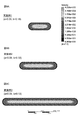
- FIG. 18A is a diagram showing the results of calculating the area ratio of the high shear rate region, FIG. 18A is Example 1, FIG. 18B is Example 2, FIG. 18C is Example 3, FIG. 18D is Comparative Example 1, and FIG. The result of 2.
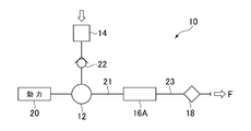
- the dispersion apparatus 10 illustrated in FIG. 1 includes a compressor 12, a processing liquid supply unit 14, a nozzle unit 16A, and a cooling unit 18.
- a processing liquid supply unit 14 is connected to the compressor 12 via a check valve 22.
- the compressor 12 is connected to the power 20, and the discharge port is connected to one side of the compression pipe 21.
- the other side of the compression pipe 21 is connected to the entrance of the nozzle portion 16A.
- the outlet of the nozzle portion 16 ⁇ / b> A is connected to one side of the discharge pipe 23.
- the other side of the discharge pipe 23 is connected to the cooling unit 18.
- the dispersion device 10 is formed so that the treatment liquid supplied from the treatment liquid supply unit 14 can disperse solid matter contained in the treatment liquid by passing through the nozzle portion 16A.
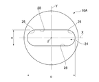
- the nozzle 24 has an oval shape. Accordingly, the nozzle 24 is formed such that the distance D between the first axis X side inner surfaces is longer than the distance H between the second axis Y side inner surfaces.
- the distance D between the first axis X-side inner surfaces 26 can be, for example, 50 to 300 ⁇ m, preferably 50 to 200 ⁇ m.
- the ratio D / H to the distance D between the first axis X-side inner surfaces is 1.5 to 16, preferably 2 to 8, and more preferably 2 to 4 can be used.
- the processing liquid is charged into the processing liquid supply unit 14.
- the treatment liquid includes a dispersion medium and a solid material. From the viewpoint of obtaining a large shear stress, the treatment liquid preferably has a viscosity exceeding 1 (mPa ⁇ s), and more preferably exceeds 100 (mPa ⁇ s).
- the dispersion medium for example, a resin as a coating film formed product and a solvent are included.
- the dispersion medium may be made of polyimide (PI) as a resin and NMP (N-methyl-2-pyrrolidone) as a solvent.
- the dispersion medium may be made of polyvinyl pyrrolidone (PVP) as a resin and water as a solvent.
- the dispersion medium may be made of polyamideimide (PAI) as a resin and NMP as a solvent.
- the solid material a member having an aspect ratio exceeding 10, such as CNT, carbon nanofiber, silver nanowire, inorganic nanotube, cellulose nanofiber, and carbon fiber can be used. Further, it is preferable to use a solid having an aspect ratio exceeding 50. In this case, the solid is, for example, 10 nm in diameter ⁇ 0.5 ⁇ m in length.
- the compressor 12 is driven by the connected power 20 and pushes out the processing liquid supplied from the processing liquid supply unit 14.
- the extruded processing liquid reaches the nozzle portion 16 ⁇ / b> A through the compression pipe 21. Since the flow path of the nozzle 24 is finer than that of the compression pipe 21, the pressure of the processing liquid becomes 10 to 200 MPa immediately before the nozzle 24.
- the treatment liquid becomes a high-speed flow when passing through the nozzle 24.
- the treatment liquid is subjected to a large shear stress.
- the solid contained in the treatment liquid is more finely dispersed by the shear stress. In this way, a dispersion in which the solid matter is more finely dispersed is produced.
- the dispersion immediately after passing through the nozzle 24 is at a high temperature.
- the dispersion apparatus can supply the dispersion liquid to the cooling unit 18 through the discharge pipe 23, cool the dispersion liquid to a predetermined temperature, and then discharge the dispersion liquid.
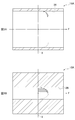
- the nozzle 24 is formed in an oval shape, so that the flow velocity distribution differs between the first axis X and the second axis Y as shown in FIGS. 3A and 3B. That is, on the first axis X, the flow velocity is substantially constant throughout the nozzle 24 (FIG. 3A). Therefore, the treatment liquid has a low shear rate (also referred to as a velocity gradient) in the vicinity of the first axis X. As a result, the treatment liquid receives a small shear stress in a region where the shear rate is low, that is, in the vicinity of a plane parallel to the plane including the first axis X and the traveling direction F. Therefore, the solid matter contained in the treatment liquid smoothly passes through the nozzle 24 without clogging in the vicinity of a plane parallel to the plane including the first axis X and the traveling direction F.
- the flow velocity is faster at the center of the nozzle 24 (FIG. 3B). That is, the treatment liquid has a high shear rate in the vicinity of the second axis Y.
- the treatment liquid and the solid contained in the treatment liquid are subjected to a large shear stress in a region where a high shear rate is generated (high shear rate region), that is, in the vicinity of a plane parallel to the plane including the second axis Y and the traveling direction F. .
- the solid matter is more finely dispersed by this shear stress.
- the solid matter that has reached the inlet of the nozzle 24 is more finely dispersed by receiving a large shear stress in the vicinity of the plane parallel to the plane including the second axis Y and the traveling direction F. . Even if the solid matter is clogged in the flow path of the nozzle 24 by receiving a large shear stress, it can smoothly pass through the nozzle 24 by changing the direction in a direction parallel to the first axis X. .
- the nozzle 24 applies a large shear stress to the treatment liquid in the vicinity of the plane parallel to the plane including the second axis Y and the traveling direction F, and near the plane parallel to the plane including the first axis X and the traveling direction F. Since the shear stress that the treatment liquid receives is small, the treatment liquid is passed smoothly.
- the dispersion device 10 can disperse the solid matter more finely while preventing the solid matter contained in the processing liquid from clogging the flow path as the entire nozzle 24.
- the present invention is not limited to the above-described embodiment, and can be appropriately changed within the scope of the gist of the present invention.
- the present invention is not limited to this, and the horizontally long hexagonal nozzle 30 that is long in the direction parallel to the first axis X (FIG. 4). Or a horizontally long rectangular nozzle 32 (FIG. 5).
- the nozzle portions 16B and 16C shown in FIGS. 4 and 5 have a substantially constant flow rate across the nozzles 30 and 32 on the first axis X, and the center of the nozzles 30 and 32 on the second axis Y is centered. Since it is formed so that the flow velocity becomes faster, the same effect as the above embodiment can be obtained.
- a circular nozzle 34 may be used as shown in FIG.
- the nozzle is formed so that the friction force between the first axis X-side inner surface 36 and the treatment liquid is smaller than that of the second axis Y-side inner surface 38.
- the nozzle 34 may hold the first axis X-side inner surface 36 at a higher temperature than the second axis Y-side inner surface 38.
- the nozzle 34 may be formed such that the first axis X-side inner surface 36 has a smaller roughness than the second axis Y-side inner surface 38.
- the nozzle 34 may form the first axis X-side inner surface 36 so as to have no affinity for the processing liquid.
- the nozzle portion 16D has a substantially constant flow velocity across the nozzle 34 in the first axis X, and the center of the nozzle 34 in the second axis Y is more central. Since it is formed so as to increase the flow velocity, the same effect as in the above embodiment can be obtained.
- ⁇ density (kg / m 3 )
- u average flow velocity (m / s)
- D circular tube diameter (mm)
- ⁇ viscosity (Pa ⁇ s).
- the shear rate ⁇ (r) at the position r in the radial direction can be obtained by the following equation (4).
- ⁇ (r)
- 4 ur / R 2 (4)
- the fluid is an incompressible Newtonian fluid, a solution containing 8.5 wt% of PI (polyimide) with respect to NMP (N-methyl-2-pyrrolidone) (density ⁇ : 1052 kg / m 3 ), viscosity ⁇ : 0.26 Pa ⁇ s ).
- the nozzle shape was a nozzle whose front shape was an oval shape.
- Table 1 shows the dimensions of each part. As a comparative example, calculation was performed for two types of nozzles having a perfect circle shape and different diameters.
- FIGS. 8A to C and FIGS. 9A and 9B show simulation results of the velocity distribution of the nozzles according to the first to third embodiments.
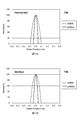
- 9A and 9B the vertical axis indicates the flow rate arrival rate (%) when the maximum flow rate is 100, and the horizontal axis indicates the position in the X-axis or Y-axis direction.
- 10A and 10B and FIGS. 11A and 11B are simulation results of Comparative Examples 1 and 2.
- the nozzles according to Comparative Examples 1 and 2 have the same flow velocity distribution on the X axis and the Y axis.
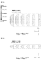
- FIGS. 12A and 12B show velocity vectors of the nozzle according to Example 1 from the nozzle inlet to 0.5 mm.
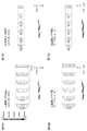
- 13A to 13D are velocity vectors of Comparative Examples 1 and 2.
- FIG. 12A and 12B show velocity vectors of the nozzle according to Example 1 from the nozzle inlet to 0.5 mm.
- 13A to 13D are velocity vectors of Comparative Examples 1 and 2.
- FIGS. 14A to 14C and FIGS. 15A and 15B show the simulation results of the shear rate distribution of the nozzles according to the first to third embodiments.
- 15A and 15B the vertical axis represents the shear rate (1 / s), and the horizontal axis represents the position in the X-axis or Y-axis direction.
- 16A and 16B and FIGS. 17A and 17B are simulation results of Comparative Examples 1 and 2.
- the nozzles according to Comparative Examples 1 and 2 have the same shear rate distribution on the X axis and the Y axis.
- Table 2 shows the result of calculating the area ratio in the high shear rate region.
- 18A to 18E show high shear rate regions when the shear rate is 1 ⁇ 10 7 (1 / s). From this figure, the nozzles according to Examples 1 to 3 have a large area of the high shear rate area (black part in the figure) and a wide area with a low shear rate (white part in the figure). Therefore, it can be said that the solid matter can be dispersed more finely while preventing the solid matter contained in the treatment liquid from clogging the flow path as the whole nozzle.
- Comparative Example 1 since the nozzle inner diameter is large, the area of the high shear rate region is small and occupied by the region where the shear rate is almost small, so it can be said that it is difficult to efficiently disperse the solid matter.
- Comparative Example 2 although the area of the high shear rate region is large, the region where the shear rate is low is narrow, so it can be said that solids are likely to clog the flow path.
- Dispersing devices 16A to 16D Nozzle parts 24, 30, 32, 34 Nozzles 26, 36 First axis X-side inner surface 28, 38 Second axis Y-side inner surface D Distance between first axis X-side inner surface F Traveling direction H Second Distance X between axis Y side inner surface First axis Y Second axis
Landscapes
- Chemical & Material Sciences (AREA)
- Dispersion Chemistry (AREA)
- Chemical Kinetics & Catalysis (AREA)
- Coating Apparatus (AREA)
- Details Or Accessories Of Spraying Plant Or Apparatus (AREA)
- Colloid Chemistry (AREA)
- Physical Or Chemical Processes And Apparatus (AREA)
Abstract
加圧された処理液がノズル(24)を通過することによって、前記処理液に含まれる固形物を分散させる分散装置(10)において、前記ノズル(24)は、前記処理液の進行方向(F)に直交する第1軸(X)において、前記ノズル(24)の全体で流速がほぼ一定であり、前記進行方向(F)及び前記第1軸(X)に直交する第2軸(Y)において、前記ノズル(24)の中央がより流速が速いことを特徴とする、固形物をより細かく分散することができる分散装置及び分散方法を提供する。
Description
本発明は、分散装置及び分散方法に関する。
固形物を細かく分散する装置として、固形物を含有した処理液にせん断応力を与え、当該せん断応力により固形物を細かく分散する分散装置が知られている(例えば、特許文献1)。上記特許文献1の分散装置は、150MPaの圧力を印加した状態でスラリーをノズルに通過させることにより、スラリーにせん断応力を与えて、スラリー中の固形物を細かく分散させる。
上記分散装置は、固形物として例えば、束状のカーボンナノチューブ(以下、「CNT」という)を分散し得る。
ノズルにおいてCNTに大きなせん断応力を与えるには、CNTを含有した粘度の高い処理液を用いることや、小さいノズル径を有するノズルを用いることが有効である。ところが、粘度の高い処理液や、小さいノズル径を有するノズルを用いた場合、CNTがノズルに詰まってしまうという問題があった。
また、ノズル径を段階的に小さくした複数のノズルに、多段的に処理液を通すことにより、CNTを徐々に分散させる方法も考えられる。ところが、多段的に処理液をノズルに通すことにより、CNTの短尺化が進んでしまう、という問題があった。
そこで本発明は、固形物をより細かく分散することができる分散装置及び分散方法を提供することを目的とする。
本発明に係る分散装置は、加圧された処理液がノズルを通過することによって、前記処理液に含まれる固形物を分散させる分散装置において、前記ノズルは、前記処理液の進行方向に直交する第1軸において、前記ノズルの全体で流速がほぼ一定であり、前記進行方向及び前記第1軸に直交する第2軸において、前記ノズルの中央がより流速が速いことを特徴とする。
本発明に係る分散方法は、加圧された処理液がノズルを通過する工程を備え、前記処理液に含まれる固形物を分散させる分散方法において、前記処理液の進行方向に直交する第1軸において前記ノズルの全体で流速がほぼ一定であり、前記進行方向及び前記第1軸に直交する第2軸において前記ノズルの中央がより流速が速いノズルに、前記処理液を通過させることを特徴とする。
本発明によれば、第2軸及び進行方向を含む平面と平行な面近傍において処理液に大きいせん断応力を与えながら、第1軸及び進行方向を含む平面と平行な面近傍においては処理液が受けるせん断応力を小さくすることにより、スムーズに処理液を通過させる。これにより、ノズル全体として、処理液に含まれる固形物が流路に詰まるのを防止しながら、固形物をより細かく分散することができる。
以下、図面を参照して本発明の実施形態について詳細に説明する。
(全体構成)
図1に示す分散装置10は、圧縮機12、処理液供給部14、ノズル部16A、及び冷却部18を備える。圧縮機12には、逆止弁22を介して処理液供給部14が接続されている。圧縮機12は、動力20に接続されており、吐出口が圧縮配管21の一側に接続されている。圧縮配管21の他側は、ノズル部16Aの入り口に接続されている。ノズル部16Aの出口は、排出配管23の一側に接続されている。排出配管23の他側は、冷却部18に接続されている。分散装置10は、処理液供給部14から供給された処理液が、ノズル部16Aを通過することにより、前記処理液に含まれる固形物を分散し得るように形成されている。
図1に示す分散装置10は、圧縮機12、処理液供給部14、ノズル部16A、及び冷却部18を備える。圧縮機12には、逆止弁22を介して処理液供給部14が接続されている。圧縮機12は、動力20に接続されており、吐出口が圧縮配管21の一側に接続されている。圧縮配管21の他側は、ノズル部16Aの入り口に接続されている。ノズル部16Aの出口は、排出配管23の一側に接続されている。排出配管23の他側は、冷却部18に接続されている。分散装置10は、処理液供給部14から供給された処理液が、ノズル部16Aを通過することにより、前記処理液に含まれる固形物を分散し得るように形成されている。
ノズル部16Aは、図2に示すように、円柱状の部材で形成され、処理液が通過するノズル24を有する。ノズル24は、圧縮配管21の内径に比べ、流路が微細に形成されている。ノズル24は、処理液の進行方向Fに平行に開口しており、進行方向Fに直交する第1軸Xと、前記進行方向F及び前記第1軸Xに直交する第2軸Yとにおいて、流速分布が異なるように形成されている。すなわち、ノズル24は、前記第1軸Xにおいて前記ノズル24の全体で流速がほぼ一定であり、前記第2軸Yにおいて前記ノズル24の中央がより流速が速くなるように形成されている。なお説明の便宜上、進行方向Fは、ノズル24の中心を通るものとする。
本実施形態の場合、ノズル24は、長円形状を有する。これによりノズル24は、第1軸X側内面間の距離Dが、第2軸Y側内面間の距離Hより、長く形成されている。第1軸X側内面26間の距離Dは、例えば、50~300μm、好ましくは50~200μmとすることができる。第2軸Y側内面28間の距離をHとすると、第1軸X側内面間の距離Dとの比D/Hは、1.5~16、好ましくは2~8、さらに好ましくは2~4とすることができる。
(動作及び効果)
次に上記のように構成された分散装置10の動作及び効果を説明する。まず、処理液供給部14に処理液を投入する。処理液は、分散媒と、固形物とを含む。処理液は、大きいせん断応力を得る観点から、1(mPa・s)を超える粘度を有するのが好ましく、100(mPa・s)を超えるのがより好ましい。
次に上記のように構成された分散装置10の動作及び効果を説明する。まず、処理液供給部14に処理液を投入する。処理液は、分散媒と、固形物とを含む。処理液は、大きいせん断応力を得る観点から、1(mPa・s)を超える粘度を有するのが好ましく、100(mPa・s)を超えるのがより好ましい。
分散媒としては、例えば塗膜形成物としての樹脂と、溶媒とを含む。例えば、分散媒は、樹脂としてのポリイミド(PI)と、溶媒としてのNMP(N-メチル-2-ピロリドン)とで作製してもよい。また分散媒は、樹脂としてのポリビニルピロリドン(PVP)と、溶媒としての水とで作製してもよい。さらに分散媒は、樹脂としてのポリアミドイミド(PAI)と、溶媒としてのNMPとで作製してもよい。
固形物は、アスペクト比が10を超える部材、例えば、CNTやカーボンナノファイバ、銀ナノワイヤ、無機ナノチューブ、セルロースナノファイバー、炭素繊維等を用いることができる。またアスペクト比が50を超える固形物を用いるのが好ましい。この場合、固形物は、例えば直径10nm×長さ0.5μmである。
圧縮機12は接続された動力20によって駆動し、処理液供給部14から供給された上記処理液を押し出す。押し出された処理液は、圧縮配管21を通じてノズル部16Aへ到達する。ノズル24は、圧縮配管21に比べ流路が微細に形成されていることにより、処理液の圧力は、ノズル24直前で10~200MPaになる。
処理液は、ノズル24を通過する際、高速流となる。ノズル24を通過することにより、処理液は大きいせん断応力を受ける。前記せん断応力によって処理液に含まれる固形物がより細かく分散する。このようにして固形物がより細かく分散した分散液が作製される。ノズル24を通過した直後の分散液は、高温である。分散装置は、排出配管23を通じて冷却部18に分散液を供給し、分散液を所定温度に冷却してから、排出し得る。
本実施形態の場合、ノズル24は長円形状に形成されていることにより、図3A,Bに示すように、第1軸Xと第2軸Yとで流速分布が異なる。すなわち、第1軸Xにおいて、流速は、ノズル24の全体で流速がほぼ一定となる(図3A)。したがって、処理液は、第1軸X近傍においてせん断速度(速度勾配ともいう。)が小さい。これにより処理液は、せん断速度が小さい領域、すなわち第1軸X及び進行方向Fを含む平面と平行な面近傍において、受けるせん断応力が小さい。したがって処理液に含まれる固形物は、第1軸X及び進行方向Fを含む平面と平行な面近傍において、詰まることなくスムーズにノズル24内を通過する。
一方、第2軸Yにおいて、流速は、ノズル24の中央がより速い(図3B)。すなわち処理液は、第2軸Y近傍においてせん断速度が大きい。これにより処理液及び処理液に含まれる固形物は、大きなせん断速度が生じる領域(高せん断速度領域)、すなわち第2軸Y及び進行方向Fを含む平面と平行な面近傍において大きいせん断応力を受ける。このせん断応力によって固形物は、より細かく分散する。
上記のように本実施形態の場合、ノズル24入口に到達した固形物は、第2軸Y及び進行方向Fを含む平面と平行な面近傍において、大きいせん断応力を受けることにより、より細かく分散する。固形物は、大きいせん断応力を受けることによって、仮にノズル24の流路に詰まったとしても、第1軸Xに平行な方向に向きを変えることによって、スムーズにノズル24内を通過することができる。
このようにノズル24は、第2軸Y及び進行方向Fを含む平面と平行な面近傍において処理液に大きいせん断応力を与えながら、第1軸X及び進行方向Fを含む平面と平行な面近傍においては処理液が受けるせん断応力が小さいので、スムーズに処理液を通過させる。
したがって分散装置10は、ノズル24全体として、処理液に含まれる固形物が流路に詰まるのを防止しながら、固形物をより細かく分散させることができる。
(変形例)
本発明は上記実施形態に限定されるものではなく、本発明の趣旨の範囲内で適宜変更することが可能である。
本発明は上記実施形態に限定されるものではなく、本発明の趣旨の範囲内で適宜変更することが可能である。
例えば、上記実施形態の場合、ノズル24は長円形状を有する場合について説明したが、本発明はこれに限らず、第1軸Xに平行な方向に長い横長の六角形状のノズル30(図4)や、横長の四角形状のノズル32(図5)でもよい。上記図4及び図5に示すノズル部16B、16Cは、前記第1軸Xにおいて前記ノズル30、32の全体で流速がほぼ一定であり、前記第2軸Yにおいて前記ノズル30、32の中央がより流速が速くなるように形成されているので、上記実施形態と同様の効果を得ることができる。
また、図6に示すように円形状のノズル34を用いてもよい。この場合、ノズルは、第1軸X側内面36が、第2軸Y側内面38より、処理液との間の摩擦力が小さくなるように形成されている。例えば、ノズル34は、第1軸X側内面36を、第2軸Y側内面38より、高温に保持することとしてもよい。また、ノズル34は、第1軸X側内面36を、第2軸Y側内面38より、粗さが小さくなるように形成してもよい。さらにノズル34は、第1軸X側内面36を、処理液に対し非親和性を有するように形成してもよい。
このように形成されたノズル34を備えることにより、ノズル部16Dは、前記第1軸Xにおいて前記ノズル34の全体で流速がほぼ一定であり、前記第2軸Yにおいて前記ノズル34の中央がより流速が速くなるように形成されるので、上記実施形態と同様の効果を得ることができる。
(シミュレーション)
ノズル内の流体の流れをシミュレーションにより求めた。レイノルズ数(Re)は、下記式(1)で求めることができる。
Re=(ρ・u・D)/μ・・・(1)
ノズル内の流体の流れをシミュレーションにより求めた。レイノルズ数(Re)は、下記式(1)で求めることができる。
Re=(ρ・u・D)/μ・・・(1)
但し、ρ:密度(kg/m3)、u:平均流速(m/s)、D:円管直径(mm)、μ:粘度(Pa・s)である。Re<2000のとき、流体の流れは層流とみなすことができる。
ここで平均流速uは、m:重量流量(kg/s)、A:断面積(m2)とすると、下記式(2)で求めることができる。
u=m/(ρA)・・・(2)
u=m/(ρA)・・・(2)
半径Rの円管に流れる流体の半径方向の位置rにおける流速u(r)は、下記式(3)で求めることができる。
u(r)=2u{1-(r/R)2}・・・(3)
u(r)=2u{1-(r/R)2}・・・(3)
半径方向の位置rにおけるせん断速度γ(r)は、下記式(4)で求めることができる。
γ(r)=|du/dr|=4ur/R2・・・(4)
γ(r)=|du/dr|=4ur/R2・・・(4)
また、せん断応力τは、τ=μ・(du/dr)=μγ(r)の関係にある。
(モデル)
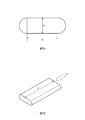
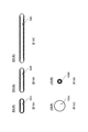
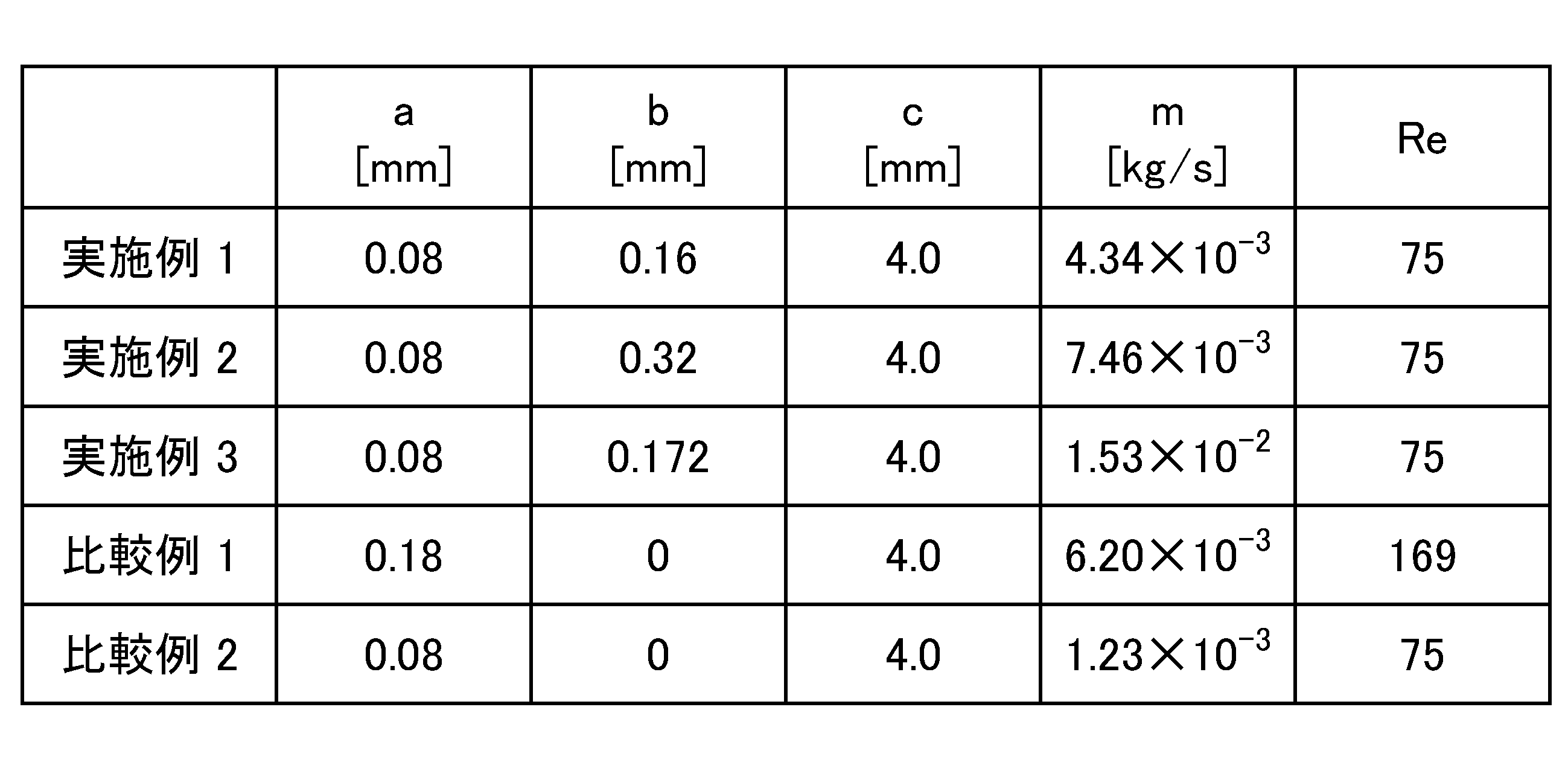
流体は、非圧縮ニュートン流体とし、NMP(N‐メチル‐2‐ピロリドン)に対しPI(ポリイミド)を8.5wt%含む溶液(密度ρ:1052kg/m3)、粘度μ:0.26Pa・s)を想定して計算した。ノズル形状は、図7A,Bに示すように、正面形状が長円形状であるノズルとした。各部の寸法を表1に示す。比較例として、真円形状であって直径が異なる2種のノズルについて計算した。
流体は、非圧縮ニュートン流体とし、NMP(N‐メチル‐2‐ピロリドン)に対しPI(ポリイミド)を8.5wt%含む溶液(密度ρ:1052kg/m3)、粘度μ:0.26Pa・s)を想定して計算した。ノズル形状は、図7A,Bに示すように、正面形状が長円形状であるノズルとした。各部の寸法を表1に示す。比較例として、真円形状であって直径が異なる2種のノズルについて計算した。
(計算結果)
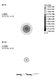
図8A~C及び図9A,Bに実施例1~3に係るノズルの速度分布のシミュレーション結果を示す。図9A,Bは、縦軸が最大の流速を100とした場合の流速到達率(%)、横軸がX軸又はY軸方向の位置を示す。図10A,B及び図11A,Bは比較例1及び2のシミュレーション結果である。本図から、実施例1~3に係るノズルは、X軸とY軸において流速分布が異なり、X軸において速度が一定の領域があることが確認された。一方、比較例1及び2に係るノズルは、X軸とY軸において、流速分布が同じである。
図8A~C及び図9A,Bに実施例1~3に係るノズルの速度分布のシミュレーション結果を示す。図9A,Bは、縦軸が最大の流速を100とした場合の流速到達率(%)、横軸がX軸又はY軸方向の位置を示す。図10A,B及び図11A,Bは比較例1及び2のシミュレーション結果である。本図から、実施例1~3に係るノズルは、X軸とY軸において流速分布が異なり、X軸において速度が一定の領域があることが確認された。一方、比較例1及び2に係るノズルは、X軸とY軸において、流速分布が同じである。
図12A,Bに実施例1に係るノズルの、ノズル入口から0.5mmまでの速度ベクトルを示す。図13A~Dは、比較例1及び2の速度ベクトルである。
図14A~C及び図15A,Bに実施例1~3に係るノズルのせん断速度分布のシミュレーション結果を示す。図15A,Bは、縦軸がせん断速度(1/s)、横軸がX軸又はY軸方向の位置を示す。図16A,B及び図17A,Bは比較例1及び2のシミュレーション結果である。本図から、実施例1~3に係るノズルは、X軸とY軸においてせん断速度の分布状態が異なり、X軸においてせん断速度が一定の領域があることが確認された。一方、比較例1及び2に係るノズルは、X軸とY軸において、せん断速度の分布が同じである。
高せん断速度領域の面積率を計算した結果を表2に示す。またせん断速度が1×10⁷(1/s)のときの高せん断速度領域を図18A~Eに示す。本図から、実施例1~3に係るノズルは、高せん断速度領域(本図中黒色部分)の面積が広く、さらにせん断速度が小さい領域(本図中白色部分)も広く形成されていることから、ノズル全体として、処理液に含まれる固形物が流路に詰まるのを防止しながら、固形物をより細かく分散することができるといえる。
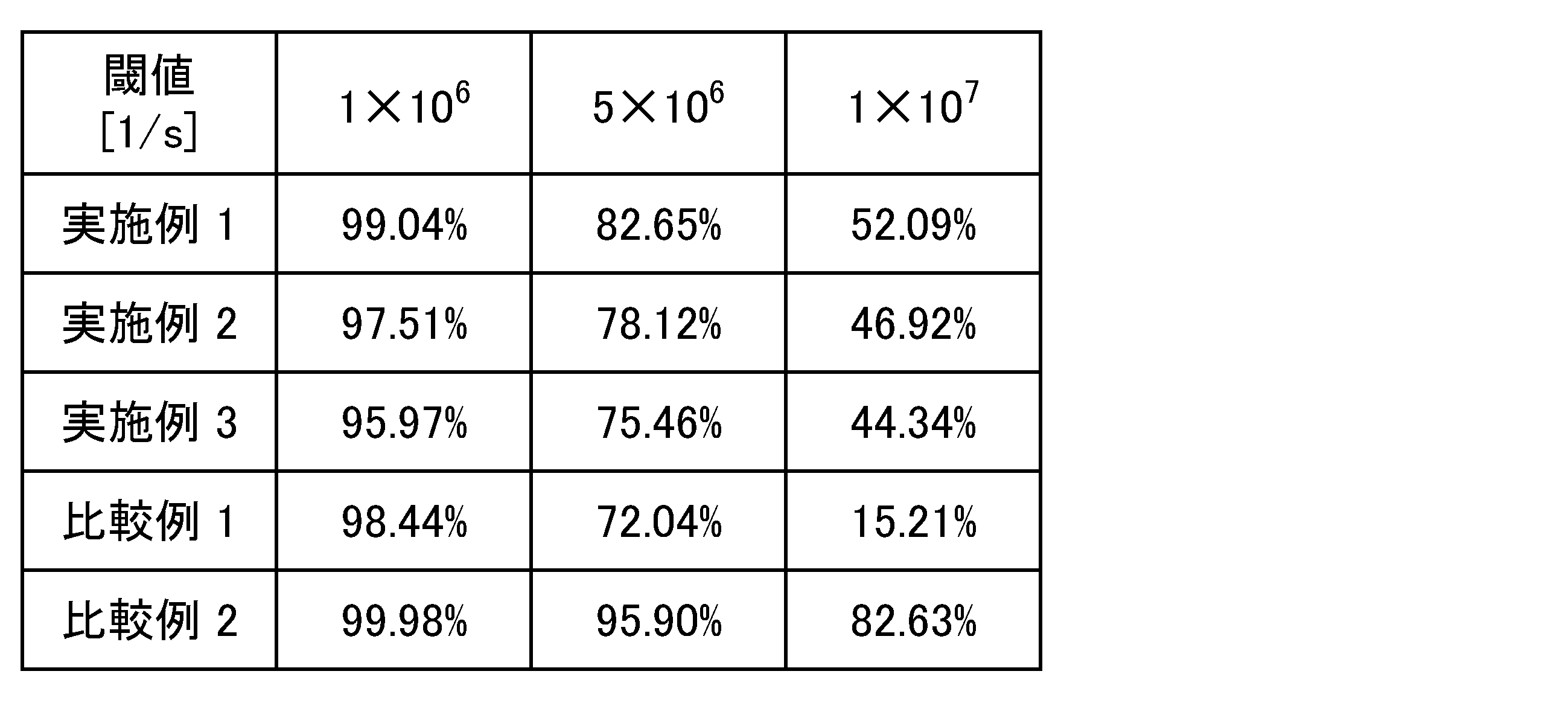
一方、比較例1は、ノズル内径が大きいことから、高せん断速度領域の面積が狭くほぼせん断速度が小さい領域で占められているので、固形物を効率的に分散させるのが困難といえる。また比較例2は、高せん断速度領域の面積は広いものの、せん断速度が小さい領域が狭いので、固形物が流路に詰まりやすいといえる。
10 分散装置
16A~16D ノズル部
24,30,32,34 ノズル
26,36 第1軸X側内面
28,38 第2軸Y側内面
D 第1軸X側内面間の距離
F 進行方向
H 第2軸Y側内面間の距離
X 第1軸
Y 第2軸
16A~16D ノズル部
24,30,32,34 ノズル
26,36 第1軸X側内面
28,38 第2軸Y側内面
D 第1軸X側内面間の距離
F 進行方向
H 第2軸Y側内面間の距離
X 第1軸
Y 第2軸
Claims (6)
- 加圧された処理液がノズルを通過することによって、前記処理液に含まれる固形物を分散させる分散装置において、
前記ノズルは、
前記処理液の進行方向に直交する第1軸において、前記ノズルの全体で流速がほぼ一定であり、
前記進行方向及び前記第1軸に直交する第2軸において、前記ノズルの中央がより流速が速い
ことを特徴とする分散装置。 - 前記ノズルは、前記第1軸側内面間の距離が、前記第2軸側内面間の距離より、長く形成されていることを特徴とする請求項1記載の分散装置。
- 前記ノズルは、前記第1軸側内面が、前記第2軸側内面より、高温に保持されていることを特徴とする請求項1記載の分散装置。
- 前記ノズルは、前記第1軸側内面が、前記第2軸側内面より、粗さが小さいことを特徴とする請求項1記載の分散装置。
- 前記ノズルは、前記第1軸側内面が、前記処理液に対し非親和性を有することを特徴とする請求項1記載の分散装置。
- 加圧された処理液がノズルを通過する工程を備え、前記処理液に含まれる固形物を分散させる分散方法において、
前記処理液の進行方向に直交する第1軸において、前記ノズルの全体で流速がほぼ一定であり、前記進行方向及び前記第1軸に直交する第2軸において前記ノズルの中央がより流速が速いノズルに、前記処理液を通過させることを特徴とする分散方法。
Applications Claiming Priority (2)
| Application Number | Priority Date | Filing Date | Title |
|---|---|---|---|
| JP2014236361A JP6494983B2 (ja) | 2014-11-21 | 2014-11-21 | 分散装置及び分散方法 |
| JP2014-236361 | 2014-11-21 |
Publications (1)
| Publication Number | Publication Date |
|---|---|
| WO2016080339A1 true WO2016080339A1 (ja) | 2016-05-26 |
Family
ID=56013876
Family Applications (1)
| Application Number | Title | Priority Date | Filing Date |
|---|---|---|---|
| PCT/JP2015/082091 Ceased WO2016080339A1 (ja) | 2014-11-21 | 2015-11-16 | 分散装置及び分散方法 |
Country Status (3)
| Country | Link |
|---|---|
| JP (1) | JP6494983B2 (ja) |
| TW (1) | TWI693098B (ja) |
| WO (1) | WO2016080339A1 (ja) |
Citations (6)
| Publication number | Priority date | Publication date | Assignee | Title |
|---|---|---|---|---|
| JPS5895222U (ja) * | 1981-12-21 | 1983-06-28 | 三菱重工業株式会社 | ジエツトミキサ |
| JPH0194933A (ja) * | 1987-10-02 | 1989-04-13 | Sayama Trading:Kk | 乳化装置 |
| JPH08117585A (ja) * | 1994-10-19 | 1996-05-14 | Aqua Tec:Kk | 微粒化装置 |
| JP2007224997A (ja) * | 2006-02-22 | 2007-09-06 | Fuji Xerox Co Ltd | 逆止弁およびこれを用いた液製造装置 |
| JP2010042956A (ja) * | 2008-08-12 | 2010-02-25 | Univ Of Tsukuba | 水系媒体中へのカーボンナノチューブの分散方法 |
| JP2012192354A (ja) * | 2011-03-17 | 2012-10-11 | Biryu:Kk | 乳化分散液製造システム |
Family Cites Families (3)
| Publication number | Priority date | Publication date | Assignee | Title |
|---|---|---|---|---|
| EP0712655B1 (en) * | 1994-06-13 | 2002-03-27 | Chiyoda Corporation | Gas-liquid contact gas dispersion pipe and apparatus using the same |
| EP1757370B8 (en) * | 2005-08-24 | 2012-03-14 | Brother Kogyo Kabushiki Kaisha | Film forming apparatus and jetting nozzle |
| JP5293989B2 (ja) * | 2007-07-24 | 2013-09-18 | ノードソン株式会社 | 少量液体の噴霧装置 |
-
2014
- 2014-11-21 JP JP2014236361A patent/JP6494983B2/ja active Active
-
2015
- 2015-11-16 WO PCT/JP2015/082091 patent/WO2016080339A1/ja not_active Ceased
- 2015-11-20 TW TW104138426A patent/TWI693098B/zh active
Patent Citations (6)
| Publication number | Priority date | Publication date | Assignee | Title |
|---|---|---|---|---|
| JPS5895222U (ja) * | 1981-12-21 | 1983-06-28 | 三菱重工業株式会社 | ジエツトミキサ |
| JPH0194933A (ja) * | 1987-10-02 | 1989-04-13 | Sayama Trading:Kk | 乳化装置 |
| JPH08117585A (ja) * | 1994-10-19 | 1996-05-14 | Aqua Tec:Kk | 微粒化装置 |
| JP2007224997A (ja) * | 2006-02-22 | 2007-09-06 | Fuji Xerox Co Ltd | 逆止弁およびこれを用いた液製造装置 |
| JP2010042956A (ja) * | 2008-08-12 | 2010-02-25 | Univ Of Tsukuba | 水系媒体中へのカーボンナノチューブの分散方法 |
| JP2012192354A (ja) * | 2011-03-17 | 2012-10-11 | Biryu:Kk | 乳化分散液製造システム |
Also Published As
| Publication number | Publication date |
|---|---|
| TW201637710A (zh) | 2016-11-01 |
| JP6494983B2 (ja) | 2019-04-03 |
| JP2016097354A (ja) | 2016-05-30 |
| TWI693098B (zh) | 2020-05-11 |
Similar Documents
| Publication | Publication Date | Title |
|---|---|---|
| Goh et al. | Directional alignment of carbon nanotubes in polymer matrices: Contemporary approaches and future advances | |
| Vega et al. | Global and local instability of flow focusing: The influence of the geometry | |
| Edmond et al. | Stable jets of viscoelastic fluids and self-assembled cylindrical capsules by hydrodynamic focusing | |
| JP6494983B2 (ja) | 分散装置及び分散方法 | |
| JP2020028848A (ja) | 乳化分散液 | |
| Pathak et al. | Phenomenology and control of buckling dynamics in multicomponent colloidal droplets | |
| Sastry et al. | Numerical simulation of unsteady ethylene glycol/CNTs micropolar nanofluid flow through a squeezing channel: an approach to industrial applications | |
| Ramos-Escobar et al. | Dynamics of formation of poly (vinyl alcohol) filaments with an energetically efficient micro-mixing mechanism | |
| US20070205307A1 (en) | Device and method for creating hydrodynamic cavitation in fluids | |
| Feng et al. | Working mechanism and behavior of Collison nebulizer | |
| KR100991608B1 (ko) | 넓은 입자 직경 범위에서 집속이 가능한 공기 역학 렌즈 | |
| JP2005538839A (ja) | 環状流路を備えた流体処理装置 | |
| Karimzadehkhouei et al. | Increasing the stability of nanofluids with cavitating flows in micro orifices | |
| WO2026016615A1 (zh) | 碳纳米管的分散喷嘴、设备及方法 | |
| US10106419B2 (en) | Method of making graphene nanocomposites by multiphase fluid dynamic dispersion | |
| Tian et al. | Enhanced nanoflow behaviors of polymer melts using dispersed nanoparticles and ultrasonic vibration | |
| US20190022689A1 (en) | Perforated plate with a reduced diameter in one or both edge regions of a row of nozzles | |
| JP2016073939A (ja) | 微細気泡発生装置 | |
| JP2017205739A (ja) | 分散装置用ノズル、そのノズルを備えた分散装置、及び分散方法 | |
| US11338246B2 (en) | Nozzle filter | |
| JP6777359B2 (ja) | 分散装置用ノズル、そのノズルを備えた分散装置、及び分散方法 | |
| Park et al. | Hydrodynamics of CNT dispersion in high shear dispersion mixers | |
| JP6755487B2 (ja) | 微粒化ユニット、微粒化装置及び微粒化方法 | |
| JP2020015632A (ja) | グラフェン分散液の製造方法及び微粒化装置 | |
| CN104646439A (zh) | 带阻尼的中厚板喷淋装置 |
Legal Events
| Date | Code | Title | Description |
|---|---|---|---|
| 121 | Ep: the epo has been informed by wipo that ep was designated in this application |
Ref document number: 15862106 Country of ref document: EP Kind code of ref document: A1 |
|
| NENP | Non-entry into the national phase |
Ref country code: DE |
|
| 122 | Ep: pct application non-entry in european phase |
Ref document number: 15862106 Country of ref document: EP Kind code of ref document: A1 |