WO2016076060A1 - 移載装置及び移載方法 - Google Patents
移載装置及び移載方法 Download PDFInfo
- Publication number
- WO2016076060A1 WO2016076060A1 PCT/JP2015/079125 JP2015079125W WO2016076060A1 WO 2016076060 A1 WO2016076060 A1 WO 2016076060A1 JP 2015079125 W JP2015079125 W JP 2015079125W WO 2016076060 A1 WO2016076060 A1 WO 2016076060A1
- Authority
- WO
- WIPO (PCT)
- Prior art keywords
- slider
- sliders
- rack
- stage
- pinion
- Prior art date
- Legal status (The legal status is an assumption and is not a legal conclusion. Google has not performed a legal analysis and makes no representation as to the accuracy of the status listed.)
- Ceased
Links
Images

Classifications
-
- B—PERFORMING OPERATIONS; TRANSPORTING
- B65—CONVEYING; PACKING; STORING; HANDLING THIN OR FILAMENTARY MATERIAL
- B65G—TRANSPORT OR STORAGE DEVICES, e.g. CONVEYORS FOR LOADING OR TIPPING, SHOP CONVEYOR SYSTEMS OR PNEUMATIC TUBE CONVEYORS
- B65G1/00—Storing articles, individually or in orderly arrangement, in warehouses or magazines
- B65G1/02—Storage devices
- B65G1/04—Storage devices mechanical
Definitions
- This invention relates to a transfer device such as a slide fork.
- a transfer device such as a slide fork
- a three-stage slider of a base part, a middle part, and a top part is connected by a guide block and a guide rail. If these sliders are level in the thickness direction, the connection between the guide block and the guide rail will provide sufficient rigidity against bending due to the weight of the load, but it will be twisted with the forward / backward direction as the central axis. Lack of rigidity.
- sliders are arranged in parallel at the same height to be reinforced (for example, Patent Document 1, JP2014-51345).
- the thickness of the transfer device increases. Therefore, there is a need for a structure in which the twist about the central axis in the advancing / retreating direction of the slider is reduced without increasing the thickness of the transfer device.
- An object of the present invention is to reduce the twist about the central axis in the advancing / retreating direction of the slider without substantially increasing the thickness of the transfer device.
- the present invention is a transfer device for advancing and retreating at least three stages of sliders along the advancing and retreating direction, which are connected to each other by a connecting portion composed of a guide block and a guide rail,
- Each slider has a cross section perpendicular to the advancing and retreating direction, and the height is larger than the horizontal width, and two sliders are arranged one above the other along the height direction.
- a plate extending in the vertical direction is provided on one of the two-stage sliders, and the plate is configured to slide with respect to the other of the two-stage sliders.
- the thickness of the transfer device can be reduced. Since a plate extending in the vertical direction from at least one of the two-stage sliders is provided and slid with respect to the other of the at least two-stage sliders, the thickness direction of the transfer device (in the horizontal plane in the forward / backward direction of the transfer device) The rigidity in the direction perpendicular to the surface is increased, and the torsion about the forward / backward direction of the slider can be reduced.
- a one-stage slider is disposed so as to be connected to both of the two-stage sliders and a connecting portion including a guide block and a guide rail, and one of the two-stage sliders has the one-stage slider.
- the plate extends in the vertical direction from the opposite side of the connecting portion with the slider, and slides with respect to the other of the two-stage sliders on the opposite side of the connecting portion with the first-stage slider.
- the other two-stage slider is connected to at least one stage slider, and the other two-stage slider slides through the plate, so that the structure is small in thickness and high in rigidity. . *
- a fixed slider a second slider that advances and retreats with respect to the fixed slider, a third slider that advances and retreats with respect to the second slider, and a fourth slider that advances and retreats with respect to the third slider.
- a third slider and a fifth slider are arranged to be vertically stacked along the height direction to form the two-stage slider, and the plate is provided on the fifth slider or the third slider, The plate slides against a third slider or a fifth slider;
- a second slider and a fourth slider are arranged to be stacked vertically along the height direction, the fourth slider becomes the first stage slider, and the fourth slider slides against the fixed slider. Is configured to do.
- the fixed slider includes a motor, a first pinion, and a first rack, and the first pinion is driven by the motor
- the second slider includes a second rack that meshes with the first pinion, a second pinion that meshes with the first rack, and a third rack, and is composed of a guide block and a guide rail. It is connected to the fixed slider by the connection part,
- the third slider includes a fourth rack that meshes with the second pinion, a third pinion that meshes with the third rack, and a fifth rack.
- the third slider includes a guide block and a guide rail.
- the fourth slider includes a sixth rack that meshes with the third pinion, a fourth pinion, and is connected to the third slider by a third connection portion that includes a guide block and a guide rail.
- the fifth slider includes a seventh rack that meshes with the fourth pinion, and is connected to the fourth slider by a fourth connection portion including a guide block and a guide rail.
- the second to fifth sliders can be advanced and retracted by rotating the first pinion of the fixed slider.
- the fixed slider comprises a first pinion and a first rack at the top
- the second slider includes a second rack at the upper end in the height direction, a second pinion in the middle, and a third rack at the lower end
- the third slider includes a fourth rack at the upper end in the height direction, a third pinion in the middle, and a fifth rack at the lower end.
- the fourth slider includes a sixth rack at the upper end in the height direction and a fourth pinion below the sixth rack.
- the second connecting portion is lower in height than the first connecting portion
- the third connecting portion is lower in height than the second connecting portion
- the fourth connecting portion is lower than the third connecting portion. Even the height position is lowered.
- the second slider to the fifth slider can be supported by the fixed slider so that the height position becomes lower in order from the second slider to the fifth slider.
- the plate is provided to extend upward on the fifth slider
- One of the third slider or the plate is provided with a first slide shoe made of synthetic resin extending along the advancing and retracting direction, A first slide shoe configured to slide relative to the other of the plate and the third slider;
- One of the fourth slider and the fixed slider is provided with a second slide shoe made of synthetic resin extending along the advancing / retreating direction, The second slide shoe is configured to slide relative to the other of the fourth slider and the fixed slider.
- a pair of the fixed slider and the second to fifth sliders are provided so as to face each other along a direction perpendicular to the advancing and retreating direction in a horizontal plane, and each fifth slider is advancing and retreating.
- the transfer method of the present invention further includes at least three stages of sliders that are connected to each other by a connection portion including a guide block and a guide rail.
- Each slider has a cross section perpendicular to the advancing and retreating direction, and the height is larger than the horizontal width, and two sliders are arranged one above the other along the height direction.
- a plate extending in the vertical direction is provided on one of the two-stage sliders, and the plate uses a transfer device configured to slide with respect to the other of the two-stage sliders, By moving the two-stage slider forward and backward along the forward / backward direction, the article is transferred, and by sliding the plate with respect to the other of the two-stage sliders, the forward / backward direction is the axis. Limit the twist of the slider in the step.
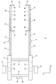
- the slide fork 2 includes a right unit 4 and a left unit 6 and is connected by a connecting portion 21.
- the right unit 4 and the left unit 6 have a bilaterally symmetric structure, and the following description will be focused on the right unit 4.
- 8, 10, 12, 14, and 16 are five-stage sliders, of which the slider 8 is a fixed slider, and the sliders 10 to 16 are sliders that move back and forth in the x direction (forward and backward direction) in FIG.
- the y direction in FIG. 1 is referred to as the left-right direction, and the y direction is also the width direction.
- the five-stage sliders 8 to 16 are used, but a three-stage slider, a seven-stage slider, or the like may be used, and the number of slider stages is arbitrary.
- the base portion 18 is composed of the fixed sliders 8 and 8, the connecting portions 21 and 21, and the top portion 20 is composed of the sliders 16 and 16 at the tip.
- the sliders 16 and 16 are provided with hooks 24 and 24 that can be freely opened and closed at both front and rear ends, and a load (not shown) is pushed and pulled to be transferred.
- a hook motor 26 opens and closes the hook 24, and 28 is a secondary battery such as a lithium ion battery.
- Reference numeral 30 denotes a power supply circuit, which includes a charge / discharge control circuit for the secondary battery 28, a DC / DC converter, and the like.
- Reference numeral 32 denotes a wireless communication unit.
- the slider 16 may include a sensor for detecting a load on the shelf, a sensor for detecting a load on the top portion 20, a station, a load port, a hand for operating the shelf, and the like.
- the hook 24 and the hook motor 26 to the wireless communication unit 32 may not be provided.
- the sliders 8 and 8 are connected by the connecting portion 21, the movable sliders 10 to 16 are moved forward and backward by the pair of slide motors 22 and 22, and the secondary battery 28 is charged by the charger 34.
- the wireless communication unit 36 communicates with the wireless communication unit 32 and gives a command from the controller 38 to the hook motors 26 and 26.
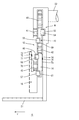
- FIGS. 2 and 3 show the structure of the right unit 4 of the slide fork 2, and the left unit 6 is symmetrical to this.
- Reference numerals 40 to 43 denote pinions, 45 to 51 denote racks, and 54 to 57 denote guide blocks, which are guided by guide rails 58 to 61.
- the slider 10 is moved forward and backward by moving the slider 10 forward and backward by the pinion 40 and the rack 45, and driving the rack 47 by rotating the pinion 41 by the rack 46.
- the slider 14 is moved forward and backward
- by rotating the pinion 43 by the rack 50 and driving the rack 51 the slider 16 is moved forward and backward.
- the forward / backward moving mechanism of the five-stage sliders 8 to 16 is optional, and a chain, a belt, or the like may be used, and the number of slider stages is also arbitrary.
- the surface connected to the other sliders by the guide blocks 55 to 57 is called the front surface, and the opposite surface is called the back surface.
- a plate 70 extending upward is provided on the back side of the slider 16 at the tip. In FIG. 1, the plate 70 is omitted. The plate 70 may be provided on the back side of the slider 12 so as to extend downward.
- a belt-like slide shoe 75 made of synthetic resin is attached to the support surface 72 on the back side of the slider 12, and is brought into contact with the support surface 71 to slide.
- a belt-like slide shoe 76 made of a synthetic resin is attached to the support surface 73 on the back side of the slider 14, and the slide shoe 76 is brought into contact with the support surface 74 of the slider 8 to slide.
- the support surface 71 is supported by the support surface 72 via the slide shoe 75, and the support surface 73 is supported by the support surface 74 via the slide shoe 76, whereby the slider 10 and the slider 14 are stacked one on top of the other. Even if 16 is stacked vertically, the twist of the slider 16 can be reduced.
- the slide shoes 75 and 76 may not be provided, and the support surface 71 may be brought into direct contact with the support surface 72, and the support surface 73 may be brought into direct contact with the support surface 74 so that they slide with respect to each other.
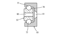
- FIG. 4 shows the structure of the guide block 57 and the guide rail 61, and the other guide blocks and the other guide rails have the same structure.
- Reference numeral 77 is a rolling element such as a ball or a roller
- 78 is a retainer for holding the rolling element 77
- 80 is a screw hole for attachment
- 81 is a screw hole for attachment.
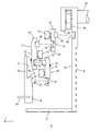
- FIG. 5 shows the relationship between the sliders 12 to 16, and the rack and pinion are omitted.
- the guide blocks 56 and 57 are provided, for example, over the entire length of the sliders 14 and 16, and the guide rails 60 and 61 are provided over the entire length of the sliders 12 and 16, respectively.
- the sliders 12 and 16 are supported by the slider 14, and the sliders 12 and 16 are supported with each other via the slide shoe 75, thereby increasing the rigidity in the y direction (left and right direction). Further, as shown in FIG. 2, the support surface 73 of the slider 14 is supported by the support surface 74 of the slider 8 via the slide shoe 76, thereby increasing the rigidity of the slider 14 in the y direction.
- the slide fork 2 is mounted on a lifting platform of a stacker crane, and is transported to the front of the shelf of the shelf.
- the top portion is stroked up to about twice the length of the sliders 10 to 16.
- Move 20 forward and backward For this reason, for example, luggage can be arranged on the shelf in two rows on the front side and the back side, and the luggage accommodation efficiency is increased.
- the thickness of the units 4 and 6 along the y direction becomes a problem.
- the slider 10 and the slider 14 are stacked vertically, the slider 12 and the slider 16 are stacked vertically, The sliders 12 and 16 are arranged on the left and right with respect to the sliders 10 and 14.
- the thickness of the units 4 and 6 is equal to that of the three-stage slider.
- a plate 70 is provided to support the slider 16 by bringing the support surfaces 71 and 72 into contact with each other via the slide shoe 75; By supporting the slider 14 by bringing the support surfaces 73 and 74 into contact with each other via the slide shoe 76, the twist is limited to a range where there is no problem.
- slide shoes 75 and 76 are used in the embodiment, these may be omitted, and the shape and structure of the slide shoes 75 and 76 are arbitrary. Further, the slide shoe 75 may be attached to the support surface 71, and the slide shoe 76 may be attached to the support surface 74.
Landscapes
- Engineering & Computer Science (AREA)
- Mechanical Engineering (AREA)
- Warehouses Or Storage Devices (AREA)
Abstract
移載装置(2)の厚さを実質的に増さずに、スライダの進退方向を中心軸とする捻れを小さくするために、移載装置(2)は、ガイドブロック(54-57)とガイドレール(58-61)とからなる接続部により互いに接続され、少なくとも3段のスライダを進退させる。各スライダ(8-16)は、進退方向に直角な断面で高さが水平方向の幅よりも大きく、かつ、少なくとも2段のスライダが上下に重ねて配置され、さらに、少なくとも2段のスライダの一方から上下方向に延びるプレート(70)が、少なくとも2段のスライダの他方と摺動するように設けられている。
Description
この発明はスライドフォーク等の移載装置に関する。
スライドフォーク等の移載装置では、例えばベース部、ミドル部、トップ部の3段のスライダを、ガイドブロックとガイドレールとにより接続する。これらのスライダを、厚さ方向を水平にすると、ガイドブロックとガイドレールとによる接続で、荷物の重さによる撓みに対しては十分な剛性が得られるが、進退方向を中心軸とする捻れへの剛性が不足する。そこでスライダを同じ高さで並行に配置して補強することが行われている(例えば特許文献1 JP2014-51345)。
スライダを同じ高さで並行に配置すると、移載装置の厚さ(水平方向の幅)が増す。そこで移載装置の厚さを増さずに、スライダの進退方向を中心軸とする捻れを小さくする構造が必要である。
この発明の課題は、移載装置の厚さを実質的に増さずに、スライダの進退方向を中心軸とする捻れを小さくすることにある。
この発明は、ガイドブロックとガイドレールとから成る接続部により互いに接続されている、少なくとも3段のスライダを進退方向に沿って進退させる移載装置であって、
各スライダは進退方向に直角な断面で高さが水平方向の幅よりも大きく、かつ2段のスライダが高さ方向に沿って上下に重ねて配置され、
さらに、前記2段のスライダの一方に上下方向に延びるプレートが設けられ、前記プレートは前記2段のスライダの他方に対して摺動するように構成されていることを特徴とする。
各スライダは進退方向に直角な断面で高さが水平方向の幅よりも大きく、かつ2段のスライダが高さ方向に沿って上下に重ねて配置され、
さらに、前記2段のスライダの一方に上下方向に延びるプレートが設けられ、前記プレートは前記2段のスライダの他方に対して摺動するように構成されていることを特徴とする。
この発明では、スライダを上下に重ねて配置するので、移載装置の厚さを小さくできる。そして少なくとも2段のスライダの一方から上下方向に延びるプレートを設け、少なくとも2段のスライダの他方に対して摺動させるので、移載装置の厚さ方向(移載装置の進退方向に水平面内で直角な方向)の剛性が増し、スライダの進退方向を中心とする捻れを小さくできる。
好ましくは、前記2段のスライダの双方と、ガイドブロックとガイドレールとから成る接続部により接続されるように、1段のスライダが配置され、前記2段のスライダの一方での、前記1段のスライダとの接続部の反対側から、前記プレートが上下方向に延びて、前記1段のスライダとの接続部の反対側で、前記2段のスライダの他方に対して摺動するように構成されている。このようにすると、少なくとも1段のスライダに、他の2段のスライダが接続され、他の2段のスライダがプレートを介して摺動するので、厚さが小さく、しかも剛性が高い構造となる。
特に好ましくは、固定のスライダと、固定のスライダに対して進退する第2のスライダと、第2のスライダに対して進退する第3のスライダと、第3のスライダに対して進退する第4のスライダと、第4のスライダに対して進退する第5のスライダから成る、少なくとも5段のスライダが設けられ、
第3のスライダと第5のスライダとが高さ方向に沿って上下に重ねて配置されて、前記2段のスライダとなり、かつ第5のスライダまたは第3のスライダに前記プレートが設けられて、前記プレートが第3のスライダまたは第5のスライダに対して摺動し、
第2のスライダと第4のスライダとが高さ方向に沿って上下に重ねて配置され、第4のスライダが前記1段のスライダとなり、さらに第4のスライダが固定のスライダに対して摺動するように構成されている。
第3のスライダと第5のスライダとが高さ方向に沿って上下に重ねて配置されて、前記2段のスライダとなり、かつ第5のスライダまたは第3のスライダに前記プレートが設けられて、前記プレートが第3のスライダまたは第5のスライダに対して摺動し、
第2のスライダと第4のスライダとが高さ方向に沿って上下に重ねて配置され、第4のスライダが前記1段のスライダとなり、さらに第4のスライダが固定のスライダに対して摺動するように構成されている。
このようにすると合計5段のスライダを、3段のスライダ分の厚さで配置できる。従ってストロークが長く、厚さ(水平方向の幅)が小さく、進退方向を中心軸とする捻れも小さい移載装置が得られる。
好ましくは、固定のスライダはモータと第1のピニオンと第1のラックとを備え、第1のピニオンは前記モータにより駆動され、
第2のスライダは、第1のピニオンと噛み合う第2のラックと、第1のラックと噛み合う第2のピニオンと、第3のラックとを備え、かつガイドブロックとガイドレールとから成る第1の接続部により固定のスライダと接続され、
第3のスライダは、第2のピニオンと噛み合う第4のラックと、第3のラックと噛み合う第3のピニオンと、第5のラックとを備え、かつガイドブロックとガイドレールとから成る第2の接続部により第2のスライダと接続され、
第4のスライダは、第3のピニオンと噛み合う第6のラックと、第4のピニオンとを備え、かつガイドブロックとガイドレールとから成る第3の接続部により第3のスライダと接続され、
第5のスライダは第4のピニオンと噛み合う第7のラックを備え、かつガイドブロックとガイドレールとから成る第4の接続部により第4のスライダと接続されている。
第2のスライダは、第1のピニオンと噛み合う第2のラックと、第1のラックと噛み合う第2のピニオンと、第3のラックとを備え、かつガイドブロックとガイドレールとから成る第1の接続部により固定のスライダと接続され、
第3のスライダは、第2のピニオンと噛み合う第4のラックと、第3のラックと噛み合う第3のピニオンと、第5のラックとを備え、かつガイドブロックとガイドレールとから成る第2の接続部により第2のスライダと接続され、
第4のスライダは、第3のピニオンと噛み合う第6のラックと、第4のピニオンとを備え、かつガイドブロックとガイドレールとから成る第3の接続部により第3のスライダと接続され、
第5のスライダは第4のピニオンと噛み合う第7のラックを備え、かつガイドブロックとガイドレールとから成る第4の接続部により第4のスライダと接続されている。
このようにすると、固定のスライダの第1のピニオンを回転させることにより、第2のスライダ~第5のスライダを進退させることができる。
好ましくは、固定のスライダは、上部に第1のピニオンと第1のラックとを備え、
第2のスライダは、高さ方向の上端に第2のラックを、中間に第2のピニオンを、下端に第3のラックを備え、
第3のスライダは、高さ方向の上端に第4のラックを、中間に第3のピニオンを、下端に第5のラックを備え、
第4のスライダは、高さ方向の上端に第6のラックを、その下方に第4のピニオンを備え、
第2の接続部は第1の接続部よりも高さ位置が低く、第3の接続部は第2の接続部よりも高さ位置が低く、第4の接続部は第3の接続部よりも高さ位置が低くされている。
第2のスライダは、高さ方向の上端に第2のラックを、中間に第2のピニオンを、下端に第3のラックを備え、
第3のスライダは、高さ方向の上端に第4のラックを、中間に第3のピニオンを、下端に第5のラックを備え、
第4のスライダは、高さ方向の上端に第6のラックを、その下方に第4のピニオンを備え、
第2の接続部は第1の接続部よりも高さ位置が低く、第3の接続部は第2の接続部よりも高さ位置が低く、第4の接続部は第3の接続部よりも高さ位置が低くされている。
このようにすると、第2のスライダ~第5のスライダを、第2のスライダから第5のスライダへの順に高さ位置が低くなるように、固定のスライダで支持できる。
好ましくは、第5のスライダに上方へ伸びるように前記プレートが設けられ、
第3のスライダまたは前記プレートの一方に、進退方向に沿って伸びる合成樹脂製の第1のスライドシューが設けられ、
第1のスライドシューが、前記プレート及び第3のスライダの他方に対して摺動するように構成され、
第4のスライダ及び固定のスライダの一方に、進退方向に沿って伸びる合成樹脂製の第2のスライドシューが設けられ、
第2のスライドシューが、第4のスライダ及び固定のスライダの他方に対して摺動するように構成されている。
第3のスライダまたは前記プレートの一方に、進退方向に沿って伸びる合成樹脂製の第1のスライドシューが設けられ、
第1のスライドシューが、前記プレート及び第3のスライダの他方に対して摺動するように構成され、
第4のスライダ及び固定のスライダの一方に、進退方向に沿って伸びる合成樹脂製の第2のスライドシューが設けられ、
第2のスライドシューが、第4のスライダ及び固定のスライダの他方に対して摺動するように構成されている。
このようにすると、合成樹脂製のスライドシューにより、摺動による摩耗を抑制できる。またプレートを第3のスライダーに設けると、第5のスライダーにより引き込んだ荷物とプレートとが衝突するおそれがある。しかし第5のスライダに設けると、プレートにより荷物の側面をガイドできる。
好ましくは、前記固定のスライダと第2のスライダ~第5のスライダが、進退方向に水平面内で直角な方向に沿って互いに向かい合うように、各々一対設けられ、各々の第5のスライダは、進退方向両端に開閉自在なフックを備えている。このようにすると、フックで荷物を押し引きすることにより、荷物を移載できる。
またこの発明の移載方法では、ガイドブロックとガイドレールとから成る接続部により互いに接続されている、少なくとも3段のスライダを備え、
各スライダは進退方向に直角な断面で高さが水平方向の幅よりも大きく、かつ2段のスライダが高さ方向に沿って上下に重ねて配置され、
かつ、前記2段のスライダの一方に上下方向に延びるプレートが設けられ、前記プレートは前記2段のスライダの他方に対して摺動するように構成されている移載装置を用い、
前記2段のスライダを進退方向に沿って進退させることにより、物品を移載すると共に、 前記プレートを前記2段のスライダの他方に対して摺動させることにより、進退方向を軸とする前記2段のスライダの捻れを制限する。
各スライダは進退方向に直角な断面で高さが水平方向の幅よりも大きく、かつ2段のスライダが高さ方向に沿って上下に重ねて配置され、
かつ、前記2段のスライダの一方に上下方向に延びるプレートが設けられ、前記プレートは前記2段のスライダの他方に対して摺動するように構成されている移載装置を用い、
前記2段のスライダを進退方向に沿って進退させることにより、物品を移載すると共に、 前記プレートを前記2段のスライダの他方に対して摺動させることにより、進退方向を軸とする前記2段のスライダの捻れを制限する。
以下に本発明を実施するための最適実施例を示す。この発明の範囲は、特許請求の範囲の記載に基づき、明細書の記載とこの分野での周知技術とを参酌し、当業者の理解に従って定められるべきである。
図1~図5に実施例のスライドフォーク2を示す。スライドフォーク2は右ユニット4と左ユニット6とで構成されて連結部21で連結され、右ユニット4と左ユニット6は左右対称な構造で、以下では右ユニット4を中心に説明する。8,10,12,14,16は5段のスライダで、この内スライダ8は固定のスライダで、スライダ10~16は図1のx方向(前後進方向)に前後進するスライダである。なお図1のy方向を左右方向といい、y方向は幅方向でもある。実施例では5段のスライダ8~16を用いるが、3段のスライダ、あるいは7段のスライダ等を用いても良く、スライダの段数は任意である。
固定のスライダ8,8、連結部21,21等によりベース部18を構成し、先端のスライダ16,16によりトップ部20を構成する。スライダ16、16は前後両端部に開閉自在なフック24、24を備えて、図示しない荷物を押し引きして移載する。26はフックモータで、フック24を開閉し、28はリチウムイオン電池等の2次電池である。30は電源回路で、2次電池28の充放電制御回路とDC/DCコンバータ等から成り、32は無線通信部である。なおスライダ16は、これ以外に、棚上の荷物を検出するセンサ、トップ部20上の荷物を検出するセンサ、ステーション、ロードポート、棚等を操作するハンド、等を備えていても良い。またフック24とフックモータ26~無線通信部32は設けなくても良い。
ベース部18では、スライダ8,8が連結部21により連結され、一対のスライドモータ22,22により可動のスライダ10~16を前後進させ、充電器34により2次電池28を充電する。無線通信部36は無線通信部32と通信して、コントローラ38からの指令をフックモータ26,26に与える。
図2,図3はスライドフォーク2の右ユニット4の構造を示し、左ユニット6はこれと左右対称である。40~43はピニオン、45~51はラック、54~57はガイドブロックで、ガイドレール58~61によりガイドされる。ピニオン40とラック45とによりスライダ10を前後進させ、ラック46によりピニオン41を回転させてラック47を駆動することにより、スライダ12を前後進させる。同様に、ラック48によりピニオン42を回転させてラック49を駆動することにより、スライダ14を前後進させ、ラック50によりピニオン43を回転させてラック51を駆動することにより、スライダ16を前後進させる。なお5段のスライダ8~16の前後進機構は任意で、チェーン、ベルト等を用いても良く、スライダの段数も任意である。またスライダ12~16に関して、他のスライダとガイドブロック55~57により接続されている面を正面、その反対面を背面と呼ぶ。
公知の5段のスライドフォークでは、4段の可動のスライダが同じ高さで並行に配置されて、スライドフォーク全体の剛性を高めるようにしている。このことには、先端のスライダ16が図1のx軸廻りに捻れることを防止する意義がある。しかしスライダ10~16を同じ高さで並行に配置すると、スライドフォーク2の水平方向の厚さは実施例の約2倍になる。実施例では、先端のスライダ16の背面側に、上向きに延びるプレート70を設ける。なお図1ではプレート70を省略した。またプレート70はスライダ12の背面側に下向きに伸びるように設けても良い。またスライダ12の背面側の支持面72に合成樹脂製で帯状のスライドシュー75を取り付け、支持面71に接触させて摺動させる。同様に、スライダ14の背面側の支持面73に合成樹脂製で帯状のスライドシュー76を取り付け、スライドシュー76をスライダ8の支持面74と接触させて摺動させる。支持面71をスライドシュー75を介して支持面72により支持し、支持面73をスライドシュー76を介して支持面74により支持することにより、スライダ10とスライダ14を上下に重ね、スライダ12とスライダ16を上下に重ねても、スライダ16の捻れを小さくできる。なおスライドシュー75,76を設けず、支持面71を支持面72に直接に接触させ、また支持面73を支持面74に直接に接触させて、これらを互いに摺動させても良い。
図4はガイドブロック57とガイドレール61の構造を示し、他のガイドブロックと他のガイドレールも構造は同様である。77はボール、ローラ等の転動体、78は転動体77を保持するリテーナで、80は取り付け用のネジ穴、81は取り付け用のビス穴である。ガイドブロックとガイドレールによりスライダ8~16を接続するだけでは、撓みに対しては十分な強度が得られるが、図1のx軸廻りの捻れに対する剛性は不十分である。
図5はスライダ12~16の関係を示し、ラックとピニオン等は省略する。ガイドブロック56,57は各々例えばスライダ14、16の全長に渡って設けられ、ガイドレール60,61は各々スライダ12,16の全長に渡って設けられている。スライダ12,16がスライダ14により支持され、スライダ12,16をスライドシュー75を介して互いに支持させることにより、y方向(左右方向)の剛性を高める。また図2に示すように、スライダ14の支持面73をスライドシュー76を介してスライダ8の支持面74により支持することにより、スライダ14のy方向の剛性を高める。
スライドフォーク2はスタッカークレーンの昇降台等に搭載され、棚の目的の間口の前へ搬送される。固定のスライダ8に対し、各スライダ10~16を最大でスライダ10~16の長さの1/2ずつ前後進させることにより、スライダ10~16の長さの約2倍までのストロークでトップ部20を前後進させる。このため、棚に例えば手前と奥の2列に荷物を配置でき、荷物の収容効率が増す。
5段のスライダ8~16では、ユニット4,6のy方向(左右方向)に沿った厚みが問題になるので、
・ スライダ10とスライダ14を上下に重ね、スライダ12とスライダ16を上下に重ね、
・ スライダ10,14に対して、スライダ12,16を左右に配置する。
これによって、ユニット4,6の厚さを、3段のスライダの場合と同等する。
・ スライダ10とスライダ14を上下に重ね、スライダ12とスライダ16を上下に重ね、
・ スライダ10,14に対して、スライダ12,16を左右に配置する。
これによって、ユニット4,6の厚さを、3段のスライダの場合と同等する。
上の構成では、スライダ16が自重で捻れることが問題になるので、
・ プレート70を設けて、支持面71,72をスライドシュー75を介して接触させてスライダ16を支持し、
・ 支持面73,74をスライドシュー76を介して接触させてスライダ14を支持することにより、捻れを問題がない範囲に制限する。
・ プレート70を設けて、支持面71,72をスライドシュー75を介して接触させてスライダ16を支持し、
・ 支持面73,74をスライドシュー76を介して接触させてスライダ14を支持することにより、捻れを問題がない範囲に制限する。
実施例ではスライドシュー75,76を用いたが、これらを省略しても良く、またスライドシュー75,76の形状、構造等は任意である。さらにスライドシュー75は支持面71に取り付けても良く、スライドシュー76は支持面74に取り付けても良い。
2 スライドフォーク(移載装置) 4 右ユニット 6 左ユニット
8~16 スライダ 18 ベース部 20 トップ部
21 連結部 22 スライドモータ 24 フック
26 フックモータ 28 2次電池 30 電源回路
32 無線通信部 34 充電器 36 無線通信部
38 コントローラ 40~43 ピニオン 45~51 ラック
54~57 ガイドブロック 58~61 ガイドレール
70 プレート 71~74 支持面 75,76 スライドシュー
77 転動体 78 リテーナ 80 ネジ穴 81 ビス穴
8~16 スライダ 18 ベース部 20 トップ部
21 連結部 22 スライドモータ 24 フック
26 フックモータ 28 2次電池 30 電源回路
32 無線通信部 34 充電器 36 無線通信部
38 コントローラ 40~43 ピニオン 45~51 ラック
54~57 ガイドブロック 58~61 ガイドレール
70 プレート 71~74 支持面 75,76 スライドシュー
77 転動体 78 リテーナ 80 ネジ穴 81 ビス穴
Claims (8)
- ガイドブロックとガイドレールとから成る接続部により互いに接続されている、少なくとも3段のスライダを進退方向に沿って進退させる移載装置であって、
各スライダは進退方向に直角な断面で高さが水平方向の幅よりも大きく、かつ2段のスライダが高さ方向に沿って上下に重ねて配置され、
さらに、前記2段のスライダの一方に上下方向に延びるプレートが設けられ、前記プレートは前記2段のスライダの他方に対して摺動するように構成されていることを特徴とする、移載装置。 - 前記2段のスライダの双方と、ガイドブロックとガイドレールとから成る接続部により接続されるように、1段のスライダが配置され、
前記2段のスライダの一方での、前記1段のスライダとの接続部の反対側から、前記プレートが上下方向に延びて、前記1段のスライダとの接続部の反対側で、前記2段のスライダの他方に対して摺動するように構成されていることを特徴とする、請求項1の移載装置。 - 固定のスライダと、固定のスライダに対して進退する第2のスライダと、第2のスライダに対して進退する第3のスライダと、第3のスライダに対して進退する第4のスライダと、第4のスライダに対して進退する第5のスライダから成る、少なくとも5段のスライダが設けられ、
第3のスライダと第5のスライダとが高さ方向に沿って上下に重ねて配置されて、前記2段のスライダとなり、かつ第5のスライダまたは第3のスライダに前記プレートが設けられて、前記プレートが第3のスライダまたは第5のスライダに対して摺動し、
第2のスライダと第4のスライダとが高さ方向に沿って上下に重ねて配置され、第4のスライダが前記1段のスライダとなり、さらに第4のスライダが固定のスライダに対して摺動するように構成されていることを特徴とする、請求項2の移載装置。 - 固定のスライダはモータと第1のピニオンと第1のラックとを備え、第1のピニオンは前記モータにより駆動され、
第2のスライダは、第1のピニオンと噛み合う第2のラックと、第1のラックと噛み合う第2のピニオンと、第3のラックとを備え、かつガイドブロックとガイドレールとから成る第1の接続部により固定のスライダと接続され、
第3のスライダは、第2のピニオンと噛み合う第4のラックと、第3のラックと噛み合う第3のピニオンと、第5のラックとを備え、かつガイドブロックとガイドレールとから成る第2の接続部により第2のスライダと接続され、
第4のスライダは、第3のピニオンと噛み合う第6のラックと、第4のピニオンとを備え、かつガイドブロックとガイドレールとから成る第3の接続部により第3のスライダと接続され、
第5のスライダは第4のピニオンと噛み合う第7のラックを備え、かつガイドブロックとガイドレールとから成る第4の接続部により第4のスライダと接続されている、ことを特徴とする請求項3の移載装置。 - 第2のスライダは、高さ方向の上端に第2のラックを、中間に第2のピニオンを、下端に第3のラックを備え、
第3のスライダは、高さ方向の上端に第4のラックを、中間に第3のピニオンを、下端に第5のラックを備え、
第4のスライダは、高さ方向の上端に第6のラックを、その下方に第4のピニオンを備え、
第2の接続部は第1の接続部よりも高さ位置が低く、第3の接続部は第2の接続部よりも高さ位置が低く、第4の接続部は第3の接続部よりも高さ位置が低くされている、ことを特徴とする請求項4の移載装置。 - 第5のスライダに上方へ伸びるように前記プレートが設けられ、
第3のスライダまたは前記プレートの一方に、進退方向に沿って伸びる合成樹脂製の第1のスライドシューが設けられ、
第1のスライドシューは、前記プレート及び第3のスライダの他方に対して摺動するように構成され、
第4のスライダ及び固定のスライダの一方に、進退方向に沿って伸びる合成樹脂製の第2のスライドシューが設けられ、
第2のスライドシューは、第4のスライダ及び固定のスライダの他方に対して摺動するように構成されている、ことを特徴とする請求項3の移載装置。 - 前記固定のスライダと第2のスライダ~第5のスライダが、進退方向に水平面内で直角な方向に沿って互いに向かい合うように、各々一対設けられ、
各々の第5のスライダは、進退方向両端に開閉自在なフックを備えている、ことを特徴とする請求項3の移載装置。 - ガイドブロックとガイドレールとから成る接続部により互いに接続されている、少なくとも3段のスライダを備え、
各スライダは進退方向に直角な断面で高さが水平方向の幅よりも大きく、かつ2段のスライダが高さ方向に沿って上下に重ねて配置され、
かつ、前記2段のスライダの一方に上下方向に延びるプレートが設けられ、前記プレートは前記2段のスライダの他方に対して摺動するように構成されている移載装置を用い、
前記2段のスライダを進退方向に沿って進退させることにより、物品を移載すると共に、 前記プレートを前記2段のスライダの他方に対して摺動させることにより、進退方向を軸とする前記2段のスライダの捻れを制限する、移載方法。
Priority Applications (1)
| Application Number | Priority Date | Filing Date | Title |
|---|---|---|---|
| JP2016558938A JP6315355B2 (ja) | 2014-11-14 | 2015-10-15 | 移載装置及び移載方法 |
Applications Claiming Priority (2)
| Application Number | Priority Date | Filing Date | Title |
|---|---|---|---|
| JP2014231308 | 2014-11-14 | ||
| JP2014-231308 | 2014-11-14 |
Publications (1)
| Publication Number | Publication Date |
|---|---|
| WO2016076060A1 true WO2016076060A1 (ja) | 2016-05-19 |
Family
ID=55954152
Family Applications (1)
| Application Number | Title | Priority Date | Filing Date |
|---|---|---|---|
| PCT/JP2015/079125 Ceased WO2016076060A1 (ja) | 2014-11-14 | 2015-10-15 | 移載装置及び移載方法 |
Country Status (3)
| Country | Link |
|---|---|
| JP (1) | JP6315355B2 (ja) |
| TW (1) | TW201628966A (ja) |
| WO (1) | WO2016076060A1 (ja) |
Families Citing this family (1)
| Publication number | Priority date | Publication date | Assignee | Title |
|---|---|---|---|---|
| JP2913711B2 (ja) | 1989-12-26 | 1999-06-28 | 三井化学株式会社 | ジテトラアルキルアンモニウム炭酸塩の製造方法 |
Citations (4)
| Publication number | Priority date | Publication date | Assignee | Title |
|---|---|---|---|---|
| JPH0625208U (ja) * | 1992-08-28 | 1994-04-05 | 川崎重工業株式会社 | 伸縮フォーク |
| JPH08113338A (ja) * | 1994-10-14 | 1996-05-07 | Metsukusu:Kk | 搬送装置 |
| JP2000226106A (ja) * | 1999-02-08 | 2000-08-15 | Hitachi Kiden Kogyo Ltd | スライド式移載装置 |
| JP2003246412A (ja) * | 2002-02-22 | 2003-09-02 | Daifuku Co Ltd | 物品移載装置およびこの物品移載装置を備えた物品保管設備 |
-
2015
- 2015-10-15 WO PCT/JP2015/079125 patent/WO2016076060A1/ja not_active Ceased
- 2015-10-15 JP JP2016558938A patent/JP6315355B2/ja active Active
- 2015-11-12 TW TW104137345A patent/TW201628966A/zh unknown
Patent Citations (4)
| Publication number | Priority date | Publication date | Assignee | Title |
|---|---|---|---|---|
| JPH0625208U (ja) * | 1992-08-28 | 1994-04-05 | 川崎重工業株式会社 | 伸縮フォーク |
| JPH08113338A (ja) * | 1994-10-14 | 1996-05-07 | Metsukusu:Kk | 搬送装置 |
| JP2000226106A (ja) * | 1999-02-08 | 2000-08-15 | Hitachi Kiden Kogyo Ltd | スライド式移載装置 |
| JP2003246412A (ja) * | 2002-02-22 | 2003-09-02 | Daifuku Co Ltd | 物品移載装置およびこの物品移載装置を備えた物品保管設備 |
Also Published As
| Publication number | Publication date |
|---|---|
| TW201628966A (zh) | 2016-08-16 |
| JPWO2016076060A1 (ja) | 2017-04-27 |
| JP6315355B2 (ja) | 2018-04-25 |
Similar Documents
| Publication | Publication Date | Title |
|---|---|---|
| KR102740419B1 (ko) | 자율 저장 및 인출 시스템 | |
| US9643778B2 (en) | Automated warehouse | |
| CN108557653B (zh) | 车身底部装配重载空中四带提升自行小车输送系统 | |
| CN105416943B (zh) | 一种电动控制自动装卸货架 | |
| CN204038315U (zh) | 一种超市货架堆垛机构 | |
| IL291653B2 (en) | A device for handling load in retrieving units from a storage system | |
| CN105775547A (zh) | 产品立体存取装置 | |
| CN105438704B (zh) | 一种智能自动装卸高层货架 | |
| KR20250103357A (ko) | 팔레트 포크 기구, 물품 보관 및 추출 디바이스, 그리고 보관 물류 시스템 | |
| CN103790420A (zh) | 垂直升降类平移旋转仓储式立体停车库 | |
| CN111483736A (zh) | 一种水平移载式立体贮存输送系统 | |
| CN203497529U (zh) | 立体仓库配货车 | |
| CN105905845B (zh) | 搬运装置及其叉臂 | |
| CN115158950A (zh) | 一种面向立体库的堆垛机器人 | |
| CN203428860U (zh) | 铲车式升降器 | |
| JP6315355B2 (ja) | 移載装置及び移載方法 | |
| CN117776049A (zh) | 一种堆垛机安全夹抱式货叉 | |
| CN203891523U (zh) | 垂直升降类平移旋转仓储式立体停车库 | |
| CN103010403B (zh) | 电池舱装配装置 | |
| CN214526692U (zh) | 型材框式堆垛机 | |
| JP5781772B2 (ja) | 自動倉庫 | |
| CN214610225U (zh) | 型材框式堆垛机的过渡接料装置 | |
| CN105600514A (zh) | 锻件装载机 | |
| CN211686797U (zh) | 一种用于瓷砖砖坯储仓的运输系统 | |
| CN104671155A (zh) | 弹性升降式平台车 |
Legal Events
| Date | Code | Title | Description |
|---|---|---|---|
| 121 | Ep: the epo has been informed by wipo that ep was designated in this application |
Ref document number: 15858897 Country of ref document: EP Kind code of ref document: A1 |
|
| ENP | Entry into the national phase |
Ref document number: 2016558938 Country of ref document: JP Kind code of ref document: A |
|
| NENP | Non-entry into the national phase |
Ref country code: DE |
|
| 122 | Ep: pct application non-entry in european phase |
Ref document number: 15858897 Country of ref document: EP Kind code of ref document: A1 |