WO2016072135A1 - 作業機械の油圧制御装置 - Google Patents
作業機械の油圧制御装置 Download PDFInfo
- Publication number
- WO2016072135A1 WO2016072135A1 PCT/JP2015/074544 JP2015074544W WO2016072135A1 WO 2016072135 A1 WO2016072135 A1 WO 2016072135A1 JP 2015074544 W JP2015074544 W JP 2015074544W WO 2016072135 A1 WO2016072135 A1 WO 2016072135A1
- Authority
- WO
- WIPO (PCT)
- Prior art keywords
- flow rate
- hydraulic
- arm
- hydraulic pump
- pressure
- Prior art date
Links
Images

Classifications
-
- E—FIXED CONSTRUCTIONS
- E02—HYDRAULIC ENGINEERING; FOUNDATIONS; SOIL SHIFTING
- E02F—DREDGING; SOIL-SHIFTING
- E02F9/00—Component parts of dredgers or soil-shifting machines, not restricted to one of the kinds covered by groups E02F3/00 - E02F7/00
- E02F9/20—Drives; Control devices
- E02F9/22—Hydraulic or pneumatic drives
- E02F9/2264—Arrangements or adaptations of elements for hydraulic drives
-
- F—MECHANICAL ENGINEERING; LIGHTING; HEATING; WEAPONS; BLASTING
- F15—FLUID-PRESSURE ACTUATORS; HYDRAULICS OR PNEUMATICS IN GENERAL
- F15B—SYSTEMS ACTING BY MEANS OF FLUIDS IN GENERAL; FLUID-PRESSURE ACTUATORS, e.g. SERVOMOTORS; DETAILS OF FLUID-PRESSURE SYSTEMS, NOT OTHERWISE PROVIDED FOR
- F15B11/00—Servomotor systems without provision for follow-up action; Circuits therefor
- F15B11/16—Servomotor systems without provision for follow-up action; Circuits therefor with two or more servomotors
- F15B11/161—Servomotor systems without provision for follow-up action; Circuits therefor with two or more servomotors with sensing of servomotor demand or load
-
- E—FIXED CONSTRUCTIONS
- E02—HYDRAULIC ENGINEERING; FOUNDATIONS; SOIL SHIFTING
- E02F—DREDGING; SOIL-SHIFTING
- E02F3/00—Dredgers; Soil-shifting machines
- E02F3/04—Dredgers; Soil-shifting machines mechanically-driven
- E02F3/28—Dredgers; Soil-shifting machines mechanically-driven with digging tools mounted on a dipper- or bucket-arm, i.e. there is either one arm or a pair of arms, e.g. dippers, buckets
- E02F3/30—Dredgers; Soil-shifting machines mechanically-driven with digging tools mounted on a dipper- or bucket-arm, i.e. there is either one arm or a pair of arms, e.g. dippers, buckets with a dipper-arm pivoted on a cantilever beam, i.e. boom
- E02F3/32—Dredgers; Soil-shifting machines mechanically-driven with digging tools mounted on a dipper- or bucket-arm, i.e. there is either one arm or a pair of arms, e.g. dippers, buckets with a dipper-arm pivoted on a cantilever beam, i.e. boom working downwardly and towards the machine, e.g. with backhoes
-
- E—FIXED CONSTRUCTIONS
- E02—HYDRAULIC ENGINEERING; FOUNDATIONS; SOIL SHIFTING
- E02F—DREDGING; SOIL-SHIFTING
- E02F9/00—Component parts of dredgers or soil-shifting machines, not restricted to one of the kinds covered by groups E02F3/00 - E02F7/00
- E02F9/20—Drives; Control devices
- E02F9/22—Hydraulic or pneumatic drives
- E02F9/2221—Control of flow rate; Load sensing arrangements
-
- E—FIXED CONSTRUCTIONS
- E02—HYDRAULIC ENGINEERING; FOUNDATIONS; SOIL SHIFTING
- E02F—DREDGING; SOIL-SHIFTING
- E02F9/00—Component parts of dredgers or soil-shifting machines, not restricted to one of the kinds covered by groups E02F3/00 - E02F7/00
- E02F9/20—Drives; Control devices
- E02F9/22—Hydraulic or pneumatic drives
- E02F9/2264—Arrangements or adaptations of elements for hydraulic drives
- E02F9/2267—Valves or distributors
-
- E—FIXED CONSTRUCTIONS
- E02—HYDRAULIC ENGINEERING; FOUNDATIONS; SOIL SHIFTING
- E02F—DREDGING; SOIL-SHIFTING
- E02F9/00—Component parts of dredgers or soil-shifting machines, not restricted to one of the kinds covered by groups E02F3/00 - E02F7/00
- E02F9/20—Drives; Control devices
- E02F9/22—Hydraulic or pneumatic drives
- E02F9/2264—Arrangements or adaptations of elements for hydraulic drives
- E02F9/2271—Actuators and supports therefor and protection therefor
-
- E—FIXED CONSTRUCTIONS
- E02—HYDRAULIC ENGINEERING; FOUNDATIONS; SOIL SHIFTING
- E02F—DREDGING; SOIL-SHIFTING
- E02F9/00—Component parts of dredgers or soil-shifting machines, not restricted to one of the kinds covered by groups E02F3/00 - E02F7/00
- E02F9/20—Drives; Control devices
- E02F9/22—Hydraulic or pneumatic drives
- E02F9/2278—Hydraulic circuits
- E02F9/2292—Systems with two or more pumps
-
- F—MECHANICAL ENGINEERING; LIGHTING; HEATING; WEAPONS; BLASTING
- F15—FLUID-PRESSURE ACTUATORS; HYDRAULICS OR PNEUMATICS IN GENERAL
- F15B—SYSTEMS ACTING BY MEANS OF FLUIDS IN GENERAL; FLUID-PRESSURE ACTUATORS, e.g. SERVOMOTORS; DETAILS OF FLUID-PRESSURE SYSTEMS, NOT OTHERWISE PROVIDED FOR
- F15B11/00—Servomotor systems without provision for follow-up action; Circuits therefor
- F15B11/08—Servomotor systems without provision for follow-up action; Circuits therefor with only one servomotor
- F15B11/10—Servomotor systems without provision for follow-up action; Circuits therefor with only one servomotor in which the servomotor position is a function of the pressure also pressure regulators as operating means for such systems, the device itself may be a position indicating system
-
- F—MECHANICAL ENGINEERING; LIGHTING; HEATING; WEAPONS; BLASTING
- F15—FLUID-PRESSURE ACTUATORS; HYDRAULICS OR PNEUMATICS IN GENERAL
- F15B—SYSTEMS ACTING BY MEANS OF FLUIDS IN GENERAL; FLUID-PRESSURE ACTUATORS, e.g. SERVOMOTORS; DETAILS OF FLUID-PRESSURE SYSTEMS, NOT OTHERWISE PROVIDED FOR
- F15B11/00—Servomotor systems without provision for follow-up action; Circuits therefor
- F15B11/16—Servomotor systems without provision for follow-up action; Circuits therefor with two or more servomotors
- F15B11/17—Servomotor systems without provision for follow-up action; Circuits therefor with two or more servomotors using two or more pumps
-
- E—FIXED CONSTRUCTIONS
- E02—HYDRAULIC ENGINEERING; FOUNDATIONS; SOIL SHIFTING
- E02F—DREDGING; SOIL-SHIFTING
- E02F9/00—Component parts of dredgers or soil-shifting machines, not restricted to one of the kinds covered by groups E02F3/00 - E02F7/00
- E02F9/08—Superstructures; Supports for superstructures
- E02F9/0858—Arrangement of component parts installed on superstructures not otherwise provided for, e.g. electric components, fenders, air-conditioning units
- E02F9/0883—Tanks, e.g. oil tank, urea tank, fuel tank
-
- F—MECHANICAL ENGINEERING; LIGHTING; HEATING; WEAPONS; BLASTING
- F15—FLUID-PRESSURE ACTUATORS; HYDRAULICS OR PNEUMATICS IN GENERAL
- F15B—SYSTEMS ACTING BY MEANS OF FLUIDS IN GENERAL; FLUID-PRESSURE ACTUATORS, e.g. SERVOMOTORS; DETAILS OF FLUID-PRESSURE SYSTEMS, NOT OTHERWISE PROVIDED FOR
- F15B2211/00—Circuits for servomotor systems
- F15B2211/20—Fluid pressure source, e.g. accumulator or variable axial piston pump
- F15B2211/205—Systems with pumps
- F15B2211/2053—Type of pump
- F15B2211/20546—Type of pump variable capacity
-
- F—MECHANICAL ENGINEERING; LIGHTING; HEATING; WEAPONS; BLASTING
- F15—FLUID-PRESSURE ACTUATORS; HYDRAULICS OR PNEUMATICS IN GENERAL
- F15B—SYSTEMS ACTING BY MEANS OF FLUIDS IN GENERAL; FLUID-PRESSURE ACTUATORS, e.g. SERVOMOTORS; DETAILS OF FLUID-PRESSURE SYSTEMS, NOT OTHERWISE PROVIDED FOR
- F15B2211/00—Circuits for servomotor systems
- F15B2211/20—Fluid pressure source, e.g. accumulator or variable axial piston pump
- F15B2211/205—Systems with pumps
- F15B2211/20576—Systems with pumps with multiple pumps
-
- F—MECHANICAL ENGINEERING; LIGHTING; HEATING; WEAPONS; BLASTING
- F15—FLUID-PRESSURE ACTUATORS; HYDRAULICS OR PNEUMATICS IN GENERAL
- F15B—SYSTEMS ACTING BY MEANS OF FLUIDS IN GENERAL; FLUID-PRESSURE ACTUATORS, e.g. SERVOMOTORS; DETAILS OF FLUID-PRESSURE SYSTEMS, NOT OTHERWISE PROVIDED FOR
- F15B2211/00—Circuits for servomotor systems
- F15B2211/30—Directional control
- F15B2211/305—Directional control characterised by the type of valves
- F15B2211/3056—Assemblies of multiple valves
- F15B2211/30565—Assemblies of multiple valves having multiple valves for a single output member, e.g. for creating higher valve function by use of multiple valves like two 2/2-valves replacing a 5/3-valve
-
- F—MECHANICAL ENGINEERING; LIGHTING; HEATING; WEAPONS; BLASTING
- F15—FLUID-PRESSURE ACTUATORS; HYDRAULICS OR PNEUMATICS IN GENERAL
- F15B—SYSTEMS ACTING BY MEANS OF FLUIDS IN GENERAL; FLUID-PRESSURE ACTUATORS, e.g. SERVOMOTORS; DETAILS OF FLUID-PRESSURE SYSTEMS, NOT OTHERWISE PROVIDED FOR
- F15B2211/00—Circuits for servomotor systems
- F15B2211/30—Directional control
- F15B2211/31—Directional control characterised by the positions of the valve element
- F15B2211/3105—Neutral or centre positions
- F15B2211/3116—Neutral or centre positions the pump port being open in the centre position, e.g. so-called open centre
-
- F—MECHANICAL ENGINEERING; LIGHTING; HEATING; WEAPONS; BLASTING
- F15—FLUID-PRESSURE ACTUATORS; HYDRAULICS OR PNEUMATICS IN GENERAL
- F15B—SYSTEMS ACTING BY MEANS OF FLUIDS IN GENERAL; FLUID-PRESSURE ACTUATORS, e.g. SERVOMOTORS; DETAILS OF FLUID-PRESSURE SYSTEMS, NOT OTHERWISE PROVIDED FOR
- F15B2211/00—Circuits for servomotor systems
- F15B2211/40—Flow control
- F15B2211/455—Control of flow in the feed line, i.e. meter-in control
-
- F—MECHANICAL ENGINEERING; LIGHTING; HEATING; WEAPONS; BLASTING
- F15—FLUID-PRESSURE ACTUATORS; HYDRAULICS OR PNEUMATICS IN GENERAL
- F15B—SYSTEMS ACTING BY MEANS OF FLUIDS IN GENERAL; FLUID-PRESSURE ACTUATORS, e.g. SERVOMOTORS; DETAILS OF FLUID-PRESSURE SYSTEMS, NOT OTHERWISE PROVIDED FOR
- F15B2211/00—Circuits for servomotor systems
- F15B2211/60—Circuit components or control therefor
- F15B2211/605—Load sensing circuits
-
- F—MECHANICAL ENGINEERING; LIGHTING; HEATING; WEAPONS; BLASTING
- F15—FLUID-PRESSURE ACTUATORS; HYDRAULICS OR PNEUMATICS IN GENERAL
- F15B—SYSTEMS ACTING BY MEANS OF FLUIDS IN GENERAL; FLUID-PRESSURE ACTUATORS, e.g. SERVOMOTORS; DETAILS OF FLUID-PRESSURE SYSTEMS, NOT OTHERWISE PROVIDED FOR
- F15B2211/00—Circuits for servomotor systems
- F15B2211/60—Circuit components or control therefor
- F15B2211/63—Electronic controllers
- F15B2211/6303—Electronic controllers using input signals
- F15B2211/6306—Electronic controllers using input signals representing a pressure
- F15B2211/6313—Electronic controllers using input signals representing a pressure the pressure being a load pressure
-
- F—MECHANICAL ENGINEERING; LIGHTING; HEATING; WEAPONS; BLASTING
- F15—FLUID-PRESSURE ACTUATORS; HYDRAULICS OR PNEUMATICS IN GENERAL
- F15B—SYSTEMS ACTING BY MEANS OF FLUIDS IN GENERAL; FLUID-PRESSURE ACTUATORS, e.g. SERVOMOTORS; DETAILS OF FLUID-PRESSURE SYSTEMS, NOT OTHERWISE PROVIDED FOR
- F15B2211/00—Circuits for servomotor systems
- F15B2211/60—Circuit components or control therefor
- F15B2211/63—Electronic controllers
- F15B2211/6303—Electronic controllers using input signals
- F15B2211/6346—Electronic controllers using input signals representing a state of input means, e.g. joystick position
-
- F—MECHANICAL ENGINEERING; LIGHTING; HEATING; WEAPONS; BLASTING
- F15—FLUID-PRESSURE ACTUATORS; HYDRAULICS OR PNEUMATICS IN GENERAL
- F15B—SYSTEMS ACTING BY MEANS OF FLUIDS IN GENERAL; FLUID-PRESSURE ACTUATORS, e.g. SERVOMOTORS; DETAILS OF FLUID-PRESSURE SYSTEMS, NOT OTHERWISE PROVIDED FOR
- F15B2211/00—Circuits for servomotor systems
- F15B2211/60—Circuit components or control therefor
- F15B2211/665—Methods of control using electronic components
- F15B2211/6652—Control of the pressure source, e.g. control of the swash plate angle
-
- F—MECHANICAL ENGINEERING; LIGHTING; HEATING; WEAPONS; BLASTING
- F15—FLUID-PRESSURE ACTUATORS; HYDRAULICS OR PNEUMATICS IN GENERAL
- F15B—SYSTEMS ACTING BY MEANS OF FLUIDS IN GENERAL; FLUID-PRESSURE ACTUATORS, e.g. SERVOMOTORS; DETAILS OF FLUID-PRESSURE SYSTEMS, NOT OTHERWISE PROVIDED FOR
- F15B2211/00—Circuits for servomotor systems
- F15B2211/60—Circuit components or control therefor
- F15B2211/665—Methods of control using electronic components
- F15B2211/6654—Flow rate control
Definitions
- the present invention relates to a hydraulic control device for a work machine.
- a specific actuator that can be driven by the joining of pressure oils of two hydraulic pumps, a variable displacement type first hydraulic pump and a second hydraulic pump driven by the engine, A specific actuator that can be driven by the merging of the pressure oil discharged from each of the first hydraulic pump and the second hydraulic pump, another actuator different from the specific actuator, and the other actuator driven by the engine
- a hydraulic control apparatus for a construction machine comprising a third hydraulic pump for supplying pressure oil for driving the pressure oil, the pressure oil of the third hydraulic pump merges with the pressure oil of the first hydraulic pump and the second hydraulic pump And providing a merging valve that can be selectively supplied to the specific actuator.
- Providing the merged canceling means for dividing is hydraulic control system for a construction machine characterized by (for example, see Patent Document 1).
- the merging release valve for releasing the merging function of the merging valve is provided, and the merging release valve is operated when the load pressure of the arm cylinder becomes high, so that The discharge oil of the third hydraulic pump is returned to the tank, and the discharge pressure of the third hydraulic pump is lowered.
- the load on the third hydraulic pump is reduced and the discharge flow rate of the other hydraulic pumps can be increased, so that the flow rate to be supplied to an actuator such as a bucket cylinder driven by another hydraulic pump can be ensured, and a good combined operation Can be realized.
- the above-described conventional hydraulic control circuit has the following problems from the viewpoint of energy saving.
- the leakage flow rate of the hydraulic pump increases in accordance with the discharge pressure. Therefore, the higher the discharge pressure, the greater the influence of the leakage flow rate on the total loss of the hydraulic pump. Therefore, if the confluence release valve is operated according to the load pressure and the discharge pressure of the third hydraulic pump is reduced, the total leakage flow rate of the pump can be reduced.
- the above-described prior art does not describe the flow control of the third hydraulic pump at this time.
- the third hydraulic pump discharges a flow rate corresponding to the operation amount of the arm lever, so there is a possibility that the invalid flow rate that is not supplied to the actuator and returns to the tank increases. is there. This wastes energy.
- the present invention has been made based on the above-described matters, and an object of the present invention is to save energy in a work machine hydraulic control device including a specific actuator capable of supplying pressure oil from a plurality of hydraulic pumps. It is to provide a hydraulic control apparatus.
- the first invention provides a first hydraulic actuator, a first hydraulic pump and a second hydraulic pump that can communicate with the first hydraulic actuator, and the first hydraulic pressure.
- a hydraulic control apparatus for a work machine comprising: a first control valve capable of returning pressure oil discharged from a pump to a tank; and a load detection unit that detects a load of the first hydraulic actuator. The detection signal detected by the unit is captured, and the first control valve is driven so as to expand the communication area between the first hydraulic pump and the tank in response to an increase in the load of the first hydraulic actuator.
- the detection signal detected by the load detection unit is captured.
- a flow control unit for performing control to reduce the discharge flow rate of the first hydraulic pump In response to an increase of the load of the first hydraulic actuator, and that a flow control unit for performing control to reduce the discharge flow rate of the first hydraulic pump.
- the discharge flow rate of the first hydraulic pump is reduced and the first control valve is driven to connect the first hydraulic pump and the tank. Since the communication area is expanded, the discharge pressure of the first hydraulic pump can be lowered and the total leakage flow rate of the pump can be reduced. As a result, the ineffective flow rate discharged from the first hydraulic pump can be reduced. As a result, an energy-saving hydraulic control device for a work machine can be provided.
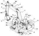
- 1 is a perspective view showing a work machine including a first embodiment of a hydraulic control device for a work machine according to the present invention.
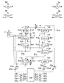
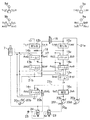
- 1 is a hydraulic control circuit diagram showing a first embodiment of a hydraulic control device for a work machine according to the present invention.
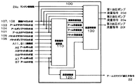
- It is a conceptual diagram which shows the structure of the controller which comprises 1st Embodiment of the hydraulic control apparatus of the working machine of this invention.
- It is a characteristic view showing an example of the map of the target operation calculating part of the controller which constitutes the 1st embodiment of the hydraulic control device of the working machine of the present invention.
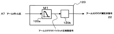
- It is a control block diagram which shows an example of the calculation content of the communication control part of the controller which comprises 1st Embodiment of the hydraulic control apparatus of the working machine of this invention.
- FIG. 4 is a hydraulic control circuit diagram showing a second embodiment of a hydraulic control device for a work machine according to the present invention.
- FIG. 1 is a perspective view showing a working machine provided with a first embodiment of a hydraulic control device for a working machine according to the present invention
- FIG. 2 shows a first embodiment of the hydraulic control device for the working machine according to the present invention.
- It is a hydraulic control circuit diagram.
- a hydraulic excavator provided with a first embodiment of the hydraulic control device for a working machine according to the present invention includes a lower traveling body 1 and an upper swing body 2 disposed on the lower traveling body 1. And a front work machine connected to the upper swing body 2 so as to be rotatable in the vertical direction and an engine 2A as a prime mover.
- the front work machine includes a boom 3 attached to the upper swing body 2, an arm 4 attached to the tip of the boom 3, and a bucket 5 attached to the tip of the arm 4.
- the front work machine includes a pair of boom cylinders 6 that drive the boom 3, an arm cylinder 7 that drives the arm 4, and a bucket cylinder 8 that drives the bucket 5.
- pressure oil discharged from a hydraulic pump device (not shown) is supplied via a control valve 10 in response to an operation of a first operation lever 9 a and a second operation lever 9 b provided in the cab of the upper swing body 1.
- the cylinder rods of the boom cylinder 6, the arm cylinder 7, and the bucket cylinder 8 are expanded and contracted by the pressure oil, so that the position and posture of the bucket 5 can be changed.
- the swing hydraulic motor 11 is rotated by the pressure oil, the upper swing body 2 rotates with respect to the lower traveling body 1.
- the control valve 10 includes a travel right direction control valve 12a, a travel left direction control valve 12b, a boom first direction control valve 13a, a boom second direction control valve 13b, and an arm first direction control valve, which will be described later. 14b, the arm second direction control valve 14a, the arm third direction control valve 14c, the bucket direction control valve 15a, and the turning direction control valve 16c.
- the engine 2A is provided with a rotation speed sensor 2Ax that detects the engine rotation speed.
- the boom cylinder 6 is provided with a pressure sensor A6 for detecting the pressure in the bottom side oil chamber and a pressure sensor B6 for detecting the pressure in the rod side oil chamber.
- the arm cylinder 7 is provided with a pressure sensor A7 as a load acquisition unit for detecting the pressure in the bottom side oil chamber and a pressure sensor B7 for detecting the pressure in the rod side oil chamber.
- the bucket cylinder 8 is provided with a pressure sensor A8 for detecting the pressure in the bottom side oil chamber and a pressure sensor B8 for detecting the pressure in the rod side oil chamber.
- the swing hydraulic motor 11 includes pressure sensors A11 and B11 for detecting left and right swing pressures. The pressure signals detected by these pressure sensors A6 to 8, B6 to 8, A11, and B11 and the engine speed detected by the rotation speed sensor 2Ax are input to the controller 100 described later.
- the pump device 20 constituting the first embodiment of the hydraulic control device for a work machine according to the present invention includes a first hydraulic pump 20a and a second hydraulic pump 20b that are variable displacement hydraulic pumps. And a third hydraulic pump 20c.
- the first to third hydraulic pumps 20a to 20c are driven by the engine 2A.
- the first hydraulic pump 20a includes a regulator 20d that is driven by a command signal from the controller 100, which will be described later, and supplies the controlled discharge flow of pressure oil to the first pump line 21a.
- the second hydraulic pump 20b includes a regulator 20e that is driven by a command signal from the controller 100, which will be described later, and supplies a controlled pressure oil discharge flow rate to the second pump line 21b.
- the third hydraulic pump 20c includes a regulator 20f that is driven by a command signal from the controller 100, which will be described later, and supplies a controlled pressure oil discharge flow rate to the third pump line 21c.
- the first pump line 21a communicating with the discharge port of the first hydraulic pump 20a includes a traveling right direction control valve 12a, a bucket direction control valve 15a, an arm second direction control valve 14a, and a boom first.
- a direction control valve 13a is arranged.
- the traveling right direction control valve 12a is configured as a tandem circuit, and the remaining bucket direction control valve 15a, the arm second direction control valve 14a, and the boom first direction control valve 13a are configured as a parallel circuit. is doing.
- a second direction control valve for boom 13b In the second pump line 21b communicating with the discharge port of the second hydraulic pump 20b, a second direction control valve for boom 13b, a first direction control valve for arm 14b, and a left direction control valve for traveling 12b are arranged. Yes.
- the boom second directional control valve 13b and the arm first directional control valve 14b are configured as parallel circuits, and the traveling left directional control valve 12b is configured as a parallel-tandem circuit. However, the parallel circuit of the traveling left directional control valve 12b is used.
- the check valve 17 and the throttle 18 that allow only the inflow from the second hydraulic pump 20b side are arranged. Further, the travel left direction control valve 12 b can communicate with the first hydraulic pump 20 via the travel communication valve 19.
- the arm third direction control valve 14c and the turning direction control valve 16c are arranged in the third pump line 21c communicating with the discharge port of the third hydraulic pump 20c.
- the turning direction control valve 16c is configured as a tandem circuit giving priority.
- the outlet port of the first boom direction control valve 13a and the outlet port of the second boom direction control valve 13b communicate with the boom cylinder 6 via a merging passage (not shown). Further, the outlet port of the arm second direction control valve 14a, the outlet port of the arm first direction control valve 14b, and the outlet port of the arm third direction control valve are connected to the arm cylinder 7 via a merge passage (not shown). Communicate. The outlet port of the bucket direction control valve 15 a communicates with the bucket cylinder 5, and the outlet port of the turning direction control valve 16 c communicates with the turning hydraulic motor 11.
- each of the first operating lever 9a to the fourth operating lever 9d has a pilot valve (not shown) inside, and generates a pilot pressure corresponding to the operation amount of the tilting operation of each operating lever.
- the pilot pressure from each operation lever is supplied to the operation part of each direction control valve.
- the pilot lines indicated by broken lines BkC and BkD are connected to the operating portion of the bucket direction control valve 15a, and the bucket cloud pilot pressure generated according to the operation amount of the tilting operation of the operating lever The bucket dump pilot pressure is supplied. Further, from the first operating lever 9a, pilot lines indicated by broken lines BmD and BmU are connected to the operating portions of the first boom direction control valve 13a and the second boom direction control valve 13b, and the operating lever is tilted. A boom raising pilot pressure and a boom lowering pilot pressure generated according to the operation amount are supplied.
- the pilot lines indicated by broken lines BkC and BkD are provided with a pressure sensor 105 for detecting the bucket cloud pilot pressure and a pressure sensor 106 for detecting the bucket dump pilot pressure.
- a pilot line indicated by broken lines BmD and BmU is provided with a pressure sensor 101 for detecting a boom raising pilot pressure and a pressure sensor 102 for detecting a boom lowering pilot pressure.
- These pressure sensors 101, 102, 105, and 106 are operation instruction detection units, and the pressure signals detected by these pressure sensors 101, 102, 105, and 106 are input to the controller 100.
- pilot lines indicated by broken lines AmC and AmD are connected to the operating portions of the arm first direction control valve 14b, the arm second direction control valve 14a, and the arm third direction control valve 14c.
- the arm cloud pilot pressure and the arm dump pilot pressure generated according to the operation amount of the tilting operation of the operation lever are supplied.
- a pilot line indicated by broken lines SwR and SwL is connected to the operating portion of the turning direction control valve 16c from the second operating lever 9b, and the turning right pilot generated according to the operation amount of the tilting operation of the operating lever. Pressure and turning left pilot pressure are supplied.
- a pressure sensor 103 for detecting an arm cloud pilot pressure and a pressure sensor 104 for detecting an arm dump pilot pressure are provided on pilot lines indicated by broken lines AmC and AmD.
- the arm cloud pilot line connected to the operation portion of the arm third direction control valve 14c is provided with an arm 3 cloud pressure reducing valve 22 for limiting or blocking the supplied arm cloud pilot pressure oil.
- a pressure sensor 108 for detecting the turning right pilot pressure and a pressure sensor 107 for detecting the turning left pilot pressure are provided on the pilot lines indicated by broken lines SwR and SwL.
- These pressure sensors 103, 104, 107 and 108 are operation instruction detection units, and the pressure signals detected by these pressure sensors 103, 104, 107 and 108 are input to the controller 100.
- the pilot lines indicated by broken lines TrRF and TrRR are connected to the operating portion of the traveling right direction control valve 12a, and the traveling right forward is generated according to the operation amount of the tilting operation of the operating lever. Pilot pressure and traveling right reverse pilot pressure are supplied.
- pilot lines indicated by broken lines TrLF and TrLR are connected to the operating portion of the traveling left direction control valve 12b, and the traveling left forward pilot generated according to the operation amount of the tilting operation of the operating lever. Pressure and traveling left reverse pilot pressure are supplied.
- the hydraulic control apparatus in the present embodiment includes a controller 100.
- the controller 100 inputs the engine rotation speed from the rotation speed sensor 2Ax shown in FIG. 1, and inputs the pilot pressure signal of each pilot line from the pressure sensors 101 to 108 described above. Further, pressure signals of the respective actuators are inputted from the pressure sensors A6 to 8, B6 to 8, A11, and B11 shown in FIG.
- the controller 100 outputs command signals to the regulator 20d of the first hydraulic pump 20a, the regulator 20e of the second hydraulic pump 20b, and the regulator 20f of the third hydraulic pump 20c, respectively.
- the discharge flow rate of 20c is controlled.
- the controller 100 outputs a command signal to the operation unit of the arm 3 cloud pressure reducing valve 22 to limit or cut off the pressure of the arm cloud pilot line Amc supplied to the operation unit of the arm third direction control valve 14c. To control.
- this command signal increases, the pilot pressure supplied to the operating portion of the arm third direction control valve 14c is shut off. As a result, the communication between the third hydraulic pump 20c and the arm cylinder 7 is blocked, and the pressure oil from the third pump line 21C returns to the tank.
- FIG. 3 is a conceptual diagram showing the configuration of a controller constituting the first embodiment of the hydraulic control device for a work machine according to the present invention.
- FIG. 4 shows the first embodiment of the hydraulic control device for the work machine according to the present invention.
- FIG. 5 is a characteristic diagram showing an example of a map of the target operation calculation unit of the controller that constitutes, and FIG. 5 shows an example of calculation contents of the communication control unit of the controller that constitutes the first embodiment of the hydraulic control device for the work machine of the present invention. It is a control block diagram shown.
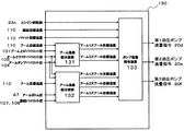
- the controller 100 includes command signals for a target operation calculation unit 110 that calculates each target flow rate from each pilot pressure and each load pressure, and an arm 3 cloud pressure reducing valve 22 that controls the communication state of the control valve 10.
- a target operation calculation unit 110 that calculates each target flow rate from each pilot pressure and each load pressure
- an arm 3 cloud pressure reducing valve 22 that controls the communication state of the control valve 10.
- each of the first to third hydraulic pumps 20a to 20c is connected.
- a flow rate control unit 130 as a pump flow rate control unit that calculates a flow rate command signal.
- the flow rate control unit 130 outputs a command signal to the regulators 20d to 20f of each hydraulic pump, and controls the discharge flow rates of the first to third hydraulic pumps 20a to 20c, respectively.
- the target operation calculation unit 110 increases each target flow rate according to an increase in each input pilot pressure, and decreases each target flow rate according to an increase in each input load pressure.
- the target flow rate is calculated. Further, at the time of the interlocking operation, calculation is performed so that each target flow rate becomes smaller than that in the case of the single operation.
- a map for calculating the reference flow rate from the pilot pressure shown in FIG. 4 is stored for each actuator.
- the turning target flow rate Qsw is calculated from the turning pilot pressure that is a value obtained by selecting the maximum values of the turning right pilot pressure and the turning left pilot pressure.
- the arm cloud reference flow rate Qamc0 is calculated from the arm cloud pilot pressure
- the dump reference flow rate Qamd0 is calculated from the arm dump pilot pressure.
- the boom raising reference flow rate Qbmu0 is calculated from the boom raising pilot pressure.
- the bucket cloud reference flow rate Qbkc0 is calculated from the bucket cloud pilot pressure
- the bucket dump reference flow rate Qbkd0 is calculated from the bucket dump pilot pressure.
- the target motion calculation unit 110 calculates the boom target flow rate Qbm from the turning target flow rate Qsw using the calculation formula number 1.
- Qbmmax is an upper limit value of the boom flow rate and is set in accordance with the maximum boom raising speed.
- kswbm is a boom flow rate reduction coefficient, and the boom target flow rate Qbm decreases as the turning target flow rate Qsw increases.
- a map in which the upper limit value Qbmmax of the boom flow rate decreases as the turning target flow rate Qsw increases may be used.
- the target motion calculation unit 110 calculates the turning power Lsw and the boom power Lbm using the formulas 2 and 3, respectively.
- Psw is the turning pressure, and is a value obtained by selecting the meter-in side pressure from the turning left pressure and the turning right pressure detected by the pressure sensors A11 and B11.
- Pbmb is the boom bottom pressure, which is the pressure in the bottom oil chamber of the boom cylinder 6 detected by the pressure sensor A6.
- the target motion calculation unit 110 calculates the bucket power upper limit value Lbkmax and the arm power upper limit value Lammax using the equations 4 and 5, respectively.
- Lmax is the total power upper limit value of the system.
- kbk indicates a bucket power coefficient
- kam indicates an arm power coefficient.
- the bucket power coefficient kbk and the arm power coefficient kam are calculated using the bucket cloud pilot pressure BkC, the bucket dump pilot pressure BkD, the arm cloud pilot pressure AmC, the arm dump pilot pressure AmD and the arithmetic expression number 6.
- the target operation calculation unit 110 calculates the bucket target flow rate Qbk using the bucket cloud reference flow rate Qbkc0, the bucket dump reference flow rate Qbkd0, the bucket power upper limit Lbkmax, and the arithmetic expression number 7. In addition, the target operation calculation unit 110 calculates the arm target flow rate Qam using the arm cloud reference flow rate Qamc0, the arm dump reference flow rate Qamd0, the arm power upper limit Lammax, and the arithmetic expression number 8.
- Pbk is a value obtained by selecting the meter-in side pressure from the pressure in the bottom side oil chamber of the bucket cylinder 8 and the pressure in the rod side oil chamber detected by the pressure sensors A8 and B8.
- Pam is a value obtained by selecting the meter-in side pressure from the pressure of the bottom side oil chamber of the arm cylinder 7 and the pressure of the rod side oil chamber detected by the pressure sensors A7 and B7.
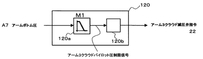
- the communication control unit 120 includes a first function generator 120a and a solenoid valve drive command conversion unit 120b.
- the first function generator 120a inputs the pressure in the bottom oil chamber of the arm cylinder 7 detected by the pressure sensor A7.
- the limit characteristic of the arm 3 cloud pilot pressure with respect to the pressure in the bottom oil chamber of the arm cylinder 7 is stored in advance as a map M1 in the table.
- the map M1 has a characteristic of decreasing the arm 3 cloud pilot pressure as the pressure in the bottom side oil chamber of the arm cylinder 7 increases.
- the limit characteristic signal of the arm 3 cloud pilot pressure calculated by the first function generator 120a is output to the solenoid valve drive command converter 120b.
- the electromagnetic valve drive command conversion unit 120b receives the limit characteristic signal of the arm 3 cloud pilot pressure from the first function generator 120a, and calculates the command signal of the arm 3 cloud pressure reducing valve 22 corresponding to the limit characteristic signal. Specifically, when the command signal of the arm 3 cloud pressure reducing valve 22 increases, the pilot pressure supplied to the operating portion of the arm third direction control valve 14c decreases and is cut off, so that the input signal increases. It has the characteristic that the output signal increases. The command signal calculated by the electromagnetic valve drive command conversion unit 120b is output to the operation unit of the arm 3 cloud pressure reducing valve 22.
- the pilot pressure supplied to the operating portion of the arm third direction control valve 14c decreases as the pressure in the bottom oil chamber of the arm cylinder 7 increases.
- the value of the pressure in the bottom oil chamber of the arm cylinder 7 that starts to decrease from a constant value in the limit characteristic of the arm 3 cloud pilot pressure may cause the leakage loss of the hydraulic pump to exceed the friction loss of the hydraulic pump. It is desirable that the pressure be higher than a certain pump discharge pressure, and is set based on the loss characteristic of the hydraulic pump.
- FIG. 6 is a conceptual diagram showing the configuration of the flow control unit of the controller constituting the first embodiment of the hydraulic control device for the work machine of the present invention
- FIG. 7 is the first diagram of the hydraulic control device for the work machine of the present invention
- FIG. 8 is a control block diagram showing an example of calculation contents of the boom flow rate distribution calculation unit of the controller constituting the embodiment
- FIG. 8 is an arm target of the controller constituting the first embodiment of the hydraulic control device for a work machine according to the present invention.
- FIG. 9 is a control block diagram showing an example of the calculation contents of the flow rate distribution calculation unit, and FIG.
- FIG. 9 shows an example of the calculation contents of the pump flow rate command calculation unit of the controller constituting the first embodiment of the hydraulic control device for the work machine of the present invention. It is a control block diagram shown. 6 to 9, the same reference numerals as those shown in FIGS. 1 to 5 are the same parts, and detailed description thereof is omitted.
- the flow rate control unit 130 distributes the target flow rate for each of the plurality of directional control valves of the arm 4 and the boom flow rate distribution calculation unit 131 for distributing and calculating the target flow rate of each of the directional control valves of the boom 3.
- the first to third hydraulic pumps calculate the flow rate of each pump based on the calculated target flow rates and the flow rates of the respective pumps based on the calculated target flow rates and output the command signals to the regulators 20d to 20f of the respective hydraulic pumps.
- a pump flow rate command calculator 133 for controlling the discharge flow rates 20a to 20c.
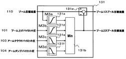
- the boom flow rate distribution calculation unit 131 includes a first function generator 131a, a minimum value selection unit 131b, a subtractor 131c, a second function generator 131d, a third function generator 131e, and a fourth function generator 131f. .
- the first function generator 131a inputs the boom target flow rate from the target motion calculation unit 110.
- the boom 2 spool target flow rate with respect to the boom target flow rate is stored in advance as a map M3a in the table.
- the map M3a has a characteristic of increasing the boom 2 spool target flow rate as the boom target flow rate increases.
- the boom 2 spool target flow rate may be set to half the boom target flow rate.
- the boom 1 spool target flow rate and the boom 2 spool target flow rate are each half of the boom target flow rate unless the restriction described later is applied.
- the calculated boom 2 spool target flow rate signal is output to the minimum value selection unit 131b.
- the minimum value selection unit 131b includes a boom 2 spool target flow rate signal from the first function generator 131a, a signal from the second function generator 131d described later, a limit signal from the third function generator 131e, and a fourth signal.
- the limit signal from the function generator 131f is input, the minimum value among these is calculated, and the minimum value is output to the subtractor 131c and the pump flow rate command calculation unit 133 as the boom 2 spool target flow rate.
- the subtractor 131c inputs the boom target flow rate from the target operation calculation unit 110 and the boom 2 spool target flow rate from the minimum value selection unit 131b, and subtracts the boom 2 spool target flow rate from the boom target flow rate. Calculate the spool target flow rate.
- the calculated boom 1 spool target flow rate signal is output to the pump flow rate command calculation unit 133.
- the second function generator 131d receives the boom raising pilot pressure detected by the pressure sensor 101, and outputs a limit signal to the minimum value selection unit 131b.
- an upper limit value of the boom 2 spool target flow rate with respect to the boom raising pilot pressure is stored in advance as a map M3b in the table.
- the map M3b is substantially proportional to the meter-in opening characteristic of the boom second direction control valve 13b, and increases according to the boom raising pilot pressure. That is, the upper limit value of the boom 2 spool target flow rate is increased in accordance with the opening of the boom second direction control valve 13c.
- the third function generator 131e receives the arm cloud pilot pressure detected by the pressure sensor 103, and outputs a signal obtained from the map M3c stored in the table in advance to the minimum value selection unit 131b.
- the map M3c is substantially proportional to the meter-in opening characteristic of the arm first direction control valve 14b with respect to the arm cloud pilot pressure, and the upper limit of the boom 2 spool flow rate is reduced according to the arm cloud pilot pressure.
- the fourth function generator 131f receives the arm dump pilot pressure detected by the pressure sensor 104 and outputs a signal obtained from the map M3d stored in the table in advance to the minimum value selection unit 131b.
- the map M3d is substantially proportional to the meter-in opening characteristic of the arm first directional control valve 14b with respect to the arm dump pilot pressure, and the upper limit value of the boom 2 spool flow rate is reduced according to the arm dump pilot pressure.
- the boom flow rate distribution calculation unit 131 limits the boom 2 spool target flow rate by these boom 2 spool flow rate upper limit values, and subtracts the boom 2 spool target flow rate from the boom target flow rate to calculate the boom 1 spool target flow rate.
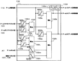
- the arm flow rate distribution calculator 132 includes a first function generator 132a, a first minimum value selector 132b, a first subtractor 132c, a second function generator 132d, a third function generator 132e, and a first maximum value selector 132f. , A fourth function generator 132g, a second minimum value selector 132h, a second subtractor 132i, a fifth function generator 132J, a sixth function generator 132k, a second maximum value selector 132L, and a seventh function generator 132m. And an eighth function generator 132n.
- the first function generator 132a and the fourth function generator 132g input the arm target flow rate from the target motion calculation unit 110.
- the arm 2 spool target flow rate with respect to the arm target flow rate is stored in advance as a map M4a in the table
- the fourth function generator 132g the arm 3 spool target flow rate with respect to the arm target flow rate is stored in the table in advance. It is stored as a map M4b.
- the maps M4a and M4b have characteristics that increase the arm 2 and 3 spool target flow rates as the arm target flow rate increases.
- the arm 2 and 3 spool target flow rate may be set to one third of the arm target flow rate.
- the arm 1 spool target flow rate, the arm 2 spool target flow rate, and the arm 3 spool target flow rate are each one third of the arm target flow rate unless the restriction described later is applied.
- the calculated arm 2 spool target flow rate signal is output to the first minimum value selector 132b.
- the calculated arm 3 spool target flow rate signal is output to the second minimum value selector 132h.
- the first minimum value selection unit 132b receives an arm 2 spool target flow rate signal from the first function generator 132a and a limit signal from a first maximum value selection unit 132f, which will be described later, and sets a minimum value among them.
- the minimum value is output as an arm 2 spool target flow rate signal to the first subtractor 132c and the pump flow rate command calculation unit 133.
- the first subtractor 132c inputs the arm target flow rate from the target motion calculation unit 110 and the arm 2 spool target flow rate from the first minimum value selection unit 132b, and subtracts the arm 2 spool target flow rate from the arm target flow rate. Then, the arm 1 spool target flow rate reference signal is calculated. The calculated arm 1 spool target flow rate reference signal is output to the second subtractor 132i.
- the second function generator 132d receives the arm cloud pilot pressure detected by the pressure sensor 103, and outputs a signal obtained from the map M4c stored in advance in the table to the first maximum value selector 132f.
- the map M4c is substantially proportional to the meter-in opening characteristic of the arm second direction control valve 14a with respect to the arm cloud pilot pressure, and the arm 2 spool flow rate upper limit value is increased in accordance with the arm cloud pilot pressure.
- the third function generator 132e inputs the arm dump pilot pressure detected by the pressure sensor 104, and outputs a signal obtained from the map M4d stored in the table in advance to the first maximum value selector 132f.
- the map M4d is substantially proportional to the meter-in opening characteristic of the arm second direction control valve 14a with respect to the arm dump pilot pressure, and the arm 2 spool flow rate upper limit value is increased in accordance with the arm dump pilot pressure.
- the first maximum value selection unit 132f receives the output of the second function generator 132d and the output of the third function generator 132e, calculates the maximum value of these, and selects the maximum value as the first minimum value selection. To the unit 132b.
- the second minimum value selection unit 132h includes an arm 3 spool target flow rate signal from the fourth function generator 132g, a limit signal from a second maximum value selection unit 132L described later, a seventh function generator 132m, and an eighth function.
- the limit signal from the generator 132n is input, the minimum value is calculated, and the minimum value is output to the second subtractor 132i and the pump flow rate command calculation unit 133 as the arm 3 spool target flow rate signal. .
- the second subtractor 132i receives the arm 1 spool target flow rate reference signal calculated by the first subtractor 132c and the arm 3 spool target flow rate from the second minimum value selection unit 132h, and from the arm 1 spool target flow rate reference signal.
- the arm 1 spool target flow rate reference signal is calculated by subtracting the arm 3 spool target flow rate.
- the calculated arm 1 spool target flow rate signal is output to the pump flow rate command calculation unit 133.
- the fifth function generator 132J receives the arm cloud pilot pressure detected by the pressure sensor 103, and outputs a signal obtained from the map M4f stored in the table in advance to the second maximum value selector 132L.
- the map M4f is substantially proportional to the meter-in opening characteristic of the arm third direction control valve 14c with respect to the arm cloud pilot pressure, and the arm 3 spool flow rate upper limit value is increased in accordance with the arm cloud pilot pressure. Note that the characteristics of the map M4f are set higher in the input value (arm cloud pilot pressure) at which the output rises than the characteristics of the map M4c.
- the sixth function generator 132k receives the arm dump pilot pressure detected by the pressure sensor 104, and outputs a signal obtained from the map M4g stored in the table in advance to the second maximum value selector 132L.
- the map M4g is substantially proportional to the meter-in opening characteristic of the arm third direction control valve 14c with respect to the arm dump pilot pressure, and the arm 3 spool flow rate upper limit value is increased in accordance with the arm dump pilot pressure. Note that the characteristics of the map M4g are set higher in the input value (arm dump pilot pressure) at which the output rises than the characteristics of the map M4d.
- the arm 2 spool target flow rate signal is generated first, and after the operation amount of the second operation lever 9b is increased, the arm 3 spool target flow is increased. A flow signal is generated.
- the second maximum value selection unit 132L receives the output of the fifth function generator 132J and the output of the sixth function generator 132k, calculates the maximum value of these, and selects the maximum value as the second minimum value selection. To the unit 132h.
- the seventh function generator 132m inputs the pressure of the bottom side oil chamber of the arm cylinder 7 detected by the pressure sensor A7, and sends a signal obtained from the map M4i stored in the table in advance to the second minimum value selection unit 132h. Output.
- the arm 3 spool flow rate upper limit value is decreased in accordance with the pressure in the bottom side oil chamber of the arm cylinder 7.
- the eighth function generator 132b inputs the maximum value of the turning right pilot pressure and the turning left pilot pressure detected by the pressure sensors 107 and 108 as the turning pilot pressure, and obtains it from the map M4h stored in the table in advance. Is output to the second minimum value selector 132h.
- the map M4h is substantially proportional to the center bypass opening characteristic of the turning direction control valve 16c with respect to the turning pilot pressure, and decreases the arm 3 spool flow rate upper limit value in accordance with the turning pilot pressure.
- the arm flow rate distribution calculation unit 132 calculates the arm 1-3 spool target flow rate based on the arm target flow rate calculated by the target operation calculation unit 110, the arm cloud pilot pressure, the arm dump pilot pressure, and the like.
- the map M4c of the second function generator 132d and the map M4f of the fifth function generator 132J, and the map M4d of the third function generator 132e and the map M4g of the sixth function generator 132k the output rising point with respect to the input Therefore, as the operation amount of the second operation lever 9b for operating the arm 4 increases, the arm 1 spool target flow rate is sequentially generated.
- the arm 1 spool target flow rate and the arm 2 spool target flow rate are generated according to the operation amount of the second operation lever 9b, and when the operation amount further increases, the arm 3 spool target flow rate is generated.
- the pump flow rate command calculator 133 includes a first maximum value selector 133a, a first divider 133b, a first function generator 133c, a second maximum value selector 133d, a second divider 133e, and a second function generator 133f.
- a third maximum value selector 133g, a third divider 133h, and a third function generator 133i are provided.
- the first maximum value selection unit 133a is configured to output a bucket target flow rate signal from the target motion calculation unit 110, a boom 1 spool target flow rate signal from the boom flow rate distribution calculation unit 131, and an arm 2 spool target flow rate signal from the arm flow rate distribution calculation unit 132. Are calculated, the maximum value among them is calculated, and the maximum value is output to the first divider 133b as the first pump target flow rate.
- the first divider 133b receives the first pump target flow rate from the first maximum value selection unit 133a and the engine speed detected by the rotation speed sensor 2Ax, and divides the first pump target flow rate by the engine speed. Thus, the first pump target command is calculated.
- the calculated first pump target command signal is output to the first function generator 133c.
- the first function generator 133c receives the first pump target command signal calculated by the first divider 133b, and uses the signal obtained from the map M5a stored in the table in advance as the first pump flow rate command signal to the regulator 20d. Output. Thereby, the discharge flow rate of the first hydraulic pump 20a is controlled.
- the second maximum value selector 133d receives the boom 2 spool target flow signal from the boom flow distribution calculator 131 and the arm 1 spool target flow signal from the arm flow distribution calculator 132, and sets the maximum value among these. The maximum value is calculated and output to the second divider 133e as the second pump target flow rate.
- the second divider 133e receives the second pump target flow rate from the second maximum value selector 133d and the engine speed detected by the rotation speed sensor 2Ax, and divides the second pump target flow rate by the engine speed. Thus, the second pump target command is calculated.
- the calculated second pump target command signal is output to the second function generator 133f.
- the second function generator 133f receives the second pump target command signal calculated by the second divider 133e, and uses the signal obtained from the map M5b stored in the table in advance as the second pump flow rate command signal to the regulator 20e. Output. Thereby, the discharge flow rate of the second hydraulic pump 20b is controlled.
- the third maximum value selection unit 133g receives the turning target flow rate signal from the target motion calculation unit 110 and the arm 3 spool target flow rate signal from the arm flow distribution calculation unit 132, calculates the maximum value of these, The maximum value is output to the third divider 133h as the third pump target flow rate.
- the third divider 133h receives the third pump target flow rate from the third maximum value selector 133g and the engine speed detected by the rotation speed sensor 2Ax, and divides the third pump target flow rate by the engine speed. Thus, the third pump target command is calculated.
- the calculated third pump target command signal is output to the third function generator 133i.
- the third function generator 133i inputs the third pump target command signal calculated by the third divider 133b, and uses the signal obtained from the map M5c stored in the table in advance as the third pump flow rate command signal to the regulator 20f. Output. Thereby, the discharge flow rate of the third hydraulic pump 20c is controlled.
- the arm 2 spool target flow rate is input to the first maximum value selection unit 133a
- the arm 1 spool target flow rate is input to the second maximum value selection unit 133d
- the third maximum value selection unit 133g is input to calculate the first pump target flow rate to the third pump target flow rate, respectively.
- the arm flow distribution calculation unit 132 generates the arm 1 spool target flow rate first in accordance with the increase in the operation amount of the second operation lever 9b that operates the arm 4, and then the arm 2 A spool target flow rate is generated, and finally an arm 3 spool target flow rate is generated.
- the second pump flow rate command signal is generated first in response to the increase in the operation amount, and then the first pump flow rate command A signal is generated, and finally a third pump flow rate command signal is generated.
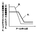
- FIG. 10 is a characteristic diagram showing an example of a map of the arm flow rate distribution calculation unit of the controller constituting the first embodiment of the hydraulic control device for a work machine according to the present invention.
- the horizontal axis indicates the pressure in the bottom oil chamber of the arm cylinder 7
- the vertical axis indicates the target flow rate of the arm 3 spool.
- a characteristic line A indicated by a solid line indicates a limit characteristic signal of the arm 3 cloud pilot pressure of the map M1 set in the first function generator 120a of the communication control unit 120
- a characteristic line B indicated by a broken line indicates a seventh characteristic line B.
- the map M4i set in the function generator 132m shows the upper limit restriction characteristic of the arm 3 spool target flow rate with respect to the pressure in the bottom side oil chamber of the arm cylinder 7.
- the map M4i (characteristic line B) reduces the upper limit value of the arm 3 spool target flow rate as the pressure in the bottom side oil chamber of the arm cylinder 7 increases.
- the operation direction is the same as the map M1 (characteristic line A) for reducing the limit characteristic of the arm 3 cloud pilot pressure as the oil chamber pressure increases.
- the map M4i (characteristic line B) starts reducing the upper limit of the arm 3 spool target flow rate before the descent of the characteristic line A (in the region where the pressure in the bottom side oil chamber of the arm cylinder 7 is small).
- the arm 3 cloud pressure reducing valve 22 operates and the center bypass opening of the arm third direction control valve 14c starts to open.
- the upper limit of the arm 3 spool flow rate is lowered and the discharge flow rate of the third hydraulic pump 20c is reduced until the center bypass opening of the arm third direction control valve 14c is opened.
- the bleed-off loss that occurs in the arm third direction control valve 14c can be reduced.
- the change in meter-in flow rate to the arm cylinder 7 at the beginning of opening of the center bypass opening of the arm third direction control valve 14c becomes small, and the shock at this time can be reduced.
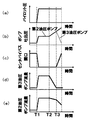
- FIG. 11 is a characteristic diagram for explaining an example of the operation related to the pump flow rate control unit in the first embodiment of the hydraulic control device for a work machine according to the present invention.
- the horizontal axis indicates time, and the vertical axis indicates (a) pilot pressure, (b) discharge pressure of the hydraulic pump, (c) third directional control valve for arm 14c, center bypass opening, (d).
- the third hydraulic pump discharge flow rate and (e) the fourth hydraulic pump discharge flow rate are shown.
- the solid line in (b) indicates the discharge pressure characteristic of the second hydraulic pump 20b, and the broken line indicates the discharge pressure characteristic of the third hydraulic pump 20c.
- the time T1 is the time when the arm cloud operation is started
- the time T2 is the time when the pressure of the bottom side oil chamber of the arm cylinder 7 increases due to the bucket contacting the excavation surface
- the time T3 is the arm
- the time when the pressure in the bottom side oil chamber of the cylinder 7 further increased is shown.
- the operation of the first hydraulic pump 20a will be omitted.
- the arm cloud pilot pressure rises as shown in (a).
- the arm first direction control valve 14b and the arm third direction control valve 14c operate, the arm cylinder 7 and each hydraulic pump communicate with each other, and the pump discharge pressure shown in FIG. The pressure rises up to the pressure corresponding to the oil chamber pressure.
- the center bypass opening of the arm third direction control valve 14c is closed as shown in FIG.
- the discharge flow rate of the third hydraulic pump 20c and the discharge flow rate of the second hydraulic pump 20b increase, and the arm 4 operates.
- the center bypass opening of the arm third direction control valve 14c starts to open, and the discharge pressure of the third hydraulic pump 20c starts to decrease as shown in (b).
- the discharge flow rate of the third hydraulic pump 20c after time T3 shown in (d) is preferably a standby flow rate.
- the standby flow rate in the present embodiment refers to the minimum discharge flow rate of the pressure oil that must be flowed to protect the hydraulic pump that operates.
- the leakage flow rate of a hydraulic pump increases approximately in proportion to the discharge pressure, and the higher the discharge pressure, the greater the influence of the leakage flow rate on the loss of the hydraulic pump. Therefore, at the time of high load, rather than driving the arm cylinder 7 with both the third hydraulic pump 20c and the second hydraulic pump 20b, only the second hydraulic pump 20b is used as in the hydraulic control device according to the present embodiment. Thus, driving the arm cylinder 7 can reduce the total pump loss and can save energy.
- the discharge flow rate of the third hydraulic pump 20c is reduced before the center bypass opening of the arm third direction control valve 14c starts to open, the bleed-off loss generated in the arm third direction control valve 14c is reduced. Can be reduced. Further, the change in meter-in flow rate to the arm cylinder 7 at the beginning of opening of the center bypass opening of the arm third direction control valve 14c becomes small, and the shock at this time can be reduced.
- the first hydraulic pump increases as the load on the first hydraulic actuator (arm cylinder 7) increases. Since the discharge flow rate of the pump 20c) is reduced and the first control valve (arm third direction control valve 14c) is driven to increase the communication area between the first hydraulic pump and the tank, the first hydraulic pump The discharge pressure of the (third hydraulic pump 20c) can be lowered, and the total leakage flow rate of the pump can be reduced. As a result, the ineffective flow rate discharged from the first hydraulic pump (third hydraulic pump 20c) can be reduced. As a result, an energy-saving hydraulic control device for a work machine can be provided.
- the first hydraulic pump (third hydraulic pump) according to the load of the first hydraulic actuator (arm cylinder 7). Since the discharge flow rate of the first hydraulic pump (third hydraulic pump 20c) is reduced before the communication area between the tank 20c) and the tank is expanded, the first control valve (arm third direction control valve 14c) Can reduce the bleed-off loss. Further, the change in the meter-in flow rate to the first hydraulic actuator (arm cylinder 7) when the first control valve (arm third direction control valve 14c) is opened and closed is reduced, and the shock at this time can be reduced.
- FIG. 12 is a hydraulic control circuit diagram showing a second embodiment of the hydraulic control device for a work machine according to the present invention.
- FIG. 12 since the same reference numerals as those shown in FIGS. 1 to 11 are the same parts, detailed description thereof will be omitted.
- the overall system configuration is substantially the same as that of the first embodiment, but the hydraulic pressure is obtained only by the hydraulic circuit without using the controller 100.
- the point which comprised the control apparatus differs from 1st Embodiment.
- the regulator 20f of the third hydraulic pump 20c is operated by a sub-regulator 20g driven by pilot hydraulic pressure. Pilot pressure oil is supplied to the sub-regulator 20g from the pilot hydraulic power source 25 via the first switching valve 23. In accordance with the supply of pressure oil to the sub-regulator 20g, the regulator 20f controls the discharge flow rate of the third hydraulic pump 20c in the decreasing direction.
- the first switching valve 23 is a three-port two-position switching valve that introduces pressure oil from the bottom side oil chamber of the arm cylinder 7 into the operation portion and includes a spring on one side. Is connected to the outlet port, and an oil passage to the sub-regulator 20g is connected to the outlet port. An oil passage to the tank is connected to the drain port.
- the arm cloud pilot line connected to the operating portion of the arm third direction control valve 14c is provided with an arm 3 cloud pressure reducing valve 22b for limiting or blocking supplied arm cloud pilot pressure oil.
- the arm 3 cloud pressure reducing valve 22b is driven by pilot hydraulic pressure. Pilot pressure oil is supplied to the arm 3 cloud pressure reducing valve 22b from the pilot hydraulic pressure source 25 through the second switching valve 24. In response to the supply of pressure oil to the arm 3 cloud pressure reducing valve 22b, the arm 3 cloud pressure reducing valve 22b expands the communication area between the third hydraulic pump 20c and the tank.
- the second switching valve 24 is a three-port two-position switching valve that introduces pressure oil from the bottom side oil chamber of the arm cylinder 7 to the operation portion and includes a spring on one side. Is connected to the oil passage, and the oil passage to the operation portion of the arm 3 cloud pressure reducing valve 22b is connected to the outlet port. An oil passage to the tank is connected to the drain port.
- the 1st switching valve 23 is the direction of the 1st switching valve 23 with respect to the pressure increase of the pressure oil of the bottom side oil chamber of the arm cylinder 7 introduce
- the maximum value of the operating pilot pressure that drives the directional control valves arranged in the pump lines 21a, 21b, and 21c is detected, and the regulators 20d, 20e, and 20f are driven based on the detected values. You may do it.
- the present invention is not limited to the first and second embodiments described above, and includes various modifications.
- the above-described embodiment has been described in detail for easy understanding of the present invention, and is not necessarily limited to the one having all the configurations described.
- part of the configuration of one embodiment can be replaced with the configuration of another embodiment, and the configuration of another embodiment can be added to the configuration of one embodiment.
Abstract
Description
一般的に油圧ポンプの漏れ流量は吐出圧に応じて増加するので、吐出圧が高いほど油圧ポンプの全損失に対する漏れ流量の影響が大きくなる。そのため、負荷圧に応じて合流解除弁を作動させ、第3油圧ポンプの吐出圧を低下させると、ポンプ合計の漏れ流量を低減することはできる。しかしながら、上述した従来技術には、このときの第3油圧ポンプの流量制御に関する記述が無い。
図1に示すように、本発明の作業機械の油圧制御装置の第1の実施の形態を備えた油圧ショベルは、下部走行体1と、この下部走行体1上に配置される上部旋回体2と、この上部旋回体2に上下方向の回動可能に接続されるフロント作業機と原動機としてのエンジン2Aとを備えている。フロント作業機は、上部旋回体2に取り付けられるブーム3と、このブーム3の先端に取り付けられるアーム4と、このアーム4の先端に取り付けられるバケット5とを備えている。また、このフロント作業機は、ブーム3を駆動する一対のブームシリンダ6と、アーム4を駆動するアームシリンダ7と、バケット5を駆動するバケットシリンダ8とを備えている。
なお、ここで、アーム3クラウドパイロット圧力の制限特性で、一定値から減少開始するアームシリンダ7のボトム側油室の圧力の値は、油圧ポンプの漏れ損失が油圧ポンプの摩擦損失を上回る可能性があるポンプ吐出圧以上にすることが望ましく、油圧ポンプの損失特性を基に設定する。
本実施の形態でいうスタンバイ流量とは、運転する油圧ポンプを保護するために流さなければならない圧油の最少吐出流量をいう。
Claims (5)
- 第1の油圧アクチュエータと、前記第1の油圧アクチュエータと連通可能な第1の油圧ポンプおよび第2の油圧ポンプと、前記第1の油圧ポンプが吐出する圧油をタンクへ還流可能な第1の制御弁と、前記第1の油圧アクチュエータの負荷を検出する負荷検出部とを備えた作業機械の油圧制御装置であって、
前記負荷検出部が検出した検出信号を取り込み、前記第1の油圧アクチュエータの負荷の増加に応じて、前記第1の油圧ポンプと前記タンクとの連通面積を拡大するように前記第1の制御弁を駆動する制御弁駆動部と、
前記第1の油圧ポンプと前記第2の油圧ポンプとから前記第1の油圧アクチュエータへ圧油を供給している場合において、前記負荷検出部が検出した検出信号を取り込み、前記第1の油圧アクチュエータの負荷の増加に応じて、前記第1の油圧ポンプの吐出流量を低減する制御を行なう流量制御部とを備えた
ことを特徴とする作業機械の油圧制御装置。 - 請求項1に記載の作業機械の油圧制御装置において、
前記第1の油圧アクチュエータの負荷の増加に応じて、前記制御弁駆動部が前記第1の油圧ポンプと前記タンクとの連通面積を拡大するように前記第1の制御弁を駆動するよりも先に、前記流量制御部が前記第1の油圧ポンプの吐出流量を低減する制御を行なう
ことを特徴とする作業機械の油圧制御装置。 - 請求項1に記載の作業機械の油圧制御装置において、
前記流量制御部はさらに前記第2の油圧ポンプの吐出流量を低減制御可能であり、
前記第1の油圧アクチュエータの負荷の増加に応じて、前記第2の油圧ポンプの吐出流量を低減する制御を行なうよりも先に前記第1の油圧ポンプの吐出流量を低減する制御を行なう
ことを特徴とする油圧制御装置。 - 請求項1に記載の作業機械の油圧制御装置において、
前記第1の油圧アクチュエータの動作を指示する第1の操作部と、前記第1の操作部の操作量を検出する操作量検出部とを備え、
前記流量制御部は、前記操作量検出部が検出した検出信号を取り込み、前記第1の操作部の操作量の増加に応じて、前記第1の油圧ポンプから前記第1の油圧アクチュエータへ供給される圧油の流量よりも先に、前記第2の油圧ポンプから前記第1の油圧アクチュエータへ供給される圧油の流量を増加させる
ことを特徴とする油圧制御装置。 - 請求項1に記載の作業機械の油圧制御装置において、
前記流量制御部によって低減制御された後の前記第1の油圧ポンプの吐出流量は、前記第1の油圧ポンプのスタンバイ流量である
ことを特徴とする油圧制御装置。
Priority Applications (4)
| Application Number | Priority Date | Filing Date | Title |
|---|---|---|---|
| EP15857003.6A EP3217019B1 (en) | 2014-11-06 | 2015-08-28 | Hydraulic control device for operating machine |
| KR1020177004741A KR101894978B1 (ko) | 2014-11-06 | 2015-08-28 | 작업 기계의 유압 제어 장치 |
| CN201580044422.1A CN106574641B (zh) | 2014-11-06 | 2015-08-28 | 作业机械的液压控制装置 |
| US15/504,864 US10330128B2 (en) | 2014-11-06 | 2015-08-28 | Hydraulic control system for work machine |
Applications Claiming Priority (2)
| Application Number | Priority Date | Filing Date | Title |
|---|---|---|---|
| JP2014-226519 | 2014-11-06 | ||
| JP2014226519A JP6226851B2 (ja) | 2014-11-06 | 2014-11-06 | 作業機械の油圧制御装置 |
Publications (1)
| Publication Number | Publication Date |
|---|---|
| WO2016072135A1 true WO2016072135A1 (ja) | 2016-05-12 |
Family
ID=55908865
Family Applications (1)
| Application Number | Title | Priority Date | Filing Date |
|---|---|---|---|
| PCT/JP2015/074544 WO2016072135A1 (ja) | 2014-11-06 | 2015-08-28 | 作業機械の油圧制御装置 |
Country Status (6)
| Country | Link |
|---|---|
| US (1) | US10330128B2 (ja) |
| EP (1) | EP3217019B1 (ja) |
| JP (1) | JP6226851B2 (ja) |
| KR (1) | KR101894978B1 (ja) |
| CN (1) | CN106574641B (ja) |
| WO (1) | WO2016072135A1 (ja) |
Families Citing this family (4)
| Publication number | Priority date | Publication date | Assignee | Title |
|---|---|---|---|---|
| EP3249113B1 (en) * | 2014-12-19 | 2020-02-26 | Volvo Construction Equipment AB | System for measuring friction force of excavator swing device for supplying lubricating oil |
| JP2019008558A (ja) * | 2017-06-23 | 2019-01-17 | 国立大学法人 東京大学 | 油圧アクチュエータ及び油圧アクチュエータの圧力制御方法 |
| JP7165016B2 (ja) * | 2018-10-02 | 2022-11-02 | 川崎重工業株式会社 | 油圧ショベル駆動システム |
| JP7165074B2 (ja) * | 2019-02-22 | 2022-11-02 | 日立建機株式会社 | 作業機械 |
Citations (3)
| Publication number | Priority date | Publication date | Assignee | Title |
|---|---|---|---|---|
| JPH06123302A (ja) * | 1992-10-08 | 1994-05-06 | Kayaba Ind Co Ltd | 建設機械の油圧制御装置 |
| JPH11303809A (ja) * | 1998-04-20 | 1999-11-02 | Komatsu Ltd | 油圧駆動機械のポンプ制御装置 |
| JP2014020431A (ja) * | 2012-07-17 | 2014-02-03 | Komatsu Ltd | 油圧駆動システム |
Family Cites Families (16)
| Publication number | Priority date | Publication date | Assignee | Title |
|---|---|---|---|---|
| JPH08303407A (ja) * | 1995-05-09 | 1996-11-19 | Komatsu Ltd | 操作弁の合流回路 |
| JPH1113091A (ja) * | 1997-06-23 | 1999-01-19 | Hitachi Constr Mach Co Ltd | 建設機械の油圧駆動装置 |
| JP3607529B2 (ja) * | 1999-05-24 | 2005-01-05 | 日立建機株式会社 | 建設機械の油圧制御装置 |
| JP3901058B2 (ja) * | 2002-08-21 | 2007-04-04 | コベルコ建機株式会社 | 建設機械の油圧シリンダ制御装置 |
| SE0402233L (sv) * | 2004-07-26 | 2006-02-28 | Volvo Constr Equip Holding Se | Arrangemang och förfarande för styrning av ett arbetsfordon |
| GB2441258B (en) * | 2005-05-18 | 2010-01-27 | Komatsu Mfg Co Ltd | Hydraulic control device for construction machinery |
| JP4434159B2 (ja) * | 2006-03-02 | 2010-03-17 | コベルコ建機株式会社 | 作業機械の油圧制御装置 |
| JP5172477B2 (ja) * | 2008-05-30 | 2013-03-27 | カヤバ工業株式会社 | ハイブリッド建設機械の制御装置 |
| JP5354650B2 (ja) * | 2008-10-22 | 2013-11-27 | キャタピラー エス エー アール エル | 作業機械における油圧制御システム |
| JP5388787B2 (ja) * | 2009-10-15 | 2014-01-15 | 日立建機株式会社 | 作業機械の油圧システム |
| WO2012091182A1 (ko) * | 2010-12-27 | 2012-07-05 | 볼보 컨스트럭션 이큅먼트 에이비 | 건설기계의 유압시스템 |
| DE112012005636T5 (de) * | 2012-01-11 | 2014-10-09 | Hitachi Construction Machinery Co., Ltd. | Antriebssystem für geschlossenen Hydraulikkreislauf |
| JP2013181286A (ja) * | 2012-02-29 | 2013-09-12 | Sumitomo (Shi) Construction Machinery Co Ltd | 建設機械 |
| CN102748343B (zh) * | 2012-06-21 | 2015-04-22 | 三一重机有限公司 | 工程机械的液压控制系统及控制方法 |
| JP5978985B2 (ja) * | 2012-12-26 | 2016-08-24 | コベルコ建機株式会社 | 油圧制御装置及びこれを備えた建設機械 |
| JP6292979B2 (ja) * | 2014-05-26 | 2018-03-14 | Kyb株式会社 | ロードセンシング制御回路 |
-
2014
- 2014-11-06 JP JP2014226519A patent/JP6226851B2/ja active Active
-
2015
- 2015-08-28 KR KR1020177004741A patent/KR101894978B1/ko active IP Right Grant
- 2015-08-28 WO PCT/JP2015/074544 patent/WO2016072135A1/ja active Application Filing
- 2015-08-28 EP EP15857003.6A patent/EP3217019B1/en active Active
- 2015-08-28 US US15/504,864 patent/US10330128B2/en active Active
- 2015-08-28 CN CN201580044422.1A patent/CN106574641B/zh active Active
Patent Citations (3)
| Publication number | Priority date | Publication date | Assignee | Title |
|---|---|---|---|---|
| JPH06123302A (ja) * | 1992-10-08 | 1994-05-06 | Kayaba Ind Co Ltd | 建設機械の油圧制御装置 |
| JPH11303809A (ja) * | 1998-04-20 | 1999-11-02 | Komatsu Ltd | 油圧駆動機械のポンプ制御装置 |
| JP2014020431A (ja) * | 2012-07-17 | 2014-02-03 | Komatsu Ltd | 油圧駆動システム |
Non-Patent Citations (1)
| Title |
|---|
| See also references of EP3217019A4 * |
Also Published As
| Publication number | Publication date |
|---|---|
| JP2016089983A (ja) | 2016-05-23 |
| US10330128B2 (en) | 2019-06-25 |
| EP3217019A1 (en) | 2017-09-13 |
| JP6226851B2 (ja) | 2017-11-08 |
| KR101894978B1 (ko) | 2018-09-04 |
| KR20170031240A (ko) | 2017-03-20 |
| EP3217019B1 (en) | 2021-06-16 |
| US20170268540A1 (en) | 2017-09-21 |
| CN106574641A (zh) | 2017-04-19 |
| CN106574641B (zh) | 2018-06-29 |
| EP3217019A4 (en) | 2018-08-22 |
Similar Documents
| Publication | Publication Date | Title |
|---|---|---|
| KR101887318B1 (ko) | 작업 기계의 유압 구동 시스템 | |
| JP6212009B2 (ja) | 作業機械の油圧制御装置 | |
| KR101973872B1 (ko) | 작업 기계의 유압 구동 시스템 | |
| JP5986114B2 (ja) | シリンダ停滞ストラテジを有する油圧制御システム | |
| US7614336B2 (en) | Hydraulic system having augmented pressure compensation | |
| JP6092790B2 (ja) | シリンダ停滞ストラテジを有する油圧制御システム | |
| JP6549543B2 (ja) | 作業機械の油圧駆動装置 | |
| US8899143B2 (en) | Hydraulic control system having variable pressure relief | |
| WO2016072135A1 (ja) | 作業機械の油圧制御装置 | |
| CN103225632B (zh) | 用于移动式工作机械的阀装置 | |
| KR102389763B1 (ko) | 건설 기계 | |
| WO2018117029A1 (ja) | 油圧ショベル駆動システム | |
| JP2013079552A (ja) | 作業車両 | |
| JPWO2014115407A1 (ja) | 建設機械の油圧駆動装置 | |
| KR20190123725A (ko) | 쇼벨 | |
| JP7071339B2 (ja) | 建設機械の制御システム及び建設機械の制御方法 | |
| WO2019186841A1 (ja) | 建設機械の油圧駆動装置 | |
| JP2018145984A (ja) | 建設機械の油圧駆動装置 | |
| JP6591370B2 (ja) | 建設機械の油圧制御装置 | |
| JP2010065733A (ja) | 作業機械の油圧制御回路 | |
| JP6381228B2 (ja) | 油圧駆動装置 |
Legal Events
| Date | Code | Title | Description |
|---|---|---|---|
| 121 | Ep: the epo has been informed by wipo that ep was designated in this application |
Ref document number: 15857003 Country of ref document: EP Kind code of ref document: A1 |
|
| WWE | Wipo information: entry into national phase |
Ref document number: 15504864 Country of ref document: US |
|
| ENP | Entry into the national phase |
Ref document number: 20177004741 Country of ref document: KR Kind code of ref document: A |
|
| REEP | Request for entry into the european phase |
Ref document number: 2015857003 Country of ref document: EP |
|
| WWE | Wipo information: entry into national phase |
Ref document number: 2015857003 Country of ref document: EP |
|
| NENP | Non-entry into the national phase |
Ref country code: DE |