WO2016072028A1 - 水陸両用車及びその制御方法 - Google Patents
水陸両用車及びその制御方法 Download PDFInfo
- Publication number
- WO2016072028A1 WO2016072028A1 PCT/JP2014/079639 JP2014079639W WO2016072028A1 WO 2016072028 A1 WO2016072028 A1 WO 2016072028A1 JP 2014079639 W JP2014079639 W JP 2014079639W WO 2016072028 A1 WO2016072028 A1 WO 2016072028A1
- Authority
- WO
- WIPO (PCT)
- Prior art keywords
- power
- land
- water
- traveling
- land traveling
- Prior art date
- Legal status (The legal status is an assumption and is not a legal conclusion. Google has not performed a legal analysis and makes no representation as to the accuracy of the status listed.)
- Ceased
Links
Images




Classifications
-
- B—PERFORMING OPERATIONS; TRANSPORTING
- B60—VEHICLES IN GENERAL
- B60F—VEHICLES FOR USE BOTH ON RAIL AND ON ROAD; VEHICLES CAPABLE OF TRAVELLING IN OR ON DIFFERENT MEDIA, e.g. AMPHIBIOUS VEHICLES
- B60F3/00—Amphibious vehicles, i.e. vehicles capable of travelling both on land and on water; Land vehicles capable of travelling under water
-
- B—PERFORMING OPERATIONS; TRANSPORTING
- B60—VEHICLES IN GENERAL
- B60F—VEHICLES FOR USE BOTH ON RAIL AND ON ROAD; VEHICLES CAPABLE OF TRAVELLING IN OR ON DIFFERENT MEDIA, e.g. AMPHIBIOUS VEHICLES
- B60F3/00—Amphibious vehicles, i.e. vehicles capable of travelling both on land and on water; Land vehicles capable of travelling under water
- B60F3/0007—Arrangement of propulsion or steering means on amphibious vehicles
- B60F3/0015—Arrangement of propulsion or steering means on amphibious vehicles comprising tracks specially adapted therefor
-
- B—PERFORMING OPERATIONS; TRANSPORTING
- B60—VEHICLES IN GENERAL
- B60F—VEHICLES FOR USE BOTH ON RAIL AND ON ROAD; VEHICLES CAPABLE OF TRAVELLING IN OR ON DIFFERENT MEDIA, e.g. AMPHIBIOUS VEHICLES
- B60F3/00—Amphibious vehicles, i.e. vehicles capable of travelling both on land and on water; Land vehicles capable of travelling under water
- B60F3/003—Parts or details of the vehicle structure; vehicle arrangements not otherwise provided for
- B60F3/0038—Flotation, updrift or stability devices
-
- B—PERFORMING OPERATIONS; TRANSPORTING
- B63—SHIPS OR OTHER WATERBORNE VESSELS; RELATED EQUIPMENT
- B63H—MARINE PROPULSION OR STEERING
- B63H11/00—Marine propulsion by water jets
Definitions
- the present disclosure relates to an amphibian and a control method thereof.
- An amphibious vehicle for example, distributes the power outputted by the engine to the land traveling device and the water traveling device, the land traveling device including the engine, the track and tire, the water traveling device including the water jet and the propeller, and And a power distribution device.
- the amphibious vehicle which patent document 1 discloses is provided with the vehicle control apparatus which controls an engine power distribution device (power distribution device), a vehicle speed sensor, and an engine rotational torque sensor.
- the amphibian can be operated in three modes: a land mode, a water mode and an intermediate mode, in which the power of the engine is distributed to the land and surface vehicles. Then, in the intermediate mode, when the slip of the land traveling device is detected based on the vehicle speed and the engine rotational torque, the output of the engine is increased. As a result, the power of the watercraft propulsion system is increased and the vehicle speed reduced by the slip is increased and stabilized.
- a sandy beach with a smooth sandy land from land to water is suitable.
- the land traveling device does not slide against the sand bottom of the water bottom, and the power supplied to the land traveling device is transmitted to the sand. Can be effectively used without waste. Therefore, the amphibious vehicle can easily land on the beach by effectively utilizing the power of the engine.
- the land traveling device may slip relative to the reef or the like.
- the land traveling device slips not only the power supplied to the land traveling device is wasted, but also the power supplied to the land traveling device can not effectively act on the bottom of the water, making landing difficult. is there.
- an amphibian having high landing ability and control thereof by suppressing the slip of the land traveling device regardless of the condition of the bottom of the floor and effectively utilizing the power output from the engine is intended to provide a method.
- At least one land vehicle At least one water propulsion device, Power distribution configured to distribute power output from the engine to a land power used to supply the at least one land traveling device and an over water power supplied to the at least one water propulsion device
- a device A slip detector configured to detect slip of the at least one land vehicle relative to the ground;
- a controller configured to adjust at least the land traveling power among the land traveling power and the water propulsion power based on the slip amount detected by the slip amount detection device;
- the control device is configured to cause the slip when the power for traveling on the land and the power for propulsion on the water are respectively supplied to the at least one land traveling device and the at least one water propulsion unit in order to land from water to land.
- An amphibian is provided, characterized in that it is configured to reduce the power for land use when the slippage detected by the quantity detection device exceeds a threshold.
- the amphibious vehicle can travel by effectively utilizing the power output from the engine regardless of the condition of the bottom of the water, and has a high landing capability.
- the controller is configured to increase the watercraft propulsion power if the amount of slip detected by the slip detector exceeds a threshold.
- the at least one land vehicle comprises a first land vehicle disposed to the right of the amphibian and a second land vehicle disposed to the left of the amphibian;
- the at least one marine propulsion device comprises a first marine propulsion device disposed on the right side of the amphibian and a second marine propulsion device disposed on the left side of the amphibian;
- the power distribution device includes a first land traveling power supplied to the first land traveling device, a second land traveling power supplied to the second land traveling device, and the first water propulsion device.
- the slip amount detection device is configured to detect a slip amount of each of the first land traveling device and the second land traveling device with respect to the ground.
- the control device is configured to provide the first land traveling device, the second land traveling device, the first over-the-water propulsion device, and the second over-the-water propulsion device for landing on the land from the water to the land;
- the first land traveling device or the second land detected by the slip amount detecting device when the second land traveling power, the first over-the-water propulsion power, and the second over-the-water propulsion power are supplied.
- the slippage of the traveling device exceeds a threshold value, the corresponding first land traveling power or the second land traveling power is reduced.
- the controller determines a ratio of the first over-the-water propulsion power to the second over-the-water propulsion power based on the ratio of the first over-the-land motive power and the second over-the-land motive power. Is configured to adjust.
- the first on-water propulsion power is generated based on the ratio of the first land traveling power to the second land traveling power.
- the ratio of the second over-the-water propulsion power By adjusting the ratio of the second over-the-water propulsion power, turning of the amphibian can be suppressed. That is, by increasing the power for propulsion on the water supplied to the water propulsion device on the side where the land traveling device is slipping, it is possible to suppress turning of the amphibious vehicle, and the amphibious vehicle can be stably advanced. Can. As a result, according to this configuration, the landing ability can be further enhanced.
- the amphibian further comprises a yaw angle detection device configured to detect a yaw angle of the amphibian.
- the control device is configured to adjust a ratio of the first over-the-water propulsion power to the second over-the-water propulsion power based on the yaw angle detected by the yaw angle detection device.
- the ratio between the first land traveling power and the second land traveling power is changed, the ratio between the first water propulsion power and the second water propulsion power is adjusted based on the yaw angle.
- the slippage detection device comprises a sensor for measuring the number of revolutions or torque of the at least one land vehicle.
- the slippage detector further comprises a vehicle speed sensor for measuring the speed of the amphibian.
- the land vehicle comprises an endless track
- the above-mentioned water propulsion device has a water jet.
- a method of controlling an amphibious vehicle comprising an engine, at least one land vehicle and at least one marine propulsion device, In order to land from water to land, power output from the engine is supplied to the at least one land traveling device, and land propulsion power supplied to the at least one water propulsion device.
- Dispensing process of dispensing A slip detection step for detecting slip of the at least one land vehicle relative to the ground; The slippage amount detected by the slippage amount detection step exceeds the threshold value when the power for traveling on land and the power for propulsion on water are respectively supplied to the at least one land traveling device and the at least one water propulsion device.
- a control method for an amphibious vehicle comprising the step of controlling the power for land traveling to reduce the power for traveling on land.
- the slippage amount of the land traveling device exceeds the threshold value, the land traveling power distributed to the land traveling device is reduced, so that wasteful consumption of the power output by the engine is suppressed. . And since the power for land traveling is reduced, the slip of the land traveling device is eliminated, and the power of the land traveling device is effectively applied to the ground. As a result, the amphibious vehicle can be advanced by utilizing the power output from the engine effectively regardless of the condition of the bottom of the water, and a high landing capability can be obtained.
- a control method is provided.
- FIG. 1 is a schematic side view of an amphibian according to some embodiments.
- FIG. 1 is a schematic side view of an amphibian according to some embodiments.
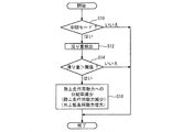
- It is a flowchart which shows the general
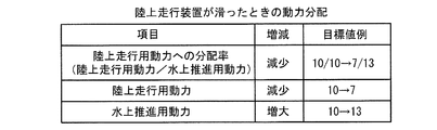
- 5 is a table showing an example of power distribution according to the program of FIG. 4;
- It is a flowchart which shows the general
- FIG. 7 is a table showing an example of power distribution according to the program of FIG.
- FIG. 6 It is a block diagram showing a schematic structure of an amphibian according to some embodiments. It is a flowchart which shows the general
- FIG. 10 is a table showing an example of power distribution according to the program of FIG. 9; It is a flowchart which shows the general
- FIG. 1 is a block diagram showing a schematic configuration of an amphibian according to some embodiments.
- the amphibious vehicle includes an engine 10, at least one land traveling device 12, at least one over-the-water propulsion device 14, a power distribution device 16, a slip amount detection device 18, and a control device 20.
- the engine 10 can output power for moving an amphibian, and is made of, for example, a diesel engine.
- the land traveling device 12 is configured to move the amphibian by causing at least a part of the power output from the engine 10 to act on the ground.
- the marine propulsion device 14 is configured to move the amphibian by causing at least a portion of the power output from the engine 10 to act on the water.
- FIG. 2 is a side view schematically showing an amphibious vehicle according to some embodiments, and the land traveling device 12 is composed of a crawler belt (infinite track, cataply) 22, and the water propulsion device 14 is an internal water channel 24.
- the water jet 28 includes a propeller 26 disposed at the FIG. 3 is a side view schematically illustrating an amphibian according to some other embodiments, where the land vehicle 12 comprises a tire 30 and the marine propulsion device 14 comprises a propeller 32.
- the power distribution device 16 distributes the power output from the engine 10 to the power distributed to the land traveling device 12 (power for land traveling) and the power supplied to the water propulsion device 14 (power for water propulsion). Is configured.
- the power distribution device 16 is, for example, an electronically controlled torque distribution device, and can actively adjust the distribution ratio of power to the power for land use.
- the slippage detection device 18 is configured to detect the slippage of the ground traveling device 12 with respect to the ground.
- the control device 20 is configured by, for example, a computer including a CPU (central processing unit), a memory, and an external storage device.
- the slip amount detected by the slip amount detection device 18 is input to the control device 20, and the control device 20 outputs a control signal to the power distribution device 16 based on the input slip amount.
- the amphibian's mode of operation has three modes of operation, a land mode, an intermediate mode, and a surface mode, and the amphibian has one of three modes of operation selected. Operate according to the mode.
- the land mode is a mode for traveling on land, and when the land mode is selected, power is supplied only to the land traveling device 12 and power is not supplied to the marine propulsion device 14.
- the water mode is a mode for sailing on water, and when the water mode is selected, power is supplied only to the water propulsion device 14 and power is not supplied to the land traveling device 12.
- the intermediate mode is a mode for landing on water from the water and a mode for launching water on land, and an amphibious vehicle is on the water in the range of water depth where the ground traveling device 12 can be grounded. When selected. When the intermediate mode is selected, power is supplied to both the land traveling device 12 and the water propulsion device 14 so that the land traveling device 12 causes the water bottom to operate, while the water propulsion device 14 causes the water to operate. This will move the amphibious vehicle.
- Selection of the operation mode may be performed automatically or manually.
- the height (water depth) of the amphibious vehicle from the ground is measured by a distance measuring device such as a sonar, and selection is performed according to the measurement result, or the land traveling device 12 by a load detection device
- the load applied to the axle of the vehicle may be measured, and selection may be made according to the measurement result.
- the controller 20 controls the land traveling device 12 and the water propulsion device 14 to be landed from the water to land, respectively, when the land traveling power and the water propulsion power are respectively supplied, that is, when the intermediate mode is selected.
- the power distribution device 16 is controlled to reduce the power for land traveling.
- the controller 20 reduces the distribution ratio of power to the land power when the slip amount detected by the slip amount detection device 18 exceeds the threshold. Is configured as.
- FIG. 4 is a flowchart showing a schematic flow of a program executed by the control device 20 of an amphibian according to some embodiments.
- the controller 20 repeatedly executes the program of FIG. 4 periodically or irregularly.
- the control device 20 confirms whether or not the intermediate mode is being executed (operation mode check step S10). That is, it is checked whether the land traveling power and the water propulsion power are respectively supplied to the land traveling device 12 and the water propulsion device 14.
- the control device 20 detects the amount of slip of the land traveling device 12 with respect to the ground via the slip amount detection device 18 (slip amount detection step S12). Then, the control device 20 compares the detected slip amount with a preset threshold value (slip amount determination step S14). As a result of comparison of the slip amount determination step S14, when the slip amount of the land traveling device 12 exceeds the preset threshold value, the control device 20 controls the power distribution device 16 to make the land traveling power. The power distribution rate of the vehicle is reduced (the power distribution rate decreasing step S16 for land traveling). In some embodiments, only the land-running power is reduced and the water-borne propulsion power is kept unchanged. After the land traveling power distribution factor decreasing step S16, or if the check result of the operation mode check step S10 or the comparison result of the slip amount determination step S14 is negative, the flow of the program is once ended.
- FIG. 5 is a table showing an example of power distribution according to the program of FIG. 4 when the slippage exceeds the threshold.
- the slippage amount of the land traveling device 12 exceeds the threshold value, the land traveling power distributed to the land traveling device 12 is reduced, so that the wasteful consumption of the power output by the engine 10 Is suppressed. And since the power for land traveling is reduced, the slip of the land traveling device 12 is eliminated, and the power of the land traveling device 12 is effectively applied to the ground. As a result, the amphibious vehicle can travel by effectively utilizing the power output from the engine regardless of the condition of the bottom of the water, and has a high landing capability.
- FIG. 6 is a flowchart showing a schematic flow of a program executed by the control device 20 for an amphibian according to some embodiments
- FIG. 7 shows an example of power distribution according to the program of FIG. It is a table.
- the program of FIG. 6 is different from the program of FIG. 4 in that the power for propulsion on water is increased in the power distribution factor decreasing step S18 for land traveling. According to this configuration, it is possible to compensate for the reduction in the power for land propulsion by increasing the power for propulsion on the water (target value 10 ⁇ 13) when the land traveling device 12 slips against the ground (target value 10 ⁇ 13). The landing ability can be further enhanced.
- FIG. 8 is a block diagram showing a schematic configuration of an amphibian according to some embodiments.
- the amphibious vehicle shown in FIG. 8 has, as a land traveling device, a first land traveling device 12a disposed on the right side of the amphibious vehicle and a second land traveling device 12b disposed on the left side of the amphibious vehicle. There is. And, the amphibious vehicle has a first on-water propulsion device 14a disposed on the right side of the amphibious vehicle and a second on-water propulsion device 14b disposed on the left side of the amphibious vehicle as a water propulsion device. .
- the power distribution device 16 distributes the output of the engine to the power for land traveling and the power for over the water traveling, and the first land power for traveling traveling traveling the power for land traveling to the first land traveling apparatus 12a.
- the left and right power distribution unit for land traveling (gearshift steering device) 16b for distributing to the second land traveling power distributed to the second land traveling device 12b, and the power for propulsion on water are distributed to the first water propulsion device 14a And a second over-the-water propulsion power distributed to the second over-the-water propulsion device 14b.
- the slippage detection device 18 includes a first rotation speed sensor 18a, a second rotation speed sensor 18b, a vehicle speed sensor 18c, and a slippage calculation device 18d.
- the first rotation number sensor 18a can detect the rotation number (rotational speed V1) of the first land traveling device 12a
- the second rotation number sensor 18b can set the rotation number (rotational speed V2) of the second land traveling device 12b.
- the vehicle speed sensor 18c can detect the actual speed (vehicle speed V0) of the amphibian.
- a gyro a laser Doppler measurement meter, a pitot tube, an acceleration sensor, a GPS (global positioning system), or the like can be used.
- the slippage computing device 18 d is configured by a computer including, for example, a CPU, a memory, and an external storage device, but may be provided integrally with the control device 20.
- the slippage computing device 18d is a first land based on the ground based on the rotation speed V1 of the first land traveling device 12a detected by the first rotation speed sensor 18a and the vehicle speed V0 of the amphibious vehicle detected by the vehicle speed sensor 18c.
- the slippage computing device 18d is driven by the second vehicle speed V2 detected by the second rotation speed sensor 18b and the vehicle speed V0 of the amphibious vehicle detected by the vehicle speed sensor 18c. 2
- the slip amount S1 and the slip amount S2 calculated by the slip amount calculating device 18d are input to the control device 20.
- the control device 20 controls the distribution ratio of the land / water distribution unit 16a of the power distribution device 16, the land traveling power left / right distribution unit 16b, and the on-the-water propulsion power left / right distribution unit 16c based on the slip amount S1 and the slip amount S2. Do.
- the control device 20 performs the first land traveling to the first land traveling device 12a, the second land traveling device 12b, the first water propulsion device 14a, and the second water propulsion device 14b in order to land from the water to land.
- Amount of slip S1 of the first land traveling apparatus 12a detected by the slip amount detection device 18 when each of the second motive power, the second land propulsion power, the first over-water propulsion power, and the second over-water propulsion power is supplied.
- the slippage amount S2 of the second land traveling device 12b exceeds the threshold value, the corresponding first land traveling power or the second land traveling power is reduced.
- the control device 20 controls the land division unit 16a to transmit power to the land traveling device.
- the ratio of the land traveling power supplied to the slipping land traveling device is reduced and the non-slip land traveling device is supplied. Increase the ratio of land-running power.
- the control device 20 controls the land division unit 16a to transmit power to the land traveling device.
- control device 20 can control the land traveling power left / right distribution unit 16b so that the land traveling power supplied to the larger slip amount becomes smaller, and the slip amounts S1 and S2 are substantially
- the ratio of the first land traveling power supplied to the first land traveling apparatus 12a and the second land traveling power supplied to the second land traveling apparatus 12b may be equal to each other.
- the control device 20 is configured to adjust the ratio of the first water propulsion power to the second water propulsion power based on the ratio of the first land traveling power to the second land traveling power. .
- FIG. 9 is a flow chart schematically showing the flow of a program that the control device 20 of the amphibian of FIG. 8 repeatedly executes at regular or irregular intervals.
- the rotational speeds V1 and V2 are detected (rotational speed detection step S20), and the vehicle speed V0 is detected (vehicle speed detection step S22).
- the slip amount S1 is calculated based on the rotation speed V1 and the vehicle speed V0
- the slip amount S2 is calculated based on the rotation speed V2 and the vehicle speed V0 (slip amount calculation step S24).
- the calculated slippage amount S1 and slippage amount S2 are compared with a preset threshold value (slippage amount determination step S26).
- the slip amount S1 and the slip amount S2 exceeds the threshold value, distribution of power to the power for land use is performed so that the slip of the land traveling device is suppressed based on the slip amount S1 and the slip amount S2.
- the power for land traveling is reduced while the power for propulsion on the water is kept unchanged.
- the second land traveling power is changed (land traveling power left / right distribution ratio changing step S30).
- the power for propulsion / the power for second waterborne propulsion is changed (a power for displacing the waterborne propulsion power left / right distribution ratio changing step S32).
- FIG. 10 is a table showing an example of power distribution according to the program of FIG. 9 when the slip amount S1 of the first land traveling apparatus 12a exceeds the threshold.
- the left / right distribution ratio of the land traveling power is changed (target value 5/5 ⁇ 3/4) and the first land traveling power is decreased (target value 5 ⁇ 3), and the left and right power of the water propulsion power is changed
- the distribution rate is changed (target value 5/5 ⁇ 6/4), and the first water propulsion power is increased (target value 5 ⁇ 6).
- the power for the second land traveling also decreases with the decrease of the distribution rate to the power for land traveling (target value 5 ⁇ 3).
- the land traveling is slipped by reducing the power for land traveling supplied to the land traveling device that is slipping among the first land traveling device 12a and the second land traveling device 12b.
- the slip of the device can be eliminated.
- the reduction in the power for land traveling supplied to the non-slip land traveling apparatus is suppressed, it is possible to suppress the reduction in the power for land traveling as a whole. As a result, according to this configuration, the landing ability can be further enhanced.
- the first water propulsion power is based on the ratio of the first land traveling power to the second land traveling power.
- the ratio of the second over-the-water propulsion power By adjusting the ratio of the second over-the-water propulsion power, the turning of the amphibian can be suppressed. That is, by increasing the power for propulsion on the water supplied to the water propulsion apparatus on the sliding side, the turning of the amphibian can be suppressed, and the amphibian can proceed stably. As a result, according to this configuration, the landing ability can be further enhanced.
- FIG. 11 is a flowchart showing a schematic flow of a program executed by the control device 20 for an amphibious vehicle according to some embodiments
- FIG. 12 shows an example of power distribution according to the program of FIG. It is a table.
- the program of FIG. 11 is different from the program of FIG. 9 in that the power for propulsion on the water is increased in the power distribution factor decreasing step S34 for land traveling. According to this configuration, when the first land traveling device 12a or the second land traveling device 12b slips with respect to the ground, the power for propulsion on the water is increased (target value 10 ⁇ 13). It can compensate for the decrease and can further enhance the landing ability.
- FIG. 13 is a block diagram showing a schematic configuration of an amphibian according to some embodiments.
- the amphibian of FIG. 13 is different from the amphibian of FIG. 8 in that the amphibian of FIG. 13 further includes a yaw angle detection device 34 capable of detecting the yaw angle (turning angle) of the amphibian.
- the control device 20 substitutes the ratio of the first land traveling power to the second land traveling power, and based on the yaw angle of the amphibious vehicle detected by the yaw angle detection device 34, the first water propulsion It is configured to adjust the ratio between the power and the second water propulsion power. That is, the control device 20 adjusts the ratio of the first water propulsion power to the second water propulsion power so as to cancel the yaw angle caused by the imbalance between the first land power and the second land power. Is configured as.
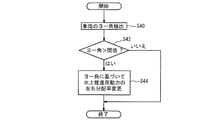
- FIG. 14 schematically shows the flow of a program for adjusting the ratio of the first over-the-water propulsion power and the second over-the-water propulsion power based on the yaw angle.
- the program of FIG. 14 is executed instead of the water propulsion power left / right distribution ratio changing step S32 of the programs of FIGS. 9 and 11.
- the yaw angle of the amphibian is detected (Yaw angle detection step S40).
- the detected yaw angle is compared with a preset threshold (yaw angle determination step S42), and if the yaw angle exceeds the threshold, the first water propulsion power and the second water propulsion are based on the yaw angle.
- the ratio of the power is changed (power-over-water motive power left / right distribution ratio changing step S44).
- the on-the-water propulsion power left / right distribution ratio change step S44 ends, or if the determination result of the yaw angle determination step S42 is negative, the flow of the program ends.
- the ratio of the first on-water propulsion power to the second on-water propulsion power based on the yaw angle (turning angle)
- the turning of the amphibian can be suppressed by adjusting the ratio of the first on-water propulsion power and the second on-water propulsion power so as to cancel the turning.
- the landing ability can be further enhanced.
- the vehicle speed sensor 18c included in the slip amount detection device 18 in FIG. 8 or 13 may be omitted. In this case, based on the changes in the rotational speeds V1 and V2 detected by the first rotation speed sensor 18a and the second rotation speed sensor 18b, respectively, the slip amounts of the first land traveling device 12a and the second land traveling device 12b are It can be detected.
- the power distribution rate to the land traveling power is restored after the predetermined time has elapsed or after the predetermined distance traveled. It is also good. Furthermore, in some embodiments, after changing the ratio of the first land traveling power to the second land traveling power, the first land traveling power and the second land traveling after a predetermined time has elapsed or after a predetermined distance traveled. The power ratio may be returned to the original. If the predetermined time has elapsed or the predetermined distance travels, it is conceivable that the condition of the water bottom changes, and the land traveling device 12 can not slip even if the land traveling power is large. For this reason, by returning the distribution ratio of the power to the power for land traveling and the ratio of the power for the first land travel to the power for the second land travel, the engine performance can be more effectively utilized to further improve the landing performance. It can be further enhanced.
- the present invention is not limited to the above-described embodiment, but includes the embodiments in which the above-described embodiment is modified, and the embodiments in which the above-described embodiment is appropriately combined.
- the control device 20 reduces the output of the engine 10 without changing the distribution ratio of the power to the land traveling power. Good.
- the slippage amount of the land traveling device 12 exceeds the threshold value, the land traveling power distributed to the land traveling device 12 is reduced, so wasteful consumption of the power output by the engine 10 is suppressed. Ru.
- the power for land traveling is reduced, the slip of the land traveling device 12 is eliminated, and the power of the land traveling device 12 is effectively applied to the ground.
- the amphibious vehicle can travel by effectively utilizing the power output from the engine regardless of the condition of the bottom of the water, and has a high landing capability.
Landscapes
- Engineering & Computer Science (AREA)
- Chemical & Material Sciences (AREA)
- Combustion & Propulsion (AREA)
- Mechanical Engineering (AREA)
- Transportation (AREA)
- Ocean & Marine Engineering (AREA)
- Electric Propulsion And Braking For Vehicles (AREA)
- Hybrid Electric Vehicles (AREA)
Abstract
水陸両用車は、機関と、陸上走行装置と、水上推進装置と、機関から出力された動力を陸上走行用動力と水上推進用動力とに分配するように構成された動力分配装置と、地面に対する陸上走行装置の滑り量を検出するように構成された滑り量検出装置と、滑り量検出装置によって検出された滑り量に基づいて、陸上走行用動力及び水上推進用動力のうち少なくとも陸上走行用動力を調整するように構成された制御装置とを備え、制御装置は、上陸するために陸上走行装置及び水上推進装置に陸上走行用動力及び水上推進用動力がそれぞれ供給されているときに滑り量が閾値を超えた場合、陸上走行用動力を減少させるように構成されている。
Description
本開示は、水陸両用車及びその制御方法に関する。
水陸両用車は、例えば、機関と、装軌やタイヤからなる陸上走行装置と、ウォータジェットやプロペラからなる水上走行装置と、機関によって出力された動力を陸上走行装置と水上走行装置とに分配する動力分配装置とを備える。
そして、特許文献1が開示する水陸両用車は、エンジン出力分配器(動力分配装置)を制御する車両制御装置と、車両速度センサと、エンジン回転トルクセンサとを備える。この水陸両用車は、陸上モード、水上モード及び中間モードの3つのモードで運転可能であり、中間モードでは、機関の動力が陸上走行装置と水上走行装置とに分配される。そして、中間モードにおいて、車両速度とエンジン回転トルクに基づいて陸上走行装置の滑りが検出されると、機関の出力が増大される。これにより、水上推進装置の動力が増大され、滑りによって減少した車両速度が増加して安定する。
水陸両用車の上陸地点としては、陸から水中までなだらかな砂地が続いている砂浜が適している。このような砂浜へ上陸する場合、陸上走行装置と水上走行装置の両方を作動させたときに、陸上走行装置が水底の砂地に対して滑らず、陸上走行装置に供給された動力を砂地に対して無駄なく有効に作用させることができる。このため、水陸両用車は機関の動力を有効に活用して砂浜へ容易に上陸することができる。
これに対し、上陸地点として、水底に岩礁等が存在するような場所を選択した場合、陸上走行装置が岩礁等に対して滑ることがある。陸上走行装置が滑ると、陸上走行装置に供給される動力が無駄になるばかりでなく、陸上走行装置に供給された動力を水底に有効に作用させることができず、上陸が困難になることがある。
そこで本発明の少なくとも一実施形態は、水底の状況にかかわらずに陸上走行装置の滑りを抑制して機関が出力した動力を有効に活用することにより、高い上陸能力を有する水陸両用車及びその制御方法を提供することを目的とする。
本発明の少なくとも一実施形態によれば、
機関と、
少なくとも1つの陸上走行装置と、
少なくとも1つの水上推進装置と、
前記機関から出力された動力を前記少なくとも1つの陸上走行装置に供給される陸上走行用動力と前記少なくとも1つの水上推進装置に供給される水上推進用動力とに分配するように構成された動力分配装置と、
地面に対する前記少なくとも1つの陸上走行装置の滑り量を検出するように構成された滑り量検出装置と、
前記滑り量検出装置によって検出された滑り量に基づいて、前記陸上走行用動力及び前記水上推進用動力のうち少なくとも前記陸上走行用動力を調整するように構成された制御装置とを備え、
前記制御装置は、水上から陸上へ上陸するために前記少なくとも1つの陸上走行装置及び前記少なくとも1つの水上推進装置に前記陸上走行用動力及び前記水上推進用動力がそれぞれ供給されているときに前記滑り量検出装置によって検出された滑り量が閾値を超えた場合、前記陸上走行用動力を減少させるように構成されている
ことを特徴とする水陸両用車が提供される。
機関と、
少なくとも1つの陸上走行装置と、
少なくとも1つの水上推進装置と、
前記機関から出力された動力を前記少なくとも1つの陸上走行装置に供給される陸上走行用動力と前記少なくとも1つの水上推進装置に供給される水上推進用動力とに分配するように構成された動力分配装置と、
地面に対する前記少なくとも1つの陸上走行装置の滑り量を検出するように構成された滑り量検出装置と、
前記滑り量検出装置によって検出された滑り量に基づいて、前記陸上走行用動力及び前記水上推進用動力のうち少なくとも前記陸上走行用動力を調整するように構成された制御装置とを備え、
前記制御装置は、水上から陸上へ上陸するために前記少なくとも1つの陸上走行装置及び前記少なくとも1つの水上推進装置に前記陸上走行用動力及び前記水上推進用動力がそれぞれ供給されているときに前記滑り量検出装置によって検出された滑り量が閾値を超えた場合、前記陸上走行用動力を減少させるように構成されている
ことを特徴とする水陸両用車が提供される。
この構成によれば、陸上走行装置の滑り量が閾値を超えた場合、陸上走行装置に分配される陸上走行用動力が減少させられるので、機関によって出力された動力の無駄な消費が抑制される。そして、陸上走行用動力が減少させられるので、陸上走行装置の滑りが解消され、陸上走行装置の動力が地面に対し有効に作用させられる。この結果、水陸両用車は、水底の状況にかかわらずに機関が出力した動力を有効に活用して進行することができ、高い上陸能力を有する。
幾つかの実施形態では、前記制御装置は、前記滑り量検出装置によって検出された滑り量が閾値を超えた場合、前記水上推進用動力を増大させるように構成されている。
この構成によれば、水上推進用動力を増大させることによって、陸上推進用動力の減少を補償することができ、より一層上陸能力を高めることができる。
幾つかの実施形態では、前記少なくとも1つの陸上走行装置は、前記水陸両用車の右側に配置された第1陸上走行装置及び前記水陸両用車の左側に配置された第2陸上走行装置からなり、
前記少なくとも1つの水上推進装置は、前記水陸両用車の右側に配置された第1水上推進装置及び前記水陸両用車の左側に配置された第2水上推進装置からなり、
前記動力分配装置は、前記動力を、前記第1陸上走行装置に供給される第1陸上走行用動力と第2陸上走行装置に供給される第2陸上走行用動力と前記第1水上推進装置に供給される第1水上推進用動力と前記第2水上推進装置に供給される第2水上推進用動力とに分配するように構成され、
前記滑り量検出装置は、前記第1陸上走行装置及び第2陸上走行装置の各々の地面に対する滑り量を検出するように構成され、
前記制御装置は、水上から陸上へ上陸するために前記第1陸上走行装置、前記第2陸上走行装置、前記第1水上推進装置及び前記第2水上推進装置に前記第1陸上走行用動力、前記第2陸上走行用動力、前記第1水上推進用動力及び前記第2水上推進用動力がそれぞれ供給されているときに前記滑り量検出装置によって検出された前記第1陸上走行装置又は前記第2陸上走行装置の滑り量が閾値を超えた場合、対応する前記第1陸上走行用動力又は前記第2陸上走行用動力を減少させるように構成されている。
前記少なくとも1つの水上推進装置は、前記水陸両用車の右側に配置された第1水上推進装置及び前記水陸両用車の左側に配置された第2水上推進装置からなり、
前記動力分配装置は、前記動力を、前記第1陸上走行装置に供給される第1陸上走行用動力と第2陸上走行装置に供給される第2陸上走行用動力と前記第1水上推進装置に供給される第1水上推進用動力と前記第2水上推進装置に供給される第2水上推進用動力とに分配するように構成され、
前記滑り量検出装置は、前記第1陸上走行装置及び第2陸上走行装置の各々の地面に対する滑り量を検出するように構成され、
前記制御装置は、水上から陸上へ上陸するために前記第1陸上走行装置、前記第2陸上走行装置、前記第1水上推進装置及び前記第2水上推進装置に前記第1陸上走行用動力、前記第2陸上走行用動力、前記第1水上推進用動力及び前記第2水上推進用動力がそれぞれ供給されているときに前記滑り量検出装置によって検出された前記第1陸上走行装置又は前記第2陸上走行装置の滑り量が閾値を超えた場合、対応する前記第1陸上走行用動力又は前記第2陸上走行用動力を減少させるように構成されている。
この構成では、第1及び第2陸上走行装置のうち滑っている陸上走行装置に供給される陸上走行用動力を減少させることによって、滑っている陸上走行装置の滑りを解消することができる。一方、滑っていない陸上走行装置に供給される陸上走行用動力の減少は抑制されるので、全体として、陸上走行用動力の減少を抑制することができる。この結果として、この構成によれば、より一層上陸能力を高めることができる。
幾つかの実施形態では、前記制御装置は、前記第1陸上走行用動力と前記第2陸上走行用動力の比率に基づいて、前記第1水上推進用動力と前記第2水上推進用動力の比率を調整するように構成されている。
この構成では、第1陸上走行用動力と第2陸上走行用動力の比率が変更されても、第1陸上走行用動力と第2陸上走行用動力の比率に基づいて第1水上推進用動力と前記第2水上推進用動力の比率を調整することによって、水陸両用車の旋回を抑制することができる。即ち、陸上走行装置が滑っている側の水上推進装置に供給される水上推進用動力を増大することにより、水陸両用車の旋回を抑制することができ、水陸両用車が安定して進行することができる。この結果として、この構成によれば、より一層上陸能力を高めることができる。
幾つかの実施形態では、水陸両用車は前記水陸両用車のヨー角を検出するように構成されたヨー角検出装置を更に備え、
前記制御装置は、前記ヨー角検出装置によって検出されたヨー角に基づいて、前記第1水上推進用動力と前記第2水上推進用動力の比率を調整するように構成されている。
前記制御装置は、前記ヨー角検出装置によって検出されたヨー角に基づいて、前記第1水上推進用動力と前記第2水上推進用動力の比率を調整するように構成されている。
この構成では、第1陸上走行用動力と第2陸上走行用動力の比率が変更されても、ヨー角に基づいて第1水上推進用動力と前記第2水上推進用動力の比率を調整することによって、水陸両用車の旋回を抑制することができる。即ち、旋回を打ち消すように第1水上推進用動力と第2水上推進用動力の比率を調整することによって、水陸両用車の旋回を抑制することができる。この結果として、この構成によれば、より一層上陸能力を高めることができる。
幾つかの実施形態では、前記滑り量検出装置は、前記少なくとも1つの陸上走行装置の回転数又はトルクを測定するためのセンサを有する。
幾つかの実施形態では、前記滑り量検出装置は、前記水陸両用車の速度を測定するための車速センサを更に有する。
幾つかの実施形態では、前記陸上走行装置は無限軌道を有し、
前記水上推進装置はウォータジェットを有する。
前記水上推進装置はウォータジェットを有する。
本発明の少なくとも一実施形態によれば、機関と、少なくとも1つの陸上走行装置と、少なくとも1つの水上推進装置とを備える水陸両用車の制御方法において、
水上から陸上へ上陸するために、前記機関から出力された動力を前記少なくとも1つの陸上走行装置に供給される陸上走行用動力と前記少なくとも1つの水上推進装置に供給される水上推進用動力とに分配する分配工程と、
地面に対する前記少なくとも1つの陸上走行装置の滑り量を検出する滑り量検出工程と、
前記少なくとも1つの陸上走行装置及び前記少なくとも1つの水上推進装置に前記陸上走行用動力及び前記水上推進用動力がそれぞれ供給されているときに前記滑り量検出工程によって検出された滑り量が閾値を超えた場合、前記陸上走行用動力を減少させる陸上走行用動力制御工程と
を備えることを特徴とする水陸両用車の制御方法が提供される。
水上から陸上へ上陸するために、前記機関から出力された動力を前記少なくとも1つの陸上走行装置に供給される陸上走行用動力と前記少なくとも1つの水上推進装置に供給される水上推進用動力とに分配する分配工程と、
地面に対する前記少なくとも1つの陸上走行装置の滑り量を検出する滑り量検出工程と、
前記少なくとも1つの陸上走行装置及び前記少なくとも1つの水上推進装置に前記陸上走行用動力及び前記水上推進用動力がそれぞれ供給されているときに前記滑り量検出工程によって検出された滑り量が閾値を超えた場合、前記陸上走行用動力を減少させる陸上走行用動力制御工程と
を備えることを特徴とする水陸両用車の制御方法が提供される。
この構成によれば、陸上走行装置の滑り量が閾値を超えた場合、陸上走行装置に分配される陸上走行用動力が減少させられるので、機関によって出力された動力の無駄な消費が抑制される。そして、陸上走行用動力が減少させられるので、陸上走行装置の滑りが解消され、陸上走行装置の動力が地面に対し有効に作用させられる。この結果、水陸両用車は、水底の状況にかかわらずに機関が出力した動力を有効に活用して進行することができ、高い上陸能力を得られる。
本発明の少なくとも一実施形態によれば、水底の状況にかかわらずに陸上走行装置の滑りを抑制して機関が出力した動力を有効に活用することにより、高い上陸能力を有する水陸両用車及びその制御方法が提供される。
以下、添付図面を参照して、本発明の実施形態について説明する。ただし、この実施形態に記載されている又は図面に示されている構成部品の寸法、材質、形状及びその相対的配置等は、本発明の範囲をこれに限定する趣旨ではなく、単なる説明例にすぎない。
図1は、幾つかの実施形態に係る水陸両用車の概略的な構成を示すブロック図である。
水陸両用車は、機関10と、少なくとも1つの陸上走行装置12と、少なくとも1つの水上推進装置14と、動力分配装置16と、滑り量検出装置18と、制御装置20とを備える。
水陸両用車は、機関10と、少なくとも1つの陸上走行装置12と、少なくとも1つの水上推進装置14と、動力分配装置16と、滑り量検出装置18と、制御装置20とを備える。
機関10は、水陸両用車が移動するための動力を出力可能であり、例えばディーゼルエンジンからなる。
陸上走行装置12は、機関10が出力した動力の少なくとも一部を地面に対し作用させることにより、水陸両用車を移動させるように構成されている。
水上推進装置14は、機関10が出力した動力の少なくとも一部を水に対し作用させることにより、水陸両用車を移動させるように構成されている。
陸上走行装置12は、機関10が出力した動力の少なくとも一部を地面に対し作用させることにより、水陸両用車を移動させるように構成されている。
水上推進装置14は、機関10が出力した動力の少なくとも一部を水に対し作用させることにより、水陸両用車を移動させるように構成されている。
ここで図2は、幾つかの実施形態に係る水陸両用車を概略的に示す側面図であり、陸上走行装置12は履帯(無限軌道、カタピラ)22からなり、水上推進装置14は内部水路24に配置されたプロペラ26を含むウォータジェット28からなる。
図3は、他の幾つかの実施形態の水陸両用車を概略的に示す側面図であり、陸上走行装置12はタイヤ30からなり、水上推進装置14はプロペラ32からなる。
図3は、他の幾つかの実施形態の水陸両用車を概略的に示す側面図であり、陸上走行装置12はタイヤ30からなり、水上推進装置14はプロペラ32からなる。
動力分配装置16は、機関10が出力した動力を、陸上走行装置12に分配される動力(陸上走行用動力)と水上推進装置14に供給される動力(水上推進用動力)とに分配するように構成されている。動力分配装置16は、例えば電子制御式のトルク分配装置からなり、陸上走行用動力への動力の分配率を能動的に調整することができる。
滑り量検出装置18は、地面に対する陸上走行装置12の滑り量を検出するように構成されている。
制御装置20は、例えば、CPU(中央演算処理装置)、メモリ及び外部記憶装置からなるコンピュータによって構成される。制御装置20には、滑り量検出装置18によって検出された滑り量が入力され、制御装置20は、入力された滑り量に基づいて、動力分配装置16に制御信号を出力する。動力分配装置16は、制御装置20から受け取った制御信号に基づいて、陸上走行用動力への動力の分配率(=陸上走行用動力/水上推進用動力)を調整可能である。つまり、制御装置20は、入力された滑り量に基づいて動力分配装置16を制御することにより、陸上走行用動力及び水上推進用動力のうち少なくとも陸上走行用動力を調整するように構成されている。
制御装置20は、例えば、CPU(中央演算処理装置)、メモリ及び外部記憶装置からなるコンピュータによって構成される。制御装置20には、滑り量検出装置18によって検出された滑り量が入力され、制御装置20は、入力された滑り量に基づいて、動力分配装置16に制御信号を出力する。動力分配装置16は、制御装置20から受け取った制御信号に基づいて、陸上走行用動力への動力の分配率(=陸上走行用動力/水上推進用動力)を調整可能である。つまり、制御装置20は、入力された滑り量に基づいて動力分配装置16を制御することにより、陸上走行用動力及び水上推進用動力のうち少なくとも陸上走行用動力を調整するように構成されている。
幾つかの実施形態では、水陸両用車の動作モードには、陸上モード、中間モード及び水上モードの3つの動作モードがあり、水陸両用車は、3つの動作モードの中から選択された一つの動作モードに従って作動する。
陸上モードは、陸上を走行するためのモードであり、陸上モードが選択されているときには、陸上走行装置12のみに動力が供給され、水上推進装置14には動力が供給されない。
陸上モードは、陸上を走行するためのモードであり、陸上モードが選択されているときには、陸上走行装置12のみに動力が供給され、水上推進装置14には動力が供給されない。
水上モードは、水上を航行するためのモードであり、水上モードが選択されているときには、水上推進装置14のみに動力が供給され、陸上走行装置12には動力が供給されない。
中間モードは、水上から陸上に上陸するためのモードであるとともに、陸上から水上に進水するためのモードであり、陸上走行装置12が接地可能な水深の範囲で、水陸両用車が水上にあるときに選択される。中間モードが選択されているときには、陸上走行装置12及び水上推進装置14の両方に動力が供給され、陸上走行装置12が水底に動力を作用させる一方、水上推進装置14が水に動力を作用させ、これにより水陸両用車が移動する。
中間モードは、水上から陸上に上陸するためのモードであるとともに、陸上から水上に進水するためのモードであり、陸上走行装置12が接地可能な水深の範囲で、水陸両用車が水上にあるときに選択される。中間モードが選択されているときには、陸上走行装置12及び水上推進装置14の両方に動力が供給され、陸上走行装置12が水底に動力を作用させる一方、水上推進装置14が水に動力を作用させ、これにより水陸両用車が移動する。
動作モードの選択は、自動で行ってもよく、手動で行ってもよい。動作モードを自動で選択する場合、ソナー等の測距装置によって地面からの水陸両用車の高さ(水深)を測定し、測定結果に応じて選択を行ったり、荷重検出装置によって陸上走行装置12の車軸にかかる荷重を測定し、測定結果に応じて選択を行ってもよい。
制御装置20は、水上から陸上へ上陸するために陸上走行装置12及び水上推進装置14に陸上走行用動力及び水上推進用動力がそれぞれ供給されているとき、即ち中間モードが選択されているときに、滑り量検出装置18によって検出された滑り量が閾値を超えた場合、動力分配装置16を制御して、陸上走行用動力を減少させるように構成されている。換言すれば、制御装置20は、中間モードが選択されているときに、滑り量検出装置18によって検出された滑り量が閾値を超えた場合、陸上走行用動力への動力の分配率を減少させるように構成されている。
以下、水陸両用車の制御方法について説明する。図4は、幾つかの実施形態に係る水陸両用車の制御装置20が実行するプログラムの概略的な流れを示すフローチャートである。幾つかの実施形態では、制御装置20は、図4のプログラムを定期又は不定期にて繰り返し実行する。
図4に示したように、制御装置20は、中間モードが実行されているか否かを確認する(動作モード確認工程S10)。すなわち、陸上走行装置12及び水上推進装置14に陸上走行用動力及び水上推進用動力がそれぞれ供給されているか否かを確認する。
図4に示したように、制御装置20は、中間モードが実行されているか否かを確認する(動作モード確認工程S10)。すなわち、陸上走行装置12及び水上推進装置14に陸上走行用動力及び水上推進用動力がそれぞれ供給されているか否かを確認する。
中間モードが実行されている場合、制御装置20は、滑り量検出装置18を介して、地面に対する陸上走行装置12の滑り量を検出する(滑り量検出工程S12)。そして、制御装置20は、検出した滑り量と予め設定された閾値とを比較する(滑り量判定工程S14)。
滑り量判定工程S14の比較の結果、陸上走行装置12の滑り量が、予め設定された閾値を超えている場合、制御装置20は、動力分配装置16を制御することにより、陸上走行用動力への動力の分配率を減少させる(陸上走行用動力分配率減少工程S16)。幾つかの実施形態では、陸上走行用動力のみを減少させ、水上推進用動力は不変に保たれる。
陸上走行用動力分配率減少工程S16の後、或いは、動作モード確認工程S10の確認結果や滑り量判定工程S14の比較結果が否の場合、プログラムのフローは一旦終了する。
滑り量判定工程S14の比較の結果、陸上走行装置12の滑り量が、予め設定された閾値を超えている場合、制御装置20は、動力分配装置16を制御することにより、陸上走行用動力への動力の分配率を減少させる(陸上走行用動力分配率減少工程S16)。幾つかの実施形態では、陸上走行用動力のみを減少させ、水上推進用動力は不変に保たれる。
陸上走行用動力分配率減少工程S16の後、或いは、動作モード確認工程S10の確認結果や滑り量判定工程S14の比較結果が否の場合、プログラムのフローは一旦終了する。
図5は、滑り量が閾値を超えた場合における、図4のプログラムに従った動力分配の一例を示す表である。図5に示したように、図4のプログラムによれば、滑り量が閾値を超えた場合、陸上走行用動力への動力の分配率(=陸上走行用動力/水上推進用動力)が減少させられており(目標値10/10→7/10)、陸上走行用動力のみが減少させられ(目標値10→7)、水上推進用動力は不変(目標値10→10)に保たれている。
上述した構成によれば、陸上走行装置12の滑り量が閾値を超えた場合、陸上走行装置12に分配される陸上走行用動力が減少させられるので、機関10によって出力された動力の無駄な消費が抑制される。そして、陸上走行用動力が減少させられるので、陸上走行装置12の滑りが解消され、陸上走行装置12の動力が地面に対し有効に作用させられる。この結果、水陸両用車は、水底の状況にかかわらずに機関が出力した動力を有効に活用して進行することができ、高い上陸能力を有する。
図6は、幾つかの実施形態に係る水陸両用車の制御装置20が実行するプログラムの概略的な流れを示すフローチャートであり、図7は、図6のプログラムに従った動力分配の一例を示す表である。
図6のプログラムは、陸上走行用動力分配率減少工程S18において、水上推進用動力を増大させる点において、図4のプログラムとは異なっている。この構成によれば、陸上走行装置12が地面に対して滑った場合に水上推進用動力を増大させることによって(目標値10→13)、陸上推進用動力の減少を補償することができ、より一層上陸能力を高めることができる。
図6のプログラムは、陸上走行用動力分配率減少工程S18において、水上推進用動力を増大させる点において、図4のプログラムとは異なっている。この構成によれば、陸上走行装置12が地面に対して滑った場合に水上推進用動力を増大させることによって(目標値10→13)、陸上推進用動力の減少を補償することができ、より一層上陸能力を高めることができる。
図8は、幾つかの実施形態に係る水陸両用車の概略的な構成を示すブロック図である。図8の水陸両用車は、陸上走行装置として、水陸両用車の右側に配置される第1陸上走行装置12aと、水陸両用車の左側に配置される第2陸上走行装置12bとを有している。
そして、水陸両用車は、水上推進装置として、水陸両用車の右側に配置される第1水上推進装置14aと、水陸両用車の左側に配置される第2水上推進装置14bとを有している。
そして、水陸両用車は、水上推進装置として、水陸両用車の右側に配置される第1水上推進装置14aと、水陸両用車の左側に配置される第2水上推進装置14bとを有している。
動力分配装置16は、機関の出力を陸上走行用動力と水上走行用動力とに分配する水陸分配部16aと、陸上走行用動力を第1陸上走行装置12aに分配される第1陸上走行用動力と第2陸上走行装置12bに分配される第2陸上走行用動力とに分配する陸上走行用動力左右分配部(変速操向機)16bと、水上推進用動力を第1水上推進装置14aに分配される第1水上推進用動力と第2水上推進装置14bに分配される第2水上推進用動力とに分配する水上推進用動力左右分配部16cとを有している。
滑り量検出装置18は、第1回転数センサ18aと、第2回転数センサ18bと、車速センサ18cと、滑り量演算装置18dとを有する。
第1回転数センサ18aは、第1陸上走行装置12aの回転数(回転速度V1)を検出可能であり、第2回転数センサ18bは第2陸上走行装置12bの回転数(回転速度V2)を検出可能であり、車速センサ18cは、水陸両用車の実際の速度(車速V0)を検出可能である。車速センサ18cとしては、ジャイロ、レーザドップラー計測計、ピトー管、加速度センサ、及び、GPS(全地球測位システム)等を用いることができる。
第1回転数センサ18aは、第1陸上走行装置12aの回転数(回転速度V1)を検出可能であり、第2回転数センサ18bは第2陸上走行装置12bの回転数(回転速度V2)を検出可能であり、車速センサ18cは、水陸両用車の実際の速度(車速V0)を検出可能である。車速センサ18cとしては、ジャイロ、レーザドップラー計測計、ピトー管、加速度センサ、及び、GPS(全地球測位システム)等を用いることができる。
滑り量演算装置18dは、例えばCPU、メモリ及び外部記憶装置からなるコンピュータによって構成されるが、制御装置20と一体に設けられてもよい。滑り量演算装置18dは、第1回転数センサ18aによって検出された第1陸上走行装置12aの回転速度V1と車速センサ18cによって検出された水陸両用車の車速V0に基づいて、地面に対する第1陸上走行装置12aの滑り量S1を次式:S1=(V1-V0)/V1を用いて演算する。また、滑り量演算装置18dは、第2回転数センサ18bによって検出された第2陸上走行装置12bの回転速度V2と車速センサ18cによって検出された水陸両用車の車速V0に基づいて、地面に対する第2陸上走行装置12bの滑り量S2を次式:S2=(V2-V0)/V2を用いて演算する。
滑り量演算装置18dによって演算された滑り量S1及び滑り量S2は、制御装置20に入力される。制御装置20は、滑り量S1及び滑り量S2に基づいて、動力分配装置16の水陸分配部16a、陸上走行用動力左右分配部16b、及び、水上推進用動力左右分配部16cの分配率を制御する。
具体的には、制御装置20は、水上から陸上へ上陸するために第1陸上走行装置12a、第2陸上走行装置12b、第1水上推進装置14a及び第2水上推進装置14bに第1陸上走行用動力、第2陸上走行用動力、第1水上推進用動力及び第2水上推進用動力がそれぞれ供給されているときに滑り量検出装置18によって検出された第1陸上走行装置12aの滑り量S1又は第2陸上走行装置12bの滑り量S2が閾値を超えた場合、対応する第1陸上走行用動力又は第2陸上走行用動力を減少させるように構成されている。
例えば、制御装置20は、第1陸上走行装置12a及び第2陸上走行装置12bのうち一方の滑り量のみが閾値を超えた場合、水陸分配部16aを制御することにより陸上走行装置への動力の分配率を減少させるとともに、陸上走行用動力左右分配部16bを制御することにより、滑っている陸上走行装置に供給される陸上走行用動力の比率を減少させ、滑っていない陸上走行装置に供給される陸上走行用動力の比率を増大させる。
また例えば、制御装置20は、第1陸上走行装置12a及び第2陸上走行装置12bのうち両方の滑り量が閾値を超えた場合、水陸分配部16aを制御することにより陸上走行装置への動力の分配率を減少させるとともに、陸上走行用動力左右分配部16bを制御することにより、滑り量S1,S2に応じて第1陸上走行装置12a及び第2陸上走行装置12bに供給される陸上走行用動力を減少させる。この場合、制御装置20は、滑り量が大きい方に供給される陸上走行用動力が小さくなるように、陸上走行用動力左右分配部16bを制御することができ、滑り量S1,S2が実質的に等しければ、第1陸上走行装置12a及び第2陸上走行装置12bに供給される第1陸上走行用動力と第2陸上走行用動力の比率を等しくしてもよい。
そして、制御装置20は、第1陸上走行用動力と第2陸上走行用動力の比率に基づいて、第1水上推進用動力と第2水上推進用動力の比率を調整するように構成されている。
図9は、図8の水陸両用車の制御装置20が定期又は不定期にて繰り返し実行するプログラムの流れを概略的に示すフローチャートである。中間モードが選択されている場合、回転速度V1及びV2が検出される(回転速度検出工程S20)とともに、車速V0が検出される(車速検出工程S22)。
それから、回転速度V1と車速V0に基づいて滑り量S1が演算されるとともに、回転速度V2と車速V0に基づいて滑り量S2が演算される(滑り量演算工程S24)。演算された滑り量S1及び滑り量S2は、予め設定された閾値と比較される(滑り量判定工程S26)。
それから、回転速度V1と車速V0に基づいて滑り量S1が演算されるとともに、回転速度V2と車速V0に基づいて滑り量S2が演算される(滑り量演算工程S24)。演算された滑り量S1及び滑り量S2は、予め設定された閾値と比較される(滑り量判定工程S26)。
滑り量S1及び滑り量S2のうち一方でも閾値を超えている場合、滑り量S1及び滑り量S2に基づいて、陸上走行装置の滑りが抑制されるように、陸上走行用動力への動力の分配率(=陸上走行用動力/水上推進用動力)が減少させられる(陸上走行用動力分配率減少工程S28)。このとき、陸上走行用動力が減少させられる一方、水上推進用動力は不変に保たれる。
そして、滑り量S1及び滑り量S2に基づいて、第1陸上走行装置12a及び第2陸上走行装置12bの滑りを抑制するように、陸上走行用動力の左右分配率(=第1陸上走行用動力/第2陸上走行用動力)が変更される(陸上走行用動力左右分配率変更工程S30)。
そして、滑り量S1及び滑り量S2に基づいて、第1陸上走行装置12a及び第2陸上走行装置12bの滑りを抑制するように、陸上走行用動力の左右分配率(=第1陸上走行用動力/第2陸上走行用動力)が変更される(陸上走行用動力左右分配率変更工程S30)。
そして更に、陸上走行用動力の左右分配率の変更によって生じる第1陸上走行用動力と第2陸上走行用動力の不均衡を補償するように、水上推進用動力の左右分配率(=第1水上推進用動力/第2水上推進用動力)が変更される(水上推進用動力左右分配率変更工程S32)。
水上推進用動力左右分配率変更工程S32が終了すると、或いは、動作モード確認工程S10の確認結果や滑り量判定工程S26での判定結果が否の場合、プログラムのフローは一旦終了する。
水上推進用動力左右分配率変更工程S32が終了すると、或いは、動作モード確認工程S10の確認結果や滑り量判定工程S26での判定結果が否の場合、プログラムのフローは一旦終了する。
図10は、第1陸上走行装置12aの滑り量S1が閾値を超えた場合における、図9のプログラムに従った動力分配の一例を示す表である。図10に示したように、図9のプログラムによれば、第1陸上走行装置12aの滑り量S1が閾値を超えた場合、陸上走行用動力への動力の分配率(=陸上走行用動力/水上推進用動力)が減少させられており(目標値10/10→7/10)、陸上走行用動力のみが減少させられ(目標値10→7)、水上推進用動力は不変(目標値10→10)に保たれている。
そして、陸上走行用動力の左右分配率が変更されて(目標値5/5→3/4)、第1陸上走行用動力が減少する(目標値5→3)とともに、水上推進用動力の左右分配率が変更されて(目標値5/5→6/4)、第1水上推進用動力が増大している(目標値5→6)。なお本例では、陸上走行用動力への分配率の減少に伴い、第2陸上走行用動力も減少している(目標値5→3)。
図8の水陸両用車の構成では、第1陸上走行装置12a及び第2陸上走行装置12bのうち滑っている陸上走行装置に供給される陸上走行用動力を減少させることによって、滑っている陸上走行装置の滑りを解消することができる。一方、滑っていない陸上走行装置に供給される陸上走行用動力の減少は抑制されるので、全体として、陸上走行用動力の減少を抑制することができる。この結果として、この構成によれば、より一層上陸能力を高めることができる。
またこの構成では、第1陸上走行用動力と第2陸上走行用動力の比率が変更されても、第1陸上走行用動力と第2陸上走行用動力の比率に基づいて第1水上推進用動力と前記第2水上推進用動力の比率を調整することによって、水陸両用車の旋回を抑制することができる。即ち、滑っている側の水上推進装置に供給される水上推進用動力を増大することにより、水陸両用車の旋回を抑制することができ、水陸両用車が安定して進行することができる。この結果として、この構成によれば、より一層上陸能力を高めることができる。
図11は、幾つかの実施形態に係る水陸両用車の制御装置20が実行するプログラムの概略的な流れを示すフローチャートであり、図12は、図11のプログラムに従った動力分配の一例を示す表である。
図11のプログラムは、陸上走行用動力分配率減少工程S34において、水上推進用動力を増大させる点において、図9のプログラムとは異なっている。この構成によれば、第1陸上走行装置12a又は第2陸上走行装置12bが地面に対して滑った場合に水上推進用動力を増大させることによって(目標値10→13)、陸上推進用動力の減少を補償することができ、より一層上陸能力を高めることができる。
図11のプログラムは、陸上走行用動力分配率減少工程S34において、水上推進用動力を増大させる点において、図9のプログラムとは異なっている。この構成によれば、第1陸上走行装置12a又は第2陸上走行装置12bが地面に対して滑った場合に水上推進用動力を増大させることによって(目標値10→13)、陸上推進用動力の減少を補償することができ、より一層上陸能力を高めることができる。
図13は、幾つかの実施形態に係る水陸両用車の概略的な構成を示すブロック図である。図13の水陸両用車は、水陸両用車のヨー角(旋回角度)を検出可能なヨー角検出装置34を更に備えている点において、図8の水陸両用車とは異なっている。
そして、制御装置20は、第1陸上走行用動力と第2陸上走行用動力の比率に代えて、ヨー角検出装置34によって検出された水陸両用車のヨー角に基づいて、第1水上推進用動力と第2水上推進用動力の比率を調整するように構成されている。即ち、制御装置20は、第1陸上走行用動力と第2陸上走行用動力の不均衡によって生じるヨー角を打ち消すように、第1水上推進用動力と第2水上推進用動力の比率を調整するように構成されている。
そして、制御装置20は、第1陸上走行用動力と第2陸上走行用動力の比率に代えて、ヨー角検出装置34によって検出された水陸両用車のヨー角に基づいて、第1水上推進用動力と第2水上推進用動力の比率を調整するように構成されている。即ち、制御装置20は、第1陸上走行用動力と第2陸上走行用動力の不均衡によって生じるヨー角を打ち消すように、第1水上推進用動力と第2水上推進用動力の比率を調整するように構成されている。
図14は、ヨー角に基づいて第1水上推進用動力と第2水上推進用動力の比率を調整するためのプログラムのフローを概略的に示している。図14のプログラムは、図9及び図11のプログラムの水上推進用動力左右分配率変更工程S32に代えて実行される。
図14のプログラムでは、まず水陸両用車のヨー角が検出される(ヨー角検出工程S40)。検出されたヨー角は、予め設定された閾値と比較され(ヨー角判定工程S42)、ヨー角が閾値を超えている場合、ヨー角に基づいて第1水上推進用動力と第2水上推進用動力の比率が変更される(水上推進用動力左右分配率変更工程S44)。
水上推進用動力左右分配率変更工程S44が終了すると、或いは、ヨー角判定工程S42の判定結果が否の場合、プログラムのフローは終了する。
図14のプログラムでは、まず水陸両用車のヨー角が検出される(ヨー角検出工程S40)。検出されたヨー角は、予め設定された閾値と比較され(ヨー角判定工程S42)、ヨー角が閾値を超えている場合、ヨー角に基づいて第1水上推進用動力と第2水上推進用動力の比率が変更される(水上推進用動力左右分配率変更工程S44)。
水上推進用動力左右分配率変更工程S44が終了すると、或いは、ヨー角判定工程S42の判定結果が否の場合、プログラムのフローは終了する。
この構成では、第1陸上走行用動力と第2陸上走行用動力の比率が変更されても、ヨー角(旋回角度)に基づいて第1水上推進用動力と前記第2水上推進用動力の比率を調整することによって、水陸両用車の旋回を抑制することができる。即ち、旋回を打ち消すように第1水上推進用動力と第2水上推進用動力の比率を調整することによって、水陸両用車の旋回を抑制することができる。この結果として、この構成によれば、より一層上陸能力を高めることができる。
幾つかの実施形態では、図8や図13中の滑り量検出装置18に含まれる車速センサ18cを省略してもよい。この場合、第1回転数センサ18a及び第2回転数センサ18bによってそれぞれ検出された回転速度V1及びV2の変化に基づいて、第1陸上走行装置12a及び第2陸上走行装置12bの滑り量をそれぞれ検出することができる。更に、第1回転数センサ18a及び第2回転数センサ18bに代えて、第1陸上走行装置12aのトルクを検出する第1トルクセンサと第2陸上走行装置12bのトルクを検出する第2トルクセンサとを設け、第1陸上走行装置12a及び第2陸上走行装置12bのトルク変化に基づいて、第1陸上走行装置12a及び第2陸上走行装置12bの滑り量をそれぞれ検出してもよい。
幾つかの実施形態では、陸上走行用動力への動力の分配率を減少させた後、所定時間経過後或いは所定距離移動後に、陸上走行用動力への動力の分配率を元に戻すようにしてもよい。更に、幾つかの実施形態では、第1陸上走行用動力と第2陸上走行用動力の比率を変更した後、所定時間経過後或いは所定距離移動後に、第1陸上走行用動力と第2陸上走行用動力の比率を元に戻すようにしてもよい。所定時間経過或いは所定距離移動すれば、水底の状況が変化し、陸上走行用動力が大きくても陸上走行装置12が滑らなくなることが考えられる。このため、陸上走行用動力への動力の分配率や第1陸上走行用動力と第2陸上走行用動力の比率を元に戻すことによって、機関の出力を更に有効に活用して上陸性能をより一層高めることができる。
本発明は上述した実施形態に限定されることはなく、上述した実施形態に変更を加えた形態や、上述した実施形態を適宜組みあせた形態も含む。
例えば、制御装置20は、滑り量検出装置18によって検出された滑り量が閾値を超えた場合、陸上走行用動力への動力の分配率を変更せずに、機関10の出力を低下させてもよい。この構成でも、陸上走行装置12の滑り量が閾値を超えた場合、陸上走行装置12に分配される陸上走行用動力が減少させられるので、機関10によって出力された動力の無駄な消費が抑制される。そして、陸上走行用動力が減少させられるので、陸上走行装置12の滑りが解消され、陸上走行装置12の動力が地面に対し有効に作用させられる。この結果、水陸両用車は、水底の状況にかかわらずに機関が出力した動力を有効に活用して進行することができ、高い上陸能力を有する。
例えば、制御装置20は、滑り量検出装置18によって検出された滑り量が閾値を超えた場合、陸上走行用動力への動力の分配率を変更せずに、機関10の出力を低下させてもよい。この構成でも、陸上走行装置12の滑り量が閾値を超えた場合、陸上走行装置12に分配される陸上走行用動力が減少させられるので、機関10によって出力された動力の無駄な消費が抑制される。そして、陸上走行用動力が減少させられるので、陸上走行装置12の滑りが解消され、陸上走行装置12の動力が地面に対し有効に作用させられる。この結果、水陸両用車は、水底の状況にかかわらずに機関が出力した動力を有効に活用して進行することができ、高い上陸能力を有する。
10 機関
12 陸上走行装置
14 水上推進装置
16 動力分配装置
18 滑り量検出装置
20 制御装置
12 陸上走行装置
14 水上推進装置
16 動力分配装置
18 滑り量検出装置
20 制御装置
Claims (9)
- 機関と、
少なくとも1つの陸上走行装置と、
少なくとも1つの水上推進装置と、
前記機関から出力された動力を前記少なくとも1つの陸上走行装置に供給される陸上走行用動力と前記少なくとも1つの水上推進装置に供給される水上推進用動力とに分配するように構成された動力分配装置と、
地面に対する前記少なくとも1つの陸上走行装置の滑り量を検出するように構成された滑り量検出装置と、
前記滑り量検出装置によって検出された滑り量に基づいて、前記陸上走行用動力及び前記水上推進用動力のうち少なくとも前記陸上走行用動力を調整するように構成された制御装置とを備え、
前記制御装置は、水上から陸上へ上陸するために前記少なくとも1つの陸上走行装置及び前記少なくとも1つの水上推進装置に前記陸上走行用動力及び前記水上推進用動力がそれぞれ供給されているときに前記滑り量検出装置によって検出された滑り量が閾値を超えた場合、前記陸上走行用動力を減少させるように構成されている
ことを特徴とする水陸両用車。 - 前記制御装置は、前記滑り量検出装置によって検出された滑り量が閾値を超えた場合、前記水上推進用動力を増大させるように構成されている
ことを特徴とする請求項1記載の水陸両用車。 - 前記少なくとも1つの陸上走行装置は、前記水陸両用車の右側に配置された第1陸上走行装置及び前記水陸両用車の左側に配置された第2陸上走行装置からなり、
前記少なくとも1つの水上推進装置は、前記水陸両用車の右側に配置された第1水上推進装置及び前記水陸両用車の左側に配置された第2水上推進装置からなり、
前記動力分配装置は、前記動力を、前記第1陸上走行装置に供給される第1陸上走行用動力と第2陸上走行装置に供給される第2陸上走行用動力と前記第1水上推進装置に供給される第1水上推進用動力と前記第2水上推進装置に供給される第2水上推進用動力とに分配するように構成され、
前記滑り量検出装置は、前記第1陸上走行装置及び第2陸上走行装置の各々の地面に対する滑り量を検出するように構成され、
前記制御装置は、水上から陸上へ上陸するために前記第1陸上走行装置、前記第2陸上走行装置、前記第1水上推進装置及び前記第2水上推進装置に前記第1陸上走行用動力、前記第2陸上走行用動力、前記第1水上推進用動力及び前記第2水上推進用動力がそれぞれ供給されているときに前記滑り量検出装置によって検出された前記第1陸上走行装置又は前記第2陸上走行装置の滑り量が閾値を超えた場合、対応する前記第1陸上走行用動力又は前記第2陸上走行用動力を減少させるように構成されている
ことを特徴とする請求項1又は2記載の水陸両用車。 - 前記制御装置は、前記第1陸上走行用動力と前記第2陸上走行用動力の比率に基づいて、前記第1水上推進用動力と前記第2水上推進用動力の比率を調整するように構成されている
ことを特徴とする請求項3記載の水陸両用車。 - 前記水陸両用車のヨー角を検出するように構成されたヨー角検出装置を更に備え、
前記制御装置は、前記ヨー角検出装置によって検出されたヨー角に基づいて、前記第1水上推進用動力と前記第2水上推進用動力の比率を調整するように構成されている
ことを特徴とする請求項3記載の水陸両用車。 - 前記滑り量検出装置は、前記少なくとも1つの陸上走行装置の回転数又はトルクを測定するためのセンサを有する
ことを特徴とする請求項1乃至5の何れか一項に記載の水陸両用車。 - 前記滑り量検出装置は、前記水陸両用車の速度を測定するための車速センサを更に有する
ことを特徴とする請求項6記載の水陸両用車。 - 前記陸上走行装置は無限軌道を有し、
前記水上推進装置はウォータジェットを有する
ことを特徴とする請求項1乃至7の何れか一項に記載の水陸両用車。 - 機関と、少なくとも1つの陸上走行装置と、少なくとも1つの水上推進装置とを備える水陸両用車の制御方法において、
水上から陸上へ上陸するために、前記機関から出力された動力を前記少なくとも1つの陸上走行装置に供給される陸上走行用動力と前記少なくとも1つの水上推進装置に供給される水上推進用動力とに分配する分配工程と、
地面に対する前記少なくとも1つの陸上走行装置の滑り量を検出する滑り量検出工程と、
前記少なくとも1つの陸上走行装置及び前記少なくとも1つの水上推進装置に前記陸上走行用動力及び前記水上推進用動力がそれぞれ供給されているときに前記滑り量検出工程によって検出された滑り量が閾値を超えた場合、前記陸上走行用動力を減少させる陸上走行用動力制御工程と
を備えることを特徴とする水陸両用車の制御方法。
Priority Applications (2)
| Application Number | Priority Date | Filing Date | Title |
|---|---|---|---|
| US15/522,793 US10189325B2 (en) | 2014-11-07 | 2014-11-07 | Amphibious vehicle and control method for the same |
| PCT/JP2014/079639 WO2016072028A1 (ja) | 2014-11-07 | 2014-11-07 | 水陸両用車及びその制御方法 |
Applications Claiming Priority (1)
| Application Number | Priority Date | Filing Date | Title |
|---|---|---|---|
| PCT/JP2014/079639 WO2016072028A1 (ja) | 2014-11-07 | 2014-11-07 | 水陸両用車及びその制御方法 |
Publications (1)
| Publication Number | Publication Date |
|---|---|
| WO2016072028A1 true WO2016072028A1 (ja) | 2016-05-12 |
Family
ID=55908780
Family Applications (1)
| Application Number | Title | Priority Date | Filing Date |
|---|---|---|---|
| PCT/JP2014/079639 Ceased WO2016072028A1 (ja) | 2014-11-07 | 2014-11-07 | 水陸両用車及びその制御方法 |
Country Status (2)
| Country | Link |
|---|---|
| US (1) | US10189325B2 (ja) |
| WO (1) | WO2016072028A1 (ja) |
Cited By (1)
| Publication number | Priority date | Publication date | Assignee | Title |
|---|---|---|---|---|
| CN109751134A (zh) * | 2018-12-24 | 2019-05-14 | 中国北方车辆研究所 | 一种水陆两用双发动机远程油门控制方法 |
Citations (5)
| Publication number | Priority date | Publication date | Assignee | Title |
|---|---|---|---|---|
| JPH0332941A (ja) * | 1989-06-30 | 1991-02-13 | Fuji Heavy Ind Ltd | トラクション制御装置 |
| JPH0681685A (ja) * | 1992-08-31 | 1994-03-22 | Mitsubishi Motors Corp | 車両の出力制御装置 |
| JPH0858696A (ja) * | 1994-08-18 | 1996-03-05 | Mitsui Eng & Shipbuild Co Ltd | 2軸船における自動船位保持方式 |
| JP2003048446A (ja) * | 2001-08-08 | 2003-02-18 | Hitachi Unisia Automotive Ltd | 駆動力配分制御装置 |
| JP2014108692A (ja) * | 2012-11-30 | 2014-06-12 | Mitsubishi Heavy Ind Ltd | 水陸両用車 |
Family Cites Families (9)
| Publication number | Priority date | Publication date | Assignee | Title |
|---|---|---|---|---|
| US3420204A (en) * | 1966-10-17 | 1969-01-07 | Fmc Corp | Reaction propulsion system |
| US4852521A (en) * | 1987-04-06 | 1989-08-01 | Mariculture Equipment Development, Inc. | Amphibious aquaculture feed distribution machine |
| US6595812B1 (en) * | 2002-02-15 | 2003-07-22 | Harry Haney | Amphibious vehicle |
| JP5282615B2 (ja) | 2009-03-16 | 2013-09-04 | トヨタ自動車株式会社 | 車両運動制御システム |
| JP5537835B2 (ja) | 2009-05-25 | 2014-07-02 | ユニバーサル特機株式会社 | 水陸両用車の制御システム |
| JP5140688B2 (ja) | 2010-01-06 | 2013-02-06 | 株式会社小松製作所 | 装軌車両の操向制御装置 |
| JP5591145B2 (ja) | 2011-02-17 | 2014-09-17 | 三菱重工業株式会社 | 水陸両用車の車両制御装置 |
| JP2013132995A (ja) | 2011-12-26 | 2013-07-08 | Mitsubishi Heavy Ind Ltd | 水陸両用車 |
| JP2013132994A (ja) | 2011-12-26 | 2013-07-08 | Mitsubishi Heavy Ind Ltd | 水陸両用車 |
-
2014
- 2014-11-07 US US15/522,793 patent/US10189325B2/en active Active
- 2014-11-07 WO PCT/JP2014/079639 patent/WO2016072028A1/ja not_active Ceased
Patent Citations (5)
| Publication number | Priority date | Publication date | Assignee | Title |
|---|---|---|---|---|
| JPH0332941A (ja) * | 1989-06-30 | 1991-02-13 | Fuji Heavy Ind Ltd | トラクション制御装置 |
| JPH0681685A (ja) * | 1992-08-31 | 1994-03-22 | Mitsubishi Motors Corp | 車両の出力制御装置 |
| JPH0858696A (ja) * | 1994-08-18 | 1996-03-05 | Mitsui Eng & Shipbuild Co Ltd | 2軸船における自動船位保持方式 |
| JP2003048446A (ja) * | 2001-08-08 | 2003-02-18 | Hitachi Unisia Automotive Ltd | 駆動力配分制御装置 |
| JP2014108692A (ja) * | 2012-11-30 | 2014-06-12 | Mitsubishi Heavy Ind Ltd | 水陸両用車 |
Cited By (2)
| Publication number | Priority date | Publication date | Assignee | Title |
|---|---|---|---|---|
| CN109751134A (zh) * | 2018-12-24 | 2019-05-14 | 中国北方车辆研究所 | 一种水陆两用双发动机远程油门控制方法 |
| CN109751134B (zh) * | 2018-12-24 | 2021-07-02 | 中国北方车辆研究所 | 一种水陆两用双发动机远程油门控制方法 |
Also Published As
| Publication number | Publication date |
|---|---|
| US20170313147A1 (en) | 2017-11-02 |
| US10189325B2 (en) | 2019-01-29 |
Similar Documents
| Publication | Publication Date | Title |
|---|---|---|
| JP5591145B2 (ja) | 水陸両用車の車両制御装置 | |
| CN110435657B (zh) | 车辆的漂移行驶状态实现控制方法 | |
| US20140309803A1 (en) | System for estimating road slope | |
| JP4289243B2 (ja) | 車両用左右輪間駆動力制御装置 | |
| SE1450781A1 (sv) | En metod och ett system för reglering av stabilitet och gir-svar hos ett fordon | |
| US9981518B1 (en) | Apparatus and method of controlling amphibious vehicle | |
| CN117565966A (zh) | 车辆转向系统的控制系统和控制方法、转向系统及车辆 | |
| CN100519303C (zh) | 履带式车辆的牵引力控制方法 | |
| JP2011500423A (ja) | 車両の運動を制御するための装置および方法 | |
| JP5821288B2 (ja) | 道路形状予測装置 | |
| KR950017576A (ko) | 차량의 트랙션제어장치 | |
| GB2517995A (en) | Vehicle control system and method | |
| KR20170029188A (ko) | 조향 제어 장치 및 조향 제어 방법 | |
| JP2015071344A (ja) | 水陸両用車及びその制御方法 | |
| US20160167705A1 (en) | Apparatus for controlling rear wheel steering using driving behavior signal feedback and method for the same | |
| JP7471640B2 (ja) | 水陸両用車および水陸両用車の制御方法 | |
| JP5998630B2 (ja) | パワーステアリングシステム、それを搭載した車両、及びその制御方法 | |
| JP7724102B2 (ja) | 電気自動車 | |
| JP6517047B2 (ja) | 水陸両用車 | |
| CN101638094B (zh) | 左右驱动力控制器 | |
| CN116719223A (zh) | 水陆两栖艇防侧翻控制方法、系统及存储介质 | |
| JP6202708B2 (ja) | 水陸両用車の車両制御装置 | |
| JP6868173B2 (ja) | 車両制御装置、車両制御方法および電動パワーステアリング装置 | |
| US10189325B2 (en) | Amphibious vehicle and control method for the same | |
| CN114801610A (zh) | 分布式水陆两栖车水上驱动系统及控制方法 |
Legal Events
| Date | Code | Title | Description |
|---|---|---|---|
| 121 | Ep: the epo has been informed by wipo that ep was designated in this application |
Ref document number: 14905525 Country of ref document: EP Kind code of ref document: A1 |
|
| WWE | Wipo information: entry into national phase |
Ref document number: 15522793 Country of ref document: US |
|
| NENP | Non-entry into the national phase |
Ref country code: DE |
|
| 122 | Ep: pct application non-entry in european phase |
Ref document number: 14905525 Country of ref document: EP Kind code of ref document: A1 |
|
| NENP | Non-entry into the national phase |
Ref country code: JP |