WO2016067973A1 - シール装置及び回転機械 - Google Patents
シール装置及び回転機械 Download PDFInfo
- Publication number
- WO2016067973A1 WO2016067973A1 PCT/JP2015/079574 JP2015079574W WO2016067973A1 WO 2016067973 A1 WO2016067973 A1 WO 2016067973A1 JP 2015079574 W JP2015079574 W JP 2015079574W WO 2016067973 A1 WO2016067973 A1 WO 2016067973A1
- Authority
- WO
- WIPO (PCT)
- Prior art keywords
- axis
- flow path
- hole
- channel
- process gas
- Prior art date
- Legal status (The legal status is an assumption and is not a legal conclusion. Google has not performed a legal analysis and makes no representation as to the accuracy of the status listed.)
- Ceased
Links
Images



Classifications
-
- F—MECHANICAL ENGINEERING; LIGHTING; HEATING; WEAPONS; BLASTING
- F04—POSITIVE - DISPLACEMENT MACHINES FOR LIQUIDS; PUMPS FOR LIQUIDS OR ELASTIC FLUIDS
- F04D—NON-POSITIVE-DISPLACEMENT PUMPS
- F04D29/00—Details, component parts, or accessories
- F04D29/08—Sealings
- F04D29/083—Sealings especially adapted for elastic fluid pumps
-
- F—MECHANICAL ENGINEERING; LIGHTING; HEATING; WEAPONS; BLASTING
- F04—POSITIVE - DISPLACEMENT MACHINES FOR LIQUIDS; PUMPS FOR LIQUIDS OR ELASTIC FLUIDS
- F04D—NON-POSITIVE-DISPLACEMENT PUMPS
- F04D29/00—Details, component parts, or accessories
- F04D29/08—Sealings
- F04D29/10—Shaft sealings
- F04D29/102—Shaft sealings especially adapted for elastic fluid pumps
- F04D29/104—Shaft sealings especially adapted for elastic fluid pumps the sealing fluid being other than the working fluid or being the working fluid treated
-
- F—MECHANICAL ENGINEERING; LIGHTING; HEATING; WEAPONS; BLASTING
- F04—POSITIVE - DISPLACEMENT MACHINES FOR LIQUIDS; PUMPS FOR LIQUIDS OR ELASTIC FLUIDS
- F04D—NON-POSITIVE-DISPLACEMENT PUMPS
- F04D29/00—Details, component parts, or accessories
- F04D29/70—Suction grids; Strainers; Dust separation; Cleaning
- F04D29/701—Suction grids; Strainers; Dust separation; Cleaning especially adapted for elastic fluid pumps
- F04D29/705—Adding liquids
-
- F—MECHANICAL ENGINEERING; LIGHTING; HEATING; WEAPONS; BLASTING
- F16—ENGINEERING ELEMENTS AND UNITS; GENERAL MEASURES FOR PRODUCING AND MAINTAINING EFFECTIVE FUNCTIONING OF MACHINES OR INSTALLATIONS; THERMAL INSULATION IN GENERAL
- F16J—PISTONS; CYLINDERS; SEALINGS
- F16J15/00—Sealings
- F16J15/16—Sealings between relatively-moving surfaces
- F16J15/40—Sealings between relatively-moving surfaces by means of fluid
-
- F—MECHANICAL ENGINEERING; LIGHTING; HEATING; WEAPONS; BLASTING
- F16—ENGINEERING ELEMENTS AND UNITS; GENERAL MEASURES FOR PRODUCING AND MAINTAINING EFFECTIVE FUNCTIONING OF MACHINES OR INSTALLATIONS; THERMAL INSULATION IN GENERAL
- F16J—PISTONS; CYLINDERS; SEALINGS
- F16J15/00—Sealings
- F16J15/44—Free-space packings
-
- F—MECHANICAL ENGINEERING; LIGHTING; HEATING; WEAPONS; BLASTING
- F16—ENGINEERING ELEMENTS AND UNITS; GENERAL MEASURES FOR PRODUCING AND MAINTAINING EFFECTIVE FUNCTIONING OF MACHINES OR INSTALLATIONS; THERMAL INSULATION IN GENERAL
- F16J—PISTONS; CYLINDERS; SEALINGS
- F16J15/00—Sealings
- F16J15/44—Free-space packings
- F16J15/444—Free-space packings with facing materials having honeycomb-like structure
-
- F—MECHANICAL ENGINEERING; LIGHTING; HEATING; WEAPONS; BLASTING
- F16—ENGINEERING ELEMENTS AND UNITS; GENERAL MEASURES FOR PRODUCING AND MAINTAINING EFFECTIVE FUNCTIONING OF MACHINES OR INSTALLATIONS; THERMAL INSULATION IN GENERAL
- F16J—PISTONS; CYLINDERS; SEALINGS
- F16J15/00—Sealings
- F16J15/44—Free-space packings
- F16J15/447—Labyrinth packings
-
- F—MECHANICAL ENGINEERING; LIGHTING; HEATING; WEAPONS; BLASTING
- F05—INDEXING SCHEMES RELATING TO ENGINES OR PUMPS IN VARIOUS SUBCLASSES OF CLASSES F01-F04
- F05D—INDEXING SCHEME FOR ASPECTS RELATING TO NON-POSITIVE-DISPLACEMENT MACHINES OR ENGINES, GAS-TURBINES OR JET-PROPULSION PLANTS
- F05D2260/00—Function
- F05D2260/60—Fluid transfer
- F05D2260/607—Preventing clogging or obstruction of flow paths by dirt, dust, or foreign particles
Definitions
- the present invention relates to a sealing device and a rotary machine including the sealing device.
- a rotating machine such as a centrifugal compressor is used when compressing a fluid.
- a centrifugal compressor described in Patent Document 1 is known.
- the centrifugal compressor has a plurality of impellers inside the casing. This centrifugal compressor compresses the gas (fluid) sucked from the suction port of the casing by the rotation of a plurality of impellers, and discharges it from the discharge port of the casing.
- the gas compressed by each impeller is sealed by a base seal of a base part of each impeller, an intermediate stage seal between the impellers, and a balance piston part seal provided at the final stage.
- the damper seal is a seal structure in which a plurality of holes are provided on the surface of the seal stationary part. This damper seal has a large damping effect as well as a gas leakage reducing effect.
- the damper seal includes a hole pattern seal and a honeycomb seal.
- a damper seal is used for the balance piston portion seal to provide damping to the shaft system and reduce shaft vibration.
- a plurality of holes are formed in the damper seal.
- the present invention provides a sealing device that suppresses the hole from being blocked by impurities and the like, and a rotary machine including the sealing device.
- the sealing device is configured to guide a fluid to a plurality of holes that are recessed from an opposing surface facing a rotor that rotates about an axis, and to a bottom of the holes, and to pass the fluid to the bottom And an ejection flow path that ejects from a sealing body.
- the sealing device is the sealing device according to the first aspect, wherein the ejection channel is a distribution channel that communicates with each of the plurality of holes, and a supply that communicates with the distribution channel. And a first inner surface on the axis side of the distribution channel is parallel to the axis, and is relative to the first inner surface of the distribution channel. The second inner surface opposite to the axis may be inclined so as to be separated from the first inner surface from one side along the axis toward the other side. According to this configuration, the internal space of the distribution channel is wider on the other side than on one side.
- the fluid supplied from the ejection flow path tends to flow toward the other side rather than one side of the distribution flow path.
- the seal body is placed on the rotor so that the side with the higher fluid pressure is the other side of the distribution channel To do. Thereby, it becomes easy to eject a fluid toward a rotor also from the hole part distribute
- the sealing device is the sealing device according to the first aspect or the second aspect, wherein an inner diameter of a portion of the plurality of holes communicating with the ejection flow path is along the axis. You may become large as it goes to the other side from the side. According to this configuration, it is possible to reduce the influence of pressure loss due to the distribution flow path, and to equalize the amount of fluid ejected from the bottom of the hole regardless of the position in the axial direction.
- a rotating machine includes the sealing device according to any one of the first to third aspects, and the rotor. According to this structure, it can suppress that the hole of the sealing device with which a rotary machine is provided is blocked.
- the rotating machine according to the fifth aspect of the present invention is the rotating machine according to the fourth aspect, wherein the fluid flows through the ejection flow path and the closed state where the fluid does not flow through the ejection flow path.
- An on-off valve for switching may be provided. According to this configuration, the state where the fluid is ejected from the hole and the state where the fluid is not ejected can be easily switched by the on-off valve.
- the rotating machine according to the sixth aspect of the present invention is the rotating machine according to the fourth aspect or the fifth aspect, and has a main body portion in which a cleaning liquid flow path for supplying a cleaning liquid to the ejection flow path is formed. May be. According to this configuration, by cleaning the inside of the hole with the cleaning liquid, impurities and the like can be effectively removed from the inside of the hole.
- a rotary machine 1 including a sealing device 5 according to a first embodiment of the present invention will be described with reference to FIGS. 1 to 6.
- the rotary machine 1 in the present embodiment is a multistage centrifugal compressor including a plurality of impellers 4.
- the rotating machine 1 includes a rotor 2 centered on an axis P, a bearing 3 that supports the rotor 2 so as to be rotatable around the axis P, and a process gas (fluid) G attached to the rotor 2 using centrifugal force.
- the process gas G a known liquid or gas can be used.
- the rotor 2 has a columnar shape and extends in the direction in which the axis P extends (hereinafter referred to as the axis P direction).
- the rotor 2 is rotatably supported by bearings 3 at both ends in the axis P direction.
- One bearing 3 is provided at each end of the rotor 2 and supports the rotor 2 rotatably.
- Each of these bearings 3 is attached to a casing 6.
- the impeller 4 compresses the process gas G using centrifugal force due to rotation.
- the impeller 4 is a so-called closed type impeller.
- the impeller 4 includes a disk 4a, a plurality of blades 4c, and a cover 4b.
- the disks 4a of the plurality of impellers 4 are each formed in a disc shape that gradually increases in diameter toward the outer side in the radial direction of the axis P toward the center position C in the axis P direction of the rotor 2.
- the blade 4c is formed so as to protrude from the disk 4a to the end side opposite to the central position C in the axis P direction.
- a plurality of blades 4c are formed at predetermined intervals in the circumferential direction of the axis P.
- the cover 4b covers the plurality of blades 4c from the end side in the axis P direction.
- the cover 4b is formed in a disk shape facing the disk 4a.
- a plurality of impellers 4 are attached to the rotor 2 between the bearings 3 arranged on both sides of the axis P direction.
- These impellers 4 constitute two sets of three-stage impeller groups 4A and 4B in which the direction of the blade 4c faces the opposite side in the axis P direction.
- the pressure of the process gas G on the central position C side in the axis P direction is the highest. That is, the process gas G flows while being compressed in stages toward the central position C in the direction of the axis P in each of the three-stage impeller group 4A and the three-stage impeller group 4B.
- the casing 6 supports the bearing 3 and covers the rotor 2, the impeller 4, and the seal device 5 from the outer peripheral side.
- the casing 6 is formed in a cylindrical shape.
- the casing 6 includes a suction port 6bA on one side D1 in the direction of the axis P (in FIG. 1, the three-stage impeller group 4A side with respect to the three-stage impeller group 4B).
- the suction port 6bA is connected to a suction channel 6cA formed in an annular shape.
- the suction flow path 6cA is connected to the flow path of the impeller 4 arranged on the most one side D1 of the three-stage impeller group 4A. That is, the process gas G flowing from the suction port 6bA is introduced into the three-stage impeller group 4A via the suction flow path 6cA.
- the casing 6 includes casing flow paths 6aA and 6aB that connect the flow paths formed between the blades 4c of the impellers 4.
- the casing 6 includes a discharge port 6eA on the central position C side in the axis P direction.
- the discharge port 6eA is connected to a discharge channel 6dA formed in an annular shape.
- the discharge flow path 6dA is connected to the flow path of the impeller 4 arranged on the most other side D2 of the three-stage impeller group 4A (the three-stage impeller group 4B side with respect to the three-stage impeller group 4A in FIG. 1). Yes. That is, the process gas G compressed by the impeller 4 disposed on the othermost side D2 of the three-stage impeller group 4A is discharged from the discharge port 6eA to the outside of the casing 6 through the discharge flow path 6dA.
- the casing 6 is formed such that one side D1 and the other side D2 in the axis P direction are symmetrical with respect to the center position C.
- a casing channel 6aB, a suction port 6bB, a suction channel 6cB, a discharge channel 6dB, and a discharge port 6eB are formed on the other side D2 of the casing 6.
- the three-stage impeller group 4B disposed on the other side D2 of the casing 6 further compresses the process gas G compressed by the three-stage impeller group 4A on the one side D1.
- the process gas G discharged from the discharge port 6eA is sent to the suction port 6bB. Thereafter, the process gas G flowing from the suction port 6bB is supplied to the three-stage impeller group 4B via the suction flow path 6cB and compressed in stages.
- the process gas G compressed by the three-stage impeller group 4B is discharged from the discharge port 6eB to the outside of the casing 6 through the discharge channel 6dB.
- the casing 6 is formed with a guide channel 6f having one end communicating with the discharge channel 6dB on one side D1 in the axis P direction of the three-stage impeller group 4B.
- the process gas G compressed in the three-stage impeller group 4A is introduced into the three-stage impeller group 4B and further compressed to reach the vicinity of the center position C. Therefore, a pressure difference is generated between the three-stage impeller group 4A and the three-stage impeller group 4B. Specifically, the three-stage impeller group 4B has a higher pressure than the three-stage impeller group 4A. Further, in the vicinity of the center position C, a gap S is formed between the outer peripheral surface 2 a of the rotor 2 and the inner peripheral surface of the casing 6.
- the process gas G passes through the gap S, and the other side D2 in the direction of the axis P in which the three-stage impeller group 4B is arranged is upstream, and one side in the direction of the axis P in which the three-stage impeller group 4A is arranged. It tends to flow toward the downstream side of D1.
- the sealing device 5 in this embodiment is located near the central position C in order to suppress the flow of the process gas G from the upstream three-stage impeller group 4B to the downstream three-stage impeller group 4A. Is provided.
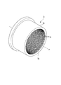
- the sealing device 5 is provided on the outer peripheral side of the rotor 2 and seals the flow of the process gas G between the three-stage impeller group 4A and the three-stage impeller group 4B. As shown in FIGS. 2 and 3, the seal device 5 includes a seal body 5 a that is disposed so as to cover the outer peripheral surface 2 a of the rotor 2.
- the seal body 5a is an annular member that is disposed opposite to the outer peripheral surface 2a of the rotor 2 with a predetermined gap S for rotating the rotor 2.
- a plurality of holes 5c are formed in the seal body 5a.
- the hole 5c is opened at an inner peripheral surface (opposing surface) 5b facing the outer peripheral surface 2a of the rotor 2 in the seal body 5a.
- the hole 5c is recessed from the opening toward the outside in the radial direction of the axis P. 3 to 8 schematically show the seal body 5a with a reduced number of holes 5c.
- the hole 5c includes a cylindrical hole body 5cA extending from the opening of the inner peripheral surface 5b toward the radially outer side of the axis P, and an inner peripheral surface 5b with respect to the hole body 5cA. And a conical reduced diameter portion 5cB formed on the opposite side, that is, on the radially outer side of the hole body 5cA.
- the reduced diameter portion 5cB is formed so that the inner diameter becomes smaller as it is spaced radially outward from the hole body 5cA.
- the hole body 5cA communicates with the reduced diameter portion 5cB.
- the farthest part from the hole body 5cA in the reduced diameter part 5cB is the bottom 5cC of the hole 5c.
- the plurality of holes 5c are recessed from the inner peripheral surface 5b and arranged.
- the seal body 5a is formed with an ejection flow path 5d communicating with the guide flow path 6f of the casing 6 and each of the plurality of holes 5c.
- the ejection channel 5d includes a distribution channel 5dA that communicates with each of the plurality of holes 5c, and a supply channel 5dB that communicates with each of the distribution channel 5dA and the guide channel 6f of the casing 6. That is, the guide flow path 6f of the casing 6 is continuous with the supply flow path 5dB of the ejection flow path 5d, and the supply flow path 5dB is continuous with the distribution flow path 5dA.
- the supply channel 5 dB communicates with the central portion of the distribution channel 5 dA in the direction of the axis P.
- the axis P is opposite to the first inner surface 5dC on the axis P side of the distribution channel 5dA and the first inner surface 5dC of the distribution channel 5dA.
- the second inner surface 5dD on the side is parallel to the axis P. That is, the first inner surface 5dC on the radially inner side of the distribution channel 5dA and the second inner surface 5dD on the radially outer side of the distribution channel 5dA are parallel to the axis P, respectively.
- the distribution channel 5dA of the ejection channel 5d and the bottom 5cC of the hole 5c communicate with each other via a columnar connection channel (a portion communicating with the ejection channel 5d in the hole 5c) 5e.
- the inner diameter of the connection channel 5e is constant regardless of the position in the axis P direction.
- the operation of the sealing device 5 configured as described above will be described.
- a part of the process gas G flows in the gap S between the outer peripheral surface 2a of the rotor 2 and the inner peripheral surface 5b of the seal body 5a by compressing the process gas G.
- the pressure of the process gas G is higher on the three-stage impeller group 4B side than on the three-stage impeller group 4A side. Therefore, in the rotating machine 1, as shown in FIG. 3, the process gas G flows through the gap S from the other side D2 in the direction of the axis P toward the one side D1, as indicated by an arrow A1. At this time, a part of the impurities contained in the process gas G tends to flow into the hole 5c.
- the process gas G Since the pressure of the process gas G is higher on the three-stage impeller group 4B side than on the three-stage impeller group 4A side, the process gas G is ejected through the guide flow path 6f of the casing 6 as indicated by an arrow A2. It flows toward 5d.
- the process gas G flows through the supply flow path 5dB and the distribution flow path 5dA of the ejection flow path 5d.
- the process gas G flowing into the distribution channel 5dA flows from the connecting portion 5dE where the supply channel 5dB is continuous with the distribution channel 5dA toward the one side D1 and the other side D2 in the direction of the axis P.
- the process gas G passes through the connection channel 5e and is ejected from the bottom 5cC of each hole 5c as shown by an arrow A3 in FIGS.
- the process gas G has a pressure lower than the pressure loss as it flows through the supply channel 5 dB, the distribution channel 5 dA, the connection channel 5 e, and the hole 5 c.
- the process gas G ejected from the bottom 5cC of each hole 5c makes it difficult for impurities contained in the process gas G flowing through the gap S to flow into the hole 5c. Even if the hole 5c is blocked by impurities or the like, the impurities or the like in the hole 5c are removed by the momentum of the process gas G ejected from the bottom 5cC.
- the process gas G ejected from the bottom 5cC of each hole 5c merges with the process gas G flowing through the gap S and flows toward the three-stage impeller group 4A.
- the process gas G flowing through the ejection flow path 5d is ejected from the bottom 5cC of the hole 5c.
- the process gas G flowing through the ejection flow path 5d is ejected from the bottom 5cC of the hole 5c.
- the inner diameter of the plurality of connection flow paths 5e is on the axis P on the other side D2 of the connection portion 5dE where the supply flow path 5dB is continuous with the distribution flow path 5dA. It may increase as it goes from one side D1 along the other side D2. As it goes to the other side D2 from the connecting portion 5dE, the pressure of the process gas G decreases due to the pressure loss of the distribution flow path 5dA, and it becomes difficult to eject the process gas G from the bottom 5cC of the hole 5c.
- the inner diameters of the plurality of connection flow paths 5e By changing the inner diameters of the plurality of connection flow paths 5e as described above, the influence of pressure loss due to the distribution flow path 5dA is reduced, and the amount of the process gas G ejected from the bottom 5cC of the hole 5c is changed to the position in the axis P direction. However, it can be made uniform. Similarly, the inner diameters of the plurality of connection flow paths 5e may increase from the other side D2 along the axis P toward the one side D1 on the one side D1 than the coupling portion 5dE.
- the second inner surface 5dD of the distribution channel 5dA extends from the first inner surface 5dC toward the other side D2 from the one side D1 along the axis P. You may incline so that it may space apart. In other words, the channel cross-sectional area of the distribution channel 5dA may be increased from one side D1 along the axis P toward the other side D2. With this configuration, the internal space of the distribution channel 5dA is wider on the other side D2 than on the one side D1.
- the process gas G supplied from the supply flow path 5dB tends to flow toward the other side D2 rather than the one side D1 of the distribution flow path 5dA.
- the process gas G flowing through the gap S between the outer peripheral surface 2a of the rotor 2 and the inner peripheral surface 5b of the seal body 5a has a pressure on the other side D2 rather than one side D1 in the axis P direction due to pressure loss. high.
- the process gas G is easily ejected toward the rotor 2 from the hole 5c disposed on the other side D2 where the pressure of the process gas G is high in the gap S.
- the rotary machine 11 according to the second embodiment includes an on-off valve 12 provided in the guide flow path 6f in addition to the components of the rotary machine 1 according to the first embodiment.
- an on-off valve 12 As the on-off valve 12, a valve having a known configuration can be used.
- the valve body incorporated in the on-off valve 12 can be driven to open and close by a valve drive motor.
- the on-off valve 12 switches between an open state in which the process gas G flows through the ejection flow path 5d and a closed state in which the process gas G does not flow through the ejection flow path 5d.
- the process gas G In the open state in which the process gas G flows through the ejection channel 5d, the process gas G is ejected from the bottom 5cC of each hole 5c, and in the closed state in which the process gas G does not flow in the ejection channel 5d, the process gas G is in each hole 5c. Does not erupt from.
- the hole 5c of the rotating machine 11 can be prevented from being blocked by impurities or the like. Furthermore, the on-off valve 12 can easily switch between a state in which the process gas G is ejected from the hole 5c and a state in which the process gas G is not ejected. The timing at which the process gas G is ejected from the bottom 5cC of each hole 5c can be controlled.
- a cleaning liquid channel 6g for supplying the cleaning liquid H to the ejection channel 5d is formed in the casing 6. .
- One end of the cleaning liquid flow path 6g communicates with the guide flow path 6f.
- a fluid supply pump (not shown) is provided at the other end of the cleaning liquid flow path 6g.
- the cleaning liquid H known ones such as hydrocarbons and fluorines can be appropriately selected and used.
- the cleaning liquid H supplied from the cleaning liquid flow path 6g is mixed with the process gas G at a connecting portion between the guide flow path 6f and the cleaning liquid flow path 6g to be a mixed fluid, and is supplied to each hole 5c.
- the cleaning liquid H in the mixed fluid ejected from the bottom 5cC of the hole 5c cleans the inside of the hole 5c. By ejecting not only the process gas G but also the cleaning liquid H from the bottom 5cC of the hole 5c, impurities and the like deposited in the hole 5c are removed.
- the hole 5c of the rotary machine 16 can be prevented from being blocked by impurities or the like. Furthermore, by cleaning the inside of the hole 5c with the cleaning liquid H, impurities and the like can be effectively removed from the hole 5c.
- the process gas G compressed by the three-stage impeller group 4B is ejected from the bottom 5cC of each hole 5c.
- the process gas G compressed by another compression device may be ejected from the bottom 5cC of each hole 5c.
- the fluid ejected from the bottom 5cC of each hole 5c may be other than the process gas G.
Landscapes
- Engineering & Computer Science (AREA)
- General Engineering & Computer Science (AREA)
- Mechanical Engineering (AREA)
- Structures Of Non-Positive Displacement Pumps (AREA)
- Sealing Using Fluids, Sealing Without Contact, And Removal Of Oil (AREA)
Abstract
シール装置(5)は、シール本体(5a)を有する。シール本体(5a)には、軸線(P)周りに回転するロータ(2)に対向する対向面(5b)から凹むように配列された複数の孔部(5c)と、孔部(5c)における底部(5cC)に流体を導き、流体を底部(5cC)から噴出する噴出流路(5d)と、が形成されている。
Description
本発明は、シール装置、及びこのシール装置を備える回転機械に関する。
本願は、2014年10月29日に、日本国に出願された特願2014-220708号に基づき優先権を主張し、この内容をここに援用する。
本願は、2014年10月29日に、日本国に出願された特願2014-220708号に基づき優先権を主張し、この内容をここに援用する。
従来、流体を圧縮する場合等に、遠心圧縮機等の回転機械が用いられている。この種の回転機械としては、例えば特許文献1に記載された遠心圧縮機が知られている。
遠心圧縮機は、ケーシング内部に複数の羽根車を有する。この遠心圧縮機は、ケーシングの吸込口から吸い込まれた気体(流体)を複数の羽根車の回転により圧縮し、ケーシングの吐出口から吐出する。各羽根車で圧縮された気体は、各羽根車の口金部の口金シール、各羽根車の間の中間段シール、及び最終段に設けられたバランスピストン部シールによってシールされている。
従来のシール構造としてラビリンスシール、ダンパシール等のシール装置が知られている。ダンパシールは、シール静止部表面に複数の孔部を設けたシール構造である。このダンパシールは、気体の漏れ低減効果とともに、減衰付与効果が大きい。ダンパシールには、ホールパターンシール、ハニカムシール等がある。
圧縮機の軸系において、通常は、ロータは両端に設置された軸受で保持されている。軸の振れ回りの不安定振動は、周方向に作用する流体不安定化力により励振される。従来、バランスピストン部シールにダンパシールを用いることにより、軸系に減衰を付与し、軸の振動を低減している。
ダンパシールには、複数の孔部が形成されている。このダンパシールを有する遠心圧縮機(回転機械)を長期間運転した場合、流体に含まれる不純物やスケール、金属粉、重化合物等(以下、不純物等と称する)がダンパシールの孔部内に堆積し、孔部を塞いでしまうという問題がある。
孔部が塞がれたダンパシールは環状シールとしてしか働かず、減衰性能は大きく低下する。
ダンパシールには、複数の孔部が形成されている。このダンパシールを有する遠心圧縮機(回転機械)を長期間運転した場合、流体に含まれる不純物やスケール、金属粉、重化合物等(以下、不純物等と称する)がダンパシールの孔部内に堆積し、孔部を塞いでしまうという問題がある。
孔部が塞がれたダンパシールは環状シールとしてしか働かず、減衰性能は大きく低下する。
本発明は、孔部が不純物等により塞がれるのを抑制したシール装置、及びこのシール装置を備える回転機械を提供する。
本発明の第一態様に係るシール装置は、軸線周りに回転するロータに対向する対向面から凹み、配列された複数の孔部と、前記孔部における底部に流体を導き、前記流体を前記底部から噴出する噴出流路と、が形成されたシール本体を有する。
この構成によれば、噴出流路から流体を供給し孔部の底部から流体を噴出することで、孔部が不純物等で塞がれていても、噴出される流体の勢いで不純物等が除去される。
この構成によれば、噴出流路から流体を供給し孔部の底部から流体を噴出することで、孔部が不純物等で塞がれていても、噴出される流体の勢いで不純物等が除去される。
本発明の第二態様に係るシール装置は、前記第一態様に係るシール装置において、前記噴出流路は、複数の前記孔部にそれぞれ連通する分配流路と、前記分配流路に連通する供給流路と、を有し、前記軸線を含む平面による断面において、前記分配流路の前記軸線側の第一の内面は前記軸線に平行であり、前記分配流路の前記第一の内面に対して前記軸線とは反対側の第二の内面は、前記軸線に沿う一方側から他方側に向かうにしたがって前記第一の内面から離間するように傾斜していてもよい。
この構成によれば、分配流路の内部空間は一方側よりも他方側の方が広くなる。分配流路を流れる流体の圧力損失により、噴出流路から供給された流体は分配流路の一方側よりも他方側の方に流れやすい。
ロータとシール本体との間に配される流体に、軸線に沿う方向に圧力差が有る場合でも、流体の圧力が高い側が分配流路の他方側となるようにロータに対してシール本体を配置する。これにより、流体の圧力が高い側に配された孔部からも流体がロータに向かって噴出しやすくなる。
この構成によれば、分配流路の内部空間は一方側よりも他方側の方が広くなる。分配流路を流れる流体の圧力損失により、噴出流路から供給された流体は分配流路の一方側よりも他方側の方に流れやすい。
ロータとシール本体との間に配される流体に、軸線に沿う方向に圧力差が有る場合でも、流体の圧力が高い側が分配流路の他方側となるようにロータに対してシール本体を配置する。これにより、流体の圧力が高い側に配された孔部からも流体がロータに向かって噴出しやすくなる。
本発明の第三態様に係るシール装置は、前記第一態様又は前記第二態様に係るシール装置において、複数の前記孔部における前記噴出流路に連通する部分の内径は、前記軸線に沿う一方側から他方側に向かうにしたがって大きくなってもよい。
この構成によれば、分配流路による圧力損失の影響を低減させ、孔部の底部から噴出する流体の量を軸線方向の位置によらず均一化させることができる。
この構成によれば、分配流路による圧力損失の影響を低減させ、孔部の底部から噴出する流体の量を軸線方向の位置によらず均一化させることができる。
本発明の第四態様に係る回転機械は、前記第一態様から第三態様のいずれか一の態様のシール装置と、前記ロータと、を備えることを特徴とする。
この構成によれば、回転機械が備えるシール装置の孔部が塞がれるのを抑制することができる。
この構成によれば、回転機械が備えるシール装置の孔部が塞がれるのを抑制することができる。
また、本発明の第五態様に係る回転機械は、前記第四態様に係る回転機械において、前記噴出流路を前記流体が流れる開状態と前記噴出流路を前記流体が流れない閉状態とを切り替える開閉弁を有してもよい。
この構成によれば、開閉弁により、孔部から流体が噴出させる状態と噴出させない状態とを容易に切り替えることができる。
この構成によれば、開閉弁により、孔部から流体が噴出させる状態と噴出させない状態とを容易に切り替えることができる。
また、本発明の第六態様に係る回転機械は、前記第四態様又は第五態様に係る回転機械において、前記噴出流路に洗浄液を供給するための洗浄液流路が形成された本体部を有してもよい。
この構成によれば、孔部内を洗浄液で洗浄することで、孔部内から不純物等を効果的に除去することができる。
この構成によれば、孔部内を洗浄液で洗浄することで、孔部内から不純物等を効果的に除去することができる。
本発明の一態様によれば、シール装置における孔部が不純物等により塞がれるのを抑制することができる。
《第一実施形態》
以下、本発明に係る第一実施形態のシール装置5を備えた回転機械1について、図1から図6を参照して説明する。図1に示すように、本実施形態における回転機械1は、複数のインペラ4を備えた多段式遠心圧縮機である。
以下、本発明に係る第一実施形態のシール装置5を備えた回転機械1について、図1から図6を参照して説明する。図1に示すように、本実施形態における回転機械1は、複数のインペラ4を備えた多段式遠心圧縮機である。
回転機械1は、軸線Pを中心としたロータ2と、ロータ2を軸線P周りに回転可能に支持する軸受3と、ロータ2に取り付けられて遠心力を利用してプロセスガス(流体)Gを圧縮する複数のインペラ4と、インペラ4同士の間に配されてロータ2の外周面2aに沿って設けられたシール装置5と、これらを外周側から覆うケーシング(本体部)6とを備えている。
なお、プロセスガスGとしては、公知の液体や気体を用いることができる。
なお、プロセスガスGとしては、公知の液体や気体を用いることができる。
ロータ2は、柱状をなして軸線Pが延びる方向(以下、軸線P方向とする)に延在している。ロータ2は、軸線P方向の両端で軸受3によって回転可能に支持されている。
軸受3は、ロータ2の両端部に一つずつ設けられ、ロータ2を回転可能に支持している。これらの軸受3は、それぞれケーシング6に取り付けられている。
軸受3は、ロータ2の両端部に一つずつ設けられ、ロータ2を回転可能に支持している。これらの軸受3は、それぞれケーシング6に取り付けられている。
インペラ4は、回転による遠心力を利用してプロセスガスGを圧縮する。インペラ4は、いわゆるクローズ型のインペラである。このインペラ4は、ディスク4aと、複数のブレード4cと、カバー4bとを備えている。
複数のインペラ4のディスク4aは、それぞれロータ2における軸線P方向の中央位置Cに向かって、軸線Pの径方向外側に漸次拡径する円盤状に形成されている。
ブレード4cは、ディスク4aから軸線P方向における中央位置Cとは反対側の端部側に突出するように形成されている。ブレード4cは、軸線Pの周方向に所定間隔をあけて複数形成されている。
カバー4bは、軸線P方向における端部側から複数のブレード4cを覆う。カバー4bは、ディスク4aに対向する円盤状に形成されている。
複数のインペラ4のディスク4aは、それぞれロータ2における軸線P方向の中央位置Cに向かって、軸線Pの径方向外側に漸次拡径する円盤状に形成されている。
ブレード4cは、ディスク4aから軸線P方向における中央位置Cとは反対側の端部側に突出するように形成されている。ブレード4cは、軸線Pの周方向に所定間隔をあけて複数形成されている。
カバー4bは、軸線P方向における端部側から複数のブレード4cを覆う。カバー4bは、ディスク4aに対向する円盤状に形成されている。
インペラ4は、軸線P方向両側に配された各軸受3の間のロータ2に複数取り付けられている。これらインペラ4は、軸線P方向においてブレード4cの向きが互いに反対側を向く二組の三段式インペラ群4A,4Bを構成している。これら三段式インペラ群4A、及び三段式インペラ群4Bにおいては、それぞれ軸線P方向の中央位置C側のプロセスガスGの圧力が最も高くなる。つまり、プロセスガスGは、三段式インペラ群4A及び三段式インペラ群4B各々で、軸線Pの方向の中央位置Cに向かって段階的に圧縮されながら流れる。
ケーシング6は、軸受3を支持するとともに、ロータ2、インペラ4、シール装置5をそれぞれ外周側から覆う。ケーシング6は、筒状に形成されている。
ケーシング6は、軸線P方向の一方側D1(図1中、三段式インペラ群4Bに対する三段式インペラ群4A側)に、吸込口6bAを備えている。吸込口6bAは、環状に形成された吸込流路6cAに接続されている。吸込流路6cAは、三段式インペラ群4Aの最も一方側D1に配されるインペラ4の流路と接続されている。つまり、吸込口6bAから流入するプロセスガスGは、吸込流路6cAを介して三段式インペラ群4Aへと導入される。
ケーシング6は、各インペラ4のブレード4c間に形成された流路同士を接続するケーシング流路6aA、6aBを備えている。
ケーシング6は、軸線P方向の中央位置C側に、排出口6eAを備えている。この排出口6eAは、環状に形成された排出流路6dAに接続されている。排出流路6dAは、三段式インペラ群4Aの最も他方側D2(図1中、三段式インペラ群4Aに対する三段式インペラ群4B側)に配されるインペラ4の流路に接続されている。つまり、三段式インペラ群4Aの最も他方側D2に配されるインペラ4で圧縮されたプロセスガスGは、排出流路6dAを介して排出口6eAからケーシング6の外部に排出される。
ケーシング6は、中央位置Cを境にして、軸線P方向の一方側D1と他方側D2とが対称に形成されている。ケーシング6の他方側D2には、ケーシング流路6aB、吸込口6bB、吸込流路6cB、排出流路6dB、排出口6eBが形成されている。このケーシング6の他方側D2に配された三段式インペラ群4Bは、一方側D1の三段式インペラ群4Aで圧縮したプロセスガスGを更に圧縮する。
つまり、ケーシング6の他方側D2においては、排出口6eAから排出されたプロセスガスGが吸込口6bBに送り込まれる。その後、吸込口6bBから流入したプロセスガスGは、吸込流路6cBを介して三段式インペラ群4Bに供給されて段階的に圧縮される。
三段式インペラ群4Bによって圧縮されたプロセスガスGは、排出流路6dBを介して排出口6eBからケーシング6の外部に排出される。
ケーシング6には、三段式インペラ群4Bのうち軸線P方向の一方側D1の排出流路6dBに一端部が連通する案内流路6fが形成されている。
三段式インペラ群4Bによって圧縮されたプロセスガスGは、排出流路6dBを介して排出口6eBからケーシング6の外部に排出される。
ケーシング6には、三段式インペラ群4Bのうち軸線P方向の一方側D1の排出流路6dBに一端部が連通する案内流路6fが形成されている。
上述したように三段式インペラ群4Aにおいて圧縮されたプロセスガスGは、三段式インペラ群4Bに導入されて更なる圧縮が行われて中央位置C付近に到達する。そのため、三段式インペラ群4Aと三段式インペラ群4Bとの間には圧力差が生じる。具体的には、三段式インペラ群4Bの方が三段式インペラ群4Aよりも高い圧力になる。さらに、中央位置C付近においては、ロータ2の外周面2aとケーシング6の内周面との間に、隙間Sが形成されている。そのため、プロセスガスGは、隙間Sを通じて三段式インペラ群4Bが配置されている軸線P方向の他方側D2を上流側として、三段式インペラ群4Aが配置されている軸線P方向の一方側D1の下流側に向かって流れようとしてしまう。
そこで、この実施形態におけるシール装置5は、上流側である三段式インペラ群4Bから下流側である三段式インペラ群4AへのプロセスガスGの流れを抑制するために、中央位置C付近に設けられている。
そこで、この実施形態におけるシール装置5は、上流側である三段式インペラ群4Bから下流側である三段式インペラ群4AへのプロセスガスGの流れを抑制するために、中央位置C付近に設けられている。
シール装置5は、ロータ2の外周側に設けられて、三段式インペラ群4Aと三段式インペラ群4Bとの間でのプロセスガスGの流通を封止する。シール装置5は、図2及び図3に示すように、ロータ2の外周面2aを覆って配置されるシール本体5aを有している。
シール本体5aは、ロータ2の外周面2aとの間にロータ2を回転させるための所定の隙間Sを有して対向配置される環状部材である。シール本体5aには、複数の孔部5cが形成されている。孔部5cは、シール本体5aにおけるロータ2の外周面2aと対向する内周面(対向面)5bで開口している。孔部5cは、この開口から軸線Pの径方向外側に向かって凹んでいる。
なお、図3から図8では、シール本体5aに形成される孔部5cの数を減らして模式的に示している。
なお、図3から図8では、シール本体5aに形成される孔部5cの数を減らして模式的に示している。
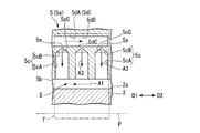
孔部5cは、図4に示すように、内周面5bの開口から軸線Pの径方向外側に向かって延びる円筒状の孔部本体5cAと、孔部本体5cAに対するおける内周面5bとは反対側、つまり孔部本体5cAの径方向外側に形成された円錐状の縮径部5cBとを有している。
縮径部5cBは、孔部本体5cAから径方向外側に離間するにしたがって、内径が小さくなるように形成されている。孔部本体5cAは、縮径部5cBと連通している。縮径部5cBにおける孔部本体5cAから最も遠い部分が、孔部5cの底部5cCとなっている。
複数の孔部5cは、前述したように、内周面5bから凹み、配列されている。
縮径部5cBは、孔部本体5cAから径方向外側に離間するにしたがって、内径が小さくなるように形成されている。孔部本体5cAは、縮径部5cBと連通している。縮径部5cBにおける孔部本体5cAから最も遠い部分が、孔部5cの底部5cCとなっている。
複数の孔部5cは、前述したように、内周面5bから凹み、配列されている。
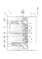
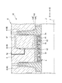
図3及び図4に示すように、シール本体5aには、ケーシング6の案内流路6f及び複数の孔部5cのそれぞれに連通する噴出流路5dが形成されている。噴出流路5dは、複数の孔部5cにそれぞれ連通する分配流路5dAと、分配流路5dA及びケーシング6の案内流路6fのそれぞれに連通する供給流路5dBとを有している。すなわち、ケーシング6の案内流路6fは噴出流路5dの供給流路5dBに連なり、供給流路5dBは分配流路5dAに連なる。供給流路5dBは、分配流路5dAの軸線P方向の中央部に連通している。
図4に示す軸線Pを含む仮想平面Tでの断面において、分配流路5dAの軸線P側の第一の内面5dC、及び分配流路5dAの第一の内面5dCに対して軸線Pとは反対側の第二の内面5dDは、それぞれ軸線Pに平行である。すなわち、分配流路5dAの径方向内側の第一の内面5dC、及び分配流路5dAの径方向外側の第二の内面5dDは、それぞれ軸線Pに平行である。
図4に示す軸線Pを含む仮想平面Tでの断面において、分配流路5dAの軸線P側の第一の内面5dC、及び分配流路5dAの第一の内面5dCに対して軸線Pとは反対側の第二の内面5dDは、それぞれ軸線Pに平行である。すなわち、分配流路5dAの径方向内側の第一の内面5dC、及び分配流路5dAの径方向外側の第二の内面5dDは、それぞれ軸線Pに平行である。
噴出流路5dの分配流路5dAと孔部5cの底部5cCとは、円柱状の接続流路(孔部5cにおける噴出流路5dに連通する部分)5eを介して連通している。この例では、接続流路5eの内径は軸線P方向の位置によらず一定である。
次に、上記構成のシール装置5の作用について説明する。
上記のような回転機械1では、プロセスガスGを圧縮することでロータ2の外周面2aとシール本体5aの内周面5bとの間の隙間SにプロセスガスGの一部が流れる。この回転機械1では、前述したように、三段式インペラ群4A側よりも三段式インペラ群4B側の方がプロセスガスGの圧力が高い。このため、この回転機械1では、図3に示すように、プロセスガスGが、隙間Sを軸線P方向の他方側D2から一方側D1に向かって、矢印A1に示すように流れる。このとき、プロセスガスGに含まれる不純物等の一部が孔部5c内に流れ込もうとする。
上記のような回転機械1では、プロセスガスGを圧縮することでロータ2の外周面2aとシール本体5aの内周面5bとの間の隙間SにプロセスガスGの一部が流れる。この回転機械1では、前述したように、三段式インペラ群4A側よりも三段式インペラ群4B側の方がプロセスガスGの圧力が高い。このため、この回転機械1では、図3に示すように、プロセスガスGが、隙間Sを軸線P方向の他方側D2から一方側D1に向かって、矢印A1に示すように流れる。このとき、プロセスガスGに含まれる不純物等の一部が孔部5c内に流れ込もうとする。
三段式インペラ群4A側よりも三段式インペラ群4B側の方がプロセスガスGの圧力が高いため、ケーシング6の案内流路6f内をプロセスガスGが矢印A2に示すように噴出流路5dに向かって流れる。
プロセスガスGは、噴出流路5dの供給流路5dB、分配流路5dAに導かれて流れる。分配流路5dAに流れ込んだプロセスガスGは、供給流路5dBが分配流路5dAに連なる連結部分5dEから軸線P方向の一方側D1、他方側D2に向かってそれぞれ流れる。プロセスガスGは接続流路5eを通り各孔部5cの底部5cCから図3及び図4に矢印A3に示すように噴出する。
プロセスガスGは、供給流路5dB、分配流路5dA、接続流路5e、及び孔部5c内を流れるのにしたがって圧力損失より圧力が低くなる。
プロセスガスGは、噴出流路5dの供給流路5dB、分配流路5dAに導かれて流れる。分配流路5dAに流れ込んだプロセスガスGは、供給流路5dBが分配流路5dAに連なる連結部分5dEから軸線P方向の一方側D1、他方側D2に向かってそれぞれ流れる。プロセスガスGは接続流路5eを通り各孔部5cの底部5cCから図3及び図4に矢印A3に示すように噴出する。
プロセスガスGは、供給流路5dB、分配流路5dA、接続流路5e、及び孔部5c内を流れるのにしたがって圧力損失より圧力が低くなる。
各孔部5cの底部5cCから噴出するプロセスガスGにより、隙間Sを流れるプロセスガスGに含まれる不純物等が孔部5c内に流れ込みにくくなる。孔部5cが不純物等で塞がれていても、底部5cCから噴出されるプロセスガスGの勢いで孔部5c内の不純物等が除去される。
各孔部5cの底部5cCから噴出したプロセスガスGは、隙間Sを流れるプロセスガスGに合流し、三段式インペラ群4A側に流れる。
各孔部5cの底部5cCから噴出したプロセスガスGは、隙間Sを流れるプロセスガスGに合流し、三段式インペラ群4A側に流れる。
したがって、実施形態のシール装置5及び回転機械1では、噴出流路5dを流れるプロセスガスGが孔部5cの底部5cCから噴出する。孔部5cの底部5cCからプロセスガスGを噴出することで、孔部5cが不純物等で塞がれていても、噴出されるプロセスガスGの勢いで不純物等が除去される。したがって、シール装置5の孔部5cが不純物等により塞がれるのを抑制することができる。
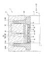
なお、本実施形態では、図5に示すように、例えば、供給流路5dBが分配流路5dAに連なる連結部分5dEよりも他方側D2において、複数の接続流路5eの内径は、軸線Pに沿う一方側D1から他方側D2に向かうにしたがって大きくなってもよい。この連結部分5dEよりも他方側D2に向かうにしたがって、分配流路5dAの圧力損失によりプロセスガスGの圧力が低くなり、孔部5cの底部5cCからプロセスガスGを噴出しにくくなる。複数の接続流路5eの内径を前述のように変えることで、分配流路5dAによる圧力損失の影響を低減させ、孔部5cの底部5cCから噴出するプロセスガスGの量を軸線P方向の位置によらず均一化させることができる。
同様に、連結部分5dEよりも一方側D1において、複数の接続流路5eの内径が、軸線Pに沿う他方側D2から一方側D1に向かうにしたがって大きくなってもよい。
同様に、連結部分5dEよりも一方側D1において、複数の接続流路5eの内径が、軸線Pに沿う他方側D2から一方側D1に向かうにしたがって大きくなってもよい。
図6に示すように、軸線Pを含む平面Tによる断面において、分配流路5dAの第二の内面5dDは、軸線Pに沿う一方側D1から他方側D2に向かうにしたがって第一の内面5dCから離間するように傾斜していてもよい。言い換えると、分配流路5dAの流路断面積は、軸線Pに沿う一方側D1から他方側D2に向かうにしたがって大きくしてもよい。このように構成することで、分配流路5dAの内部空間は一方側D1よりも他方側D2の方が広くなる。分配流路5dA内を流れるプロセスガスGの圧力損失により、供給流路5dBから供給されたプロセスガスGは分配流路5dAの一方側D1よりも他方側D2の方に流れやすい。また、ロータ2の外周面2aとシール本体5aの内周面5bとの間の隙間Sを流れるプロセスガスGは、圧力損失より軸線P方向の一方側D1よりも他方側D2の方が圧力が高い。
これにより、隙間SにおいてプロセスガスGの圧力が高い他方側D2に配された孔部5cからもプロセスガスGがロータ2に向かって噴出しやすくなる。
これにより、隙間SにおいてプロセスガスGの圧力が高い他方側D2に配された孔部5cからもプロセスガスGがロータ2に向かって噴出しやすくなる。
《第二実施形態》
次に、図7を参照して第二実施形態の回転機械11について説明する。第二実施形態においては第一実施形態と同様の構成要素には同一の符号を付して詳細な説明を省略する。
第二実施形態の回転機械11は、第一実施形態の回転機械1の各構成に加えて、案内流路6fに設けられた開閉弁12を備えている。開閉弁12は、公知の構成の弁を用いることができる。図示はしないが開閉弁12に内蔵される弁本体を弁駆動モータにより開閉駆動させることができる。これにより、開閉弁12は、噴出流路5dをプロセスガスGが流れる開状態と噴出流路5dをプロセスガスGが流れない閉状態とに切り替わる。
噴出流路5dをプロセスガスGが流れる開状態ではプロセスガスGは各孔部5cの底部5cCから噴出し、噴出流路5dをプロセスガスGが流れない閉状態ではプロセスガスGは各孔部5cから噴出しない。
次に、図7を参照して第二実施形態の回転機械11について説明する。第二実施形態においては第一実施形態と同様の構成要素には同一の符号を付して詳細な説明を省略する。
第二実施形態の回転機械11は、第一実施形態の回転機械1の各構成に加えて、案内流路6fに設けられた開閉弁12を備えている。開閉弁12は、公知の構成の弁を用いることができる。図示はしないが開閉弁12に内蔵される弁本体を弁駆動モータにより開閉駆動させることができる。これにより、開閉弁12は、噴出流路5dをプロセスガスGが流れる開状態と噴出流路5dをプロセスガスGが流れない閉状態とに切り替わる。
噴出流路5dをプロセスガスGが流れる開状態ではプロセスガスGは各孔部5cの底部5cCから噴出し、噴出流路5dをプロセスガスGが流れない閉状態ではプロセスガスGは各孔部5cから噴出しない。
したがって、実施形態の回転機械11によれば、回転機械11の孔部5cが不純物等により塞がれるのを抑制することができる。さらに、開閉弁12により、孔部5cからプロセスガスGを噴出させる状態と噴出させない状態とを容易に切り替えることができる。各孔部5cの底部5cCからプロセスガスGを噴出するタイミングをコントロールすることができる。
《第三実施形態》
次に、図8を参照して第三実施形態の回転機械16について説明する。第三実施形態においては第一実施形態と同様の構成要素には同一の符号を付して詳細な説明を省略する。
この第三実施形態の回転機械16は、第一実施形態の回転機械1の各構成に加えて、ケーシング6に噴出流路5dに洗浄液Hを供給するための洗浄液流路6gが形成されている。洗浄液流路6gの一端部は、案内流路6fに連通している。洗浄液流路6gの他端部には、図示しない流体供給ポンプが設けられている。
洗浄液Hとしては、炭化水素系、フッ素系等の公知のものを適宜選択して用いることができる。
次に、図8を参照して第三実施形態の回転機械16について説明する。第三実施形態においては第一実施形態と同様の構成要素には同一の符号を付して詳細な説明を省略する。
この第三実施形態の回転機械16は、第一実施形態の回転機械1の各構成に加えて、ケーシング6に噴出流路5dに洗浄液Hを供給するための洗浄液流路6gが形成されている。洗浄液流路6gの一端部は、案内流路6fに連通している。洗浄液流路6gの他端部には、図示しない流体供給ポンプが設けられている。
洗浄液Hとしては、炭化水素系、フッ素系等の公知のものを適宜選択して用いることができる。
洗浄液流路6gから供給された洗浄液Hは、案内流路6fと洗浄液流路6gとの接続部分でプロセスガスGに混合されて混合流体となり、各孔部5cに供給される。孔部5cの底部5cCから噴出した混合流体中の洗浄液Hは、孔部5c内を洗浄する。孔部5cの底部5cCからプロセスガスGだけでなく洗浄液Hを噴出させることで、孔部5c内に堆積した不純物等が除去される。
したがって、実施形態の回転機械16によれば、回転機械16の孔部5cが不純物等により塞がれるのを抑制することができる。さらに、孔部5c内を洗浄液Hで洗浄することで、孔部5c内から不純物等を効果的に除去することができる。
以上、本発明の実施の形態について図面を参照して詳述したが、具体的な構成はこの実施の形態に限られるものではなく、本発明の要旨を逸脱しない範囲の設計変更等も含まれる。
例えば、上記第1実施形態から第3実施形態では、各孔部5cの底部5cCから三段式インペラ群4Bで圧縮されたプロセスガスGを噴出させた。しかし、他の圧縮装置で圧縮したプロセスガスGを各孔部5cの底部5cCから噴出させてもよい。
各孔部5cの底部5cCから噴出させる流体は、プロセスガスG以外でもよい。
例えば、上記第1実施形態から第3実施形態では、各孔部5cの底部5cCから三段式インペラ群4Bで圧縮されたプロセスガスGを噴出させた。しかし、他の圧縮装置で圧縮したプロセスガスGを各孔部5cの底部5cCから噴出させてもよい。
各孔部5cの底部5cCから噴出させる流体は、プロセスガスG以外でもよい。
本発明の一態様によれば、シール装置における孔部が不純物等により塞がれるのを抑制することができる。
1,11,16…回転機械
2…ロータ
5…シール装置
5a…シール本体
5b…内周面(対向面)
5c…孔部
5cC…底部
5d…噴出流路
5dA…分配流路
5dB…供給流路
5dC…第一の内面
5dD…第二の内面
6…ケーシング(本体部)
6g…洗浄液流路
12…開閉弁
D1…一方側
D2…他方側
H…洗浄液
P…軸線
2…ロータ
5…シール装置
5a…シール本体
5b…内周面(対向面)
5c…孔部
5cC…底部
5d…噴出流路
5dA…分配流路
5dB…供給流路
5dC…第一の内面
5dD…第二の内面
6…ケーシング(本体部)
6g…洗浄液流路
12…開閉弁
D1…一方側
D2…他方側
H…洗浄液
P…軸線
Claims (6)
- 軸線周りに回転するロータに対向する対向面から凹み、配列された複数の孔部と、
前記孔部における底部に流体を導き、前記流体を前記底部から噴出する噴出流路と、
が形成されたシール本体を有するシール装置。 - 前記噴出流路は、
複数の前記孔部にそれぞれ連通する分配流路と、
前記分配流路に連通する供給流路と、
を有し、
前記軸線を含む平面による断面において、
前記分配流路の前記軸線側の第一の内面は前記軸線に平行であり、
前記分配流路の前記第一の内面に対して前記軸線とは反対側の第二の内面は、前記軸線に沿う一方側から他方側に向かうにしたがって前記第一の内面から離間するように傾斜している請求項1に記載のシール装置。 - 複数の前記孔部における前記噴出流路に連通する部分の内径は、前記軸線に沿う一方側から他方側に向かうにしたがって大きくなる請求項1に記載のシール装置。
- 請求項1に記載のシール装置を備える回転機械。
- 前記噴出流路を前記流体が流れる開状態と前記噴出流路を前記流体が流れない閉状態とを切り替える開閉弁を有する請求項4に記載の回転機械。
- 前記噴出流路に洗浄液を供給するための洗浄液流路が形成された本体部を有する請求項4又は5に記載の回転機械。
Priority Applications (1)
| Application Number | Priority Date | Filing Date | Title |
|---|---|---|---|
| US15/521,968 US20170321712A1 (en) | 2014-10-29 | 2015-10-20 | Seal device and rotary machine |
Applications Claiming Priority (2)
| Application Number | Priority Date | Filing Date | Title |
|---|---|---|---|
| JP2014220708A JP2016089856A (ja) | 2014-10-29 | 2014-10-29 | シール装置及び回転機械 |
| JP2014-220708 | 2014-10-29 |
Publications (1)
| Publication Number | Publication Date |
|---|---|
| WO2016067973A1 true WO2016067973A1 (ja) | 2016-05-06 |
Family
ID=55857314
Family Applications (1)
| Application Number | Title | Priority Date | Filing Date |
|---|---|---|---|
| PCT/JP2015/079574 Ceased WO2016067973A1 (ja) | 2014-10-29 | 2015-10-20 | シール装置及び回転機械 |
Country Status (3)
| Country | Link |
|---|---|
| US (1) | US20170321712A1 (ja) |
| JP (1) | JP2016089856A (ja) |
| WO (1) | WO2016067973A1 (ja) |
Citations (4)
| Publication number | Priority date | Publication date | Assignee | Title |
|---|---|---|---|---|
| JP2000002192A (ja) * | 1998-06-15 | 2000-01-07 | Aisin Seiki Co Ltd | コンプレッサ装置 |
| JP2009074423A (ja) * | 2007-09-20 | 2009-04-09 | Mitsubishi Heavy Ind Ltd | 圧縮機およびその運転方法 |
| WO2014087512A1 (ja) * | 2012-12-06 | 2014-06-12 | 三菱重工コンプレッサ株式会社 | シール装置、および、回転機械 |
| US20140191475A1 (en) * | 2011-03-24 | 2014-07-10 | Dresser-Rand Company | Interlocking hole pattern seal |
-
2014
- 2014-10-29 JP JP2014220708A patent/JP2016089856A/ja not_active Withdrawn
-
2015
- 2015-10-20 US US15/521,968 patent/US20170321712A1/en not_active Abandoned
- 2015-10-20 WO PCT/JP2015/079574 patent/WO2016067973A1/ja not_active Ceased
Patent Citations (4)
| Publication number | Priority date | Publication date | Assignee | Title |
|---|---|---|---|---|
| JP2000002192A (ja) * | 1998-06-15 | 2000-01-07 | Aisin Seiki Co Ltd | コンプレッサ装置 |
| JP2009074423A (ja) * | 2007-09-20 | 2009-04-09 | Mitsubishi Heavy Ind Ltd | 圧縮機およびその運転方法 |
| US20140191475A1 (en) * | 2011-03-24 | 2014-07-10 | Dresser-Rand Company | Interlocking hole pattern seal |
| WO2014087512A1 (ja) * | 2012-12-06 | 2014-06-12 | 三菱重工コンプレッサ株式会社 | シール装置、および、回転機械 |
Also Published As
| Publication number | Publication date |
|---|---|
| US20170321712A1 (en) | 2017-11-09 |
| JP2016089856A (ja) | 2016-05-23 |
Similar Documents
| Publication | Publication Date | Title |
|---|---|---|
| EP2902638B1 (en) | Seal device and rotary machine | |
| US8814499B2 (en) | Centrifugal compressor | |
| TWI445885B (zh) | 分子拖拉泵送機構 | |
| WO2011045928A1 (ja) | 圧縮機 | |
| CN102428280A (zh) | 具有轴向推力平衡器件的再生真空泵 | |
| WO2014060343A1 (en) | High efficiency low specific speed centrifugal pump | |
| WO2014087512A1 (ja) | シール装置、および、回転機械 | |
| WO2013111620A1 (ja) | 遠心式流体機械 | |
| JPWO2016121046A1 (ja) | 遠心圧縮機のケーシング、及び、遠心圧縮機 | |
| WO2016024409A1 (ja) | 遠心回転機械 | |
| WO2025124071A1 (zh) | 轴密封结构 | |
| WO2016043090A1 (ja) | 回転機械 | |
| US10947988B2 (en) | Impeller and centrifugal compressor | |
| JP2015532966A (ja) | ガス排出通路を有する平坦面付き液体リングポンプのポートプレート | |
| JP2016180349A (ja) | 回転機械 | |
| JP4952463B2 (ja) | 遠心圧縮機 | |
| JP2016089856A (ja) | シール装置及び回転機械 | |
| JP2018096514A (ja) | 軸シール装置、及び回転機械 | |
| JP2017141690A (ja) | 遠心回転機械 | |
| JP2006138216A (ja) | ターボ分子ポンプの軸封防塵構造 | |
| JP6233640B2 (ja) | シール装置及びこれを備える回転機械 | |
| JP5706792B2 (ja) | 遠心ポンプ | |
| JP6700893B2 (ja) | 羽根車、回転機械 | |
| JP6233643B2 (ja) | シール装置及びこれを備える回転機械 | |
| JP2018141413A (ja) | インペラ及び回転機械 |
Legal Events
| Date | Code | Title | Description |
|---|---|---|---|
| 121 | Ep: the epo has been informed by wipo that ep was designated in this application |
Ref document number: 15854942 Country of ref document: EP Kind code of ref document: A1 |
|
| WWE | Wipo information: entry into national phase |
Ref document number: 15521968 Country of ref document: US |
|
| NENP | Non-entry into the national phase |
Ref country code: DE |
|
| 122 | Ep: pct application non-entry in european phase |
Ref document number: 15854942 Country of ref document: EP Kind code of ref document: A1 |