WO2016063801A1 - Head mounted display, mobile information terminal, image processing device, display control program, and display control method - Google Patents
Head mounted display, mobile information terminal, image processing device, display control program, and display control method Download PDFInfo
- Publication number
- WO2016063801A1 WO2016063801A1 PCT/JP2015/079276 JP2015079276W WO2016063801A1 WO 2016063801 A1 WO2016063801 A1 WO 2016063801A1 JP 2015079276 W JP2015079276 W JP 2015079276W WO 2016063801 A1 WO2016063801 A1 WO 2016063801A1
- Authority
- WO
- WIPO (PCT)
- Prior art keywords
- head
- user
- display
- mounted display
- input
- Prior art date
Links
Images


Classifications
-
- A—HUMAN NECESSITIES
- A63—SPORTS; GAMES; AMUSEMENTS
- A63F—CARD, BOARD, OR ROULETTE GAMES; INDOOR GAMES USING SMALL MOVING PLAYING BODIES; VIDEO GAMES; GAMES NOT OTHERWISE PROVIDED FOR
- A63F13/00—Video games, i.e. games using an electronically generated display having two or more dimensions
- A63F13/20—Input arrangements for video game devices
- A63F13/21—Input arrangements for video game devices characterised by their sensors, purposes or types
- A63F13/214—Input arrangements for video game devices characterised by their sensors, purposes or types for locating contacts on a surface, e.g. floor mats or touch pads
-
- G—PHYSICS
- G06—COMPUTING; CALCULATING OR COUNTING
- G06F—ELECTRIC DIGITAL DATA PROCESSING
- G06F3/00—Input arrangements for transferring data to be processed into a form capable of being handled by the computer; Output arrangements for transferring data from processing unit to output unit, e.g. interface arrangements
- G06F3/01—Input arrangements or combined input and output arrangements for interaction between user and computer
- G06F3/011—Arrangements for interaction with the human body, e.g. for user immersion in virtual reality
- G06F3/012—Head tracking input arrangements
-
- A—HUMAN NECESSITIES
- A63—SPORTS; GAMES; AMUSEMENTS
- A63F—CARD, BOARD, OR ROULETTE GAMES; INDOOR GAMES USING SMALL MOVING PLAYING BODIES; VIDEO GAMES; GAMES NOT OTHERWISE PROVIDED FOR
- A63F13/00—Video games, i.e. games using an electronically generated display having two or more dimensions
- A63F13/20—Input arrangements for video game devices
- A63F13/24—Constructional details thereof, e.g. game controllers with detachable joystick handles
-
- A—HUMAN NECESSITIES
- A63—SPORTS; GAMES; AMUSEMENTS
- A63F—CARD, BOARD, OR ROULETTE GAMES; INDOOR GAMES USING SMALL MOVING PLAYING BODIES; VIDEO GAMES; GAMES NOT OTHERWISE PROVIDED FOR
- A63F13/00—Video games, i.e. games using an electronically generated display having two or more dimensions
- A63F13/25—Output arrangements for video game devices
-
- A—HUMAN NECESSITIES
- A63—SPORTS; GAMES; AMUSEMENTS
- A63F—CARD, BOARD, OR ROULETTE GAMES; INDOOR GAMES USING SMALL MOVING PLAYING BODIES; VIDEO GAMES; GAMES NOT OTHERWISE PROVIDED FOR
- A63F13/00—Video games, i.e. games using an electronically generated display having two or more dimensions
- A63F13/40—Processing input control signals of video game devices, e.g. signals generated by the player or derived from the environment
- A63F13/42—Processing input control signals of video game devices, e.g. signals generated by the player or derived from the environment by mapping the input signals into game commands, e.g. mapping the displacement of a stylus on a touch screen to the steering angle of a virtual vehicle
- A63F13/426—Processing input control signals of video game devices, e.g. signals generated by the player or derived from the environment by mapping the input signals into game commands, e.g. mapping the displacement of a stylus on a touch screen to the steering angle of a virtual vehicle involving on-screen location information, e.g. screen coordinates of an area at which the player is aiming with a light gun
-
- A—HUMAN NECESSITIES
- A63—SPORTS; GAMES; AMUSEMENTS
- A63F—CARD, BOARD, OR ROULETTE GAMES; INDOOR GAMES USING SMALL MOVING PLAYING BODIES; VIDEO GAMES; GAMES NOT OTHERWISE PROVIDED FOR
- A63F13/00—Video games, i.e. games using an electronically generated display having two or more dimensions
- A63F13/50—Controlling the output signals based on the game progress
- A63F13/53—Controlling the output signals based on the game progress involving additional visual information provided to the game scene, e.g. by overlay to simulate a head-up display [HUD] or displaying a laser sight in a shooting game
- A63F13/533—Controlling the output signals based on the game progress involving additional visual information provided to the game scene, e.g. by overlay to simulate a head-up display [HUD] or displaying a laser sight in a shooting game for prompting the player, e.g. by displaying a game menu
-
- G—PHYSICS
- G06—COMPUTING; CALCULATING OR COUNTING
- G06F—ELECTRIC DIGITAL DATA PROCESSING
- G06F1/00—Details not covered by groups G06F3/00 - G06F13/00 and G06F21/00
- G06F1/16—Constructional details or arrangements
- G06F1/1613—Constructional details or arrangements for portable computers
- G06F1/163—Wearable computers, e.g. on a belt
-
- G—PHYSICS
- G06—COMPUTING; CALCULATING OR COUNTING
- G06F—ELECTRIC DIGITAL DATA PROCESSING
- G06F1/00—Details not covered by groups G06F3/00 - G06F13/00 and G06F21/00
- G06F1/16—Constructional details or arrangements
- G06F1/1613—Constructional details or arrangements for portable computers
- G06F1/1633—Constructional details or arrangements of portable computers not specific to the type of enclosures covered by groups G06F1/1615 - G06F1/1626
- G06F1/1684—Constructional details or arrangements related to integrated I/O peripherals not covered by groups G06F1/1635 - G06F1/1675
- G06F1/1686—Constructional details or arrangements related to integrated I/O peripherals not covered by groups G06F1/1635 - G06F1/1675 the I/O peripheral being an integrated camera
-
- G—PHYSICS
- G06—COMPUTING; CALCULATING OR COUNTING
- G06F—ELECTRIC DIGITAL DATA PROCESSING
- G06F1/00—Details not covered by groups G06F3/00 - G06F13/00 and G06F21/00
- G06F1/16—Constructional details or arrangements
- G06F1/1613—Constructional details or arrangements for portable computers
- G06F1/1633—Constructional details or arrangements of portable computers not specific to the type of enclosures covered by groups G06F1/1615 - G06F1/1626
- G06F1/1684—Constructional details or arrangements related to integrated I/O peripherals not covered by groups G06F1/1635 - G06F1/1675
- G06F1/169—Constructional details or arrangements related to integrated I/O peripherals not covered by groups G06F1/1635 - G06F1/1675 the I/O peripheral being an integrated pointing device, e.g. trackball in the palm rest area, mini-joystick integrated between keyboard keys, touch pads or touch stripes
-
- G—PHYSICS
- G06—COMPUTING; CALCULATING OR COUNTING
- G06F—ELECTRIC DIGITAL DATA PROCESSING
- G06F1/00—Details not covered by groups G06F3/00 - G06F13/00 and G06F21/00
- G06F1/16—Constructional details or arrangements
- G06F1/1613—Constructional details or arrangements for portable computers
- G06F1/1633—Constructional details or arrangements of portable computers not specific to the type of enclosures covered by groups G06F1/1615 - G06F1/1626
- G06F1/1684—Constructional details or arrangements related to integrated I/O peripherals not covered by groups G06F1/1635 - G06F1/1675
- G06F1/1694—Constructional details or arrangements related to integrated I/O peripherals not covered by groups G06F1/1635 - G06F1/1675 the I/O peripheral being a single or a set of motion sensors for pointer control or gesture input obtained by sensing movements of the portable computer
-
- G—PHYSICS
- G06—COMPUTING; CALCULATING OR COUNTING
- G06F—ELECTRIC DIGITAL DATA PROCESSING
- G06F3/00—Input arrangements for transferring data to be processed into a form capable of being handled by the computer; Output arrangements for transferring data from processing unit to output unit, e.g. interface arrangements
- G06F3/01—Input arrangements or combined input and output arrangements for interaction between user and computer
- G06F3/011—Arrangements for interaction with the human body, e.g. for user immersion in virtual reality
- G06F3/013—Eye tracking input arrangements
-
- G—PHYSICS
- G06—COMPUTING; CALCULATING OR COUNTING
- G06F—ELECTRIC DIGITAL DATA PROCESSING
- G06F3/00—Input arrangements for transferring data to be processed into a form capable of being handled by the computer; Output arrangements for transferring data from processing unit to output unit, e.g. interface arrangements
- G06F3/01—Input arrangements or combined input and output arrangements for interaction between user and computer
- G06F3/016—Input arrangements with force or tactile feedback as computer generated output to the user
-
- G—PHYSICS
- G06—COMPUTING; CALCULATING OR COUNTING
- G06F—ELECTRIC DIGITAL DATA PROCESSING
- G06F3/00—Input arrangements for transferring data to be processed into a form capable of being handled by the computer; Output arrangements for transferring data from processing unit to output unit, e.g. interface arrangements
- G06F3/01—Input arrangements or combined input and output arrangements for interaction between user and computer
- G06F3/03—Arrangements for converting the position or the displacement of a member into a coded form
- G06F3/0304—Detection arrangements using opto-electronic means
- G06F3/0325—Detection arrangements using opto-electronic means using a plurality of light emitters or reflectors or a plurality of detectors forming a reference frame from which to derive the orientation of the object, e.g. by triangulation or on the basis of reference deformation in the picked up image
-
- G—PHYSICS
- G06—COMPUTING; CALCULATING OR COUNTING
- G06F—ELECTRIC DIGITAL DATA PROCESSING
- G06F3/00—Input arrangements for transferring data to be processed into a form capable of being handled by the computer; Output arrangements for transferring data from processing unit to output unit, e.g. interface arrangements
- G06F3/01—Input arrangements or combined input and output arrangements for interaction between user and computer
- G06F3/03—Arrangements for converting the position or the displacement of a member into a coded form
- G06F3/033—Pointing devices displaced or positioned by the user, e.g. mice, trackballs, pens or joysticks; Accessories therefor
- G06F3/0346—Pointing devices displaced or positioned by the user, e.g. mice, trackballs, pens or joysticks; Accessories therefor with detection of the device orientation or free movement in a 3D space, e.g. 3D mice, 6-DOF [six degrees of freedom] pointers using gyroscopes, accelerometers or tilt-sensors
-
- G—PHYSICS
- G06—COMPUTING; CALCULATING OR COUNTING
- G06F—ELECTRIC DIGITAL DATA PROCESSING
- G06F3/00—Input arrangements for transferring data to be processed into a form capable of being handled by the computer; Output arrangements for transferring data from processing unit to output unit, e.g. interface arrangements
- G06F3/01—Input arrangements or combined input and output arrangements for interaction between user and computer
- G06F3/03—Arrangements for converting the position or the displacement of a member into a coded form
- G06F3/041—Digitisers, e.g. for touch screens or touch pads, characterised by the transducing means
- G06F3/0412—Digitisers structurally integrated in a display
-
- G—PHYSICS
- G06—COMPUTING; CALCULATING OR COUNTING
- G06F—ELECTRIC DIGITAL DATA PROCESSING
- G06F3/00—Input arrangements for transferring data to be processed into a form capable of being handled by the computer; Output arrangements for transferring data from processing unit to output unit, e.g. interface arrangements
- G06F3/01—Input arrangements or combined input and output arrangements for interaction between user and computer
- G06F3/048—Interaction techniques based on graphical user interfaces [GUI]
- G06F3/0487—Interaction techniques based on graphical user interfaces [GUI] using specific features provided by the input device, e.g. functions controlled by the rotation of a mouse with dual sensing arrangements, or of the nature of the input device, e.g. tap gestures based on pressure sensed by a digitiser
- G06F3/0488—Interaction techniques based on graphical user interfaces [GUI] using specific features provided by the input device, e.g. functions controlled by the rotation of a mouse with dual sensing arrangements, or of the nature of the input device, e.g. tap gestures based on pressure sensed by a digitiser using a touch-screen or digitiser, e.g. input of commands through traced gestures
- G06F3/04883—Interaction techniques based on graphical user interfaces [GUI] using specific features provided by the input device, e.g. functions controlled by the rotation of a mouse with dual sensing arrangements, or of the nature of the input device, e.g. tap gestures based on pressure sensed by a digitiser using a touch-screen or digitiser, e.g. input of commands through traced gestures for inputting data by handwriting, e.g. gesture or text
-
- G—PHYSICS
- G06—COMPUTING; CALCULATING OR COUNTING
- G06F—ELECTRIC DIGITAL DATA PROCESSING
- G06F3/00—Input arrangements for transferring data to be processed into a form capable of being handled by the computer; Output arrangements for transferring data from processing unit to output unit, e.g. interface arrangements
- G06F3/14—Digital output to display device ; Cooperation and interconnection of the display device with other functional units
- G06F3/147—Digital output to display device ; Cooperation and interconnection of the display device with other functional units using display panels
-
- G—PHYSICS
- G06—COMPUTING; CALCULATING OR COUNTING
- G06V—IMAGE OR VIDEO RECOGNITION OR UNDERSTANDING
- G06V40/00—Recognition of biometric, human-related or animal-related patterns in image or video data
- G06V40/10—Human or animal bodies, e.g. vehicle occupants or pedestrians; Body parts, e.g. hands
- G06V40/103—Static body considered as a whole, e.g. static pedestrian or occupant recognition
-
- G—PHYSICS
- G09—EDUCATION; CRYPTOGRAPHY; DISPLAY; ADVERTISING; SEALS
- G09G—ARRANGEMENTS OR CIRCUITS FOR CONTROL OF INDICATING DEVICES USING STATIC MEANS TO PRESENT VARIABLE INFORMATION
- G09G3/00—Control arrangements or circuits, of interest only in connection with visual indicators other than cathode-ray tubes
- G09G3/001—Control arrangements or circuits, of interest only in connection with visual indicators other than cathode-ray tubes using specific devices not provided for in groups G09G3/02 - G09G3/36, e.g. using an intermediate record carrier such as a film slide; Projection systems; Display of non-alphanumerical information, solely or in combination with alphanumerical information, e.g. digital display on projected diapositive as background
- G09G3/003—Control arrangements or circuits, of interest only in connection with visual indicators other than cathode-ray tubes using specific devices not provided for in groups G09G3/02 - G09G3/36, e.g. using an intermediate record carrier such as a film slide; Projection systems; Display of non-alphanumerical information, solely or in combination with alphanumerical information, e.g. digital display on projected diapositive as background to produce spatial visual effects
-
- G—PHYSICS
- G09—EDUCATION; CRYPTOGRAPHY; DISPLAY; ADVERTISING; SEALS
- G09G—ARRANGEMENTS OR CIRCUITS FOR CONTROL OF INDICATING DEVICES USING STATIC MEANS TO PRESENT VARIABLE INFORMATION
- G09G5/00—Control arrangements or circuits for visual indicators common to cathode-ray tube indicators and other visual indicators
-
- G—PHYSICS
- G06—COMPUTING; CALCULATING OR COUNTING
- G06F—ELECTRIC DIGITAL DATA PROCESSING
- G06F2203/00—Indexing scheme relating to G06F3/00 - G06F3/048
- G06F2203/048—Indexing scheme relating to G06F3/048
- G06F2203/04808—Several contacts: gestures triggering a specific function, e.g. scrolling, zooming, right-click, when the user establishes several contacts with the surface simultaneously; e.g. using several fingers or a combination of fingers and pen
-
- G—PHYSICS
- G09—EDUCATION; CRYPTOGRAPHY; DISPLAY; ADVERTISING; SEALS
- G09G—ARRANGEMENTS OR CIRCUITS FOR CONTROL OF INDICATING DEVICES USING STATIC MEANS TO PRESENT VARIABLE INFORMATION
- G09G2354/00—Aspects of interface with display user
Definitions
- the present invention relates to display control technology, and more particularly to a head mounted display, a display control program, a display control method, and a display system.
- a game is played by operating a controller or the like while wearing a head-mounted display connected to a game machine on the head and watching the screen displayed on the head-mounted display.
- a head-mounted display connected to a game machine on the head and watching the screen displayed on the head-mounted display.
- the user's field of view extends beyond the display screen, so it may not be possible to concentrate on the display screen or lack of immersion in the game. There is.
- the head mounted display since the user does not see any video other than the video displayed on the head mounted display, the feeling of immersion in the video world is increased and the entertainment property of the game is further enhanced.
- the present inventor has recognized that more user-friendly input technology is necessary in order to allow more user groups to enjoy a game using a head mounted display.
- a head-mounted display is a head-mounted display that can be mounted on a user's head, and the inner side when the head-mounted display is mounted on the user's head.
- An input capable of detecting that a part of the user's body is in contact with or close to the display device provided on the surface and the surface provided on the outer surface when the head mounted display is mounted on the user's head.
- the acquisition unit is provided on a surface that is on the outer side when a head mounted display that can be mounted on the user's head is mounted on the user's head.
- Still another aspect of the present invention is a display system.
- This display system includes a head-mounted display that can be worn on the user's head, and an image processing device that generates an image to be displayed on the head-mounted display.
- the head mounted display has a display device provided on the inner surface when the head mounted display is mounted on the user's head, and an outer surface when the head mounted display is mounted on the user's head.
- Based on the provided input device that can detect that a part of the user's body is in contact with or in proximity, and input information that is detected by the input device and indicates that the part of the user's body is in contact or in proximity
- a display control unit configured to acquire data of the generated image from the image processing apparatus and display the acquired image data on the display device.
- the image processing apparatus includes an image generation unit that acquires input information and generates image data based on the input information.
- the head-mounted display is a head-mounted display that can be mounted on a user's head, and a display device provided on an inner surface when the head-mounted display is mounted on the user's head, and the head-mounted display A part of the user's body that is detected by an input device that can detect that a part of the user's body is in contact with or close to the user's body is attached to the outer surface when the user is attached to the user's head.
- a display control unit that acquires image data generated based on input information indicating contact or proximity, and displays the acquired image data on a display device.
- Still another aspect of the present invention is a portable information terminal.
- This portable information terminal is a portable information terminal that can be carried by the user, and includes an input device that can detect that a part of the user's body is in contact with or close to the portable information terminal, and a head-mounted display that can be worn on the user's head.
- the portable information terminal is mounted on the surface that is outside the head-mounted display when it is mounted on the user's head, it indicates that a part of the user's body that is detected by the input device is in contact with or in proximity
- a communication unit that transmits input information to a device that generates an image to be displayed on a head-mounted display based on the input information.
- Still another aspect of the present invention is an image processing apparatus.
- this apparatus when a head mounted display that can be mounted on the user's head is mounted on the user's head, a part of the user's body that is mounted on a surface that is outside the head mounted display is in contact with or close to the user's head.
- a receiving unit that receives input information detected by an input device that can detect that a part of the user's body has touched or approached, and a head-mounted display based on the input information received by the receiving unit Generating the image data to be displayed on the display device provided on the inner surface of the head mounted display when the is mounted on the user's head, and the image data generated by the generating unit
- a transmission unit for transmitting to the mount display.
- the convenience of the user of the head mounted display can be improved.
- the head-mounted display is a display device that is worn on the user's head so as to cover both eyes of the user and allows viewing of still images and moving images displayed on a display screen provided in front of the user's eyes.
- the target displayed on the head-mounted display may be a content such as a movie or a TV program, but in this embodiment, an example in which the head-mounted display is used as a display device for displaying a game image will be described. To do.
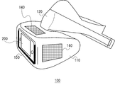
- FIG. 1 shows a use environment of the game system 1 according to the embodiment.
- the game system 1 includes a game device 10 that executes a game program, an input device 20 that inputs a user instruction to the game device 10, an imaging device 14 that captures an actual space around the user, and the game device 10. And a head-mounted display 100 that displays a generated game image.
- an input device for receiving a touch input by the user is provided on a surface that is outside the user when the head mounted display 100 is mounted.
- the input device 20 may not be used.
- the head mounted display 100 the user cannot visually recognize the surrounding situation, and thus it is difficult to search for an input device such as the input device 20 after the head mounted display 100 is mounted.
- an input device such as the input device 20 is moved greatly, it may hit an obstacle or the like around it.
- it is possible to accept input only by an input device that can accept touch input so there is no need to search for or swing around the input device 20.
- a user-friendly input interface that is easy to use even for a user who is not familiar with the game can be provided.
- the game apparatus 10 executes the game program based on an instruction input to the input device 20 or the input device provided on the outer surface of the head mounted display 100, generates an image signal indicating the processing result of the game program, and generates the generated image The signal is transmitted to the head mounted display 100.
- the head mounted display 100 receives an image signal generated by the game apparatus 10 and displays a game image. In addition, information related to the user's touch input to the input device provided on the outer surface of the head mounted display 100 is transmitted to the game device 10.
- the head mounted display 100 may be connected to the game apparatus 10 by a wired cable, or may be wirelessly connected by a wireless LAN (Local Area Network) or the like.
- the game image may be output to the display device 12.
- the display device 12 may be a television having a display and a speaker, or a computer display.
- the input device 20 has a function of transmitting an instruction input by a user to the game apparatus 10, and is configured as a wireless controller capable of wireless communication with the game apparatus 10 in this embodiment.
- the input device 20 and the game apparatus 10 may establish a wireless connection using a Bluetooth (registered trademark) (Bluetooth) protocol.
- Bluetooth registered trademark
- the input device 20 is not limited to the wireless controller, and may be a wired controller connected to the game apparatus 10 via a cable.
- the input device 20 is driven by a battery and is configured to have a plurality of buttons for operating instructions to advance the game.
- the operation instruction is transmitted to the game apparatus 10 by wireless communication.
- the imaging device 14 is a video camera composed of a CCD image sensor, a CMOS image sensor, or the like, and images a real space with a predetermined period to generate a frame image for each period.
- the imaging device 14 is connected to the game device 10 via a USB (Universal Serial Bus) or other interface.
- the image picked up by the image pickup device 14 is used in the game device 10 to derive the positions and postures of the input device 20 and the head mounted display 100.
- the imaging device 14 may be a distance measuring camera or a stereo camera capable of acquiring a distance. In this case, the imaging device 14 can acquire the distance between the imaging device 14 and the input device 20 or the head mounted display 100.
- the input device 20 has a light emitter configured to emit light in a plurality of colors.
- the illuminant emits light in the color designated by the game device 10 and is imaged by the imaging device 14.
- the imaging device 14 images the input device 20, generates a frame image, and supplies the frame image to the game device 10.
- the game apparatus 10 acquires a frame image, and derives position information of the light emitter in real space from the position and size of the image of the light emitter in the frame image.
- the game apparatus 10 treats the position information as a game operation instruction and reflects it in the game process such as controlling the movement of the player character.
- the game apparatus 10 according to the present embodiment has a function of processing a game application using not only an operation input such as a button of the input device 20 but also the positional information of the acquired light emitter image.
- the input device 20 has an acceleration sensor and a gyro sensor.
- the detection value of the sensor is transmitted to the game apparatus 10 at a predetermined cycle, and the game apparatus 10 acquires the detection value of the sensor and acquires the posture information of the input device 20 in the real space.
- the game apparatus 10 handles the posture information as a game operation instruction and reflects it in the game processing.
- FIG. 2 is an external view of the head mounted display 100 according to the embodiment.
- the head mounted display 100 includes a main body part 110, a head contact part 120, a touch pad 140, and a terminal mounting part 150.
- the position information of the user can be measured by a position sensor such as GPS (Global Positioning System) built in or externally attached to the head mounted display 100. Further, posture information such as the orientation and inclination of the head of the user wearing the head mounted display 100 can be measured by a posture sensor built in or externally attached to the head mounted display 100.
- GPS Global Positioning System
- the main body 110 includes a display, a position information acquisition sensor, a posture sensor, a communication device, and the like.
- the head contact unit 120 includes a biological information acquisition sensor capable of measuring biological information such as a user's body temperature, pulse, blood component, sweating, brain waves, and cerebral blood flow.
- An input device for receiving a touch input by a user is provided on the outer surface of the head mounted display 100.
- the input device may be a touch pad that is provided in advance in the head mounted display 100 and does not include a display device, or may be a touch panel that includes a display device.
- an external device such as a smartphone provided with a touch pad or a touch panel that functions as an input device may be detachably connected to the head mounted display 100.
- touch pad 140 is provided on the upper surface and side surface of main body 110, and portable information terminal 200 is detachably connected to terminal mounting portion 150 provided on the front of main body 110.
- the touch pad 140 provided on the temporal region may be any type of touch pad such as a matrix switch method, a resistive film method, a surface acoustic wave method, an infrared method, an electromagnetic induction method, a capacitance method, or the like. .
- the touch pad 140 may be a contact-type touch pad that detects an input when a user's finger or the like touches the surface, or may detect an input even when the user's finger or the like is close to the surface.
- a contact type touchpad may be used.
- the touch pad 140 may include a pressure-sensitive sensor that can detect the pressure of pressing against the surface, or may calculate the input intensity based on the area, voltage value, capacitance, etc. of the area where the input is detected. Good.
- the touch pad 140 outputs the coordinates of the position where the input is detected.
- a terminal mounting portion 150 for detachably mounting the portable information terminal 200 is provided on the frontal head, and the user's portable information terminal 200 can be mounted.
- the portable information terminal 200 When the portable information terminal 200 is attached, the portable information terminal 200 functions as an input device.
- an image generated by the head mounted display 100 or information about the head mounted display 100 can be displayed on the display device of the portable information terminal 200.
- the head mounted display 100 may further be provided with a camera for photographing the user's eyes.
- the camera mounted on the head mounted display 100 can detect the user's line of sight, pupil movement, blinking, and the like.
- the head-mounted display 100 will be described.
- the display control method of the present embodiment is not limited to the head-mounted display 100 in a narrow sense, but includes glasses, glasses-type displays, glasses-type cameras, headphones, and headsets. (Headphones with microphones), earphones, earrings, ear-mounted cameras, hats, hats with cameras, hair bands, etc. can also be applied.
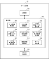
- FIG. 3 is a functional configuration diagram of the game apparatus 10.
- the game apparatus 10 includes a communication unit 302, a control unit 310, and a data holding unit 360.
- the control unit 310 includes an input information reception unit 311, an input position adjustment unit 312, an HMD image data generation unit 313, an HMD image data transmission unit 314, a touch panel display information generation unit 315, a touch panel display information transmission unit 316, and an HMD display information reception unit.
- 317, a captured image analysis unit 318, and a game control unit 319 are provided.
- the communication unit 302 controls communication with the head mounted display 100, the portable information terminal 200, the input device 20, the imaging device 14, the display device 12, and the like.
- the data holding unit 360 holds program data for a game executed in the game apparatus 10 and various data used by the game program.
- the input information receiving unit 311 receives information of touch input by the user received by the head mounted display 100 and the portable information terminal 200 from the head mounted display 100 and the portable information terminal 200, respectively.
- the input information receiving unit 311 further receives information on the position and orientation of the head mounted display 100 from the head mounted display 100.
- the input information receiving unit 311 receives input information such as a button received by the input device 20 from the input device 20.
- the input position adjustment unit 312 associates the position of the touch input in the input information received by the input information receiving unit 311 with the position of the image displayed on the head mounted display 100.
- a user's touch input is received by a plurality of touch pads 140 arranged at different positions and the touch panel of portable information terminal 200, it is necessary to associate each touch area with a displayed image area. Details of the function of the input position adjustment unit 312 will be described later.
- the game control unit 319 executes the game program and advances the game based on the instruction input by the user received by the input information receiving unit 311.
- the HMD image data generation unit 313 generates a game image controlled by the game control unit 319.
- the HMD image data transmission unit 314 transmits the image data generated by the HMD image data generation unit 313 to the head mounted display 100.
- the touch panel display information generation unit 315 generates information to be displayed on the touch panel of the portable information terminal 200 as information related to the game controlled by the game control unit 319.
- the touch panel of the portable information terminal 200 cannot be viewed by a user wearing the head mounted display 100 during a game, but can display information for other people around the user.
- the touch panel display information transmission unit 316 transmits the display information generated by the touch panel display information generation unit 315 to the portable information terminal 200.
- the HMD display information receiving unit 317 receives information to be displayed on the display device of the head mounted display 100 from the portable information terminal 200.
- the display information received by the HMD display information receiving unit 317 is included in the image displayed on the head mounted display 100 by the HMD image data generating unit 313. Thereby, even during the game, the display information transmitted from the portable information terminal 200 can be displayed on the display device of the head mounted display 100 and made visible to the user.
- the captured image analysis unit 318 acquires an image captured by the imaging device 14, analyzes the acquired image, and calculates the positions and orientations of the head mounted display 100 and the input device 20.
- the game control unit 319 acquires the position and orientation of the input device 20 as an instruction from the user and reflects them in the progress of the game.
- the HMD image data generation unit 313 controls the viewpoint position and line-of-sight direction used when generating a game image based on the position and orientation of the head mounted display 100.
- FIG. 4 is a functional configuration diagram of the head mounted display 100.
- the head mounted display 100 includes an input interface 22, an output interface 30, a backlight 32, a communication control unit 40, a network adapter 42, an antenna 44, a storage unit 50, a GPS unit 60, a wireless unit 62, a posture sensor 64, and an external input / output terminal.
- An interface 70, an external memory 72, a clock unit 80, a display device 90, a touch pad 140, and a control unit 160 are provided.
- These functional blocks can be realized in various forms by hardware only, software only, or a combination thereof.
- the control unit 160 is a main processor that processes and outputs signals such as image signals and sensor signals, commands and data.
- the input interface 22 receives operation signals and setting signals from the touch pad 140 and the touch pad controller and supplies them to the control unit 160.
- the output interface 30 receives an image signal from the control unit 160 and causes the display device 90 to display the image signal.
- the backlight 32 supplies a backlight to the liquid crystal display that constitutes the display device 90.
- the communication control unit 40 transmits data input from the control unit 160 to the outside through wired or wireless communication via the network adapter 42 or the antenna 44.
- the communication control unit 40 also receives data from the outside via wired or wireless communication via the network adapter 42 or the antenna 44 and outputs the data to the control unit 160.
- the storage unit 50 temporarily stores data, parameters, operation signals, and the like processed by the control unit 160.
- the GPS unit 60 receives position information from a GPS satellite and supplies it to the control unit 160 in accordance with an operation signal from the control unit 160.
- the radio unit 62 receives position information from the radio base station and supplies it to the control unit 160 in accordance with an operation signal from the control unit 160.
- the attitude sensor 64 detects attitude information such as the orientation and inclination of the main body 110 of the head mounted display 100.
- the posture sensor 64 is realized by appropriately combining a gyro sensor, an acceleration sensor, an angular acceleration sensor, and the like.
- the external input / output terminal interface 70 is an interface for connecting peripheral devices such as a USB (Universal Serial Bus) controller.
- the external memory 72 is an external memory such as a flash memory.
- the clock unit 80 sets time information according to a setting signal from the control unit 160 and supplies time data to the control unit 160.
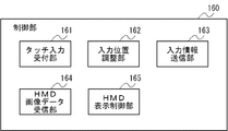
- FIG. 5 is a functional configuration diagram of the control unit 160 of the head mounted display 100.
- the control unit 160 includes a touch input reception unit 161, an input position adjustment unit 162, an input information transmission unit 163, an HMD image data reception unit 164, and an HMD display control unit 165.
- the touch input receiving unit 161 receives an input signal from the touch pad 140.
- the input position adjustment unit 162 associates the input position received by the touch input reception unit 161 with the position of the area to which the input area of the touch pad 140 is assigned in the image displayed on the display device 90.
- the input information transmission unit 163 transmits information indicating the position of the touch input adjusted by the input position adjustment unit 162 to the game apparatus 10.
- the HMD image data receiving unit 164 receives image data to be displayed on the display device 90 from the game device 10.
- the HMD display control unit 165 displays the image data received by the HMD image data receiving unit 164 on the display device 90.
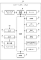
- FIG. 6 is a functional configuration diagram of the portable information terminal 200.
- the portable information terminal 200 includes a button 261, a communication unit 202, a control unit 210, a data holding unit 260, and a touch panel 262.
- the control unit 210 includes a touch input reception unit 211, an input position adjustment unit 212, an input information transmission unit 213, a touch panel display information reception unit 214, a touch panel display control unit 215, an HMD display information generation unit 216, and an HMD display information transmission unit 217. Is provided. These functional blocks can be realized in various forms by hardware only, software only, or a combination thereof.
- the communication unit 202 controls communication with the game apparatus 10.
- the data holding unit 260 stores program data of applications executed on the portable information terminal 200, data used by the applications, and the like.
- the touch panel 262 displays an image generated by the control unit 210 and detects a touch input by the user.
- the control unit 210 executes a cooperation application for accepting a touch input on the touch panel 262 as an input to a game that is executed by the game apparatus 10 and an image is displayed on the head mounted display 100.
- Touch input receiving unit 211 receives an input signal from touch panel 262.
- the input position adjustment unit 212 associates the input position received by the touch input reception unit 211 with the position of the area to which the input area of the touch panel 262 is assigned in the image displayed on the display device 90 of the head mounted display 100. Information regarding the area to which the input area of the touch panel 262 is assigned is acquired in advance from the head mounted display 100 or the game apparatus 10 when the cooperative application is activated.
- the input information transmission unit 213 transmits information indicating the position of the touch input adjusted by the input position adjustment unit 212 to the game apparatus 10.
- the touch panel display information receiving unit 214 receives information to be displayed on the touch panel 262 from the game apparatus 10.
- the touch panel display control unit 215 displays information received by the touch panel display information receiving unit 214 on the touch panel 262.
- the HMD display information generation unit 216 generates information to be displayed on the display device of the head mounted display 100.
- the HMD display information generation unit 216 acquires various types of notification information from other applications executed on the portable information terminal 200, and generates display information from the notification information according to a predetermined condition. For example, when a mail transmission / reception application of the portable information terminal 200 receives a mail, information such as a mail title, a predetermined number of character strings at the beginning of the text, and a sender may be extracted to generate display information.
- the HMD display information transmission unit 217 transmits the display information generated by the HMD display information generation unit 216 to the game apparatus 10.
- information to be displayed on the display device of the head mounted display 100 is once transmitted to the game device 10 and image data is generated by the game device 10, but in another example, the head mounted display Information to be displayed on the display device 100 may be transmitted directly to the head mounted display 100 and displayed on the display device 90 by the HMD display control unit 165 of the head mounted display 100.
- FIG. 7 shows an example of an image displayed on the display device 90 of the head mounted display 100.
- An image of a game controlled by the game apparatus 10 is displayed on the display device 90 of the head mounted display 100.
- FIG. 8 shows an example of an image displayed on the display device 90 of the head mounted display 100.
- the HMD image data generation unit 313 of the game apparatus 10 generates a completely dark game image, and the completely dark game image is displayed on the display device 90 of the head mounted display 100.
- FIG. 9 shows the touch panel 262 of the portable information terminal 200.
- the touch panel display information generation unit 315 of the game apparatus 10 generates information for displaying on the touch panel 262 the same image as that displayed on the display device 90 of the head mounted display 100, and the portable information terminal 200.
- the touch panel display control unit 215 displays the same image as the image displayed on the display device 90 of the head mounted display 100 on the touch panel 262.
- input information transmission unit 213 transmits information indicating that the downward flick input has been performed to game device 10.
- FIG. 10 shows an example of an image displayed on the display device 90 of the head mounted display 100.
- the game control unit 319 of the game apparatus 10 indicates that the flick input has been performed in the downward direction on the touch panel 262.
- the HMD image data generation unit 313 is instructed to generate a night vision image, assuming that night vision goggles are attached.
- the HMD image data generation unit 313 generates a night vision image, and the night vision image is displayed on the display device 90 of the head mounted display 100 as shown in FIG.
- an intuitive user-friendly operation system is provided. Can do.
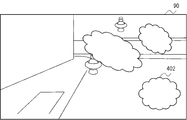
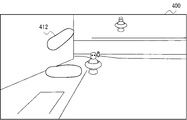
- FIG. 11 shows an example of an image displayed on the display device 90 of the head mounted display 100.
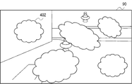
- an image of a game in which the cloudiness 402 is generated in the field of view is displayed.
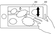
- FIG. 12 shows the touch panel 262 of the portable information terminal 200. It is assumed that a function is provided to remove the cloudiness 402 displayed at the swipe position by performing swipe input in an arbitrary direction at an arbitrary position on the touch panel 262.
- the input information transmission unit 213 transmits information indicating the swipe position to the game apparatus 10.
- FIG. 13 shows an example of an image displayed on the display device 90 of the head mounted display 100.
- the game control unit 319 of the game apparatus 10 removes the cloudiness 402 displayed at the position where the swipe input has been performed.
- the HMD image data generation unit 313 erases the removed cloudiness 402 from the game image.
- the user performs a swipe input in the area on the right side of the game image displayed on the touch panel 262.
- the game control unit 319 The cloudiness 402 displayed in the left area of the image is erased.
- the touch panel 262 when the same image as the game image displayed on the head mounted display 100 is displayed on the touch panel 262, from the viewpoint of the person watching the touch panel 262, the user performs a swipe input in the area on the right side of the game image. Since the cloudiness 402 displayed in the left area of the game image is erased and gives a sense of incongruity, the touch panel 262 is a mirror image obtained by horizontally inverting the game image displayed on the head mounted display 100. Is displayed.
- FIG. 14 shows an example of an image displayed on the display device 90 of the head mounted display 100.
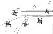
- an image of a game in which a spider 404 is attached to the field of view is displayed.
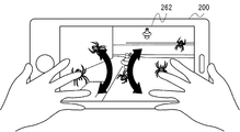
- FIG. 15 shows the touch panel 262 of the portable information terminal 200. It is assumed that a function for removing the spider 404 displayed at the swipe position by repeatedly performing swipe input in an arbitrary direction at an arbitrary position on the touch panel 262 is provided.
- input information transmission unit 213 transmits information indicating the swipe position and the number of times to game device 10.
- the input information transmission unit 213 transmits information indicating the swipe position to the game device 10 every time a swipe input is received, and the game control unit 319 of the game device 10 causes the user to perform a swipe input a predetermined number of times or more. It may be determined whether or not.
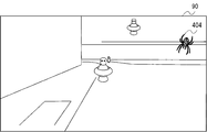
- FIG. 16 shows an example of an image displayed on the display device 90 of the head mounted display 100.
- the game control unit 319 of the game apparatus 10 is displayed at a position where the swipe input is performed a predetermined number of times or more.
- the spider 404 is removed.
- the HMD image data generation unit 313 erases the removed spider 404 from the game image.
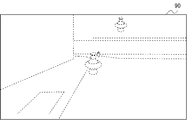
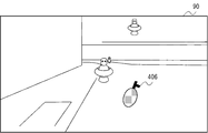
- FIG. 17 shows an example of an image displayed on the display device 90 of the head mounted display 100.
- an image of a game in which a flash van (flash acoustic grenade) 406 is arranged in the game field is displayed.
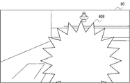
- FIG. 18 shows an example of an image displayed on the display device 90 of the head mounted display 100.
- the game control unit 319 causes the flash van 406 to explode.
- the HMD image data generation unit 313 generates a game image in which flash is generated by the explosion of the flash van 406, and the flash 408 is displayed on the display device 90 of the head mounted display 100.
- the flash 408 when the flash 408 is generated, if the user touches the touch panel 262 so that both eyes are covered with hands, the surrounding game field is displayed again as the flash 408 disappears. If the touch panel 262 is not touched so as to cover the screen, the flash 408 is blinded, and even if the flash 408 disappears, a white game image is displayed for a predetermined time, and the surrounding game field is not displayed.
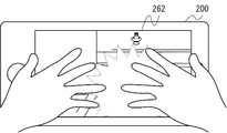
- FIG. 19 shows the touch panel 262 of the portable information terminal 200.
- a function is provided in which the palm is brought into contact with the touch panel 262 to cover both eyes and protect from the flash 408.
- the input information transmission unit 213 transmits information indicating a plurality of touched positions to the game apparatus 10.
- the game control unit 319 determines whether or not touch input corresponding to a predetermined condition indicating that the palm is touched is performed in each of the right half area and the left half area of the touch panel 262 at the moment of the explosion.
- the HMD image data generation unit 313 causes the surrounding game field to be displayed again with the disappearance of the flash 408. If it has not been performed, the predetermined time remains even if the flash 408 disappears. A white game image is displayed.
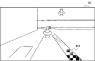
- FIG. 20 shows the touch panel 262 of the portable information terminal 200.
- a virtual player in a player character or first-person viewpoint game operated by the user Assume that a beam is fired from the eyes of a typical user.
- FIG. 21 shows an example of an image displayed on the display device 90 of the head mounted display 100.
- a function of emitting a beam is provided by performing touch input simultaneously at two points within an area of a predetermined range of the touch panel 262.
- the input information transmission unit 213 transmits information indicating a plurality of touched positions to the game apparatus 10.
- the game control unit 319 determines whether or not two touch inputs are simultaneously performed within a predetermined range, and if so, the HMD image data generation unit 313 indicates that the beam 410 is emitted. If not displayed, the beam 410 is not fired.
- the game control unit 319 calculates a path of the beam 410, and when an object exists on the path, the game control unit 319 executes processing when the beam 410 hits the object.
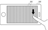
- FIG. 22 shows the touch panel 262 of the portable information terminal 200. As shown in FIG. 22, when the user performs touch input with a finger at an arbitrary position on the touch panel 262 for a predetermined time or longer, the finger is placed at a corresponding position on the game image displayed on the display device 90 of the head mounted display 100. Assume that an image is displayed.
- FIG. 23 shows an example of an image displayed on the display device 90 of the head mounted display 100.
- touch input at an arbitrary position on the touch panel 262 with a pressure of a predetermined time or more or a predetermined value or more
- the user's finger enters the virtual world image displayed on the display device 90 of the head mounted display 100 from the back.
- a function for displaying such a video effect is provided.
- the input information transmission unit 213 transmits information indicating a plurality of touched positions and time or pressure to the game apparatus 10.
- the game control unit 319 determines whether or not touch input has been performed with a pressure equal to or longer than a predetermined time or a predetermined value, and if so, the position at which the touch input has been performed on the HMD image data generation unit 313. If the user's finger 412 is not displayed, the finger 412 is not displayed. It may be displayed that the longer the time that touch input has been performed or the greater the pressure, the more the finger enters the near side.
- the same image as that displayed on the display device 90 of the head mounted display 100 is displayed on the touch panel 262 of the portable information terminal 200.
- the surrounding people can also enjoy watching the game that the user is running. For example, this is also effective when the parent wants to know the game being executed by the child.
- the display device 12 can be used for other purposes.
- An image different from the image displayed on the display device 90 may be displayed on the touch panel 262.
- the content displayed on the touch panel 262 may be determined by receiving an instruction from the user via the head mounted display 100, the portable information terminal 200, or the game apparatus 10, or the head mounted display 100, the portable information terminal 200, Alternatively, it may be automatically determined by the game apparatus 10.
- FIG. 24 shows an example of an image displayed on the touch panel 262 of the portable information terminal 200.
- information indicating the status of the game controlled by the game control unit 319 is displayed on the touch panel 262.
- the touch panel display information generation unit 315 of the game apparatus 10 acquires information indicating the state of the game controlled by the game control unit 319 and generates display information.
- the touch panel 262 displays that the game status is “matching with boss”, the remaining physical strength value of the enemy character indicating the game status in more detail, and a message from the user to the surrounding people Yes.
- FIG. 25 shows an example of an image displayed on the touch panel 262 of the portable information terminal 200. Also in the example of FIG. 25, information indicating the state of the game controlled by the game control unit 319 is displayed on the touch panel 262.
- the touch panel display information generation unit 315 of the game apparatus 10 acquires information indicating the state of the game controlled by the game control unit 319 and generates display information.
- the touch panel 262 displays that the game status is “watching movie”, the remaining number of seconds of the movie scene showing the game status in more detail, and a message from the user to surrounding people. .
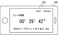
- FIG. 26 shows an example of an image displayed on the touch panel 262 of the portable information terminal 200. Also in the example of FIG. 25, information indicating the state of the game controlled by the game control unit 319 is displayed on the touch panel 262.
- the touch panel display information generation unit 315 of the game apparatus 10 acquires information indicating the state of the game controlled by the game control unit 319 and generates display information.
- the touch panel 262 displays a game play time and a rough estimate of the time required until the next save point. For example, this is also effective when the parent wants to limit the play time of the child game.
- the surrounding people can grasp the user's situation. Since it can, when talking to the user, it is possible to choose and talk to a situation where there is no problem. Therefore, the situation where the user is interrupted in a situation where the user does not want to be interrupted can be reduced, and the user can obtain an immersive feeling more effectively.
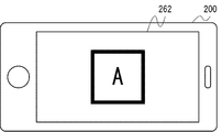
- FIG. 27 shows an example of an image displayed on the touch panel 262 of the portable information terminal 200.
- an image serving as a marker for the captured image analysis unit 318 to analyze the position and orientation of the head mounted display 100 is displayed on the touch panel 262.
- position of the head mounted display 100 can be improved. It is more effective to display different markers on a plurality of touch panels provided at a plurality of positions.
- the image to be a marker displayed on the touch panel 262 may be an arbitrary figure such as a barcode or an image such as a character.
- a portion around the eyes of a face such as a person or character may be displayed so that the user is wearing the character's face. Thereby, surrounding people can also be entertained.
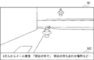
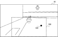
- FIG. 28 shows an example of an image displayed on the display device 90 of the head mounted display 100.
- the HMD display information generation unit 216 acquires information about the received mail and displays information to be displayed on the display device 90 of the head mounted display 100. Generate.
- the HMD display information receiving unit 317 of the game apparatus 10 receives information to be displayed on the display device 90 of the head mounted display 100 from the portable information terminal 200
- the HMD image data generating unit 313 receives image data including the received information. Generate.
- the sender of the mail received by the portable information terminal 200, the title, and the content at the beginning of the text are displayed in the display area 502 at the bottom of the screen on the display device 90 of the head mounted display 100. .
- the setting of information to be displayed on the display device 90 of the head mounted display 100 may be received from the user in advance via the touch panel 262 of the portable information terminal 200.
- the user can view necessary information regarding the portable information terminal 200 even while the head mounted display 100 is being used. If necessary, the user can use the portable information terminal 200 by interrupting viewing of the head mounted display 100. be able to.
- the information displayed on the display device 90 of the head mounted display 100 may not be displayed on the touch panel 262 of the portable information terminal 200. Thereby, it can prevent that a user's information is seen by the surrounding people.
- the position and size of the display area 502 for displaying information received from the portable information terminal 200 may be determined according to the game situation, or settings may be received from the user. Since the aspect ratio of the image to be displayed and the aspect ratio of the display area of the display device 90 do not match, if there are areas where no image is displayed on the top and bottom or the left and right of the screen, that area can be used as the display area 502. Good.
- the portable information terminal 200 may be operable while viewing the display device 90 of the head mounted display 100.
- the game device 10 transmits the instruction input received from the input device 20 or the like to the portable information terminal 200, and the cooperative application of the portable information terminal 200
- the received instruction input is transmitted to an application to be operated, for example, a mail application.
- the head mounted display 100 receives the instruction input received from the touch pad 140 or the like directly or via the game device 10. Send to.
- an application to be operated receives an instruction input directly or via a cooperative application.
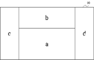
- FIG. 29 shows a correspondence relationship between the display area of the display device 90 of the head mounted display 100 and the input areas of the touch panel 262 and the touch pad 140.
- the input position adjustment unit 312 of the game apparatus 10 determines the positions of the inputs to the touch panel 262 and the touch pad 140. Then, it is associated with the position in the image displayed on the display device 90 of the head mounted display 100.
- the area a is the touch panel 262 of the portable information terminal 200
- the area b is the touch pad 140 provided on the upper surface of the head mounted display 100.
- the area c is associated with the touch pad 140 provided on the left head of the head mounted display 100
- the area d is associated with the touch pad 140 provided on the right head of the head mounted display 100.
- the input position adjustment unit 212 of the portable information terminal 200 is used for the touch panel 262, and the head mounted display is used for the touch pad 140.
- Each of the 100 input position adjustment units 162 associates the actual input position with the input position in the assigned input area.
- FIG. 30 shows an example of an image displayed on the display device 90 of the head mounted display 100.
- the input position adjusting unit 312 of the game apparatus 10 displays a marker 504 indicating the input position at the adjusted position, and on the touch panel 262 or the touch pad 140 that has received the input.
- a corresponding area frame 506 is displayed.
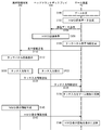
- FIG. 31 is a sequence diagram showing a procedure of the display control method according to the embodiment.
- the game control unit 319 of the game apparatus 10 controls the game (S100), and the HMD image data generation unit 313 generates image data to be displayed on the head mounted display 100 (S102).
- the HMD image data transmission unit 314 transmits the image data to the head mounted display 100 (S104), and the HMD display control unit 165 of the head mounted display 100 displays the image data on the display device 90 (S106).
- the touch panel display information generation unit 315 of the game apparatus 10 generates information for displaying the game status on the touch panel 262 of the portable information terminal 200 (S108), and the touch panel display information transmission unit 316 displays the display information on the portable information terminal. 200 (S110).
- the touch panel display control unit 215 of the portable information terminal 200 displays the display information on the touch panel 262 (S112).
- the touch input reception unit 211 receives input (S120), the input position adjustment unit 212 adjusts the position of the touch input, and the input information transmission unit 213. Transmits the input information to the game apparatus 10 (S124).
- the touch input receiving unit 161 receives an input (S122), the input position adjusting unit 162 adjusts the position of the touch input, and the input information transmitting unit. 163 transmits the input information to the game apparatus 10 (S126).
- the input position adjusting unit 312 adjusts the position of the touch input, and the game control unit 319 controls the touch input. (S128) and return to S100.
- the HMD display information transmission unit 217 sends the display information to the game device 10. Transmit (S142).
- the HMD display information receiving unit 317 of the game apparatus 10 receives display information from the portable information terminal 200, the HMD image data generating unit 313 reflects the display information on the display (S144), and the process returns to S102.
- a monocular image is displayed on the display device 90 of the head mounted display 100.
- a binocular stereoscopic image may be displayed.
- a binocular stereoscopic image may be displayed on the touch panel 262 of the portable information terminal 200, or a monocular image may be displayed on the touch panel 262.
- the game apparatus 10 controls the game and generates image data to be displayed on the display device 90 of the head mounted display 100.
- the configuration for controlling the game and generating image data. May be provided in the head mounted display 100.
- the game apparatus 10 may not be provided, and the portable information terminal 200 and the head mounted display 100 may communicate directly without using the game apparatus 10.
- the head-mounted display 100 is used in the game system.
- the technology described in the embodiment can also be used when displaying contents other than games.
- a user instruction can be easily input via a touch pad or a touch panel of a portable information terminal. be able to.
- the present invention can be used for a head mounted display.
Abstract
Provided is a head mounted display 100 which is wearable on the head of a user, wherein the head mounted display is equipped with: a display device that is disposed on a surface on the inside of the head mounted display 100 when the head mounted display is worn on the user's head; a touch pad 140 that is disposed on a surface on the outside of the head mounted display 100 when the head mounted display is worn on the user's head, and that is capable of detecting contact with or proximity to a part of the user's body; and a display control unit that acquires image data generated on the basis of input information detected by the touch pad 140 and indicating the occurrence of contact with or proximity to the part of the user's body, and that displays the acquired image data on the display device.
Description
本発明は、表示制御技術に関し、とくに、ヘッドマウントディスプレイ、表示制御プログラム、表示制御方法、及び表示システムに関する。
The present invention relates to display control technology, and more particularly to a head mounted display, a display control program, a display control method, and a display system.
ゲーム機に接続されたヘッドマウントディスプレイを頭部に装着して、ヘッドマウントディスプレイに表示された画面を見ながら、コントローラなどを操作してゲームプレイすることが行われている。ゲーム機に接続された通常の据え置き型のディスプレイでは、ディスプレイの画面の外側にもユーザの視野範囲が広がっているため、ディスプレイの画面に集中できなかったり、ゲームへの没入感に欠けたりすることがある。その点、ヘッドマウントディスプレイを装着すると、ヘッドマウントディスプレイに表示される映像以外はユーザは見ないため、映像世界への没入感が高まり、ゲームのエンタテインメント性を一層高める効果がある。
A game is played by operating a controller or the like while wearing a head-mounted display connected to a game machine on the head and watching the screen displayed on the head-mounted display. In a normal stationary display connected to a game machine, the user's field of view extends beyond the display screen, so it may not be possible to concentrate on the display screen or lack of immersion in the game. There is. On the other hand, when the head mounted display is mounted, since the user does not see any video other than the video displayed on the head mounted display, the feeling of immersion in the video world is increased and the entertainment property of the game is further enhanced.
本発明者は、より多くのユーザ層がヘッドマウントディスプレイを用いたゲームを楽しむことができるようにするためには、よりユーザフレンドリーな入力技術が必要であると認識した。
The present inventor has recognized that more user-friendly input technology is necessary in order to allow more user groups to enjoy a game using a head mounted display.
上記課題を解決するために、本発明のある態様のヘッドマウントディスプレイは、ユーザの頭部に装着可能なヘッドマウントディスプレイであって、ヘッドマウントディスプレイがユーザの頭部に装着されたときに内側となる面に設けられた表示装置と、ヘッドマウントディスプレイがユーザの頭部に装着されたときに外側となる面に設けられた、ユーザの体の一部が接触又は近接したことを検知可能な入力装置と、入力装置により検知された、ユーザの体の一部が接触又は近接したことを示す入力情報に基づいて生成される画像のデータを取得し、取得した画像のデータを表示装置に表示する表示制御部と、を備える。
In order to solve the above problems, a head-mounted display according to an aspect of the present invention is a head-mounted display that can be mounted on a user's head, and the inner side when the head-mounted display is mounted on the user's head. An input capable of detecting that a part of the user's body is in contact with or close to the display device provided on the surface and the surface provided on the outer surface when the head mounted display is mounted on the user's head. Acquire image data generated based on input information indicating that a part of the user's body is in contact with or close to the apparatus and detected by the input device, and display the acquired image data on the display device A display control unit.
本発明の別の態様は、表示制御方法である。この方法は、取得部が、ユーザの頭部に装着可能なヘッドマウントディスプレイがユーザの頭部に装着されたときに外側となる面に設けられた、ユーザの体の一部が接触又は近接したことを検知可能な入力装置により検知された、ユーザの体の一部が接触又は近接したことを示す入力情報に基づいて生成される画像のデータを取得するステップと、表示制御部が、取得部が取得した画像のデータを、ヘッドマウントディスプレイがユーザの頭部に装着されたときに内側となる面に設けられた表示装置に表示するステップと、を備える。
Another aspect of the present invention is a display control method. In this method, the acquisition unit is provided on a surface that is on the outer side when a head mounted display that can be mounted on the user's head is mounted on the user's head. A step of acquiring data of an image generated based on input information detected by an input device capable of detecting that and indicating that a part of the user's body has touched or approached, and the display control unit includes an acquisition unit And displaying the image data acquired on the display device provided on the inner surface when the head mounted display is mounted on the user's head.
本発明のさらに別の態様は、表示システムである。この表示システムは、ユーザの頭部に装着可能なヘッドマウントディスプレイと、ヘッドマウントディスプレイに表示させる画像を生成する画像処理装置と、を備える。ヘッドマウントディスプレイは、ヘッドマウントディスプレイがユーザの頭部に装着されたときに内側となる面に設けられた表示装置と、ヘッドマウントディスプレイがユーザの頭部に装着されたときに外側となる面に設けられた、ユーザの体の一部が接触又は近接したことを検知可能な入力装置と、入力装置により検知された、ユーザの体の一部が接触又は近接したことを示す入力情報に基づいて生成される画像のデータを画像処理装置から取得し、取得した画像のデータを表示装置に表示する表示制御部と、を備える。画像処理装置は、入力情報を取得し、入力情報に基づいて、画像のデータを生成する画像生成部を備える。
Still another aspect of the present invention is a display system. This display system includes a head-mounted display that can be worn on the user's head, and an image processing device that generates an image to be displayed on the head-mounted display. The head mounted display has a display device provided on the inner surface when the head mounted display is mounted on the user's head, and an outer surface when the head mounted display is mounted on the user's head. Based on the provided input device that can detect that a part of the user's body is in contact with or in proximity, and input information that is detected by the input device and indicates that the part of the user's body is in contact or in proximity A display control unit configured to acquire data of the generated image from the image processing apparatus and display the acquired image data on the display device. The image processing apparatus includes an image generation unit that acquires input information and generates image data based on the input information.
本発明のさらに別の態様は、ヘッドマウントディスプレイである。このヘッドマウントディスプレイは、ユーザの頭部に装着可能なヘッドマウントディスプレイであって、ヘッドマウントディスプレイがユーザの頭部に装着されたときに内側となる面に設けられた表示装置と、ヘッドマウントディスプレイがユーザの頭部に装着されたときに外側となる面に装着される、ユーザの体の一部が接触又は近接したことを検知可能な入力装置により検知された、ユーザの体の一部が接触又は近接したことを示す入力情報に基づいて生成された画像のデータを取得し、取得した画像のデータを表示装置に表示する表示制御部と、を備える。
Still another aspect of the present invention is a head mounted display. The head-mounted display is a head-mounted display that can be mounted on a user's head, and a display device provided on an inner surface when the head-mounted display is mounted on the user's head, and the head-mounted display A part of the user's body that is detected by an input device that can detect that a part of the user's body is in contact with or close to the user's body is attached to the outer surface when the user is attached to the user's head. A display control unit that acquires image data generated based on input information indicating contact or proximity, and displays the acquired image data on a display device.
本発明のさらに別の態様は、携帯情報端末である。この携帯情報端末は、ユーザが携帯可能な携帯情報端末であって、ユーザの体の一部が接触又は近接したことを検知可能な入力装置と、ユーザの頭部に装着可能なヘッドマウントディスプレイがユーザの頭部に装着されたときにヘッドマウントディスプレイの外側となる面に携帯情報端末が装着されたときに、入力装置により検知された、ユーザの体の一部が接触又は近接したことを示す入力情報を、入力情報に基づいてヘッドマウントディスプレイに表示する画像を生成する装置に送信する通信部と、を備える。
Still another aspect of the present invention is a portable information terminal. This portable information terminal is a portable information terminal that can be carried by the user, and includes an input device that can detect that a part of the user's body is in contact with or close to the portable information terminal, and a head-mounted display that can be worn on the user's head. When the portable information terminal is mounted on the surface that is outside the head-mounted display when it is mounted on the user's head, it indicates that a part of the user's body that is detected by the input device is in contact with or in proximity A communication unit that transmits input information to a device that generates an image to be displayed on a head-mounted display based on the input information.
本発明のさらに別の態様は、画像処理装置である。この装置は、ユーザの頭部に装着可能なヘッドマウントディスプレイがユーザの頭部に装着されたときにヘッドマウントディスプレイの外側となる面に装着された、ユーザの体の一部が接触又は近接したことを検知可能な入力装置により検知された、ユーザの体の一部が接触又は近接したことを示す入力情報を受信する受信部と、受信部により受信された入力情報に基づいて、ヘッドマウントディスプレイがユーザの頭部に装着されたときにヘッドマウントディスプレイの内側となる面に設けられた表示装置に表示すべき画像のデータを生成する生成部と、生成部により生成された画像のデータをヘッドマウントディスプレイに送信する送信部と、を備える。
Still another aspect of the present invention is an image processing apparatus. In this apparatus, when a head mounted display that can be mounted on the user's head is mounted on the user's head, a part of the user's body that is mounted on a surface that is outside the head mounted display is in contact with or close to the user's head. A receiving unit that receives input information detected by an input device that can detect that a part of the user's body has touched or approached, and a head-mounted display based on the input information received by the receiving unit Generating the image data to be displayed on the display device provided on the inner surface of the head mounted display when the is mounted on the user's head, and the image data generated by the generating unit A transmission unit for transmitting to the mount display.
なお、以上の構成要素の任意の組合せ、本発明の表現を方法、装置、システムなどの間で変換したものもまた、本発明の態様として有効である。
It should be noted that an arbitrary combination of the above-described components and a representation obtained by converting the expression of the present invention between a method, an apparatus, a system, and the like are also effective as an aspect of the present invention.
本発明によれば、ヘッドマウントディスプレイのユーザの利便性を向上させることができる。
According to the present invention, the convenience of the user of the head mounted display can be improved.
ヘッドマウントディスプレイ(HMD)を用いた表示システムについて説明する。ヘッドマウントディスプレイは、ユーザの両眼を覆うようにユーザの頭部に装着して、ユーザの眼前に設けられた表示画面に表示される静止画や動画などを鑑賞するための表示装置である。ヘッドマウントディスプレイに表示される対象は、映画やテレビ番組などのコンテンツであってもよいが、本実施の形態では、ゲームの画像を表示するための表示装置としてヘッドマウントディスプレイが用いられる例について説明する。
A display system using a head mounted display (HMD) will be described. The head-mounted display is a display device that is worn on the user's head so as to cover both eyes of the user and allows viewing of still images and moving images displayed on a display screen provided in front of the user's eyes. The target displayed on the head-mounted display may be a content such as a movie or a TV program, but in this embodiment, an example in which the head-mounted display is used as a display device for displaying a game image will be described. To do.
図1は、実施の形態に係るゲームシステム1の使用環境を示す。ゲームシステム1は、ゲームプログラムを実行するゲーム装置10と、ユーザの指示をゲーム装置10に入力するための入力デバイス20と、ユーザの周囲の実空間を撮像する撮像装置14と、ゲーム装置10により生成されるゲーム画像を表示するヘッドマウントディスプレイ100とを備える。
FIG. 1 shows a use environment of the game system 1 according to the embodiment. The game system 1 includes a game device 10 that executes a game program, an input device 20 that inputs a user instruction to the game device 10, an imaging device 14 that captures an actual space around the user, and the game device 10. And a head-mounted display 100 that displays a generated game image.
本実施の形態では、ヘッドマウントディスプレイ100を装着したときにユーザの外側となる面に、ユーザによるタッチ入力を受け付けるための入力装置が設けられる。この入力装置に対する入力のみにより操作可能なゲームを実行する場合は、入力デバイス20は用いられなくてもよい。ヘッドマウントディスプレイ100を装着したとき、ユーザは周囲の状況を視認することができなくなるため、ヘッドマウントディスプレイ100を装着した後に入力デバイス20などの入力機器を探すことが困難である。また、入力デバイス20などの入力機器を大きく動かしたりすると周囲の障害物などにぶつかってしまうこともありうる。しかし、本実施の形態では、タッチ入力を受付可能な入力装置のみで入力を受け付けることもできるので、入力デバイス20を探す必要も振り回す必要もない。また、後述するように、タッチ入力を用いた直感的な入力インタフェースにより操作を行うことができるので、ゲームに慣れていないユーザでも使いやすいユーザフレンドリーな入力インタフェースを提供することができる。
In the present embodiment, an input device for receiving a touch input by the user is provided on a surface that is outside the user when the head mounted display 100 is mounted. When a game that can be operated only by an input to the input device is executed, the input device 20 may not be used. When the head mounted display 100 is mounted, the user cannot visually recognize the surrounding situation, and thus it is difficult to search for an input device such as the input device 20 after the head mounted display 100 is mounted. In addition, if an input device such as the input device 20 is moved greatly, it may hit an obstacle or the like around it. However, in the present embodiment, it is possible to accept input only by an input device that can accept touch input, so there is no need to search for or swing around the input device 20. Further, as will be described later, since an operation can be performed by an intuitive input interface using touch input, a user-friendly input interface that is easy to use even for a user who is not familiar with the game can be provided.
この入力装置と入力デバイス20の双方により操作指示を受け付けるゲームを実行する場合は、例えば図1に示すように、右手で入力デバイス20を把持して操作しつつ、左手でヘッドマウントディスプレイ100の外面に設けられた入力装置に対する入力を行ってもよい。
When executing a game that accepts an operation instruction by both the input device and the input device 20, for example, as shown in FIG. 1, while holding and operating the input device 20 with the right hand, the outer surface of the head-mounted display 100 with the left hand. You may perform the input with respect to the input device provided.
ゲーム装置10は、入力デバイス20又はヘッドマウントディスプレイ100の外面に設けられた入力装置に対する指示入力に基づいてゲームプログラムを実行して、ゲームプログラムの処理結果を示す画像信号を生成し、生成した画像信号をヘッドマウントディスプレイ100に伝送する。
The game apparatus 10 executes the game program based on an instruction input to the input device 20 or the input device provided on the outer surface of the head mounted display 100, generates an image signal indicating the processing result of the game program, and generates the generated image The signal is transmitted to the head mounted display 100.
ヘッドマウントディスプレイ100は、ゲーム装置10において生成された画像信号を受けて、ゲーム画像を表示する。また、ヘッドマウントディスプレイ100の外面に設けられた入力装置に対するユーザのタッチ入力に関する情報をゲーム装置10へ伝送する。ヘッドマウントディスプレイ100は、ゲーム装置10に有線ケーブルで接続されてもよく、また無線LAN(Local Area Network)などにより無線接続されてもよい。
The head mounted display 100 receives an image signal generated by the game apparatus 10 and displays a game image. In addition, information related to the user's touch input to the input device provided on the outer surface of the head mounted display 100 is transmitted to the game device 10. The head mounted display 100 may be connected to the game apparatus 10 by a wired cable, or may be wirelessly connected by a wireless LAN (Local Area Network) or the like.
ゲーム画像は、表示装置12に出力されてもよい。表示装置12は、ディスプレイおよびスピーカを有するテレビであってもよいし、コンピュータディスプレイなどであってもよい。
The game image may be output to the display device 12. The display device 12 may be a television having a display and a speaker, or a computer display.
入力デバイス20は、ユーザによる指示入力をゲーム装置10に伝送する機能をもち、本実施例ではゲーム装置10との間で無線通信可能な無線コントローラとして構成される。入力デバイス20とゲーム装置10は、Bluetooth(登録商標)(ブルートゥース)プロトコルを用いて無線接続を確立してもよい。なお入力デバイス20は、無線コントローラに限らず、ゲーム装置10とケーブルを介して接続される有線コントローラであってもよい。
The input device 20 has a function of transmitting an instruction input by a user to the game apparatus 10, and is configured as a wireless controller capable of wireless communication with the game apparatus 10 in this embodiment. The input device 20 and the game apparatus 10 may establish a wireless connection using a Bluetooth (registered trademark) (Bluetooth) protocol. The input device 20 is not limited to the wireless controller, and may be a wired controller connected to the game apparatus 10 via a cable.
入力デバイス20はバッテリにより駆動され、ゲームを進行させる操作指示を行うための複数のボタンを有して構成される。ユーザが入力デバイス20のボタンを操作すると、その操作指示が無線通信によりゲーム装置10に送信される。
The input device 20 is driven by a battery and is configured to have a plurality of buttons for operating instructions to advance the game. When the user operates the button of the input device 20, the operation instruction is transmitted to the game apparatus 10 by wireless communication.
撮像装置14は、CCD撮像素子またはCMOS撮像素子などから構成されるビデオカメラであり、実空間を所定の周期で撮像して、周期ごとのフレーム画像を生成する。撮像装置14は、USB(Universal Serial Bus)あるいはその他のインタフェースを介してゲーム装置10と接続する。撮像装置14により撮像された画像は、ゲーム装置10において、入力デバイス20及びヘッドマウントディスプレイ100の位置及び姿勢を導出するために用いられる。撮像装置14は、距離を取得可能な測距カメラ又はステレオカメラであってもよい。この場合、撮像装置14により、撮像装置14と入力デバイス20又はヘッドマウントディスプレイ100などとの間の距離を取得することができる。
The imaging device 14 is a video camera composed of a CCD image sensor, a CMOS image sensor, or the like, and images a real space with a predetermined period to generate a frame image for each period. The imaging device 14 is connected to the game device 10 via a USB (Universal Serial Bus) or other interface. The image picked up by the image pickup device 14 is used in the game device 10 to derive the positions and postures of the input device 20 and the head mounted display 100. The imaging device 14 may be a distance measuring camera or a stereo camera capable of acquiring a distance. In this case, the imaging device 14 can acquire the distance between the imaging device 14 and the input device 20 or the head mounted display 100.
本実施例のゲームシステム1において、入力デバイス20は複数色で発光可能に構成された発光体を有する。ゲーム中、発光体はゲーム装置10から指示された色で発光し、撮像装置14により撮像される。撮像装置14は入力デバイス20を撮像し、フレーム画像を生成してゲーム装置10に供給する。ゲーム装置10はフレーム画像を取得して、フレーム画像における発光体の画像の位置および大きさから、実空間における発光体の位置情報を導出する。ゲーム装置10は、位置情報をゲームの操作指示として取り扱い、プレイヤーキャラクタの動作を制御するなど、ゲームの処理に反映させる。本実施例のゲーム装置10は、入力デバイス20のボタンなどの操作入力だけでなく、取得した発光体画像の位置情報も用いてゲームアプリケーションを処理する機能をもつ。
In the game system 1 of the present embodiment, the input device 20 has a light emitter configured to emit light in a plurality of colors. During the game, the illuminant emits light in the color designated by the game device 10 and is imaged by the imaging device 14. The imaging device 14 images the input device 20, generates a frame image, and supplies the frame image to the game device 10. The game apparatus 10 acquires a frame image, and derives position information of the light emitter in real space from the position and size of the image of the light emitter in the frame image. The game apparatus 10 treats the position information as a game operation instruction and reflects it in the game process such as controlling the movement of the player character. The game apparatus 10 according to the present embodiment has a function of processing a game application using not only an operation input such as a button of the input device 20 but also the positional information of the acquired light emitter image.
また、入力デバイス20は加速度センサおよびジャイロセンサを有する。センサの検出値は、所定周期でゲーム装置10に送信され、ゲーム装置10は、センサの検出値を取得して、実空間における入力デバイス20の姿勢情報を取得する。ゲーム装置10は、姿勢情報をゲームの操作指示として取り扱い、ゲームの処理に反映させる。
The input device 20 has an acceleration sensor and a gyro sensor. The detection value of the sensor is transmitted to the game apparatus 10 at a predetermined cycle, and the game apparatus 10 acquires the detection value of the sensor and acquires the posture information of the input device 20 in the real space. The game apparatus 10 handles the posture information as a game operation instruction and reflects it in the game processing.
図2は、実施の形態に係るヘッドマウントディスプレイ100の外観図である。ヘッドマウントディスプレイ100は、本体部110、頭部接触部120、タッチパッド140、及び端末装着部150を含む。
FIG. 2 is an external view of the head mounted display 100 according to the embodiment. The head mounted display 100 includes a main body part 110, a head contact part 120, a touch pad 140, and a terminal mounting part 150.
ヘッドマウントディスプレイ100に内蔵または外付けされたGPS(Global Positioning System)などの位置センサによりユーザの位置情報を計測することができる。また、ヘッドマウントディスプレイ100に内蔵または外付けされた姿勢センサによりヘッドマウントディスプレイ100を装着したユーザの頭部の向きや傾きといった姿勢情報を計測することができる。
The position information of the user can be measured by a position sensor such as GPS (Global Positioning System) built in or externally attached to the head mounted display 100. Further, posture information such as the orientation and inclination of the head of the user wearing the head mounted display 100 can be measured by a posture sensor built in or externally attached to the head mounted display 100.
本体部110には、ディスプレイ、位置情報取得センサ、姿勢センサ、通信装置などが含まれる。頭部接触部120には、ユーザの体温、脈拍、血液成分、発汗、脳波、脳血流などの生体情報を計測することのできる生体情報取得センサが含まれる。
The main body 110 includes a display, a position information acquisition sensor, a posture sensor, a communication device, and the like. The head contact unit 120 includes a biological information acquisition sensor capable of measuring biological information such as a user's body temperature, pulse, blood component, sweating, brain waves, and cerebral blood flow.
ヘッドマウントディスプレイ100の外面には、ユーザによるタッチ入力を受け付けるための入力装置が設けられる。入力装置は、ヘッドマウントディスプレイ100に予め備え付けられた、表示装置が併設されないタッチパッドであってもよいし、表示装置が併設されたタッチパネルであってもよい。また、入力装置として機能するタッチパッド又はタッチパネルを備えたスマートフォンなどの外部装置がヘッドマウントディスプレイ100に着脱自在に接続されてもよい。本実施の形態においては、本体部110の上面及び側面にタッチパッド140が設けられ、本体部110の前面に設けられた端末装着部150に携帯情報端末200が着脱自在に接続される。
An input device for receiving a touch input by a user is provided on the outer surface of the head mounted display 100. The input device may be a touch pad that is provided in advance in the head mounted display 100 and does not include a display device, or may be a touch panel that includes a display device. Further, an external device such as a smartphone provided with a touch pad or a touch panel that functions as an input device may be detachably connected to the head mounted display 100. In the present embodiment, touch pad 140 is provided on the upper surface and side surface of main body 110, and portable information terminal 200 is detachably connected to terminal mounting portion 150 provided on the front of main body 110.
側頭部に設けられたタッチパッド140は、マトリクス・スイッチ方式、抵抗膜方式、表面弾性波方式、赤外線方式、電磁誘導方式、静電容量方式など、任意の方式のタッチパッドであってもよい。タッチパッド140は、ユーザの指などが表面に接触したときに入力を検知する接触式のタッチパッドであってもよいし、ユーザの指などが表面に近接したときにも入力を検知可能な非接触式のタッチパッドであってもよい。タッチパッド140は、表面に対する押圧の圧力を検知可能な感圧センサを備えてもよいし、入力を検知した領域の面積、電圧値、静電容量などに基づいて入力の強度を算出してもよい。タッチパッド140は、入力を検知した位置の座標を出力する。
The touch pad 140 provided on the temporal region may be any type of touch pad such as a matrix switch method, a resistive film method, a surface acoustic wave method, an infrared method, an electromagnetic induction method, a capacitance method, or the like. . The touch pad 140 may be a contact-type touch pad that detects an input when a user's finger or the like touches the surface, or may detect an input even when the user's finger or the like is close to the surface. A contact type touchpad may be used. The touch pad 140 may include a pressure-sensitive sensor that can detect the pressure of pressing against the surface, or may calculate the input intensity based on the area, voltage value, capacitance, etc. of the area where the input is detected. Good. The touch pad 140 outputs the coordinates of the position where the input is detected.
前頭部には、携帯情報端末200を着脱自在に装着するための端末装着部150が設けられており、ユーザの携帯情報端末200を装着可能である。携帯情報端末200が装着される場合は、携帯情報端末200が入力装置として機能する。また、携帯情報端末200の表示装置にヘッドマウントディスプレイ100が生成した画像又はヘッドマウントディスプレイ100に関する情報などを表示可能である。
A terminal mounting portion 150 for detachably mounting the portable information terminal 200 is provided on the frontal head, and the user's portable information terminal 200 can be mounted. When the portable information terminal 200 is attached, the portable information terminal 200 functions as an input device. In addition, an image generated by the head mounted display 100 or information about the head mounted display 100 can be displayed on the display device of the portable information terminal 200.
ヘッドマウントディスプレイ100には、さらに、ユーザの目を撮影するカメラが設けられてもよい。ヘッドマウントディスプレイ100に搭載されたカメラにより、ユーザの視線、瞳孔の動き、瞬きなどを検出することができる。
The head mounted display 100 may further be provided with a camera for photographing the user's eyes. The camera mounted on the head mounted display 100 can detect the user's line of sight, pupil movement, blinking, and the like.
本実施の形態においては、ヘッドマウントディスプレイ100について説明するが、本実施の形態の表示制御方法は、狭義のヘッドマウントディスプレイ100に限らず、めがね、めがね型ディスプレイ、めがね型カメラ、ヘッドフォン、ヘッドセット(マイクつきヘッドフォン)、イヤホン、イヤリング、耳かけカメラ、帽子、カメラつき帽子、ヘアバンドなどを装着した場合にも適用することができる。
In the present embodiment, the head-mounted display 100 will be described. However, the display control method of the present embodiment is not limited to the head-mounted display 100 in a narrow sense, but includes glasses, glasses-type displays, glasses-type cameras, headphones, and headsets. (Headphones with microphones), earphones, earrings, ear-mounted cameras, hats, hats with cameras, hair bands, etc. can also be applied.
図3は、ゲーム装置10の機能構成図である。ゲーム装置10は、通信部302、制御部310、及びデータ保持部360を備える。制御部310は、入力情報受信部311、入力位置調整部312、HMD画像データ生成部313、HMD画像データ送信部314、タッチパネル表示情報生成部315、タッチパネル表示情報送信部316、HMD表示情報受信部317、撮像画像解析部318、及びゲーム制御部319を備える。
FIG. 3 is a functional configuration diagram of the game apparatus 10. The game apparatus 10 includes a communication unit 302, a control unit 310, and a data holding unit 360. The control unit 310 includes an input information reception unit 311, an input position adjustment unit 312, an HMD image data generation unit 313, an HMD image data transmission unit 314, a touch panel display information generation unit 315, a touch panel display information transmission unit 316, and an HMD display information reception unit. 317, a captured image analysis unit 318, and a game control unit 319 are provided.
通信部302は、ヘッドマウントディスプレイ100、携帯情報端末200、入力デバイス20、撮像装置14、表示装置12などとの間の通信を制御する。データ保持部360は、ゲーム装置10において実行されるゲームのプログラムデータや、ゲームプログラムが使用する各種のデータなどを保持する。
The communication unit 302 controls communication with the head mounted display 100, the portable information terminal 200, the input device 20, the imaging device 14, the display device 12, and the like. The data holding unit 360 holds program data for a game executed in the game apparatus 10 and various data used by the game program.
入力情報受信部311は、ヘッドマウントディスプレイ100及び携帯情報端末200が受け付けたユーザによるタッチ入力の情報をヘッドマウントディスプレイ100及び携帯情報端末200からそれぞれ受信する。入力情報受信部311は、更に、ヘッドマウントディスプレイ100の位置及び姿勢に関する情報をヘッドマウントディスプレイ100から受信する。入力デバイス20が用いられる場合は、入力情報受信部311は、入力デバイス20が受け付けたボタンなどの入力の情報を入力デバイス20から受信する。
The input information receiving unit 311 receives information of touch input by the user received by the head mounted display 100 and the portable information terminal 200 from the head mounted display 100 and the portable information terminal 200, respectively. The input information receiving unit 311 further receives information on the position and orientation of the head mounted display 100 from the head mounted display 100. When the input device 20 is used, the input information receiving unit 311 receives input information such as a button received by the input device 20 from the input device 20.
入力位置調整部312は、入力情報受信部311が受信した入力情報におけるタッチ入力の位置を、ヘッドマウントディスプレイ100に表示される画像の位置に対応付ける。本実施の形態では、異なる位置に配置された複数のタッチパッド140及び携帯情報端末200のタッチパネルによりユーザのタッチ入力を受け付けるので、それぞれのタッチ領域を表示される画像の領域に対応付ける必要がある。入力位置調整部312の機能の詳細については後述する。
The input position adjustment unit 312 associates the position of the touch input in the input information received by the input information receiving unit 311 with the position of the image displayed on the head mounted display 100. In the present embodiment, since a user's touch input is received by a plurality of touch pads 140 arranged at different positions and the touch panel of portable information terminal 200, it is necessary to associate each touch area with a displayed image area. Details of the function of the input position adjustment unit 312 will be described later.
ゲーム制御部319は、ゲームプログラムを実行し、入力情報受信部311が受信したユーザによる指示入力に基づいてゲームを進行させる。
The game control unit 319 executes the game program and advances the game based on the instruction input by the user received by the input information receiving unit 311.
HMD画像データ生成部313は、ゲーム制御部319により制御されるゲームの画像を生成する。HMD画像データ送信部314は、HMD画像データ生成部313が生成した画像データをヘッドマウントディスプレイ100に送信する。
The HMD image data generation unit 313 generates a game image controlled by the game control unit 319. The HMD image data transmission unit 314 transmits the image data generated by the HMD image data generation unit 313 to the head mounted display 100.
タッチパネル表示情報生成部315は、ゲーム制御部319により制御されるゲームに関する情報で、携帯情報端末200のタッチパネルに表示すべき情報を生成する。携帯情報端末200のタッチパネルは、ゲーム中に、ヘッドマウントディスプレイ100を装着しているユーザは見ることができないが、ユーザの周囲にいる他の人に向けた情報を表示することができる。タッチパネル表示情報送信部316は、タッチパネル表示情報生成部315が生成した表示情報を携帯情報端末200に送信する。
The touch panel display information generation unit 315 generates information to be displayed on the touch panel of the portable information terminal 200 as information related to the game controlled by the game control unit 319. The touch panel of the portable information terminal 200 cannot be viewed by a user wearing the head mounted display 100 during a game, but can display information for other people around the user. The touch panel display information transmission unit 316 transmits the display information generated by the touch panel display information generation unit 315 to the portable information terminal 200.
HMD表示情報受信部317は、携帯情報端末200から、ヘッドマウントディスプレイ100の表示装置に表示すべき情報を受信する。HMD表示情報受信部317が受信した表示情報は、HMD画像データ生成部313により、ヘッドマウントディスプレイ100に表示される画像に含められる。これにより、ゲーム中であっても、携帯情報端末200から送信される表示情報をヘッドマウントディスプレイ100の表示装置に表示し、ユーザに視認させることができる。
The HMD display information receiving unit 317 receives information to be displayed on the display device of the head mounted display 100 from the portable information terminal 200. The display information received by the HMD display information receiving unit 317 is included in the image displayed on the head mounted display 100 by the HMD image data generating unit 313. Thereby, even during the game, the display information transmitted from the portable information terminal 200 can be displayed on the display device of the head mounted display 100 and made visible to the user.
撮像画像解析部318は、撮像装置14が撮像した画像を取得し、取得した画像を解析して、ヘッドマウントディスプレイ100及び入力デバイス20の位置及び姿勢を算出する。ゲーム制御部319は、入力デバイス20の位置及び姿勢をユーザによる指示として取得し、ゲームの進行に反映させる。HMD画像データ生成部313は、ヘッドマウントディスプレイ100の位置及び姿勢に基づいて、ゲームの画像を生成するときに使用する視点位置及び視線方向を制御する。
The captured image analysis unit 318 acquires an image captured by the imaging device 14, analyzes the acquired image, and calculates the positions and orientations of the head mounted display 100 and the input device 20. The game control unit 319 acquires the position and orientation of the input device 20 as an instruction from the user and reflects them in the progress of the game. The HMD image data generation unit 313 controls the viewpoint position and line-of-sight direction used when generating a game image based on the position and orientation of the head mounted display 100.
図4は、ヘッドマウントディスプレイ100の機能構成図である。ヘッドマウントディスプレイ100は、入力インタフェース22、出力インタフェース30、バックライト32、通信制御部40、ネットワークアダプタ42、アンテナ44、記憶部50、GPSユニット60、無線ユニット62、姿勢センサ64、外部入出力端子インタフェース70、外部メモリ72、時計部80、表示装置90、タッチパッド140、及び制御部160を備える。これらの機能ブロックも、ハードウェアのみ、ソフトウェアのみ、またはそれらの組合せによっていろいろな形で実現できる。
FIG. 4 is a functional configuration diagram of the head mounted display 100. The head mounted display 100 includes an input interface 22, an output interface 30, a backlight 32, a communication control unit 40, a network adapter 42, an antenna 44, a storage unit 50, a GPS unit 60, a wireless unit 62, a posture sensor 64, and an external input / output terminal. An interface 70, an external memory 72, a clock unit 80, a display device 90, a touch pad 140, and a control unit 160 are provided. These functional blocks can be realized in various forms by hardware only, software only, or a combination thereof.
制御部160は、画像信号、センサ信号などの信号や、命令やデータを処理して出力するメインプロセッサである。入力インタフェース22は、タッチパッド140及びタッチパッドコントローラから操作信号や設定信号を受け付け、制御部160に供給する。出力インタフェース30は、制御部160から画像信号を受け取り、表示装置90に表示させる。バックライト32は、表示装置90を構成する液晶ディスプレイにバックライトを供給する。
The control unit 160 is a main processor that processes and outputs signals such as image signals and sensor signals, commands and data. The input interface 22 receives operation signals and setting signals from the touch pad 140 and the touch pad controller and supplies them to the control unit 160. The output interface 30 receives an image signal from the control unit 160 and causes the display device 90 to display the image signal. The backlight 32 supplies a backlight to the liquid crystal display that constitutes the display device 90.
通信制御部40は、ネットワークアダプタ42またはアンテナ44を介して、有線または無線通信により、制御部160から入力されるデータを外部に送信する。通信制御部40は、また、ネットワークアダプタ42またはアンテナ44を介して、有線または無線通信により、外部からデータを受信し、制御部160に出力する。
The communication control unit 40 transmits data input from the control unit 160 to the outside through wired or wireless communication via the network adapter 42 or the antenna 44. The communication control unit 40 also receives data from the outside via wired or wireless communication via the network adapter 42 or the antenna 44 and outputs the data to the control unit 160.
記憶部50は、制御部160が処理するデータやパラメータ、操作信号などを一時的に記憶する。
The storage unit 50 temporarily stores data, parameters, operation signals, and the like processed by the control unit 160.
GPSユニット60は、制御部160からの操作信号にしたがって、GPS衛星から位置情報を受信して制御部160に供給する。無線ユニット62は、制御部160からの操作信号にしたがって、無線基地局から位置情報を受信して制御部160に供給する。
The GPS unit 60 receives position information from a GPS satellite and supplies it to the control unit 160 in accordance with an operation signal from the control unit 160. The radio unit 62 receives position information from the radio base station and supplies it to the control unit 160 in accordance with an operation signal from the control unit 160.
姿勢センサ64は、ヘッドマウントディスプレイ100の本体部110の向きや傾きなどの姿勢情報を検出する。姿勢センサ64は、ジャイロセンサ、加速度センサ、角加速度センサなどを適宜組み合わせて実現される。
The attitude sensor 64 detects attitude information such as the orientation and inclination of the main body 110 of the head mounted display 100. The posture sensor 64 is realized by appropriately combining a gyro sensor, an acceleration sensor, an angular acceleration sensor, and the like.
外部入出力端子インタフェース70は、USB(Universal Serial Bus)コントローラなどの周辺機器を接続するためのインタフェースである。外部メモリ72は、フラッシュメモリなどの外部メモリである。
The external input / output terminal interface 70 is an interface for connecting peripheral devices such as a USB (Universal Serial Bus) controller. The external memory 72 is an external memory such as a flash memory.
時計部80は、制御部160からの設定信号によって時間情報を設定し、時間データを制御部160に供給する。
The clock unit 80 sets time information according to a setting signal from the control unit 160 and supplies time data to the control unit 160.
図5は、ヘッドマウントディスプレイ100の制御部160の機能構成図である。制御部160は、タッチ入力受付部161、入力位置調整部162、入力情報送信部163、HMD画像データ受信部164、及びHMD表示制御部165を備える。
FIG. 5 is a functional configuration diagram of the control unit 160 of the head mounted display 100. The control unit 160 includes a touch input reception unit 161, an input position adjustment unit 162, an input information transmission unit 163, an HMD image data reception unit 164, and an HMD display control unit 165.
タッチ入力受付部161は、タッチパッド140から入力信号を受け付ける。入力位置調整部162は、タッチ入力受付部161が受け付けた入力の位置を、表示装置90に表示される画像のうちタッチパッド140の入力領域が割り当てられた領域の位置に対応付ける。入力情報送信部163は、入力位置調整部162により調整されたタッチ入力の位置を示す情報をゲーム装置10に送信する。
The touch input receiving unit 161 receives an input signal from the touch pad 140. The input position adjustment unit 162 associates the input position received by the touch input reception unit 161 with the position of the area to which the input area of the touch pad 140 is assigned in the image displayed on the display device 90. The input information transmission unit 163 transmits information indicating the position of the touch input adjusted by the input position adjustment unit 162 to the game apparatus 10.
HMD画像データ受信部164は、表示装置90に表示すべき画像のデータをゲーム装置10から受信する。HMD表示制御部165は、HMD画像データ受信部164が受信した画像データを表示装置90に表示する。
The HMD image data receiving unit 164 receives image data to be displayed on the display device 90 from the game device 10. The HMD display control unit 165 displays the image data received by the HMD image data receiving unit 164 on the display device 90.
図6は、携帯情報端末200の機能構成図である。携帯情報端末200は、ボタン261、通信部202、制御部210、データ保持部260、及びタッチパネル262を備える。制御部210は、タッチ入力受付部211、入力位置調整部212、入力情報送信部213、タッチパネル表示情報受信部214、タッチパネル表示制御部215、HMD表示情報生成部216、及びHMD表示情報送信部217を備える。これらの機能ブロックも、ハードウェアのみ、ソフトウェアのみ、またはそれらの組合せによっていろいろな形で実現できる。
FIG. 6 is a functional configuration diagram of the portable information terminal 200. The portable information terminal 200 includes a button 261, a communication unit 202, a control unit 210, a data holding unit 260, and a touch panel 262. The control unit 210 includes a touch input reception unit 211, an input position adjustment unit 212, an input information transmission unit 213, a touch panel display information reception unit 214, a touch panel display control unit 215, an HMD display information generation unit 216, and an HMD display information transmission unit 217. Is provided. These functional blocks can be realized in various forms by hardware only, software only, or a combination thereof.
通信部202は、ゲーム装置10との間の通信を制御する。データ保持部260は、携帯情報端末200において実行されるアプリケーションのプログラムデータやアプリケーションが使用するデータなどを格納する。タッチパネル262は、制御部210により生成された画像を表示するとともに、ユーザによるタッチ入力を検知する。
The communication unit 202 controls communication with the game apparatus 10. The data holding unit 260 stores program data of applications executed on the portable information terminal 200, data used by the applications, and the like. The touch panel 262 displays an image generated by the control unit 210 and detects a touch input by the user.
制御部210は、タッチパネル262に対するタッチ入力を、ゲーム装置10により実行され、ヘッドマウントディスプレイ100に画像が表示されるゲームに対する入力として受け付けるための連携アプリケーションを実行する。
The control unit 210 executes a cooperation application for accepting a touch input on the touch panel 262 as an input to a game that is executed by the game apparatus 10 and an image is displayed on the head mounted display 100.
タッチ入力受付部211は、タッチパネル262から入力信号を受け付ける。入力位置調整部212は、タッチ入力受付部211が受け付けた入力の位置を、ヘッドマウントディスプレイ100の表示装置90に表示される画像のうちタッチパネル262の入力領域が割り当てられた領域の位置に対応付ける。タッチパネル262の入力領域が割り当てられた領域に関する情報は、連携アプリケーションの起動時などに、ヘッドマウントディスプレイ100又はゲーム装置10から予め取得される。入力情報送信部213は、入力位置調整部212により調整されたタッチ入力の位置を示す情報をゲーム装置10に送信する。
Touch input receiving unit 211 receives an input signal from touch panel 262. The input position adjustment unit 212 associates the input position received by the touch input reception unit 211 with the position of the area to which the input area of the touch panel 262 is assigned in the image displayed on the display device 90 of the head mounted display 100. Information regarding the area to which the input area of the touch panel 262 is assigned is acquired in advance from the head mounted display 100 or the game apparatus 10 when the cooperative application is activated. The input information transmission unit 213 transmits information indicating the position of the touch input adjusted by the input position adjustment unit 212 to the game apparatus 10.
タッチパネル表示情報受信部214は、タッチパネル262に表示すべき情報をゲーム装置10から受信する。タッチパネル表示制御部215は、タッチパネル表示情報受信部214が受信した情報をタッチパネル262に表示する。
The touch panel display information receiving unit 214 receives information to be displayed on the touch panel 262 from the game apparatus 10. The touch panel display control unit 215 displays information received by the touch panel display information receiving unit 214 on the touch panel 262.
HMD表示情報生成部216は、ヘッドマウントディスプレイ100の表示装置に表示すべき情報を生成する。HMD表示情報生成部216は、携帯情報端末200において実行される他のアプリケーションから各種の通知情報を取得して、所定の条件にしたがって通知情報から表示情報を生成する。例えば、携帯情報端末200のメール送受信アプリケーションがメールを受信したときに、メールのタイトル、本文の冒頭の所定数の文字列、送信者などの情報を抽出し、表示情報を生成してもよい。HMD表示情報送信部217は、HMD表示情報生成部216が生成した表示情報をゲーム装置10に送信する。なお、本実施の形態では、ヘッドマウントディスプレイ100の表示装置に表示すべき情報は、いったんゲーム装置10に送信され、ゲーム装置10により画像データが生成されるが、別の例では、ヘッドマウントディスプレイ100の表示装置に表示すべき情報は、直接ヘッドマウントディスプレイ100に送信され、ヘッドマウントディスプレイ100のHMD表示制御部165により表示装置90に表示されてもよい。
The HMD display information generation unit 216 generates information to be displayed on the display device of the head mounted display 100. The HMD display information generation unit 216 acquires various types of notification information from other applications executed on the portable information terminal 200, and generates display information from the notification information according to a predetermined condition. For example, when a mail transmission / reception application of the portable information terminal 200 receives a mail, information such as a mail title, a predetermined number of character strings at the beginning of the text, and a sender may be extracted to generate display information. The HMD display information transmission unit 217 transmits the display information generated by the HMD display information generation unit 216 to the game apparatus 10. In the present embodiment, information to be displayed on the display device of the head mounted display 100 is once transmitted to the game device 10 and image data is generated by the game device 10, but in another example, the head mounted display Information to be displayed on the display device 100 may be transmitted directly to the head mounted display 100 and displayed on the display device 90 by the HMD display control unit 165 of the head mounted display 100.
図7は、ヘッドマウントディスプレイ100の表示装置90に表示される画像の例を示す。ヘッドマウントディスプレイ100の表示装置90には、ゲーム装置10により制御されるゲームの画像が表示される。
FIG. 7 shows an example of an image displayed on the display device 90 of the head mounted display 100. An image of a game controlled by the game apparatus 10 is displayed on the display device 90 of the head mounted display 100.
図8は、ヘッドマウントディスプレイ100の表示装置90に表示される画像の例を示す。図7に示したゲームの状況において、突然周囲が暗転し、暗闇に包まれてしまったとする。ゲーム装置10のHMD画像データ生成部313は、真っ暗なゲーム画像を生成し、ヘッドマウントディスプレイ100の表示装置90には、真っ暗なゲーム画像が表示される。
FIG. 8 shows an example of an image displayed on the display device 90 of the head mounted display 100. In the game situation shown in FIG. 7, it is assumed that the surroundings suddenly turned dark and was surrounded by darkness. The HMD image data generation unit 313 of the game apparatus 10 generates a completely dark game image, and the completely dark game image is displayed on the display device 90 of the head mounted display 100.
図9は、携帯情報端末200のタッチパネル262を示す。図9の例では、ゲーム装置10のタッチパネル表示情報生成部315は、ヘッドマウントディスプレイ100の表示装置90に表示する画像と同じ画像をタッチパネル262に表示するための情報を生成し、携帯情報端末200のタッチパネル表示制御部215は、ヘッドマウントディスプレイ100の表示装置90に表示される画像と同じ画像をタッチパネル262に表示する。ここで、タッチパネル262の任意の位置において下方向のフリック入力を行うことにより暗視ゴーグルを装着し、上方向にフリック入力を行うことにより暗視ゴーグルを外す機能が設けられているとする。タッチパネル262においてユーザが下方向にフリック入力を行うと、入力情報送信部213は、下方向にフリック入力が行われたことを示す情報をゲーム装置10に送信する。
FIG. 9 shows the touch panel 262 of the portable information terminal 200. In the example of FIG. 9, the touch panel display information generation unit 315 of the game apparatus 10 generates information for displaying on the touch panel 262 the same image as that displayed on the display device 90 of the head mounted display 100, and the portable information terminal 200. The touch panel display control unit 215 displays the same image as the image displayed on the display device 90 of the head mounted display 100 on the touch panel 262. Here, it is assumed that there is provided a function of attaching night vision goggles by performing a downward flick input at an arbitrary position on the touch panel 262 and removing the night vision goggles by performing an upward flick input. When the user performs a downward flick input on touch panel 262, input information transmission unit 213 transmits information indicating that the downward flick input has been performed to game device 10.
図10は、ヘッドマウントディスプレイ100の表示装置90に表示される画像の例を示す。図9に示したように、ユーザがタッチパネル262に対して下方向にフリック入力を行ったとき、ゲーム装置10のゲーム制御部319は、タッチパネル262において下方向にフリック入力が行われたことを示す情報を取得すると、暗視ゴーグルが装着されたものとして、HMD画像データ生成部313に暗視画像の生成を指示する。HMD画像データ生成部313は暗視画像を生成し、図10に示すように、ヘッドマウントディスプレイ100の表示装置90には暗視画像が表示される。このように、ユーザが実際にゴーグルを上下に脱着する動きと、タッチパネル262に対して上下にフリック入力を行う動きが対応しているので、直感的に分かりやすいユーザフレンドリーな操作体系を提供することができる。
FIG. 10 shows an example of an image displayed on the display device 90 of the head mounted display 100. As shown in FIG. 9, when the user performs a flick input in the downward direction on the touch panel 262, the game control unit 319 of the game apparatus 10 indicates that the flick input has been performed in the downward direction on the touch panel 262. When the information is acquired, the HMD image data generation unit 313 is instructed to generate a night vision image, assuming that night vision goggles are attached. The HMD image data generation unit 313 generates a night vision image, and the night vision image is displayed on the display device 90 of the head mounted display 100 as shown in FIG. As described above, since the user actually moves the goggles up and down and the movement of flicking up and down on the touch panel 262 correspond to each other, an intuitive user-friendly operation system is provided. Can do.
図11は、ヘッドマウントディスプレイ100の表示装置90に表示される画像の例を示す。ヘッドマウントディスプレイ100の表示装置90には、視界に曇り402が生じているゲームの画像が表示されている。
FIG. 11 shows an example of an image displayed on the display device 90 of the head mounted display 100. On the display device 90 of the head mounted display 100, an image of a game in which the cloudiness 402 is generated in the field of view is displayed.
図12は、携帯情報端末200のタッチパネル262を示す。タッチパネル262の任意の位置において任意の方向にスワイプ入力を行うことにより、スワイプした位置に表示されている曇り402を除去する機能が設けられているとする。タッチパネル262においてユーザがスワイプ入力を行うと、入力情報送信部213は、スワイプされた位置を示す情報をゲーム装置10に送信する。
FIG. 12 shows the touch panel 262 of the portable information terminal 200. It is assumed that a function is provided to remove the cloudiness 402 displayed at the swipe position by performing swipe input in an arbitrary direction at an arbitrary position on the touch panel 262. When the user performs a swipe input on the touch panel 262, the input information transmission unit 213 transmits information indicating the swipe position to the game apparatus 10.
図13は、ヘッドマウントディスプレイ100の表示装置90に表示される画像の例を示す。図12に示したように、ユーザがタッチパネル262に対してスワイプ入力を行ったとき、ゲーム装置10のゲーム制御部319は、スワイプ入力が行われた位置に表示されている曇り402を除去する。HMD画像データ生成部313は、図13に示すように、除去された曇り402をゲーム画像から消去する。なお、図12において、ユーザはタッチパネル262に表示されたゲーム画像の右側の領域においてスワイプ入力を行っているが、ユーザから見ると画面の左側の領域に対応するので、ゲーム制御部319は、ゲーム画像の左側の領域に表示されていた曇り402を消去している。また、ヘッドマウントディスプレイ100に表示されるゲーム画像と同じ画像をタッチパネル262に表示すると、タッチパネル262を見ている人からすれば、ユーザがゲーム画像の右側の領域においてスワイプ入力を行ったのに、ゲーム画像の左側の領域に表示されていた曇り402が消去されることになって違和感を与えてしまうので、タッチパネル262には、ヘッドマウントディスプレイ100に表示されるゲーム画像を左右反転させた鏡像画像を表示している。
FIG. 13 shows an example of an image displayed on the display device 90 of the head mounted display 100. As shown in FIG. 12, when the user performs a swipe input on the touch panel 262, the game control unit 319 of the game apparatus 10 removes the cloudiness 402 displayed at the position where the swipe input has been performed. As shown in FIG. 13, the HMD image data generation unit 313 erases the removed cloudiness 402 from the game image. In FIG. 12, the user performs a swipe input in the area on the right side of the game image displayed on the touch panel 262. However, since the user corresponds to the area on the left side of the screen when viewed from the user, the game control unit 319 The cloudiness 402 displayed in the left area of the image is erased. In addition, when the same image as the game image displayed on the head mounted display 100 is displayed on the touch panel 262, from the viewpoint of the person watching the touch panel 262, the user performs a swipe input in the area on the right side of the game image. Since the cloudiness 402 displayed in the left area of the game image is erased and gives a sense of incongruity, the touch panel 262 is a mirror image obtained by horizontally inverting the game image displayed on the head mounted display 100. Is displayed.
図14は、ヘッドマウントディスプレイ100の表示装置90に表示される画像の例を示す。ヘッドマウントディスプレイ100の表示装置90には、視界にクモ404が張り付いているゲームの画像が表示されている。
FIG. 14 shows an example of an image displayed on the display device 90 of the head mounted display 100. On the display device 90 of the head mounted display 100, an image of a game in which a spider 404 is attached to the field of view is displayed.
図15は、携帯情報端末200のタッチパネル262を示す。タッチパネル262の任意の位置において任意の方向に繰り返しスワイプ入力を行うことにより、スワイプした位置に表示されているクモ404を取り払う機能が設けられているとする。タッチパネル262においてユーザが所定回数以上スワイプ入力が行われると、入力情報送信部213は、スワイプされた位置と回数を示す情報をゲーム装置10に送信する。別の例では、入力情報送信部213は、スワイプ入力を受け付けるたびにスワイプされた位置を示す情報をゲーム装置10に送信し、ゲーム装置10のゲーム制御部319が、ユーザが所定回数以上スワイプ入力を行ったか否かを判定してもよい。
FIG. 15 shows the touch panel 262 of the portable information terminal 200. It is assumed that a function for removing the spider 404 displayed at the swipe position by repeatedly performing swipe input in an arbitrary direction at an arbitrary position on the touch panel 262 is provided. When the user performs a swipe input a predetermined number of times or more on touch panel 262, input information transmission unit 213 transmits information indicating the swipe position and the number of times to game device 10. In another example, the input information transmission unit 213 transmits information indicating the swipe position to the game device 10 every time a swipe input is received, and the game control unit 319 of the game device 10 causes the user to perform a swipe input a predetermined number of times or more. It may be determined whether or not.
図16は、ヘッドマウントディスプレイ100の表示装置90に表示される画像の例を示す。図15に示したように、ユーザがタッチパネル262に対して所定回数以上スワイプ入力を行ったとき、ゲーム装置10のゲーム制御部319は、スワイプ入力が所定回数以上行われた位置に表示されているクモ404を除去する。HMD画像データ生成部313は、図16に示すように、除去されたクモ404をゲーム画像から消去する。
FIG. 16 shows an example of an image displayed on the display device 90 of the head mounted display 100. As shown in FIG. 15, when the user performs a swipe input on the touch panel 262 a predetermined number of times or more, the game control unit 319 of the game apparatus 10 is displayed at a position where the swipe input is performed a predetermined number of times or more. The spider 404 is removed. As shown in FIG. 16, the HMD image data generation unit 313 erases the removed spider 404 from the game image.
図17は、ヘッドマウントディスプレイ100の表示装置90に表示される画像の例を示す。ヘッドマウントディスプレイ100の表示装置90には、ゲームフィールドにフラッシュバン(閃光音響手榴弾)406が配置されたゲームの画像が表示されている。
FIG. 17 shows an example of an image displayed on the display device 90 of the head mounted display 100. On the display device 90 of the head mounted display 100, an image of a game in which a flash van (flash acoustic grenade) 406 is arranged in the game field is displayed.
図18は、ヘッドマウントディスプレイ100の表示装置90に表示される画像の例を示す。図17に示したゲームの状況において、フラッシュバン406が爆発するための所定の条件が満たされると、ゲーム制御部319は、フラッシュバン406を爆発させる。HMD画像データ生成部313は、フラッシュバン406の爆発により閃光が発生したゲーム画像を生成し、ヘッドマウントディスプレイ100の表示装置90には、閃光408が表示される。
FIG. 18 shows an example of an image displayed on the display device 90 of the head mounted display 100. In the game situation shown in FIG. 17, when a predetermined condition for the flash van 406 to explode is satisfied, the game control unit 319 causes the flash van 406 to explode. The HMD image data generation unit 313 generates a game image in which flash is generated by the explosion of the flash van 406, and the flash 408 is displayed on the display device 90 of the head mounted display 100.
ここで、閃光408が発生したときに、ユーザが両眼を手で覆うようにしてタッチパネル262にタッチすると、閃光408の消失とともに再び周囲のゲームフィールドが表示されるが、ユーザが両眼を手で覆うようにしてタッチパネル262にタッチしないと、閃光408により目がくらんで、閃光408が消失しても所定時間は真っ白なゲーム画像が表示され、周囲のゲームフィールドが表示されないものとする。
Here, when the flash 408 is generated, if the user touches the touch panel 262 so that both eyes are covered with hands, the surrounding game field is displayed again as the flash 408 disappears. If the touch panel 262 is not touched so as to cover the screen, the flash 408 is blinded, and even if the flash 408 disappears, a white game image is displayed for a predetermined time, and the surrounding game field is not displayed.
図19は、携帯情報端末200のタッチパネル262を示す。タッチパネル262の右半分の領域と左半分の領域のそれぞれにおいて、手の平をタッチパネル262に接触させることにより、両眼を覆い隠して閃光408から守る機能が設けられる。タッチパネル262に対してタッチ入力が行われると、入力情報送信部213は、タッチされた複数の位置を示す情報をゲーム装置10に送信する。ゲーム制御部319は、爆発の瞬間に、タッチパネル262の右半分の領域と左半分の領域のそれぞれにおいて、手の平がタッチされたことを示す所定の条件に合致したタッチ入力が行われたか否かを判定し、行われていた場合は、HMD画像データ生成部313に、閃光408の消失とともに再び周囲のゲームフィールドを表示させ、行われていなかった場合は、閃光408が消失しても所定時間は真っ白なゲーム画像が表示させる。
FIG. 19 shows the touch panel 262 of the portable information terminal 200. In each of the right-half area and the left-half area of the touch panel 262, a function is provided in which the palm is brought into contact with the touch panel 262 to cover both eyes and protect from the flash 408. When touch input is performed on the touch panel 262, the input information transmission unit 213 transmits information indicating a plurality of touched positions to the game apparatus 10. The game control unit 319 determines whether or not touch input corresponding to a predetermined condition indicating that the palm is touched is performed in each of the right half area and the left half area of the touch panel 262 at the moment of the explosion. If it has been determined and has been performed, the HMD image data generation unit 313 causes the surrounding game field to be displayed again with the disappearance of the flash 408. If it has not been performed, the predetermined time remains even if the flash 408 disappears. A white game image is displayed.
図20は、携帯情報端末200のタッチパネル262を示す。図20に示すように、ユーザが左右のいずれかの目の目元付近において、指でピースサインを作り、人差し指と中指でタッチパネル262にタッチすると、ユーザが操作するプレイヤーズキャラクタ又は一人称視点のゲームにおける仮想的なユーザ自身の目からビームが発射されるものとする。
FIG. 20 shows the touch panel 262 of the portable information terminal 200. As shown in FIG. 20, when a user makes a peace sign with his / her finger and touches the touch panel 262 with the index and middle fingers in the vicinity of the eyes of either of the left and right eyes, a virtual player in a player character or first-person viewpoint game operated by the user Assume that a beam is fired from the eyes of a typical user.
図21は、ヘッドマウントディスプレイ100の表示装置90に表示される画像の例を示す。タッチパネル262の所定の範囲の領域内において、2点で同時にタッチ入力を行うことにより、ビームを発射する機能が設けられる。タッチパネル262に対してタッチ入力が行われると、入力情報送信部213は、タッチされた複数の位置を示す情報をゲーム装置10に送信する。ゲーム制御部319は、所定の範囲内において同時に2点のタッチ入力が行われたか否かを判定し、行われていた場合は、HMD画像データ生成部313に、ビーム410が発射される様子を表示させ、行われていなかった場合は、ビーム410を発射させない。ビーム410が発射された場合、ゲーム制御部319は、ビーム410の経路を算出し、経路上にオブジェクトが存在する場合は、オブジェクトにビーム410が当たった場合の処理を実行する。
FIG. 21 shows an example of an image displayed on the display device 90 of the head mounted display 100. A function of emitting a beam is provided by performing touch input simultaneously at two points within an area of a predetermined range of the touch panel 262. When touch input is performed on the touch panel 262, the input information transmission unit 213 transmits information indicating a plurality of touched positions to the game apparatus 10. The game control unit 319 determines whether or not two touch inputs are simultaneously performed within a predetermined range, and if so, the HMD image data generation unit 313 indicates that the beam 410 is emitted. If not displayed, the beam 410 is not fired. When the beam 410 is fired, the game control unit 319 calculates a path of the beam 410, and when an object exists on the path, the game control unit 319 executes processing when the beam 410 hits the object.
図22は、携帯情報端末200のタッチパネル262を示す。図22に示すように、ユーザがタッチパネル262の任意の位置において、指で所定時間以上タッチ入力を行うと、ヘッドマウントディスプレイ100の表示装置90に表示されるゲーム画像の対応する位置に、指の画像が表示されるものとする。
FIG. 22 shows the touch panel 262 of the portable information terminal 200. As shown in FIG. 22, when the user performs touch input with a finger at an arbitrary position on the touch panel 262 for a predetermined time or longer, the finger is placed at a corresponding position on the game image displayed on the display device 90 of the head mounted display 100. Assume that an image is displayed.
図23は、ヘッドマウントディスプレイ100の表示装置90に表示される画像の例を示す。タッチパネル262の任意の位置において、所定時間以上又は所定値以上の圧力でタッチ入力を行うことにより、ヘッドマウントディスプレイ100の表示装置90に表示される仮想世界の画像にユーザの指が奥から入り込んでくるような映像効果を表示する機能が設けられる。タッチパネル262に対してタッチ入力が行われると、入力情報送信部213は、タッチされた複数の位置と時間又は圧力を示す情報をゲーム装置10に送信する。ゲーム制御部319は、所定時間以上又は所定値以上の圧力でタッチ入力が行われたか否かを判定し、行われていた場合は、HMD画像データ生成部313に、タッチ入力が行われた位置にユーザの指412を表示させ、行われていなかった場合は、指412を表示させない。タッチ入力が行われた時間が長いほど、又は、圧力が大きいほど、指がより手前に入り込んでくる様子を表示してもよい。
FIG. 23 shows an example of an image displayed on the display device 90 of the head mounted display 100. By performing touch input at an arbitrary position on the touch panel 262 with a pressure of a predetermined time or more or a predetermined value or more, the user's finger enters the virtual world image displayed on the display device 90 of the head mounted display 100 from the back. A function for displaying such a video effect is provided. When touch input is performed on the touch panel 262, the input information transmission unit 213 transmits information indicating a plurality of touched positions and time or pressure to the game apparatus 10. The game control unit 319 determines whether or not touch input has been performed with a pressure equal to or longer than a predetermined time or a predetermined value, and if so, the position at which the touch input has been performed on the HMD image data generation unit 313. If the user's finger 412 is not displayed, the finger 412 is not displayed. It may be displayed that the longer the time that touch input has been performed or the greater the pressure, the more the finger enters the near side.
このように、現実世界においてユーザが頭部付近で手を使って行うアクションに対応する入力をタッチパネル262に対して行ったときに、そのアクションにより現実世界において発生すべき結果を表示に反映させるので、直感的に分かりやすく、操作しやすいユーザインタフェースを提供することができる。
As described above, when an input corresponding to an action performed by the user using the hand near the head in the real world is performed on the touch panel 262, a result to be generated in the real world is reflected on the display by the action. It is possible to provide a user interface that is intuitive and easy to understand.
上記の例では、携帯情報端末200のタッチパネル262に、ヘッドマウントディスプレイ100の表示装置90に表示される画像と同じ画像が表示される。これにより、周囲の人もユーザが実行しているゲームを見て楽しむことができる。例えば子が実行しているゲームを親が把握したい場合などにも有効である。また、表示装置12にゲームの画像を表示しなくても周囲の人がゲームの画像を見ることができるので、表示装置12を他の用途に用いることができる。
In the above example, the same image as that displayed on the display device 90 of the head mounted display 100 is displayed on the touch panel 262 of the portable information terminal 200. Thereby, the surrounding people can also enjoy watching the game that the user is running. For example, this is also effective when the parent wants to know the game being executed by the child. Moreover, since the surrounding people can see the game image without displaying the game image on the display device 12, the display device 12 can be used for other purposes.
タッチパネル262には表示装置90に表示される画像とは異なる画像が表示されてもよい。タッチパネル262に表示される内容は、ヘッドマウントディスプレイ100、携帯情報端末200、又はゲーム装置10を介してユーザによる指示を受け付けることにより決定されてもよいし、ヘッドマウントディスプレイ100、携帯情報端末200、又はゲーム装置10により自動的に決定されてもよい。
An image different from the image displayed on the display device 90 may be displayed on the touch panel 262. The content displayed on the touch panel 262 may be determined by receiving an instruction from the user via the head mounted display 100, the portable information terminal 200, or the game apparatus 10, or the head mounted display 100, the portable information terminal 200, Alternatively, it may be automatically determined by the game apparatus 10.
図24は、携帯情報端末200のタッチパネル262に表示される画像の例を示す。図24の例では、ゲーム制御部319により制御されるゲームの状況を示す情報がタッチパネル262に表示される。ゲーム装置10のタッチパネル表示情報生成部315は、ゲーム制御部319により制御されるゲームの状況を示す情報を取得して表示情報を生成する。タッチパネル262には、ゲームの状況が「ボスと対戦中」である旨と、ゲームの状況をより詳細に示す敵キャラクタの残りの体力値と、周囲の人に対するユーザからのメッセージとが表示されている。
FIG. 24 shows an example of an image displayed on the touch panel 262 of the portable information terminal 200. In the example of FIG. 24, information indicating the status of the game controlled by the game control unit 319 is displayed on the touch panel 262. The touch panel display information generation unit 315 of the game apparatus 10 acquires information indicating the state of the game controlled by the game control unit 319 and generates display information. The touch panel 262 displays that the game status is “matching with boss”, the remaining physical strength value of the enemy character indicating the game status in more detail, and a message from the user to the surrounding people Yes.
図25は、携帯情報端末200のタッチパネル262に表示される画像の例を示す。図25の例でも、ゲーム制御部319により制御されるゲームの状況を示す情報がタッチパネル262に表示される。ゲーム装置10のタッチパネル表示情報生成部315は、ゲーム制御部319により制御されるゲームの状況を示す情報を取得して表示情報を生成する。タッチパネル262には、ゲームの状況が「ムービー鑑賞中」である旨と、ゲームの状況をより詳細に示すムービーシーンの残りの秒数と、周囲の人に対するユーザからのメッセージとが表示されている。
FIG. 25 shows an example of an image displayed on the touch panel 262 of the portable information terminal 200. Also in the example of FIG. 25, information indicating the state of the game controlled by the game control unit 319 is displayed on the touch panel 262. The touch panel display information generation unit 315 of the game apparatus 10 acquires information indicating the state of the game controlled by the game control unit 319 and generates display information. The touch panel 262 displays that the game status is “watching movie”, the remaining number of seconds of the movie scene showing the game status in more detail, and a message from the user to surrounding people. .
図26は、携帯情報端末200のタッチパネル262に表示される画像の例を示す。図25の例でも、ゲーム制御部319により制御されるゲームの状況を示す情報がタッチパネル262に表示される。ゲーム装置10のタッチパネル表示情報生成部315は、ゲーム制御部319により制御されるゲームの状況を示す情報を取得して表示情報を生成する。タッチパネル262には、ゲームのプレイ時間と、次のセーブポイントまでに要する時間の目安とが表示されている。例えば、親が子のゲームのプレイ時間を制限したい場合などにも有効である。
FIG. 26 shows an example of an image displayed on the touch panel 262 of the portable information terminal 200. Also in the example of FIG. 25, information indicating the state of the game controlled by the game control unit 319 is displayed on the touch panel 262. The touch panel display information generation unit 315 of the game apparatus 10 acquires information indicating the state of the game controlled by the game control unit 319 and generates display information. The touch panel 262 displays a game play time and a rough estimate of the time required until the next save point. For example, this is also effective when the parent wants to limit the play time of the child game.
このように、ヘッドマウントディスプレイ100のユーザが実行しているゲームや視聴している動画像などの状況を示す情報をタッチパネル262に表示することにより、周囲の人がユーザの状況を把握することができるので、ユーザに話しかける場合などには、話しかけても問題のない状況を選んで話しかけることができる。したがって、ユーザが中断されたくない状況で中断させられる事態を低減することができ、ユーザはより効果的に没入感を得ることができる。
In this manner, by displaying information indicating the situation such as a game being executed by the user of the head mounted display 100 or a moving image being viewed on the touch panel 262, the surrounding people can grasp the user's situation. Since it can, when talking to the user, it is possible to choose and talk to a situation where there is no problem. Therefore, the situation where the user is interrupted in a situation where the user does not want to be interrupted can be reduced, and the user can obtain an immersive feeling more effectively.
図27は、携帯情報端末200のタッチパネル262に表示される画像の例を示す。図27の例では、撮像画像解析部318がヘッドマウントディスプレイ100の位置及び姿勢を解析するためのマーカとなる画像がタッチパネル262に表示される。これにより、ヘッドマウントディスプレイ100の位置及び姿勢を解析する際の精度を向上させることができる。複数の位置に設けられた複数のタッチパネルに異なるマーカを表示させると更に効果的である。なお、タッチパネル262に表示させるマーカとなる画像は、バーコードなどの任意の図形であってもよいし、キャラクタなどの画像であってもよい。また、人物やキャラクタなどの顔の目の周囲の部分を表示させ、ユーザがキャラクタのお面をかぶっているようにしてもよい。これにより、周囲の人も楽しませることができる。
FIG. 27 shows an example of an image displayed on the touch panel 262 of the portable information terminal 200. In the example of FIG. 27, an image serving as a marker for the captured image analysis unit 318 to analyze the position and orientation of the head mounted display 100 is displayed on the touch panel 262. Thereby, the precision at the time of analyzing the position and attitude | position of the head mounted display 100 can be improved. It is more effective to display different markers on a plurality of touch panels provided at a plurality of positions. Note that the image to be a marker displayed on the touch panel 262 may be an arbitrary figure such as a barcode or an image such as a character. Further, a portion around the eyes of a face such as a person or character may be displayed so that the user is wearing the character's face. Thereby, surrounding people can also be entertained.
図28は、ヘッドマウントディスプレイ100の表示装置90に表示される画像の例を示す。ゲーム中に、携帯情報端末200のメールアプリケーションがメールを受信したとき、HMD表示情報生成部216は、受信したメールに関する情報を取得して、ヘッドマウントディスプレイ100の表示装置90に表示すべき情報を生成する。ゲーム装置10のHMD表示情報受信部317が、携帯情報端末200からヘッドマウントディスプレイ100の表示装置90に表示すべき情報を受信すると、HMD画像データ生成部313は、受信した情報を含む画像データを生成する。図28の例では、ヘッドマウントディスプレイ100の表示装置90に、携帯情報端末200が受信したメールの送信者と、タイトルと、本文の冒頭の内容とが、画面下部の表示領域502に表示される。
FIG. 28 shows an example of an image displayed on the display device 90 of the head mounted display 100. When a mail application of the portable information terminal 200 receives a mail during the game, the HMD display information generation unit 216 acquires information about the received mail and displays information to be displayed on the display device 90 of the head mounted display 100. Generate. When the HMD display information receiving unit 317 of the game apparatus 10 receives information to be displayed on the display device 90 of the head mounted display 100 from the portable information terminal 200, the HMD image data generating unit 313 receives image data including the received information. Generate. In the example of FIG. 28, the sender of the mail received by the portable information terminal 200, the title, and the content at the beginning of the text are displayed in the display area 502 at the bottom of the screen on the display device 90 of the head mounted display 100. .
ヘッドマウントディスプレイ100の表示装置90に表示すべき情報の設定は、携帯情報端末200のタッチパネル262を介して事前にユーザから受け付けてもよい。これにより、ユーザは、ヘッドマウントディスプレイ100の使用中も、携帯情報端末200に関する必要な情報を見ることができ、必要であればヘッドマウントディスプレイ100の視聴を中断して携帯情報端末200を使用することができる。このとき、携帯情報端末200のタッチパネル262にはヘッドマウントディスプレイ100の表示装置90に表示した情報を表示しなくてもよい。これにより、周囲の人にユーザの情報が見られてしまうことを防ぐことができる。
The setting of information to be displayed on the display device 90 of the head mounted display 100 may be received from the user in advance via the touch panel 262 of the portable information terminal 200. As a result, the user can view necessary information regarding the portable information terminal 200 even while the head mounted display 100 is being used. If necessary, the user can use the portable information terminal 200 by interrupting viewing of the head mounted display 100. be able to. At this time, the information displayed on the display device 90 of the head mounted display 100 may not be displayed on the touch panel 262 of the portable information terminal 200. Thereby, it can prevent that a user's information is seen by the surrounding people.
携帯情報端末200から受信した情報を表示する表示領域502は、ゲームの状況に応じて位置や大きさなどが決定されてもよいし、ユーザから設定を受け付けてもよい。表示すべき画像の縦横比と表示装置90の表示領域の縦横比が一致していないために、画面の上下又は左右に画像が表示されない領域が残っている場合、その領域を表示領域502としてもよい。
The position and size of the display area 502 for displaying information received from the portable information terminal 200 may be determined according to the game situation, or settings may be received from the user. Since the aspect ratio of the image to be displayed and the aspect ratio of the display area of the display device 90 do not match, if there are areas where no image is displayed on the top and bottom or the left and right of the screen, that area can be used as the display area 502. Good.
ヘッドマウントディスプレイ100の表示装置90を視聴しながら、携帯情報端末200を操作可能としてもよい。入力デバイス20など、ゲーム装置10の入力機能を用いて操作を行う場合、ゲーム装置10は、入力デバイス20などから受け付けた指示入力を携帯情報端末200に送信し、携帯情報端末200の連携アプリケーションが操作対象となるアプリケーション、例えばメールアプリケーションに受信した指示入力を伝達する。タッチパッド140など、ヘッドマウントディスプレイ100の入力機能を用いて操作を行う場合、ヘッドマウントディスプレイ100は、タッチパッド140などから受け付けた指示入力を直接、又はゲーム装置10を介して、携帯情報端末200に送信する。携帯情報端末200のタッチパネル262を用いて操作を行う場合、操作対象となるアプリケーションが直接、又は、連携アプリケーションを介して、指示入力を受け付ける。
The portable information terminal 200 may be operable while viewing the display device 90 of the head mounted display 100. When performing an operation using the input function of the game device 10 such as the input device 20, the game device 10 transmits the instruction input received from the input device 20 or the like to the portable information terminal 200, and the cooperative application of the portable information terminal 200 The received instruction input is transmitted to an application to be operated, for example, a mail application. When an operation is performed using the input function of the head mounted display 100 such as the touch pad 140, the head mounted display 100 receives the instruction input received from the touch pad 140 or the like directly or via the game device 10. Send to. When an operation is performed using the touch panel 262 of the portable information terminal 200, an application to be operated receives an instruction input directly or via a cooperative application.
図29は、ヘッドマウントディスプレイ100の表示装置90の表示領域と、タッチパネル262及びタッチパッド140の入力領域との対応関係を示す。前述したように、本実施の形態では、複数のタッチパネル262及びタッチパッド140が設けられているので、ゲーム装置10の入力位置調整部312は、それぞれのタッチパネル262及びタッチパッド140に対する入力の位置を、ヘッドマウントディスプレイ100の表示装置90に表示される画像における位置に対応付ける。図29の例では、ヘッドマウントディスプレイ100の表示装置90に表示される画像のうち、領域aは携帯情報端末200のタッチパネル262に、領域bはヘッドマウントディスプレイ100の上面に設けられたタッチパッド140に、領域cはヘッドマウントディスプレイ100の左側頭部に設けられたタッチパッド140に、領域dはヘッドマウントディスプレイ100の右側頭部に設けられたタッチパッド140に対応付けられる。このとき、ユーザの視界と実際のタッチパネル262及びタッチパッド140の設置位置とができる限り同じになるようにすることが望ましい。これにより、ユーザが身体感覚と視覚との間の矛盾を感じることなく操作することが可能なユーザインタフェースを提供することができる。
FIG. 29 shows a correspondence relationship between the display area of the display device 90 of the head mounted display 100 and the input areas of the touch panel 262 and the touch pad 140. As described above, in the present embodiment, since the plurality of touch panels 262 and the touch pad 140 are provided, the input position adjustment unit 312 of the game apparatus 10 determines the positions of the inputs to the touch panel 262 and the touch pad 140. Then, it is associated with the position in the image displayed on the display device 90 of the head mounted display 100. In the example of FIG. 29, among the images displayed on the display device 90 of the head mounted display 100, the area a is the touch panel 262 of the portable information terminal 200, and the area b is the touch pad 140 provided on the upper surface of the head mounted display 100. The area c is associated with the touch pad 140 provided on the left head of the head mounted display 100, and the area d is associated with the touch pad 140 provided on the right head of the head mounted display 100. At this time, it is desirable that the user's field of view and the actual installation positions of the touch panel 262 and the touch pad 140 be as similar as possible. Thereby, it is possible to provide a user interface that allows the user to operate without feeling a contradiction between the body sensation and vision.
それぞれの表示領域とタッチパネル262又はタッチパッド140の入力領域との大きさや形状などが異なる場合、タッチパネル262の場合は携帯情報端末200の入力位置調整部212が、タッチパッド140の場合はヘッドマウントディスプレイ100の入力位置調整部162が、それぞれ、実際の入力位置を、割り当てられた入力領域における入力位置に対応付ける。
When the display area and the input area of the touch panel 262 or the touch pad 140 are different in size or shape, the input position adjustment unit 212 of the portable information terminal 200 is used for the touch panel 262, and the head mounted display is used for the touch pad 140. Each of the 100 input position adjustment units 162 associates the actual input position with the input position in the assigned input area.
図30は、ヘッドマウントディスプレイ100の表示装置90に表示される画像の例を示す。ゲーム装置10の入力位置調整部312は、入力情報受信部311が入力情報を受信したとき、調整した位置に入力位置を示すマーカ504を表示するとともに、入力を受け付けたタッチパネル262又はタッチパッド140に対応する領域の枠506を表示する。これにより、タッチパネル262及びタッチパッド140が複数設けられる場合であっても、ユーザが所望の位置に対して入力するためにはいずれのタッチパネル262又はタッチパッド140をタッチすればよいのかを分かりやすく示すことができる。また、そのタッチパネル262又はタッチパッド140のうちどの辺りをタッチすればよいのかを分かりやすく示すことができる。
FIG. 30 shows an example of an image displayed on the display device 90 of the head mounted display 100. When the input information receiving unit 311 receives the input information, the input position adjusting unit 312 of the game apparatus 10 displays a marker 504 indicating the input position at the adjusted position, and on the touch panel 262 or the touch pad 140 that has received the input. A corresponding area frame 506 is displayed. Thus, even when a plurality of touch panels 262 and touch pads 140 are provided, it is easy to understand which touch panel 262 or touch pad 140 should be touched for the user to input a desired position. be able to. Further, it is possible to easily indicate which part of the touch panel 262 or the touch pad 140 should be touched.
図31は、実施の形態に係る表示制御方法の手順を示すシーケンス図である。ゲーム装置10のゲーム制御部319がゲームを制御し(S100)、HMD画像データ生成部313がヘッドマウントディスプレイ100に表示させる画像データを生成する(S102)。HMD画像データ送信部314が画像データをヘッドマウントディスプレイ100に送信し(S104)、ヘッドマウントディスプレイ100のHMD表示制御部165が画像データを表示装置90に表示する(S106)。
FIG. 31 is a sequence diagram showing a procedure of the display control method according to the embodiment. The game control unit 319 of the game apparatus 10 controls the game (S100), and the HMD image data generation unit 313 generates image data to be displayed on the head mounted display 100 (S102). The HMD image data transmission unit 314 transmits the image data to the head mounted display 100 (S104), and the HMD display control unit 165 of the head mounted display 100 displays the image data on the display device 90 (S106).
ゲーム装置10のタッチパネル表示情報生成部315は、ゲームの状況などを携帯情報端末200のタッチパネル262に表示させるための情報を生成し(S108)、タッチパネル表示情報送信部316が表示情報を携帯情報端末200に送信する(S110)。携帯情報端末200のタッチパネル表示制御部215は、表示情報をタッチパネル262に表示する(S112)。
The touch panel display information generation unit 315 of the game apparatus 10 generates information for displaying the game status on the touch panel 262 of the portable information terminal 200 (S108), and the touch panel display information transmission unit 316 displays the display information on the portable information terminal. 200 (S110). The touch panel display control unit 215 of the portable information terminal 200 displays the display information on the touch panel 262 (S112).
携帯情報端末200のタッチパネル262に対してユーザがタッチ入力を行うと、タッチ入力受付部211が入力を受け付け(S120)、入力位置調整部212がタッチ入力の位置を調整し、入力情報送信部213が入力情報をゲーム装置10に送信する(S124)。ヘッドマウントディスプレイ100のタッチパッド140に対してユーザがタッチ入力を行うと、タッチ入力受付部161が入力を受け付け(S122)、入力位置調整部162がタッチ入力の位置を調整し、入力情報送信部163が入力情報をゲーム装置10に送信する(S126)。ゲーム装置10の入力情報受信部311が携帯情報端末200又はヘッドマウントディスプレイ100から入力情報を受信すると、入力位置調整部312がタッチ入力の位置を調整し、ゲーム制御部319がタッチ入力をゲーム制御に反映させ(S128)、S100に戻る。
When the user performs touch input on the touch panel 262 of the portable information terminal 200, the touch input reception unit 211 receives input (S120), the input position adjustment unit 212 adjusts the position of the touch input, and the input information transmission unit 213. Transmits the input information to the game apparatus 10 (S124). When the user performs a touch input on the touch pad 140 of the head mounted display 100, the touch input receiving unit 161 receives an input (S122), the input position adjusting unit 162 adjusts the position of the touch input, and the input information transmitting unit. 163 transmits the input information to the game apparatus 10 (S126). When the input information receiving unit 311 of the game apparatus 10 receives input information from the portable information terminal 200 or the head mounted display 100, the input position adjusting unit 312 adjusts the position of the touch input, and the game control unit 319 controls the touch input. (S128) and return to S100.
携帯情報端末200がメールを受信するなどして、HMD表示情報生成部216がヘッドマウントディスプレイ100に表示すべき情報を生成すると(S140)、HMD表示情報送信部217が表示情報をゲーム装置10に送信する(S142)。ゲーム装置10のHMD表示情報受信部317が携帯情報端末200から表示情報を受信すると、HMD画像データ生成部313が表示情報を表示に反映させ(S144)、S102に戻る。
When the HMD display information generation unit 216 generates information to be displayed on the head mounted display 100 by receiving the e-mail or the like (S140), the HMD display information transmission unit 217 sends the display information to the game device 10. Transmit (S142). When the HMD display information receiving unit 317 of the game apparatus 10 receives display information from the portable information terminal 200, the HMD image data generating unit 313 reflects the display information on the display (S144), and the process returns to S102.
以上、本発明を実施例をもとに説明した。この実施例は例示であり、その各構成要素や各処理プロセスの組合せにいろいろな変形が可能なこと、またそうした変形例も本発明の範囲にあることは当業者に理解されるところである。
The present invention has been described based on the embodiments. This embodiment is an exemplification, and it will be understood by those skilled in the art that various modifications can be made to each component and combination of processing processes, and such modifications are within the scope of the present invention.
上記の例では、ヘッドマウントディスプレイ100の表示装置90に単眼視用の画像が表示されたが、別の例では、両眼立体視用の画像が表示されてもよい。この場合、携帯情報端末200のタッチパネル262にも両眼立体視用の画像が表示されてもよいし、タッチパネル262には単眼視用の画像が表示されてもよい。
In the above example, a monocular image is displayed on the display device 90 of the head mounted display 100. However, in another example, a binocular stereoscopic image may be displayed. In this case, a binocular stereoscopic image may be displayed on the touch panel 262 of the portable information terminal 200, or a monocular image may be displayed on the touch panel 262.
上記の例では、ゲーム装置10がゲームを制御し、ヘッドマウントディスプレイ100の表示装置90に表示する画像データを生成したが、別の例では、ゲームを制御し、画像データを生成するための構成がヘッドマウントディスプレイ100に設けられてもよい。この場合、ゲーム装置10は設けられなくてもよく、携帯情報端末200とヘッドマウントディスプレイ100はゲーム装置10を介さずに直接通信してもよい。
In the above example, the game apparatus 10 controls the game and generates image data to be displayed on the display device 90 of the head mounted display 100. However, in another example, the configuration for controlling the game and generating image data. May be provided in the head mounted display 100. In this case, the game apparatus 10 may not be provided, and the portable information terminal 200 and the head mounted display 100 may communicate directly without using the game apparatus 10.
上記の例では、ゲームシステムにおいてヘッドマウントディスプレイ100が利用されたが、実施の形態で説明した技術は、ゲーム以外のコンテンツなどを表示する場合にも利用可能である。ゲームコントローラなどの専用の入力装置を持たない表示システムにおいても、実施の形態に係るヘッドマウントディスプレイ100によれば、タッチパッドや携帯情報端末のタッチパネルなどを介して、容易にユーザの指示を入力することができる。
In the above example, the head-mounted display 100 is used in the game system. However, the technology described in the embodiment can also be used when displaying contents other than games. Even in a display system that does not have a dedicated input device such as a game controller, according to the head mounted display 100 according to the embodiment, a user instruction can be easily input via a touch pad or a touch panel of a portable information terminal. be able to.
10 ゲーム装置、90 表示装置、100 ヘッドマウントディスプレイ、140 タッチパッド、161 タッチ入力受付部、162 入力位置調整部、163 入力情報送信部、164 HMD画像データ受信部、165 HMD表示制御部、200 携帯情報端末、211 タッチ入力受付部、212 入力位置調整部、213 入力情報送信部、214 タッチパネル表示情報受信部、215 タッチパネル表示制御部、216 HMD表示情報生成部、217 HMD表示情報送信部、262 タッチパネル、311 入力情報受信部、312 入力位置調整部、313 HMD画像データ生成部、314 HMD画像データ送信部、315 タッチパネル表示情報生成部、316 タッチパネル表示情報送信部、317 HMD表示情報受信部、319 ゲーム制御部。
10 game device, 90 display device, 100 head mounted display, 140 touch pad, 161 touch input reception unit, 162 input position adjustment unit, 163 input information transmission unit, 164 HMD image data reception unit, 165 HMD display control unit, 200 mobile phone Information terminal, 211 Touch input reception unit, 212 Input position adjustment unit, 213 Input information transmission unit, 214 Touch panel display information reception unit, 215 Touch panel display control unit, 216 HMD display information generation unit, 217 HMD display information transmission unit, 262 Touch panel 311 Input information receiving unit 312 Input position adjusting unit 313 HMD image data generating unit 314 HMD image data transmitting unit 315 Touch panel display information generating unit 316 Touch panel display information transmitting unit 317 H D display information receiving unit, 319 game controller.
本発明は、ヘッドマウントディスプレイに利用可能である。
The present invention can be used for a head mounted display.
Claims (12)
- ユーザの頭部に装着可能なヘッドマウントディスプレイであって、
前記ヘッドマウントディスプレイがユーザの頭部に装着されたときに内側となる面に設けられた表示装置と、
前記ヘッドマウントディスプレイがユーザの頭部に装着されたときに外側となる面に設けられた、ユーザの体の一部が接触又は近接したことを検知可能な入力装置と、
前記入力装置により検知された、ユーザの体の一部が接触又は近接したことを示す入力情報に基づいて生成される画像のデータを取得し、取得した画像のデータを前記表示装置に表示する表示制御部と、
を備えることを特徴とするヘッドマウントディスプレイ。 A head mounted display that can be worn on the user's head,
A display device provided on the inner surface when the head mounted display is mounted on the user's head; and
An input device that is provided on the outer surface when the head-mounted display is mounted on the user's head, and that can detect that a part of the user's body is in contact with or close to the head;
A display that acquires image data generated based on input information that is detected by the input device and indicates that a part of the user's body is in contact with or in close proximity, and displays the acquired image data on the display device A control unit;
A head-mounted display comprising: - 複数の前記入力装置を備え、
少なくとも1つの前記入力装置の入力領域に、前記画像を複数に分割した領域のいずれかが対応付けられることを特徴とする請求項1に記載のヘッドマウントディスプレイ。 A plurality of the input devices;
The head-mounted display according to claim 1, wherein any one of the areas obtained by dividing the image is associated with at least one input area of the input device. - 前記入力装置は、ユーザの体の一部が接触又は近接したことを検知可能なタッチパッドと、前記タッチパッドに併設された表示パネルとを含むタッチパネルであり、
前記表示パネルに、前記表示装置に表示される画像に関連する画像が表示されることを特徴とする請求項1又は2に記載のヘッドマウントディスプレイ。 The input device is a touch panel including a touch pad capable of detecting that a part of a user's body is in contact with or close to the touch panel, and a display panel provided in the touch pad.
The head mounted display according to claim 1, wherein an image related to an image displayed on the display device is displayed on the display panel. - 前記入力装置は、ユーザの体の一部が接触又は近接したことを検知可能なタッチパッドと、前記タッチパッドに併設された表示パネルとを含むタッチパネルと、処理装置とを備えた携帯情報端末であり、
前記処理装置により実行されるアプリケーションに関する情報を前記表示装置に表示可能であることを特徴とする請求項1から3のいずれかに記載のヘッドマウントディスプレイ。 The input device is a portable information terminal including a touch pad that can detect that a part of a user's body is in contact with or close to the body, a display panel attached to the touch pad, and a processing device. Yes,
The head mounted display according to claim 1, wherein information related to an application executed by the processing device can be displayed on the display device. - 前記画像は、現実世界においてユーザが頭部付近で手を用いて行うアクションに対応する入力を前記入力装置に対して行ったときに、そのアクションにより現実世界において発生すべき結果を反映させて生成されることを特徴とする請求項1から4のいずれかに記載のヘッドマウントディスプレイ。 The image is generated by reflecting the result to be generated in the real world by the action when the input corresponding to the action performed by the user using the hand near the head in the real world is performed on the input device. The head mounted display according to claim 1, wherein the head mounted display is provided.
- コンピュータを、
ユーザの頭部に装着可能なヘッドマウントディスプレイがユーザの頭部に装着されたときに外側となる面に設けられた、ユーザの体の一部が接触又は近接したことを検知可能な入力装置により検知された、ユーザの体の一部が接触又は近接したことを示す入力情報に基づいて生成される画像のデータを取得する取得部、
前記取得部が取得した画像のデータを、前記ヘッドマウントディスプレイがユーザの頭部に装着されたときに内側となる面に設けられた表示装置に表示する表示制御部、
として機能させるための表示制御プログラム。 Computer
An input device that is provided on a surface that is outside when a head mounted display that can be worn on the user's head is attached to the user's head, and that can detect that a part of the user's body is in contact with or close to the head An acquisition unit that acquires data of an image generated based on detected input information indicating that a part of the user's body has touched or approached;
A display control unit for displaying image data acquired by the acquisition unit on a display device provided on an inner surface when the head mounted display is mounted on a user's head;
Display control program to function as. - 取得部が、ユーザの頭部に装着可能なヘッドマウントディスプレイがユーザの頭部に装着されたときに外側となる面に設けられた、ユーザの体の一部が接触又は近接したことを検知可能な入力装置により検知された、ユーザの体の一部が接触又は近接したことを示す入力情報に基づいて生成される画像のデータを取得するステップと、
表示制御部が、前記取得部が取得した画像のデータを、前記ヘッドマウントディスプレイがユーザの頭部に装着されたときに内側となる面に設けられた表示装置に表示するステップと、
を備えることを特徴とする表示制御方法。 The acquisition unit can detect that a part of the user's body is in contact with or close to the surface provided on the outer surface when a head mounted display that can be attached to the user's head is attached to the user's head. Acquiring data of an image generated based on input information detected by a simple input device and indicating that a part of the user's body is in contact with or in close proximity; and
The display control unit displaying the image data acquired by the acquisition unit on a display device provided on an inner surface when the head mounted display is mounted on a user's head; and
A display control method comprising: - 請求項6に記載の表示制御プログラムを記録したコンピュータ読み取り可能な記録媒体。 A computer-readable recording medium on which the display control program according to claim 6 is recorded.
- ユーザの頭部に装着可能なヘッドマウントディスプレイと、
前記ヘッドマウントディスプレイに表示させる画像を生成する画像処理装置と、
を備え、
前記ヘッドマウントディスプレイは、
前記ヘッドマウントディスプレイがユーザの頭部に装着されたときに内側となる面に設けられた表示装置と、
前記ヘッドマウントディスプレイがユーザの頭部に装着されたときに外側となる面に設けられた、ユーザの体の一部が接触又は近接したことを検知可能な入力装置と、
前記入力装置により検知された、ユーザの体の一部が接触又は近接したことを示す入力情報に基づいて生成される画像のデータを前記画像処理装置から取得し、取得した画像のデータを前記表示装置に表示する表示制御部と、
を備え、
前記画像処理装置は、
前記入力情報を取得し、前記入力情報に基づいて、前記画像のデータを生成する画像生成部を備えることを特徴とする表示システム。 A head-mounted display that can be worn on the user's head;
An image processing device for generating an image to be displayed on the head mounted display;
With
The head mounted display is
A display device provided on the inner surface when the head mounted display is mounted on the user's head; and
An input device that is provided on the outer surface when the head-mounted display is mounted on the user's head, and that can detect that a part of the user's body is in contact with or close to the head;
Image data generated based on input information detected by the input device and indicating that a part of the user's body has touched or approached is acquired from the image processing device, and the acquired image data is displayed. A display control unit to display on the device;
With
The image processing apparatus includes:
A display system comprising: an image generation unit that acquires the input information and generates data of the image based on the input information. - ユーザの頭部に装着可能なヘッドマウントディスプレイであって、
前記ヘッドマウントディスプレイがユーザの頭部に装着されたときに内側となる面に設けられた表示装置と、
前記ヘッドマウントディスプレイがユーザの頭部に装着されたときに外側となる面に装着される、ユーザの体の一部が接触又は近接したことを検知可能な入力装置により検知された、ユーザの体の一部が接触又は近接したことを示す入力情報に基づいて生成された画像のデータを取得し、取得した画像のデータを前記表示装置に表示する表示制御部と、
を備えることを特徴とするヘッドマウントディスプレイ。 A head mounted display that can be worn on the user's head,
A display device provided on the inner surface when the head mounted display is mounted on the user's head; and
The user's body detected by an input device that is attached to an outer surface when the head-mounted display is attached to the user's head and can detect that a part of the user's body is in contact with or close to the user's body. A display control unit for acquiring image data generated based on input information indicating that a part of the image is in contact with or approaching, and displaying the acquired image data on the display device;
A head-mounted display comprising: - ユーザが携帯可能な携帯情報端末であって、
ユーザの体の一部が接触又は近接したことを検知可能な入力装置と、
ユーザの頭部に装着可能なヘッドマウントディスプレイがユーザの頭部に装着されたときに前記ヘッドマウントディスプレイの外側となる面に前記携帯情報端末が装着されたときに、前記入力装置により検知された、ユーザの体の一部が接触又は近接したことを示す入力情報を、前記入力情報に基づいて前記ヘッドマウントディスプレイに表示する画像を生成する装置に送信する通信部と、
を備えることを特徴とする携帯情報端末。 A portable information terminal that can be carried by a user,
An input device capable of detecting that a part of the user's body has touched or approached;
Detected by the input device when the portable information terminal is mounted on the outer surface of the head mounted display when a head mounted display that can be mounted on the user's head is mounted on the user's head A communication unit that transmits input information indicating that a part of the user's body is in contact with or close to a device that generates an image to be displayed on the head-mounted display based on the input information;
A portable information terminal comprising: - ユーザの頭部に装着可能なヘッドマウントディスプレイがユーザの頭部に装着されたときに前記ヘッドマウントディスプレイの外側となる面に装着された、ユーザの体の一部が接触又は近接したことを検知可能な入力装置により検知された、ユーザの体の一部が接触又は近接したことを示す入力情報を受信する受信部と、
前記受信部により受信された前記入力情報に基づいて、前記ヘッドマウントディスプレイがユーザの頭部に装着されたときに前記ヘッドマウントディスプレイの内側となる面に設けられた表示装置に表示すべき画像のデータを生成する生成部と、
前記生成部により生成された画像のデータを前記ヘッドマウントディスプレイに送信する送信部と、
を備えることを特徴とする画像処理装置。 When a head mounted display that can be mounted on the user's head is mounted on the user's head, it is detected that a part of the user's body that is mounted on the outer surface of the head mounted display is in contact with or close to the head. A receiving unit that receives input information detected by a possible input device and indicating that a part of the user's body has touched or approached;
Based on the input information received by the receiving unit, an image to be displayed on a display device provided on the inner surface of the head mounted display when the head mounted display is mounted on a user's head. A generator for generating data;
A transmission unit for transmitting image data generated by the generation unit to the head mounted display;
An image processing apparatus comprising:
Priority Applications (4)
| Application Number | Priority Date | Filing Date | Title |
|---|---|---|---|
| US15/517,316 US10379605B2 (en) | 2014-10-22 | 2015-10-16 | Head mounted display, mobile information terminal, image processing apparatus, display control program, display control method, and display system |
| CN201580055928.2A CN106817913B (en) | 2014-10-22 | 2015-10-16 | Head-mounted display, mobile information terminal, image processing device, display control program, display control method, and display system |
| EP15852710.1A EP3211513B1 (en) | 2014-10-22 | 2015-10-16 | Head mounted display, mobile information terminal, image processing device, display control program, and display control method |
| US16/448,434 US10620699B2 (en) | 2014-10-22 | 2019-06-21 | Head mounted display, mobile information terminal, image processing apparatus, display control program, display control method, and display system |
Applications Claiming Priority (2)
| Application Number | Priority Date | Filing Date | Title |
|---|---|---|---|
| JP2014215565A JP6340301B2 (en) | 2014-10-22 | 2014-10-22 | Head mounted display, portable information terminal, image processing apparatus, display control program, display control method, and display system |
| JP2014-215565 | 2014-10-22 |
Related Child Applications (2)
| Application Number | Title | Priority Date | Filing Date |
|---|---|---|---|
| US15/517,316 A-371-Of-International US10379605B2 (en) | 2014-10-22 | 2015-10-16 | Head mounted display, mobile information terminal, image processing apparatus, display control program, display control method, and display system |
| US16/448,434 Continuation US10620699B2 (en) | 2014-10-22 | 2019-06-21 | Head mounted display, mobile information terminal, image processing apparatus, display control program, display control method, and display system |
Publications (1)
| Publication Number | Publication Date |
|---|---|
| WO2016063801A1 true WO2016063801A1 (en) | 2016-04-28 |
Family
ID=55760839
Family Applications (1)
| Application Number | Title | Priority Date | Filing Date |
|---|---|---|---|
| PCT/JP2015/079276 WO2016063801A1 (en) | 2014-10-22 | 2015-10-16 | Head mounted display, mobile information terminal, image processing device, display control program, and display control method |
Country Status (5)
| Country | Link |
|---|---|
| US (2) | US10379605B2 (en) |
| EP (1) | EP3211513B1 (en) |
| JP (1) | JP6340301B2 (en) |
| CN (1) | CN106817913B (en) |
| WO (1) | WO2016063801A1 (en) |
Cited By (1)
| Publication number | Priority date | Publication date | Assignee | Title |
|---|---|---|---|---|
| CN113238708A (en) * | 2021-05-17 | 2021-08-10 | 杭州灵伴科技有限公司 | Method and device for displaying touch operation information in head-mounted display equipment |
Families Citing this family (14)
| Publication number | Priority date | Publication date | Assignee | Title |
|---|---|---|---|---|
| JP6567324B2 (en) * | 2015-05-21 | 2019-08-28 | シャープ株式会社 | Image display device and head mounted display |
| JP6668170B2 (en) * | 2016-06-07 | 2020-03-18 | 株式会社ソニー・インタラクティブエンタテインメント | Information processing apparatus, information processing method, and computer program |
| US10245507B2 (en) | 2016-06-13 | 2019-04-02 | Sony Interactive Entertainment Inc. | Spectator management at view locations in virtual reality environments |
| KR20180002208A (en) * | 2016-06-29 | 2018-01-08 | 엘지전자 주식회사 | Terminal and method for controlling the same |
| US11392237B2 (en) * | 2017-04-18 | 2022-07-19 | Hewlett-Packard Development Company, L.P. | Virtual input devices for pressure sensitive surfaces |
| JP6996285B2 (en) * | 2017-12-25 | 2022-01-17 | 凸版印刷株式会社 | Methods, Portable Terminals, and Programs for Portable Terminals to Provide User Interfaces for Controlling the Playback of VR Content by VR Content Playback Devices. |
| JP6582205B2 (en) * | 2018-02-28 | 2019-10-02 | 株式会社コナミデジタルエンタテインメント | Information processing apparatus, information processing apparatus program, head mounted display, and information processing system |
| JP7403943B2 (en) * | 2018-05-28 | 2023-12-25 | 株式会社コロプラ | Game program, game method, and information processing terminal |
| KR102185338B1 (en) * | 2018-06-15 | 2020-12-01 | 주식회사 룩시드랩스 | Face supporting mask and head mounted display apparatus comprising the same |
| KR102312185B1 (en) * | 2018-08-28 | 2021-10-13 | 주식회사 룩시드랩스 | Detachable function module for biometric data acquisition and head mounted display apparatus comprising the same |
| CN112703441B (en) * | 2018-09-20 | 2023-06-13 | 索尼互动娱乐股份有限公司 | Display system, program, display method, and head-mounted device |
| JP7385238B2 (en) * | 2019-01-07 | 2023-11-22 | 株式会社mediVR | Rehabilitation support device, rehabilitation support method, and rehabilitation support program |
| EP3734416A1 (en) * | 2019-04-30 | 2020-11-04 | XRSpace CO., LTD. | Head mounted display system capable of indicating a tracking unit to track a hand gesture or a hand movement of a user or not, related method and related non-transitory computer readable storage medium |
| JP7384576B2 (en) * | 2019-06-06 | 2023-11-21 | 株式会社ソニー・インタラクティブエンタテインメント | Display control device, display control method, and display control program |
Citations (4)
| Publication number | Priority date | Publication date | Assignee | Title |
|---|---|---|---|---|
| JP2007310599A (en) * | 2006-05-17 | 2007-11-29 | Nikon Corp | Video display device |
| JP2013528871A (en) * | 2010-07-20 | 2013-07-11 | エンパイア テクノロジー ディベロップメント エルエルシー | Augmented reality proximity sensing |
| JP2014071812A (en) * | 2012-10-01 | 2014-04-21 | Sony Corp | Information processing device, display control method, and program |
| JP2014145734A (en) * | 2013-01-30 | 2014-08-14 | Nikon Corp | Information input/output device, and information input/output method |
Family Cites Families (21)
| Publication number | Priority date | Publication date | Assignee | Title |
|---|---|---|---|---|
| US5991085A (en) * | 1995-04-21 | 1999-11-23 | I-O Display Systems Llc | Head-mounted personal visual display apparatus with image generator and holder |
| JP2003289484A (en) | 2002-03-28 | 2003-10-10 | Sanyo Electric Co Ltd | Eye mount video display apparatus and operating apparatus |
| JP2004085476A (en) | 2002-08-28 | 2004-03-18 | Sony Corp | Head tracking method and device |
| WO2005022236A1 (en) | 2003-09-03 | 2005-03-10 | Human Sense Tech Co., Ltd. | Hmd apparatus having a memory slot built-in thereof |
| JP2008028552A (en) | 2006-07-19 | 2008-02-07 | Nikon Corp | Display device |
| US8957835B2 (en) | 2008-09-30 | 2015-02-17 | Apple Inc. | Head-mounted display apparatus for retaining a portable electronic device with display |
| WO2011097564A1 (en) * | 2010-02-05 | 2011-08-11 | Kopin Corporation | Touch sensor for controlling eyewear |
| EP2619749A4 (en) * | 2010-09-21 | 2017-11-15 | 4IIII Innovations Inc. | Head-mounted peripheral vision display systems and methods |
| JP2012186660A (en) | 2011-03-06 | 2012-09-27 | Sony Corp | Head mounted display |
| US20120249587A1 (en) * | 2011-04-04 | 2012-10-04 | Anderson Glen J | Keyboard avatar for heads up display (hud) |
| JP5978592B2 (en) * | 2011-10-26 | 2016-08-24 | ソニー株式会社 | Head mounted display and display control method |
| JP2013125247A (en) | 2011-12-16 | 2013-06-24 | Sony Corp | Head-mounted display and information display apparatus |
| US8970960B2 (en) | 2011-12-22 | 2015-03-03 | Mattel, Inc. | Augmented reality head gear |
| JP5884502B2 (en) * | 2012-01-18 | 2016-03-15 | ソニー株式会社 | Head mounted display |
| JP6136090B2 (en) | 2012-03-13 | 2017-05-31 | 株式会社ニコン | Electronic device and display device |
| JP5953963B2 (en) * | 2012-06-13 | 2016-07-20 | ソニー株式会社 | Head-mounted image display device |
| JP2013258614A (en) | 2012-06-13 | 2013-12-26 | Sony Computer Entertainment Inc | Image generation device and image generation method |
| CN103677579B (en) * | 2012-09-03 | 2019-11-26 | 联想(北京)有限公司 | Electronic equipment and control method |
| TWI492133B (en) * | 2012-11-26 | 2015-07-11 | Capacitor sensing circuit | |
| CN103914128B (en) * | 2012-12-31 | 2017-12-29 | 联想(北京)有限公司 | Wear-type electronic equipment and input method |
| WO2015111283A1 (en) * | 2014-01-23 | 2015-07-30 | ソニー株式会社 | Image display device and image display method |
-
2014
- 2014-10-22 JP JP2014215565A patent/JP6340301B2/en active Active
-
2015
- 2015-10-16 EP EP15852710.1A patent/EP3211513B1/en active Active
- 2015-10-16 US US15/517,316 patent/US10379605B2/en active Active
- 2015-10-16 WO PCT/JP2015/079276 patent/WO2016063801A1/en active Application Filing
- 2015-10-16 CN CN201580055928.2A patent/CN106817913B/en active Active
-
2019
- 2019-06-21 US US16/448,434 patent/US10620699B2/en active Active
Patent Citations (4)
| Publication number | Priority date | Publication date | Assignee | Title |
|---|---|---|---|---|
| JP2007310599A (en) * | 2006-05-17 | 2007-11-29 | Nikon Corp | Video display device |
| JP2013528871A (en) * | 2010-07-20 | 2013-07-11 | エンパイア テクノロジー ディベロップメント エルエルシー | Augmented reality proximity sensing |
| JP2014071812A (en) * | 2012-10-01 | 2014-04-21 | Sony Corp | Information processing device, display control method, and program |
| JP2014145734A (en) * | 2013-01-30 | 2014-08-14 | Nikon Corp | Information input/output device, and information input/output method |
Cited By (2)
| Publication number | Priority date | Publication date | Assignee | Title |
|---|---|---|---|---|
| CN113238708A (en) * | 2021-05-17 | 2021-08-10 | 杭州灵伴科技有限公司 | Method and device for displaying touch operation information in head-mounted display equipment |
| CN113238708B (en) * | 2021-05-17 | 2024-02-23 | 杭州灵伴科技有限公司 | Method and device for displaying touch operation information in head-mounted display equipment |
Also Published As
| Publication number | Publication date |
|---|---|
| US20190310703A1 (en) | 2019-10-10 |
| EP3211513A4 (en) | 2018-07-25 |
| JP2016081476A (en) | 2016-05-16 |
| CN106817913A (en) | 2017-06-09 |
| EP3211513B1 (en) | 2021-01-13 |
| US20170308158A1 (en) | 2017-10-26 |
| US10379605B2 (en) | 2019-08-13 |
| JP6340301B2 (en) | 2018-06-06 |
| US10620699B2 (en) | 2020-04-14 |
| CN106817913B (en) | 2020-10-09 |
| EP3211513A1 (en) | 2017-08-30 |
Similar Documents
| Publication | Publication Date | Title |
|---|---|---|
| JP6340301B2 (en) | Head mounted display, portable information terminal, image processing apparatus, display control program, display control method, and display system | |
| JP6669069B2 (en) | Detection device, detection method, control device, and control method | |
| US9884248B2 (en) | Display control method for head-mounted display (HMD) and image generation device | |
| CN108292490B (en) | Display control device and display control method | |
| US9599818B2 (en) | Obstacle avoidance apparatus and obstacle avoidance method | |
| WO2017094606A1 (en) | Display control device and display control method | |
| WO2016013269A1 (en) | Image display device, image display method, and computer program | |
| WO2017094608A1 (en) | Display control device and display control method | |
| JP6580624B2 (en) | Method for providing virtual space, program for causing computer to execute the method, and information processing apparatus for executing the program | |
| JP2018160249A (en) | Head-mount display system, head-mount display, display control program, and display control method | |
| JP6445499B2 (en) | Display control program, display control apparatus, and display control method | |
| JP6683862B2 (en) | Display control device and display control method | |
| JP6891319B2 (en) | Display control device and display control method | |
| JP6705929B2 (en) | Display control device and display control method | |
| JP2018190395A (en) | Method for providing virtual space, program for implementing that method in computer, and information processor for executing that program | |
| CN111208903B (en) | Information transmission method, wearable device and medium | |
| JP7462591B2 (en) | Display control device and display control method | |
| JP6711891B2 (en) | Display control program, display control device, and display control method | |
| WO2016158080A1 (en) | Information processing device, information processing method, and program |
Legal Events
| Date | Code | Title | Description |
|---|---|---|---|
| 121 | Ep: the epo has been informed by wipo that ep was designated in this application |
Ref document number: 15852710 Country of ref document: EP Kind code of ref document: A1 |
|
| REEP | Request for entry into the european phase |
Ref document number: 2015852710 Country of ref document: EP |
|
| WWE | Wipo information: entry into national phase |
Ref document number: 2015852710 Country of ref document: EP |
|
| WWE | Wipo information: entry into national phase |
Ref document number: 15517316 Country of ref document: US |
|
| NENP | Non-entry into the national phase |
Ref country code: DE |