WO2015111283A1 - Image display device and image display method - Google Patents
Image display device and image display method Download PDFInfo
- Publication number
- WO2015111283A1 WO2015111283A1 PCT/JP2014/079812 JP2014079812W WO2015111283A1 WO 2015111283 A1 WO2015111283 A1 WO 2015111283A1 JP 2014079812 W JP2014079812 W JP 2014079812W WO 2015111283 A1 WO2015111283 A1 WO 2015111283A1
- Authority
- WO
- WIPO (PCT)
- Prior art keywords
- image
- world
- unit
- real
- user
- Prior art date
Links
- 238000000034 method Methods 0.000 title claims abstract description 38
- 238000001514 detection method Methods 0.000 claims description 36
- 238000009877 rendering Methods 0.000 claims description 27
- 238000012545 processing Methods 0.000 claims description 26
- 238000012821 model calculation Methods 0.000 claims description 13
- 230000008569 process Effects 0.000 claims description 7
- 238000003384 imaging method Methods 0.000 claims description 3
- 238000005516 engineering process Methods 0.000 description 24
- 238000004891 communication Methods 0.000 description 21
- 210000003128 head Anatomy 0.000 description 18
- 238000010586 diagram Methods 0.000 description 16
- 230000003287 optical effect Effects 0.000 description 12
- 238000007654 immersion Methods 0.000 description 5
- 210000001747 pupil Anatomy 0.000 description 5
- 238000005401 electroluminescence Methods 0.000 description 4
- 230000004886 head movement Effects 0.000 description 4
- 210000004556 brain Anatomy 0.000 description 3
- 230000000694 effects Effects 0.000 description 3
- 239000004973 liquid crystal related substance Substances 0.000 description 3
- MWUXSHHQAYIFBG-UHFFFAOYSA-N nitrogen oxide Inorganic materials O=[N] MWUXSHHQAYIFBG-UHFFFAOYSA-N 0.000 description 3
- 210000001525 retina Anatomy 0.000 description 3
- CURLTUGMZLYLDI-UHFFFAOYSA-N Carbon dioxide Chemical compound O=C=O CURLTUGMZLYLDI-UHFFFAOYSA-N 0.000 description 2
- 230000001133 acceleration Effects 0.000 description 2
- 230000005540 biological transmission Effects 0.000 description 2
- 238000012937 correction Methods 0.000 description 2
- 239000000428 dust Substances 0.000 description 2
- 230000008451 emotion Effects 0.000 description 2
- 230000007613 environmental effect Effects 0.000 description 2
- 230000006870 function Effects 0.000 description 2
- 230000003993 interaction Effects 0.000 description 2
- 230000007246 mechanism Effects 0.000 description 2
- 230000003183 myoelectrical effect Effects 0.000 description 2
- 238000001454 recorded image Methods 0.000 description 2
- 230000005236 sound signal Effects 0.000 description 2
- 239000012855 volatile organic compound Substances 0.000 description 2
- SNICXCGAKADSCV-JTQLQIEISA-N (-)-Nicotine Chemical compound CN1CCC[C@H]1C1=CC=CN=C1 SNICXCGAKADSCV-JTQLQIEISA-N 0.000 description 1
- WBMKMLWMIQUJDP-STHHAXOLSA-N (4R,4aS,7aR,12bS)-4a,9-dihydroxy-3-prop-2-ynyl-2,4,5,6,7a,13-hexahydro-1H-4,12-methanobenzofuro[3,2-e]isoquinolin-7-one hydrochloride Chemical compound Cl.Oc1ccc2C[C@H]3N(CC#C)CC[C@@]45[C@@H](Oc1c24)C(=O)CC[C@@]35O WBMKMLWMIQUJDP-STHHAXOLSA-N 0.000 description 1
- UGFAIRIUMAVXCW-UHFFFAOYSA-N Carbon monoxide Chemical compound [O+]#[C-] UGFAIRIUMAVXCW-UHFFFAOYSA-N 0.000 description 1
- 125000002066 L-histidyl group Chemical group [H]N1C([H])=NC(C([H])([H])[C@](C(=O)[*])([H])N([H])[H])=C1[H] 0.000 description 1
- 206010062519 Poor quality sleep Diseases 0.000 description 1
- 230000009471 action Effects 0.000 description 1
- 230000002730 additional effect Effects 0.000 description 1
- 230000003321 amplification Effects 0.000 description 1
- 239000010425 asbestos Substances 0.000 description 1
- QVGXLLKOCUKJST-UHFFFAOYSA-N atomic oxygen Chemical compound [O] QVGXLLKOCUKJST-UHFFFAOYSA-N 0.000 description 1
- 230000036760 body temperature Effects 0.000 description 1
- 239000001569 carbon dioxide Substances 0.000 description 1
- 229910002092 carbon dioxide Inorganic materials 0.000 description 1
- 229910002091 carbon monoxide Inorganic materials 0.000 description 1
- 230000001413 cellular effect Effects 0.000 description 1
- 238000006243 chemical reaction Methods 0.000 description 1
- 230000003111 delayed effect Effects 0.000 description 1
- 210000000744 eyelid Anatomy 0.000 description 1
- 239000007789 gas Substances 0.000 description 1
- 229930195733 hydrocarbon Natural products 0.000 description 1
- 150000002430 hydrocarbons Chemical class 0.000 description 1
- 150000002500 ions Chemical class 0.000 description 1
- 230000004807 localization Effects 0.000 description 1
- 230000007774 longterm Effects 0.000 description 1
- 230000007257 malfunction Effects 0.000 description 1
- 238000004519 manufacturing process Methods 0.000 description 1
- 238000013507 mapping Methods 0.000 description 1
- 239000011159 matrix material Substances 0.000 description 1
- 238000005259 measurement Methods 0.000 description 1
- 230000006996 mental state Effects 0.000 description 1
- 239000000203 mixture Substances 0.000 description 1
- 238000012986 modification Methods 0.000 description 1
- 230000004048 modification Effects 0.000 description 1
- 229960002715 nicotine Drugs 0.000 description 1
- SNICXCGAKADSCV-UHFFFAOYSA-N nicotine Natural products CN1CCCC1C1=CC=CN=C1 SNICXCGAKADSCV-UHFFFAOYSA-N 0.000 description 1
- 229910017464 nitrogen compound Inorganic materials 0.000 description 1
- 150000002830 nitrogen compounds Chemical class 0.000 description 1
- 238000003199 nucleic acid amplification method Methods 0.000 description 1
- 239000001301 oxygen Substances 0.000 description 1
- 229910052760 oxygen Inorganic materials 0.000 description 1
- 239000013618 particulate matter Substances 0.000 description 1
- 230000008447 perception Effects 0.000 description 1
- 238000006552 photochemical reaction Methods 0.000 description 1
- 230000035790 physiological processes and functions Effects 0.000 description 1
- -1 pollen Substances 0.000 description 1
- 230000005855 radiation Effects 0.000 description 1
- 229910052895 riebeckite Inorganic materials 0.000 description 1
- 239000000779 smoke Substances 0.000 description 1
- 239000007787 solid Substances 0.000 description 1
- 239000000126 substance Substances 0.000 description 1
- 238000006467 substitution reaction Methods 0.000 description 1
- 210000004243 sweat Anatomy 0.000 description 1
- 238000012546 transfer Methods 0.000 description 1
- 230000000007 visual effect Effects 0.000 description 1
Images


Classifications
-
- G—PHYSICS
- G06—COMPUTING; CALCULATING OR COUNTING
- G06T—IMAGE DATA PROCESSING OR GENERATION, IN GENERAL
- G06T19/00—Manipulating 3D models or images for computer graphics
- G06T19/006—Mixed reality
-
- G—PHYSICS
- G06—COMPUTING; CALCULATING OR COUNTING
- G06F—ELECTRIC DIGITAL DATA PROCESSING
- G06F3/00—Input arrangements for transferring data to be processed into a form capable of being handled by the computer; Output arrangements for transferring data from processing unit to output unit, e.g. interface arrangements
- G06F3/01—Input arrangements or combined input and output arrangements for interaction between user and computer
- G06F3/011—Arrangements for interaction with the human body, e.g. for user immersion in virtual reality
- G06F3/013—Eye tracking input arrangements
-
- G—PHYSICS
- G06—COMPUTING; CALCULATING OR COUNTING
- G06F—ELECTRIC DIGITAL DATA PROCESSING
- G06F3/00—Input arrangements for transferring data to be processed into a form capable of being handled by the computer; Output arrangements for transferring data from processing unit to output unit, e.g. interface arrangements
- G06F3/01—Input arrangements or combined input and output arrangements for interaction between user and computer
- G06F3/017—Gesture based interaction, e.g. based on a set of recognized hand gestures
-
- G—PHYSICS
- G06—COMPUTING; CALCULATING OR COUNTING
- G06F—ELECTRIC DIGITAL DATA PROCESSING
- G06F3/00—Input arrangements for transferring data to be processed into a form capable of being handled by the computer; Output arrangements for transferring data from processing unit to output unit, e.g. interface arrangements
- G06F3/01—Input arrangements or combined input and output arrangements for interaction between user and computer
- G06F3/03—Arrangements for converting the position or the displacement of a member into a coded form
- G06F3/041—Digitisers, e.g. for touch screens or touch pads, characterised by the transducing means
-
- G—PHYSICS
- G06—COMPUTING; CALCULATING OR COUNTING
- G06F—ELECTRIC DIGITAL DATA PROCESSING
- G06F3/00—Input arrangements for transferring data to be processed into a form capable of being handled by the computer; Output arrangements for transferring data from processing unit to output unit, e.g. interface arrangements
- G06F3/01—Input arrangements or combined input and output arrangements for interaction between user and computer
- G06F3/048—Interaction techniques based on graphical user interfaces [GUI]
- G06F3/0487—Interaction techniques based on graphical user interfaces [GUI] using specific features provided by the input device, e.g. functions controlled by the rotation of a mouse with dual sensing arrangements, or of the nature of the input device, e.g. tap gestures based on pressure sensed by a digitiser
- G06F3/0488—Interaction techniques based on graphical user interfaces [GUI] using specific features provided by the input device, e.g. functions controlled by the rotation of a mouse with dual sensing arrangements, or of the nature of the input device, e.g. tap gestures based on pressure sensed by a digitiser using a touch-screen or digitiser, e.g. input of commands through traced gestures
- G06F3/04883—Interaction techniques based on graphical user interfaces [GUI] using specific features provided by the input device, e.g. functions controlled by the rotation of a mouse with dual sensing arrangements, or of the nature of the input device, e.g. tap gestures based on pressure sensed by a digitiser using a touch-screen or digitiser, e.g. input of commands through traced gestures for inputting data by handwriting, e.g. gesture or text
-
- G—PHYSICS
- G06—COMPUTING; CALCULATING OR COUNTING
- G06T—IMAGE DATA PROCESSING OR GENERATION, IN GENERAL
- G06T19/00—Manipulating 3D models or images for computer graphics
- G06T19/20—Editing of 3D images, e.g. changing shapes or colours, aligning objects or positioning parts
-
- G—PHYSICS
- G09—EDUCATION; CRYPTOGRAPHY; DISPLAY; ADVERTISING; SEALS
- G09G—ARRANGEMENTS OR CIRCUITS FOR CONTROL OF INDICATING DEVICES USING STATIC MEANS TO PRESENT VARIABLE INFORMATION
- G09G3/00—Control arrangements or circuits, of interest only in connection with visual indicators other than cathode-ray tubes
- G09G3/001—Control arrangements or circuits, of interest only in connection with visual indicators other than cathode-ray tubes using specific devices not provided for in groups G09G3/02 - G09G3/36, e.g. using an intermediate record carrier such as a film slide; Projection systems; Display of non-alphanumerical information, solely or in combination with alphanumerical information, e.g. digital display on projected diapositive as background
- G09G3/003—Control arrangements or circuits, of interest only in connection with visual indicators other than cathode-ray tubes using specific devices not provided for in groups G09G3/02 - G09G3/36, e.g. using an intermediate record carrier such as a film slide; Projection systems; Display of non-alphanumerical information, solely or in combination with alphanumerical information, e.g. digital display on projected diapositive as background to produce spatial visual effects
-
- G—PHYSICS
- G09—EDUCATION; CRYPTOGRAPHY; DISPLAY; ADVERTISING; SEALS
- G09G—ARRANGEMENTS OR CIRCUITS FOR CONTROL OF INDICATING DEVICES USING STATIC MEANS TO PRESENT VARIABLE INFORMATION
- G09G5/00—Control arrangements or circuits for visual indicators common to cathode-ray tube indicators and other visual indicators
- G09G5/14—Display of multiple viewports
-
- G—PHYSICS
- G09—EDUCATION; CRYPTOGRAPHY; DISPLAY; ADVERTISING; SEALS
- G09G—ARRANGEMENTS OR CIRCUITS FOR CONTROL OF INDICATING DEVICES USING STATIC MEANS TO PRESENT VARIABLE INFORMATION
- G09G5/00—Control arrangements or circuits for visual indicators common to cathode-ray tube indicators and other visual indicators
- G09G5/36—Control arrangements or circuits for visual indicators common to cathode-ray tube indicators and other visual indicators characterised by the display of a graphic pattern, e.g. using an all-points-addressable [APA] memory
- G09G5/37—Details of the operation on graphic patterns
- G09G5/377—Details of the operation on graphic patterns for mixing or overlaying two or more graphic patterns
-
- G—PHYSICS
- G02—OPTICS
- G02B—OPTICAL ELEMENTS, SYSTEMS OR APPARATUS
- G02B27/00—Optical systems or apparatus not provided for by any of the groups G02B1/00 - G02B26/00, G02B30/00
- G02B27/01—Head-up displays
- G02B27/0101—Head-up displays characterised by optical features
- G02B2027/0132—Head-up displays characterised by optical features comprising binocular systems
-
- G—PHYSICS
- G02—OPTICS
- G02B—OPTICAL ELEMENTS, SYSTEMS OR APPARATUS
- G02B27/00—Optical systems or apparatus not provided for by any of the groups G02B1/00 - G02B26/00, G02B30/00
- G02B27/01—Head-up displays
- G02B27/0101—Head-up displays characterised by optical features
- G02B2027/0138—Head-up displays characterised by optical features comprising image capture systems, e.g. camera
-
- G—PHYSICS
- G02—OPTICS
- G02B—OPTICAL ELEMENTS, SYSTEMS OR APPARATUS
- G02B27/00—Optical systems or apparatus not provided for by any of the groups G02B1/00 - G02B26/00, G02B30/00
- G02B27/01—Head-up displays
- G02B27/0101—Head-up displays characterised by optical features
- G02B2027/014—Head-up displays characterised by optical features comprising information/image processing systems
-
- G—PHYSICS
- G02—OPTICS
- G02B—OPTICAL ELEMENTS, SYSTEMS OR APPARATUS
- G02B27/00—Optical systems or apparatus not provided for by any of the groups G02B1/00 - G02B26/00, G02B30/00
- G02B27/01—Head-up displays
- G02B27/017—Head mounted
- G02B2027/0178—Eyeglass type
-
- G—PHYSICS
- G02—OPTICS
- G02B—OPTICAL ELEMENTS, SYSTEMS OR APPARATUS
- G02B27/00—Optical systems or apparatus not provided for by any of the groups G02B1/00 - G02B26/00, G02B30/00
- G02B27/01—Head-up displays
- G02B27/0179—Display position adjusting means not related to the information to be displayed
- G02B2027/0187—Display position adjusting means not related to the information to be displayed slaved to motion of at least a part of the body of the user, e.g. head, eye
-
- G—PHYSICS
- G06—COMPUTING; CALCULATING OR COUNTING
- G06T—IMAGE DATA PROCESSING OR GENERATION, IN GENERAL
- G06T2219/00—Indexing scheme for manipulating 3D models or images for computer graphics
- G06T2219/20—Indexing scheme for editing of 3D models
- G06T2219/2004—Aligning objects, relative positioning of parts
-
- G—PHYSICS
- G09—EDUCATION; CRYPTOGRAPHY; DISPLAY; ADVERTISING; SEALS
- G09G—ARRANGEMENTS OR CIRCUITS FOR CONTROL OF INDICATING DEVICES USING STATIC MEANS TO PRESENT VARIABLE INFORMATION
- G09G2354/00—Aspects of interface with display user
Definitions
- the technology disclosed in this specification relates to an image display device and an image display method that are worn on a user's head or face and used for viewing an image.
- An image display device that is worn on a head or a face and is used for viewing an image, that is, a head-mounted display is known.
- a head-mounted display for example, an image display unit is arranged for each of the left and right eyes, and a user can observe a realistic image by forming an enlarged virtual image of the display image by a virtual image optical system.
- Head-mounted displays are very popular. If mass production progresses in the future, it will become widespread like mobile phones, smartphones and portable game machines, and one person may have one head-mounted display.
- the head-mounted display is configured to directly cover the user's eyes when worn on the head.
- the head-mounted display has a light shielding property and increases the immersive feeling when viewing images.
- Enlarge and project the display screen using a virtual image optical system to allow the user to observe it as an enlarged virtual image with an appropriate angle of view, and to reproduce the multi-channel with headphones, reproduce the realism as seen in a movie theater (For example, see Patent Document 1).
- there is also a transmissive head-mounted display and while the user is wearing the head and displaying an image, an outside scene can be viewed through the image (that is, see-through) (for example, Patent Documents). 2).
- Head-mounted display limits the visual and auditory sense of the user who wears it, regardless of whether it is light-shielding or transmissive. For this reason, the user is shut off from the real world, and there is a concern that the reaction to an event occurring in the outside world may be delayed.
- An object of the technology disclosed in the present specification is to provide an excellent image display device and an image display method that are worn on a user's head or face and used for viewing an image.
- a display unit A real world image acquisition unit for acquiring a real world image; An area designating unit for designating an area for displaying a real-world image; Based on the designated area, an image generation unit that mixes a real-world image in a virtual image and generates an image to be displayed on the display unit; An image display device mounted on the head or face.
- the display unit of the image display device according to claim 1 is disposed at a position of an eye of a user who wears the image display device on a head or a face.
- the camera further includes a photographing unit that photographs the user's line-of-sight direction.
- the real world image acquisition unit is configured to acquire a real world image captured by the imaging unit.
- the image display device includes a virtual world image generation unit that generates an image of a virtual world and a reality corresponding to the region specified by the region specifying unit.
- an image R I in the world further comprising a region image generating section that calculates the image R V of the virtual world.
- the image generation unit is replaced with the image R I of the corresponding region image R V real world corresponding area in the virtual world of rendering result V, is configured to generate an image to be displayed on said display unit Yes.
- the region designating unit of the image display device is configured to designate a region for displaying a real world image based on a user operation. Has been.
- the image generation unit of the image display device is configured to display an image of a real world based on an elapsed time after the user performs an operation of designating an area.
- the mixing ratio is controlled.
- the image generation unit of the image display device causes the corresponding region to be displayed when a certain time has elapsed after the user performs an operation of specifying the region. switching from the image R I of the real world image R V of the virtual world, or are configured so as to gradually return the image R V of the virtual world.
- the image display device further includes an input unit on which the user performs an input operation.
- the area designating unit is configured to designate an area for displaying an image of the real world based on a user operation on the input unit.
- the input unit of the image display device is a touch panel.
- the area designating unit is configured to designate an area corresponding to a place where the user touches the touch panel.
- the touch panel of the image display device according to claim 8 is disposed on the back surface of the display screen of the display unit.
- the area specifying unit of the image display apparatus specifies an area for displaying a real-world image based on a user's gesture operation. It is configured.
- the region specifying unit of the image display device is configured to detect the real world according to a user operation on the boundary between the real world image and the virtual world image. The area for displaying the image is changed.
- the image display device includes an object detection unit that detects an object in the real world, and an image in the real world acquired by the real world image acquisition unit. to generate a three-dimensional model M I of the predetermined range including the object based, further comprising a three-dimensional model calculation unit for calculating a region R V of the virtual space V that corresponds to the location detected the object.
- the image generation unit is configured to perform a rendering process by calculating a three-dimensional model M M in which the three-dimensional model M I of the object is arranged in the corresponding region R V of the three-dimensional model V in the virtual world. ing.
- the object detection unit of the image display apparatus detects a part of the user's body or a predetermined real-world object. It is configured.
- the object detection unit of the image display device according to claim 12 is configured to detect an object in the real world within a certain distance from the image display device. ing.
- the image generation unit of the image display device is configured to generate an image of a real world based on an elapsed time after the object detection unit detects an object.
- the mixing ratio is controlled.
- the current position of the object overlaps the boundary between the three-dimensional model M I of the real world and the virtual world V. On the condition that the boundary is operated.
- a real-world image acquisition step of acquiring a real-world image An area designating step for designating an area for displaying a real-world image
- An image generation step of generating an image by mixing a real-world image in a virtual image based on the designated region A display step of displaying the generated image on a display unit disposed at the position of the user's eye; Is an image display method.
- the technique described in claim 18 of the present application is: A real-world image acquisition step of acquiring a real-world image; An area designating step for designating an area for displaying a real-world image; A virtual world image generation step for generating a virtual world image; A region image generation step of calculating a real world image R I and a virtual world image R V corresponding to the region designated in the region designation step; An image generation step of generating an image replacing the image R I of the corresponding region image R V real world corresponding area in the virtual world of rendering result V, A display step of displaying the generated image on a display unit disposed at the position of the user's eye; Is an image display method.
- an excellent image display that can be worn on a user's head or face to be used for viewing an image and that the user can observe an event occurring in the outside world.
- An apparatus and an image display method can be provided.
- the image display device is configured to display a virtual world image mixed with a real world image taken by a camera or the like. Therefore, a user who wears the image display device on the head or face can observe the outside world, that is, the real world even while the image is displayed.
- an image display device to which the technology disclosed in this specification is applied can interact with the real world without impairing the immersive feeling of the image being viewed, that is, the virtual world.
- a user wearing an image display device on his / her head or face can observe the real world even if he / she immerses himself / herself in the virtual world. The risk of physical damage can be reduced.
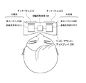
- FIG. 1 is a diagram showing a user wearing a head-mounted display 100 on the head as viewed from the front.
- FIG. 2 is a diagram illustrating a state in which a user wearing the head mounted display 100 illustrated in FIG. 1 is viewed from above.
- FIG. 3 is a diagram showing an example of the internal configuration of the head mounted display 100.
- FIG. 4 is a diagram illustrating a state in which the cursor is placed so that the center line of the line of sight and the cursor and the finger to be operated are aligned on the display image fused in the user's brain.
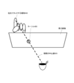
- FIG. 5 is a diagram illustrating a state where the user designates an area for displaying an image of the real world using the touch panel 315.
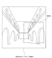
- FIG. 6 is a diagram illustrating a state in which a region 602 designated by a user operation in the virtual world image 601 displayed by the display unit 309 is replaced with a real world image.
- FIG. 7 is a diagram showing a functional configuration for the head mounted display 100 to display a part of the display area by replacing it with a real-world image.
- FIG. 8 is a diagram illustrating a rendering result V of the virtual world and an image R V corresponding to the region specified by the user.
- FIG. 9 is a diagram illustrating a real-world image I captured by the outer camera 312 and an image R I of an area corresponding to the area specified by the user.
- FIG. 10 is a diagram illustrating a display image replace the image R V of a corresponding area in the virtual world of the rendering result V in the image R I of the corresponding region of the real world.
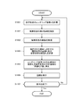
- FIG. 11 is a flowchart showing a processing procedure for the head-mounted display 100 to display a part of the display area by replacing it with a real-world image.
- FIG. 12 is a diagram showing a state in which the user moves the fingertip indicating the boundary of the area 1201 where the user wants to display the real world to expand the area 1202.
- FIG. 13 is a diagram showing a state in which the user moves the fingertip pointing the boundary of the area 1301 where the user wants to display the real world to reduce the area 1302.
- FIG. 12 is a diagram showing a state in which the user moves the fingertip pointing the boundary of the area 1301 where the user wants to display the real world to reduce the area 1302.
- FIG. 14 is a diagram illustrating a functional configuration for the head-mounted display 100 to display an image in which a three-dimensional model of an object existing in the real world is arranged in the virtual world.
- FIG. 15 is a diagram illustrating a state in which a specific object is detected in the real world.
- Figure 16 is adapted to generate a three-dimensional model M I of the predetermined range including the detected object is a diagram illustrating how to calculate a corresponding region R V of the virtual space V.
- FIG. 17 is a diagram exemplifying a rendering result obtained by calculating a three-dimensional model M M in which the three-dimensional model M I of the object is arranged in the corresponding region R V of the three-dimensional model V in the virtual world.
- FIG. 18 is a flowchart illustrating a processing procedure for the head-mounted display 100 to display an image in which a three-dimensional model of an object existing in the real world is arranged in the virtual world.
- FIG. 1 shows a front view of a user wearing a head-mounted display 100 to which the technology disclosed in this specification is applied.
- the head-mounted display 100 directly covers the user's eyes when the user wears it on the head or face, and can give an immersive feeling to the user who is viewing the image. Further, unlike the see-through type, the user wearing the head mounted display 100 cannot directly view the real world scenery. However, by installing an outer camera 312 that captures a landscape in the direction of the user's line of sight and displaying the captured image, the user indirectly views the real world landscape (that is, displays the landscape with video see-through). be able to. Of course, a virtual display image such as an AR image can be superimposed on the video see-through image. Further, since the display image cannot be seen from the outside (that is, another person), it is easy to protect privacy when displaying information.
- the head-mounted display 100 shown in FIG. 1 is a structure similar to a hat shape, and is configured to directly cover the left and right eyes of the wearing user.
- a display panel (not shown in FIG. 1) for the user to observe is disposed at a position facing the left and right eyes inside the head mounted display 100 main body.
- the display panel includes a micro display such as an organic EL element or a liquid crystal display, or a laser scanning display such as a direct retina display.
- An outer camera 312 for inputting a surrounding image is installed in the approximate center of the front surface of the head mounted display 100 main body.
- microphones 103L and 103R are installed near the left and right ends of the head-mounted display 100 main body, respectively.
- a touch panel 315 that allows a user to perform touch input using a fingertip or the like is disposed outside the head mounted display 100 main body.
- a pair of left and right touch panels 315 are provided, but a single touch panel or three or more touch panels 315 may be provided.
- FIG. 2 shows a state in which a user wearing the head mounted display 100 shown in FIG. 1 is viewed from above.
- the illustrated head mounted display 100 has left-eye and right-eye display panels 104 ⁇ / b> L and 104 ⁇ / b> R on the side facing the user's face.
- the display panels 104L and 104R are configured by a laser scanning type display such as a micro display such as an organic EL element or a liquid crystal display or a retina direct drawing display.
- a laser scanning type display such as a micro display such as an organic EL element or a liquid crystal display or a retina direct drawing display.
- virtual image optical units 101L and 101R are disposed, respectively.
- the virtual image optical units 101L and 101R respectively form enlarged virtual images of the display images on the display panels 104L and 104R on the left and right pupils of the user.
- the user will observe the enlarged left and right virtual images in the brain.
- an eye width adjustment mechanism 105 is provided between the display panel for the right eye and the display panel for the left eye.
- FIG. 3 shows an internal configuration example of the head mounted display 100. Hereinafter, each part will be described.
- the control unit 301 includes a ROM (Read Only Memory) 301A and a RAM (Random Access Memory) 301B.
- the ROM 301A stores program codes executed by the control unit 301 and various data.
- the control unit 301 executes a program loaded from the ROM 301A and the storage unit 306 (described later) to the RAM 301B, thereby starting image display control and comprehensively controlling the operation of the head mounted display 100 as a whole.
- an image display control program such as moving image reproduction, an interaction control program that enables a user who is viewing a display image to interact with the real world, and the head mounted display 100
- an image display control program such as moving image reproduction
- an interaction control program that enables a user who is viewing a display image to interact with the real world
- the head mounted display 100 Specific identification information, user attribute information of a user who uses the head mounted display 100, and the like can be given.
- the input interface (IF) unit 302 includes one or more operators (none of which are shown) such as keys, buttons, switches, etc., on which the user performs input operations, accepts user instructions via the operators, and controls the control unit 301 is output. Further, the input interface unit 302 receives a user instruction including a remote control command received by the remote control receiving unit 303 and outputs it to the control unit 301.
- operators such as keys, buttons, switches, etc.
- the input interface unit 302 receives input information such as coordinate data of the touched fingertip position. Is output to the control unit 301.
- the touch panel 315 is disposed on the back of the display image of the display unit 309 (enlarged virtual image observed through the virtual image optical unit 310) on the front surface of the main body of the head mounted display 100, the user can touch the display image with a fingertip. Touch operation can be performed as if touching.
- the status information acquisition unit 304 is a functional module that acquires status information of the head mounted display 100 main body or a user wearing the head mounted display 100.
- the state information acquisition unit 304 may be equipped with various sensors for detecting state information by itself, or an external device (for example, a user wears a part or all of these sensors).
- the status information may be acquired via a communication unit 305 (described later) from a smartphone, a wristwatch, or another multifunction terminal.
- the status information acquisition unit 304 acquires, for example, information on the position and posture of the user's head or information on the posture in order to track the user's head movement.
- the state information acquisition unit 304 is, for example, a sensor that can detect a total of nine axes including a three-axis gyro sensor, a three-axis acceleration sensor, and a three-axis geomagnetic sensor.
- the state information acquisition unit 304 may use any one or more sensors such as a GPS (Global Positioning System) sensor, a Doppler sensor, an infrared sensor, and a radio wave intensity sensor.
- the state information acquisition unit 304 acquires information provided from various infrastructures such as mobile phone base station information and PlaceEngine (registered trademark) information (electrical measurement information from a wireless LAN access point) for acquiring position and orientation information. Further, it may be used in combination.
- the state acquisition unit 304 for tracking the head movement is built in the head mounted display 100, but is configured with accessory parts attached to the head mounted display 100. It may be.
- the externally connected state acquisition unit 304 expresses the posture information of the head in the form of a rotation matrix, for example, wireless communication such as Bluetooth (registered trademark) communication, or USB (Universal Serial Bus).
- the data is transmitted to the head mounted display 100 main body via a high-speed wired interface.
- the state information acquisition unit 304 may include, for example, the user's work state (head mounted display) as the state information of the user wearing the head mounted display 100. 100 or not), user's action state (moving state such as stationary, walking, running, etc.) gesture by hand or fingertip, opening / closing state of eyelids, gaze direction, pupil size), mental state (user displays display image) The degree of excitement, excitement, wakefulness, emotion, emotion, etc.), and physiological state, such as whether they are immersed or concentrated during observation.
- the state information acquisition unit 304 acquires the state information from the user by using an outer camera 312, a wearing sensor such as a mechanical switch, an inner camera that captures the user's face, a gyro sensor, an acceleration sensor, Speed sensor, pressure sensor, temperature sensor that detects body temperature or air temperature, sweat sensor, pulse sensor, myoelectric sensor, electro-oculogram sensor, electroencephalogram sensor, exhalation sensor, gas / ion concentration sensor, etc. (Not shown) may also be provided.
- a wearing sensor such as a mechanical switch, an inner camera that captures the user's face, a gyro sensor, an acceleration sensor, Speed sensor, pressure sensor, temperature sensor that detects body temperature or air temperature, sweat sensor, pulse sensor, myoelectric sensor, electro-oculogram sensor, electroencephalogram sensor, exhalation sensor, gas / ion concentration sensor, etc. (Not shown) may also be provided.
- the environment information acquisition unit 316 is a functional module that acquires information regarding the environment surrounding the head mounted display 100 main body or a user wearing the head mounted display 100.
- Information on the environment here includes sound, air volume, temperature, atmospheric pressure, atmosphere (smoke, dense fog, electromagnetic waves (ultraviolet rays, blue light, radio waves), heat rays (infrared rays), radiation, and the like that the head mounted display 100 or the user receives.
- the environment sensor may include the above-described microphone and the outside camera 312.
- the environment information acquisition unit 316 may include an external device (for example, a part or all of these sensors).
- the environment information may be acquired via a communication unit 305 (described later) from a smartphone, a wristwatch, or other multi-function terminal worn by the user.
- the outer camera 312 is disposed, for example, in the center of the front surface of the head mounted display 100 (see FIG. 1), and can capture a surrounding image. It is assumed that the user can adjust the zoom of the outer camera 312 through an input operation via the input interface unit 302, a pupil size recognized by an inner camera, a myoelectric potential sensor, or the like or voice input. Further, by performing posture control in the pan, tilt, and roll directions of the outer camera 312 in accordance with the user's line-of-sight direction acquired by the state information acquisition unit 304, the image of the user's own eyes, that is, the user's line-of-sight direction, is obtained with the outer camera 312 Images can be taken. The captured image of the outer camera 312 can be displayed and output on the display unit 309, and the captured image can be transmitted from the communication unit 305 or stored in the storage unit 306.
- the outer camera 312 is composed of a plurality of cameras so that the three-dimensional information of the surrounding image can be acquired using the parallax information.
- shooting is performed while moving the camera using SLAM (Simultaneous Localization and Mapping) image recognition, and parallax information is calculated using a plurality of frame images that move in time (for example, (See Patent Document 3), and the three-dimensional information of the surrounding image can be acquired from the calculated parallax information.
- SLAM Simultaneous Localization and Mapping
- the outer camera 312 can acquire three-dimensional information, it can also be used as a distance sensor.
- a distance sensor made of an inexpensive device such as PSD (Position Sensitive Detector) that detects a reflection signal from an object may be used in combination with the outer camera 312.
- PSD Position Sensitive Detector
- the outer camera 312 and the distance sensor can be used to detect the body position, posture, and shape of the user wearing the head mounted display 100.
- the communication unit 305 performs communication processing with an external device, modulation / demodulation of communication signals, and encoding / decoding processing.
- external devices include a content playback device (Blu-ray disc or DVD player) that supplies viewing content when a user uses the head-mounted display 100, a multi-function terminal such as a smartphone, a game machine, and a streaming server. be able to.
- the control unit 301 transmits transmission data to the external device from the communication unit 305.
- the configuration of the communication unit 305 is arbitrary.
- the communication unit 305 can be configured according to a communication method used for transmission / reception operations with an external device that is a communication partner.
- the communication method may be either wired or wireless.
- Communication standards mentioned here include MHL (Mobile High-definition Link), USB (Universal Serial Bus), HDMI (registered trademark) Multimedia Interface, Wi-Fi (registered trademark), Bluetooth (registered trademark), and Bluetooth (registered trademark), Bluetooth (registered trademark), and Bluetooth (registered trademark), Bluetooth (registered trademark), and Bluetooth (registered trademark), Bluetooth (registered trademark), and Bluetooth (registered trademark), Bluetooth (registered trademark), and Bluetooth (registered trademark), Bluetooth (trademark) Examples include BLE (Bluetooth (registered trademark) Low Energy) communication, ultra-low power wireless communication such as ANT, and a mesh network standardized by IEEE 802.11s.
- the communication unit 305 may be a cellular radio transceiver that operates according to a standard such
- the storage unit 306 is a large-capacity storage device configured by an SSD (Solid State Drive) or the like.
- the storage unit 306 stores application programs executed by the control unit 301 and various data. For example, the user uses the head mounted display 100 to store content to be viewed in the storage unit 306.
- the image processing unit 307 further performs signal processing such as image quality correction on the image signal output from the control unit 301 and converts the image signal to a resolution that matches the screen of the display unit 309.
- the display driving unit 308 sequentially selects the pixels of the display unit 309 for each row and performs line sequential scanning, and supplies a pixel signal based on the image signal subjected to signal processing.
- the display unit 309 includes a display panel including a micro display such as an organic EL (Electro-Luminescence) element or a liquid crystal display, or a laser scanning display such as a retina direct drawing display.
- the virtual image optical unit 310 enlarges and projects the display image of the display unit 309 and causes the user to observe it as an enlarged virtual image.
- the display image output by the display unit 309 includes a content playback device (Blu-ray disc or DVD player), a multifunctional terminal such as a smartphone, a game machine, commercial content supplied from a streaming server (virtual world), and an outer camera. Examples include 312 photographed images (real world).
- the audio processing unit 313 further performs signal processing such as sound quality correction, audio amplification, and input audio signal on the audio signal output from the control unit 301. Then, the voice input / output unit 314 outputs the voice after voice processing to the outside and inputs voice from the microphone (described above).
- the head-mounted display 100 as shown in FIGS. 1 and 2 is light-shielding, that is, covers the eyes of the user who wears it.
- the display unit 309 displays moving image content such as a movie or an image expressed by computer graphics or the like.
- the virtual image optical unit 310 enlarges and projects the display image of the display unit 309, and causes the user to observe it as an enlarged virtual image having an appropriate angle of view, and reproduces a sense of reality such as watching in a movie theater, for example.
- the user can experience an immersion in the virtual world displayed on the display unit 309.
- the head-mounted display 100 is displayed in the outside world, that is, in the real world, which is captured by the outer camera 312 when a virtual world image such as a movie or computer graphics is displayed on the display unit 309.
- the images are mixed. Therefore, users can perceive the real world by interacting with the real world by looking at the real world image mixed with the virtual world image, reduce psychological resistance, and reduce real-world objects. Can avoid physical damage caused by collisions.
- the head-mounted display 100 captures a part of the area specified by the user with the outer camera 312 in the display area of the display unit 309 displaying the virtual world image. Replace and display the world image.
- the image displayed on the display unit 309 (the image observed by the user's pupil via the virtual image optical unit 310) includes information on the virtual world such as a reproduction image of commercial content, and information on the real world captured by the outer camera 312. Are combined. Therefore, the user can continuously grasp the surrounding environment (the phenomenon actually occurring in the vicinity of the user) without interrupting the state immersed in the virtual world represented by the content.
- the displayed real-world image is basically a live image taken by the outer camera 312, but may be a recorded image once stored in the storage unit 306.
- the real-world image is displayed temporarily in the area specified by the user.
- the entire display area of the display unit 309 may be returned to the virtual world image by an explicit operation in which the user cancels the designation of the area.
- the user may switch from the real world image to the virtual world image after a certain period of time has elapsed since the user specified the area, or gradually (for example, the mixing ratio of the real world image and the virtual world image). You may make it return to the image of a virtual world.
- the reason why the image of the original virtual world is restored over time is that the user no longer needs to display the real world after a certain period of time has elapsed since the user performed the operation.
- the method for designating the area in which the user displays the real world image is arbitrary.
- the user may operate a button included in the input interface unit 302 to designate an area to be replaced with the real world.
- the area to be replaced with the real world may be moved up, down, left, and right according to the operation of the cross key.
- an area corresponding to a place where the user touches the touch panel 315 with a fingertip may be replaced with the real world.
- a gesture performed by the user using a hand or the like may be photographed by the outer camera 312 so that the area indicated by the gesture is replaced with the real world.
- the touch panel 315 when the touch panel 315 is disposed on the back of the display image of the display unit 309 (enlarged virtual image observed through the virtual image optical unit 310) on the front surface of the main body of the head mounted display 100, the user can touch the display image with a fingertip. Touch operation can be performed as if touching. More specifically, when the cursor is displayed at a position corresponding to the place where the touch panel 315 is touched, as shown in FIG. 4, the center line of the line of sight (observing an enlarged virtual image fused in the user's brain) When the cursor 403 is placed so that 401 and the place 402 to be touched with the fingertip are aligned, the user can indicate a desired place on the display area as if the user touched the display image directly from the back. (For example, see Patent Document 4).
- FIG. 5 shows a state in which the user designates an area for displaying a real world image using the touch panel 315. While the display unit 309 displays only the virtual world image, the user moves the fingertip on the touch panel 315 on the back of the display unit 309 to display the real world as indicated by reference numerals 501 and 502. Specify the desired location 503.
- the area 602 designated by the user operation illustrated in FIG. 5 is replaced with a real world image captured by the outer camera 312. It shows a state.
- the image displayed on the display unit 309 is a combination of virtual world information and real world information. Therefore, the user can continuously grasp the surrounding environment (the phenomenon actually occurring in the vicinity of the user) without interrupting the state immersed in the virtual world represented by the content.
- FIG. 7 shows a functional configuration for the head mounted display 100 to display a part of the display area by replacing it with a real-world image.
- the virtual world image generation unit 701 calculates the rendering result V of the virtual world displayed on the display unit 309 based on the virtual world information stored in advance in the storage unit 306 or received from the outside by the communication unit 305, for example. .
- the real world image acquisition unit 702 acquires a real world image I around the user based on an image taken by the outer camera 312 and the like.
- the area designating unit 703 performs real-world image information on the display screen of the display unit 309 based on the operation of the touch panel 315 by the user (see FIG. 5), the operation of the input interface unit 302, the gesture input, or the like. Specifies the area to be displayed.
- Region image generating unit 704 calculates the image R I of the real world corresponding to the area specified by the area specifying unit 703, the image R V of the virtual world. Then, the image replacement section 705 synthesizes an image replacing the image R V of a corresponding area in the virtual world of the rendering result V in the image R I of the corresponding region of the real world. The synthesized image is displayed on the display unit 309.
- each of the functional blocks 701 to 705 is realized by a program executed by the control unit 301, for example, but may be configured as dedicated hardware.
- FIG. 8 illustrates a rendering result V of the virtual world and an image R V corresponding to the region specified by the user.
- FIG. 9 illustrates an image I of the real world outside the camera 312 captures an image R I of the region corresponding to the user-specified region.
- FIG. 10 illustrates a display image replace the image R V of a corresponding area in the virtual world of the rendering result V in the image R I of the corresponding region of the real world.
- FIG. 11 shows, in the form of a flowchart, a processing procedure for the head mounted display 100 to display a part of the display area by replacing it with a real-world image.
- the virtual world image generation unit 701 calculates a rendering result V of the virtual world (step S1101).
- the virtual world information is stored in advance in the storage unit 306, for example, or is prepared by being received from the outside by the communication unit 305.
- the area designating unit 703 designates a real world display area based on an operation from the user (step S1102). As described above, the user can designate a display area in the real world by operating the touch panel 315 (see FIG. 5), operating the input interface unit 302, or inputting a gesture.
- the real world image acquisition unit 702 obtains an image I around the user, that is, an image I of the real world from an image captured by the outer camera 312. Obtain (step S1103).
- the area image generating unit 704 a captured image R I of the real world corresponding to the area specified in step S1102, calculates the image R V of the virtual world (step S1104).
- the image replacement unit 705 replaces the image R V of a corresponding area in the virtual world of the rendering result V calculated in step S1101 to the image R I of the corresponding region of the real world, the image of the real world to the virtual world of the image A mixed image is generated (step S1105).
- the generated image is displayed on the display unit 309 (step S1106).
- the real world image RI is displayed in the area specified by the user.
- the entire display area of the display unit 309 may be returned to the virtual world image by an explicit operation in which the user cancels the designation of the area.
- it may be switched to the virtual world image R V when a certain time has elapsed after the user designates the area, or gradually (for example, a mixture of the real world image RI and the virtual world image R V while changing the rate) may be returned to the image R V of the virtual world.
- gradually for example, a mixture of the real world image RI and the virtual world image R V while changing the rate
- step S1107 When the display of the virtual world image is continued on the display unit 309 (No in step S1107), the process returns to step S1101, and the above-described processing is repeatedly executed.
- the display area of the real world it is updated from time to time.
- the touch panel 315 reads the position where the fingertip is moved, and the area 1201 is expanded from the area 1201 to the area 1202 as shown in FIG.
- the area 1301 can be reduced to the area 1302 as shown in FIG.
- the user can enlarge the area for displaying the real world image by the operation as shown in FIG. 12, and when the real world situation becomes insignificant, as shown in FIG.
- the region for displaying the real world image can be reduced by a simple operation, and the region for displaying the virtual world can be made wider.
- the user can interact with the real world without impairing the sense of immersion in the virtual world.
- a user wearing such a head-mounted display 100 can reduce psychological resistance to immersion in the virtual world.
- the user can reduce the risk of physical damage caused by physical movement in the real world.
- the head-mounted display 100 displays an image in which a three-dimensional model of a specific object existing in the real world is arranged in a three-dimensional virtual world.
- an image of the real world is superimposed on a part of the display image of the virtual world (like a child screen), whereas in the second embodiment, the entire display image is an image of the virtual world. It is different in that it is.
- a three-dimensional model corresponding to a real world object is displayed as an object in a virtual world image.
- the three-dimensional model is information in the real world, but the object is a three-dimensional model, and has high affinity with the display image of the virtual world.
- the real-world object mentioned here is a part of the body of the user wearing the head-mounted display 100 such as the right hand.
- a 3D model of various objects in the real world such as a specific person such as a user's acquaintance, a specific animal such as a pet, a moving object, and a stationary object may be arranged and displayed in the virtual world.
- Objects arranged in the virtual world may be fixed, or may be sequentially selectable by the user.
- the head-mounted display 100 detects an object in the real world using the outer camera 312 or a distance sensor, the head-mounted display 100 tracks the object and places the three-dimensional model in the virtual world for rendering processing.
- all the objects in the real world from the head mount display 100 within a certain distance automatically detected as an object, to be displayed by arranging the three-dimensional model M I in the virtual world Also good. For example, when a user brings a hand holding an object such as a cup close to the head-mounted display 100, it is automatically detected as an object, and is tracked while the hand is within a certain distance from the head-mounted display 100.
- the three-dimensional model M I is arranged and displayed in the virtual world. When the hand is outside the predetermined distance, no longer detected, even disappear display of the three-dimensional model M I.
- the display of three-dimensional model M I rather than extinguish instantaneously, the distance the transparency increased gradually in accordance with, or automatically be displayed in the original virtual world only. This is because it is considered that the user does not need to display an object outside a certain distance.
- an image displayed on the display unit 309 is virtual world information such as a reproduction image of commercial content and the outer camera 312. It is a combination of three-dimensional models of photographed real-world information. Therefore, the user can continuously grasp the surrounding environment (the phenomenon actually occurring in the vicinity of the user) without interrupting the state immersed in the virtual world represented by the content.
- the three-dimensional model is basically generated based on the current time difference object shown in the live image taken by the outer camera 312, but the current time difference shown in the recorded image once stored in the storage unit 306. It may be generated based on objects in the world.
- the virtual world information and the real world information are combined by two-dimensional image processing
- the virtual world information and the real world are combined by three-dimensional rendering processing.
- the functions of the real world two-dimensional display and the three-dimensional display may be combined.
- the real-world image is temporarily displayed in the area corresponding to the location where the object is detected.
- the three-dimensional model corresponding to the object may disappear from the display image of the virtual world, or the real-world object
- the three-dimensional model corresponding to the above may be gradually made transparent (for example, while changing the mixing ratio of the real world image and the virtual world image) to return the image to the original virtual world only. This is because if the object disappears, the user will no longer need a real-world display.
- the entire display area of the display unit 309 may be returned to the virtual world image by an explicit operation in which the user cancels the designation of the area.
- FIG. 14 shows a functional configuration for the head mounted display 100 to display an image in which an object existing in the real world is three-dimensionally modeled and arranged in the virtual world.
- the object detection unit 1401 detects a specific object such as a part of the user's body in the real world based on the recognition processing of the captured image of the outer camera 312 and the detection signal of the distance sensor. Further, all objects in the real world within a certain distance from the head mounted display 100 may be automatically detected as objects.
- the real world image acquisition unit 1402 acquires a real world image including an object detected by the object detection unit 1401 based on an image taken by the outer camera 312 or the like.
- the three-dimensional model calculation unit 1403 generates a three-dimensional model M I in a predetermined range including the detected object based on the detection result by the object detection unit 1401 and the real world image acquired by the real world image acquisition unit 1402. To do.
- the three-dimensional model calculation unit 1403 calculates a region R V of the virtual space V corresponding to the place where the object detection unit 1401 detects the object.
- the virtual world image generation unit 1404 calculates the three-dimensional model M M in which the three-dimensional model M I of the object is arranged in the corresponding region R V of the virtual world three-dimensional model V, and performs rendering processing.
- the rendered image is displayed on the display unit 309.
- each of the functional blocks 1401 to 1404 described above is realized by a program executed by the control unit 301, for example, but may be configured as dedicated hardware.
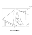
- FIG. 15 illustrates a state in which the object detection unit 1401 detects a specific object such as a part of the user's body in the real world, as indicated by reference numeral 1501.
- the outer camera 312 captures a real-world image including the object detected by the object detection unit 1401.
- the object detection unit 1401 detects a plastic bottle placed on a table and held by the user with the right hand.
- FIG. 16 illustrates a state in which the three-dimensional model calculation unit 1403 generates a three-dimensional model M I in a predetermined range including the object detected by the object detection unit 1401, as indicated by reference numeral 1601.
- the image M I for PET bottles grabbed by the user's right hand and right hand are three-dimensional modeled is generated.
- FIG. 16 illustrates a state in which the three-dimensional model calculation unit 1403 calculates the region R V of the virtual space V corresponding to the place where the object detection unit 1401 detects the object, as indicated by reference numeral 1602. ing.
- the virtual world image generation unit 1404 calculates and renders a three-dimensional model M M in which the three-dimensional model M I of the object is arranged in the corresponding region R V of the virtual world three-dimensional model V. Is illustrated.
- an image M I in which a plastic bottle grasped by the user's right hand and right hand is three-dimensionally modeled is superimposed on the three-dimensional model image of the virtual space V.
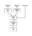
- FIG. 18 shows a processing procedure for displaying an image in which the head-mounted display 100 arranges a three-dimensional model of an object existing in the real world in the virtual world in the form of a flowchart.
- the object detection unit 1401 detects a specific object such as a part of the user's body in the real world based on the recognition processing of the captured image of the outer camera 312 and the detection signal of the distance sensor (step S1801).
- the object detection unit 1401 may automatically detect all objects in the real world within a certain distance from the head-mounted display 100. For example, when the user brings a hand holding an object such as a cup close to the head-mounted display 100, it is automatically detected as an object and is tracked while it is within a certain distance. Also, if the hand moves away from a certain distance, the object detection unit 1401 stops detecting and stops tracking.
- the real world image acquisition unit 1402 includes a real world image including an object detected by the object detection unit 1401 based on an image captured by the outer camera 312. Is acquired (step S1802).
- the three-dimensional model calculation unit 1403 is based on the detection result by the object detection unit 1401 and the real-world image acquired by the real-world image acquisition unit 1402, and the three-dimensional model M I in a predetermined range including the detected object. Is generated (step S1803).
- the three-dimensional model calculation unit 1403 calculates a region R V of the virtual space V corresponding to the place where the object detection unit 1401 detects the object (step S1804).
- the virtual world image generation unit 1404 the corresponding region R V of the three-dimensional model V of the virtual world, by calculating the 3-dimensional model M M arranged a three-dimensional model M I of the predetermined range including the object (step S1805 ) Rendering of M M which comes out in three dimensions is performed (step S1806).
- the rendered image is displayed on the display unit 309 (step S1807).
- step S1808 When the display of the virtual world image is continued on the display unit 309 (No in step S1808), the process returns to step S1801, and the above-described processing is repeatedly executed.
- step S1801 the 3D model M I is arranged in the virtual space V as the object moves in the real world.
- the region R V is updated as needed.
- the boundary may be manipulated on condition that the current position of the object overlaps the boundary between the real world three-dimensional model M I displayed on the display unit 309 and the virtual world V. Or you may transfer to the state which can operate a boundary by recognizing a user's specific gesture.
- the user can interact with the real world without impairing the sense of immersion in the virtual world.
- a user wearing such a head-mounted display 100 can reduce psychological resistance to immersion in the virtual world.
- the user can reduce the risk of physical damage caused by physical movement in the real world.
- the technology disclosed in the present specification has been described mainly with respect to an embodiment in which the technology disclosed in this specification is applied to a light-shielding head-mounted display.
- the gist of the technology disclosed in this specification is limited to this. is not.
- Various types of image display devices equipped with functions for displaying real-world images and virtual-world images such as transparent head-mounted displays, head-up displays, smartphones with cameras, and multifunction terminals Similarly, the technology disclosed in this specification can be applied.
- a display unit A real world image acquisition unit for acquiring a real world image; An area designating unit for designating an area for displaying a real-world image; Based on the designated area, an image generation unit that mixes a real-world image in a virtual image and generates an image to be displayed on the display unit; An image display device mounted on the head or face.
- the display unit is disposed at a position of the eyes of a user who wears the image display device on a head or a face, It further includes a photographing unit that photographs the user's line-of-sight direction,
- the real world image acquisition unit acquires a real world image captured by the imaging unit.
- the image display device according to (1) above.
- a virtual world image generation unit that generates an image of the virtual world; Further comprising an area image generation unit for calculating the image R V virtual world image R I of the real world corresponding to the area specifying unit specifies the area, The image generation unit generates an image by replacing the image R V of a corresponding area in the virtual world of the rendering result V in the image R I of the corresponding region of the real world, and displays on the display unit,
- the image display device according to any one of (1) and (2).
- the area designating unit designates an area for displaying an image of the real world based on a user operation.
- the image display device according to (3) above.
- the image generation unit controls a mixing ratio of real-world images based on an elapsed time after the user performs an operation of designating an area.
- the image display device according to (4) above.
- the image generation unit when the user has passed a predetermined time after performing the operation for designating an area, switches the corresponding region from the image R I of the real world image R V of the virtual world, or gradually Return to the virtual world image R V ,
- the region designating unit designates a region for displaying a real world image based on a user operation on the input unit.
- the image display device according to any one of (4) to (6).
- the input unit is a touch panel
- the area designating unit designates an area corresponding to a place where the user touches the touch panel.
- the touch panel is disposed on a back surface of the display screen of the display unit.
- the area designating unit designates an area for displaying an image of the real world based on a user's gesture operation.
- the region specifying unit changes a region for displaying a real world image in accordance with a user operation on a boundary between the real world image and the virtual world image.
- an object detection unit for detecting an object in the real world; To generate a three-dimensional model M I of the predetermined range including the object based on the real world image acquisition unit is acquired real world image, the region R V of the virtual space V corresponding to the location where detecting the object A three-dimensional model calculation unit for calculating Further comprising The image generation unit calculates a three-dimensional model M M in which the three-dimensional model M I of the object is arranged in the corresponding region R V of the three-dimensional model V in the virtual world, and performs a rendering process.
- the image display device according to any one of (1) and (2).
- the object detection unit detects a part of the user's body or a predetermined real-world object.
- the object detection unit detects an object in the real world within a certain distance from the image display device.
- the image generation unit controls a mixing ratio of real-world images based on an elapsed time after the object detection unit detects an object.
- the region specifying unit operates the boundary on condition that the current position of the object overlaps the boundary between the real world three-dimensional model M I and the virtual world V.
- the image display device according to any one of (12) to (15).
- An image display method comprising: (18) a real world image acquisition step of acquiring a real world image; An area designating step for designating an area for displaying a real-world image; A virtual world image generation step for generating a virtual world image; A region image generation step of calculating a real world image R I and a virtual world image R V corresponding to the region designated in the region designation step; An image generation step of generating an image replacing the image R I of the corresponding region image R V real world corresponding area in the virtual world of rendering result V, A display step of displaying the generated image on a display unit disposed at the position of the user's eye;
- DESCRIPTION OF SYMBOLS 100 Head mount display 101L, 101R ... Virtual image optical part 103L, 103R ... Microphone, 104L, 104R ... Display panel 105 ... Eye width adjustment mechanism 301 ... Control part, 301A ... ROM, 301B ... RAM 302 ... Input interface unit 303 ... Remote control receiving unit 304 ... Status information acquisition unit 305 ... Communication unit 306 ... Storage unit 307 ... Image processing unit 308 ... Display drive unit 309 ... Display unit 310 ... Virtual image optical unit 312 ... Outside camera 313 ... Audio processing unit, 314 ... Audio input / output unit, 315 ... Touch panel, 316 ... Environment information acquisition unit 701 ...
- Virtual world image generation unit 702 ... Real world image acquisition unit 703 ... Area designation unit, 704 ... Area image generation unit, 705 ... Image replacement unit 1401 ... Object detection unit, 1402 ... real world image acquisition unit 1403 ... 3D model calculation unit, 1404 ... virtual world image generation unit
Abstract
Description
表示部と、
現実世界の画像を取得する現実世界画像取得部と、
現実世界の画像を表示する領域を指定する領域指定部と、
前記指定された領域に基づいて、仮想画像内に現実世界の画像を混合して、前記表示部に表示する画像を生成する画像生成部と、
を具備する、頭部又は顔部に装着する画像表示装置である。 The present application has been made in consideration of the above problems, and the technology according to
A display unit;
A real world image acquisition unit for acquiring a real world image;
An area designating unit for designating an area for displaying a real-world image;
Based on the designated area, an image generation unit that mixes a real-world image in a virtual image and generates an image to be displayed on the display unit;
An image display device mounted on the head or face.
現実世界の画像を取得する現実世界画像取得ステップと、
現実世界の画像を表示する領域を指定する領域指定ステップと、
前記指定された領域に基づいて、仮想画像内に現実世界の画像を混合して画像を生成する画像生成ステップと、
生成した画像をユーザーの眼の位置に配設された表示部で表示する表示ステップと、
を有する画像表示方法である。 Further, the technology described in claim 17 of the present application is:
A real-world image acquisition step of acquiring a real-world image;
An area designating step for designating an area for displaying a real-world image;
An image generation step of generating an image by mixing a real-world image in a virtual image based on the designated region;
A display step of displaying the generated image on a display unit disposed at the position of the user's eye;
Is an image display method.
現実世界の画像を取得する現実世界画像取得ステップと、
現実世界の画像を表示する領域を指定する領域指定ステップと、
仮想世界の画像を生成する仮想世界画像生成ステップと、
前記領域指定ステップにおいて指定された領域に対応する現実世界の画像RIと仮想世界の画像RVを計算する領域画像生成ステップと、
仮想世界のレンダリング結果Vの対応領域の画像RVを現実世界の対応領域の画像RIに差し替えて画像を生成する画像生成ステップと、
生成した画像をユーザーの眼の位置に配設された表示部で表示する表示ステップと、
を有する画像表示方法である。 Further, the technique described in claim 18 of the present application is:
A real-world image acquisition step of acquiring a real-world image;
An area designating step for designating an area for displaying a real-world image;
A virtual world image generation step for generating a virtual world image;
A region image generation step of calculating a real world image R I and a virtual world image R V corresponding to the region designated in the region designation step;
An image generation step of generating an image replacing the image R I of the corresponding region image R V real world corresponding area in the virtual world of rendering result V,
A display step of displaying the generated image on a display unit disposed at the position of the user's eye;
Is an image display method.
現実世界の画像を取得する現実世界画像取得ステップと、
現実世界のオブジェクトを検出するオブジェクト検出ステップと、
検出したオブジェクトの仮想世界の3次元モデルVの対応領域RVを指定する領域指定ステップと、
前記現実世界画像取得部が取得した現実世界の画像に基づいて前記オブジェクトを含む所定の範囲の3次元モデルMIを生成するとともに、前記オブジェクトを検出した場所に対応する仮想空間Vの領域RVを計算する3次元モデル計算ステップと、
仮想世界の3次元モデルVの対応領域RVに、オブジェクトの3次元モデルMIを配置した3次元モデルMMを計算して、レンダリング処理を行なって画像を生成する画像生成ステップと、
生成した画像をユーザーの眼の位置に配設された表示部で表示する表示ステップと、を有する画像表示方法である。 Moreover, the technology described in claim 19 of the present application is:
A real-world image acquisition step of acquiring a real-world image;
An object detection step for detecting real-world objects;
A region designating step for designating a corresponding region R V of the three-dimensional model V of the detected virtual world of the object;
To generate a three-dimensional model M I of the predetermined range including the object based on the real world image acquisition unit is acquired real world image, the region R V of the virtual space V corresponding to the location where detecting the object A three-dimensional model calculation step for calculating
An image generation step of calculating a 3D model M M in which the 3D model M I of the object is arranged in the corresponding region R V of the 3D model V of the virtual world, and performing rendering processing to generate an image;
A display step of displaying the generated image on a display unit disposed at the position of the user's eye.
(1)表示部と、
現実世界の画像を取得する現実世界画像取得部と、
現実世界の画像を表示する領域を指定する領域指定部と、
前記指定された領域に基づいて、仮想画像内に現実世界の画像を混合して、前記表示部に表示する画像を生成する画像生成部と、
を具備する、頭部又は顔部に装着する画像表示装置。
(2)前記表示部は、前記画像表示装置を頭部又は顔部に装着するユーザーの眼の位置に配設され、
前記ユーザーの視線方向を撮影する撮影部をさらに備え、
前記現実世界画像取得部は、前記撮影部が撮影する現実世界の画像を取得する、
上記(1)に記載の画像表示装置。
(3)仮想世界の画像を生成する仮想世界画像生成部と、
前記領域指定部が指定した領域に対応する現実世界の画像RIと仮想世界の画像RVを計算する領域画像生成部をさらに備え、
前記画像生成部は、仮想世界のレンダリング結果Vの対応領域の画像RVを現実世界の対応領域の画像RIに差し替えて、前記表示部に表示する画像を生成する、
上記(1)又は(2)のいずれかに記載の画像表示装置。
(4)前記領域指定部は、ユーザーの操作に基づいて、現実世界の画像を表示する領域を指定する、
上記(3)に記載の画像表示装置。
(5)前記画像生成部は、ユーザーが領域を指定する操作を行なってからの経過時間に基づいて現実世界の画像の混合率を制御する、
上記(4)に記載の画像表示装置。
(6)前記画像生成部は、ユーザーが領域を指定する操作を行なってから一定時間が経過すると、前記対応領域を現実世界の画像RIから仮想世界の画像RVに切り替え、又は、徐々に仮想世界の画像RVに戻す、
上記(5)に記載の画像表示装置。
(7)ユーザーが入力操作を行なう入力部をさらに備え、
前記領域指定部は、前記入力部に対するユーザーの操作に基づいて、現実世界の画像を表示する領域を指定する、
上記(4)乃至(6)のいずれかに記載の画像表示装置。
(8)前記入力部はタッチパネルであり、
前記領域指定部は、前記タッチパネルをユーザーが触れた場所に対応する領域を指定する、
上記(7)に記載の画像表示装置。
(9)前記タッチパネルは、前記表示部の表示画面の背面に配設される、
上記(8)に記載の画像表示装置。
(10)前記領域指定部は、ユーザーのジェスチャー操作に基づいて、現実世界の画像を表示する領域を指定する、
上記(4)乃至(6)のいずれかに記載の画像表示装置。
(11)前記領域指定部は、現実世界の画像と仮想世界の画像の境界に対するユーザーの操作に応じて、現実世界の画像を表示する領域を変更する、
上記(4)乃至(6)のいずれかに記載の画像表示装置。
(12)現実世界のオブジェクトを検出するオブジェクト検出部と、
前記現実世界画像取得部が取得した現実世界の画像に基づいて前記オブジェクトを含む所定の範囲の3次元モデルMIを生成するとともに、前記オブジェクトを検出した場所に対応する仮想空間Vの領域RVを計算する3次元モデル計算部と、
をさらに備え、
前記画像生成部は、仮想世界の3次元モデルVの対応領域RVに、オブジェクトの3次元モデルMIを配置した3次元モデルMMを計算して、レンダリング処理を行なう、
上記(1)又は(2)のいずれかに記載の画像表示装置。
(13)前記オブジェクト検出部は、ユーザーの身体の一部、又は、あらかじめ決められた現実世界の物体を検出する、
上記(12)に記載の画像表示装置。
(14)前記オブジェクト検出部は、前記画像表示装置から一定距離以内にある現実世界の物体を検出する、
上記(12)に記載の画像表示装置。
(15)前記画像生成部は、前記オブジェクト検出部がオブジェクトを検出してからの経過時間に基づいて現実世界の画像の混合率を制御する、
上記(12)乃至(14)のいずれかに記載の画像表示装置。
(16)前記領域指定部は、オブジェクトの現在位置が現実世界の3次元モデルMIと仮想世界Vの境界に重なることを条件として、境界を操作する、
上記(12)乃至(15)のいずれかに記載の画像表示装置。
(17)現実世界の画像を取得する現実世界画像取得ステップと、
現実世界の画像を表示する領域を指定する領域指定ステップと、
前記指定された領域に基づいて、仮想画像内に現実世界の画像を混合して画像を生成する画像生成ステップと、
生成した画像をユーザーの眼の位置に配設された表示部で表示する表示ステップと、
を有する画像表示方法。
(18)現実世界の画像を取得する現実世界画像取得ステップと、
現実世界の画像を表示する領域を指定する領域指定ステップと、
仮想世界の画像を生成する仮想世界画像生成ステップと、
前記領域指定ステップにおいて指定された領域に対応する現実世界の画像RIと仮想世界の画像RVを計算する領域画像生成ステップと、
仮想世界のレンダリング結果Vの対応領域の画像RVを現実世界の対応領域の画像RIに差し替えて画像を生成する画像生成ステップと、
生成した画像をユーザーの眼の位置に配設された表示部で表示する表示ステップと、
を有する画像表示方法。
(19)現実世界の画像を取得する現実世界画像取得ステップと、
現実世界のオブジェクトを検出するオブジェクト検出ステップと、
検出したオブジェクトの仮想世界の3次元モデルVの対応領域RVを指定する領域指定ステップと、
前記現実世界画像取得部が取得した現実世界の画像に基づいて前記オブジェクトを含む所定の範囲の3次元モデルMIを生成するとともに、前記オブジェクトを検出した場所に対応する仮想空間Vの領域RVを計算する3次元モデル計算ステップと、
仮想世界の3次元モデルVの対応領域RVに、オブジェクトの3次元モデルMIを配置した3次元モデルMMを計算して、レンダリング処理を行なって画像を生成する画像生成ステップと、
生成した画像をユーザーの眼の位置に配設された表示部で表示する表示ステップと、を有する画像表示方法。 Note that the technology disclosed in the present specification can also be configured as follows.
(1) a display unit;
A real world image acquisition unit for acquiring a real world image;
An area designating unit for designating an area for displaying a real-world image;
Based on the designated area, an image generation unit that mixes a real-world image in a virtual image and generates an image to be displayed on the display unit;
An image display device mounted on the head or face.
(2) The display unit is disposed at a position of the eyes of a user who wears the image display device on a head or a face,
It further includes a photographing unit that photographs the user's line-of-sight direction,
The real world image acquisition unit acquires a real world image captured by the imaging unit.
The image display device according to (1) above.
(3) a virtual world image generation unit that generates an image of the virtual world;
Further comprising an area image generation unit for calculating the image R V virtual world image R I of the real world corresponding to the area specifying unit specifies the area,
The image generation unit generates an image by replacing the image R V of a corresponding area in the virtual world of the rendering result V in the image R I of the corresponding region of the real world, and displays on the display unit,
The image display device according to any one of (1) and (2).
(4) The area designating unit designates an area for displaying an image of the real world based on a user operation.
The image display device according to (3) above.
(5) The image generation unit controls a mixing ratio of real-world images based on an elapsed time after the user performs an operation of designating an area.
The image display device according to (4) above.
(6) the image generation unit, when the user has passed a predetermined time after performing the operation for designating an area, switches the corresponding region from the image R I of the real world image R V of the virtual world, or gradually Return to the virtual world image R V ,
The image display device according to (5) above.
(7) It further includes an input unit for a user to perform an input operation,
The region designating unit designates a region for displaying a real world image based on a user operation on the input unit.
The image display device according to any one of (4) to (6).
(8) The input unit is a touch panel,
The area designating unit designates an area corresponding to a place where the user touches the touch panel.
The image display device according to (7) above.
(9) The touch panel is disposed on a back surface of the display screen of the display unit.
The image display device according to (8) above.
(10) The area designating unit designates an area for displaying an image of the real world based on a user's gesture operation.
The image display device according to any one of (4) to (6).
(11) The region specifying unit changes a region for displaying a real world image in accordance with a user operation on a boundary between the real world image and the virtual world image.
The image display device according to any one of (4) to (6).
(12) an object detection unit for detecting an object in the real world;
To generate a three-dimensional model M I of the predetermined range including the object based on the real world image acquisition unit is acquired real world image, the region R V of the virtual space V corresponding to the location where detecting the object A three-dimensional model calculation unit for calculating
Further comprising
The image generation unit calculates a three-dimensional model M M in which the three-dimensional model M I of the object is arranged in the corresponding region R V of the three-dimensional model V in the virtual world, and performs a rendering process.
The image display device according to any one of (1) and (2).
(13) The object detection unit detects a part of the user's body or a predetermined real-world object.
The image display device according to (12) above.
(14) The object detection unit detects an object in the real world within a certain distance from the image display device.
The image display device according to (12) above.
(15) The image generation unit controls a mixing ratio of real-world images based on an elapsed time after the object detection unit detects an object.
The image display device according to any one of (12) to (14).
(16) The region specifying unit operates the boundary on condition that the current position of the object overlaps the boundary between the real world three-dimensional model M I and the virtual world V.
The image display device according to any one of (12) to (15).
(17) a real world image acquisition step of acquiring a real world image;
An area designating step for designating an area for displaying a real-world image;
An image generation step of generating an image by mixing a real-world image in a virtual image based on the designated region;
A display step of displaying the generated image on a display unit disposed at the position of the user's eye;
An image display method comprising:
(18) a real world image acquisition step of acquiring a real world image;
An area designating step for designating an area for displaying a real-world image;
A virtual world image generation step for generating a virtual world image;
A region image generation step of calculating a real world image R I and a virtual world image R V corresponding to the region designated in the region designation step;
An image generation step of generating an image replacing the image R I of the corresponding region image R V real world corresponding area in the virtual world of rendering result V,
A display step of displaying the generated image on a display unit disposed at the position of the user's eye;
An image display method comprising:
(19) a real world image acquisition step of acquiring a real world image;
An object detection step for detecting real-world objects;
A region designating step for designating a corresponding region R V of the three-dimensional model V of the detected virtual world of the object;
To generate a three-dimensional model M I of the predetermined range including the object based on the real world image acquisition unit is acquired real world image, the region R V of the virtual space V corresponding to the location where detecting the object A three-dimensional model calculation step for calculating
An image generation step of calculating a 3D model M M in which the 3D model M I of the object is arranged in the corresponding region R V of the 3D model V of the virtual world, and performing rendering processing to generate an image;
A display step of displaying the generated image on a display unit disposed at the position of the user's eye.
101L、101R…虚像光学部
103L、103R…マイクロフォン、104L、104R…表示パネル
105…眼幅調整機構
301…制御部、301A…ROM、301B…RAM
302…入力インターフェース部、303…リモコン受信部
304…状態情報取得部、305…通信部、306…記憶部
307…画像処理部、308…表示駆動部
309…表示部、310…虚像光学部、312…外側カメラ
313…音声処理部、314…音声入出力部、
315…タッチパネル、316…環境情報取得部
701…仮想世界画像生成部、702…現実世界画像取得部
703…領域指定部、704…領域画像生成部、705…画像差し替え部
1401…オブジェクト検出部、1402…現実世界画像取得部
1403…3次元モデル計算部、1404…仮想世界画像生成部 DESCRIPTION OF SYMBOLS 100 ... Head mount display 101L, 101R ... Virtual image optical part 103L, 103R ... Microphone, 104L, 104R ... Display panel 105 ... Eye width adjustment mechanism 301 ... Control part, 301A ... ROM, 301B ... RAM
302 ... Input interface unit 303 ... Remote
315 ... Touch panel, 316 ... Environment
Claims (19)
- 表示部と、
現実世界の画像を取得する現実世界画像取得部と、
現実世界の画像を表示する領域を指定する領域指定部と、
前記指定された領域に基づいて、仮想画像内に現実世界の画像を混合して、前記表示部に表示する画像を生成する画像生成部と、
を具備する、頭部又は顔部に装着する画像表示装置。 A display unit;
A real world image acquisition unit for acquiring a real world image;
An area designating unit for designating an area for displaying a real-world image;
Based on the designated area, an image generation unit that mixes a real-world image in a virtual image and generates an image to be displayed on the display unit;
An image display device mounted on the head or face. - 前記表示部は、前記画像表示装置を頭部又は顔部に装着するユーザーの眼の位置に配設され、
前記ユーザーの視線方向を撮影する撮影部をさらに備え、
前記現実世界画像取得部は、前記撮影部が撮影する現実世界の画像を取得する、
請求項1に記載の画像表示装置。 The display unit is disposed at a position of a user's eye wearing the image display device on a head or a face,
It further includes a photographing unit that photographs the user's line-of-sight direction,
The real world image acquisition unit acquires a real world image captured by the imaging unit.
The image display device according to claim 1. - 仮想世界の画像を生成する仮想世界画像生成部と、
前記領域指定部が指定した領域に対応する現実世界の画像RIと仮想世界の画像RVを計算する領域画像生成部をさらに備え、
前記画像生成部は、仮想世界のレンダリング結果Vの対応領域の画像RVを現実世界の対応領域の画像RIに差し替えて、前記表示部に表示する画像を生成する、
請求項1に記載の画像表示装置。 A virtual world image generation unit for generating an image of the virtual world;
Further comprising an area image generation unit for calculating the image R V virtual world image R I of the real world corresponding to the area specifying unit specifies the area,
The image generation unit generates an image by replacing the image R V of a corresponding area in the virtual world of the rendering result V in the image R I of the corresponding region of the real world, and displays on the display unit,
The image display device according to claim 1. - 前記領域指定部は、ユーザーの操作に基づいて、現実世界の画像を表示する領域を指定する、
請求項3に記載の画像表示装置。 The area designating unit designates an area for displaying a real world image based on a user operation.
The image display device according to claim 3. - 前記画像生成部は、ユーザーが領域を指定する操作を行なってからの経過時間に基づいて現実世界の画像の混合率を制御する、
請求項4に記載の画像表示装置。 The image generation unit controls a mixing ratio of real-world images based on an elapsed time after the user performs an operation of designating an area.
The image display device according to claim 4. - 前記画像生成部は、ユーザーが領域を指定する操作を行なってから一定時間が経過すると、前記対応領域を現実世界の画像RIから仮想世界の画像RVに切り替え、又は、徐々に仮想世界の画像RVに戻す、
請求項5に記載の画像表示装置。 The image generation unit, when the user has passed a predetermined time after performing the operation for designating an area, the switching of the corresponding region from the image R I of the real world image R V of the virtual world, or gradually virtual world Return to image R V
The image display device according to claim 5. - ユーザーが入力操作を行なう入力部をさらに備え、
前記領域指定部は、前記入力部に対するユーザーの操作に基づいて、現実世界の画像を表示する領域を指定する、
請求項4に記載の画像表示装置。 It further includes an input unit for a user to perform an input operation,
The region designating unit designates a region for displaying a real world image based on a user operation on the input unit.
The image display device according to claim 4. - 前記入力部はタッチパネルであり、
前記領域指定部は、前記タッチパネルをユーザーが触れた場所に対応する領域を指定する、
請求項7に記載の画像表示装置。 The input unit is a touch panel,
The area designating unit designates an area corresponding to a place where the user touches the touch panel.
The image display device according to claim 7. - 前記タッチパネルは、前記表示部の表示画面の背面に配設される、
請求項8に記載の画像表示装置。 The touch panel is disposed on the back of the display screen of the display unit.
The image display device according to claim 8. - 前記領域指定部は、ユーザーのジェスチャー操作に基づいて、現実世界の画像を表示する領域を指定する、
請求項4に記載の画像表示装置。 The region designating unit designates a region for displaying a real world image based on a user's gesture operation.
The image display device according to claim 4. - 前記領域指定部は、現実世界の画像と仮想世界の画像の境界に対するユーザーの操作に応じて、現実世界の画像を表示する領域を変更する、
請求項4に記載の画像表示装置。 The region specifying unit changes a region for displaying a real world image in accordance with a user operation on a boundary between the real world image and the virtual world image.
The image display device according to claim 4. - 現実世界のオブジェクトを検出するオブジェクト検出部と、
前記現実世界画像取得部が取得した現実世界の画像に基づいて前記オブジェクトを含む所定の範囲の3次元モデルMIを生成するとともに、前記オブジェクトを検出した場所に対応する仮想空間Vの領域RVを計算する3次元モデル計算部と、
をさらに備え、
前記画像生成部は、仮想世界の3次元モデルVの対応領域RVに、オブジェクトの3次元モデルMIを配置した3次元モデルMMを計算して、レンダリング処理を行なう、
請求項1に記載の画像表示装置。 An object detector for detecting real-world objects;
To generate a three-dimensional model M I of the predetermined range including the object based on the real world image acquisition unit is acquired real world image, the region R V of the virtual space V corresponding to the location where detecting the object A three-dimensional model calculation unit for calculating
Further comprising
The image generation unit calculates a three-dimensional model M M in which the three-dimensional model M I of the object is arranged in the corresponding region R V of the three-dimensional model V in the virtual world, and performs a rendering process.
The image display device according to claim 1. - 前記オブジェクト検出部は、ユーザーの身体の一部、又は、あらかじめ決められた現実世界の物体を検出する、
請求項12に記載の画像表示装置。 The object detection unit detects a part of the user's body or a predetermined real world object.
The image display device according to claim 12. - 前記オブジェクト検出部は、前記画像表示装置から一定距離以内にある現実世界の物体を検出する、
請求項12に記載の画像表示装置。 The object detection unit detects a real-world object within a certain distance from the image display device;
The image display device according to claim 12. - 前記画像生成部は、前記オブジェクト検出部がオブジェクトを検出してからの経過時間に基づいて現実世界の画像の混合率を制御する、
請求項12に記載の画像表示装置。 The image generation unit controls a mixing ratio of real-world images based on an elapsed time after the object detection unit detects an object.
The image display device according to claim 12. - 前記領域指定部は、オブジェクトの現在位置が現実世界の3次元モデルMIと仮想世界Vの境界に重なることを条件として、境界を操作する、
請求項12に記載の画像表示装置。 The region designation unit, on condition that the current position of the object overlaps the boundaries of the three-dimensional model M I and the virtual world V the real world, to operate the boundary,
The image display device according to claim 12. - 現実世界の画像を取得する現実世界画像取得ステップと、
現実世界の画像を表示する領域を指定する領域指定ステップと、
前記指定された領域に基づいて、仮想画像内に現実世界の画像を混合して画像を生成する画像生成ステップと、
生成した画像をユーザーの眼の位置に配設された表示部で表示する表示ステップと、
を有する画像表示方法。 A real-world image acquisition step of acquiring a real-world image;
An area designating step for designating an area for displaying a real-world image;
An image generation step of generating an image by mixing a real-world image in a virtual image based on the designated region;
A display step of displaying the generated image on a display unit disposed at the position of the user's eye;
An image display method comprising: - 現実世界の画像を取得する現実世界画像取得ステップと、
現実世界の画像を表示する領域を指定する領域指定ステップと、
仮想世界の画像を生成する仮想世界画像生成ステップと、
前記領域指定ステップにおいて指定された領域に対応する現実世界の画像RIと仮想世界の画像RVを計算する領域画像生成ステップと、
仮想世界のレンダリング結果Vの対応領域の画像RVを現実世界の対応領域の画像RIに差し替えて画像を生成する画像生成ステップと、
生成した画像をユーザーの眼の位置に配設された表示部で表示する表示ステップと、
を有する画像表示方法。 A real-world image acquisition step of acquiring a real-world image;
An area designating step for designating an area for displaying a real-world image;
A virtual world image generation step for generating a virtual world image;
A region image generation step of calculating a real world image R I and a virtual world image R V corresponding to the region designated in the region designation step;
An image generation step of generating an image replacing the image R I of the corresponding region image R V real world corresponding area in the virtual world of rendering result V,
A display step of displaying the generated image on a display unit disposed at the position of the user's eye;
An image display method comprising: - 現実世界の画像を取得する現実世界画像取得ステップと、
現実世界のオブジェクトを検出するオブジェクト検出ステップと、
検出したオブジェクトの仮想世界の3次元モデルVの対応領域RVを指定する領域指定ステップと、
前記現実世界画像取得部が取得した現実世界の画像に基づいて前記オブジェクトを含む所定の範囲の3次元モデルMIを生成するとともに、前記オブジェクトを検出した場所に対応する仮想空間Vの領域RVを計算する3次元モデル計算ステップと、
仮想世界の3次元モデルVの対応領域RVに、オブジェクトの3次元モデルMIを配置した3次元モデルMMを計算して、レンダリング処理を行なって画像を生成する画像生成ステップと、
生成した画像をユーザーの眼の位置に配設された表示部で表示する表示ステップと、
を有する画像表示方法。 A real-world image acquisition step of acquiring a real-world image;
An object detection step for detecting real-world objects;
A region designating step for designating a corresponding region R V of the three-dimensional model V of the detected virtual world of the object;
To generate a three-dimensional model M I of the predetermined range including the object based on the real world image acquisition unit is acquired real world image, the region R V of the virtual space V corresponding to the location where detecting the object A three-dimensional model calculation step for calculating
An image generation step of calculating a 3D model M M in which the 3D model M I of the object is arranged in the corresponding region R V of the 3D model V of the virtual world, and performing rendering processing to generate an image;
A display step of displaying the generated image on a display unit disposed at the position of the user's eye;
An image display method comprising:
Priority Applications (6)
| Application Number | Priority Date | Filing Date | Title |
|---|---|---|---|
| KR1020167013247A KR102332326B1 (en) | 2014-01-23 | 2014-11-11 | Image display device and image display method |
| JP2015558739A JP6524917B2 (en) | 2014-01-23 | 2014-11-11 | Image display apparatus and image display method |
| EP14879372.2A EP3098689B1 (en) | 2014-01-23 | 2014-11-11 | Image display device and image display method |
| US15/038,950 US10134189B2 (en) | 2014-01-23 | 2014-11-11 | Image display device and image display method |
| EP18184698.1A EP3410264B1 (en) | 2014-01-23 | 2014-11-11 | Image display device and image display method |
| CN201480064167.2A CN105992986B (en) | 2014-01-23 | 2014-11-11 | Image display device and image display method |
Applications Claiming Priority (2)
| Application Number | Priority Date | Filing Date | Title |
|---|---|---|---|
| JP2014-010582 | 2014-01-23 | ||
| JP2014010582 | 2014-01-23 |
Publications (1)
| Publication Number | Publication Date |
|---|---|
| WO2015111283A1 true WO2015111283A1 (en) | 2015-07-30 |
Family
ID=53681105
Family Applications (1)
| Application Number | Title | Priority Date | Filing Date |
|---|---|---|---|
| PCT/JP2014/079812 WO2015111283A1 (en) | 2014-01-23 | 2014-11-11 | Image display device and image display method |
Country Status (6)
| Country | Link |
|---|---|
| US (1) | US10134189B2 (en) |
| EP (2) | EP3098689B1 (en) |
| JP (1) | JP6524917B2 (en) |
| KR (1) | KR102332326B1 (en) |
| CN (2) | CN109828671B (en) |
| WO (1) | WO2015111283A1 (en) |
Cited By (16)
| Publication number | Priority date | Publication date | Assignee | Title |
|---|---|---|---|---|
| CN106200881A (en) * | 2016-06-29 | 2016-12-07 | 乐视控股(北京)有限公司 | A kind of method for exhibiting data and device and virtual reality device |
| CN106383578A (en) * | 2016-09-13 | 2017-02-08 | 网易(杭州)网络有限公司 | Virtual reality system, and virtual reality interaction apparatus and method |
| CN106484085A (en) * | 2015-08-31 | 2017-03-08 | 北京三星通信技术研究有限公司 | Method and its head mounted display of real-world object is shown in head mounted display |
| WO2017039308A1 (en) * | 2015-08-31 | 2017-03-09 | Samsung Electronics Co., Ltd. | Virtual reality display apparatus and display method thereof |
| JP2017528834A (en) * | 2014-09-11 | 2017-09-28 | ノキア テクノロジーズ オサケユイチア | Method, apparatus and computer program for displaying images |
| WO2017189699A1 (en) * | 2016-04-27 | 2017-11-02 | Rovi Guides, Inc. | Methods and systems for displaying additional content on a heads up display displaying a virtual reality environment |
| US9851792B2 (en) | 2016-04-27 | 2017-12-26 | Rovi Guides, Inc. | Methods and systems for displaying additional content on a heads up display displaying a virtual reality environment |
| US10025376B2 (en) | 2016-04-27 | 2018-07-17 | Rovi Guides, Inc. | Methods and systems for displaying additional content on a heads up display displaying a virtual reality environment |
| CN108463839A (en) * | 2016-01-20 | 2018-08-28 | 索尼互动娱乐股份有限公司 | Information processing unit and users' guidebook rendering method |
| EP3438953A4 (en) * | 2016-03-31 | 2019-04-10 | Sony Corporation | Information processing device |
| WO2019130991A1 (en) * | 2017-12-26 | 2019-07-04 | 株式会社Nttドコモ | Information processing device |
| JP2019527881A (en) * | 2016-06-30 | 2019-10-03 | 株式会社ソニー・インタラクティブエンタテインメント | Virtual reality scene changing method and computer-readable storage medium |
| WO2020054760A1 (en) * | 2018-09-12 | 2020-03-19 | 株式会社アルファコード | Image display control device and program for controlling image display |
| JP2020520494A (en) * | 2017-05-04 | 2020-07-09 | ソニー インタラクティブ エンタテインメント ヨーロッパ リミテッド | Head mounted display and method |
| JPWO2021048985A1 (en) * | 2019-09-12 | 2021-03-18 | ||
| JP2021068195A (en) * | 2019-10-24 | 2021-04-30 | 克己 横道 | Information processing system, information processing method, and program |
Families Citing this family (33)
| Publication number | Priority date | Publication date | Assignee | Title |
|---|---|---|---|---|
| JP6138566B2 (en) * | 2013-04-24 | 2017-05-31 | 川崎重工業株式会社 | Component mounting work support system and component mounting method |
| JP6340301B2 (en) * | 2014-10-22 | 2018-06-06 | 株式会社ソニー・インタラクティブエンタテインメント | Head mounted display, portable information terminal, image processing apparatus, display control program, display control method, and display system |
| JP6618260B2 (en) * | 2015-02-19 | 2019-12-11 | キヤノン株式会社 | Information processing apparatus, information processing method, and program |
| CN105659146A (en) * | 2015-05-29 | 2016-06-08 | 深圳市柔宇科技有限公司 | Method for display adjustment and head-mounted type display device |
| JP6232649B2 (en) * | 2016-02-18 | 2017-11-22 | 国立大学法人名古屋大学 | Virtual space display system |
| US10642345B2 (en) * | 2016-10-18 | 2020-05-05 | Raytheon Company | Avionics maintenance training |
| US20190335115A1 (en) * | 2016-11-29 | 2019-10-31 | Sharp Kabushiki Kaisha | Display control device, head-mounted display, and control program |
| CN106774869B (en) * | 2016-12-08 | 2020-05-19 | 广州大西洲科技有限公司 | Method and device for realizing virtual reality and virtual reality helmet |
| WO2018112838A1 (en) * | 2016-12-22 | 2018-06-28 | 深圳市柔宇科技有限公司 | Head-mounted display apparatus, and visual-aid providing method thereof |
| US11368664B2 (en) * | 2017-01-20 | 2022-06-21 | Sony Corporation | Information processing apparatus, information processing method, and program |
| WO2018176235A1 (en) * | 2017-03-28 | 2018-10-04 | 深圳市柔宇科技有限公司 | Head-mounted display device and display switching method therefor |
| CN107172414A (en) * | 2017-04-20 | 2017-09-15 | 北京安云世纪科技有限公司 | A kind of method of virtual reality head-mounted display equipment and its processing information |
| CN107179876B (en) * | 2017-06-30 | 2023-08-25 | 吴少乔 | Man-machine interaction device based on virtual reality system |
| KR102077665B1 (en) * | 2017-09-26 | 2020-04-07 | 에이케이엔코리아 주식회사 | Virtual movile device implementing system and control method for the same in mixed reality |
| CN111279292B (en) | 2017-09-29 | 2022-06-14 | 苹果公司 | Detecting physical boundaries |
| EP3692721A1 (en) * | 2017-10-04 | 2020-08-12 | VID SCALE, Inc. | Customized 360-degree media viewing |
| DE102018207653A1 (en) * | 2018-05-16 | 2019-11-21 | Siemens Aktiengesellschaft | Display device for displaying virtual reality with a touch-sensitive operating unit; Display system; operating system |
| US20190385372A1 (en) * | 2018-06-15 | 2019-12-19 | Microsoft Technology Licensing, Llc | Positioning a virtual reality passthrough region at a known distance |
| US10600246B2 (en) * | 2018-06-15 | 2020-03-24 | Microsoft Technology Licensing, Llc | Pinning virtual reality passthrough regions to real-world locations |
| US10520739B1 (en) * | 2018-07-11 | 2019-12-31 | Valve Corporation | Dynamic panel masking |
| CN110163977B (en) * | 2018-07-13 | 2024-04-12 | 腾讯数码(天津)有限公司 | Virtual channel rendering method and device in multi-world virtual scene |
| US10776954B2 (en) | 2018-10-08 | 2020-09-15 | Microsoft Technology Licensing, Llc | Real-world anchor in a virtual-reality environment |
| US20200111256A1 (en) * | 2018-10-08 | 2020-04-09 | Microsoft Technology Licensing, Llc | Real-world anchor in a virtual-reality environment |
| KR102145852B1 (en) * | 2018-12-14 | 2020-08-19 | (주)이머시브캐스트 | Camera-based mixed reality glass apparatus and mixed reality display method |
| DE102019135676A1 (en) * | 2018-12-26 | 2020-07-02 | Htc Corporation | OBJECT TRACKING SYSTEM AND OBJECT TRACKING PROCEDURE |
| US11064255B2 (en) * | 2019-01-30 | 2021-07-13 | Oohms Ny Llc | System and method of tablet-based distribution of digital media content |
| US11265487B2 (en) | 2019-06-05 | 2022-03-01 | Mediatek Inc. | Camera view synthesis on head-mounted display for virtual reality and augmented reality |
| US11842449B2 (en) * | 2019-09-26 | 2023-12-12 | Apple Inc. | Presenting an environment based on user movement |
| JP7127659B2 (en) | 2020-02-07 | 2022-08-30 | カシオ計算機株式会社 | Information processing device, virtual/reality synthesis system, method for generating learned model, method for executing information processing device, program |
| EP3926588A1 (en) | 2020-06-19 | 2021-12-22 | Alpine Electronics, Inc. | Image displaying apparatus and method of displaying image data on a vr display device, particularly disposed in a vehicle |
| KR102543899B1 (en) * | 2020-08-27 | 2023-06-20 | 네이버랩스 주식회사 | Head up display and control method thereof |
| US11595636B1 (en) * | 2021-08-23 | 2023-02-28 | At&T Intellectual Property I, L.P. | Enhanced emotive engagement with volumetric content |
| US11960082B2 (en) | 2022-07-13 | 2024-04-16 | Htc Corporation | Virtual reality system and object detection method applicable to virtual reality system |
Citations (6)
| Publication number | Priority date | Publication date | Assignee | Title |
|---|---|---|---|---|
| JP2008096868A (en) * | 2006-10-16 | 2008-04-24 | Sony Corp | Imaging display device, and imaging display method |
| JP2008304268A (en) | 2007-06-06 | 2008-12-18 | Sony Corp | Information processor, information processing method, and computer program |
| JP2012042654A (en) | 2010-08-18 | 2012-03-01 | Sony Corp | Display device |
| JP2012141461A (en) | 2010-12-29 | 2012-07-26 | Sony Corp | Head mount display |
| JP2013200325A (en) * | 2012-03-23 | 2013-10-03 | Sony Corp | Head-mounted display |
| JP2013258573A (en) | 2012-06-13 | 2013-12-26 | Sony Corp | Head-mounted video display device |
Family Cites Families (12)
| Publication number | Priority date | Publication date | Assignee | Title |
|---|---|---|---|---|
| GB2377147A (en) * | 2001-06-27 | 2002-12-31 | Nokia Corp | A virtual reality user interface |
| JP4136420B2 (en) * | 2002-03-29 | 2008-08-20 | キヤノン株式会社 | Information processing method and apparatus |
| JP4434890B2 (en) * | 2004-09-06 | 2010-03-17 | キヤノン株式会社 | Image composition method and apparatus |
| JP4724476B2 (en) * | 2004-09-07 | 2011-07-13 | キヤノン株式会社 | Information processing method and apparatus |
| US20060050070A1 (en) * | 2004-09-07 | 2006-03-09 | Canon Kabushiki Kaisha | Information processing apparatus and method for presenting image combined with virtual image |
| US8964298B2 (en) * | 2010-02-28 | 2015-02-24 | Microsoft Corporation | Video display modification based on sensor input for a see-through near-to-eye display |
| US20120050140A1 (en) * | 2010-08-25 | 2012-03-01 | Border John N | Head-mounted display control |
| US20120113223A1 (en) * | 2010-11-05 | 2012-05-10 | Microsoft Corporation | User Interaction in Augmented Reality |
| KR20130067450A (en) * | 2011-12-14 | 2013-06-24 | 한국전자통신연구원 | Field applied safety helmet apparatus for ar-based of maintenance and method for providing its application service |
| US9116666B2 (en) * | 2012-06-01 | 2015-08-25 | Microsoft Technology Licensing, Llc | Gesture based region identification for holograms |
| JP5580855B2 (en) * | 2012-06-12 | 2014-08-27 | 株式会社ソニー・コンピュータエンタテインメント | Obstacle avoidance device and obstacle avoidance method |
| CN103489214A (en) * | 2013-09-10 | 2014-01-01 | 北京邮电大学 | Virtual reality occlusion handling method, based on virtual model pretreatment, in augmented reality system |
-
2014
- 2014-11-11 WO PCT/JP2014/079812 patent/WO2015111283A1/en active Application Filing
- 2014-11-11 CN CN201910107486.1A patent/CN109828671B/en active Active
- 2014-11-11 EP EP14879372.2A patent/EP3098689B1/en active Active
- 2014-11-11 EP EP18184698.1A patent/EP3410264B1/en active Active
- 2014-11-11 US US15/038,950 patent/US10134189B2/en active Active
- 2014-11-11 KR KR1020167013247A patent/KR102332326B1/en active IP Right Grant
- 2014-11-11 JP JP2015558739A patent/JP6524917B2/en active Active
- 2014-11-11 CN CN201480064167.2A patent/CN105992986B/en active Active
Patent Citations (6)
| Publication number | Priority date | Publication date | Assignee | Title |
|---|---|---|---|---|
| JP2008096868A (en) * | 2006-10-16 | 2008-04-24 | Sony Corp | Imaging display device, and imaging display method |
| JP2008304268A (en) | 2007-06-06 | 2008-12-18 | Sony Corp | Information processor, information processing method, and computer program |
| JP2012042654A (en) | 2010-08-18 | 2012-03-01 | Sony Corp | Display device |
| JP2012141461A (en) | 2010-12-29 | 2012-07-26 | Sony Corp | Head mount display |
| JP2013200325A (en) * | 2012-03-23 | 2013-10-03 | Sony Corp | Head-mounted display |
| JP2013258573A (en) | 2012-06-13 | 2013-12-26 | Sony Corp | Head-mounted video display device |
Non-Patent Citations (1)
| Title |
|---|
| See also references of EP3098689A4 |
Cited By (39)
| Publication number | Priority date | Publication date | Assignee | Title |
|---|---|---|---|---|
| JP2017528834A (en) * | 2014-09-11 | 2017-09-28 | ノキア テクノロジーズ オサケユイチア | Method, apparatus and computer program for displaying images |
| US10916057B2 (en) | 2014-09-11 | 2021-02-09 | Nokia Technologies Oy | Method, apparatus and computer program for displaying an image of a real world object in a virtual reality enviroment |
| CN110275619A (en) * | 2015-08-31 | 2019-09-24 | 北京三星通信技术研究有限公司 | The method and its head-mounted display of real-world object are shown in head-mounted display |
| WO2017039308A1 (en) * | 2015-08-31 | 2017-03-09 | Samsung Electronics Co., Ltd. | Virtual reality display apparatus and display method thereof |
| CN106484085A (en) * | 2015-08-31 | 2017-03-08 | 北京三星通信技术研究有限公司 | Method and its head mounted display of real-world object is shown in head mounted display |
| EP3281058A4 (en) * | 2015-08-31 | 2018-04-11 | Samsung Electronics Co., Ltd. | Virtual reality display apparatus and display method thereof |
| CN106484085B (en) * | 2015-08-31 | 2019-07-23 | 北京三星通信技术研究有限公司 | The method and its head-mounted display of real-world object are shown in head-mounted display |
| US11865448B2 (en) | 2016-01-20 | 2024-01-09 | Sony Interactive Entertainment Inc. | Information processing apparatus and user guide presentation method |
| US10974148B2 (en) | 2016-01-20 | 2021-04-13 | Sony Interactive Entertainment Inc. | Information processing apparatus and user guide presentation method |
| US11484792B2 (en) | 2016-01-20 | 2022-11-01 | Sony Interactive Entertainment Inc. | Information processing apparatus and user guide presentation method |
| CN108463839A (en) * | 2016-01-20 | 2018-08-28 | 索尼互动娱乐股份有限公司 | Information processing unit and users' guidebook rendering method |
| EP3407304A4 (en) * | 2016-01-20 | 2019-08-21 | Sony Interactive Entertainment Inc. | Information processing device and user guide presentation method |
| EP3438953A4 (en) * | 2016-03-31 | 2019-04-10 | Sony Corporation | Information processing device |
| US9851792B2 (en) | 2016-04-27 | 2017-12-26 | Rovi Guides, Inc. | Methods and systems for displaying additional content on a heads up display displaying a virtual reality environment |
| JP7286828B2 (en) | 2016-04-27 | 2023-06-05 | ロヴィ ガイズ, インコーポレイテッド | Methods and systems for displaying additional content on heads-up displays displaying virtual reality environments |
| JP2019515361A (en) * | 2016-04-27 | 2019-06-06 | ロヴィ ガイズ, インコーポレイテッド | Method and system for displaying additional content on a head-up display displaying virtual reality environment |
| EP3457251A1 (en) * | 2016-04-27 | 2019-03-20 | Rovi Guides, Inc. | Methods and systems for displaying additional content on a heads up display displaying a virtual reality environment |
| US10025376B2 (en) | 2016-04-27 | 2018-07-17 | Rovi Guides, Inc. | Methods and systems for displaying additional content on a heads up display displaying a virtual reality environment |
| US11353949B2 (en) | 2016-04-27 | 2022-06-07 | Rovi Guides, Inc. | Methods and systems for displaying additional content on a heads up display displaying a virtual reality environment |
| JP2022078113A (en) * | 2016-04-27 | 2022-05-24 | ロヴィ ガイズ, インコーポレイテッド | Method and system for displaying additional content on heads-up display for displaying virtual reality environment |
| JP2020120410A (en) * | 2016-04-27 | 2020-08-06 | ロヴィ ガイズ, インコーポレイテッド | Methods and systems for displaying additional content on heads-up display displaying virtual reality environment |
| WO2017189699A1 (en) * | 2016-04-27 | 2017-11-02 | Rovi Guides, Inc. | Methods and systems for displaying additional content on a heads up display displaying a virtual reality environment |
| JP7028909B2 (en) | 2016-04-27 | 2022-03-02 | ロヴィ ガイズ, インコーポレイテッド | Methods and systems for displaying additional content on a heads-up display that displays a virtual reality environment |
| CN106200881A (en) * | 2016-06-29 | 2016-12-07 | 乐视控股(北京)有限公司 | A kind of method for exhibiting data and device and virtual reality device |
| WO2018000619A1 (en) * | 2016-06-29 | 2018-01-04 | 乐视控股(北京)有限公司 | Data display method, device, electronic device and virtual reality device |
| JP2019527881A (en) * | 2016-06-30 | 2019-10-03 | 株式会社ソニー・インタラクティブエンタテインメント | Virtual reality scene changing method and computer-readable storage medium |
| CN106383578A (en) * | 2016-09-13 | 2017-02-08 | 网易(杭州)网络有限公司 | Virtual reality system, and virtual reality interaction apparatus and method |
| JP2020520494A (en) * | 2017-05-04 | 2020-07-09 | ソニー インタラクティブ エンタテインメント ヨーロッパ リミテッド | Head mounted display and method |
| US11590415B2 (en) | 2017-05-04 | 2023-02-28 | Sony Interactive Entertainment Inc. | Head mounted display and method |
| JP7191853B2 (en) | 2017-05-04 | 2022-12-19 | 株式会社ソニー・インタラクティブエンタテインメント | Head mounted display and method |
| WO2019130991A1 (en) * | 2017-12-26 | 2019-07-04 | 株式会社Nttドコモ | Information processing device |
| JP2020042206A (en) * | 2018-09-12 | 2020-03-19 | 株式会社アルファコード | Image display control apparatus and image display control program |
| WO2020054760A1 (en) * | 2018-09-12 | 2020-03-19 | 株式会社アルファコード | Image display control device and program for controlling image display |
| US11030821B2 (en) | 2018-09-12 | 2021-06-08 | Alpha Code Inc. | Image display control apparatus and image display control program |
| WO2021048985A1 (en) * | 2019-09-12 | 2021-03-18 | 株式会社ソニー・インタラクティブエンタテインメント | Image processing device, image processing method, and program |
| JP7162750B2 (en) | 2019-09-12 | 2022-10-28 | 株式会社ソニー・インタラクティブエンタテインメント | Image processing device, image processing method, and program |
| JPWO2021048985A1 (en) * | 2019-09-12 | 2021-03-18 | ||
| JP7023005B2 (en) | 2019-10-24 | 2022-02-21 | 克己 横道 | Information processing systems, information processing methods and programs |
| JP2021068195A (en) * | 2019-10-24 | 2021-04-30 | 克己 横道 | Information processing system, information processing method, and program |
Also Published As
| Publication number | Publication date |
|---|---|
| CN109828671A (en) | 2019-05-31 |
| CN105992986A (en) | 2016-10-05 |
| EP3098689B1 (en) | 2019-04-03 |
| KR20160111904A (en) | 2016-09-27 |
| KR102332326B1 (en) | 2021-11-30 |
| EP3410264A1 (en) | 2018-12-05 |
| EP3098689A1 (en) | 2016-11-30 |
| EP3098689A4 (en) | 2017-09-20 |
| US10134189B2 (en) | 2018-11-20 |
| CN109828671B (en) | 2022-02-22 |
| CN105992986B (en) | 2019-03-12 |
| US20160379413A1 (en) | 2016-12-29 |
| EP3410264B1 (en) | 2020-08-26 |
| JP6524917B2 (en) | 2019-06-05 |
| JPWO2015111283A1 (en) | 2017-03-23 |
Similar Documents
| Publication | Publication Date | Title |
|---|---|---|
| WO2015111283A1 (en) | Image display device and image display method | |
| JP6079614B2 (en) | Image display device and image display method | |
| JP6525010B2 (en) | INFORMATION PROCESSING APPARATUS, INFORMATION PROCESSING METHOD, AND IMAGE DISPLAY SYSTEM | |
| CN111052043B (en) | Controlling external devices using a real-world interface | |
| WO2016013269A1 (en) | Image display device, image display method, and computer program | |
| JP6596883B2 (en) | Head mounted display, head mounted display control method, and computer program | |
| US10356398B2 (en) | Method for capturing virtual space and electronic device using the same | |
| JP6217747B2 (en) | Information processing apparatus and information processing method | |
| JP6428268B2 (en) | Image display device, image display method, and image display system | |
| JP6340301B2 (en) | Head mounted display, portable information terminal, image processing apparatus, display control program, display control method, and display system | |
| JP6822410B2 (en) | Information processing system and information processing method | |
| WO2017064926A1 (en) | Information processing device and information processing method | |
| GB2517008A (en) | Head-mountable apparatus and systems | |
| TW201908951A (en) | Real-time navigation method and system for virtual reality including at least one reality display apparatus and a navigation control interface |
Legal Events
| Date | Code | Title | Description |
|---|---|---|---|
| 121 | Ep: the epo has been informed by wipo that ep was designated in this application |
Ref document number: 14879372 Country of ref document: EP Kind code of ref document: A1 |
|
| ENP | Entry into the national phase |
Ref document number: 2015558739 Country of ref document: JP Kind code of ref document: A |
|
| ENP | Entry into the national phase |
Ref document number: 20167013247 Country of ref document: KR Kind code of ref document: A |
|
| REEP | Request for entry into the european phase |
Ref document number: 2014879372 Country of ref document: EP |
|
| WWE | Wipo information: entry into national phase |
Ref document number: 2014879372 Country of ref document: EP |
|
| WWE | Wipo information: entry into national phase |
Ref document number: 15038950 Country of ref document: US |
|
| NENP | Non-entry into the national phase |
Ref country code: DE |