JP6567324B2 - Image display device and head mounted display - Google Patents
Image display device and head mounted display Download PDFInfo
- Publication number
- JP6567324B2 JP6567324B2 JP2015103917A JP2015103917A JP6567324B2 JP 6567324 B2 JP6567324 B2 JP 6567324B2 JP 2015103917 A JP2015103917 A JP 2015103917A JP 2015103917 A JP2015103917 A JP 2015103917A JP 6567324 B2 JP6567324 B2 JP 6567324B2
- Authority
- JP
- Japan
- Prior art keywords
- image display
- gesture
- detection
- sensor panel
- user
- Prior art date
- Legal status (The legal status is an assumption and is not a legal conclusion. Google has not performed a legal analysis and makes no representation as to the accuracy of the status listed.)
- Active
Links
Images


Landscapes
- Controls And Circuits For Display Device (AREA)
- User Interface Of Digital Computer (AREA)
Description
本発明は、画像を表示する画像表示装置等に関する。 The present invention relates to an image display device for displaying an image.
ウェアラブルコンピュータの一つとして、ユーザの頭部に装着されるディスプレイ装置であるHMD(Head Mounted Display)が従来から知られている。HMDは、ユーザに外界を視認させつつユーザの視界に重ねて画像を表示する透過型HMDと、ユーザに画像のみを表示する非透過型HMDとに分類される。例えば、特許文献1には、透過型HMDとして、入力デバイスから出力される受信部と、ユーザに提示される画像を提示する画像表示素子と、操作信号に基づいた操作画像を画像表示素子に表示させる表示処理部と、を具備するヘッドマウントディスプレイが開示されている。 As one of wearable computers, an HMD (Head Mounted Display), which is a display device mounted on a user's head, has been known. The HMD is classified into a transmissive HMD that displays an image superimposed on the user's field of view while allowing the user to visually recognize the outside world, and a non-transmissive HMD that displays only an image to the user. For example, in Patent Document 1, as a transmission type HMD, a receiving unit output from an input device, an image display element that presents an image presented to a user, and an operation image based on an operation signal are displayed on the image display element. There is disclosed a head mounted display including a display processing unit.
しかしながら、特許文献1の技術では、ユーザの入力操作を受け付ける装置として、ヘッドマウントディスプレイ以外に入力デバイスを用意する必要があるという問題がある。本発明は、上記の問題点に鑑みてなされたものであって、その目的は、外部装置の入力デバイスを必要とせずに、自装置への入力操作を可能とする画像表示装置等を実現することにある。 However, the technique of Patent Document 1 has a problem that it is necessary to prepare an input device in addition to the head-mounted display as a device that receives a user's input operation. The present invention has been made in view of the above-described problems, and an object of the present invention is to realize an image display apparatus and the like that allow an input operation to the own apparatus without requiring an input device of an external apparatus. There is.
上記の課題を解決するために、本発明の一態様に係る画像表示装置は、片面が表示面である画像表示素子と、上記画像表示素子の上記表示面とは反対側の面に重畳されたセンサパネルとを備え、上記センサパネルは、上記画像表示素子の上記表示面側とは反対側の空間におけるユーザによる指示体の動きを検知することを特徴としている。 In order to solve the above-described problem, an image display device according to one embodiment of the present invention is superimposed on an image display element whose one side is a display surface and a surface of the image display element opposite to the display surface. A sensor panel, wherein the sensor panel detects a movement of the indicator by a user in a space opposite to the display surface side of the image display element.
本発明の一態様によれば、ユーザは、別途、入力デバイスを用いることなく、画像表示装置に対する操作を行うことが可能となる。 According to one embodiment of the present invention, a user can perform an operation on an image display apparatus without using an input device separately.
〔実施形態1〕
本発明の一実施形態について、図1〜図6に基づいて説明すれば以下のとおりである。まず、本発明の一実施形態に係る画像表示装置1の概要について図2に基づいて説明する。図2の(a)は画像表示装置1を備えたヘッドマウントディスプレイ(Head Mounted Display、以下HMDとする)10の斜視図であり、図2の(b)はHMD10の上面図である。HMD10はユーザの頭部に装着されるものである。
Embodiment 1
An embodiment of the present invention will be described below with reference to FIGS. First, an outline of the image display apparatus 1 according to an embodiment of the present invention will be described with reference to FIG. FIG. 2A is a perspective view of a head mounted display (hereinafter referred to as HMD) 10 provided with the image display device 1, and FIG. 2B is a top view of the HMD 10. The HMD 10 is worn on the user's head.
本実施形態におけるHMD10は、ユーザに外界を視認させつつユーザの視界に重ねて画像を表示する透過型HMDである。例えば、HMD10は、図示の様にフレーム11を備えている眼鏡型であってもよいし、帽子の鍔部分から画像表示装置1が垂れ下がる形状(不図示)であってもよい。なお、HMD10は上述した例に限定されるものではない。
The HMD 10 in the present embodiment is a transmissive HMD that displays an image superimposed on the user's field of view while allowing the user to visually recognize the outside world. For example, the HMD 10 may be a spectacle type provided with the
図2の(b)に示すように、眼鏡のレンズに相当する部位において、ユーザがHMD10を装着した場合にユーザの眼に対向する面には、画像表示素子5が備えられている。本実施形態では画像表示素子5は、片面が表示面であり、ユーザに外界を視認させつつユーザの視界に重ねて画像をユーザに提示する透過型である画像表示素子として説明するが、これに限定されるものではない。また、画像表示素子5は板状のものであってもよい。
As shown in FIG. 2B, an image display element 5 is provided on a surface corresponding to the eye of the user when the user wears the
図2の(a)に示すように、画像表示素子5において画像を表示する面(表示面)と反対側の面に、画像表示素子5に重畳してセンサパネル2が備えられている。例えば、センサパネル2は、静電容量型のセンサであり、近接検知型のセンサとして機能するものである。なお、センサパネル2は、画像表示素子5の表示面側とは反対側の空間におけるユーザによる指示体(指)の動き(位置を含む)を検知するものであれば、静電容量型センサに限定されない。また、センサパネル2の検知面は、センサパネル2に重畳している画像表示素子5の面と反対側にある、センサパネル2の面である。また、センサパネル2は、少なくとも、検知面から画像表示素子5の表示面へ光を透過するものである。
As shown in FIG. 2A, the
図2の(c)は、HMD10の使用例を示す図である。HMD10を装着したユーザ100は、HMD10に対して指hを指し、指した指hを動かすことにより、HMD10への入力操作を行うことが可能となっている。ユーザ100の指hは、センサパネル2により検知され、ユーザ100は、センサパネル2の検知面に対向する空間における指hの動きに応じてHMD10への入力操作を行うことができる。
(C) of FIG. 2 is a figure which shows the usage example of HMD10. The
図2の(d)は、HMD10を装着しているユーザ100の視界の一例を示す図である。ユーザは、画像表示素子5を介して周囲の背景などの実際の像rを視認しつつ、画像表示素子5に表示されている画像54を視認することが可能となっている。ユーザの指hは、実際の像rとしてユーザに視認されるとともに、画像54に対して入力操作を行うことができる。入力操作の詳細については、後述するが、例えば、画像54が表示される領域である画面53の大きさを拡大・縮小することができる。
FIG. 2D is a diagram illustrating an example of the field of view of the
このため、別途、入力デバイスを用いることなく、画像表示装置1に対する操作を行うことが可能となる。例えば、HMD10を装着したユーザは、画像54を視認しつつ、画像54の裏面側の空間において入力操作を行うことができる。それゆえ、入力デバイス等を用いる場合と比較して、よりユーザフレンドリーな操作感を提供することができる。なお、HMD10に備えられる画像表示装置1は、1つであってもよいし、図2の(a)および(b)に示すように右目用および左目用として2つであってもよい。
For this reason, it becomes possible to operate the image display apparatus 1 without using an input device separately. For example, the user wearing the HMD 10 can perform an input operation in the space on the back side of the
(センサパネル2の検知空間)
次に、センサパネル2の検知分解能について説明する。図3の(a)は画像表示装置1が検知する検知空間を説明するための図である。センサパネル2の検知分解能は、センサパネル2の検知面と検知対象(ユーザによる指示体、ユーザの指h)との距離zに応じて変更される。図3の(a)に示すように、センサパネル2の検知面に対して垂直方向にある空間(センサパネル2の検知面上の空間)は、センサパネル2の検知面からの距離zに応じて、検知空間I、II、IIIおよび非検知空間(不感帯)に分けられる。非検知空間(不感帯)と検知空間Iとは基準値aにより分けられ、検知空間Iと検知空間IIは基準値bにより分けられる。検知空間IIIはセンサパネル2の検知面上を表す。
(Detection space of sensor panel 2)
Next, the detection resolution of the
例えば、基準値a=15cm、基準値b=10cmと設定する場合、センサパネルの検知可能な空間は、検知面からの距離zが15cm以下となる空間である。この場合、検知空間Iは、検知面からの距離zが10cm以上15cm以下となる空間であり、検知空間IIは、検知面からの距離zが10cm未満となる空間であり、非検知空間は、検知面からの距離zが15cmを超える空間である。 For example, when the reference value a = 15 cm and the reference value b = 10 cm are set, the detectable space of the sensor panel is a space where the distance z from the detection surface is 15 cm or less. In this case, the detection space I is a space where the distance z from the detection surface is 10 cm or more and 15 cm or less, the detection space II is a space where the distance z from the detection surface is less than 10 cm, and the non-detection space is This is a space where the distance z from the detection surface exceeds 15 cm.
なお、本実施形態では、センサパネル2の検知面に接触している検知対象(指)を検知することを想定していないが、センサパネル2の検知面を検知空間IIIとして、センサパネル2の検知面に接触している検知対象を検知することも可能である。
In the present embodiment, it is not assumed that a detection target (finger) that is in contact with the detection surface of the
図3の(b)〜(d)は、センサパネル2の検知分解能を説明するための図である。図3の(b)〜(d)に示すように、センサパネル2は、検知面の一辺に沿う方向(上下方向と呼ぶ)に所定の間隔を保持して多数配列された複数の縦電極(ワイヤ電極)と、上下方向と直交する方向(左右方向と呼ぶ)に所定の間隔を保持して多数配列された複数の横電極(ワイヤ電極)とを備え、これらが交差するようにマトリックス状に配列された二次元電極構造を有している。なお、本実施形態におけるセンサパネル2は、複数のワイヤ電極が配置された二次元電極構造を有しているものとして説明するが、センサパネル2の構造はこれに限定されない。例えば、センサパネル2は、複数の電極が二次元的に配列された二次元電極構造を有していてもよい。
3B to 3D are diagrams for explaining the detection resolution of the
センサパネル2の検知分解能は、検知電極の間隔によって決まり、検知電極の間隔が細かくなるにつれて高くなる。また、検知空間は、検知電極の間隔によって相違する。検知電極として実際に寄与する電極間隔が広いとそれだけ広い検知空間を検知できる。センサパネル2を構成する横電極および縦電極の数を電気的な処理により間引くことで、検知分解能を切り替えるようになっている。
The detection resolution of the
例えば、検知空間IIIの場合には図3の(b)に示すように上述した全ての電極が使用され、検知空間IIIにて検知対象を検知するセンサパネル2が構成される(パターン<3>)。この場合には、最小検知エリアが検知電極の電極間隔となり、図3の(b)に示すように検知すべき座標点(黒丸印で表示)が最も密な状態となっている。
For example, in the case of the detection space III, as shown in FIG. 3B, all the electrodes described above are used, and the
また、検知空間IIの場合、図3の(c)に示すように、図3の(b)の状態から縦電極と横電極とを1本おきに間引くことにより、検知空間IIにて検知対象を検知するセンサパネル2が構成される(パターン<2>)。この場合の最小検知エリアは、検知空間IIIの場合の最小検知エリアに比べ、4倍に拡張される。また、検知分解能は検知空間IIIに比べ低くなっている。 Further, in the case of the detection space II, as shown in FIG. 3C, the detection object is detected in the detection space II by thinning out every other vertical electrode and horizontal electrode from the state of FIG. Is configured (pattern <2>). The minimum detection area in this case is expanded four times compared to the minimum detection area in the detection space III. Further, the detection resolution is lower than that of the detection space III.
また、検知空間Iの場合、図3の(d)に示すように、図3(b)の状態から縦電極と横電極とを3本おきに間引くことにより、検知空間Iにて検知対象を検知するセンサパネル2が構成される(パターン<1>)。パターン<1>の場合、パターン<2>の場合と比較して、最小検知エリアは4倍に拡張され、検知分解能は低くなっている。
In the case of the detection space I, as shown in FIG. 3 (d), the detection object is detected in the detection space I by thinning out every third vertical electrode and horizontal electrode from the state shown in FIG. 3 (b). A
(画像表示装置1の要部構成)
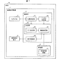
図1は、HMD10の要図構成である。HMD10に備えられている画像表示装置1は、センサパネル2、制御部3、記憶部4、画像表示素子5を含む。センサパネル2は、センサパネル2の検知面上にある空間に生じる静電容量値の変化を検知し、変化した静電容量値を示す情報を制御部3に送信する。
(Configuration of main part of image display device 1)
FIG. 1 is a schematic diagram of the
制御部3は、画像表示装置1における各種処理を実行する他、ジェスチャに対応する処理の実行等を行うものであり、位置特定部31、ジェスチャ判定部32、決定部33、および表示制御部36を備えている。
The
位置特定部31は、センサパネル2による検知データから、センサパネル2の検知面に対峙する(対向する)検知対象の位置(x座標、y座標、z座標)を特定するものである。なお、センサパネル2の検知面上に設定した2次元座標をx、y座標とし、センサパネル2の検知面に直交する方向をz軸方向としている。
The
位置特定部31は、特定したz座標(以下、距離z)に応じて、センサパネル2の検知分解能を切り替える。例えば、位置特定部31が特定した検知対象の位置(距離z)が、図3の(a)に示す基準値aと基準値bとの間にある場合、位置特定部31は、センサパネル2の電極構成を図3の(c)に示すパターン<1>とし、センサパネル2の検知可能な空間は検知空間Iであることを示す検知空間情報を決定部33に送信する。
The
また、実施形態1における位置特定部31は、特定した検知対象のx座標およびy座標を示す位置情報をジェスチャ判定部32に送信する。なお、位置特定部31の位置特定処理については図6にて後述する。
In addition, the
ジェスチャ判定部32は、位置特定部31から受信した位置情報から、検知対象の軌跡(入力操作)を特定し、特定した軌跡が所定のジェスチャであるか否かを判定する。所定のジェスチャは、記憶部4に格納されている処理内容情報41にて定義されているジェスチャであり、例えば、「円を描く」、「水平方向に移動する」である。検知対象の軌跡が所定のジェスチャである場合、ジェスチャ判定部32は、判定したジェスチャを示すジェスチャ情報を決定部33に送信する。
The
決定部33は、アプリ決定部34および機能決定部35を備え、記憶部4に格納されている処理内容情報41を参照して画像表示装置1の処理内容を決定する。アプリ決定部34は、位置特定部31から検知空間情報を受信すると、処理内容情報41を参照して起動させるアプリケーションを決定し、決定したアプリケーションを示す情報を機能決定部35に送信する。
The
機能決定部35は、ジェスチャ判定部32からジェスチャ情報を受信すると処理内容情報41を参照し、アプリ決定部34から受信した情報が示すアプリケーションにおいてジェスチャ情報が示すジェスチャに対応付けられた機能(所定の機能)を実行することを決定する。そして、機能決定部35は、決定した機能を表示制御部36に実行させる。
When receiving the gesture information from the
表示制御部(処理実行部)36は、機能決定部35からの指示に従い、画像表示素子5に表示する画像を制御する。画像表示素子5は、LCDおよび光学系を有し、LCDによって形成された画像を光学系を介してユーザに提示するものである。光学系は、LCDから出射された光を偏光し、ユーザの目に導くことが可能に構成されるものである。光学系は、例えば、全反射による導光が可能な透明基板からなる導光板と、回折反射が可能な反射型体積ホログラム回折格子等とで構成される。なお、画像表示素子5は、上記構成に限定されるものではなく、LCD自体をユーザの目の前方に配置してもよいし、その他HMDとして使用可能なものであれば本発明に適用される。
The display control unit (processing execution unit) 36 controls an image to be displayed on the image display element 5 in accordance with an instruction from the
記憶部4は、情報を記憶するものであり、フラッシュメモリ、ROM(Read Only Memory)などの不揮発性の記憶装置と、RAM(Random Access Memory)などの揮発性の記憶装置とによって構成される。不揮発性の記憶装置に記憶される内容としては、各種プログラム、各種動作設定値、各種データなどが挙げられる。一方、揮発性の記憶装置に記憶される内容としては、作業用ファイル、テンポラリファイルなどが挙げられる。本実施の形態では、記憶部4は、処理内容情報41を含む。
The
(画像表示装置の処理内容)
画像表示装置1が参照する処理内容情報について説明する。図4の(a)〜(d)は画像表示装置1の制御部3が参照する処理内容情報41の一例を示す図であり、制御部3の処理内容(所定の機能)と、ジェスチャとが対応付けられたテーブルである。制御部3の処理とは、画像表示素子5により表示される画像に対する処理である。例えば、当該画像に対して編集を行う処理(画像の縮尺変更を含む)であってもよいし、表示されているフォルダの画像をダブルクリックするようなユーザ操作が実行されると当該フォルダが開くという処理であってもよい。
(Processing contents of image display device)
Processing content information referred to by the image display device 1 will be described. 4A to 4D are diagrams illustrating an example of the
実施形態1における画像表示装置1が参照するテーブルは、図4の(a)に示す処理内容情報であり、各検知空間に割り当てられたアプリケーションの機能と、機能を実行させるトリガとなるユーザのジェスチャとが対応付けられている。なお、実施形態1におけるHMD10には、1つの画像表示装置1が備えられている構成とする。
The table referred to by the image display device 1 according to the first embodiment is the processing content information shown in FIG. 4A, and includes application functions assigned to each detection space and user gestures that trigger the execution of the functions. Are associated with each other. The
例えば、検知空間Iにはアプリケーション「画面の拡大・縮小」および機能「画面の縮小」が割り当てられ、当該機能には「円を描く」というジェスチャが対応付けられている。このため、検知空間Iにおいて「円を描く」というジェスチャが検知されると、図2の(d)に示す画面53の大きさが縮小される。なお、検知空間Iにおいて「水平方向に移動する」というジェスチャをしても、「画面の縮小」という機能は実行されない。
For example, the application “screen enlargement / reduction” and the function “screen reduction” are assigned to the detection space I, and the gesture “draw a circle” is associated with the function. For this reason, when the gesture “draw a circle” is detected in the detection space I, the size of the
また、例えば、検知空間IIにはアプリケーション「画面の拡大・縮小」および機能「画面の拡大」が割り当てられ、当該機能には「水平方向に移動する」というジェスチャが対応付けられている。このため、検知空間IIにおいて「水平方向に移動する」というジェスチャが検知されると、図2の(d)に示す画面53の大きさが拡大される。なお、検知空間IIにおいて「円を描く」というジェスチャをしても、「画面の拡大」という機能は実行されない。なお、図4の(b)は本実施形態の変形例にて後述し、図4の(c)は実施形態2にて後述し、図4(d)は実施形態3にて後述する。
Further, for example, the application “screen enlargement / reduction” and the function “screen enlargement” are assigned to the detection space II, and the gesture “moving horizontally” is associated with the function. For this reason, when the gesture “moving in the horizontal direction” is detected in the detection space II, the size of the
(機能決定処理)
図5は、本発明の実施形態1に係る画像表示装置1における処理の一例を示すフローチャートである。図5に示すように、位置特定部31は、センサパネル2から検知データを取得して、検知対象(ユーザの指など)の位置(x座標、y座標、z座標)を特定する位置特定処理を行う(S1)。なお、位置特定処理の詳細については、図6にて後述する。
(Function decision processing)
FIG. 5 is a flowchart showing an example of processing in the image display apparatus 1 according to Embodiment 1 of the present invention. As illustrated in FIG. 5, the
位置特定部31は、S1にて特定した検知対象のx座標およびy座標を示す位置情報をジェスチャ判定部32に送信する。また、実施形態1における位置特定部31は、S1にて特定した検知対象のz座標に応じて設定されたセンサパネル2の検知可能な空間を示す検知空間情報をアプリ決定部34に送信する。
The
アプリ決定部34は、S1にて特定された検知対象の位置(z座標)に応じた検知空間情報を受信すると、検知空間情報がどの検知空間を示すか(検知空間IまたはIIを示すか否か)を判定する(S2)。検知空間情報が検知空間IまたはIIであることを示す場合(S2でYES)、アプリ決定部34は、処理内容情報41を参照して検知空間に割り当てられたアプリケーションを起動することを決定する(S3)。一方、S2にてNOの場合、S1の処理に戻る。
When receiving the detection space information corresponding to the position (z coordinate) of the detection target specified in S1, the
また、ジェスチャ判定部32は、S1にて特定された検知対象の位置(x座標およびy座標)を示す位置情報を受信すると、受信した位置情報から検知対象の軌跡を特定し、特定した軌跡が所定のジェスチャであるか否かを判定する(S4)。検知対象の軌跡が所定のジェスチャである場合(S4でYES)、ジェスチャ判定部32は、判定したジェスチャを示すジェスチャ情報を機能決定部35に送信する。
In addition, when the
そして、機能決定部35は、S4にて判定されたジェスチャを示すジェスチャ情報を受信すると、アプリ決定部34により決定されたアプリケーションにおいてジェスチャ情報が示すジェスチャに対応付けられた機能を実行することを決定し、決定した機能を表示制御部36に実行させる(S5)。一方、S4にてNOの場合、S1の処理に戻る。
And the
例えば、図4の(a)に示す処理内容情報では、S1にて特定された検知対象の位置(z座標)が検知空間Iである場合、検知空間Iに割り当てられたアプリケーション「画面の拡大・縮小」が決定され(S3)、さらに、S4にて判定されたジェスチャが「円を描く」である場合、機能「画面の縮小」が決定される。そして、表示制御部36は、機能決定部35からの通知に従い、図2の(d)に示す画面53の大きさを縮小する。
For example, in the processing content information shown in FIG. 4A, when the position (z coordinate) of the detection target specified in S1 is the detection space I, the application assigned to the detection space I “screen enlargement / When “reduction” is determined (S3) and the gesture determined in S4 is “draw a circle”, the function “reduction of screen” is determined. The
上記の構成によれば、ユーザは、表示されている画像54に対して、所定の機能を実行させるための入力操作を行うことができる。例えば、所定の機能をイメージするような入力操作を当該所定の機能と対応付けたジェスチャとすれば、ユーザは、直感に即した入力操作を行うことが可能となる。
According to said structure, the user can perform input operation for performing a predetermined | prescribed function with respect to the
(位置特定処理)
図6は、上記画像表示装置1における位置特定処理の一例を示すフローチャートである。まず、位置特定部31は、センサパネル2の電極間隔がパターン<1>の電極間隔に設定されているか否かを確認し(S101)、電極間隔がパターン<1>の電極間隔に設定されている場合(S101でYES)、S102に進む。一方、電極間隔がパターン<1>の電極間隔に設定されていない場合(S101でNO)、S107に進む。S107では、位置特定部31が、電極間隔をパターン<1>の電極間隔に設定して(切り替えて)S102に進む。なお、S107における電極間隔の設定は、暫定的な設定である。暫定的な設定とは、センサパネル2において検知電極として寄与する電極間隔が不定になることを防ぐための一時的な設定である。
(Positioning process)
FIG. 6 is a flowchart showing an example of the position specifying process in the image display apparatus 1. First, the
次に、位置特定部31は、検出レベル(検知対象のz座標)が基準値aを超えたか否かを判定し(S102)、検出レベルが基準値aを超えた場合(S102でYES)、S103に進む。一方、検出レベルが基準値aを超えていない場合(S102でNO)、S102の動作を最初からやり直す。そして、位置特定部31は、検出レベルが基準値bを超えたか否かを判定し(S103)、検出レベルが基準値bを超えた場合(S103でYES)、S104に進む。一方、検出レベルが基準値bを超えていない場合(S103でNO)、S108に進む。
Next, the
S108では、位置特定部31は、センサパネル2の電極間隔を最適な電極間隔としてパターン<1>に設定する。S108の後、位置特定部31は、センサパネル2による検知データから、検知対象の位置(x座標、y座標およびz座標)を特定し(S109)、S101に戻る。
In S108, the
なお、実施形態1における位置特定処理において、位置特定部31は、S109にて特定した検知対象のx座標およびy座標を示す位置情報をジェスチャ判定部32に送信するとともに、S108にて設定したセンサパネル2の検知可能な空間(検知空間I)を示す検知空間情報をアプリ決定部34に送信する。
In the position specifying process in the first embodiment, the
次に、位置特定部31は、パターン<2>の電極間隔に設定されているか否かを確認し(S104)、電極間隔がパターン<2>の電極間隔に設定されている場合(S104でYES)、S105に進む。一方、電極間隔がパターン<2>の電極間隔に設定されていない場合(S104でNO)、S110に進む。ステップS110では、位置特定部31は、電極間隔をパターン<2>の電極間隔に設定して(切り替えて)S105に進む。なお、S110における電極間隔の設定は、暫定的な設定である。
Next, the
S105では、位置特定部31は、センサパネル2の電極間隔を最適な電極間隔としてパターン<2>に設定する。S105の後、位置特定部31は、センサパネル2による検知データから、検知対象の位置(x座標、y座標およびz座標)を特定し(S106)、S103に戻る。
In S105, the
なお、実施形態1における位置特定処理において、位置特定部31は、S106にて特定した検知対象のx座標およびy座標を示す位置情報をジェスチャ判定部32に送信するとともに、S105にて設定したセンサパネル2の検知可能な空間(検知空間II)を示す検知空間情報をアプリ決定部34に送信する。なお、上述した位置特定処理は、任意の時間ごとに行われるものとする。
In the position specifying process in the first embodiment, the
(変形例)
上記では1つの画像表示装置1が備えられているHMD10について説明したが、HMD10は、右目用および左目用として2つの画像表示装置1を備える構成であってもよい。この構成の場合、センサパネル2が検知する検知空間IおよびIIを、右目側と左目側とにそれぞれ分割して、分割した検知空間に異なるアプリケーションを割り当ててもよい。ここで、右目用のセンサパネル2が検知する空間を操作エリアAとし、左目用のセンサパネル2が検知する空間を操作エリアBとする。
(Modification)
Although the
実施形態1の変形例における画像表示装置1が参照するテーブルは、図4の(b)に示す処理内容情報であり、例えば、操作エリアAおよび操作エリアBに、異なるアプリケーションがそれぞれ割り当てられている。より具体的には、操作エリアAにおける検知空間Iにて「円を描く」というジェスチャが検知されると、図2の(d)に示す画面53の大きさが縮小され、操作エリアAにおける検知空間IIにて「水平方向に移動する」というジェスチャが検知されると、図2の(d)に示す画面53の大きさが拡大される。また、操作エリアBにおける検知空間Iにて「円を描く」というジェスチャが検知されると、図2の(d)に示す画像54が1つ前に表示していた画像54に戻り、操作エリアBにおける検知空間IIにて「水平方向に移動する」というジェスチャが検知されると、図2の(d)に示す画像54が次に表示される画像54に進む。
The table referred to by the image display device 1 in the modification of the first embodiment is the processing content information shown in FIG. 4B. For example, different applications are assigned to the operation area A and the operation area B, respectively. . More specifically, when the gesture “draw a circle” is detected in the detection space I in the operation area A, the size of the
上記の構成によれば、ユーザは、右目用および左目用のそれぞれのセンサパネル2に対して入力操作を行い、異なる所定の機能を実行させることができる。なお、画像表示素子5は、右目用のセンサパネル2および左目用のセンサパネル2のうち少なくとも一方に備えられていればよく、図2の(d)に示す画像54は、任意の画像表示素子5に表示される構成である。
According to said structure, the user can perform input operation with respect to each
〔実施形態2〕
本発明の他の実施形態について、図4の(c)および図7の(a)に基づいて説明すれば、以下のとおりである。なお、説明の便宜上、前記実施形態にて説明した部材と同じ機能を有する部材については、同じ符号を付記し、その説明を省略する。実施形態2におけるHMD10は、右目用および左目用として2つの画像表示装置1を備える構成である。実施形態2における画像表示装置1は、右目用のセンサパネル2が検知する空間である操作エリアA、および左目用のセンサパネル2が検知する空間である操作エリアBにて、検知対象(ユーザの別の指)をそれぞれ検知する点で、実施形態1における画像表示装置1と異なる。
[Embodiment 2]
The following will describe another embodiment of the present invention with reference to FIG. 4C and FIG. 7A. For convenience of explanation, members having the same functions as those described in the embodiment are given the same reference numerals, and descriptions thereof are omitted. The
実施形態2における画像表示装置1が参照するテーブルは、図4の(c)に示す処理内容情報であり、各検知空間にアプリケーション・機能・ジェスチャが対応付けられている。例えば、検知空間Iにおいて、操作エリアAにはアプリケーションが割り当てられ、操作エリアBでは機能とジェスチャとが対応付けられている。 The table referred to by the image display device 1 in the second embodiment is the processing content information shown in FIG. 4C, and an application, a function, and a gesture are associated with each detection space. For example, in the detection space I, an application is assigned to the operation area A, and a function and a gesture are associated with each other in the operation area B.
より具体的には、ユーザが、右手の指を検知空間Iにおける操作エリアAにて立てると、アプリ決定部34は、検知空間Iにおける操作エリアAに割り当てられたアプリケーション「画面の拡大・縮小」を決定する。そしてさらに、ユーザが、左手の指で検知空間Iにおける操作エリアBにて所定のジェスチャ「円を描く」を行うと、機能決定部35は、当該ジェスチャに対応付けられた機能「縮小」を決定し、表示制御部36は、図2の(d)に示す画面53の大きさを縮小する。なお、本実施形態では、操作エリアAにて検知される検知対象と、操作エリアBにて検知される検知対象とが、同一の検知空間にある場合に、表示制御部36が実行する機能が決定される。
More specifically, when the user stands up with the finger of the right hand in the operation area A in the detection space I, the
(機能決定処理の別の例)
図7の(a)は、本発明の実施形態2に係る画像表示装置1における処理の一例を示すフローチャートである。図7の(a)に示すように、位置特定部31は、右目用のセンサパネル2から検知データを取得して、操作エリアAにおける検知対象(ユーザの指など)の位置(x座標、y座標、z座標)を特定する位置特定処理を行う(S21)。そして、位置特定部31は、S21にて特定した検知対象のz座標に応じて設定されたセンサパネル2の検知可能な空間を示す検知空間情報をアプリ決定部34に送信する。なお、S21の具体的な処理は、図6の位置特定処理と同様であるが、検知対象のz座標のみを特定する処理であってもよい。
(Another example of function decision processing)
(A) of FIG. 7 is a flowchart which shows an example of the process in the image display apparatus 1 which concerns on
次に、アプリ決定部34は、S21にて特定された検知対象の位置(z座標)に応じた検知空間情報を受信すると、図4の(c)に示す処理内容情報41を参照して検知空間に割り当てられたアプリケーションを起動することを決定する(S22)。
Next, when receiving the detection space information corresponding to the position (z coordinate) of the detection target specified in S21, the
また、位置特定部31は、左目用のセンサパネル2から検知データを取得して、操作エリアBにおける検知対象(ユーザの指など)の位置(x座標、y座標、z座標)を特定する位置特定処理を行う(S23)。そして、位置特定部31は、S23にて特定した検知対象のx座標およびy座標を示す位置情報をジェスチャ判定部32に送信する。なお、S23の具体的な処理は、図6の位置特定処理と同様であるが、検知対象のx座標およびy座標を特定する処理であってもよい。
The
そして、ジェスチャ判定部32は、S23にて特定された検知対象の位置を示す位置情報を受信すると、受信した位置情報から検知対象の軌跡を特定し、特定した軌跡が所定のジェスチャであるか否かを図4の(c)に示す処理内容情報41を参照して判定する(S24)。検知対象の軌跡が所定のジェスチャである場合(S24でYES)、ジェスチャ判定部32は、判定したジェスチャを示すジェスチャ情報を機能決定部35に送信する。
And the
そして、機能決定部35は、S24にて判定されたジェスチャを示すジェスチャ情報を受信すると、アプリ決定部34により決定されたアプリケーションにおいてジェスチャ情報が示すジェスチャに対応付けられた機能を実行することを決定し、決定した機能を表示制御部36に実行させる(S25)。一方、S24でNOの場合、S21の処理に戻る。
And the
上記の構成によれば、右目用のセンサパネル2にて検出したユーザの指の位置(z座標)から起動するアプリケーションを決定し、左目用のセンサパネル2にて検出したユーザの指の動き(ジェスチャ)から実行する機能を決定することが可能となる。それゆえ、実行する機能のバリエーションを増やしつつ、ユーザの直感に即した入力操作を行うことが可能となる。
According to the above configuration, an application to be activated is determined from the position (z coordinate) of the user's finger detected by the right-
〔実施形態3〕
本発明の他の実施形態について、図4の(d)および図7の(b)に基づいて説明すれば、以下のとおりである。実施形態3におけるHMD10は、1つの画像表示装置1を備える構成である。実施形態3では、所定のジェスチャが検知されることによってアプリケーションが決定され、決定されたアプリケーションに対応付けられた所定の機能を実行するためのパラメータを、検知される検知対象とセンサパネル2の検知面との距離zに連動させて変更する点で、実施形態1と異なる。
[Embodiment 3]
The following will describe another embodiment of the present invention with reference to FIG. 4D and FIG. 7B. The
実施形態3における画像表示装置1が参照するテーブルは、図4の(d)に示す処理内容情報である。当該処理内容情報では、所定のジェスチャごとにアプリケーションが割り当てられており、検知空間ごとに所定の機能が調整項目として対応付けられている。 The table referred to by the image display device 1 in the third embodiment is the processing content information shown in (d) of FIG. In the processing content information, an application is assigned for each predetermined gesture, and a predetermined function is associated as an adjustment item for each detection space.
例えば、ユーザが、検知空間IまたはIIにおいて指で「円を描く」ジェスチャを行うとアプリケーション「画面の拡大・縮小」が決定される。そして、検知された指の位置が「検知空間I」にある場合、調整項目「画面の縮小」が決定され、図2の(d)に示す画面53の大きさが、センサパネル2の検出面と検出対象である指との距離zの変化に追従して縮小されていく。また、検知された指の位置が「検知空間II」にある場合、調整項目「画面の拡大」が決定され、図2の(d)に示す画面53の大きさが、センサパネル2の検出面と検出対象である指との距離zの変化に追従して拡大されていく。
For example, when the user performs a “draw circle” gesture with the finger in the detection space I or II, the application “enlargement / reduction of screen” is determined. When the detected finger position is in “detection space I”, the adjustment item “screen reduction” is determined, and the size of the
(機能決定処理の別の例)
図7の(b)は、本発明の実施形態3に係る画像表示装置1における処理の一例を示すフローチャートである。図7の(b)に示すように、位置特定部31は、センサパネル2から検知データを取得して、検知対象(ユーザの指など)の位置(x座標、y座標、z座標)を特定する位置特定処理を行う(S1)。なお、実施形態3における位置特定部31は、S1にて特定した検知対象のz座標に応じて設定されたセンサパネル2の検知可能な空間を示す検知空間情報を機能決定部35に送信する。
(Another example of function decision processing)
FIG. 7B is a flowchart illustrating an example of processing in the image display apparatus 1 according to the third embodiment of the present invention. As shown in FIG. 7B, the
そして、ジェスチャ判定部32は、S1にて特定された検知対象の位置(x座標およびy座標)を示す位置情報を受信すると、受信した位置情報から検知対象の軌跡を特定し、特定した軌跡が所定のジェスチャであるか否かを、図4の(d)に示す処理内容情報41を参照して判定する(S31)。
And the
検知対象の軌跡が所定のジェスチャである場合(S31でYES)、ジェスチャ判定部32は、判定したジェスチャを示すジェスチャ情報をアプリ決定部34に送信する。アプリ決定部34は、S31にて判定されたジェスチャを示すジェスチャ情報を受信すると、図4の(d)に示す処理内容情報を参照して検知空間に割り当てられたアプリケーションを起動することを決定する(S32)。一方、S31でNOの場合、S1の処理に戻る。
When the detection target trajectory is a predetermined gesture (YES in S31), the
また、機能決定部35は、S1にて特定された検知対象の位置(z座標)に応じた検知空間情報を受信すると、検知空間情報が検知空間IまたはIIを示すか否かを判定する(S33)。検知空間情報が検知空間IまたはIIであることを示す場合(S33でYES)、機能決定部35は、図4の(d)に示す処理内容情報を参照して検知空間に割り当てられた調整項目を実行することを決定し、決定した調整項目を、検知対象の位置(z座標)に連動させて表示制御部36に実行させる(S34)。一方、S33でNOの場合、S1の処理に戻る。上記の構成によれば、ユーザは、直感に即した入力操作を行うことが可能となる。
Further, when receiving the detection space information corresponding to the position (z coordinate) of the detection target specified in S1, the
〔ソフトウェアによる実現例〕
画像表示装置1の制御ブロック(特に位置特定部31、ジェスチャ判定部32、アプリ決定部34、機能決定部35および表示制御部36)は、集積回路(ICチップ)等に形成された論理回路(ハードウェア)によって実現してもよいし、CPU(Central Processing Unit)を用いてソフトウェアによって実現してもよい。
[Example of software implementation]
The control block (particularly the
後者の場合、画像表示装置1は、各機能を実現するソフトウェアであるプログラムの命令を実行するCPU、上記プログラムおよび各種データがコンピュータ(またはCPU)で読み取り可能に記録されたROM(Read Only Memory)または記憶装置(これらを「記録媒体」と称する)、上記プログラムを展開するRAM(Random Access Memory)などを備えている。そして、コンピュータ(またはCPU)が上記プログラムを上記記録媒体から読み取って実行することにより、本発明の目的が達成される。上記記録媒体としては、「一時的でない有形の媒体」、例えば、テープ、ディスク、カード、半導体メモリ、プログラマブルな論理回路などを用いることができる。また、上記プログラムは、該プログラムを伝送可能な任意の伝送媒体(通信ネットワークや放送波等)を介して上記コンピュータに供給されてもよい。なお、本発明は、上記プログラムが電子的な伝送によって具現化された、搬送波に埋め込まれたデータ信号の形態でも実現され得る。 In the latter case, the image display device 1 includes a CPU that executes instructions of a program that is software that implements each function, and a ROM (Read Only Memory) in which the program and various data are recorded so as to be readable by a computer (or CPU). Alternatively, a storage device (these are referred to as “recording media”), a RAM (Random Access Memory) that expands the program, and the like are provided. And the objective of this invention is achieved when a computer (or CPU) reads the said program from the said recording medium and runs it. As the recording medium, a “non-temporary tangible medium” such as a tape, a disk, a card, a semiconductor memory, a programmable logic circuit, or the like can be used. The program may be supplied to the computer via an arbitrary transmission medium (such as a communication network or a broadcast wave) that can transmit the program. The present invention can also be realized in the form of a data signal embedded in a carrier wave in which the program is embodied by electronic transmission.
なお、上記各実施形態における説明では、各検知空間に応じてジェスチャとアプリケーションの機能との対応付けが異なる様に設定しているが、本発明はこれに限定されるものではなく、各検知空間においてジェスチャとアプリケーションの機能とが同じ対応付けであってもよい。 In the description of each of the above embodiments, the correspondence between the gesture and the function of the application is set to be different depending on each detection space. However, the present invention is not limited to this, and each detection space is not limited to this. The gesture and the application function may be associated with each other.
〔まとめ〕
本発明の態様1に係る画像表示装置(1)は、片面が表示面である画像表示素子(5)と、上記画像表示素子の上記表示面とは反対側の面に重畳されたセンサパネル(2)とを備え、上記センサパネルは上記画像表示素子の上記表示面側とは反対側の空間(検知空間Iおよび検知空間II)におけるユーザによる指示体の動きを検知する。
[Summary]
An image display device (1) according to an aspect 1 of the present invention includes an image display element (5) whose one side is a display surface, and a sensor panel superimposed on a surface opposite to the display surface of the image display element ( 2), and the sensor panel detects the movement of the indicator by the user in the space (detection space I and detection space II) opposite to the display surface side of the image display element.
上記の構成によれば、画像表示装置は、画像表示素子と、画像表示素子に重畳されたセンサパネルとを備え、センサパネルは、画像表示素子の表示面側とは反対側の空間におけるユーザによる指示体の動きを検知する。このため、画像表示装置は、ユーザに画像を提示するとともに、画像表示素子の表示面とは反対側の空間においてユーザの入力操作を検知することが可能となる。それゆえ、ユーザは、別途、入力デバイスを用いることなく、画像表示装置に対する操作を行うことが可能となる。 According to said structure, an image display apparatus is provided with an image display element and the sensor panel superimposed on the image display element, and a sensor panel by the user in the space on the opposite side to the display surface side of an image display element The movement of the indicator is detected. Therefore, the image display apparatus can present an image to the user and detect the user's input operation in a space on the opposite side to the display surface of the image display element. Therefore, the user can perform an operation on the image display apparatus without using an input device separately.
例えば、画像表示装置をヘッドマウントディスプレイに適用した場合、ユーザは、画像表示素子に表示された画像を視認しつつ、画像表示素子の表示面とは反対側の空間においてユーザ操作を検知することができる。このため、外部装置の入力デバイス等を用いる場合と比較して、よりユーザフレンドリーな操作感を提供することができる。 For example, when the image display device is applied to a head-mounted display, the user can detect a user operation in a space opposite to the display surface of the image display element while visually recognizing the image displayed on the image display element. it can. For this reason, compared with the case where the input device of an external device etc. are used, a user-friendly operation feeling can be provided.
本発明の態様2に係る画像表示装置は、上記態様1において、上記センサパネルにて検知される上記指示体の動きが所定のジェスチャであるか否かを判定するジェスチャ判定部(32)と、上記指示体の動きが上記所定のジェスチャであると判定された場合、上記所定のジェスチャに対応付けられた所定の機能を実行する処理実行部(表示制御部36)と、を備えていてもよい。
An image display device according to
上記の構成によれば、画像表示装置は、ユーザの入力操作が所定のジェスチャである場合に、所定のジェスチャに対応付けられた機能を実行する。このため、ユーザは、所定のジェスチャによる入力操作を行うことにより、表示される画像に対し所定の機能を実行させることができる。それゆえ、例えば、所定の機能をイメージするようなジェスチャを当該所定の機能と対応付けたジェスチャとすれば、ユーザは、直感に即した入力操作を行うことが可能となる。 According to the above configuration, the image display device executes a function associated with a predetermined gesture when the user's input operation is a predetermined gesture. Therefore, the user can execute a predetermined function on the displayed image by performing an input operation using a predetermined gesture. Therefore, for example, if a gesture that imagines a predetermined function is used as a gesture associated with the predetermined function, the user can perform an input operation in an intuitive manner.
本発明の態様3に係る画像表示装置は、上記態様2において、上記所定の機能は、上記画像表示素子により表示される画像に対する処理を実行する機能であってもよい。上記の構成によれば、ユーザは、画像表示素子に表示される画像を処理するための入力操作を行うことが可能となる。
In the image display device according to
本発明の態様4に係る画像表示装置は、上記態様2または3において、上記処理実行部は、一つの上記ジェスチャについて、上記センサパネルの検知面と上記指示体(指h)との距離(z)に応じて異なる上記所定の機能を実行してもよい。上記の構成によれば、画像表示装置は、センサパネルの検知面と入力操作を行う指示体との距離に応じて異なる機能を実行する。このため、センサパネルの検知面と入力操作を行う指示体との距離に応じて、実行する機能のバリエーションを増やすことができる。
The image display device according to
本発明の態様5に係る画像表示装置は、上記態様2から4の何れか一態様において、上記センサパネルを複数備え、上記所定の機能は、上記センサパネルごとに、上記所定のジェスチャに対応付けられてもよい。上記の構成によれば、センサパネルごとに、所定の機能が所定のジェスチャに対応付けられていることとなる。それゆえ、ユーザは、それぞれのセンサパネルに対して入力操作を行い、異なる機能を実行させることができる。
An image display device according to an aspect 5 of the present invention includes the sensor panel according to any one of the
本発明の態様6に係る画像表示装置は、上記態様2から5の何れか一態様において、上記ジェスチャ判定部にて判定された上記ジェスチャに対応付けられた上記所定の機能を実行するためのパラメータを、上記指示体と上記センサパネルの検知面との距離に連動させて変更してもよい。
The image display device according to aspect 6 of the present invention is the parameter for executing the predetermined function associated with the gesture determined by the gesture determination unit according to any one of the
上記の構成によれば、画像表示装置は、ユーザによる指示体の動きが所定のジェスチャであるか否かを判定し、所定のジェスチャであると判定されたジェスチャに対応付けられた機能を指示体とパネルの検知面との距離に連動して実行する。例えば、パネルの検知面からの距離が10cm未満となる空間において、ユーザの指がパネルの検知面に近づく場合、画像の表示領域が拡大される。また、パネルの検知面からの距離が10cm以上15cm以下となる空間において、ユーザの指がセンサパネルの検知面から遠ざかる場合、画像の表示領域が縮小される。このため、ユーザは、表示されている画像に対して、自身の入力操作の動きに合わせた調節を行うことが可能となる。それゆえ、ユーザは、直感に即した入力操作を行うことが可能となる。 According to the above configuration, the image display device determines whether or not the movement of the indicator by the user is a predetermined gesture, and indicates the function associated with the gesture determined to be the predetermined gesture. Executes in conjunction with the distance between the panel and the sensing surface of the panel. For example, in a space where the distance from the detection surface of the panel is less than 10 cm, when the user's finger approaches the detection surface of the panel, the image display area is enlarged. In addition, in a space where the distance from the detection surface of the panel is 10 cm or more and 15 cm or less, when the user's finger moves away from the detection surface of the sensor panel, the image display area is reduced. For this reason, the user can adjust the displayed image in accordance with the movement of his input operation. Therefore, the user can perform an input operation in line with intuition.
本発明の態様7に係るヘッドマウントディスプレイは、上記態様1から6の何れか一態様における画像表示装置を、装着時にユーザの目の前方となる位置に備えていてもよい。上記の構成によれば、上記態様1から6の何れか1態様と同様の効果を奏する。 A head mounted display according to aspect 7 of the present invention may include the image display device according to any one of aspects 1 to 6 at a position that is in front of the user's eyes when worn. According to said structure, there exists an effect similar to any one aspect of the said aspects 1-6.
本発明の各態様に係る画像表示装置は、コンピュータによって実現してもよく、この場合には、コンピュータを上記画像表示装置が備える各部(ソフトウェア要素)として動作させることにより上記画像表示装置をコンピュータにて実現させる画像表示装置の制御プログラム、およびそれを記録したコンピュータ読み取り可能な記録媒体も、本発明の範疇に入る。 The image display apparatus according to each aspect of the present invention may be realized by a computer. In this case, the image display apparatus is operated on each computer by causing the computer to operate as each unit (software element) included in the image display apparatus. The control program for the image display apparatus realized and the computer-readable recording medium on which the control program is recorded also fall within the scope of the present invention.
本発明は上述した各実施形態に限定されるものではなく、請求項に示した範囲で種々の変更が可能であり、異なる実施形態にそれぞれ開示された技術的手段を適宜組み合わせて得られる実施形態についても本発明の技術的範囲に含まれる。さらに、各実施形態にそれぞれ開示された技術的手段を組み合わせることにより、新しい技術的特徴を形成することができる。 The present invention is not limited to the above-described embodiments, and various modifications are possible within the scope shown in the claims, and embodiments obtained by appropriately combining technical means disclosed in different embodiments. Is also included in the technical scope of the present invention. Furthermore, a new technical feature can be formed by combining the technical means disclosed in each embodiment.
本発明は、ユーザの頭部に装着されるヘッドマウントディスプレイに利用することができる。 The present invention can be used for a head mounted display mounted on a user's head.
1 画像表示装置、10 HMD(ヘッドマウントディスプレイ)
2 センサパネル、3 制御部、4 記憶部、5 画像表示素子
31 位置特定部、32 ジェスチャ判定部、33 決定部、34 アプリ決定部
35 機能決定部、36 表示制御部(処理実行部)、 41 処理内容情報
I・II 検知空間(空間)、z 距離、h 指(検知対象)
1 Image display device, 10 HMD (head mounted display)
2 sensor panel, 3 control unit, 4 storage unit, 5
Claims (5)
上記画像表示素子の上記表示面とは反対側の面に重畳されたセンサパネルとを備え、
上記画像表示素子と上記センサパネルとは光を透過する透過型の素子であり、
上記センサパネルは、上記画像表示素子の上記表示面側とは反対側の空間におけるユーザによる指示体の動きを検知することを特徴とする画像表示装置。 An image display element whose one side is a display surface;
A sensor panel superimposed on a surface opposite to the display surface of the image display element,
The image display element and the sensor panel are transmissive elements that transmit light,
The image display apparatus, wherein the sensor panel detects a movement of an indicator by a user in a space opposite to the display surface side of the image display element.
上記指示体の動きが上記所定のジェスチャであると判定された場合、上記所定のジェスチャに対応付けられた所定の機能を実行する処理実行部と、を備えることを特徴とする請求項1に記載の画像表示装置。 A gesture determination unit that determines whether or not the movement of the indicator detected by the sensor panel is a predetermined gesture;
The process execution part which performs the predetermined | prescribed function matched with the said predetermined | prescribed gesture when it determines with the motion of the said indicator being the said predetermined | prescribed gesture is provided. Image display device.
上記画像表示素子の上記表示面とは反対側の面に重畳されたセンサパネルとを複数備え、
上記複数のセンサパネルのそれぞれは、上記画像表示素子の上記表示面側とは反対側の空間におけるユーザによる指示体の動きを検知する、画像表示装置であって、
上記画像表示装置は、さらに、上記複数のセンサパネルのそれぞれにて検知される上記指示体の動きが所定のジェスチャであるか否かを判定するジェスチャ判定部と、
上記指示体の動きが上記所定のジェスチャであると判定された場合、上記所定のジェスチャに対応付けられた所定の機能を実行する処理実行部と、を備え、
上記所定の機能は、上記センサパネルごとに、上記所定のジェスチャに対応付けられていることを特徴とする画像表示装置。 An image display element whose one side is a display surface;
A plurality of sensor panels superimposed on a surface opposite to the display surface of the image display element;
Each of the plurality of sensor panels is an image display device that detects a movement of an indicator by a user in a space opposite to the display surface side of the image display element,
The image display device further includes a gesture determination unit that determines whether or not the movement of the indicator detected by each of the plurality of sensor panels is a predetermined gesture;
A process execution unit that executes a predetermined function associated with the predetermined gesture when the movement of the indicator is determined to be the predetermined gesture;
The predetermined function is, for each of the sensor panel, it images the display device you wherein associated with the above predetermined gesture.
Priority Applications (1)
| Application Number | Priority Date | Filing Date | Title |
|---|---|---|---|
| JP2015103917A JP6567324B2 (en) | 2015-05-21 | 2015-05-21 | Image display device and head mounted display |
Applications Claiming Priority (1)
| Application Number | Priority Date | Filing Date | Title |
|---|---|---|---|
| JP2015103917A JP6567324B2 (en) | 2015-05-21 | 2015-05-21 | Image display device and head mounted display |
Publications (2)
| Publication Number | Publication Date |
|---|---|
| JP2016218803A JP2016218803A (en) | 2016-12-22 |
| JP6567324B2 true JP6567324B2 (en) | 2019-08-28 |
Family
ID=57578979
Family Applications (1)
| Application Number | Title | Priority Date | Filing Date |
|---|---|---|---|
| JP2015103917A Active JP6567324B2 (en) | 2015-05-21 | 2015-05-21 | Image display device and head mounted display |
Country Status (1)
| Country | Link |
|---|---|
| JP (1) | JP6567324B2 (en) |
Family Cites Families (6)
| Publication number | Priority date | Publication date | Assignee | Title |
|---|---|---|---|---|
| JP3852368B2 (en) * | 2002-05-16 | 2006-11-29 | ソニー株式会社 | Input method and data processing apparatus |
| JP4816713B2 (en) * | 2008-11-25 | 2011-11-16 | ソニー株式会社 | Information processing apparatus, information processing method, and information processing program |
| US9030407B2 (en) * | 2011-12-21 | 2015-05-12 | Nokia Technologies Oy | User gesture recognition |
| KR102164453B1 (en) * | 2012-04-07 | 2020-10-13 | 삼성전자주식회사 | Object control method performed in device including transparent display, the device, and computer readable recording medium thereof |
| JP5953963B2 (en) * | 2012-06-13 | 2016-07-20 | ソニー株式会社 | Head-mounted image display device |
| JP6340301B2 (en) * | 2014-10-22 | 2018-06-06 | 株式会社ソニー・インタラクティブエンタテインメント | Head mounted display, portable information terminal, image processing apparatus, display control program, display control method, and display system |
-
2015
- 2015-05-21 JP JP2015103917A patent/JP6567324B2/en active Active
Also Published As
| Publication number | Publication date |
|---|---|
| JP2016218803A (en) | 2016-12-22 |
Similar Documents
| Publication | Publication Date | Title |
|---|---|---|
| JP5957875B2 (en) | Head mounted display | |
| EP2732357B1 (en) | Methods and systems for a virtual input device | |
| US8791962B2 (en) | Information processing device, information processing method, and program for 3D object selection and interaction | |
| US9274608B2 (en) | Systems and methods for triggering actions based on touch-free gesture detection | |
| US10282067B2 (en) | Method and apparatus of controlling an interface based on touch operations | |
| EP2638461B1 (en) | Apparatus and method for user input for controlling displayed information | |
| JP6064988B2 (en) | Head mounted display | |
| JP2008009759A (en) | Touch panel device | |
| CN109643206B (en) | Control device, display device, program, and detection method | |
| JP2013125247A (en) | Head-mounted display and information display apparatus | |
| CN108027656B (en) | Input device, input method, and program | |
| KR20160080109A (en) | Systems and techniques for user interface control | |
| EP2489195A1 (en) | Autostereoscopic rendering and display apparatus | |
| US20130106842A1 (en) | Information processing apparatus, information processing method, and program | |
| JP2012108723A (en) | Instruction reception device | |
| US10334233B2 (en) | Portable device that controls photography mode, and control method therefor | |
| EP3088991B1 (en) | Wearable device and method for enabling user interaction | |
| JP6567324B2 (en) | Image display device and head mounted display | |
| JP6630164B2 (en) | Electronic device, control method therefor, program, and storage medium | |
| WO2014061310A1 (en) | Display object control system, display object control method, and program | |
| US9563344B2 (en) | Information processing method and electronic apparatus | |
| CN109769395A (en) | Capacitive touch screen mirror equipment and manufacturing method | |
| JP2011180690A (en) | Display control apparatus, display control method, and display control program | |
| CN115735182A (en) | System and method for dynamic shape shorthand | |
| US20140215363A1 (en) | Input display device |
Legal Events
| Date | Code | Title | Description |
|---|---|---|---|
| A621 | Written request for application examination |
Free format text: JAPANESE INTERMEDIATE CODE: A621 Effective date: 20180323 |
|
| A977 | Report on retrieval |
Free format text: JAPANESE INTERMEDIATE CODE: A971007 Effective date: 20181203 |
|
| A131 | Notification of reasons for refusal |
Free format text: JAPANESE INTERMEDIATE CODE: A131 Effective date: 20181225 |
|
| A521 | Request for written amendment filed |
Free format text: JAPANESE INTERMEDIATE CODE: A523 Effective date: 20190220 |
|
| TRDD | Decision of grant or rejection written | ||
| A01 | Written decision to grant a patent or to grant a registration (utility model) |
Free format text: JAPANESE INTERMEDIATE CODE: A01 Effective date: 20190702 |
|
| A61 | First payment of annual fees (during grant procedure) |
Free format text: JAPANESE INTERMEDIATE CODE: A61 Effective date: 20190731 |
|
| R150 | Certificate of patent or registration of utility model |
Ref document number: 6567324 Country of ref document: JP Free format text: JAPANESE INTERMEDIATE CODE: R150 |