WO2016063754A1 - 内燃機関のピストン製造方法および内燃機関用ピストンの摩擦封孔装置 - Google Patents
内燃機関のピストン製造方法および内燃機関用ピストンの摩擦封孔装置 Download PDFInfo
- Publication number
- WO2016063754A1 WO2016063754A1 PCT/JP2015/078863 JP2015078863W WO2016063754A1 WO 2016063754 A1 WO2016063754 A1 WO 2016063754A1 JP 2015078863 W JP2015078863 W JP 2015078863W WO 2016063754 A1 WO2016063754 A1 WO 2016063754A1
- Authority
- WO
- WIPO (PCT)
- Prior art keywords
- piston
- thermal conductivity
- low thermal
- combustion engine
- internal combustion
- Prior art date
- Legal status (The legal status is an assumption and is not a legal conclusion. Google has not performed a legal analysis and makes no representation as to the accuracy of the status listed.)
- Ceased
Links
Images




Classifications
-
- F—MECHANICAL ENGINEERING; LIGHTING; HEATING; WEAPONS; BLASTING
- F02—COMBUSTION ENGINES; HOT-GAS OR COMBUSTION-PRODUCT ENGINE PLANTS
- F02F—CYLINDERS, PISTONS OR CASINGS, FOR COMBUSTION ENGINES; ARRANGEMENTS OF SEALINGS IN COMBUSTION ENGINES
- F02F3/00—Pistons
- F02F3/10—Pistons having surface coverings
- F02F3/12—Pistons having surface coverings on piston heads
-
- B—PERFORMING OPERATIONS; TRANSPORTING
- B23—MACHINE TOOLS; METAL-WORKING NOT OTHERWISE PROVIDED FOR
- B23K—SOLDERING OR UNSOLDERING; WELDING; CLADDING OR PLATING BY SOLDERING OR WELDING; CUTTING BY APPLYING HEAT LOCALLY, e.g. FLAME CUTTING; WORKING BY LASER BEAM
- B23K20/00—Non-electric welding by applying impact or other pressure, with or without the application of heat, e.g. cladding or plating
- B23K20/12—Non-electric welding by applying impact or other pressure, with or without the application of heat, e.g. cladding or plating the heat being generated by friction; Friction welding
- B23K20/122—Non-electric welding by applying impact or other pressure, with or without the application of heat, e.g. cladding or plating the heat being generated by friction; Friction welding using a non-consumable tool, e.g. friction stir welding
- B23K20/128—Non-electric welding by applying impact or other pressure, with or without the application of heat, e.g. cladding or plating the heat being generated by friction; Friction welding using a non-consumable tool, e.g. friction stir welding making use of additional material
-
- B—PERFORMING OPERATIONS; TRANSPORTING
- B23—MACHINE TOOLS; METAL-WORKING NOT OTHERWISE PROVIDED FOR
- B23K—SOLDERING OR UNSOLDERING; WELDING; CLADDING OR PLATING BY SOLDERING OR WELDING; CUTTING BY APPLYING HEAT LOCALLY, e.g. FLAME CUTTING; WORKING BY LASER BEAM
- B23K20/00—Non-electric welding by applying impact or other pressure, with or without the application of heat, e.g. cladding or plating
- B23K20/12—Non-electric welding by applying impact or other pressure, with or without the application of heat, e.g. cladding or plating the heat being generated by friction; Friction welding
- B23K20/1215—Non-electric welding by applying impact or other pressure, with or without the application of heat, e.g. cladding or plating the heat being generated by friction; Friction welding for other purposes than joining, e.g. built-up welding
-
- B—PERFORMING OPERATIONS; TRANSPORTING
- B23—MACHINE TOOLS; METAL-WORKING NOT OTHERWISE PROVIDED FOR
- B23K—SOLDERING OR UNSOLDERING; WELDING; CLADDING OR PLATING BY SOLDERING OR WELDING; CUTTING BY APPLYING HEAT LOCALLY, e.g. FLAME CUTTING; WORKING BY LASER BEAM
- B23K20/00—Non-electric welding by applying impact or other pressure, with or without the application of heat, e.g. cladding or plating
- B23K20/12—Non-electric welding by applying impact or other pressure, with or without the application of heat, e.g. cladding or plating the heat being generated by friction; Friction welding
- B23K20/122—Non-electric welding by applying impact or other pressure, with or without the application of heat, e.g. cladding or plating the heat being generated by friction; Friction welding using a non-consumable tool, e.g. friction stir welding
- B23K20/127—Friction stir welding involving a mechanical connection
-
- B—PERFORMING OPERATIONS; TRANSPORTING
- B23—MACHINE TOOLS; METAL-WORKING NOT OTHERWISE PROVIDED FOR
- B23K—SOLDERING OR UNSOLDERING; WELDING; CLADDING OR PLATING BY SOLDERING OR WELDING; CUTTING BY APPLYING HEAT LOCALLY, e.g. FLAME CUTTING; WORKING BY LASER BEAM
- B23K2101/00—Articles made by soldering, welding or cutting
- B23K2101/003—Pistons
-
- F—MECHANICAL ENGINEERING; LIGHTING; HEATING; WEAPONS; BLASTING
- F02—COMBUSTION ENGINES; HOT-GAS OR COMBUSTION-PRODUCT ENGINE PLANTS
- F02F—CYLINDERS, PISTONS OR CASINGS, FOR COMBUSTION ENGINES; ARRANGEMENTS OF SEALINGS IN COMBUSTION ENGINES
- F02F2200/00—Manufacturing
Definitions
- the present invention relates to a piston manufacturing method for an internal combustion engine in which a porous low thermal conductivity member is provided on the crown surface of the piston, and a friction sealing device for the piston for the internal combustion engine.
- This piston is applied to an in-cylinder injection type spark ignition type internal combustion engine in which fuel is injected from a fuel injection valve toward the crown surface of the piston and ignited and burned.
- a porous low thermal conductivity member made of borosilicate glass having a thermal conductivity lower than that of the aluminum alloy base material is provided by a reduced pressure casting method.
- a porous member is arranged and held in advance in a predetermined position in a vacuum casting mold, and then a piston is cast by injecting molten aluminum alloy into the mold, the porous member is inserted into the pores of the porous member.
- the molten aluminum alloy is impregnated to form a low thermal conductivity member, and this low thermal conductivity member is integrally fixed to the crown surface of the piston.
- This low thermal conductivity member is designed such that fuel is directly injected from the fuel injection valve onto the upper surface to promote atomization and improve combustibility.
- the present invention has been devised in view of the above-mentioned conventional technical problems.
- a plastic fluidized layer is formed on the surface by this frictional heat, and sealing treatment is performed.
- An object of the present invention is to provide a piston manufacturing method and a manufacturing apparatus capable of sealing a hole regardless of the opening area of the hole.
- the present invention is a method for manufacturing a piston of an internal combustion engine, in which a low thermal conductivity member using a porous member having a lower thermal conductivity than the piston base material is provided on a crown surface of the piston, After the porous member is disposed at a predetermined position inside the molding die, a piston for injecting molten metal into the die and impregnating the pores of the porous member to fix the low thermal conductivity member is provided.
- a piston molding process for molding After the piston is cooled, friction is performed by pressing a rotary tool against the surface of the low thermal conductivity member of the piston taken out from the mold and sealing the pores on the surface of the porous member by frictional heat.
- a sealing step It is characterized by having.
- the bonding strength of the low thermal conductivity member with respect to the piston base material is increased, and each hole on the surface of the porous member can be effectively sealed. As a result, the exhaust emission performance of the internal combustion engine can be improved.
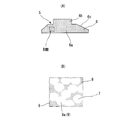
- FIG. 1 is an overhead view showing a cross section of a part of a piston used in a first embodiment of a piston manufacturing method for an internal combustion engine according to the present invention. It is the A section enlarged view shown in FIG. (A) is a longitudinal cross-sectional view of a porous member (low thermal conductivity member) provided for the present embodiment, and (B) is an enlarged view of part B shown in FIG. 3A.
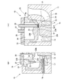
- A is sectional drawing which shows the piston manufacturing apparatus provided to this embodiment
- B is sectional drawing which shows a part of the piston manufacturing apparatus.
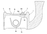
- It is sectional drawing of the piston base material taken out from the said piston manufacturing apparatus.
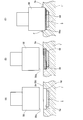
- FIG. 6 It is a figure which shows the detail of the principal part of FIG. 6, Comprising: (A) is front explanatory drawing, (B) is a plane explanatory drawing of the figure (A). The friction sealing process by the friction sealing apparatus of this embodiment is shown, (A) is a state where a rotary tool descends from above the low thermal conductivity member, (B) is a tip surface of the rotary tool on the upper surface of the low thermal conductivity member. (C) is an explanatory view showing a state in which the upper surface of the low thermal conductivity member is sealed with a rotary tool.
- (A) is the state which contact
- (B) is the 1st.
- (C) is the state where the low thermal conductivity member is sealed
- (D) is the tip surface of the second rotary tool.
- (E) shows a state in which the center portion of the low thermal conductivity member is sealed with the second rotary tool.
- the piston 1 as a whole is integrally cast with an AC8A Al—Si aluminum alloy as a base material, and is formed in a substantially cylindrical shape as shown in FIG. 1 to define a combustion chamber on the crown surface 2a.
- the crown portion 2 a pair of arc-shaped thrust side skirt portion 3a and anti-thrust side skirt portion 3b integrally provided on the outer peripheral edge of the lower end of the crown portion 2, and both circumferential sides of the skirt portions 3a and 3b And a pair of apron portions 4a and 4b connected to the ends via respective connecting portions.
- the apron portions 4a and 4a are integrally formed with pin boss portions 4b and 4b that support both ends of a piston pin (not shown).
- the crown part 2 has a disk shape formed with a relatively large thickness, and the crown surface 2a defining the combustion chamber has a convex outer peripheral part and a flat part with a large surface area in the central part.
- a recess 2b is formed.
- a low thermal conductivity member 5 having a lower thermal conductivity than the piston base material 1 ' is cast and fixed at a predetermined position on the upper surface of the recess 2b. Further, three piston ring grooves 2 c are formed on the outer periphery of the crown portion 2.
- the low thermal conductivity member 5 is a position in which the fuel is directly injected from the injector, which is a fuel injection valve provided in the cylinder head (not shown), in the recessed portion 2b.
- the porous member 6 made of a glass material having a lower thermal conductivity than the piston base material 1 ′ is integrally cast and fixed in the recess 2 b (at the time of casting). A part of the piston base material 1 ′ is impregnated inside during the casting.
- the low thermal conductivity member 5 is impregnated into the porous member 6 made of a glass material and many holes 9a after the water-soluble salt previously filled in the pores of the porous member 6 is dissolved. And an aluminum alloy material 1a which is a part of the base material 1 '.
- the first powder 8 that is basically powdered glass and the second powder that is a chlorinated compound are mixed and sintered.
- the first powder 8 is a glass powder, and is a hard and transparent substance mainly composed of silicate, borate, and phosphate, which is an amorphous solid that exhibits a glass transition phenomenon when heated. . Chemically, it is mainly a silicate compound (silicate mineral) that becomes glassy.
- silicate compound silicate mineral
- oxides constituting the glass SiO2, Al203, B203, BaO, Bi203, Li20, MgO, P205, PbO, SnO, TiO2, ZnO, R2O
- R is an abbreviation for alkali metals: Li, Na, K), RO (R is an alkaline earth metal; an abbreviation for Mg, Ca, Sr, Ba).
- the first powder 8 has a softening temperature (softening point) lower than the melting point of the second powder 9 and a melting point of 700 ° C. or higher.
- the transition point is the temperature at which the glass structure changes and has a viscosity of about 1013.3 poise.
- the softening point is a temperature at which the glass softens and deforms due to its own weight, and has a viscosity of about 107.6 poise.
- the second powder 9 is made of sodium chloride, potassium chloride, magnesium chloride, calcium chloride, calcium carbonate, sodium carbonate, sodium sulfate, magnesium sulfate, potassium sulfate, sodium nitrate, calcium nitrate, magnesium nitrate, potassium nitrate, Although water-soluble salts such as sodium borate, a mixed salt of one or two or more of them may be used.
- Sodium chloride and salts having a melting point exceeding 700 ° C. and water-soluble, such as potassium chloride, magnesium chloride, calcium chloride, calcium carbonate, sodium carbonate, sodium sulfate, magnesium sulfate, potassium sulfate, and sodium tetraborate are desirable. .
- the second powder 9 which is sodium chloride is mixed with the first powder 8 of borosilicate glass (ASF 1898 powder glass manufactured by Asahi Glass Co., Ltd.).
- the mixing ratio of the first powder 8 and the second powder 9 was set to 60 to 80% by volume for the second powder 9 and 40 to 20% by volume for the first powder.
- a mixed powder having a weight ratio of 54:46 (weight ratio) was mixed (mixing step).
- the particle diameter of each powder is set in the range of an average particle diameter of 4.5 ⁇ m for the first powder 8 and 850 to 1300 ⁇ m for the second powder 9, and the second powder 9 is composed of the particles of 850 to 1300 ⁇ m.
- the content ratio of the diameter is set in the range of 50 to 80%.
- the mixed powder is put into a mold and press-molded, and heated and baked at a temperature of 650 ° C. to 750 ° C. for 20 to 40 minutes. In this embodiment, it is heated at a temperature of 700 ° C. for 30 minutes. Thus, a sintered compact was obtained (firing step).
- the sintered compact is immersed in a stirred 55 ° C. hot water to dissolve the second powder 9 (sodium chloride) therein, and is extracted from the compact to form a porous member 6 having many pores 9a. Obtained (dissolution step).
- This melting step is performed in the range of 30 minutes to 3 hours with the second powder 9 in hot water of 50 ° C. to 95 ° C.
- the porous member 6 includes a disc-shaped base portion 6a and a small-diameter columnar projection portion 6b integrally provided on the upper surface of the base portion 6a. Is formed on the tapered surface 6c. Further, as shown in FIG. 3B, the porous member 6 is in a form in which the second powder 9 is almost dissolved and disappears, and the first powder 8 (glass) remains. A large number of holes 9 a are formed around 8.
- the glass powder is surrounded around the sodium chloride particles.
- the porous member 6 is formed differently depending on the mixing ratio of the first powder 8 and the second powder 9.
- the glass powder when the sodium chloride powder is 80% by volume or more and the glass powder is 20% by volume or less, the glass powder is not melt-bonded by heating. When it is melted with hot water, the molded body collapses.
- the glass powders are easily melted and joined by heating to cover the periphery of the sodium chloride powder. Accordingly, when the sodium chloride powder is melted with subsequent water or hot water, the sodium chloride powder cannot be contacted with water or hot water, and the porous member 6 cannot be molded.
- sodium chloride powder When sodium chloride powder is 50 to 80% by volume and glass powder is 50 to 20% by volume, open pores 9a (holes connected from the surface to the inside) are obtained.
- the sodium chloride powder is not completely melted out, and a part of the sodium chloride powder is covered with glass powder and is in a closed state.
- the amount of the sodium chloride powder in the closed state is determined by the mixing ratio of the sodium chloride powder (second powder 9) and the glass powder (first powder 8).
- sodium chloride (2nd powder 9) is 80 volume%, there will be no remaining sodium chloride by melt
- the second powder 9 is 60% by volume, the remaining sodium chloride powder is 25% by volume.
- the remaining sodium chloride powder is surrounded by the glass powder of the first powder 8 and functions as a heat insulating material.
- the obtained porous member 6 is impregnated with a piston casting alloy (aluminum alloy 1a) described later. Thereafter, the impregnated portion is cut and finished, and sodium chloride remaining on the processed surface appears.
- the processed surface becomes a composite structure of glass as the porous member 6 and the cast alloy of the piston base material 1 ′, and the dissolved amount increases as the amount of sodium chloride powder increases.
- the surface area increases due to an increase in surface irregularities.
- the remaining sodium chloride increases as the volume ratio of the sodium chloride decreases.
- the porous member 6 mainly composed of the first powder 8 (glass) is disposed in the vacuum casting mold 10 for molding the piston 1.
- the decompression casting mold 10 is the same as that described in Japanese Patent Laid-Open No. 2014-25418, and will be briefly described with reference to FIGS. 4A and 4B.
- the mold 10 includes a mold 11 in which a center core 12 and a plurality of divided cores such as a lip core 13 and a side core 14 disposed around the center core 12 are combined.
- a core 15 is provided on the lower side.
- the mold 10 is horizontally provided with a pair of left and right wrist pins 16 that form a cooling path for circulating cooling water therein.
- the mold 10 has a mold bush 17 for supporting the wrist pin 16, and a top core 19 detachable from the mold 11 is provided on the upper side.
- the top core 19 includes an outer top core 21 having a space as an example of the suction / discharge portion 20, and an inner top core 23 provided integrally with the outer top core 21.
- the outer top core 21 is provided with an adapter 25 for sealing the suction / discharge portion 20 at an upper end portion, and a pipe-shaped first communication pipe 27 is provided at substantially the center of the adapter 25.
- the first communication pipe 27 communicates with the suction / discharge section 20 and is connected to negative pressure generating means such as a vacuum pump (not shown).
- the inner top core 23 is provided to face the core 15 and forms a cavity 29 between the core 15 and the mold 11. Moreover, this inner top core 23 is comprised by the air permeable metal mold
- the cavity surface 23 ⁇ / b> A of the inner top core 23 facing the core 15 is formed when the piston 1 as a product is molded by pouring (melting) molten aluminum alloy into the cavity 29. It is formed on a transfer surface for transferring the crown surface 2a.
- the cavity surface 23A is formed on the finished surface by electric discharge machining.
- the metal powder particles may be crushed and block the pores between the particles. In other words, the air permeability of the pores between the powder particles is well maintained.
- the inner top core 23, the suction / discharge section 20, and the adapter 25 are located at positions corresponding to the portions where the concave portions 2b of the crown surface 2a of the inner top core 23 are formed.
- the second communication pipe 30 is connected to a negative pressure generating means such as a vacuum pump (not shown) at the upper end portion in the same manner as the first communication pipe 27. Therefore, by operating the negative pressure generating means, the inside of the porous member 6 previously held in the holding groove 31 is depressurized to be negative pressure, and a large number of holes 9a are impregnated with molten aluminum described later. It is like that.
- a negative pressure generating means such as a vacuum pump (not shown) at the upper end portion in the same manner as the first communication pipe 27. Therefore, by operating the negative pressure generating means, the inside of the porous member 6 previously held in the holding groove 31 is depressurized to be negative pressure, and a large number of holes 9a are impregnated with molten aluminum described later. It is like that.
- the inner top core 23 is configured to be a porous type
- the suction / discharge section 20 has a negative pressure
- the gas in the cavity 29 is sucked through the inner top core 23. It will be sucked by 20 and discharged to the outside. Further, the molten aluminum alloy poured into the cavity 29 is sucked into and directly contacts the cavity surface 23A (transfer surface) of the inner top core 23, and the shape of the cavity surface 23A is transferred as it is. Become.
- the mold 11 is provided with a runner 32 for supplying molten metal to the cavity 29, and the runner 32 communicates with the lower side of the cavity 29.
- the inside of the porous member 6 is reduced to a negative pressure through the second communication pipe 30 by the vacuum pump.
- the molten metal supplied into the cavity 29 is directly brought into suction contact with the cavity surface 23A (transfer surface) of the inner top core 23 due to the negative pressure of the suction / discharge section 20 and is brought into close contact therewith.
- the decompression motor (not shown) is driven to discharge the air in the suction / discharge section 20 and suck the suction.
- the discharge part 20 is decompressed.
- the gas in the cavity 29 passes through the pores of the air-permeable mold (porous mold) 23 and is discharged to the outside.
- the suction and discharge part 20 is depressurized so that the molten metal is attracted and adhered to the cavity surface 23A.
- the unevenness of the cavity surface 23A is transferred to the crown surface of the piston, and the portion 23B of the recess 23C of the cavity surface 23A corresponding to the convex portion of the piston crown surface is Since it is formed thinner than the other parts, the molten metal is attracted and adhered more effectively to this part, and even the part where the shape of the piston crown surface 2a is difficult to be formed can be formed with high accuracy. .
- the inside of the porous member 6 has a negative pressure, a part of the molten aluminum in the cavity 29 is sucked into the porous member 6 and a large number of holes 9a in which sodium chloride is dissolved. It penetrates and fills inside.
- the low heat transfer coefficient portion 5 impregnated with the same aluminum alloy material 1a as the piston base material 1 ' is embedded and fixed integrally with the base material 1'.
- the air holes 9a are filled with the aluminum alloy material 1a, but the second powder 9 (sodium chloride) remains slightly.
- the piston base material 1 ′ in which the low thermal conductivity member 5 is integrated is taken out from the cooled vacuum casting mold 10 and formed on the outer peripheral surface of the piston base material 1 ′ as shown in FIG. A primary machine that cuts the casting burr and the piston ring groove 2c and cuts the protrusion 6b and the upper surface of the base 6a of the low thermal conductivity member 5 (porous member 6) to form the same surface as the crown surface 2a. Processing (cutting process). [Sealing treatment of the top surface of low conductivity members] Then, after the primary machining is completed, the pores 9a existing on the surface of the low thermal conductivity member 5 are sealed by the friction sealing device shown in FIGS. 6 to 8 (friction sealing step).
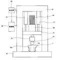
- FIG. 6 shows a schematic structure of a friction sealing device for sealing the holes 9a on the surface of the low thermal conductivity member 5 by friction.
- This friction sealing device uses a known equipment for friction stir welding, and the piston 1 as a workpiece is positioned on the bed 40, and the cross head facing the bed 40 is used. 41 is supported by a gate-type gantry 42 so as to be movable up and down.
- a solid cylindrical rotating tool (tool or probe) 44 for friction sealing is mounted downward on the cross head 42 via a tool holder 43.
- the rotary tool 44 is rotationally driven via an electric motor 45 and a speed reduction mechanism 46 on the cross head 42, and the electric motor 45 and the speed reduction mechanism 46 constitute a rotation mechanism.
- the entire cross head 42 including the rotary tool 44 is driven up and down by a hydraulic cylinder 47 as a moving mechanism.
- the friction sealing device is provided with a control panel 49 in addition to the hydraulic power source 48.
- the rotary tool 44 has a circular flat surface whose tip surface 44 a is slightly larger than the diameter of the low thermal conductivity member 5.
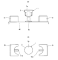
- FIGS. 6A and 6B show details of a mechanism for positioning the piston 1 on the bed 40 in the friction sealing device shown in FIG. 6, wherein FIG. 7A is an explanatory front view, and FIG. The plane explanatory drawing of each is shown.
- FIGS. 6A and 6B when the piston 1 is positioned and clamped on the bed 40, the piston 1 is placed on the center jig 50 on the bed 40 and is concavo-convexly fitted.
- the pair of left and right side jigs 51 having a projection 51a that can be inserted into the pin hole on the piston 1 side is moved forward by a hydraulic cylinder (not shown), and the pair of left and right sides are supported.
- the left and right side jigs 51 and hydraulic cylinders constitute a holding mechanism (holding process).
- the tip end surface 44a is pressed against the entire upper surface 5a of the low thermal conductivity member 5 so as to block the entire upper surface 5a.
- the circular tip surface 44 a of the rotary tool 44 is formed to be slightly larger than the upper surface 5 a of the low thermal conductivity member 5.
- the rotary tool 44 may be in a rotational form in which the rotary tool 44 moves to its axis.
- the load is unloaded when a specified load (for example, 5 tons), pushing amount and friction torque is reached, and the rotating tool 44 is lifted to rotate the rotating tool 44. stop.
- a specified load for example, 5 tons
- the plastic fluidized bed 5b is formed on the entire upper surface 5a of the low thermal conductivity member 5 by frictional heat between the tip surface 44a of the rotary tool 44 and the upper surface 5a of the low thermal conductivity member 5. As a result, the opening of each hole 9a formed in the upper surface 5a is sealed.
- Various conditions such as the rotational speed and frictional torque of the rotary tool 44 are the silicate compound that is the glass on the upper surface 5a of the low thermal conductivity member 5 (porous member 6) and the aluminum alloy that is the base material 1 ′ of the piston 1.
- the plastic fluidized bed 5b is formed by softening the material by frictional heat.
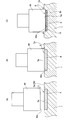
- FIG. 8 is a detailed view of the process of the friction sealing process.
- FIG. 8A is a front end surface 44a of the rotary tool 44 with respect to the upper surface 5a of the low thermal conductivity member 5 of the piston 1 held in advance in a predetermined position.
- FIG. 5B shows a state in which the tip surface 44a of the rotary tool 44 is in contact with the entire upper surface 5a of the low thermal conductivity member 5 and the periphery thereof.
- FIG. 5C shows that the rotary tool 44 is pushed to a specified amount with respect to the upper surface 5a of the low thermal conductivity member 5, and a plastic fluidized bed 5b is formed on the upper surface 5a of the low thermal conductivity member 5, thereby forming each hole 9a. Indicates a sealed state.
- the surface of the low thermal conductivity member 5 is flush with the base material 1 ′ of the piston 1 so as to eliminate the recess around the low thermal conductivity member 5 formed by pushing the rotary tool 44. Since cutting is performed so as to be in a state, even “kaeri” F is simultaneously cut and removed.
- the relationship between the diameter of the upper surface 5a of the low thermal conductivity member 5 and the diameter of the tip surface 44a of the rotary tool 44 may be any as long as the diameter of the tip surface 44a of the rotary tool 44 exceeds the diameter of the upper surface 5a.
- the diameter of the tool 44 is desirably about 1 mm larger than the diameter of the low thermal conductivity member 5.
- the shape of the low thermal conductivity member 5 is not necessarily circular, but when the rotary tool 44 is circular, the low thermal conductivity member 5 is also preferably circular.
- the circular plastic fluidized bed 5b is formed on the upper surface 5a of the low thermal conductivity member 5 by rotating the rotary tool 44 under various conditions such as the aforementioned load, rotational torque, and rotational speed.
- the rotary tool 44 under various conditions such as the aforementioned load, rotational torque, and rotational speed.
- the cross sectional area of the first rotary tool 54 is slightly larger than the outer diameter of the low thermal conductivity member 5 as in the first embodiment.
- the tip is formed in a hollow cylindrical shape and the tip surface 54a of the tip is formed in an annular shape.
- the outer diameter of the tip surface 55 a of the tip part is the outer diameter of the tip part of the first rotary tool 54 or the low thermal conductivity member 5. Sealing treatment is performed using a cylindrical member that is slightly smaller than the outer diameter of the center portion 5c described later.
- the annular tip surface 54 a is applied to the upper surface 5 a of the low thermal conductivity member 5 using the first rotary tool 54 under the above-described conditions such as a predetermined load and rotational torque.
- the annular plastic fluidized bed 5b is formed by being pressed and softened by frictional heat. Therefore, as shown in FIG. 9C, the opening portions of the air holes 9a located in the annular region on the outer peripheral side of the upper surface 5a of the low thermal conductivity member 5 are sealed.
- the central portion 5c of the low thermal conductivity member 5 that has not been subjected to the sealing treatment is raised in a cylindrical shape.
- the first rotary tool 54 is replaced with the second rotary tool 55, and as shown in FIGS. 9D and 9E, the tip surface 55a of the second rotary tool 55 is raised to the raised central portion 5c of the low thermal conductivity member 5.
- a portion where the second rotary tool 55 is rotated from above at a position slightly deviated radially outward from the central portion 5c to the upper surface of the upper portion, and the second portion of the second rotating tool 55 is already formed on the outer peripheral side with the central portion 5c. Rotate to draw a circle while straddling.
- the same plastic fluidized bed 5b as the outer peripheral plastic fluidized bed 5b is formed by frictional heat on the upper surface of the central portion 5c.
- the reason why the first rotary tool 54 is replaced with the second rotary tool 55 and the sealing process is performed in two stages is that the rotary tool 44 is used when the single rotary tool 44 is used as in the first embodiment.
- the plastic fluidized bed 5b is first formed on the outer peripheral side having a large peripheral speed 44, and the sealing process proceeds.
- the rotary tool 44 is simply rotated. If only the rotation speed and the load are increased, the speed of the central portion of the low thermal conductivity member 5 is decreased, and an unplastic fluidized bed is generated, and a sufficient sealing effect may not be obtained. .
- the plastic fluidized bed 5b can be formed on the entire upper surface 5a of the low thermal conductivity member 5. Therefore, an effective sealing process can be performed.
- FIG. 10 and 11 show a third embodiment.
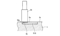
- one rotating tool 56 is rotated on the upper surface 5a of the low thermal conductivity member 5 by using a moving mechanism (not shown). It is made to move while spiraling.
- the rotary tool 56 is formed such that the outer diameter of the tip end surface 56a is sufficiently smaller than the outer diameter of the low thermal conductivity member 5, and the tip end surface 56a is moved over the upper surface 5a of the low thermal conductivity member 5 by the moving mechanism. It is made to move spirally from the outer peripheral side to the center side.
- the spiral movement trajectory M is spiral from the outer peripheral side to the inner peripheral side (center side) so that the tip surface 56a of the rotary tool 56 partially overlaps inside and outside.
- the outer peripheral edge side of the upper surface 5a of the low thermal conductivity member 5 moves in a state of covering the entire outer peripheral edge.
- the uniform plastic fluidized bed 5c is formed on the entire upper surface 5a by moving one rotary tool 56 spirally from the outer peripheral side to the center side on the upper surface 5a of the low thermal conductivity member 5. can do. That is, since the tip end surface 56a of the rotary tool 56 having a smaller area than the upper surface 5a of the low thermal conductivity member 5 is moved while being plastically fluidized and spread over the whole, a uniform plastic fluidized bed 5c is formed throughout. can do.
- the pressing area of the rotary tool 56 is small, it can be performed with a small load, and the apparatus can be miniaturized.
- FIG. 12 shows a fourth embodiment.
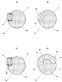
- the rotary tool 57 is moved up and down in a stamping manner with respect to the upper surface 5a of the low thermal conductivity member 5, and from the outer peripheral side so as to draw a circle while repeating the stamping motion. It is configured to move to the inner peripheral side (center side).
- the rotary tool 57 has an outer diameter that is sufficiently smaller than that of the upper surface 5a of the low thermal conductivity member 5 as in the third embodiment, and a tip surface by a stamping mechanism that is a moving mechanism outside the figure. 40a, the upper surface 5a of the low thermal conductivity member 5 is pressed once while rotating, then once lifted and moved in the circumferential direction so that the central portion 5d of the pressed portion overlaps, and further lowered and pressed here The work is performed, and the plastic fluidized bed 5b is formed on the entire upper surface 5a of the low thermal conductivity member 5 by performing plastic fluidization in a small circular shape sequentially while repeating the stamping motion in the circumferential direction and the movement in the circumferential direction. It is like that.
- the rotary tool 57 is pressed once while rotating in a state straddling the crown surface 2a on the outer peripheral side of the low thermal conductivity member 5, and a circular shape is formed at this portion.
- the plastic fluidized bed 5b is formed.
- the rotary tool 57 is once lifted and moved in the circumferential direction by a predetermined amount, and as shown in FIG. And rotate while pressing the upper surface 5a.
- the next circular plastic fluidized bed 5b is formed.
- the circular plastic fluidized bed 5b is formed on the entire outer peripheral portion of the low thermal conductivity member 5 while sequentially repeating the stamping motion and the circumferential movement described above.
- the rotary tool 57 is moved inward to a position where a part of the annular plastic fluidized bed 5b of the outer periphery is covered.
- the same stamping motion and movement in the circumferential direction as described above are repeated to form the annular plastic fluidized bed 5b, and then a series of stamping motion and movement in the circumferential direction are further repeated on the inner circumferential side.
- the rotary tool 57 is moved by the stamping method instead of sliding on the upper surface 5a of the low thermal conductivity member 5, the upper surface 5a of the low thermal conductivity member 5 is used.
- the plastic fluidized bed 5b can be effectively formed on the whole.
- the rotary tool 57 can be set small, it can be performed with a small load, and the stirring conditions of the friction stirring portion can be made the same.
- the stamping motion is not affected by burrs generated around the range where the rotary tool 57 is pressed, the reliability is improved.
- FIG. 13 shows a fifth embodiment in which a circular groove 2d which is a recess larger than the outer diameter of the low thermal conductivity member 5 is formed on the upper surface side of the low thermal conductivity member 5 embedded in the crown surface 2a.
- the inside of the circular groove 2d is filled with, for example, an aluminum alloy powder 59 of the same material as the piston base material 1 ′, and then this aluminum alloy powder 59 is pressed against the flat circular tip surface 58a of the rotary tool 58 and rotated.
- the low thermal conductivity member 5 is friction-bonded to the upper surface 5a.
- the low thermal conductivity portion 5 described above is integrally embedded in the crown surface 2a, and then the circular groove 2d is formed on the upper surface 5a side of the low thermal conductivity member 5. For example by machining. The entire upper surface 5a of the low thermal conductivity member 5 is exposed on the bottom surface side of the circular groove 2d.
- the circular groove 2d can be formed together with the fixing of the low thermal conductivity member 5 (porous member 6) using a circular core during piston casting.
- the inside of the circular groove 2d is filled with the aluminum alloy powder 59. Then, as shown in FIG. By pressing and rotating the flat front end surface 58a, the aluminum alloy powder 59 is frictionally bonded to the upper surface 5a of the low thermal conductivity member 5 to form a lid-like aluminum alloy surface layer 60. Each opening of the hole 9a can be sealed.
- the aluminum alloy powder 59 enters the pores 9a by directly friction-joining the aluminum alloy powder 59 to the upper surface 5a of the low thermal conductivity member 5, and thus more effective.
- each hole 9a can be sealed.
- the circular groove 2d is filled with the aluminum alloy powder 59.
- an aluminum alloy material previously formed in a disk shape can be accommodated and disposed. It is.
- the present invention is not limited to the configuration of the embodiment, and for example, the components of the first powder 8 and the second powder 9 can be arbitrarily changed according to the material components of the piston 1 and the like. is there.
- the shape of the tip surfaces 44a, 54a, 55a, 56a, 57a of the rotary tools 44, 54, 55, 56, 57 is not limited to a flat shape, and may be a curved surface.
Landscapes
- Engineering & Computer Science (AREA)
- Mechanical Engineering (AREA)
- Chemical & Material Sciences (AREA)
- Combustion & Propulsion (AREA)
- General Engineering & Computer Science (AREA)
- Pistons, Piston Rings, And Cylinders (AREA)
- Pressure Welding/Diffusion-Bonding (AREA)
Abstract
Description
成形金型の内部所定位置に前記多孔質部材を配置した後に、前記金型内に溶湯を注入して前記多孔質部材の各空孔内に含浸させて前記低熱伝導率部材を固定するピストンを成形するピストン成形工程と、
前記ピストンを冷却した後に、前記金型内から取り出された前記ピストンの低熱伝導率部材の表面に、回転工具を押し当てて前記多孔質部材表面の空孔を摩擦熱により封孔処理を行う摩擦封孔工程と、
を備えたことを特徴としている。
以下、多孔質部材6の具体的な製造方法について説明すると、基本的に粉末ガラスである第1粉体8と、塩化化合物である第2粉体を混合して焼結させることによって成形する。
〔ピストンの鋳造金型装置〕
前記減圧鋳造用金型10は、前記特開2014-25418号公報に記載されたものと同じであるから、図4A、Bに基づいて簡単に説明する。
したがって、前記金型10を用いてピストン1を鋳造するには、前記モールド型11の湯道32からキャビティ29内へアルミ合金の溶湯を注入すると共に、吸引排出部20内を負圧にする。したがって、キャビティ29内の気体の排出を効果的に行うことができるものである。
〔低伝導率部材上面の封孔処理〕
そして、前記一次機械加工が終了した後に、図6~図8に示す摩擦封孔装置によって前記低熱伝導率部材5の表面に存在する空孔9aの封孔処理を行う(摩擦封孔工程)。
〔第2実施形態〕
図9A~図9Eは第2実施形態を示し、回転工具を2つの種類のものを用意し、前記低熱伝導率部材5の上面5aに対して2段階に分けて封孔処理を行うようにしたものである。
〔第3実施形態〕
図10及び図11は第3実施形態を示し、この実施形態では、前記回転機構の他に、図外の移動機構を用いて一つの回転工具56を、低熱伝導率部材5の上面5aで回転させながら渦巻き状に移動させるようにしたものである。
〔第4実施形態〕
図12は第4実施形態を示し、この実施形態では回転工具57を低熱伝導率部材5の上面5aに対してスタンピング状に上下移動させると共に、スタンピング運動を繰り返しながら円を描くように外周側から内周側(中心側)へ移動するように構成したものである。
〔第5実施形態〕
図13は第5実施形態を示し、前記冠面2aの内部に埋設された低熱伝導率部材5の上面側に、該低熱伝導率部材5の外径よりも大きな凹部である円形溝2dを形成し、該円形溝2dの内部に、例えばピストン母材1’同じ材質のアルミニウム合金粉末59を充填し、その後、このアルミニウム合金粉末59を回転工具58の平坦な円形状の先端面58aで押し付け回転させて低熱伝導率部材5の上面5aに摩擦接合させるようにしたものである。
Claims (18)
- ピストンの冠面に、前記ピストン母材よりも熱伝導率の低い多孔質部材を用いた低熱伝導率部材が設けられた内燃機関のピストンの製造方法であって、
前記多孔質部材の空孔内に溶湯を含浸させてなる前記低熱伝導率部材が前記冠面に設けられた状態で前記ピストンを保持する工程と、
前記ピストンが保持された状態で前記低熱伝導率部材の表面に、回転工具を押し当てて前記多孔質部材表面の空孔を摩擦熱により封孔処理を行う摩擦封孔工程と、
を備えたことを特徴とする内燃機関のピストン製造方法。 - 請求項1に記載の内燃機関のピストン製造方法であって、
前記摩擦封孔工程では、前記回転工具を前記多孔質材の表面に対して押し当てる位置を移動させながら封孔処理を行うことを特徴とする内燃機関用ピストンの製造方法。 - 請求項2に記載の内燃機関のピストン製造方法であって、
前記摩擦封孔工程は、前記回転工具を前記低熱伝導率部材の表面に対してスタンピング状に移動させながら押し当てて封孔処理を行うことを特徴とする内燃機関のピストン製造方法。 - 請求項3に記載の内燃機関のピストン製造方法であって、
前記回転工具をスタンピング状に移動させる際には、前記回転工具の先端面外周部を、先に封孔処理された部位の中央部にかかるように移動させたことを特徴とする内燃機関のピストン製造方法。 - 請求項4に記載の内燃機関のピストン製造方法であって、
前記摩擦封孔工程は、前記低熱伝導率部材の表面全体を封孔処理することを特徴とする内燃機関のピストン製造方法。 - 請求項5に記載の内燃機関用ピストンの製造方法であって、
前記摩擦封孔工程は、前記低熱伝導率部材の表面を中央から外側に渦巻き状に移動することを特徴とする内燃機関用ピストンの製造方法。 - 請求項2の記載の内燃機関のピストン製造方法であって
前記摩擦封孔工程は、前記回転工具の先端面を前記低熱伝導率部材の表面に押付けながら連続的に摺動移動させて封孔処理を行うことを特徴とする内燃機関のピストン製造方法。 - 請求項7に記載の内燃機関のピストン製造方法であって、
前記摩擦封孔工程は、前記回転工具の先端面を前記低熱伝導率部材の表面全体を連続的に摺動移動させて封孔処理を行うことを特徴とする内燃機関のピストン製造方法。 - 請求項8に記載の内燃機関のピストン製造方法であって、
前記摩擦封孔工程は、前記回転工具の先端面を前記低熱伝導率部材の表面の中央側から外側へ、あるいは外側から中央側に渦巻き状に摺動移動させて封孔処理を行うことを特徴とする内燃機関のピストン製造方法。 - 請求項1に記載の内燃機関のピストン製造方法であって、
摩擦封孔工程は、最初に、前記回転工具の円環状に形成された先端面によって前記低熱伝導率部材の表面の外周部を封孔処理し、
その後、前記回転工具の先端面よりも小径な円形状の先端面を有する別の回転工具で、前記低熱伝導率部材の表面の残りの中央部に封孔処理を行うことを特徴とする内燃機関のピストン製造方法。 - 請求項1に記載の内燃機関のピストン製造方法において、
前記摩擦封孔工程の後に、前記低熱伝導率部材の表面を切削加工する切削工程を有することを特徴とする内燃機関のピストン製造方法。 - 請求項1に記載の内燃機関のピストン製造方法であって、
前記多孔質部材は、ピストン母材と同じ金属粉末材と該金属粉末材よりも熱伝導率の低いガラス粉末材とを融合させた金属成形体によって構成されていることを特徴とする内燃機関のピストン製造方法。 - 請求項1に記載の内燃機関のピストン製造方法であって、
前記摩擦封孔工程は、前記回転工具の先端面で前記低熱伝導率部材の表面全体を覆った状態で回転させて封孔処理を行うことを特徴とする内燃機関のピストン製造方法。 - 請求項1に記載の内燃機関用ピストンの製造方法であって、
前記回転工具は、先端面が平面状に形成されていることを特徴とする内燃機関用ピストンの製造方法。 - 請求項1に記載の内燃機関用ピストンの製造方法であって、
前記低熱伝導部材は、成形金型の内部所定位置に前記多孔質部材を配置した後に、前記金型内に溶湯を注入して前記多孔質部材の各空孔内に含浸させて前記低熱伝導率部材を固定することを特徴とする内燃機関用ピストンの製造方法。 - ピストンの冠面付近の内部に、該ピストンの母材よりも熱伝導率の低い多孔質部材の各空孔内にピストン母材の溶湯を含浸させて低熱伝導率部材を固定するピストン成形工程と、
前記ピストン冠面の前記低熱伝導率部材が位置する部位に、該低熱伝導率部材の上面全体が露出するように凹部を形成する凹部形成工程と、
前記凹部内の低熱伝導率部材の上面にピストン母材とほぼ同材質の封止材を配置する封止材配置工程と、
前記封止材の上面に回転工具を押し当てて前記封止材を摩擦熱によって軟化させることにより前記低熱伝導率部材の表面の空孔を封止する摩擦封止工程と、
を備えたことを特徴とする内燃機関のピストン製造方法。 - ピストンの冠面に、前記ピストン母材よりも熱伝導率の低い多孔質部材を用いた低熱伝導率部材が設けられた内燃機関用ピストンの摩擦封孔装置であって、
前記冠面に前記低熱伝導率部材が設けられたピストンを保持する保持機構と、
先端面を前記低熱伝導率部材の表面に押し当てながら回転することによって摩擦熱を発生させて封孔処理を行う回転機構と、
前記回転機構の回転工具、または前記ピストン自体を前記空孔の封止処理可能な所定の位置に移動させる移動機構と、
を備えたことを特徴とする内燃機関用ピストンの摩擦封孔装置。 - 請求項17に記載の内燃機関用ピストンの摩擦封孔装置において、
前記移動機構は、前記回転工具の先端面によって前記低熱伝導率部材表面の空孔に封孔処理を行った後に、前記回転工具を前記表面から一旦に離間させて再度別の位置にスタンピング状に移動させながら封孔処理を行うことを特徴とするピストンの摩擦封孔装置。
Priority Applications (3)
| Application Number | Priority Date | Filing Date | Title |
|---|---|---|---|
| US15/519,875 US20170241372A1 (en) | 2014-10-21 | 2015-10-13 | Method for manufacturing piston for internal combustion engine and frictional hole sealing device for piston for internal combustion engine |
| CN201580048763.6A CN107076050A (zh) | 2014-10-21 | 2015-10-13 | 内燃机的活塞制造方法以及内燃机用活塞的摩擦封孔装置 |
| JP2016555180A JP6232504B2 (ja) | 2014-10-21 | 2015-10-13 | 内燃機関のピストン製造方法および内燃機関用ピストンの摩擦封孔装置 |
Applications Claiming Priority (2)
| Application Number | Priority Date | Filing Date | Title |
|---|---|---|---|
| JP2014-214113 | 2014-10-21 | ||
| JP2014214113 | 2014-10-21 |
Publications (1)
| Publication Number | Publication Date |
|---|---|
| WO2016063754A1 true WO2016063754A1 (ja) | 2016-04-28 |
Family
ID=55760798
Family Applications (1)
| Application Number | Title | Priority Date | Filing Date |
|---|---|---|---|
| PCT/JP2015/078863 Ceased WO2016063754A1 (ja) | 2014-10-21 | 2015-10-13 | 内燃機関のピストン製造方法および内燃機関用ピストンの摩擦封孔装置 |
Country Status (4)
| Country | Link |
|---|---|
| US (1) | US20170241372A1 (ja) |
| JP (1) | JP6232504B2 (ja) |
| CN (1) | CN107076050A (ja) |
| WO (1) | WO2016063754A1 (ja) |
Cited By (4)
| Publication number | Priority date | Publication date | Assignee | Title |
|---|---|---|---|---|
| JP2019120310A (ja) * | 2017-12-28 | 2019-07-22 | 本田技研工業株式会社 | 動力伝達装置の部材接合構造 |
| JP2020133492A (ja) * | 2019-02-20 | 2020-08-31 | 日立オートモティブシステムズ株式会社 | 内燃機関のピストンおよびその製造方法 |
| CN113290105A (zh) * | 2021-05-19 | 2021-08-24 | 夏李送 | 一种机械加工用的固定效果更佳且易脱离的冲压辅助装置 |
| JP2025136276A (ja) * | 2024-03-07 | 2025-09-19 | 本田技研工業株式会社 | 摩擦攪拌接合装置、および摩擦撹拌接合方法 |
Families Citing this family (2)
| Publication number | Priority date | Publication date | Assignee | Title |
|---|---|---|---|---|
| CN109048037B (zh) * | 2018-08-23 | 2020-12-01 | 常熟理工学院 | 基于搅拌摩擦加工制备Al-Pb合金耐磨层的方法 |
| CN109570631B (zh) * | 2018-12-21 | 2021-04-20 | 西安建筑科技大学 | 一种搅拌摩擦加工制备多孔金属材料的方法及其加工装置 |
Citations (8)
| Publication number | Priority date | Publication date | Assignee | Title |
|---|---|---|---|---|
| JPH10183316A (ja) * | 1996-12-25 | 1998-07-14 | Showa Alum Corp | アルミニウム鋳物材の表面改質法 |
| JPH11193721A (ja) * | 1997-10-30 | 1999-07-21 | Toyota Central Res & Dev Lab Inc | 筒内噴射式火花点火機関 |
| JP2002096158A (ja) * | 2000-09-21 | 2002-04-02 | Nippon Light Metal Co Ltd | 鋳物表面の微細空隙除去方法およびこれに用いる攪拌ツール |
| JP2003048064A (ja) * | 2001-08-01 | 2003-02-18 | Mazda Motor Corp | 表面処理方法、表面処理装置並びに当該表面処理が施された部材 |
| JP2005324240A (ja) * | 2004-05-17 | 2005-11-24 | Ryobi Ltd | アルミニウム鋳物材の表面改質法及びアルミニウム鋳物材の外観不良補修法 |
| JP2009264236A (ja) * | 2008-04-24 | 2009-11-12 | Toyota Motor Corp | 内燃機関のピストン及びその製造方法 |
| WO2015016122A1 (ja) * | 2013-08-01 | 2015-02-05 | 日立オートモティブシステムズ株式会社 | 内燃機関用ピストンの製造方法および内燃機関用ピストン |
| JP2015218608A (ja) * | 2014-05-15 | 2015-12-07 | 日産自動車株式会社 | ピストンおよびその製造方法 |
Family Cites Families (2)
| Publication number | Priority date | Publication date | Assignee | Title |
|---|---|---|---|---|
| CN101952079B (zh) * | 2008-02-21 | 2014-04-02 | 日本轻金属株式会社 | 传热板的制造方法 |
| JP5337142B2 (ja) * | 2010-12-28 | 2013-11-06 | 日立オートモティブシステムズ株式会社 | 内燃機関のピストンと該ピストンの製造法及び摺動部材 |
-
2015
- 2015-10-13 US US15/519,875 patent/US20170241372A1/en not_active Abandoned
- 2015-10-13 CN CN201580048763.6A patent/CN107076050A/zh active Pending
- 2015-10-13 WO PCT/JP2015/078863 patent/WO2016063754A1/ja not_active Ceased
- 2015-10-13 JP JP2016555180A patent/JP6232504B2/ja not_active Expired - Fee Related
Patent Citations (8)
| Publication number | Priority date | Publication date | Assignee | Title |
|---|---|---|---|---|
| JPH10183316A (ja) * | 1996-12-25 | 1998-07-14 | Showa Alum Corp | アルミニウム鋳物材の表面改質法 |
| JPH11193721A (ja) * | 1997-10-30 | 1999-07-21 | Toyota Central Res & Dev Lab Inc | 筒内噴射式火花点火機関 |
| JP2002096158A (ja) * | 2000-09-21 | 2002-04-02 | Nippon Light Metal Co Ltd | 鋳物表面の微細空隙除去方法およびこれに用いる攪拌ツール |
| JP2003048064A (ja) * | 2001-08-01 | 2003-02-18 | Mazda Motor Corp | 表面処理方法、表面処理装置並びに当該表面処理が施された部材 |
| JP2005324240A (ja) * | 2004-05-17 | 2005-11-24 | Ryobi Ltd | アルミニウム鋳物材の表面改質法及びアルミニウム鋳物材の外観不良補修法 |
| JP2009264236A (ja) * | 2008-04-24 | 2009-11-12 | Toyota Motor Corp | 内燃機関のピストン及びその製造方法 |
| WO2015016122A1 (ja) * | 2013-08-01 | 2015-02-05 | 日立オートモティブシステムズ株式会社 | 内燃機関用ピストンの製造方法および内燃機関用ピストン |
| JP2015218608A (ja) * | 2014-05-15 | 2015-12-07 | 日産自動車株式会社 | ピストンおよびその製造方法 |
Cited By (5)
| Publication number | Priority date | Publication date | Assignee | Title |
|---|---|---|---|---|
| JP2019120310A (ja) * | 2017-12-28 | 2019-07-22 | 本田技研工業株式会社 | 動力伝達装置の部材接合構造 |
| JP2020133492A (ja) * | 2019-02-20 | 2020-08-31 | 日立オートモティブシステムズ株式会社 | 内燃機関のピストンおよびその製造方法 |
| CN113290105A (zh) * | 2021-05-19 | 2021-08-24 | 夏李送 | 一种机械加工用的固定效果更佳且易脱离的冲压辅助装置 |
| JP2025136276A (ja) * | 2024-03-07 | 2025-09-19 | 本田技研工業株式会社 | 摩擦攪拌接合装置、および摩擦撹拌接合方法 |
| JP7762751B2 (ja) | 2024-03-07 | 2025-10-30 | 本田技研工業株式会社 | 摩擦攪拌接合装置、および摩擦撹拌接合方法 |
Also Published As
| Publication number | Publication date |
|---|---|
| JP6232504B2 (ja) | 2017-11-15 |
| CN107076050A (zh) | 2017-08-18 |
| US20170241372A1 (en) | 2017-08-24 |
| JPWO2016063754A1 (ja) | 2017-07-06 |
Similar Documents
| Publication | Publication Date | Title |
|---|---|---|
| JP6232504B2 (ja) | 内燃機関のピストン製造方法および内燃機関用ピストンの摩擦封孔装置 | |
| JP5976941B2 (ja) | 内燃機関用ピストンの製造方法 | |
| JP5859395B2 (ja) | 内燃機関のピストン及びこのピストンの製造方法 | |
| US10035731B2 (en) | Additive manufacturing hybrid core | |
| CN105142850B (zh) | 单塑料活塞激光焊接溅落的控制 | |
| CN208132744U (zh) | 具有内流道结构的固结金属结合剂砂轮及其制造装置 | |
| CN107008862A (zh) | 一种具有裂纹缺陷陶瓷型芯修复方法 | |
| CN111468734B (zh) | 滑动推力轴承止推环的制造方法 | |
| CN108291311B (zh) | 内燃机用活塞以及内燃机用活塞的制造方法 | |
| JP6387114B2 (ja) | 内燃機関用ピストンと、このピストンの製造方法及び製造装置 | |
| JP2012192426A (ja) | 摩擦圧接中空材の製造方法およびクーラント孔付き切削工具の製造方法 | |
| WO2018173548A1 (ja) | 内燃機関のピストン及びその製造方法 | |
| CN213060222U (zh) | 滑动推力轴承止推环的模具 | |
| CN105215560B (zh) | 一种超声振动辅助自蔓延铜弹带制备装置及方法 | |
| US10166598B2 (en) | Precision-casting core, precision-casting core manufacturing method, and precision-casting mold | |
| CN107030621A (zh) | 振动成型模具及其压头组件和压头 | |
| CN118558993B (zh) | 柱塞泵铜质球面摩擦副倒置熔铸的方法 | |
| WO2018116753A1 (ja) | 内燃機関のピストン、内燃機関のピストンの製造方法、及び構造体 | |
| CN107552768A (zh) | 铝碳化硅复合材料散热基板表面覆盖金属层的工艺 | |
| JPH04187377A (ja) | 複合化処理シリンダブロックの製造方法 | |
| CN103878361B (zh) | 用于制作钢背纯铜衬里复合导电瓦的铝热剂底料 | |
| JPS6149795A (ja) | 電子ビ−ム溶接によるピストン製造方法 | |
| JP2000205265A (ja) | 摺動部品の製造方法 | |
| JP2014231076A (ja) | 精密鋳造用中子及びその製造方法、精密鋳造用鋳型 |
Legal Events
| Date | Code | Title | Description |
|---|---|---|---|
| 121 | Ep: the epo has been informed by wipo that ep was designated in this application |
Ref document number: 15853178 Country of ref document: EP Kind code of ref document: A1 |
|
| ENP | Entry into the national phase |
Ref document number: 2016555180 Country of ref document: JP Kind code of ref document: A |
|
| WWE | Wipo information: entry into national phase |
Ref document number: 15519875 Country of ref document: US |
|
| NENP | Non-entry into the national phase |
Ref country code: DE |
|
| 122 | Ep: pct application non-entry in european phase |
Ref document number: 15853178 Country of ref document: EP Kind code of ref document: A1 |