WO2016063697A1 - 還元剤噴射装置の制御装置及び制御方法並びに還元剤噴射装置 - Google Patents
還元剤噴射装置の制御装置及び制御方法並びに還元剤噴射装置 Download PDFInfo
- Publication number
- WO2016063697A1 WO2016063697A1 PCT/JP2015/077781 JP2015077781W WO2016063697A1 WO 2016063697 A1 WO2016063697 A1 WO 2016063697A1 JP 2015077781 W JP2015077781 W JP 2015077781W WO 2016063697 A1 WO2016063697 A1 WO 2016063697A1
- Authority
- WO
- WIPO (PCT)
- Prior art keywords
- reducing agent
- injection valve
- control
- energization
- internal combustion
- Prior art date
- Legal status (The legal status is an assumption and is not a legal conclusion. Google has not performed a legal analysis and makes no representation as to the accuracy of the status listed.)
- Ceased
Links
Images


Classifications
-
- F—MECHANICAL ENGINEERING; LIGHTING; HEATING; WEAPONS; BLASTING
- F01—MACHINES OR ENGINES IN GENERAL; ENGINE PLANTS IN GENERAL; STEAM ENGINES
- F01N—GAS-FLOW SILENCERS OR EXHAUST APPARATUS FOR MACHINES OR ENGINES IN GENERAL; GAS-FLOW SILENCERS OR EXHAUST APPARATUS FOR INTERNAL-COMBUSTION ENGINES
- F01N3/00—Exhaust or silencing apparatus having means for purifying, rendering innocuous, or otherwise treating exhaust
- F01N3/08—Exhaust or silencing apparatus having means for purifying, rendering innocuous, or otherwise treating exhaust for rendering innocuous
- F01N3/10—Exhaust or silencing apparatus having means for purifying, rendering innocuous, or otherwise treating exhaust for rendering innocuous by thermal or catalytic conversion of noxious components of exhaust
- F01N3/18—Exhaust or silencing apparatus having means for purifying, rendering innocuous, or otherwise treating exhaust for rendering innocuous by thermal or catalytic conversion of noxious components of exhaust characterised by methods of operation; Control
- F01N3/20—Exhaust or silencing apparatus having means for purifying, rendering innocuous, or otherwise treating exhaust for rendering innocuous by thermal or catalytic conversion of noxious components of exhaust characterised by methods of operation; Control specially adapted for catalytic conversion
- F01N3/206—Adding periodically or continuously substances to exhaust gases for promoting purification, e.g. catalytic material in liquid form, NOx reducing agents
- F01N3/208—Control of selective catalytic reduction [SCR], e.g. by adjusting the dosing of reducing agent
-
- B—PERFORMING OPERATIONS; TRANSPORTING
- B01—PHYSICAL OR CHEMICAL PROCESSES OR APPARATUS IN GENERAL
- B01D—SEPARATION
- B01D53/00—Separation of gases or vapours; Recovering vapours of volatile solvents from gases; Chemical or biological purification of waste gases, e.g. engine exhaust gases, smoke, fumes, flue gases, aerosols
- B01D53/34—Chemical or biological purification of waste gases
- B01D53/74—General processes for purification of waste gases; Apparatus or devices specially adapted therefor
- B01D53/86—Catalytic processes
- B01D53/90—Injecting reactants
-
- B—PERFORMING OPERATIONS; TRANSPORTING
- B01—PHYSICAL OR CHEMICAL PROCESSES OR APPARATUS IN GENERAL
- B01D—SEPARATION
- B01D53/00—Separation of gases or vapours; Recovering vapours of volatile solvents from gases; Chemical or biological purification of waste gases, e.g. engine exhaust gases, smoke, fumes, flue gases, aerosols
- B01D53/34—Chemical or biological purification of waste gases
- B01D53/92—Chemical or biological purification of waste gases of engine exhaust gases
- B01D53/94—Chemical or biological purification of waste gases of engine exhaust gases by catalytic processes
- B01D53/9404—Removing only nitrogen compounds
- B01D53/9409—Nitrogen oxides
- B01D53/9431—Processes characterised by a specific device
-
- B—PERFORMING OPERATIONS; TRANSPORTING
- B01—PHYSICAL OR CHEMICAL PROCESSES OR APPARATUS IN GENERAL
- B01D—SEPARATION
- B01D2251/00—Reactants
- B01D2251/20—Reductants
- B01D2251/206—Ammonium compounds
- B01D2251/2067—Urea
-
- B—PERFORMING OPERATIONS; TRANSPORTING
- B01—PHYSICAL OR CHEMICAL PROCESSES OR APPARATUS IN GENERAL
- B01D—SEPARATION
- B01D2255/00—Catalysts
- B01D2255/90—Physical characteristics of catalysts
- B01D2255/911—NH3-storage component incorporated in the catalyst
-
- B—PERFORMING OPERATIONS; TRANSPORTING
- B01—PHYSICAL OR CHEMICAL PROCESSES OR APPARATUS IN GENERAL
- B01D—SEPARATION
- B01D2258/00—Sources of waste gases
- B01D2258/01—Engine exhaust gases
- B01D2258/012—Diesel engines and lean burn gasoline engines
-
- F—MECHANICAL ENGINEERING; LIGHTING; HEATING; WEAPONS; BLASTING
- F01—MACHINES OR ENGINES IN GENERAL; ENGINE PLANTS IN GENERAL; STEAM ENGINES
- F01N—GAS-FLOW SILENCERS OR EXHAUST APPARATUS FOR MACHINES OR ENGINES IN GENERAL; GAS-FLOW SILENCERS OR EXHAUST APPARATUS FOR INTERNAL-COMBUSTION ENGINES
- F01N2560/00—Exhaust systems with means for detecting or measuring exhaust gas components or characteristics
- F01N2560/06—Exhaust systems with means for detecting or measuring exhaust gas components or characteristics the means being a temperature sensor
-
- F—MECHANICAL ENGINEERING; LIGHTING; HEATING; WEAPONS; BLASTING
- F01—MACHINES OR ENGINES IN GENERAL; ENGINE PLANTS IN GENERAL; STEAM ENGINES
- F01N—GAS-FLOW SILENCERS OR EXHAUST APPARATUS FOR MACHINES OR ENGINES IN GENERAL; GAS-FLOW SILENCERS OR EXHAUST APPARATUS FOR INTERNAL-COMBUSTION ENGINES
- F01N2610/00—Adding substances to exhaust gases
- F01N2610/02—Adding substances to exhaust gases the substance being ammonia or urea
-
- F—MECHANICAL ENGINEERING; LIGHTING; HEATING; WEAPONS; BLASTING
- F01—MACHINES OR ENGINES IN GENERAL; ENGINE PLANTS IN GENERAL; STEAM ENGINES
- F01N—GAS-FLOW SILENCERS OR EXHAUST APPARATUS FOR MACHINES OR ENGINES IN GENERAL; GAS-FLOW SILENCERS OR EXHAUST APPARATUS FOR INTERNAL-COMBUSTION ENGINES
- F01N2610/00—Adding substances to exhaust gases
- F01N2610/10—Adding substances to exhaust gases the substance being heated, e.g. by heating tank or supply line of the added substance
-
- F—MECHANICAL ENGINEERING; LIGHTING; HEATING; WEAPONS; BLASTING
- F01—MACHINES OR ENGINES IN GENERAL; ENGINE PLANTS IN GENERAL; STEAM ENGINES
- F01N—GAS-FLOW SILENCERS OR EXHAUST APPARATUS FOR MACHINES OR ENGINES IN GENERAL; GAS-FLOW SILENCERS OR EXHAUST APPARATUS FOR INTERNAL-COMBUSTION ENGINES
- F01N2610/00—Adding substances to exhaust gases
- F01N2610/14—Arrangements for the supply of substances, e.g. conduits
- F01N2610/1453—Sprayers or atomisers; Arrangement thereof in the exhaust apparatus
- F01N2610/146—Control thereof, e.g. control of injectors or injection valves
-
- F—MECHANICAL ENGINEERING; LIGHTING; HEATING; WEAPONS; BLASTING
- F01—MACHINES OR ENGINES IN GENERAL; ENGINE PLANTS IN GENERAL; STEAM ENGINES
- F01N—GAS-FLOW SILENCERS OR EXHAUST APPARATUS FOR MACHINES OR ENGINES IN GENERAL; GAS-FLOW SILENCERS OR EXHAUST APPARATUS FOR INTERNAL-COMBUSTION ENGINES
- F01N2900/00—Details of electrical control or of the monitoring of the exhaust gas treating apparatus
- F01N2900/06—Parameters used for exhaust control or diagnosing
- F01N2900/18—Parameters used for exhaust control or diagnosing said parameters being related to the system for adding a substance into the exhaust
- F01N2900/1806—Properties of reducing agent or dosing system
Definitions
- the present invention relates to a control device and control method for a reducing agent injection device for controlling a reducing agent injection device for injecting a reducing agent into an exhaust passage of an internal combustion engine, and a reducing agent injection device.
- NO x nitrogen oxide
- an internal combustion engine such as a diesel engine mounted on a vehicle.
- NO X urea SCR (Selective Catalystic Reduction) system
- the urea SCR system is a system that decomposes NO x by reacting NO x in exhaust with ammonia using an aqueous urea solution as a reducing agent.
- Such a urea SCR system includes a selective reduction catalyst disposed in an exhaust passage and a reducing agent injection device for injecting an aqueous urea solution into an exhaust passage upstream of the selective reduction catalyst.
- the selective reduction catalyst is a catalyst having a function of adsorbing ammonia generated by decomposition of an aqueous urea solution and promoting a reduction reaction between NO x and ammonia in exhaust gas flowing in.
- the reducing agent injection device includes a pump that pumps the urea aqueous solution stored in the storage tank, an injection valve that injects the urea aqueous solution pumped by the pump, and a control device that controls the pump and the injection valve. .
- the urea aqueous solution used in the urea SCR system has different freezing points depending on the concentration. Even at the lowest freezing point, the temperature is about minus 11 ° C. Therefore, when the internal combustion engine is stopped, the urea aqueous solution is stored from the system so that the urea aqueous solution coagulates while the vehicle is stopped and the volume expands to prevent damage to the pump, the injection valve, and the piping through which the urea aqueous solution flows. It is collected in the tank. The recovered urea aqueous solution is refilled into the system at the next start of the internal combustion engine.
- the moisture may evaporate and the urea crystals may precipitate.
- the urea crystals are precipitated by evaporation of water, or when the concentration of the aqueous urea solution is increased by evaporation of water, and the injector is lowered to the atmospheric temperature, the urea that has become insoluble in the aqueous solution Crystals may precipitate out.
- the valve body of the injection valve is fixed, causing a malfunction of the injection valve at the next start of the internal combustion engine.
- the malfunction of the injection valve is eliminated by supplying the urea aqueous solution to the injection valve. Further, since such crystals melt at a high temperature, the malfunction of the injection valve is eliminated by the heat transmitted through the exhaust pipe when the exhaust temperature rises. However, when the internal combustion engine is started, exhaust gas is generated until the urea crystals are dissolved in the urea aqueous solution or melted by the exhaust heat, so it is desirable to melt the urea crystals quickly.
- Patent Document 1 discloses a technique in which when the temperature of the urea aqueous solution in the storage tank is lower than a preset lower limit temperature, a current that does not inject the urea aqueous solution is supplied to the coil of the injection valve to generate heat. It is disclosed.
- Patent Document 1 is intended to thaw a frozen urea aqueous solution, and is not a technique for melting urea crystals precipitated in an injection valve. Furthermore, in the technique described in Patent Document 1, the coil is energized when the temperature of the aqueous urea solution in the storage tank is lower than the lower limit temperature. On the other hand, since urea crystals can exist even at a temperature where the urea aqueous solution is in a thawed state, the technique described in Patent Document 1 does not intend to melt the urea crystals.
- Patent Document 1 If the technique described in Patent Document 1 is applied to the melting of urea crystals, the following problems can be considered. That is, when current is supplied to the coil immediately after starting the internal combustion engine, the members such as the exhaust pipe adjacent to the injection valve are also at a low temperature, so that the heat generated from the coil is taken away by the surrounding members. . Accordingly, the coil is energized for a long time before the urea crystals are melted, which may increase the power consumption of the battery. Moreover, when the energization time to the coil becomes long, the coil may be thermally deteriorated.
- the present invention has been made in view of the above problems, and an object of the present invention is to efficiently heat the injection valve by energizing the coil of the injection valve for a short time when the internal combustion engine is started.
- control is performed such that when the internal combustion engine is started, the reducing agent is filled in the apparatus, and the reducing agent is injected into the exhaust passage of the internal combustion engine by an injection valve.
- the control device of the reducing agent injection device after the exhaust temperature of the internal combustion engine becomes equal to or higher than a predetermined threshold value, the injection valve coil is heated for a predetermined time to energize the injection valve coil,
- a control device for a reducing agent injection device comprising an energization control unit that performs energization control that promotes melting of the crystal of the reducing agent deposited on the substrate.
- an estimated thawing time calculation unit that calculates an estimated thawing time required for thawing the frozen reducing agent is provided, and the energization control unit is configured to output the internal combustion engine when the estimated thawing time is not zero. After the exhaust temperature of the engine becomes equal to or higher than a predetermined threshold, energization of the coil of the injection valve may be started before the estimated thawing time has elapsed.
- the energization control unit may start energization of the coil when the thawing execution time reaches a threshold value that is a value obtained by subtracting the predetermined time from the estimated thawing time.
- the energization control unit may start energization of the coil when the exhaust temperature of the internal combustion engine becomes equal to or higher than a predetermined threshold.
- the predetermined time may be a preset value.
- the predetermined time may be a value set based on at least the outside air temperature.
- the predetermined time may be a value set based on a power supply voltage of the injection valve.
- the estimated thawing time calculation unit may calculate the estimated thawing time based on at least the temperature of the reducing agent.
- the energization control unit may permit the execution of the reducing agent injection control after the predetermined time has elapsed.
- the energization control unit includes a crystallization estimation unit that estimates whether or not the crystal is precipitated in the injection valve when the internal combustion engine is stopped immediately before, and the energization control unit is configured to detect the crystal precipitation when the crystal is predicted to precipitate. You may perform the electricity supply control to a coil.
- the reducing agent when the internal combustion engine is started, the reducing agent is filled in the apparatus, and the reducing agent is injected into the exhaust passage of the internal combustion engine by the injection valve.
- the control method of the reducing agent injection device for performing the control after the exhaust temperature of the internal combustion engine becomes equal to or higher than a predetermined threshold, the injection valve is heated to energize the injection valve for a predetermined period of time,
- a control method for a reducing agent injection apparatus comprising a step of performing energization control for promoting melting of the reducing agent crystals deposited in the injection valve.
- any one of the above-described control devices, a pump for pumping the reducing agent in the storage tank, and the reducing agent for exhausting the internal combustion engine is provided.
- a reducing agent injection device comprising an injection valve for injecting into a passage.
- the coil of the injection valve is energized for a short time after the exhaust gas temperature exceeds a predetermined threshold value, thereby efficiently heating the injection valve.
- the crystals can be melted at an early stage. Therefore, the power consumption of the battery can be reduced and the deterioration of the coil can be suppressed.
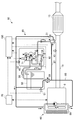
- FIG. 1 is a diagram showing a schematic configuration of the urea SCR system 10.
- the urea SCR system 10 includes a reduction catalyst 13 and a reducing agent injection device 20 as main elements.
- the urea SCR system 10 is a system that reduces and decomposes NO x in exhaust gas using a urea aqueous solution as a reducing agent.
- the urea aqueous solution may be a 32.5% concentration urea aqueous solution having the lowest freezing temperature, for example.
- the freezing temperature in this case is about minus 11 ° C. It is also known that urea aqueous solution crystallizes due to evaporation of moisture.
- the reduction catalyst 13 is disposed in the middle of the exhaust pipe 11 connected to the engine 5 and has a function of selectively reducing NO x contained in the exhaust of the engine 5.
- ammonia urea solution to be injected by the reducing agent injection apparatus 20 is generated by decomposition is adsorbed by the reduction catalyst 13, selectively reduces NO X in the exhaust gas flowing into the reduction catalyst 13 by ammonia Is done.
- the reducing agent injection device 20 injects a urea aqueous solution as a reducing agent into the exhaust pipe 11 upstream of the reduction catalyst 13.
- the injection amount of the urea aqueous solution is controlled so that NO x or ammonia does not flow out downstream of the reduction catalyst 13 based on the concentration of NO x contained in the exhaust gas, the amount of ammonia that can be adsorbed by the reduction catalyst 13, and the like.
- a temperature sensor 15 for detecting the exhaust temperature Tgas is provided in the exhaust pipe 11 upstream of the reduction catalyst 13.
- the exhaust gas temperature Tgas detected by the temperature sensor 15 is also used for estimating the temperature of the reduction catalyst 13.
- the exhaust pipe 11 may be provided with a NO x concentration sensor, an ammonia sensor, or the like (not shown).
- the reducing agent injection device 20 pumps the injection valve 31 fixed to the exhaust pipe 11 upstream of the reduction catalyst 13 and the urea aqueous solution in the storage tank 50 toward the injection valve 31. And a pump module 40 having a pump 41.
- the injection valve 31 and the pump module 40 are connected by a first supply passage 57.
- the first supply passage 57 is provided with a pressure sensor 43 for detecting the pressure of the urea aqueous solution supplied to the injection valve 31.
- the storage tank 50 and the pump module 40 are connected by a second supply passage 58.
- the pump module 40 and the storage tank 50 are also connected by a circulation passage 59.
- the circulation passage 59 branches from the first supply passage 57 and is connected to the storage tank 50.
- An orifice 45 is provided in the middle of the circulation passage 59. The orifice 45 has a function of passing the excess urea aqueous solution to the storage tank 50 side while maintaining the pressure in the first supply passage 57.
- the urea SCR system 10 includes a control device 100 that controls each control element of the reducing agent injection device 20.
- the control device 100 can acquire information of the engine control device 70 via a CAN (Controller Area Network) (not shown).
- the control device 100 can acquire information related to the operating state such as the fuel injection amount, injection timing, and engine speed of the engine 5.
- the control device 100 and the engine control device 70 are separate control devices, but may be configured as a single control device.
- the pump 41 provided in the pump module 40 includes, for example, an electric diaphragm pump or a motor pump.
- the output of the pump 41 is controlled based on a control signal from the control device 100.
- the control device 100 is configured to feedback control the output of the pump 41 so that the pressure of the urea aqueous solution detected by the pressure sensor 43 is maintained at a predetermined target value. Further, when the urea aqueous solution is frozen when the engine 5 is started, the pump 41 starts to be driven after waiting until the urea aqueous solution is thawed.
- the injection valve 31 is an electromagnetic injection valve that can be switched between open and closed by energization control.
- the injection valve 31 includes a coil, and has a structure in which the valve body is moved and opened by a magnetic force generated by energizing the coil. As described above, the pressure of the urea aqueous solution supplied to the injection valve 31 is maintained at a constant pressure, and the control device 100 adjusts the valve opening time according to the target injection amount of the urea aqueous solution.
- the pump module 40 is provided with a flow path switching valve 71.
- the flow path switching valve 71 switches the direction in which the urea aqueous solution pumped by the pump 41 flows.
- the flow path switching valve 71 causes the urea aqueous solution to go from the storage tank 50 side to the injection valve 31 side.
- the suction port of the pump 41 is connected to the second supply passage 58, and the discharge port of the pump 41 is connected to the first supply passage 57.
- the flow path switching valve 71 causes the urea aqueous solution to go from the injection valve 31 side to the storage tank 50 side.
- the suction port of the pump 41 is connected to the first supply passage 57
- the discharge port of the pump 41 is connected to the second supply passage 58.
- the means for collecting the urea aqueous solution in the storage tank 50 is not limited to the above configuration.
- the pump 41 is a pump that can rotate in reverse
- the urea solution may be recovered by rotating the pump 41 in reverse.
- another pump for recovery control and a recovery passage may be provided.
- the reducing agent injection device 20 includes a first cooling water passage 85 and a second cooling water passage 87 that are configured so that the cooling water of the engine 5 can be circulated.
- the first cooling water passage 85 and the second cooling water passage 87 branch from the cooling passage 86 of the engine cooling device 60 provided in the engine 5 and merge with the cooling passage 86 again.
- the first cooling water passage 85 is disposed through the storage tank 50 and the pump module 40.
- the first cooling water passage 85 is also disposed along the first supply passage 57 and the second supply passage 58 of the urea aqueous solution.
- the second cooling water passage 87 is disposed around the injection valve 31.
- An opening / closing valve 81 is provided between the branch point of the second cooling water passage 87 and the storage tank 50 in the first cooling water passage 85.
- the opening / closing valve 81 is switched between opening and closing by the control device 100, and the opening / closing of the first coolant passage 85 is controlled.
- the storage tank 50 and the pump module 40 are provided with temperature sensors 51 and 52 for detecting the temperature Turea of the urea aqueous solution.
- cooling water flows through the second cooling water passage 87. Further, when it is estimated that the aqueous urea solution is frozen based on the sensor values of the temperature sensors 51 and 52 provided in the storage tank 50 and the pump module 40 or the temperature sensor for detecting the outside air temperature, The valve 81 is opened, and the thawing control of the urea aqueous solution is performed.
- the thawing time at this time may be set to an appropriate time based on the sensor values of various temperature sensors. Furthermore, even when the refreezing of the urea aqueous solution is estimated based on the sensor values of various sensors during the operation of the engine 5, the on-off valve 81 may be opened and the heat retention control may be performed.
- cooling water always flows in the second cooling water passage 87. Therefore, during operation of the engine 5, in a state where the injection valve 31 is heated by high-temperature exhaust heat or the like, the cooling water flows into the second cooling water passage 87, and the injection valve 31 can be cooled.
- an electric heater 92 or the like may be used for thawing the pump module 40 and the first and second supply passages 57 and 58 in addition to the cooling water of the engine 5.
- the on / off valve 81 is controlled based on the sensor value of the temperature sensor 51 provided in the storage tank 50, and the on / off control of the electric heater 92 is controlled by the sensor of the temperature sensor 52 provided in the pump module 40. This is done based on the value.
- Energization / non-energization of the electric heater 92 is controlled by the control device 100.
- the electric heater 92 When the temperature Tura of the urea aqueous solution detected by the temperature sensor 52 is equal to or lower than the freezing temperature Tfr of the aqueous urea solution, such as when the engine 5 is started, the electric heater 92 is energized to accelerate the thawing of the frozen aqueous urea solution. In addition, when the temperature of the urea aqueous solution “Turea” is equal to or higher than a predetermined threshold value “Thre_ture”, the electric heater 92 is turned off.
- the apparatus for heating the urea aqueous solution in the pump module 40 is not limited to the electric heater 92.
- heating devices such as an electric heater may be provided at appropriate positions such as the pump module 40, the first supply passage 57, and the second supply passage 58.
- the injection valve 31 is not provided with a cooling device other than the second cooling water passage 87.
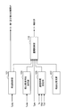
- FIG. 3 is a block diagram functionally showing a part related to the control for promoting the melting of the urea crystals precipitated in the injection valve 31 in the configuration of the control device 100.
- Such a control device 100 is configured around a known microcomputer or the like.
- the control apparatus 100 demonstrated below is an example of an apparatus used for control of the reducing agent injection apparatus 20 provided with the electric heater shown in FIG.
- the control device 100 includes a thawing control unit 101, an estimated thawing time calculation unit 103, an energization time setting unit 105, a crystallization estimation unit 107, and an energization control unit 110. Specifically, each of these units is realized by executing a program by a microcomputer. Further, the control device 100 according to the present embodiment includes information on the outside air temperature Ta, information on the exhaust gas temperature Tgas, information on the cooling water temperature Tcol, information on the temperature Turea of the aqueous urea solution in the storage tank 50, and the power supply of the injection valve 31. Information on the voltage Vbat can be read.
- the thawing control unit 101 opens and closes when it is estimated that the urea aqueous solution is frozen based on the sensor values of the temperature sensors 51 and 52 or the temperature sensor that detects the outside air temperature.
- the valve 81 is opened and the electric heater 92 is energized.
- the thawing control unit 101 opens the on-off valve 81 and energizes the electric heater 92 when the sensor value of the temperature sensor is equal to or lower than the freezing temperature Tfr of the urea aqueous solution.
- the thawing time at this time may be set to an appropriate time based on the sensor values of various temperature sensors.
- the thawing control may be terminated when the temperature of the urea aqueous solution “Turea” is equal to or higher than a predetermined threshold value “Thre_ture”.
- the threshold Thre_turea is set to an appropriate value within a range in which the temperature Turea of the urea aqueous solution does not possibly return to the freezing temperature Tfr or less thereafter. However, if the threshold Thre_turea is too high, the power consumption of the battery increases. Therefore, the threshold Thre_turea can be set to the freezing temperature Tfr + 20 ° C., for example.
- the decompression control by the decompression control unit 101 is not limited to the above example.
- a heating device other than the electric heater 92 may be operated.
- the thawing control unit 101 opens the on-off valve 81 and energizes the electric heater 92 even when the refreezing of the urea aqueous solution is estimated based on the sensor values of various sensors during the operation of the engine 5 to keep the heat. Control may be performed.
- the crystallization estimation unit 107 estimates whether or not the valve body of the injection valve 31 is stuck due to the crystallization of urea in the injection valve 31 when the engine 5 is started.
- the estimation method of urea crystallization is not particularly limited, for example, it can be estimated whether or not urea crystals are precipitated in the injection valve 31 based on the previous situation when the engine 5 was stopped.
- an example of a method for estimating crystallization of urea will be briefly described.
- the crystallization estimation unit 107 continuously records the estimated heat reception amount and heat release amount of the injection valve 31. Further, when the engine 5 is stopped, the crystallization estimation unit 107 stores the heat amount of the injection valve 31 at that time. When the engine 5 is started, the crystallization estimation unit 107 reads the stored heat quantity of the injection valve 31 and compares it with a preset threshold value. Then, the crystallization estimation unit 107 estimates that urea crystals may be precipitated in the injection valve 31 when the amount of heat of the injection valve 31 is equal to or greater than the threshold value.
- the estimated thawing time calculation unit 103 calculates an estimated thawing time Tdef required for thawing the frozen urea aqueous solution.
- the estimated thawing time calculation unit 103 may obtain a preset estimated thawing time Tdef based on the temperature Turea of the aqueous urea solution in the storage tank 50 or the pump module 40.
- the thawing control unit 101 determines whether the electric heater 92 or the like is activated or deactivated according to the temperature Turea of the urea aqueous solution. Therefore, the estimated thawing time Tdef corresponding to the temperature Turea of the urea aqueous solution is determined. It can be obtained in advance by simulation or the like.
- the estimated thawing time Tdef can be obtained with reference to the information.
- the estimated decompression time Tdef may be zero. In this case, it means that the urea aqueous solution is in a thawed state.
- the calculation method of the estimated thawing time Tdef is not limited to this example, and the estimated thawing time Tdef can be calculated by an appropriate method such as considering the outside air temperature together with the temperature Turea of the urea aqueous solution.
- the energization time setting unit 105 sets a time for energizing the coil of the injection valve 31 in order to melt the urea crystals precipitated in the injection valve 31 at an early stage.
- the energization time setting unit 105 may set the energization time T2 based on the outside air temperature Ta.
- the energization of the coil of the injection valve 31 is performed in order to promote the melting of urea crystals in the injection valve 31 by generating heat, but after the engine 5 is started, the heat generation from the coil and the exhaust heat are performed.
- the amount of heat that can be received by the injection valve 31 can be predicted in advance. Therefore, the time until the temperature of the injection valve 31 reaches a predetermined temperature can be estimated according to the outside air temperature Ta that can be regarded as the temperature at which the injection valve 31 starts to be heated.
- the set energization time T2 may be set as the time until the temperature of the injection valve 31 reaches the melting point of the urea crystals, but may be shorter than the time. After thawing of the urea aqueous solution, the urea aqueous solution is supplied to the injection valve 31. It has also been found that the urea crystals are more easily dissolved in the urea aqueous solution as the temperature is higher. Therefore, in this embodiment, in order to promote the melting of the urea crystal, not only the urea crystal is melted at a high temperature, but also the heating of the injection valve 31 so that the urea crystal is easily dissolved in the urea aqueous solution. To include.
- the method of setting the energization time T2 is not limited to this example.
- the energization time T2 may be set based on the cooling water temperature Tcol of the engine 5 in place of or in addition to the outside air temperature Ta.
- the temperature Tcol of the cooling water is also a value related to the temperature at which the injection valve 31 starts to be heated.
- the voltage Vbat of the power supply source supplied to the injection valve 31 may be taken into consideration.
- the energization time T2 may be set short or the energization control may be stopped.
- a coefficient according to the value of the voltage Vbat can be applied, or the energization time T2 can be subtracted according to the value of the voltage Vbat.
- the control device 100 can be configured without the energization time setting unit 105. Even when the energization time T2 is a fixed value regardless of the outside air temperature Ta or the like, it is possible to increase the temperature of the injection valve 31 by energizing only for a short time and promote the melting of urea crystals.
- the energization control unit 110 is configured to energize the injection valve 31 in a state where the exhaust temperature Tgas is equal to or higher than a predetermined first threshold Thre_tgas_1. Therefore, when the energization of the injection valve 31 is started, the exhaust pipe 11 and the like are heated by the exhaust heat, and the portion other than the valve body in the injection valve 31 and the exhaust pipe 11 out of the amount of heat generated from the coil. It is possible to further reduce the amount of heat taken away by the like.
- the first threshold Thre_tgas_1 may be a temperature that is several degrees to several tens of degrees lower than the second threshold Thre_tgas_2 for permitting the operation of the urea SCR system 10, for example.
- the energization control unit 110 estimates the estimated thawing calculated by the estimated thawing time calculation unit 103 when urea crystallization is estimated and the valve body of the injection valve 31 is stuck.
- the coil of the injection valve 31 is energized for the energization time T2. Thereby, the coil generates heat, and the temperature of the injection valve 31 can be raised. As a result, the melting of urea crystals precipitated in the injection valve 31 can be promoted.
- the current value supplied to the injection valve 31 is preferably set to a value that does not lift the valve body of the injection valve 31.
- This energization control is performed before the urea aqueous solution is supplied to the injection valve 31.
- the valve body When the valve body is turned on, the valve body comes into contact with the valve seat surface after that, so that the valve body or the valve seat surface is controlled. This is because wear may occur.
- the energization control unit 110 energizes the injection valve 31 so that the end time of the estimated thawing time Tdef and the end time of the energization time T2 coincide. Specifically, the energization control unit 110 sets a time obtained by subtracting the energization time T2 from the estimated thawing time Tdef as the threshold T1, and the execution time (defrosting execution time) of the thawing control by the thawing control unit 101 reaches the threshold T1. When this is done, energization of the injection valve 31 is started.
- the energization control unit 110 permits the operation of the urea SCR system 10 by setting a flag or the like when the energization time T2 has elapsed since the energization of the injection valve 31 was started. In this case, the thawing control of the urea aqueous solution is also completed, and when the exhaust temperature Tgas exceeds the second threshold Thre_tgas_2, the driving of the pump 41 is started and the reducing agent injection device 20 is filled with the urea aqueous solution. . At this time, the injection valve 31 is heated, and the urea crystals in the injection valve 31 are melted or rapidly melted when the urea aqueous solution reaches. Therefore, the injection control of the urea aqueous solution by the injection valve 31 can be started promptly.
- the energization control unit 110 permits the operation of the urea SCR system 10 immediately when urea crystallization is not estimated and the valve body of the injection valve 31 is not fixed. In this case, after the thawing control of the urea aqueous solution is completed and the exhaust temperature Tgas exceeds the second threshold value Thre_tgas_2, the driving of the pump 41 is started, and the reducing agent injection device 20 is filled with the urea aqueous solution.
- Control Method of Reducing Agent Injection Device ⁇ 4.
- control for promoting the melting of urea crystals when the engine 5 is started will be described. To do.
- the control method routine described below may be executed every time the engine 5 is started.
- FIG. 4 shows a time chart for explaining the melting promotion control of urea crystals
- FIG. 5 shows a flow chart for explaining the melting promotion control of urea crystals
- FIG. 6 is a flowchart for explaining the energization control process in detail. The following description will be given with reference to FIGS. 1 and 3 together.
- step S10 the crystallization estimation unit 107 of the control device 100 reads the status stored when the engine 5 was stopped last time, and the crystallization of urea is performed. It is determined whether or not the injection valve 31 is stuck.
- step S10: No the control device 100 permits the operation of the urea SCR system 10. In this case, the control device 100 waits until the urea aqueous solution thawing control is completed and the exhaust gas temperature Tgas reaches the second threshold Thre_tgas_2, starts driving the pump 41, and injects the urea aqueous solution. Start control.
- step S20 the estimated thawing time calculation unit 103 of the control device 100 calculates the estimated thawing time Tdef. As described above, the estimated thawing time calculation unit 103 obtains the estimated thawing time Tdef based on the temperature Turea of the aqueous urea solution in the storage tank 50, for example.
- step S30 the control device 100 performs energization control.
- step S41 the energization control unit 110 of the control device 100 determines whether or not the exhaust gas temperature Tgas is equal to or higher than the first threshold value Thre_tgas_1.
- step S41: No the energization control unit 110 waits until the exhaust gas temperature Tgas becomes equal to or higher than the first threshold value Thre_thre_1.
- step S42 the energization control unit 110 determines whether or not the thawing control is currently being executed.
- the energization control unit 110 determines whether or not the previous thawing execution time is equal to or greater than the threshold T1.
- the threshold T1 can be a value obtained by subtracting the energization time T2 from the estimated thawing time Tdef calculated in step S20.
- the energization time T2 is set by the energization time setting unit 105 based on the outside air temperature Ta, the cooling water temperature Tcol, the power supply voltage Vbat of the injection valve 31, and the like.
- step S43: No If the thawing execution time so far is less than the threshold T1 (step S43: No), the process returns to step S41, and the control device 100 repeats the processing of each step so far.
- step S44 when the thawing execution time so far is equal to or greater than the threshold value T1 (step S43: Yes), in step S44, the energization control unit 110 starts energizing the coil of the injection valve 31 (t1 in FIG. 4).
- step S42 if the decompression control is not necessary (including the case where the decompression execution time is zero) or if the decompression control has already been completed (step S42: No), the process proceeds to step S44 at this time.
- the energization control unit 110 starts energizing the coil of the injection valve 31.
- the current value supplied to the injection valve 31 is in a range where the valve body of the injection valve 31 does not lift.
- the energization control unit 110 After energization of the coil of the injection valve 31 is started, in step S45, the energization control unit 110 repeatedly determines whether or not the energization time has reached the threshold value T2 (period from t1 to t2 in FIG. 4). When the energization time has reached the threshold value T2 (step S45: Yes), in step S46, the energization control unit 110 stops energizing the coil of the injection valve 31. Thereby, the energization control to the coil of the injection valve 31 is completed (t2 in FIG. 4).
- step S40 in FIG. 5 the energization control unit 110 permits the operation of the urea SCR system 10.
- the control device 100 since the thawing control of the urea aqueous solution has already been completed and the exhaust gas temperature Tgas has reached the second threshold value Thre_tgas_2, the control device 100 immediately starts driving the pump 41, The aqueous solution injection control is started. At this time, the injection valve 31 is heated, and the urea crystals in the injection valve 31 are melted or rapidly melted by the urea aqueous solution.
- the energization of the coil of the injection valve 31 is performed after the exhaust temperature Tgas becomes equal to or higher than the first threshold Thre_tgas_1. Further, the reducing agent injection device 20 obtains the necessary energization time T2, and the energization time T2 ends in accordance with the end time of the estimated defrosting time when the frozen urea aqueous solution is predicted to be thawed. Energize the coil. Therefore, when the exhaust pipe 11 and the injection valve 31 are heated to some extent, the injection valve 31 is efficiently heated by energizing the coil for the minimum necessary energization time T2. Thereby, the power consumption of the battery is reduced, and the deterioration of the coil due to heat generation can be suppressed.
Landscapes
- Engineering & Computer Science (AREA)
- Chemical & Material Sciences (AREA)
- Chemical Kinetics & Catalysis (AREA)
- Environmental & Geological Engineering (AREA)
- Health & Medical Sciences (AREA)
- General Chemical & Material Sciences (AREA)
- Analytical Chemistry (AREA)
- Oil, Petroleum & Natural Gas (AREA)
- Biomedical Technology (AREA)
- Combustion & Propulsion (AREA)
- Toxicology (AREA)
- Mechanical Engineering (AREA)
- General Engineering & Computer Science (AREA)
- Exhaust Gas After Treatment (AREA)
- Exhaust Gas Treatment By Means Of Catalyst (AREA)
Abstract
Description
まず、図1を参照して、本発明の第1の実施の形態にかかる還元剤噴射装置20を備えた尿素SCRシステム10の全体構成例について説明する。図1は、尿素SCRシステム10の概略構成を示す図である。尿素SCRシステム10は、還元触媒13と、還元剤噴射装置20とを主たる要素として備えている。
次に、還元剤噴射装置20の構成について詳細に説明する。図1に示すように、還元剤噴射装置20は、還元触媒13よりも上流側で排気管11に固定された噴射弁31と、貯蔵タンク50内の尿素水溶液を噴射弁31に向けて圧送するポンプ41を有するポンプモジュール40とを備える。
次に、本実施形態にかかる還元剤噴射装置20の制御に用いられる制御装置100の構成例について説明する。図3は、制御装置100の構成のうち、噴射弁31内に析出した尿素の結晶の融解を促進させるための制御に関連する部分を機能的に示すブロック図である。かかる制御装置100は、公知のマイクロコンピュータ等を中心に構成される。なお、以下に説明する制御装置100は、図2に示す電熱ヒータを備えた還元剤噴射装置20の制御に用いる装置の例である。
次に、図4~図6を参照して、本実施形態にかかる制御装置100により実行される還元剤噴射装置の制御方法として、エンジン5の始動時における、尿素の結晶の融解促進制御について説明する。以下に説明する制御方法のルーチンは、エンジン5の始動時において毎回実行されるようにしてもよい。
Claims (12)
- 内燃機関の始動時に還元剤を装置内に充填し、噴射弁により前記還元剤を前記内燃機関の排気通路に噴射させる制御を行う還元剤噴射装置の制御装置において、
前記内燃機関の排気温度が所定の閾値以上になった後に、前記噴射弁のコイルに所定時間通電することにより前記噴射弁を昇温させて、前記噴射弁内に析出した前記還元剤の結晶の融解を促進させる通電制御を行う通電制御部を備えることを特徴とする、還元剤噴射装置の制御装置。 - 前記内燃機関の始動時に、凍結した前記還元剤の解凍に要する推定解凍時間を算出する推定解凍時間演算部を備え、
前記通電制御部は、前記推定解凍時間がゼロでない場合に、前記内燃機関の排気温度が所定の閾値以上になった後、前記推定解凍時間の経過前に前記噴射弁のコイルへの通電を開始することを特徴とする、請求項1に記載の還元剤噴射装置の制御装置。 - 前記通電制御部は、解凍実施時間が、前記推定解凍時間から前記所定時間を引いた値である閾値に到達したときに前記コイルへの通電を開始することを特徴とする、請求項2に記載の還元剤噴射装置の制御装置。
- 前記通電制御部は、前記推定解凍時間がゼロの場合には、前記内燃機関の排気温度が所定の閾値以上になったときに前記コイルへの通電を開始することを特徴とする、請求項2に記載の還元剤噴射装置の制御装置。
- 前記所定時間は、あらかじめ設定された値であることを特徴とする、請求項1~4のいずれか1項に記載の還元剤噴射装置の制御装置。
- 前記所定時間は、少なくとも外気温に基づいて設定される値であることを特徴とする、請求項1~4のいずれか1項に記載の還元剤噴射装置の制御装置。
- 前記所定時間は、さらに前記噴射弁の電源電圧に基づいて設定される値であることを特徴とする、請求項6に記載の還元剤噴射装置の制御装置。
- 前記推定解凍時間演算部は、少なくとも前記還元剤の温度に基づいて前記推定解凍時間を算出することを特徴とする、請求項2~7のいずれか一項に記載の還元剤噴射装置の制御装置。
- 前記通電制御部は、前記所定時間の経過後に、前記還元剤の噴射制御の実行を許可することを特徴とする、請求項1~8のいずれか一項に記載の還元剤噴射装置の制御装置。
- 直前の前記内燃機関の停止時に前記噴射弁内に前記結晶が析出したか否かを推定する結晶化推定部を備え、
前記通電制御部は、前記結晶の析出が予測されたときに前記コイルへの通電制御を行うことを特徴とする、請求項1~9のいずれか一項に記載の還元剤噴射装置の制御装置。 - 内燃機関の始動時に還元剤を装置内に充填し、噴射弁により前記還元剤を前記内燃機関の排気通路に噴射させる制御を行う還元剤噴射装置の制御方法において、
前記内燃機関の排気温度が所定の閾値以上になった後に、前記噴射弁のコイルに所定時間通電することにより前記噴射弁を昇温させて、前記噴射弁内に析出した前記還元剤の結晶の融解を促進させる通電制御を行うステップを備えることを特徴とする、還元剤噴射装置の制御方法。 - 請求項1~10のいずれか一項に記載の制御装置と、
貯蔵タンク内の還元剤を圧送するポンプと、
前記還元剤を内燃機関の排気通路に噴射する噴射弁と、
を備えることを特徴とする、還元剤噴射装置。
Priority Applications (5)
| Application Number | Priority Date | Filing Date | Title |
|---|---|---|---|
| US15/520,289 US10240504B2 (en) | 2014-10-23 | 2015-09-30 | Control device and control method for reducing agent injection device, and reducing agent injection device |
| AU2015334175A AU2015334175B2 (en) | 2014-10-23 | 2015-09-30 | Control device and control method for reducing agent injection device, and reducing agent injection device |
| CN201580057368.4A CN107076001B (zh) | 2014-10-23 | 2015-09-30 | 还原剂喷射装置的控制装置及控制方法、以及还原剂喷射装置 |
| JP2016555152A JP6274698B2 (ja) | 2014-10-23 | 2015-09-30 | 還元剤噴射装置の制御装置及び制御方法並びに還元剤噴射装置 |
| DE112015003782.9T DE112015003782T5 (de) | 2014-10-23 | 2015-09-30 | Steuervorrichtung und Steuerverfahren für ein Reduktionsmitteleinspritzgerät sowie ein Reduktionsmitteleinspritzgerät |
Applications Claiming Priority (2)
| Application Number | Priority Date | Filing Date | Title |
|---|---|---|---|
| JP2014216277 | 2014-10-23 | ||
| JP2014-216277 | 2014-10-23 |
Publications (1)
| Publication Number | Publication Date |
|---|---|
| WO2016063697A1 true WO2016063697A1 (ja) | 2016-04-28 |
Family
ID=55760742
Family Applications (1)
| Application Number | Title | Priority Date | Filing Date |
|---|---|---|---|
| PCT/JP2015/077781 Ceased WO2016063697A1 (ja) | 2014-10-23 | 2015-09-30 | 還元剤噴射装置の制御装置及び制御方法並びに還元剤噴射装置 |
Country Status (6)
| Country | Link |
|---|---|
| US (1) | US10240504B2 (ja) |
| JP (1) | JP6274698B2 (ja) |
| CN (1) | CN107076001B (ja) |
| AU (1) | AU2015334175B2 (ja) |
| DE (1) | DE112015003782T5 (ja) |
| WO (1) | WO2016063697A1 (ja) |
Cited By (5)
| Publication number | Priority date | Publication date | Assignee | Title |
|---|---|---|---|---|
| GB2545674A (en) * | 2015-12-21 | 2017-06-28 | Bamford Excavators Ltd | Dosing module |
| WO2018079524A1 (ja) * | 2016-10-25 | 2018-05-03 | いすゞ自動車株式会社 | 尿素水供給システム及びその制御方法 |
| JP2019052573A (ja) * | 2017-09-14 | 2019-04-04 | 日野自動車株式会社 | 尿素噴射システムの制御方法 |
| CN110062844A (zh) * | 2017-03-09 | 2019-07-26 | 宝马股份公司 | 用于将流体混合到内燃机的燃烧用空气中的设备 |
| DE112020005815T5 (de) | 2019-11-25 | 2022-09-15 | Isuzu Motors Limited | Reduktionsmittelauftauvorrichtung für ein fahrzeug |
Families Citing this family (7)
| Publication number | Priority date | Publication date | Assignee | Title |
|---|---|---|---|---|
| JP2016094863A (ja) * | 2014-11-13 | 2016-05-26 | いすゞ自動車株式会社 | 尿素水噴射システム及び尿素水噴射装置の結晶化防止方法 |
| JP7109143B2 (ja) * | 2018-06-28 | 2022-07-29 | ロベルト・ボッシュ・ゲゼルシャフト・ミト・ベシュレンクテル・ハフツング | 加熱システム |
| DE112020001222B4 (de) * | 2019-03-14 | 2024-05-02 | Cummins Inc. | Dieselabgasfluiddosiererschutz bei kalten Umgebungstemperaturbedingungen durch Verfahren zur Zylinderabschaltung |
| FR3108263B1 (fr) * | 2020-03-18 | 2022-02-11 | Vitesco Technologies | Procédé d’entretien d’un dispositif de filtration d’un systeme d’extraction d’un liquide d’un reservoir d’un vehicule automobile |
| CN116641781B (zh) * | 2023-06-15 | 2025-12-23 | 潍柴动力股份有限公司 | 解决尿素喷嘴结晶堵塞的控制方法、装置和电子设备 |
| GB2633824B (en) * | 2023-09-22 | 2025-12-10 | Perkins Engines Co Ltd | Apparatus and methods related to coolant diverter valves |
| CN117703569B (zh) * | 2024-01-04 | 2026-01-20 | 潍柴动力股份有限公司 | 一种预防尿素喷嘴结晶的方法、装置及发动机系统 |
Citations (8)
| Publication number | Priority date | Publication date | Assignee | Title |
|---|---|---|---|---|
| JP2005127318A (ja) * | 2003-09-19 | 2005-05-19 | Nissan Diesel Motor Co Ltd | エンジンの排気浄化装置 |
| US20090077949A1 (en) * | 2007-04-03 | 2009-03-26 | Robert Bosch Gmbh | Procedure for operating a reducing agent metering valve of a scr-exhaust gas purifying system |
| JP2011074889A (ja) * | 2009-10-01 | 2011-04-14 | Hitachi Constr Mach Co Ltd | 排気浄化装置 |
| JP2012091728A (ja) * | 2010-10-28 | 2012-05-17 | Daimler Ag | プラグインハイブリッド電気自動車及び該プラグインハイブリッド電気自動車の制御方法 |
| WO2012090801A1 (ja) * | 2010-12-27 | 2012-07-05 | ボッシュ株式会社 | 排気浄化システム及び排気浄化システムの制御方法 |
| JP2013221425A (ja) * | 2012-04-13 | 2013-10-28 | Denso Corp | 排気浄化装置のインジェクタ制御装置 |
| JP2014012992A (ja) * | 2012-07-03 | 2014-01-23 | Toyota Motor Corp | 内燃機関の排気浄化装置 |
| JP2014177883A (ja) * | 2013-03-14 | 2014-09-25 | Bosch Corp | 還元剤供給装置の制御方法 |
Family Cites Families (5)
| Publication number | Priority date | Publication date | Assignee | Title |
|---|---|---|---|---|
| US7467749B2 (en) * | 2004-04-26 | 2008-12-23 | Tenneco Automotive Operating Company Inc. | Methods and apparatus for injecting atomized reagent |
| ATE512300T1 (de) * | 2006-07-12 | 2011-06-15 | Delphi Tech Holding Sarl | Dosierpumpe für eines reduktionsmittels |
| JP5503277B2 (ja) * | 2009-12-15 | 2014-05-28 | ボッシュ株式会社 | 還元剤噴射弁の制御装置 |
| GB201217144D0 (en) * | 2012-09-26 | 2012-11-07 | Delphi Tech Holding Sarl | A fluid injector |
| GB2517141A (en) * | 2013-07-30 | 2015-02-18 | Gm Global Tech Operations Inc | A control apparatus for a diesel exhaust fluid in-jector |
-
2015
- 2015-09-30 CN CN201580057368.4A patent/CN107076001B/zh not_active Expired - Fee Related
- 2015-09-30 US US15/520,289 patent/US10240504B2/en not_active Expired - Fee Related
- 2015-09-30 AU AU2015334175A patent/AU2015334175B2/en not_active Ceased
- 2015-09-30 WO PCT/JP2015/077781 patent/WO2016063697A1/ja not_active Ceased
- 2015-09-30 DE DE112015003782.9T patent/DE112015003782T5/de not_active Withdrawn
- 2015-09-30 JP JP2016555152A patent/JP6274698B2/ja active Active
Patent Citations (8)
| Publication number | Priority date | Publication date | Assignee | Title |
|---|---|---|---|---|
| JP2005127318A (ja) * | 2003-09-19 | 2005-05-19 | Nissan Diesel Motor Co Ltd | エンジンの排気浄化装置 |
| US20090077949A1 (en) * | 2007-04-03 | 2009-03-26 | Robert Bosch Gmbh | Procedure for operating a reducing agent metering valve of a scr-exhaust gas purifying system |
| JP2011074889A (ja) * | 2009-10-01 | 2011-04-14 | Hitachi Constr Mach Co Ltd | 排気浄化装置 |
| JP2012091728A (ja) * | 2010-10-28 | 2012-05-17 | Daimler Ag | プラグインハイブリッド電気自動車及び該プラグインハイブリッド電気自動車の制御方法 |
| WO2012090801A1 (ja) * | 2010-12-27 | 2012-07-05 | ボッシュ株式会社 | 排気浄化システム及び排気浄化システムの制御方法 |
| JP2013221425A (ja) * | 2012-04-13 | 2013-10-28 | Denso Corp | 排気浄化装置のインジェクタ制御装置 |
| JP2014012992A (ja) * | 2012-07-03 | 2014-01-23 | Toyota Motor Corp | 内燃機関の排気浄化装置 |
| JP2014177883A (ja) * | 2013-03-14 | 2014-09-25 | Bosch Corp | 還元剤供給装置の制御方法 |
Cited By (12)
| Publication number | Priority date | Publication date | Assignee | Title |
|---|---|---|---|---|
| GB2545674A (en) * | 2015-12-21 | 2017-06-28 | Bamford Excavators Ltd | Dosing module |
| US10480374B2 (en) | 2015-12-21 | 2019-11-19 | J.C. Bamford Excavators Limited | Dosing module |
| GB2545674B (en) * | 2015-12-21 | 2021-03-31 | Bamford Excavators Ltd | Dosing module |
| WO2018079524A1 (ja) * | 2016-10-25 | 2018-05-03 | いすゞ自動車株式会社 | 尿素水供給システム及びその制御方法 |
| JP2018071362A (ja) * | 2016-10-25 | 2018-05-10 | いすゞ自動車株式会社 | 尿素水供給システム及びその制御方法 |
| CN109863284A (zh) * | 2016-10-25 | 2019-06-07 | 五十铃自动车株式会社 | 尿素水供给系统及其控制方法 |
| US10934914B2 (en) | 2016-10-25 | 2021-03-02 | Isuzu Motors Limited | Urea water supply system and control method therefor |
| CN109863284B (zh) * | 2016-10-25 | 2021-05-11 | 五十铃自动车株式会社 | 尿素水供给系统及其控制方法 |
| CN110062844A (zh) * | 2017-03-09 | 2019-07-26 | 宝马股份公司 | 用于将流体混合到内燃机的燃烧用空气中的设备 |
| CN110062844B (zh) * | 2017-03-09 | 2021-08-31 | 宝马股份公司 | 用于将流体混合到内燃机的燃烧用空气中的设备 |
| JP2019052573A (ja) * | 2017-09-14 | 2019-04-04 | 日野自動車株式会社 | 尿素噴射システムの制御方法 |
| DE112020005815T5 (de) | 2019-11-25 | 2022-09-15 | Isuzu Motors Limited | Reduktionsmittelauftauvorrichtung für ein fahrzeug |
Also Published As
| Publication number | Publication date |
|---|---|
| CN107076001B (zh) | 2019-08-23 |
| JP6274698B2 (ja) | 2018-02-07 |
| US20170321582A1 (en) | 2017-11-09 |
| AU2015334175B2 (en) | 2018-12-06 |
| DE112015003782T5 (de) | 2017-05-11 |
| US10240504B2 (en) | 2019-03-26 |
| JPWO2016063697A1 (ja) | 2017-07-27 |
| AU2015334175A1 (en) | 2017-05-04 |
| CN107076001A (zh) | 2017-08-18 |
Similar Documents
| Publication | Publication Date | Title |
|---|---|---|
| JP6274698B2 (ja) | 還元剤噴射装置の制御装置及び制御方法並びに還元剤噴射装置 | |
| JP6088865B2 (ja) | 還元剤供給装置の制御方法 | |
| CN107109982B (zh) | 尿素水喷射系统以及尿素水喷射装置的防止结晶化方法 | |
| JP6663680B2 (ja) | 還元剤噴射装置の制御装置 | |
| JP5979770B2 (ja) | 還元剤供給装置の制御装置及び制御方法 | |
| EP3533978B1 (en) | Urea water supply system and control method therefor | |
| JPWO2014061377A1 (ja) | 還元剤回収制御方法及び還元剤供給装置並びに電子制御装置 | |
| JP5533363B2 (ja) | Scrシステム | |
| CN110657006B (zh) | 加热系统 | |
| JP7200735B2 (ja) | 排気浄化制御装置 | |
| JP2012127308A (ja) | 還元剤供給装置及び内燃機関の排気浄化装置 | |
| WO2015001858A1 (ja) | 還元剤供給装置及びその制御方法 | |
| JP6753949B2 (ja) | ヒータ制御装置及びヒータ制御方法 | |
| JP6576813B2 (ja) | 還元剤供給装置 | |
| JPWO2014103869A1 (ja) | 還元剤供給装置の制御方法及び還元剤供給装置 | |
| JP6493953B2 (ja) | 還元剤噴射装置の制御装置及び制御方法並びに還元剤噴射装置 | |
| JP2015017576A (ja) | 還元剤供給装置 | |
| JP2014015856A (ja) | 還元剤供給装置及び液体還元剤の回収制御方法並びに排気浄化装置 | |
| JP2019027392A (ja) | 還元剤解凍装置 |
Legal Events
| Date | Code | Title | Description |
|---|---|---|---|
| 121 | Ep: the epo has been informed by wipo that ep was designated in this application |
Ref document number: 15852163 Country of ref document: EP Kind code of ref document: A1 |
|
| ENP | Entry into the national phase |
Ref document number: 2016555152 Country of ref document: JP Kind code of ref document: A |
|
| WWE | Wipo information: entry into national phase |
Ref document number: 112015003782 Country of ref document: DE |
|
| WWE | Wipo information: entry into national phase |
Ref document number: 15520289 Country of ref document: US |
|
| ENP | Entry into the national phase |
Ref document number: 2015334175 Country of ref document: AU Date of ref document: 20150930 Kind code of ref document: A |
|
| 122 | Ep: pct application non-entry in european phase |
Ref document number: 15852163 Country of ref document: EP Kind code of ref document: A1 |